materials quality assurance procedures manual 2012 · pdf filematerials quality assurance...
TRANSCRIPT
Materials Quality Assurance Procedures Manual 2012
4.01
4.01 CONCRETE PIPE INSPECTION 4.01.01. Scope
A. This procedure is to supplement the normal sampling, testing and inspection of concrete pipe by listing various exceptions to the applicable documents. These exceptions are found in Sections 4.01.03, 4.01.04 and 4.01.05 of this document.
4.01.02. Reference Documents
A. Standard Specifications for Construction.
B. AASHTO and ASTM Standards:
ASTM C 14 AASHTO M 86 Concrete Sewer, Storm Drain, and Culvert Pipe (Unreinforced)
ASTM C 76 AASHTO M 170 Reinforced Concrete Culvert, Storm Drain and Sewer Pipe
ASTM C 412 AASHTO M 178 Concrete Drain Tile ASTM C 507 AASHTO M 207 Reinforced Concrete Elliptical Culvert, Storm Drain and
Sewer Pipe ASTM C 655 AASHTO M 242 Reinforced Concrete D-Load Culvert, Storm Drain and
Sewer Pipe ASTM C 39 AASHTO T 22 Compressive Strength of Cylindrical Concrete
Specimens ASTM C 31 AASHTO T 23 Making and Curing Concrete Test Specimens in the
Field ASTM E 4 AASHTO T 67 Standard Practices for Load Verification of Testing
Machines ASTM C 497 AASHTO T 280 Standard Methods of Testing Concrete Pipe, Sections,
or Tile C. MDOT Materials Source Guide
4.01.03. Basis of Acceptance
A. Pipe less than 3 feet in diameter will be tested by the three edge bearing method, using full sized units of pipe, unless otherwise specifically authorized by MDOT.
B. Pipe 3 feet in diameter and larger may be tested for concrete strength by testing cores
obtained from the pipe or by the three edge bearing method, at the option of the manufacturer.
C. In special cases, and with prior MDOT approval, concrete strength may be determined by
making and testing at least two 6 x 12 inch cylinders from the concrete used in casting the pipe.
1. Cylinders are to be made in accordance with ASTM C 31 and tested in accordance
with ASTM C 39.
Page 75 of 317

Materials Quality Assurance Procedures Manual 2012
4.01
4.01.04. Calibration of Testing Devices
A. The calibration table for each device used (showing the gauge reading and the load, in newtons) must be prominently posted near the testing equipment.
B. Post the "Certification of Calibration" near the testing equipment.
4.01.05. Reports
A. The results of inspection will be reported on "Field Report for Concrete Pipe", Form 1920.
Page 76 of 317

Materials Quality Assurance Procedures Manual 2012
4.02
4.02 CORRUGATED METAL PIPE AND METAL END SECTIONS FABRICATION 4.02.01. Scope
A. This procedure is to be followed for acceptance inspection where certification has not been made, visual inspection of small quantities, or where certification verification inspection is required.
4.02.02. Reference Documents
A. AASHTO Standards
M 36 Corrugated Steel Pipe, Metallic Coated, for Sewers and Drains M 196 Corrugated Aluminum Pipe for Sewers and Drains M 245 Corrugated Steel Pipe, Polymer Precoated, for Sewers and Drains
B. Materials Quality Assurance Procedures Manual
3.03 Certification Verification Sampling and Testing 4.09 Thickness of Zinc and Epoxy Coatings Applied to a Ferrous Base
C. Standard Specifications for Construction 4.02.03. Procedure
A. Corrugated Metal Pipe
1. This inspection is primarily a visual inspection of an order of fabricated pipe and consists essentially of dimensional measurements and inspection of workmanship. It includes, but is not limited to, the inspection and/or reporting of the following:
- Shape (circular, pipe arch, etc.). - Annular or helical corrugations. - Dimensions, spacing, and placement of rivets. - Lock seam or welded seam. - Widths of laps, and depth and spacing of corrugations. - Weight of metallic coating (on steel pipe), heat number and thickness of sheet. - Thickness of polymer coating, each side, on polymer coated pipe. - End finish. - Size, location, condition, and number of perforations (when required). - Quantity of each size of pipe in the order. - Workmanship.
2. The fabricator or contractor must provide assistance needed for proper inspection,
depending on where the inspection is being conducted.
3. Uncertified sheets used in the fabricated order must be sampled and tested when their quantity exceeds the visual inspection limits found in the Materials Acceptance Requirements Table of this manual.
Page 77 of 317

Materials Quality Assurance Procedures Manual 2012
4.02
4. Determination of the metallic coating thickness by the use of a magnetic thickness gage, or positector, will be permitted on "Visual Inspection" quantities only.
5. Poor workmanship is sufficient cause for rejection of uncertified materials. Poor
workmanship includes but is not limited to the presence of one or more of the following in any individual pipe:
- Uneven laps in riveted or spot welded pipe. - Elliptical shape in pipe intended to be round. - Variation from a straight centerline. - Ragged or diagonal sheared edges. - Loose, unevenly lined, or unevenly spaced rivets. - Poorly formed rivet heads. - Loose or poorly formed lockseams. - Cracks in welded seams. - Unfinished ends (if order requires finished ends). - Illegible markings on the metal sheet. - Lack of rigidity. - Bruised, scaled, broken, or otherwise damaged metallic coating. - Damaged or unbonded polymer coating. - Dents or bends in the metal.
NOTE: Certified material should normally be rejected only for significant deficiencies.
6. The metallic coating (zinc or aluminum) on steel coupling bands must be the same as
the coating as the pipe to be coupled. Aluminum coupling bands are to be used with aluminum pipe.
B. Metal End Sections
1. This inspection is primarily a visual inspection of an order of fabricated metal end
sections, and consists essentially of dimensional measurements, determination of coating thickness, and workmanship.
2. The metallic coating on steel end sections must be the same as the coating on the
pipe except zinc-coated steel end sections may be used with aluminum-coated steel pipe.
3. Aluminum end sections must be used with aluminum pipe.
4. Determination of the metallic coating thickness may be made by the use of a magnetic
thickness gage or positector.
5. The end sections must be furnished with the appropriate coupling band and connector section.
4.02.04. Identification of Material
A. Tag a sufficient number of pieces of pipe, coupling bands and end sections so the order can be identified at the project site.
B. Each tag must show the date of fabrication, Control Section ID, and Job Number.
Page 78 of 317

Materials Quality Assurance Procedures Manual 2012
4.02
4.02.05. Certification Verification
A. A sufficient number of pieces in the shipment will be checked and reported to validate the quality of the manufacturer's product.
B. Information may be reported for each piece of material checked, or if appropriate, averages of
several measurements, weights, etc. may be reported.
C. The remarks section of all certification verification inspection reports must include a statement as to whether the material does or does not meet specification requirements.
4.02.06. Reports
A. Inspection of corrugated metal pipe and end sections will be reported on the Inspectors Daily Report.
Page 79 of 317

Materials Quality Assurance Procedures Manual 2012
4.03
4.03 LANE TIE AND CONCRETE ANCHOR TESTING 4.03.01. Scope
A. The purpose of performing lane tie or concrete anchor pull-out tests is to determine if these devices have been properly installed. When properly installed, lane ties or anchors should develop pull-out loads that exceed requirements of MDOT Specifications. Lane ties refer to deformed reinforcing bars (with or without epoxy coating), that are cast into the concrete. Concrete anchors refer to mechanical or adhesive anchors that are drilled and set into hardened concrete. Adhesive concrete anchors may also be used as lane ties.
4.03.02. Reference Documents
A. Lane tie load sustaining requirements are covered by the current edition of MDOT's Standard Specifications for Construction 602.03F and 914.10, Standard Plan R-41 series, and the contract documents.
4.03.03. Equipment and Supplies
A. Testing Equipment
- Testing frame; including hydraulic cylinder. - Hydraulic pump unit; including hose and hydraulic pressure gage. - 50 pound weight with attached ¾ inch diameter rod. - Dial indicator kit. - Drawbar and wedge fixture.
B. Additional Equipment
- Wood blocking for frame legs - Crescent wrench - Screw driver - Vice-grips - Hammer - Measuring tape - Shovel
4.03.04. Selection of Sample
A. Do not perform lane tie pull-out tests until the concrete has attained a flexural strength of 550 psi [653 psi for certain torque anchors].
B. Select a minimum of 15 samples for testing. Samples should be selected from various
portions of the project, and scattered throughout the available area. Any areas where there have been changes in method of installation, changes in personnel, changes in equipment, or equipment malfunction should be tested. The number of times that a job must be checked will be determined by the Construction/Project Engineer based on the amount of bulkhead joints with anchoring devices.
Page 80 of 317

Materials Quality Assurance Procedures Manual 2012
4.03
4.03.05. Test Procedure for Anchoring Devices Used as Lane Ties
A. Attach drawbar or wedge fixture to the anchoring device which is to be tested.
CAUTION: Any misalignment must be compensated for by wood blocking placed between the appropriate frame leg and the concrete.
B. Slightly preload the anchoring device 100 lbf to 200 lbf, by applying pressure with the
hydraulic cylinder.
C. Position and preload the dial indicator to measure extrusion of the anchoring device. Zero the dial indicator before applying any additional load.
CAUTION: When applying load to anchors, do not stand behind the frame. Sudden releases can occur, causing the frame to fly back.
D. Apply load to the anchoring device using slow uniform strokes on the hydraulic pump handle.
E. Monitor both the pressure gage and the dial indicator until one of the following occurs:
1. The anchoring device extrudes 1/16 inch out of the concrete. When this happens,
record the load at this point.
NOTE: Misalignment can sometimes cause the dial indicator to move opposite of the direction it should. When this happens, watch the anchoring device and re-zero the indicator when actual extrusion is first observed.
2. If there is not sufficient movement of the anchor to reach 1/16 inch extrusion, load to
12,000 lbf and stop. Record the capacity as 12,000 lbf. F. When recording data of anchor pull-out tests, set up data sheet as follows:
Sample Load at Initial Load at 1/16 inch Ultimate Ultimate Number Slippage Extrusion Load Extrusion
G. If the 12,000 lbf load is not reached, the ultimate load is considered to have occurred when
the lane tie loading (as indicated by the pressure gage) remains stationary or decreases as pumping is continued, and anchor extrusion is taking place. Ensure that the gripping devices are not slipping.
H. The lane ties are acceptable if the average load per foot of joint equals or exceeds the
requirements of Section 602.03F of the Standard Specifications. 4.03.06. Test Procedure for Anchoring Devices used for Applications Other Than Lane Ties
A. Use the same procedure as used for lane ties. The requirements for load sustaining capabilities and extrusion will be stated in the Contract Documents.
Page 81 of 317

Materials Quality Assurance Procedures Manual 2012
4.04
4.04 PRESTRESSED STRUCTURAL PRECAST CONCRETE FABRICATION 4.04.01. Scope
A. This prestressed structural precast concrete fabrication inspection procedure should be used to aid the quality assurance inspector (QAI) in interpreting and enforcing the contract documents for prestressed concrete elements. Fabrication inspection includes the time from verifying materials used for fabrication through loading for shipping to the construction site.
4.04.02. Reference Documents
A. QAI must have a thorough knowledge of the following references:
1. The following sections of the MDOT Standard Specifications for Construction (MDOT SSC) as modified by supplemental specification 12SS-001A – Errata, as applicable:
Section 104 Control of the Work Section 105 Control of the Materials Section 708 Prestressed Concrete
2. The following special provisions, as applicable:
12SP-105A Source of Steel and Iron (Buy America) 12SP-604C QC and Acceptance of PCC for Structural Precast Concrete
12SP-708A Special Provision for Strand Debonding 12SP-708B Prestressed Concrete Bulb-Tee Beam
3. Contract plans and specifications
4. Construction Field Services Division (CFS) Materials Source Guide (MSG)
5. MDOT Structural Fabrication Quality Assurance Guidance Document
6. MDOT Structural Fabrication Unit E-Construction Process
7. Prefabrication meeting minutes (if available)
B. QAI must be familiar with the following references:
1. MDOT Structural Fabrication Request for Information Process
2. MDOT Shop Drawing Review Process
3. MDOT Structural Fabrication Nonconformance Process 4. Michigan Test Methods
MTM 102 Michigan Test Method for Abrasion Resistance of Aggregate by the Los
Angeles Machine MTM 108 Michigan Test Method for Materials Finer than No. 75 Sieve in Mineral
Aggregates by Washing MTM 109 Michigan Test Method for Sieve Analysis of Fine, Dense Graded, Open
Page 82 of 317

Materials Quality Assurance Procedures Manual 2012
4.04
Graded, and Coarse Aggregates in the Field MTM 114 Michigan Test Method for Making Concrete Specimens for Freeze-Thaw
Testing of Concrete Coarse Aggregate MTM 115 Michigan Test Method for Testing Concrete for Durability by Rapid
Freezing in Air and Thawing in Water MTM 206 Michigan Test Method for Use of Unbonded Caps in Determination of
Compressive Strength of Hardened Concrete Cylinders
5. AASHTO Standards
T 22 Compressive Strength of Cylindrical Concrete Specimens T 23 Making and Curing Concrete Test Specimens in the Field T 231 Capping Cylindrical Concrete Specimens
6. ASTM Standards
A 185 Standard Specification for Steel Welded Wire Fabric, Plain, for Concrete
Reinforcement A 416 Standard Specification for Low-Relaxation, Seven-Wire Steel Strand for
Prestressed Concrete A 497 Standard Specification for Steel Welded Wire Fabric, Deformed, for
Concrete Reinforcement C 31 Standard Practice for Making and Curing Concrete Test Specimens in
the Field C 39 Standard Test Method for Compressive Strength of Cylindrical Concrete
Specimens C 94 Standard Specification for Ready-Mixed Concrete
C 136 Standard Test Method for Sieve Analysis of Fine and Coarse Aggregates
C 138 Test Method for Density (Unit Weight), Yield and Air Content (Gravimetric) of Concrete
C 143 Standard Test Method for Slump of Hydraulic Cement Concrete C 172 Standard Practice for Sampling Freshly Mixed Concrete C 173 Standard Test Method for Air Content of Freshly Mixed Concrete by the
Volumetric Method C 231 Standard Test Method for Air Content of Freshly Mixed Concrete by the
Pressure Method C 595 Standard Specification for Blended Hydraulic Cements
C 617 Standard Practice for Capping Cylindrical Concrete Specimens C 1231 Standard Practice for Use of Unbonded Caps in determination of
Compressive Strength of Hardened Concrete Cylinders C 1260 Standard Test Method for Potential Alkali Reactivity of Aggregates
(Mortar Bar Method) C 1567 Standard Test Method for Determining the Potential Alkali-Silica
Reactivity of Combinations of Cementitious Materials and Aggregate (Accelerated Mortar Bar Method)
7. PCI Safety and Loss Prevention Manual SLP-100 8. MDOT Accident Prevention Plan
4.04.03. Qualifications, Responsibilities, Duties, and Equipment
Page 83 of 317

Materials Quality Assurance Procedures Manual 2012
4.04
A. Qualifications of the QAI – QAI performing the fabrication inspection must possess the following qualifications: 1. Michigan Professional Engineer (PE) license or Precast/Prestressed Concrete Institute
(PCI) Technician Level II; 2. Michigan Concrete Association (MCA) Level I Field Testing Technician certification or
American Concrete Institute (ACI) Concrete Field Testing Technician – Grade I (except period of effectiveness will be reduced from 5 years to 3 years to match MCA); and
3. Michigan Certified Aggregate Technician (MCAT) Level I (only required for aggregate sampling).
B. Responsibilities of the QAI – QAI performing the fabrication inspection is not permitted to
make changes to the contract and has the following responsibilities:
The Contractor, Fabricator, and MDOT will approach quality control and quality assurance as a team effort to facilitate accurate and timely construction. QAI’s verification does not relieve the Fabricator from the responsibility to perform the required testing and inspection to produce a product satisfying the contract. Though QA inspection may include all aspects of fabrication, the QAI must not supersede QC, which is the responsibility of the Fabricator. If QC is not accomplishing its role then the Structural Fabrication Unit, Engineer, Contractor, and Fabricator must determine the necessary corrections.
QAI is the responsible party, representing the Engineer, who performs quality assurance verification inspection on the element after quality control (QC) inspects and approves the item of work. The QAI must be at the fabrication facility at all times during fabrication as required by the inspection procedure stated below. If issues arise, it will be at the Engineer’s discretion whether to increase the level of QA inspection.
It is the Engineer’s responsibility to engage the Engineer of Record (EOR) when making structural decisions. The Engineer is also responsible for following internal MDOT procedures for review and approval of shop drawings, fabrication procedures, request for information (RFI), nonconformance reports (NCR), and for professional decision making on fabrication problems that arise. The Engineer relies on the Structural Fabrication Unit to manage and assist when appropriate. The Engineer has the prerogative for holding a prefabrication meeting with the Fabricator to discuss and clarify the contract plans and specifications. The Engineer is the responsible party who ensures MDOT’s fabrication QA program is followed for inspection and acceptance of the element. Fabrication should proceed only with approved shop drawings. However, if the Fabricator must proceed prior to receipt of approved shop drawings (performing work at their own risk), ensure that the Structural Fabrication Unit is aware of this activity and await instruction on how to proceed. If the Engineer permits the work to proceed without approved shop drawings, proceed with basic QA functions using the non-approved shop drawings. Later, verify notes against approved drawings. Notify the Structural Fabrication Unit immediately if fabrication is not in conformance with the approved shop drawings.
C. Duties of the QAI – QAI performing the fabrication inspection has the following duties:
1. QAI must thoroughly understand the contract documents. 2. QAI must verify steel material certifications show compliance with Buy America contract
requirements. 3. QAI must be proficient in performing fresh concrete tests, sampling aggregate and other
materials, verifying material traceability, and inspecting concrete pours.
Page 84 of 317

Materials Quality Assurance Procedures Manual 2012
4.04
4. QAI must be proficient in writing reports and using computers. 5. QAI must notify the Engineer if production begins before approved shop drawings are
on the shop floor and provided to the QAI. 6. QAI must communicate all concerns through QCI or whomever the Fabricator directs
during the prefabrication meeting. 7. QAI must communicate with QCI to obtain the work schedule. 8. QAI must follow MDOT’s Structural Fabrication E-Construction Process for closing out
fabrication inspection file.
D. Deficiencies on Local Agency Projects – MDOT’s QAI must notify the Structural Fabrication Unit if they observe fabrication or inspection deficiencies on local agency program (LAP) projects. The Structural Fabrication Engineer will report the deficiencies via email to the Engineer that is responsible for construction oversight of the local agency project and carbon copy the applicable CFS and Design Division LAP Engineers.
E. Inspection Facilities and Access – Facilities for the QAI must be provided by the Fabricator
per contract documents. QAI must have access to all parts of the work at all times. The authority and general duties of the QAI are specified in Section 104.01.D and E of the MDOT SSC.
F. Inspection Equipment – QAI will be furnished with the following items by the Engineer:
1. Contract documents (MDOT SSC, special provisions, standard plans, special details,
plan sheets, etc.) 2. Approved shop drawings (provided by Fabricator) 3. Access to MDOT’s Fabrication Inspection & Construction System (FICS) 4. MDOT shop approval stamp
QAI must provide the following inspection equipment:
1. Computer with high speed internet access 2. Cell phone with camera 3. Flashlight 4. Temperature measuring devices capable of covering the range from 0°F to 200°F 5. Fresh concrete testing equipment (thermometer, slump cone kit, and air-meter) 6. Measuring devices (200 foot and 20 foot steel tape and calipers) 7. Straightedge and levels 8. Safety equipment 9. Other as needed for the project
4.04.04. Inspection Procedure
A. Prefabrication Meeting – Prefabrication meetings facilitate effective quality control and quality assurance on the project and are conducted by MDOT’s Structural Fabrication Unit prior to the start of fabrication and preferably after shop drawings have been approved. The Structural Fabrication Unit, QAI, Fabricator, and QCI must be present, whereas the Engineer and Contractor should be present to ensure a team effort to facilitate accurate and timely construction. Quality assurance and quality control contact information will be shared during this meeting to ensure effective communication.
B. Fabrication Inspection – Prestressed concrete must be fabricated in accordance with the
MDOT SSC and contract documents. QAI and QCI must pass annual MDOT independent assurance testing (IAT) prior to performing fresh concrete testing. Fabrication inspection must be performed as shown below:
Page 85 of 317

Materials Quality Assurance Procedures Manual 2012
4.04
1. Prestressed concrete fabrication inspection consists of verifying compliance with the
approved shop drawings, contract documents, and approved NCRs. RFIs must be incorporated into the approved shop drawings for the QAI to inspect to.
2. An approved Materials Source List (MSL) is provided to the QAI by the Engineer so
that the QAI knows what materials are being incorporated into the project and what the basis of acceptance is. The MSL is used to track material sampling by the QAI and to foster communication with QCI to ensure all required sampling and testing occurs in a timely manner to prevent impacts to the project schedule. It is the Fabricator’s responsibility to notify the QAI when materials are available for sampling.
3. QAI begins by inspecting materials that will be used in the fabrication process and
ensures they are being stored correctly, tagged for traceability purposes, and are in conformance with the contract documents. Next, the QAI inspects the Fabricator’s operations to ensure the condition of the equipment and work area for conformance to the contract documents.
4. MDOT’s Accident Prevention Plan states, “MDOT employees shall not engage in
any act which would endanger another employee or themselves”. QAI must notify the Engineer immediately if work conditions exist that are not safe. If the level of inspection diminishes below what is specified in this QA procedure, due to safety concerns, then the element will not be approved for use.
D. Strand Tensioning
1. General Information – While the strand is still visible, the QAI must inspect the
strands to assure that they are free of oil or other foreign material. Strands not free of oil or foreign material, or that contain kinks, bends, nicks, or other defects (including scale or excessive rust) will be brought to QCs attention that incorporation of these nonconforming strands will render the element unacceptable and the element will not be approved for use.
a. Strands are positioned to duplicate the strand pattern shown on the
approved shop drawings. Changing the vertical position of the strands must have the approval of the Engineer. Changing the horizontal position of the strands to simplify fabrication or to accommodate two strand patterns on a bed is permitted provided the following is still achieved:
i. Specified concrete cover; ii. Center to center distance of strands is at least 2 inches; iii. Number of strands per row is maintained; and iv. Resulting strand pattern is symmetrical about the vertical centerline of
the element.
b. Two strand patterns is permitted to be combined on a casting bed provided the following conditions are met and approved by the Engineer:
i. Bond breaker must be placed on each of the unrequired strands for the full length of each element. Bond breaker (rigid, oversized, and monolithic) material requires the approval of the Engineer.
ii. Maximum of two full length debonded strands per element.
Page 86 of 317

Materials Quality Assurance Procedures Manual 2012
4.04
c. All supports used to position the strand rows must be of adequate
thickness to hold the true position of the strands.
d. Inspection of the tensioning operation consists of verifying the jack is calibrated and observing the accurate introduction of the initial load in each of the strands. Final stressing of the strands is performed by application of load into each strand or all the strands at once to produce an elongation equaling a net elongation (gross elongation minus live end seating). The QAI must verify the allowable stress in each strand by measuring the net elongation of the individual strands after the final stressing. The maximum load applied to each strand, as indicated by the pressure gauge of the tensioning device, is also recorded for back checking.
e. QAI must complete independent strand tensioning calculations for
verification purposes with QC.
2. The QAI must verify the load (measured in pounds) and elongation (measured in inches) applied to each strand using the following procedures:
a. Initial Load - After all strands are positioned on the casting bed each
strand is secured by a strand-vise at the dead end anchoring bulkhead of the casting bed. Each strand is individually fitted at the live end anchoring bulkhead (tensioning end) of the casting bed and an initial load is applied either one strand at a time or all at once. The initial load must be designated by the Fabricator and must not exceed 5000 pounds.
When the initial load is reached, a reference mark is made on the strand on the outside of the live end anchoring bulkhead such that measurement of continued elongation can be observed. The purpose of applying an initial load to each strand is to establish a constant starting point for measuring the net elongation measurements by eliminating slack in the system. At this time, the strand pattern is checked at each bulkhead to make certain all strands are in their correct position and none of the strands are crossed. Final Load – Is the force required beyond initial load.
b. Net Elongation – Using the strand mark from the previous step (after initial
load) the final load is applied to the strand. The distance between the strand mark and the reference point must be measured to the nearest 0.0625 inches to determine when the net elongation is reached. If the measured elongation is equal to or slightly greater than (5 percent or less) the computed elongation, the tensioning operation is complete. Minor adjustments in the jacking operation are made to bring the reference mark to the desired measurement. When the tensioning operation for each strand is complete and before the tension is released from the jack, a second reference mark must be made on the strand at the inside of the anchoring plate and the strand-vise must then be tapped into position against the outside face of the anchoring plate. When the tension has been released from the jack the QAI must check the reference marks on the strand at the inside of the anchoring plate to determine that no slippage of the strand-vise (live end seating loss) has occurred. If slippage
Page 87 of 317
Materials Quality Assurance Procedures Manual 2012
4.04
has occurred then it must be compared to the assumed live end seating loss used in the strand tensioning calculations. Any differences must be noted and communicated to QC.
c. Strand Elongation - The tensioning operation must be stopped immedi-
ately whenever the strand is elongating without a corresponding increase in the load, or the load increases without a continuing increase in strand elongation. In these occurrences the following steps must be taken:
1. Strand elongation computation is checked; 2. Casting bed length is verified; 3. Modulus of elasticity of the strand is verified; and 4. Factors restricting the free movement of the strand are reviewed.
Temperature changes may affect the hydraulic system of the tensioning apparatus resulting in variations in load readings.
d. Tensioning Draped Strands - QAI must be alert to the strand elongation
and tensioning operation discussed above. In some cases, the number and efficiency of hold-down/hold-up hardware may restrict the free movement of a strand over the entire bed length resulting in a continuing elongation of strand without a corresponding increase in the load. When this situation occurs, the tensioning operation is stopped and the remaining elongation developed in the strand taken by tensioning the strand from the opposite end of the casting bed.
e. Confirming Uniform Elongation of Draped Strands – This can be
accomplished by marking-off a 10 foot (or more if available) length of draped strand at the opposite end of the bed after the initial load operation has been completed. At the completion of the final measured elongation operation, the measured distance between the marks should have increased to the net elongation computation for a 10 foot strand length (or whatever was initially marked off).
f. Wire Failure in Strand – See PCI MNL 116 for acceptance of failure of
individual wires in a pretensioning strand.
E. Forming and Casting
1. General Information - QAI must confirm the dimensional requirements of the bulkheads, side forms, bearing plates, steel reinforcement, void boxes, inserts, and any other devices per the approved shop drawings as part of their post-pour inspection. The only exception is that anything that cannot be inspected post-pour, must be inspected during pre-pour. It is important to emphasize that QA must not supersede QC so the QAI’s inspection must come after QC has completed their inspection and approves the element. QAI then uses the QC inspection reports (if available) during their verification inspection.
2. Concrete Forms - Concrete forms must be maintained and remain true to the
shapes and dimensions as shown on the approved drawings.
a. Metal forms must be used since they are designed and aligned to not restrict the longitudinal movement of the casting when the prestressing force is transferred. Forms must be well braced and stiffened against
Page 88 of 317

Materials Quality Assurance Procedures Manual 2012
4.04
undesirable deformations under pressure of fresh concrete and must have smooth joints and inside surfaces accessible for adequate cleaning after each use.
b. Joints between panel forms must be made and maintained smooth and
tight. Unless otherwise shown on approved shop drawings, all corners or intersections of surfaces exposed in the completed structure must be chamfered with a minimum dimension of 0.50 inches and all re-entrant angles must be rounded with a minimum radius of 0.75 inches.
c. Forms that are warped, distorted, damaged, or improperly cleaned must
not be used. Wood forms may be used for bulkheads. The inside faces of all forms must be coated with an approved chemical release agent.
3. Reinforcing Steel – QAI must confirm that the reinforcing steel is of the correct size,
free from defects, and properly positioned. The reinforcing steel must be free of oil, lubricants, foreign material, and excessive rust. If epoxy coated bars are to be used then nicks in the coating are not permitted.
QAI must spot check that the reinforcing steel has been properly positioned and secured in accordance with the approved shop drawings and make certain that inserts have been placed where required.
4. Void Boxes - Void boxes must be of the dimensions and positioned in the form in accordance with the approved shop drawings.
After the bar reinforcement assembly has been positioned in the formwork, the QAI must confirm that the void boxes are securely clamped to the formwork so they cannot move out of position during consolidation activities. After the unit has been cast, and immediately after the top has been struck-off, the top slab thickness must be confirmed by the QAI to assure that there has been no upward movement of the void box and that the top slab thickness is within the acceptable specification limits. The depth of concrete over the void boxes will be spot checked and any concerns noted and immediately shared with QC.
5. Tests on Fresh Concrete – QAI must perform testing as required in the contract
documents and document the results in MDOT Form 0590. The Fabricator must collect additional fresh concrete for QAI to perform their tests as needed.
6. Placing of Concrete – The concrete must be promptly placed with minimum
handling to avoid segregation of the materials and the displacement of the rein-forcement. Each element must be cast in a continuous operation with minimal interruption between the placing of adjacent portions of concrete and each layer must be placed and consolidated before the preceding layer has taken initial set.
7. Consolidation of Concrete – A minimum amount of vibration necessary to thoroughly
consolidate the concrete must be used. QAI must verify a rubber coated vibrator head is used when epoxy-coated or other coated reinforcement is used.
F. Transfer of Prestress – The tension in the strands must not be transferred to the concrete in
the element until the concrete has attained the required compressive strength as indicated by test results of QC compressive strength test cylinders which have been cast and match cured per the contract documents. QAI must witness this testing.
Page 89 of 317

Materials Quality Assurance Procedures Manual 2012
4.04
1. Forms are removed and the strands are released by simultaneously cutting both ends of the same strand using a torch or other method approved by the Engineer. The Fabricator must release strands in a symmetrical pattern about the vertical centerline. Extreme care must be exercised by the Fabricator to avoid damaging the concrete by superheating it with the torch.
2. Elements are moved from the casting bed to the yard upon completion of the
transfer of prestress. After removal from the bed, the QAI must immediately inspect the element for any defects created during casting and perform post-pour inspections after QC has completed their inspection and approves the element. QAI must note any deficiencies on Form 0590 (Report of Field Tests, Intermediate, and Final Inspection Prestressed Concrete) and immediately notify the Fabricator and Engineer. The Engineer may request the QAI to complete a QA NCR and arrange a meeting with QC to discuss why the deficiency wasn’t caught by QC.
G. Curing Requirements - Curing requirements for prestressed concrete must be as specified
in subsection 708.03 of the MDOT SSC as modified by the contract documents. When steam or radiant heat curing is used, recording thermometers must be provided by the Fabricator that monitors the time/temperature relationship through the curing period while artificial heat is used. The QAI must verify that the recording thermometers are placed in critical locations for monitoring the time/temperature relationship during the curing period. Verify QC has the required number of recording thermometers per the contract documents and they are placed at locations where the anticipated heat generated by the concrete is the lowest and highest just after initial concrete set. Documentation from the Fabricator's recording thermometer must be given to the QAI for their review. Temperature requirements during the curing operation must be in accordance with the contract specifications.
H. Material Requirements – Materials must meet the requirements of the contract documents
unless a RFI requesting alternate materials has been approved by the Engineer. Material must be from suppliers and producers listed in the MDOT MSG. Material from any other source must be tested for acceptance prior to incorporation into the project.
I. Shipping Requirements – Elements must attain the required compressive strength as
indicated by test results of QC compressive strength test cylinders, which have been cast and match cured for this purpose as described per the contract documents. These cylinders must be cast with metal MDOT tags and the compression testing must be witnessed by the QAI.
4.04.05. Reports
A. The Engineer may require a periodic status report from the Structural Fabrication Unit; therefore, all reports are required to be completed in a timely and orderly manner using the applicable fillable Adobe portable document format (PDF) forms listed below that can be found on MDOT’s website. Make entries as soon as possible after an event or conversation to ensure accuracy. Number the reports consecutively until completion of the work, with the last report noted “final”.
B. QAI must complete an accurate and detailed account of fabrication for the project. The report must include a discussion of fabrication progress for all aspects of the work. It is intended to be a detailed record of the status of fabrication and should include number of elements fabricated, documentation of specification and procedure compliance as well as documentation of conflicts, repairs, and other problems or discussion which could affect the
Page 90 of 317

Materials Quality Assurance Procedures Manual 2012
4.04
project in anyway. If force account work is taking place, document each day that the work occurs in the shop and which elements are being worked.
C. Documentation is not a substitute for appropriate dialogue with the Fabricator, but should
provide a record of important discussions. In some cases, the QAI is more familiar with the events or issues and therefore should review and comment on draft copies of the Structural Fabrication Unit’s correspondence.
D. Reports must be assembled into one fabrication inspection Adobe portable document
format (PDF) file and stored in MDOT’s ProjectWise document storage program per MDOT’s Structural Fabrication Unit’s E-Construction Process. The Engineer will receive a fabrication inspection memorandum from the Structural Fabrication Engineer after fabrication inspection is complete. The memorandum is for informational purposes and is not used for acceptance.
E. Below is a list of various MDOT reports and a brief description of their purpose and use
requirement. Similar forms can be used in place of the standard MDOT form if noted below.
1. Report of Strand Tensioning (Form 0513) – This form must be completed by QAI for each bed, which may contain several elements.
2. Fresh Concrete and Strength Tests Report (Form 0590) – This form must be
completed by QAI for each casting bed, which may contain several elements. 3. Repair Observation Report (Form 1981) – This form is only used if QAI performs QA
verification inspection on repairs that have been approved by the Engineer. 4. Bar Reinforcement Report (Form 1985) – This form is only used if QAI performs QA
verification inspection on bar reinforcement for prefabricated bridge element systems (PBES) or other elements that contain large amounts of reinforcement as directed by the Engineer.
5. Structural Precast Concrete Folder Checklist (Form 2001) – This form must be
completed by QAI for each project. The checklist is placed on top of the fabrication inspection folder when the project is complete.
6. Pre and Post Pour Inspection Checklist (Form 5616) – This checklist must be
completed by QAI for a minimum of one element per project. The checklist is placed in the fabrication inspection folder when the project is complete.
7. Structural Precast Concrete Shop Inspection Report (Form 5617) – This form must
be completed by QAI on a weekly basis for each project and should contain a brief narrative of the work performed over the reporting period. The report must contain the following information: Weather conditions, elements worked on, work activity, nonconformances, shipping, force account work (rare), and anything else deemed important by the QAI.
4.04.06. Acceptance
A. The Fabricator is required to provide the QAI with a minimum of five (5) copies of the Bill of Lading for each shipment. QAI will stamp each copy of the Bill of Lading with the MDOT “Approved for Use” stamp. It is the Fabricator’s responsibility to distribute the stamped copies of Bill of Lading to the following individuals:
Page 91 of 317

Materials Quality Assurance Procedures Manual 2012
4.04
1. QAI 2. Engineer 3. Fabricator 4. Contractor 5. Trucking company
The Bill of Lading is required to contain, at a minimum, the following information:
1. Shipping date 2. Description of cargo (quantity, element size, weight, etc.) 3. Element unique piece mark
4. MDOT project location (route, cross road/river, and city) 5. MDOT project information (structure number, control section, and job number) 6. Manufacturer’s name and address
B. Acceptance consists of the following two part process:
1. Fabrication Inspection Acceptance: Structural elements must be inspected by the
QAI after they are loaded for shipping. If the structural elements meet the contract requirements, the QAI will stamp them “Approved for Use”. The elements must be stamped “Approved for Use” prior to shipping. Additionally, the QAI must stamp at least five copies of the Bill of Lading that is prepared by the Fabricator. The approval stamp is for use by the Department and does not relieve the Contractor of their responsibility to meet contract requirements.
2. Visual Inspection (VI) Acceptance: The Engineer must collect one copy of the
stamped Bill of Lading and use it to verify the delivered structural elements. Additionally, the Engineer must verify that the elements are stamped and visually inspect them for signs of damage that may have occurred as a result of shipping and handling. This visual inspection should be documented in the field inspector’s daily report.
Page 92 of 317

Materials Quality Assurance Procedures Manual 2012
4.05
4.05 STRUCTURAL STEEL FABRICATION 4.05.01. Scope
A. This structural steel fabrication inspection procedure should be used to aid the quality assurance inspector (QAI) in interpreting and enforcing the contract documents for structural steel elements. Fabrication inspection includes the time from verifying materials used for fabrication through loading for shipping to the construction site.
4.05.02. Reference Documents
A. QAI must have a thorough knowledge of the following references: 1. The following sections of the MDOT Standard Specifications for Construction
(MDOT SSC) as modified by supplemental specification 12SS-001A – Errata, as applicable:
Section 104 Control of the Work Section 105 Control of the Materials Section 707 Structural Steel Construction Section 711 Bridge Railings Section 716 Shop Cleaning and Coating Structural Steel Section 906 Structural Steel Section 908 Miscellaneous Metal Products Section 915 Bridge Coating Systems 2. The following special provisions, as applicable:
12SP-105A Source of Steel and Iron (Buy America)
12SP-707A Special Provision for Structural Steel and Aluminum Construction 12SP-707B Special Provision for Fracture Critical Members 12SP-707C Special Provision for Modular Expansion Joint System 12SP-707F Special Provision for Structural Steel Construction Revisions
12SP-716A Special Provision for Shop Cleaning and Coating Structural Steel Revisions
12SP-906B Special Provision for Structural Steel Revisions 3. Contract plans and specifications
4. AASHTO/American Welding Society (AWS) D1.5:XXXX, Bridge Welding Code (as
modified by 12SP-707A, Structural Steel and Aluminum Construction), hereafter called AWS D1.5
5. Construction Field Services Division (CFS) Materials Source Guide (MSG)
6. MDOT Structural Fabrication Quality Assurance Guidance Document
7. MDOT Welder Qualification Program
8. MDOT Structural Fabrication Unit E-Construction Process
9. Prefabrication meeting minutes (if available)
Page 93 of 317

Materials Quality Assurance Procedures Manual 2012
4.05
B. QAI must be familiar with the following references:
1. AWS 2.4:XXXX, Symbols for Welding and Nondestructive Testing
2. AWS A3.0:XXXX, Standard Welding Terms and Definitions 3. MDOT Structural Fabrication Request for Information Process
4. MDOT Shop Drawing Review Process
5. MDOT Structural Fabrication Nonconformance Process
6. Applicable SSPC specifications
7. Applicable coating test methods
8. Applicable ASTM and AASHTO specifications
9. MDOT Accident Prevention Plan
4.05.03. Qualifications, Responsibilities, Duties, and Equipment
A. Qualifications of the QAI – QAI performing the fabrication inspection must possess the
following active qualification: 1. AWS Certified Welding Inspector (CWI)
B. Responsibilities of the QAI – QAI performing the fabrication inspection is not permitted
to make changes to the contract and has the following responsibilities:
The Contractor, Fabricator, and MDOT will approach quality control and quality assurance as a team effort to facilitate accurate and timely construction. QAI’s verification does not relieve the Fabricator from the responsibility to perform the required testing and inspection to produce a product satisfying the contract. Though QA inspection may include all aspects of fabrication, the QAI must not supersede QC, which is the responsibility of the Fabricator. If QC is not accomplishing its role then the Structural Fabrication Unit, Engineer, Contractor, and Fabricator must determine the necessary corrections. QAI is the responsible party, representing the Engineer, who performs quality assurance verification inspection on the element after quality control (QC) inspects and approves the item of work. The QAI must be at the fabrication facility at all times during fabrication as required by the inspection procedure stated below. If issues arise, it will be at the Engineer’s discretion whether to increase the level of QA inspection. It is the Engineer’s responsibility to engage the Engineer of Record (EOR) when making structural decisions. The Engineer is also responsible for following internal MDOT procedures for review and approval of shop drawings, fabrication procedures, request for information (RFI), nonconformance reports (NCR), and for professional decision making on fabrication problems that arise. The Engineer relies on the Structural Fabrication Unit to manage and assist when appropriate. The Engineer has the prerogative for holding a prefabrication meeting with the Fabricator to discuss and clarify the contract plans and specifications. The Engineer is the responsible party who
Page 94 of 317

Materials Quality Assurance Procedures Manual 2012
4.05
ensures MDOT’s fabrication QA program is followed for inspection and acceptance of the element. Fabrication should proceed only with approved shop drawings. However, if the Fabricator must proceed prior to receipt of approved shop drawings (performing work at their own risk), ensure that the Structural Fabrication Unit is aware of this activity and await instruction on how to proceed. If the Engineer permits the work to proceed without approved shop drawings, proceed with basic QA functions using the non-approved shop drawings. Later, verify notes against approved drawings. Notify the Structural Fabrication Unit immediately if fabrication is not in conformance with the approved shop drawings.
C. Duties of the QAI – QAI performing the fabrication inspection has the following duties:
1. QAI must thoroughly understand the contract documents. 2. QAI must verify steel material certifications show compliance with Buy America
contract requirements. 3. QAI must be proficient in testing welders, sampling materials, verifying material
traceability, and inspecting welds and coating systems. 4. QAI must be proficient in writing reports and using computers. 5. QAI must notify the Engineer if production begins before approved shop drawings
are on the shop floor and provided to the QAI. 6. QAI must communicate all concerns through QCI or whomever the Fabricator
directs during the prefabrication meeting. 7. QAI must communicate with QCI to obtain the work schedule. 8. QAI must follow MDOT’s Structural Fabrication E-Construction Process for closing
out fabrication inspection file.
D. Deficiencies on Local Agency Projects – MDOT’s QAI must notify the Structural Fabrication Unit if they observe fabrication or inspection deficiencies on local agency program (LAP) projects. The Structural Fabrication Engineer will report the deficiencies via email to the Engineer that is responsible for construction oversight of the local agency project and carbon copy the applicable CFS and Design Division LAP Engineers.
E. Inspection Facilities and Access – Facilities for the QAI must be provided by the
Fabricator per contract documents. QAI must have access to all parts of the work at all times. The authority and general duties of the QAI are specified in Section 104.01.D and E of the MDOT SSC.
F. Inspection Equipment – QAI will be furnished with the following items by the Engineer:
1. Contract documents (MDOT SSC, special provisions, standard plans, special details, plan sheets, etc.)
2. Approved shop drawings (provided by Fabricator) 3. Access to MDOT’s Fabrication Inspection & Construction System (FICS) 4. MDOT shop approval stamp
QAI must provide the following inspection equipment:
1. Computer with high speed internet access 2. Cell phone with camera 3. Flashlight
Page 95 of 317

Materials Quality Assurance Procedures Manual 2012
4.05
4. Fillet weld gauges 5. Undercut gauges 6. Instrumentation for measuring voltage and amperage 7. Temperature measuring devices capable of covering the range from 0°F to
1650°F 8. Dry film thickness gauges 9. Wet film paint thickness gauge 10. Surface roughness comparator gauge 11. Extra course replica tape for measuring blasted steel surface profile 12. SSPC book of pictorial blast standards 13. Temperature and humidity measuring instruments 14. Measuring devices (200 foot and 20 foot steel tape and calipers) 15. Straightedge and levels 16. Safety equipment 17. Other as needed for the project
4.05.04. Inspection Procedure
A. Prefabrication Meeting – Prefabrication meetings facilitate effective quality control and quality assurance on the project and are conducted by MDOT’s Structural Fabrication Unit prior to the start of fabrication and preferably after shop drawings have been approved. The Structural Fabrication Unit, QAI, Fabricator, and QCI must be present, whereas the Engineer and Contractor should be present to ensure a team effort to facilitate accurate and timely construction. Quality assurance and quality control contact information will be shared during this meeting to ensure effective communication.
B. Fabrication Inspection – Structural steel must be fabricated in accordance with the
MDOT SSC and contract documents. Fabrication inspection must be performed as shown below:
1. Structural steel fabrication inspection consists of verifying compliance with the
approved shop drawings, contract documents, and approved NCRs. RFIs must be incorporated into the approved shop drawings for the QAI to inspect to.
2. An approved Materials Source List (MSL) is provided to the QAI by the Engineer
so that the QAI knows what materials are being incorporated into the project and what the basis of acceptance is. The MSL is used to track material sampling by the QAI and to foster communication with QCI to ensure all required sampling and testing occurs in a timely manner to prevent impacts to the project schedule. It is the Fabricator’s responsibility to notify the QAI when materials are available for sampling.
3. QAI begins by inspecting materials that will be used in the fabrication process
and ensures they are being stored correctly, tagged for traceability purposes, and are in conformance with the contract documents. Next, the QAI inspects the Fabricator’s operations to ensure the condition of the equipment and work area for conformance to the contract documents.
4. MDOT’s Accident Prevention Plan states, “MDOT employees shall not engage
in any act which would endanger another employee or themselves”. QAI must notify the Engineer immediately if work conditions exist that are not safe. If the
Page 96 of 317

Materials Quality Assurance Procedures Manual 2012
4.05
level of inspection diminishes below what is specified in this QA procedure, due to safety concerns, then the element will not be approved for use.
C. Before Welding – Below is a checklist for the QAI to use for fabrication inspection prior
to the start of welding. The actual steps and their exact sequence will depend upon the type of structure, the method of erection, and the qualifications of the welders who are to do the work.
1. Verify mill test reports match the base metal for conformance with the
specifications. Verify that QC is maintaining traceability of all materials to such degree that the heat number of each piece of steel that is used in the project can be tracked to its location in the structure. Obtain from the Fabricator, if necessary, the shipping records, storage locations, and scheduling for each piece of steel that they intend to use in connection with the assigned contract. Examine each piece of steel as it is received at the shop to see that it has no uncorrected defects, kinks, or bends resulting from improper handling while in the mill or shop or in transit from mill to shop. Verify that the material from the mill meets ASTM A6.
2. Verify all welders are MDOT qualified (see MDOT’s Welder Qualification
Program) and have appropriate fracture critical qualification, if applicable. Require requalification or supplementary welder tests if there are concerns. MDOT’s SSC requires that all tack welders, welders, and welding operators are active MDOT qualified welders for the welding process, plate thickness, and position prior to welding.
3. Verify that the welding procedure specification (WPS) and welding sequences
are agreed to and understood by QAI, QC, and Fabricator prior to welding. All WPSs are required to be reviewed and approved by MDOT’s Structural Fabrication Unit. Contract documents require all WPSs to be qualified by a procedure qualification record (PQR) prior to welding. This qualification requirement is inclusive of all types of welds (butt welding, fillet welding, seal welding, plug welding, etc.). MDOT does not recognize prequalified AWS welding procedures, but we do accept properly documented evidence of previous PQRs that have not expired. See the contract documents for WPS and PQR requirements. The Fabricator is required to post approved WPS’s at each welding station.
4. Make a general examination of the structural steel and verify the quality of
fabrication. Pay attention to the plate edge preparation, which would affect control over welding. Notify QC of any observed deficiencies before weld joint fit up is complete so they can correct any deficiencies.
5. Check the fitting of joints that are to be welded, including dimensions of root
face, angle of bevel, cleanliness, match marks, alignment of parts to be joined, and uniformity and size of root openings. Recheck root faces and angles of bevel because trimming and re-beveling of plate edges is sometimes performed during fitting. Check the prepared weld joint edges for evidence of possible undesirable internal defects such as laminations in the steel plate. Make dimensional checks of all critical measurements to assure a proper fit in the field.
Page 97 of 317

Materials Quality Assurance Procedures Manual 2012
4.05
6. Check the fixture, clamping, and pre-cambering arrangements used in the fabrication assembly setup for adequacy. Make certain tack welds are made by MDOT qualified welders and the welds are small, smooth, and of specified quality. Verify that runoff tabs or extension plates are in place to ensure complete welding beyond the plate edges.
D. During Welding
1. Verify all welding is being performed using the approved WPS and sequences (if
applicable) and electrodes are used with suitable currents and polarity for the positions the electrodes are intended to be used. Refer to the approved WPS for all details of performing the weld in question.
2. During inclement weather, ensure that suitable windbreaks or shields are
provided and welding is not performed on surfaces that are wet, exposed to rain or snow, or if a heavy fog is present. Check the ambient and steel temperatures at the start of welding and during welding to determine if the specified preheat and interpass temperature requirements are being observed. Use temperature-indicating crayons or other equivalent means to check these temperatures.
3. Check to make certain the correct electrodes (type and size) are available and
are properly dried to prevent porosity and hydrogen cracking in the final welds. Low-hydrogen electrodes are susceptible to these types of defects if they are exposed to the atmosphere beyond the recommended limits. If electrodes and fluxes have been improperly stored or exposed to humidity in excess of the recommended limits, notify QC that reconditioning or rejection is required per the contract documents.
4. Intermittently observe the technique and performance of each welder to verify
the approved WPS and suitable techniques are being followed. Inspect important or unique joints multiple times to ensure all weld passes meet project specifications. Arrange for the welder or the foreman to notify the QAI when such inspections at various stages may be made. Report any unusual or excessive distortion during welding to QC. Verify all corrective measures are being followed as approved by the Engineer to ensure the Fabricator’s methods minimize locked-in stresses.
5. Verify the welding arc is only struck in the joint or other area on which metal is to
be deposited and not at random locations on the base metal outside of the prepared joint. Arc strikes cause physical and metallurgical stress risers and can change the mechanical properties of the steel at isolated locations. These changes can result in fatigue failures. Verify that approval by the Engineer has been given to the Fabricator prior to ground bars, clips, or ties being welded to the base metal. Approval for such welding is only given by the Engineer when unavoidable. When steel ground bars are used instead of ground clamps to carry the welding current to the base metal, make certain the ground bars are carefully welded to the base metal at a runoff tab or securely clamped to any area where all mill scale has been removed. Verify the grounding lead is as close to the point of welding as is practical.
6. Inspect root passes with special care because it is very important the first weld
materials deposited in the root of a multiple pass weld is properly performed. Closely examine the root pass in important complete joint penetration welds,
Page 98 of 317

Materials Quality Assurance Procedures Manual 2012
4.05
such as flange and web butt welds, t-joint, and corner joints to verify a sound pass that is free from cracks, inclusions, and lack of fusion.
7. Verify the root pass and every subsequent weld pass is cleaned with a wire
brush and chipping hammer to thoroughly remove slag between weld passes to avoid inclusions. Ensure defects and substandard workmanship in any weld pass be removed by chipping or gouging before subsequent passes of metal are deposited. Peening or consolidating of weld metal by hammering is not permitted without the approval of the Engineer. Under conditions of very severe restraint, minimize weld cracking by acceptable techniques such as a cascade build-up sequence. Avoid any interruptions in the welding of a critical joint other than those necessary to change electrodes and quickly clean the slag from each pass before the next pass is deposited.
8. Verify the Fabricator is not creating re-entrants or local areas with high residual
stresses in highly stressed parts of primary members. Where beam flanges do not match well at butt welded splices, the Fabricator should deposit the weld metal in such a way as to provide a smooth transition between the parts being joined. Verify that temporary fitting aids, such as plates and angles, are not applied at highly stressed locations and that temporary tack welds are not allowed.
9. Check all members to verify the welds are of proper size and length, are being
made in the proper location to conform to the approved shop drawings, and are performed in such a manner as to produce weld metal conforming to the contract documents. To determine whether the weld metal is being deposited in such a manner as to penetrate well into the root of a joint without producing excessive slag inclusions or porosity, a field test may be conducted by making a T-joint with a fillet weld on only one side of the stem of the T. This joint can be broken open easily for visual examination. If welds are to be ground smooth and flush for any reason, verify grinding is performed so grinding marks are not left transverse to the direction of the main stress in a member. Verify welds are not being over ground so as to produce a "dished" surface. Verify the ends of welds are being ground smooth after runoff tabs are removed.
10. Identify with paint (do not steel stamp) each splice of primary member with the
symbol of the welder doing the work. If two welders work on such a splice, show the symbol of each and record, in writing, the work each welder performed.
11. Record progress of fabrication on MDOT Form 0538. Include the dates that the
work was completed and pertinent remarks regarding problems encountered and corrective action taken.
E. After Welding
1. Verify welds are cleaned of slag and weld spatter so they can be given a thorough final examination. Verify the surfaces of the welds are reasonably smooth and of suitable contour without evidence of undercut, overlap, excessive convexity, insufficient throat or leg size, unfilled craters at the ends of welds, or other defects in excess of the limits prescribed by the contract documents. Refer to the contract documents for the appearance of welds containing these various kinds of defects. Ensure all scars and defects, such as undercutting or remnant portions of tack welds and other scars that are left after the removal of
Page 99 of 317

Materials Quality Assurance Procedures Manual 2012
4.05
temporary fitting and erection clips are corrected to be within the tolerances specified.
2. Check the storage, loading, blocking, and handling of the welded members to
avoid distortion or structural damage. Verify braces or lugs are not welded to the members.
3. Verify the final camber and required curvature (or sweep) of all girders after all
fabrication steps have been completed by observing QC perform their inspection. The Engineer will notify the QAI if they are required to perform QA inspection using the appropriate MDOT forms. Any members that measure out of tolerance must be noted for corrective action and rechecked after the correction has been made.
F. Non-Destructive Testing (NDT) - Is the responsibility of the Fabricator per the contract
documents. QAI verifies the NDT requirements of the contract are correctly performed and documented. Knowledge of the principles and procedures of NDT is essential for QAI to verify QC during NDT.
Ensure the required visual test (VT), penetrant test (PT), magnetic particle test (MT), ultrasonic test (UT), and radiographic test (RT) inspections are performed and documented as required in the contract documents. Verify that the weld surface and adjacent plate surfaces are in satisfactory condition prior to non-destructive testing (NDT). Verify NDT QCIs are ASNT Level II or III by reviewing certification records.
Check the performance of NDT QCIs at frequent intervals to verify approved procedures are being used, all weld joints to be tested are examined in accordance with contract documents and results are recorded. QAI should witness NDT of all critical splices. Collect all NDT reports generated and submit to the Engineer with the final documentation package.
Verify QC identifies locations of all rejected welds. Observe the excavation defects and the use of MT inspection to verify no part of the defect remains. Verify that the Fabricator follows all approved weld repair plans.
Perform VT after blast-cleaning the base metal for weld surface defects, weld finish, and edge and hole finish requirements.
1. NDT Inspection Methods -
a. Visual testing (VT) inspection of weldments must be in accordance with the
contract documents.
b. Penetrant testing (PT) inspection of weldments must be in accordance with the contract documents.
c. Magnetic particle testing (MT) inspection of weldments must be in
accordance with the contract documents.
d. Ultrasonic testing (UT) inspection of weldments must be in accordance with the contract documents.
Page 100 of 317

Materials Quality Assurance Procedures Manual 2012
4.05
e. Radiographic testing (RT) inspection of weldments must be in accordance
with the contract documents.
2. Interpretation - The interpretation of all NDT is the responsibility of the Fabricator's QC personnel. QAI is responsible for reviewing all of the Fabricator's interpretations and calling any disagreements to the attention of the Engineer. The Engineer's interpretation is final and they may also call for additional testing to further explore a discrepancy.
G. Inspection of Shop Cleaning and Coating Fabricated Steel - QAI is responsible to verify that QC is being effective and enforcing all cleaning and coating contract requirements. All MDOT steel bridge contracts specify a high technology coating system. Most steel bridges are completely shop coated (i.e. primer, intermediate, and top coat) by the Fabricator. The essential phases of inspecting a coating system is summarized below:
1. Environmental Conditions – Contract documents include specific controls on
environmental conditions (e.g. temperature, humidity, cleanliness, air movement, shading, etc.). These conditions must be strictly enforced.
2. Coating Materials - All paints must be carefully mixed, thinned, and handled in
accordance with the manufacturer’s specifications. Verify QC is recording all batch numbers used for comparison to the certification documents. Verify the color numbers of the top coat for conformance to the approved shop drawings.
3. Cleaning and Coating Equipment - High technology coating systems employ the
most sophisticated blast cleaning and spray painting equipment developed. A thorough knowledge of their operation and use is required by the QAI. QAI is responsible for evaluating the performance of the equipment prior to the coating of the structural steel. If any of the equipment is operating outside of the specification limits the coatings will not be properly applied and may fail (peeling) at some time after application.
4. Steel Surface Conditions - All grinding, weld repairs, and fabrication steps must
be completed before blast cleaning and painting. Any remedial work performed after coating may be grounds for rejection of the coating system. The steel must be free of all traces of grease and oil before blast cleaning is performed.
5. Surface Preparation – Verify QC is monitoring surface cleanliness and surface
profile using specialized equipment per the contract documents.
6. Coating Application - QAI must verify that the proper techniques of applying the high technology coating systems is being performed. Improper application techniques may "appear" to give acceptable results, but will lead to a greatly reduced performance life and possibly an early coating failure (blistering and peeling). QAI must verify QC is monitoring all environmental conditions before and during the coating process. Corrective actions must be taken on each coat of the painting system before the next coat is applied. Ensure that approved coating repair procedures are followed.
7. Documentation - Documentation of an approved coating on structural steel is
comprised of the QC test reports on the coating evaluations and environmental conditions as well as a certificate of compliance from the paint manufacturer.
Page 101 of 317
Materials Quality Assurance Procedures Manual 2012
4.05
MDOT coating systems are in a Qualified Products List found in the MDOT MSG. The certificate of compliance attests that the painting materials supplied are the same as those submitted to MDOT for acceptance testing.
8. Handling, Storage, and Repair - QAI must verify all contract documents for
handling, storage, and repair of shop painted steel are strictly followed. All paint damages during handling and loading by the Fabricator must be repaired using approved procedures prior to QAI's approval for shipping.
4.05.05. Suggested Radiographic Testing Procedures
A. Radiographic testing (RT) inspection of weldments as required by the contract must be performed in accordance with the applicable welding code as modified by the contract documents. The following procedure is a suggested format that meets the requirements of most MDOT contracts.
1. Fabricator must furnish a satisfactory viewer and darkroom facility for developing
and viewing the radiographic film and also provide shop space and time for all radiographic work. All safety precautions as required must be followed and enforced by the Fabricator.
2. See the contract documents for RT inspection requirements. All joints must be
free of dirt, scale, grease, etc. prior to inspection. Flange splices must be ground flush on both sides and webs ground flush at the area to be RT (one side). The direction of grinding must be perpendicular to the length of the weld. All runoff tabs or other appendages must be completely removed before RT inspection.
3. Radiographs must be taken and interpreted by experienced and qualified
technicians or radiographers as approved by the Engineer. The radiographic film and a report of the technician's interpretation must be submitted to the Engineer for their final approval before the weld is accepted. The film type must be fine grain Class I or Class II. Dimensions must be a minimum of 4.5 inches by 17 inches. Areas too large to be RT inspected on one film will require additional exposures. Limit web shot film size to 15 inches and flange shot film size to 16 inches. Either x-rays or gamma rays may be used to produce radiographs. Double lead screens must be used to back the film. Screens may be either pure lead or antimony lead with a maximum of 6 percent antimony. Tin coated lead foil or fluorescent screens must not be used. If RT inspection discloses defective welds, the defective portions must be removed and the material re-welded. Additional films must be taken of all repaired welds at the expense of the Fabricator and then submitted to the Engineer for approval.
4. The interpretation of all radiographic films must be furnished to the Engineer by
the Fabricator. The interpretation report must be submitted on a form as approved by the Engineer. Should the Engineer question the interpretation of the radiographic film by the technician, or should the Fabricator question the interpretation of the Engineer, a joint review will be made. The Engineer’s final interpretation will govern.
5. All radiographs must be positively identified by the Fabricator in accordance with
AWS D1.5. Identification lettering of radiographs must be placed on the source
Page 102 of 317

Materials Quality Assurance Procedures Manual 2012
4.05
side along with the penetrometers. Lettering of repairs must show an "R" and the number of the repair, and must be placed next to the weld identification.
B. Standard Radiographic Identification Layout - (numbers refer to diagram above)
Explanation State structure number and control section. Fabricator's initials and shop contract number. Penetrometers. Use penetrometers for nominal thickness of each plate, but
penetrometer for thicker plate not to exceed penetrometer for thinner plate by more than ten.
Weld Identification. Identification should identify the exact location of the weld in
relation to piece number and location. Location Letters. Placement of location letters is necessary to relate the location of
questionable areas or defects should repair be necessary. More location letters must be added in the event more than one shot is required.
Tight fitting steel edge blocks must have a thickness equal to or greater than the
thickness of the weld on all weld ends. Lead “V” must be placed at edge to delineate the top edge on the radiograph.
Additional identification may be used as required. All lead numbers and penetrometers must be placed on the source side of the plate being radiographed.
The use of "blocks" as illustrated is required. The use of these edge blocks will give a better picture of the top and bottom edges and are especially useful when the limits of the film are being crowded (e.g. one shot on a 16 inch flange).
Page 103 of 317

Materials Quality Assurance Procedures Manual 2012
4.05
4.05.06. Reports
A. The Engineer may require a periodic status report from the Structural Fabrication Unit; therefore, all reports are required to be completed in a timely and orderly manner using MDOT’s Fabrication Inspection & Construction System (FICS). Make entries as soon as possible after an event or conversation to ensure accuracy. Number the reports consecutively until completion of the work, with the last report noted “final”.
B. QAI must complete an accurate and detailed account of fabrication for the project. The report must include a discussion of fabrication progress for all aspects of the work. It is intended to be a detailed record of the status of fabrication and should include number of elements fabricated, documentation of specification and procedure compliance as well as documentation of conflicts, repairs, and other problems or discussion which could affect the project in anyway. If force account work is taking place, document each day that the work occurs in the shop and which elements are being worked.
C. Documentation is not a substitute for appropriate dialogue with the Fabricator, but
should provide a record of important discussions. In some cases, the QAI is more familiar with the events or issues and therefore should review and comment on draft copies of the Structural Fabrication Unit’s correspondence.
D. Reports must be assembled into one fabrication inspection Adobe portable document format (PDF) file and stored in MDOT’s ProjectWise document storage program per MDOT’s Structural Fabrication Unit’s E-Construction Process. The Engineer will receive a fabrication inspection memorandum from the Structural Fabrication Engineer after fabrication inspection is complete. The memorandum is for informational purposes and is not used for acceptance.
E. Below is a list of various MDOT reports and a brief description of their purpose and use
requirement. Similar forms can be used in place of the standard MDOT form if noted below.
1. Camber Measurements (Form 0507) – This form (or a similar form) is only used
by QAI to record the actual measured camber on a beam or girder and to compare it to the design plan camber if required by the Engineer. QAI is responsible for checking the deviation in camber from the plan camber and calling for correction of any readings that are out of tolerance. New ordinates should be recorded after such corrections are made.
2. Shop Inspection of Structural Steel (Form 0538) – This form must be completed by QAI on a weekly basis for each project and should contain a clear and brief narrative of the work performed over the reporting period and keep emotions of personal feelings out. The report must contain the following information: Weather conditions, elements worked on, work activity, non-conformances, shipping, force account work (rare), and anything else deemed important by the QAI.
3. Magnetic Particle Inspection Report (Form 0538A) – This form (or a similar form)
is only used if QA magnetic particle testing inspection is required by the Engineer. Any defects noted must show an approved status after repairs and retesting are complete.
Page 104 of 317

Materials Quality Assurance Procedures Manual 2012
4.05
4. Report of Ultrasonic Examination of Welds (Form 0538B) – This form (or a similar form) is only used if QA ultrasonic testing inspection is required by the Engineer. Any defects noted must show an approved status after repairs and retesting are complete.
5. Mill Certification Record for Fabricated Steel (Form 0538D) – This form is
completed by the QAI during the fabrication of a bridge. An entry is made for each girder in the bridge and the actual mill certification heat numbers for every plate used in fabricating the girder are recorded in an orderly sequence (including beams, cover-plates, webs, flanges, splice plates, etc.). A notation is made when the corresponding mill certification has been received and checked by the QAI.
6. Field Inspection Report (Form 0566) – This form (or similar form) is used only if
QA field inspection is required by the Engineer. Any follow up work or additional inspection must be clearly noted and the report must be distributed as shown on the report. Subsequent reports on a problem should reference all previous reports issued.
7. Sample Identification (Form 1923) – This form must be submitted when welder
testing and material sampling is required on a project. QAI must completely fill out the form and keep a copy in the fabrication inspection folder.
8. Welder Qualification Field Data Report (Form 1929) – This form is submitted
with each test of a welder, welding operator, or welding procedure when weld testing is required. All the available parameters requested on the form must be completed since the approvals issued from these tests are conditional for the variables tested.
4.05.08. Acceptance
A. The Fabricator is required to provide the QAI with a minimum of five (5) copies of the Bill of Lading for each shipment. QAI will stamp each copy of the Bill of Lading with the MDOT “Approved for Use” stamp and will retain one copy for their records. It is the Fabricator’s responsibility to distribute the remaining copies of Bill of Lading to the following individuals: 1. QAI 2. Engineer 3. Fabricator 4. Contractor 5. Trucking company
The Bill of Lading is required to contain, at a minimum, the following information:
1. Shipping date 2. Description of cargo (quantity, element size, weight, etc.) 3. Element unique piece mark 4. MDOT project location (route, cross road/river, and city) 5. MDOT project information (structure number, control section, and job number) 6. Manufacturer’s name and address
Page 105 of 317

Materials Quality Assurance Procedures Manual 2012
4.05
B. Acceptance consists of the following two part process: 1. Fabrication Inspection Acceptance: Structural elements must be inspected by
the QAI after they are loaded for shipping. If the structural elements meet the contract requirements, the QAI will stamp them “Approved for Use”. The elements must be stamped “Approved for Use” prior to shipping. Additionally, the QAI must stamp at least five copies of the Bill of Lading that is prepared by the Fabricator. The approval stamp is for use by the Department and does not relieve the Contractor of their responsibility to meet contract requirements.
2. Visual Inspection (VI) Acceptance: The Engineer must collect one copy of the
stamped Bill of Lading and use it to verify the delivered structural elements. Additionally, the Engineer must verify that the elements are stamped and visually inspect them for signs of damage that may have occurred as a result of shipping and handling. This visual inspection should be documented in the field inspector’s daily report.
Page 106 of 317

Materials Quality Assurance Procedures Manual 2012
4.06
4.06 LIGHTING, SIGNAL, AND SIGN SUPPORT STRUCTURE FABRICATION 4.06.01. Scope
A. This lighting, signal, and sign support structure fabrication inspection procedure should be used to aid the quality assurance inspector (QAI) in interpreting and enforcing the contract documents for highway structures. Fabrication inspection includes the time from verifying materials used for fabrication through loading for shipping to the construction site. The following lighting, signal, and sign support structures are included in this inspection procedure:
1. Traffic sign support structures:
a. Cantilever b. Truss c. Dynamic message sign d. Bridge sign connections e. Steel column breakaway
2. Tower lighting unit 3. Traffic signal mast arm pole and mast arm
4.06.02. Reference Documents
A. QAI must have a thorough knowledge of the following references: 1. The following sections of the MDOT Standard Specifications for Construction
(MDOT SSC) as modified by supplemental specification 12SS-001A – Errata, as applicable:
Section 104 Control of the Work Section 105 Control of the Materials Section 707 Structural Steel Construction Section 810 Permanent Traffic Signs and Supports Section 819 Electrical and Lighting
2. The following special provisions, as applicable:
12SP-105A Source of Steel and Iron (Buy America) 12SP-707A Special Provision for Structural Steel and Aluminum Construction 12SP-707F Special Provision for Structural Steel Construction Revisions
12SP-716B Special Provision for Coating of Galvanized Lighting, Signal, Sign, and Miscellaneous Support Structures
12SP-810A Special Provision for Anchor Bolt Inspection and Reporting and Payment Schedule for Overhead Support Structures
12SP-810B Special Provision for Traffic Signal Mast Arm Pole and Mast Arm (Trunkline)
12SP-906B Special Provision for Structural Steel Revisions
3. Contract plans and specifications
4. American Welding Society (AWS) D1.1:XXXX, Structural Welding Code – Steel (as modified by 12SP-707A, Structural Steel and Aluminum Construction), hereafter called AWS D1.1
Page 107 of 317
Materials Quality Assurance Procedures Manual 2012
4.06
5. Construction Field Services Division (CFS) Materials Source Guide (MSG)
6. MDOT Structural Fabrication Quality Assurance Guidance Document
7. MDOT Welder Qualification Program
8. MDOT Structural Fabrication Unit E-Construction Process
9. Prefabrication meeting minutes (if available)
B. QAI must be familiar with the following references:
1. AWS 2.4:XXXX, Symbols for Welding and Nondestructive Testing
2. AWS A3.0:XXXX, Standard Welding Terms and Definitions 3. MDOT Structural Fabrication Request for Information Process
4. MDOT Shop Drawing Review Process
5. MDOT Structural Fabrication Nonconformance Process
6. Applicable SSPC specifications
7. Applicable coating test methods
8. Applicable ASTM and AASHTO specifications
9. MDOT Accident Prevention Plan
4.06.03. Qualifications, Responsibilities, Duties, and Equipment
A. Qualifications of the QAI – QAI performing the fabrication inspection must possess the following active qualification: 1. AWS Certified Welding Inspector (CWI)
B. Responsibilities of the QAI – QAI performing the fabrication inspection is not permitted
to make changes to the contract and has the following responsibilities:
The Contractor, Fabricator, and MDOT will approach quality control and quality assurance as a team effort to facilitate accurate and timely construction. QAI’s verification does not relieve the Fabricator from the responsibility to perform the required testing and inspection to produce a product satisfying the contract. Though QA inspection may include all aspects of fabrication, the QAI must not supersede QC, which is the responsibility of the Fabricator. If QC is not accomplishing its role then the Structural Fabrication Unit, Engineer, Contractor, and Fabricator must determine the necessary corrections. QAI is the responsible party, representing the Engineer, who performs quality assurance verification inspection on the element after quality control (QC) inspects and approves the item of work. The QAI must be at the fabrication facility at all times during
Page 108 of 317

Materials Quality Assurance Procedures Manual 2012
4.06
fabrication as required by the inspection procedure stated below. If issues arise, it will be at the Engineer’s discretion whether to increase the level of QA inspection. It is the Engineer’s responsibility to engage the Engineer of Record (EOR) when making structural decisions. The Engineer is also responsible for following internal MDOT procedures for review and approval of shop drawings, fabrication procedures, request for information (RFI), nonconformance reports (NCR), and for professional decision making on fabrication problems that arise. The Engineer relies on the Structural Fabrication Unit to manage and assist when appropriate. The Engineer has the prerogative for holding a prefabrication meeting with the Fabricator to discuss and clarify the contract plans and specifications. The Engineer is the responsible party who ensures MDOT’s fabrication QA program is followed for inspection and acceptance of the element. Fabrication should proceed only with approved shop drawings. However, if the Fabricator must proceed prior to receipt of approved shop drawings (performing work at their own risk), ensure that the Structural Fabrication Unit is aware of this activity and await instruction on how to proceed. If the Engineer permits the work to proceed without approved shop drawings, proceed with basic QA functions using the non-approved shop drawings. Later, verify notes against approved drawings. Notify the Structural Fabrication Unit immediately if fabrication is not in conformance with the approved shop drawings.
C. Duties of the QAI – QAI performing the fabrication inspection has the following duties:
1. QAI must thoroughly understand the contract documents. 2. QAI must verify steel material certifications show compliance with Buy America
contract requirements. 3. QAI must be proficient in testing welders, sampling materials, verifying material
traceability, and inspecting welds and coating systems. 4. QAI must be proficient in writing reports and using computers. 5. QAI must notify the Engineer if production begins before approved shop drawings
are on the shop floor and provided to the QAI. 6. QAI must communicate all concerns through QCI or whomever the Fabricator
directs during the prefabrication meeting. 7. QAI must communicate with QCI to obtain the work schedule. 8. QAI must follow MDOT’s Structural Fabrication E-Construction Process for closing
out fabrication inspection file.
D. Deficiencies on Local Agency Projects – MDOT’s QAI must notify the Structural Fabrication Unit if they observe fabrication or inspection deficiencies on local agency program (LAP) projects. The Structural Fabrication Engineer will report the deficiencies via email to the Engineer that is responsible for construction oversight of the local agency project and carbon copy the applicable CFS and Design Division LAP Engineers.
E. Inspection Facilities and Access – Facilities for the QAI must be provided by the
Fabricator per contract documents. QAI must have access to all parts of the work at all times. The authority and general duties of the QAI are specified in Section 104.01.D and E of the MDOT SSC.
F. Inspection Equipment – QAI will be furnished with the following items by the Engineer:
1. Contract documents (MDOT SSC, special provisions, standard plans, special
Page 109 of 317

Materials Quality Assurance Procedures Manual 2012
4.06
details, plan sheets, etc.) 2. Approved shop drawings (provided by Fabricator) 3. Access to MDOT’s Fabrication Inspection & Construction System (FICS) 4. MDOT shop approval stamp
QAI must provide the following inspection equipment:
1. Computer with high speed internet access 2. Cell phone with camera 3. Flashlight 4. Fillet weld gauges 5. Undercut gauges 6. Instrumentation for measuring voltage and amperage 7. Temperature measuring devices capable of covering the range from 0°F to
1650°F 8. Dry film thickness gauges 9. Wet film paint thickness gauge 10. Surface roughness comparator gage 11. Extra course replica tape for measuring blasted steel surface profile 12. SSPC book of pictorial blast standards 13. Temperature and humidity measuring instruments 14. Measuring devices (200 foot and 20 foot steel tape and calipers) 15. Straightedge and levels 16. Safety equipment 17. Other as needed for the project
4.06.04. Inspection Procedure
A. Prefabrication Meeting – Prefabrication meetings facilitate effective quality control and quality assurance on the project and are conducted by MDOT’s Structural Fabrication Unit prior to the start of fabrication and preferably after shop drawings have been approved. The Structural Fabrication Unit, QAI, Fabricator, and QCI must be present, whereas the Engineer and Contractor should be present to ensure a team effort to facilitate accurate and timely construction. Quality assurance and quality control contact information will be shared during this meeting to ensure effective communication.
B. Fabrication Inspection – Structural steel must be fabricated in accordance with the MDOT SSC and contract documents. Fabrication inspection must be performed as shown below:
1. Structural steel fabrication inspection consists of verifying compliance with the
approved shop drawings, contract documents, and approved NCRs. RFIs must be incorporated into the approved shop drawings for the QAI to inspect to.
2. An approved Materials Source List (MSL) is provided to the QAI by the Engineer
so that the QAI knows what materials are being incorporated into the project and what the basis of acceptance is. The MSL is used to track material sampling by the QAI and to foster communication with QCI to ensure all required sampling and testing occurs in a timely manner to prevent impacts to the project schedule. It is the Fabricator’s responsibility to notify the QAI when materials are available for sampling.
Page 110 of 317

Materials Quality Assurance Procedures Manual 2012
4.06
3. QAI begins by inspecting materials that will be used in the fabrication process and ensures they are being stored correctly, tagged for traceability purposes, and are in conformance with the contract documents. Next, the QAI inspects the Fabricator’s operations to ensure the condition of the equipment and work area for conformance to the contract documents.
4. MDOT’s Accident Prevention Plan states, “MDOT employees shall not engage
in any act which would endanger another employee or themselves”. QAI must notify the Engineer immediately if work conditions exist that are not safe. If the level of inspection diminishes below what is specified in this QA procedure, due to safety concerns, then the element will not be approved for use.
C. Fabrication Inspection – Cantilever sign support, tower lighting unit, and traffic signal
mast arm pole and mast arm structures must be fabricated in accordance with the MDOT SSC and contract documents. Welders must be qualified in accordance with MDOT’s Welder Qualification Program prior to welding on structures. Visually inspect flanges using a straight edge for flatness to assure that full contact of flanges is obtained in an unbolted relaxed condition. Inspect structural elements for straightness, flange bolt hole alignment, and horizontal truss member camber per the contract documents. Truss Sign Supports Only – Witness the bolting and vertical horizontal truss sections to ensure proper alignment and bolt tightening procedures (truss sign supports only) per the MDOT SSC.
D. Before Welding – Below is a checklist for the QAI to use for fabrication inspection prior to the start of welding. The actual steps and their exact sequence will depend upon the type of structure, the method of erection, and the qualifications of the welders who are to do the work. 1. Verify mill test reports match the base metal for conformance with the
specifications. Verify that QC is maintaining traceability of all materials to such degree that the heat number of each piece of steel that is used in the project can be tracked to its location in the structure. Obtain from the Fabricator, if necessary, the shipping records, storage locations, and scheduling for each piece of steel that they intend to use in connection with the assigned contract. Examine each piece of steel as it is received at the shop to see that it has no uncorrected defects, kinks, or bends resulting from improper handling while in the mill or shop or in transit from mill to shop. Verify that the material from the mill meets ASTM A6.
2. Verify all welders are MDOT qualified (see MDOT’s Welder Qualification
Program) and have appropriate fracture critical qualification, if applicable. Require requalification or supplementary welder tests if there are concerns. MDOT’s SSC requires that all tack welders, welders, and welding operators are active MDOT qualified welders for the welding process, plate thickness, and position prior to welding.
3. Verify that the welding procedure specification (WPS) and welding sequences
are agreed to and understood by QAI, QC, and Fabricator prior to welding. All WPSs are required to be reviewed and approved by MDOT’s Structural Fabrication Unit. Contract documents require all WPSs to be qualified by a procedure qualification record (PQR) prior to welding. This qualification requirement is inclusive of all types of welds (butt welding, fillet welding, seal welding, plug welding, etc.). MDOT does not recognize prequalified AWS
Page 111 of 317

Materials Quality Assurance Procedures Manual 2012
4.06
welding procedures, but we do accept properly documented evidence of previous PQRs that have not expired. See the contract documents for WPS and PQR requirements. The Fabricator is required to post approved WPS’s at each welding station.
4. Make a general examination of the structural steel and verify the quality of
fabrication. Pay attention to the plate edge preparation, which would affect control over welding. Notify QC of any observed deficiencies before weld joint fit up is complete so they can correct any deficiencies.
5. Check the fitting of joints that are to be welded, including dimensions of root
face, angle of bevel, cleanliness, match marks, alignment of parts to be joined, and uniformity and size of root openings. Recheck root faces and angles of bevel because trimming and re-beveling of plate edges is sometimes performed during fitting. Check the prepared weld joint edges for evidence of possible undesirable internal defects such as laminations in the steel plate. Make dimensional checks of all critical measurements to assure a proper fit in the field.
6. Check the fixture, clamping, and pre-cambering arrangements used in the fabrication assembly setup for adequacy. Make certain tack welds are made by MDOT qualified welders and the welds are small, smooth, and of specified quality. Verify that runoff tabs or extension plates are in place to ensure complete welding beyond the plate edges.
E. During Welding
1. Verify all welding is being performed using the approved WPS and sequences (if applicable) and electrodes are used with suitable currents and polarity for the positions the electrodes are intended to be used. Refer to the approved WPS for all details of performing the weld in question.
2. During inclement weather, ensure that suitable windbreaks or shields are
provided and welding is not performed on surfaces that are wet, exposed to rain or snow, or if a heavy fog is present. Check the ambient and steel temperatures at the start of welding and during welding to determine if the specified preheat and interpass temperature requirements are being observed. Use temperature-indicating crayons or other equivalent means to check these temperatures.
3. Check to make certain the correct electrodes (type and size) are available and are properly dried to prevent porosity and hydrogen cracking in the final welds. Low-hydrogen electrodes are susceptible to these types of defects if they are exposed to the atmosphere beyond the recommended limits. If electrodes and fluxes have been improperly stored or exposed to humidity in excess of the recommended limits, notify QC that reconditioning or rejection is required per the contract documents.
4. Intermittently observe the technique and performance of each welder to verify
the approved WPS and suitable techniques are being followed. Inspect important or unique joints multiple times to ensure all weld passes meet project specifications. Arrange for the welder or the foreman to notify the QAI when such inspections at various stages may be made. Report any unusual or excessive distortion during welding to QC. Verify all corrective measures are
Page 112 of 317

Materials Quality Assurance Procedures Manual 2012
4.06
being followed as approved by the Engineer to ensure the Fabricator’s methods minimize locked-in stresses.
5. Verify the welding arc is only struck in the joint or other area on which metal is to
be deposited and not at random locations on the base metal outside of the prepared joint. Arc strikes cause physical and metallurgical stress risers and can change the mechanical properties of the steel at isolated locations. These changes can result in fatigue failures. Verify that approval by the Engineer has been given to the Fabricator prior to ground bars, clips, or ties being welded to the base metal. Approval for such welding is only given by the Engineer when unavoidable. When steel ground bars are used instead of ground clamps to carry the welding current to the base metal, make certain the ground bars are carefully welded to the base metal at a runoff tab or securely clamped to any area where all mill scale has been removed. Verify the grounding lead is as close to the point of welding as is practical.
6. Inspect root passes with special care because it is very important the first weld
materials deposited in the root of a multiple pass weld is properly performed. Closely examine the root pass in important complete joint penetration welds, such as pole to base plate and splices to verify a sound pass that is free from cracks, inclusions, and lack of fusion.
7. Verify the root pass and every subsequent weld pass is cleaned with a wire
brush and chipping hammer to thoroughly remove slag between weld passes to avoid inclusions. Ensure defects and substandard workmanship in any weld pass be removed by chipping or gouging before subsequent passes of metal are deposited. Peening or consolidating of weld metal by hammering is not permitted without the approval of the Engineer. Under conditions of very severe restraint, minimize weld cracking by acceptable techniques such as a cascade build-up sequence. Avoid any interruptions in the welding of a critical joint other than those necessary to change electrodes and quickly clean the slag from each pass before the next pass is deposited.
8. Verify the Fabricator is not creating re-entrants or local areas with high residual
stresses in highly stressed parts of primary members. Verify that temporary fitting aids, such as plates and angles, are not applied at highly stressed locations and that temporary tack welds are not allowed.
9. Check all members to verify the welds are of proper size and length, are being
made in the proper location to conform to the approved shop drawings, and are performed in such a manner as to produce weld metal conforming to the contract documents. To determine whether the weld metal is being deposited in such a manner as to penetrate well into the root of a joint without producing excessive slag inclusions or porosity, a field test may be conducted by making a T-joint with a fillet weld on only one side of the stem of the T. This joint can be broken open easily for visual examination. If welds are to be ground smooth and flush for any reason, verify grinding is performed so grinding marks are not left transverse to the direction of the main stress in a member. Verify welds are not being over ground so as to produce a "dished" surface. Verify the ends of welds are being ground smooth after runoff tabs are removed.
Page 113 of 317

Materials Quality Assurance Procedures Manual 2012
4.06
10. Identify with paint (do not steel stamp) each splice with the symbol of the welder doing the work. If two welders work on such a splice, show the symbol of each and record, in writing, the work each welder performed.
11. Record progress of fabrication on MDOT Form 0538. Include the dates that the
work was completed and pertinent remarks regarding problems encountered and corrective action taken.
F. After Welding
1. Verify welds are cleaned of slag and weld spatter so they can be given a thorough final examination. Verify the surfaces of the welds are reasonably smooth and of suitable contour without evidence of undercut, overlap, excessive convexity, insufficient throat or leg size, unfilled craters at the ends of welds, or other defects in excess of the limits prescribed by the contract documents. Refer to the contract documents for the appearance of welds containing these various kinds of defects. Ensure all scars and defects, such as undercutting or remnant portions of tack welds and other scars that are left after the removal of temporary fitting and erection clips are corrected to be within the tolerances specified.
2. Check the storage, loading, blocking, and handling of the welded members to
avoid distortion or structural damage. Verify braces or lugs are not welded to the members.
3. Verify the final camber and required curvature (or sweep) of all members after
all fabrication steps have been completed by observing QC perform their inspection. The Engineer will notify the QAI if they are required to perform QA inspection using the appropriate MDOT forms. Any members that measure out of tolerance must be noted for corrective action and rechecked after the correction has been made.
G. Non-Destructive Testing (NDT) - Is the responsibility of the Fabricator per the contract
documents. QAI verifies the NDT requirements of the contract are correctly performed and documented. Knowledge of the principles and procedures of NDT is essential for QAI to verify QC during NDT.
Ensure the required visual test (VT), penetrant test (PT), magnetic particle test (MT), ultrasonic test (UT), and radiographic test (RT) inspections are performed and documented as required in the contract documents. Verify that the weld surface and adjacent plate surfaces are in satisfactory condition prior to non-destructive testing (NDT). Verify NDT QCIs are ASNT Level II or III by reviewing certification records.
Check the performance of NDT QCIs at frequent intervals to verify approved procedures are being used, all weld joints to be tested are examined in accordance with contract documents and results are recorded. QAI should witness NDT of all critical splices and pole to base connection. Collect all NDT reports generated and submit to the Engineer with the final documentation package.
Page 114 of 317

Materials Quality Assurance Procedures Manual 2012
4.06
Verify QC identifies locations of all rejected welds. Observe the excavation defects and the use of MT inspection to verify no part of the defect remains. Verify that the Fabricator follows all approved weld repair plans.
Perform VT after blast-cleaning the base metal for weld surface defects, weld finish, and edge and hole finish requirements. 1. NDT Inspection Methods –
a. Visual testing (VT) inspection of weldments must be in accordance with the
contract documents.
b. Penetrant testing (PT) inspection of weldments must be in accordance with the contract documents.
c. Magnetic particle testing (MT) inspection of weldments must be in
accordance with the contract documents.
d. Ultrasonic testing (UT) inspection of weldments must be in accordance with the contract documents.
e. Radiographic testing (RT) inspection of weldments must be in accordance
with the contract documents. 2. Interpretation - The interpretation of all NDT is the responsibility of the
Fabricator's QC personnel. QAI is responsible for reviewing all of the Fabricator's interpretations and calling any disagreements to the attention of the Engineer. The Engineer's interpretation is final and they may also call for additional testing to further explore a discrepancy.
H. Inspection of Shop Cleaning and Coating Fabricated Steel - QAI is responsible to verify that QC is being effective and enforcing all cleaning and coating contract requirements. All MDOT structures require hot-dip galvanizing (HDG) and may be coated using a high technology wet coating system or dry system per the contract documents. HDG must be inspected to verify conformance to the applicable ASTM and contract documents. The essential phases of inspecting a coating system is summarized below:
1. Environmental Conditions – Contract documents include specific controls on
environmental conditions (e.g. temperature, humidity, cleanliness, air movement, shading, etc.). These conditions must be strictly enforced.
2. Coating Materials - All paints must be carefully mixed, thinned, and handled in
accordance with the manufacturer’s specifications. Verify QC is recording all batch numbers used for comparison to the certification documents. Verify the color numbers of the top coat for conformance to the approved shop drawings.
3. Cleaning and Coating Equipment - High technology coating systems employ the
most sophisticated blast cleaning and spray painting equipment developed. A thorough knowledge of their operation and use is required by the QAI. QAI is responsible for evaluating the performance of the equipment prior to the coating of the structural steel. If any of the equipment is operating outside of the specification limits the coatings will not be properly applied and may fail (peeling) at some time after application.
Page 115 of 317
Materials Quality Assurance Procedures Manual 2012
4.06
4. Steel Surface Conditions - All grinding, weld repairs, and fabrication steps must be completed before blast cleaning and painting. Any remedial work performed after coating may be grounds for rejection of the coating system. The steel must be free of all traces of grease and oil before blast cleaning is performed.
5. Surface Preparation – Verify QC is monitoring surface cleanliness and surface
profile using specialized equipment per the contract documents. 6. Coating Application - QAI must verify that the proper techniques of applying the
high technology coating systems is being performed. Improper application techniques may "appear" to give acceptable results, but will lead to a greatly reduced performance life and possibly an early coating failure (blistering and peeling). QAI must verify QC is monitoring all environmental conditions before and during the coating process. Corrective actions must be taken on each coat of the painting system before the next coat is applied. Ensure that approved coating repair procedures are followed.
7. Documentation - Documentation of an approved coating on structural steel is
comprised of the QC test reports on the coating evaluations and environmental conditions as well as a certificate of compliance from the paint manufacturer. MDOT coating systems are in a Qualified Products List found in the MDOT MSG. The certificate of compliance attests that the painting materials supplied are the same as those submitted to MDOT for acceptance testing.
8. Handling, Storage, and Repair - QAI must verify all contract documents for handling, storage, and repair of shop painted steel are strictly followed. All paint damages during handling and loading by the Fabricator must be repaired using approved procedures prior to QAI's approval for shipping.
4.06.05. Reports
A. The Engineer may require a periodic status report from the Structural Fabrication Unit; therefore, all reports are required to be completed in a timely and orderly manner using MDOT’s Fabrication Inspection & Construction System (FICS). Make entries as soon as possible after an event or conversation to ensure accuracy. Number the reports consecutively until completion of the work, with the last report noted “final”.
B. QAI must complete an accurate and detailed account of fabrication for the project. The report must include a discussion of fabrication progress for all aspects of the work. It is intended to be a detailed record of the status of fabrication and should include number of elements fabricated, documentation of specification and procedure compliance as well as documentation of conflicts, repairs, and other problems or discussion which could affect the project in anyway. If force account work is taking place, document each day that the work occurs in the shop and which elements are being worked.
C. Documentation is not a substitute for appropriate dialogue with the Fabricator, but
should provide a record of important discussions. In some cases, the QAI is more familiar with the events or issues and therefore should review and comment on draft copies of the Structural Fabrication Unit’s correspondence.
D. Reports must be assembled into one fabrication inspection Adobe portable document format (PDF) file and stored in MDOT’s ProjectWise document storage program per MDOT’s Structural Fabrication Unit’s E-Construction Process. The Engineer will receive a fabrication inspection memorandum from the Structural Fabrication Engineer after
Page 116 of 317
Materials Quality Assurance Procedures Manual 2012
4.06
fabrication inspection is complete. The memorandum is for informational purposes and is not used for acceptance.
E. Below is a list of various MDOT reports and a brief description of their purpose and use
requirement. Similar forms can be used in place of the standard MDOT form if noted below.
1. Shop Inspection of Structural Steel (Form 0538) – This form must be completed
by QAI on a weekly basis for each project and should contain a clear and brief narrative of the work performed over the reporting period and keep emotions of personal feelings out. The report must contain the following information: Weather conditions, elements worked on, work activity, non-conformances, shipping, force account work (rare), and anything else deemed important by the QAI.
2. Magnetic Particle Inspection Report (Form 0538A) – This form (or a similar form)
is only used if QA magnetic particle testing inspection is required by the Engineer. Any defects noted must show an approved status after repairs and retesting are complete.
3. Report of Ultrasonic Examination of Welds (Form 0538B) – This form (or a
similar form) is only used if QA ultrasonic testing inspection is required by the Engineer. Any defects noted must show an approved status after repairs and retesting are complete.
4. Field Inspection Report (Form 0566) – This form (or similar form) is used only if
QA field inspection is required by the Engineer. Any follow up work or additional inspection must be clearly noted and the report must be distributed as shown on the report. Subsequent reports on a problem should reference all previous reports issued.
5. Sample Identification (Form 1923) – This form must be submitted when welder
testing and material sampling is required on a project. QAI must completely fill out the form and keep a copy in the fabrication inspection folder.
6. Welder Qualification Field Data Report (Form 1929) – This form is submitted
with each test of a welder, welding operator, or welding procedure when weld testing is required. All the available parameters requested on the form must be completed since the approvals issued from these tests are conditional for the variables tested.
4.06.06. Acceptance
A. The Fabricator is required to provide the QAI with a minimum of five (5) copies of the Bill of Lading for each shipment. QAI will stamp each copy of the Bill of Lading with the MDOT “Approved for Use” stamp and will retain one copy for their records. It is the Fabricator’s responsibility to distribute the remaining copies of Bill of Lading to the following individuals: 1. QAI 2. Engineer 3. Fabricator 4. Contractor
Page 117 of 317

Materials Quality Assurance Procedures Manual 2012
4.06
5. Trucking company The Bill of Lading is required to contain, at a minimum, the following information:
1. Shipping date 2. Description of cargo (quantity, element size, weight, etc.) 3. Element unique piece mark 4. MDOT project location (route, cross road/river, and city) 5. MDOT project information (structure number, control section, and job number) 6. Manufacturer’s name and address
B. Acceptance consists of the following two part process: 1. Fabrication Inspection Acceptance: Structural elements must be inspected by
the QAI after they are loaded for shipping. If the structural elements meet the contract requirements, the QAI will stamp them “Approved for Use”. The elements must be stamped “Approved for Use” prior to shipping. Additionally, the QAI must stamp at least five copies of the Bill of Lading that is prepared by the Fabricator. The approval stamp is for use by the Department and does not relieve the Contractor of their responsibility to meet contract requirements.
2. Visual Inspection (VI) Acceptance: The Engineer must collect one copy of the
stamped Bill of Lading and use it to verify the delivered structural elements. Additionally, the Engineer must verify that the elements are stamped and visually inspect them for signs of damage that may have occurred as a result of shipping and handling. This visual inspection should be documented in the field inspector’s daily report.
Page 118 of 317

Materials Quality Assurance Procedures Manual 2012
4.07
4.07 LOAD TRANSFER ASSEMBLIES FOR TRANSVERSE JOINTS 4.07.01. Scope
A. This procedure covers the fabrication inspection of load transfer assemblies shipped to project sites or in-state supplier facilities.
B. MDOT reserves the right to perform sampling and inspection at the place of manufacture, if
deemed necessary.
C. This procedure also provides for the acceptance of small quantities of load transfer assemblies on the basis of visual inspection.
4.07.02. Related Documents
A. Standard Specifications for Construction
B. Standard Plans C. Materials Source Guide
4.07.03. Certification of Dowel Bars
A. All shipments of load transfer assemblies must be accompanied by a manufacturer’s certification. This certification, properly prepared, will apply to and permit the acceptance of the dowel bars only. Fabrication inspection of the assemblies is required and must be performed prior to placing any assembly on the grade. Inspection of assemblies that are not accompanied by acceptable certification is provided for in section 4.07.05C.
4.07.04. Material Identification
A. Assemblies shipped by the fabricator must be identified in such a manner that the inspector can be confident the certification applies to the material on hand. This identification must include, but is not limited to the following:
1. When shipment is made directly to a project site, each bundle (usually consisting of
15 assemblies) must bear a legible tag showing the following information:
- Assembly fabricators name and plant location. - Project number. - Lot number or other identification that will also be shown on the accompanying
certification. - Contractor’s name.
2. When shipment is made to a supplier, the requirements of Section 4.07.04.A.1 apply,
except a project number is not required and the supplier’s name must be shown in lieu of the Contractor’s name.
Page 119 of 317

Materials Quality Assurance Procedures Manual 2012
4.07
4.07.05. Inspection Procedure
A. The Contractor or supplier must arrange for inspection with the Region Materials Supervisor and must furnish necessary equipment and personnel needed to assist in the manipulation of the assemblies in order to perform the inspection.
B. The fabricator’s certification for the shipment to be inspected must be reviewed by the
inspector.
1. If the certification is found to be acceptable by the inspector, fabrication inspection will be made. If the certification is not available or is unacceptable, see Section 4.07.05C.
2. A minimum of one of every 20 bundles, selected by the inspector, will be opened and
at least one assembly from each opened bundle will be placed on a surface that will permit the inspector to determine wire sizes, assembly straightness, bar alignment, weld condition, dimensional measurements and any other inspection determined to be necessary.
3. If the fabrication is acceptable and the certifications for the dowel bars are
satisfactory, the inspector must note on the Inspectors Daily Report..
C. When certification of the dowel bars is not available or is unacceptable, the dowel bars must be sampled and tested in accordance with Chapter 7 of this manual. Samples will be obtained only after fabrication inspection is made per Sections 4.07.05.B.2 and 4.07.05.B.3. Dowel bar samples must be taken from acceptable assemblies and submitted to CFS, accompanied by Sample I.D., Form 1923.
4.07.06. Visual Inspection
A. A maximum of 20 load transfer assemblies may be accepted on the basis of visual inspection (dowel bars need not be sampled) provided the inspector is familiar with and confident in the fabricator’s quality of work.
4.07.07. Rejection
A. Assemblies may be rejected for failure to comply with physical dimensions and poor workmanship in fabrication or failure of dowel bars tested to meet specification requirements.
B. All rejected assemblies must be identified in such a manner that will preclude them from being
reinspected for MDOT use in the future. Rejected assemblies will be removed from the project site at the direction of the Construction/Project Engineer.
Page 120 of 317

Materials Quality Assurance Procedures Manual 2012
4.08
4.08 PRESERVATIVE TREATED WOOD PRODUCTS 4.08.01. Scope
A. This procedure covers the inspection and sampling of treated wood products. 4.08.02. Reference Documents
A. Standard Specifications for Construction.
B. Michigan Test Method 713. 4.08.03. Inspection
A. The inspection consists of a visual inspection for the species, quality, dimensional measurements, identification mark and treatment requirements as described in the specifications.
1. Species - Determine that the species conforms to those allowed in the specification
for the item being inspected.
2. Quality - Inspect individual pieces for defects as described in the specification for the grade specified.
3. Dimensions - Compare cross-section and length with plans or specifications.
4. Identification Mark – An identification mark in the form of a brand is required on
guardrail posts and blocks.
5. Treatment - A Report of Treatment is required as evidence of satisfactory treatment. A Report of Treatment must be furnished by the treatment plant for each charge of material treated showing time of each stage of the treatment, pressures and temperatures used, quantity of material treated and the amount and analysis of preservative used.
4.08.04. Sampling
A. Sampling will be done according to MTM 713.
Page 121 of 317

Materials Quality Assurance Procedures Manual 2012
4.09
4.09 THICKNESS OF ZINC AND EPOXY COATINGS APPLIED TO A FERROUS BASE 4.09.01. Scope
A. These procedures cover the use of instruments based on magnetic principles and apply to field thickness measurements only. The Test Method provides for the use of the Positector or Elcometer 456 gage (See Note 1).
NOTE 1: Either gage should not be used on round stock whose diameter is less than 1¼ inch.
TEST METHOD – Elcometer 345, Elcometer 456 or Positector.
4.09.02. Apparatus
A. The testing apparatus is electrically operated utilizing a probe which must be placed directly on the surface. The coating thickness is read directly on the instrument meter.
4.09.03. Test Specimens
A. When this test method is used, the specimen is the coated structure or article on which the thickness is to be evaluated.
4.09.04. Calibration of Apparatus
A. Calibration can be accomplished through either the use of the bare substrate of the coated material and non-magnetic thickness shims or the use of National Institute of Standards and Technology thickness calibration standards.
B. Calibrate the apparatus to read the thickness stated on the calibration standards in the
desired range of use.
C. Hold the instrument firmly on the surface and perpendicular to the measuring plane during calibration and use.
1. If the instrument reading does not agree with the calibration standards,
thickness adjustment is necessary. This must be done only after the instrument has been removed from the surface of the calibration block or surface to be coated (See Note 2).
NOTE 2: Attempting to adjust this instrument while the magnet is in contact with a surface being measured will result in damage, necessitating expensive repair or replacement.
2. After removing the instrument from the surface, adjust the reading according to
the furnished instruction manual until the reading agrees with the thickness of the calibration standards selected.
Page 122 of 317

Materials Quality Assurance Procedures Manual 2012
4.09
4.09.05. Procedure
A. Use the instrument only after it has been calibrated in accordance with Section 4.09.04.
B. Take no measurements closer than 1 inch to an edge or 3 inches to another mass of steel unless absolutely necessary.
C. Assure the coating is dry prior to use of the instrument.
D. Inspect the magnet tip and surface to ensure they are clean.
E. Take readings in areas free of vibration, electrical, or magnetic fields.
F. If readings are encountered outside the range of accuracy determined during
calibration, repeat the calibration procedure in that range. Check the calibration frequently during use to ensure the instrument continues to read properly.
G. Take a sufficient number of readings to characterize the sample.
1. For surfaces which are generally large, as found in Metal End Sections or
Corrugated Steel Pipe, a recommended minimum is five determinations at random for every 100 ft2 of surface area. Each of the five determinations should be the mean of three separate gage readings within a ½ inch diameter circle.
2. For small surfaces, as found in Steel Reinforcement or Steel Posts, a
recommended minimum is five determinations each, on opposite sides.
4.09.06. Rejections
A. Items may be rejected for failure to conform to coating thickness specifications as determined by the Test Method, or for any other failure of specification requirements for the particular material inspected.
Page 123 of 317

Materials Quality Assurance Procedures Manual 2012
4.10
4.10 TEMPORARY TRAFFFIC CONTROL CERTIFICATION AND ACCEPTANCE PROCEDURE 4.10.01. Scope
This procedure covers the documentation and inspection requirements for temporary traffic control devices and materials. This refers to those devices or materials listed under Part 6 of the most current edition of the MMUTCD, section 812 and 922 of the standard specifications, or associated special provisions. Note this procedure does not apply to temporary concrete barrier (TCB) and temporary pavement markings. For procedures related to inspection and acceptance of TCB and temporary pavement markings, please refer to 922.04 and 922.06 respectively.
4.10.02. General
A. Classification – All temporary traffic control devices are classified based on the FHWA document titled “Information: Identifying Acceptable Highway Safety Features,” [HTML, PDF] which established four categories of work zone devices. 1. Category I devices are those lightweight devices which could be self-certified by the
vendor. 2. Category II devices are other lightweight devices that need individual crash testing. 3. Category III devices are barriers and other fixed or massive devices that also need
crash testing. 4. Category IV devices are trailer mounted lighted signs, arrow panels, etc. These devices
are not required to be crash tested.
B. For questions about device classification based on this system, please contact the Traffic Incident and Work Zone Management Unit.
C. MDOT Contacts - The following personnel may be contacted if questions arise regarding
submittal of documentation and/or evaluation of devices or materials covered herein: Work Zone Delivery Engineer
System Operation & Management Section Operations Field Services 6333 Lansing Road Lansing, Michigan 48917 517-636-0300 4.10.03. Referenced Documents
A. MDOT Standard Specifications for Construction
Section 812 Temporary Traffic Control for Construction Operations Section 922 Temporary Traffic Control
B. Michigan Manual on Uniform Traffic Control Devices - Part 6
Page 124 of 317

Materials Quality Assurance Procedures Manual 2012
4.10
C. ATSSA Quality Guidelines for Temporary Traffic Control Devices and Features D. FHWA – Crashworthy Work Zone Traffic Control Devices 4.10.04. Duties of the Inspector
A. Materials and Sampling – It is the inspector’s duty to ensure all temporary traffic control materials and devices used in the project are visually inspected and correspond to the information in the certification letter provided by the contractor, and meet all the requirements of the Standard Specification for Construction, or associated Special Provisions. All links within the tables must be verified as working before accepting the Traffic Control Certification Letter.
4.10.05. Acceptance A. The contractor must provide the engineer with a certification letter in the format of the
sample provided. Check the Workzone ProjectWise folder, document titled Temporary Traffic Control Certification Letter for the most current version of the letter. If you don’t have ProjectWise access contact the Work Zone Delivery Engineer for the most current version. This sample letter details the information required for each device category. The file name must be saved and submitted as detailed under Division 1 Supplemental Information e-Construction.
B. Category I Devices – These devices must be visually inspected to make sure that the
material and design are in agreement with the self-certification letter provided by the contractor. Upon visual inspection, the device must be in acceptable condition as outlined in the ATSSA Quality Guidelines, and documented in an IDR.
C. Category II & III Devices – These devices must have a crash test letter provided, and must
be visually inspected upon installation to verify that they are assembled correctly and are in acceptable condition, and documented in an IDR. Any documentation to allow modification to the original design must be included with a certification letter. If WZD-100 or WZD-125 are used in their entirely, no additional documentation is required.
1. Crash test letters and any documents approving modifications should utilize a
link to the Workzone Projectwise folder. Please contact the Work Zone Delivery Engineer to have an approval letter added to the folder.
D. Category IV Devices – These devices must meet all of the requirements set forth in section
812 and 922 of MDOTs Specification for Construction, the MMUTCD Part 6, and any associated Special Provisions. Visual inspection includes conformance with the specifications, as well as verification of the condition of the device.
1. As currently configured and deployed, these devices provide a net benefit to
motorists. Substantial crash experience to date shows that crashes with these devices are rare. They have been identified by FHWA as portable, usually trailer-mounted, devices such as area lighting supports, flashing arrow panels, temporary traffic signals, and changeable message signs which are often used in or adjacent to the traveled way. The AASHTO/FHWA agreement states that time is needed to conceive and evaluate alternative measures for making these devices crashworthy, to examine the use and crash histories of existing devices, and to review and, if needed, develop safer, cost-effective strategies for the placement or replacement of these devices that will provide motorists with
Page 125 of 317

Materials Quality Assurance Procedures Manual 2012
4.10
needed information for driving in work zones. 2. (FHWA Policy Memo http://www.fhwa.dot.gov/legsregs/directives/policy/ra.htm ) E. Device Sheeting – Must meet current MDOT standards as spelled out in the project
documents, or in section 812 and 922 of MDOTs Specification for Construction. Sheeting will be visually inspected on each device for retroreflective qualities, and acceptance must be documented in an IDR.
F. General Material Certification - Documentation of this is covered as part of the self-
certification letter; this should be verified with a visual inspection and documented in an IDR.
4.10.06. Rejection A. Temporary Traffic Control Devices and Materials - These items must be visually inspected
and approved as detailed above before payment can be made. Any devices or materials that fail initial inspection must be repaired or replaced, then re-inspected for acceptance before payment will be made.
B. Unacceptable devices must be rejected, which include those devices that do not meet the
requirements listed in the standard specifications or the special provisions, as well as those included in MMUTCD part 6. Devices or materials will also be rejected if they are not in acceptable condition per the ATSSA Quality guidelines (for those devices covered by that document), or per the discretion of the engineer.
C. Payment will not be made for any devices rejected upon initial inspection; quantities of
rejected devices must be noted in the IDR and submitted to the contractor. D. Device Sheeting - If device sheeting is rejected to due visual appearance, additional
documentation detailing the specifics of the sheeting, such as Manufacturer, ASTM D Code, and a product specification sheet may be requested from the contractor for verification.
E. Material Certification - If any item is rejected due to visual appearance, additional
specifications may be requested from the contractor for verification.
Page 126 of 317

Materials Quality Assurance Procedures Manual 2012
4.11
4.11 NON-PRESTRESSED STRUCTURAL PRECAST CONCRETE FABRICATION 4.11.01. Scope
A. This non-prestressed structural precast concrete fabrication inspection procedure should be used to aid the quality assurance inspector (QAI) in interpreting and enforcing the contract documents for non-prestressed concrete elements. Fabrication inspection includes the time from verifying materials used for fabrication through loading for shipping to the construction site. The following non-prestressed structural precast concrete elements are included in this inspection procedure: 1. Culverts (if required by the contract or as directed by the Engineer) 2. Prefabricated bridge element systems 3. Mechanically stabilized earth panels (if required by the contract or as directed by the
Engineer) 4. Sound wall posts and panels (if required by the contract or as directed by the
Engineer) 4.11.02. Reference Documents
A. QAI must have a thorough knowledge of the following references:
1. The following sections of the MDOT Standard Specifications for Construction (MDOT SSC) as modified by supplemental specification 12SS-001A – Errata, as applicable:
Section 104 Control of the Work Section 105 Control of the Materials Section 406 Precast Three-Sided, Arch, and Box Culverts
2. The following special provisions, as applicable:
12SP-105A Source of Steel and Iron (Buy America) 12SP-604C QC and Acceptance of PCC for Structural Precast Concrete
12SP-706D Mechanically Stabilized Earth Retaining Wall System
3. Contract plans and specifications
4. Construction Field Services Division (CFS) Materials Source Guide (MSG)
5. MDOT Structural Fabrication Unit E-Construction Process
6. MDOT Structural Fabrication Quality Assurance Guidance Document
7. Prefabrication meeting minutes (if available)
B. QAI must be familiar with the following references:
1. MDOT Structural Fabrication Request for Information Process
2. MDOT Shop Drawing Review Process
Page 127 of 317

Materials Quality Assurance Procedures Manual 2012
4.11
3. MDOT Structural Fabrication Nonconformance Process 4. Michigan Test Methods
MTM 102 Michigan Test Method for Abrasion Resistance of Aggregate by the
Los Angeles Machine MTM 108 Michigan Test Method for Materials Finer than No. 75 Sieve in
Mineral Aggregates by Washing MTM 109 Michigan Test Method for Sieve Analysis of Fine, Dense Graded,
Open Graded, and Coarse Aggregates in the Field MTM 114 Michigan Test Method for Making Concrete Specimens for Freeze-
Thaw Testing of Concrete Coarse Aggregate MTM 115 Michigan Test Method for Testing Concrete for Durability by Rapid
Freezing in Air and Thawing in Water MTM 206 Michigan Test Method for Use of Unbonded Caps in Determination of
Compressive Strength of Hardened Concrete Cylinders
5. AASHTO Standards
T 22 Compressive Strength of Cylindrical Concrete Specimens T 23 Making and Curing Concrete Test Specimens in the Field T 231 Capping Cylindrical Concrete Specimens
6. ASTM Standards
A 185 Standard Specification for Steel Welded Wire Fabric, Plain, for
Concrete Reinforcement A 416 Standard Specification for Low-Relaxation, Seven-Wire Steel Strand
for Prestressed Concrete A 497 Standard Specification for Steel Welded Wire Fabric, Deformed, for
Concrete Reinforcement C 31 Standard Practice for Making and Curing Concrete Test Specimens
in the Field C 39 Standard Test Method for Compressive Strength of Cylindrical
Concrete Specimens C 94 Standard Specification for Ready-Mixed Concrete
C 136 Standard Test Method for Sieve Analysis of Fine and Coarse Aggregates
C 138 Test Method for Density (Unit Weight), Yield and Air Content (Gravimetric) of Concrete
C 143 Standard Test Method for Slump of Hydraulic Cement Concrete C 172 Standard Practice for Sampling Freshly Mixed Concrete C 173 Standard Test Method for Air Content of Freshly Mixed Concrete by
the Volumetric Method C 231 Standard Test Method for Air Content of Freshly Mixed Concrete by
the Pressure Method C 595 Standard Specification for Blended Hydraulic Cements
C 617 Standard Practice for Capping Cylindrical Concrete Specimens C 1231 Standard Practice for Use of Unbonded Caps in determination of
Compressive Strength of Hardened Concrete Cylinders C 1260 Standard Test Method for Potential Alkali Reactivity of Aggregates
(Mortar bar Method) C 1567 Standard Test Method for Determining the Potential Alkali-Silica
Page 128 of 317

Materials Quality Assurance Procedures Manual 2012
4.11
Reactivity of Combinations of Cementitious Materials and Aggregate (Accelerated Mortar bar Method)
C. MDOT Accident Prevention Plan
4.11.03. Qualifications, Responsibilities, Duties, and Equipment
A. Qualifications of the QAI – QAI performing the fabrication inspection must possess the following qualifications:
1. Michigan Concrete Association (MCA) Level I Field Testing Technician certification
or American Concrete Institute (ACI) Concrete Field Testing Technician – Grade I (except period of effectiveness will be reduced from 5 years to 3 years to match MCA); and
2. Michigan Certified Aggregate Technician (MCAT) Level I (only required for aggregate sampling).
B. Responsibilities of the QAI – QAI performing the fabrication inspection is not permitted
to make changes to the contract and has the following responsibilities:
The Contractor, Fabricator, and MDOT will approach quality control and quality assurance as a team effort to facilitate accurate and timely construction. QAI’s verification does not relieve the Fabricator from the responsibility to perform the required testing and inspection to produce a product satisfying the contract. Though QA inspection may include all aspects of fabrication, the QAI must not supersede QC, which is the responsibility of the Fabricator. If QC is not accomplishing its role then the Structural Fabrication Unit, Engineer, Contractor, and Fabricator must determine the necessary corrections. QAI is the responsible party, representing the Engineer, who performs quality assurance verification inspection on the element after quality control (QC) inspects and approves the item of work. The QAI must be at the fabrication facility at all times during fabrication as required by the inspection procedure stated below. If issues arise, it will be at the Engineer’s discretion whether to increase the level of QA inspection.
It is the Engineer’s responsibility to engage the Engineer of Record (EOR) when making structural decisions. The Engineer is also responsible for following internal MDOT procedures for review and approval of shop drawings, fabrication procedures, request for information (RFI), nonconformance reports (NCR), and for professional decision making on fabrication problems that arise. The Engineer relies on the Structural Fabrication Unit to manage and assist when appropriate. The Engineer has the prerogative for holding a prefabrication meeting with the Fabricator to discuss and clarify the contract plans and specifications. The Engineer is the responsible party who ensures MDOT’s fabrication QA program is followed for inspection and acceptance of the element. Fabrication should proceed only with approved shop drawings. However, if the Fabricator must proceed prior to receipt of approved shop drawings (performing work at their own risk), ensure that the Structural Fabrication Unit is aware of this activity and await instruction on how to proceed. If the Engineer permits the work to proceed without approved shop drawings, proceed with basic QA functions using the non-approved shop drawings. Later, verify notes against approved drawings. Notify the Structural Fabrication Unit immediately if fabrication is not in conformance with the
Page 129 of 317

Materials Quality Assurance Procedures Manual 2012
4.11
approved shop drawings.
C. Duties of the QAI – QAI performing the fabrication inspection has the following duties:
1. QAI must thoroughly understand the contract documents. 2. QAI must verify steel material certifications show compliance with Buy America
contract requirements. 3. QAI must be proficient in performing fresh concrete tests, sampling aggregate and
other materials, verifying material traceability, and inspecting concrete pours. 4. QAI must be proficient in writing reports and using computers. 5. QAI must notify the Engineer if production begins before approved shop drawings
are on the shop floor and provided to the QAI. 6. QAI must communicate all concerns through QCI or whomever the Fabricator
directs during the prefabrication meeting. 7. QAI must communicate with QCI to obtain the work schedule. 8. QAI must follow MDOT’s Structural Fabrication E-Construction Process for closing
out fabrication inspection file.
D. Deficiencies on Local Agency Projects – MDOT’s QAI must notify the Structural Fabrication Unit if they observe fabrication or inspection deficiencies on local agency program (LAP) projects. The Structural Fabrication Engineer will report the deficiencies via email to the Engineer that is responsible for construction oversight of the local agency project and carbon copy the applicable CFS and Design Division LAP Engineers.
E. Inspection Facilities and Access – Facilities for the QAI must be provided by the
Fabricator per contract documents. QAI must have access to all parts of the work at all times. The authority and general duties of the QAI are specified in Section 104.01.D and E of the MDOT Standard Specifications for Construction.
F. Inspection Equipment – QAI will be furnished with the following items by the Engineer:
1. Contract documents (MDOT SSC, special provisions, standard plans, special
details, plan sheets, etc.) 2. Approved shop drawings (provided by Fabricator) 3. Access to MDOT’s Fabrication Inspection & Construction System (FICS) 4. MDOT shop approval stamp
QAI must provide the following inspection equipment:
1. Computer with high speed internet access 2. Cell phone with camera 3. Flashlight 4. Temperature measuring devices capable of covering the range from 0°F to 200°F 5. Fresh concrete testing equipment (thermometer, slump cone kit, and air-meter) 6. Measuring devices (200 foot and 20 foot steel tape and calipers) 7. Straightedge and levels 8. Safety equipment 9. Other as needed for the project
4.11.04. Inspection Procedure
A. Prefabrication Meeting – Prefabrication meetings facilitate effective quality control and
Page 130 of 317
Materials Quality Assurance Procedures Manual 2012
4.11
quality assurance on the project and are conducted by MDOT’s Structural Fabrication Unit prior to the start of fabrication and preferably after shop drawings have been approved. The Structural Fabrication Unit, QAI, Fabricator, and QCI must be present, whereas the Engineer and Contractor should be present to ensure a team effort to facilitate accurate and timely construction. Quality assurance and quality control contact information will be shared during this meeting to ensure effective communication.
B. Fabrication Inspection – Non-prestressed concrete must be fabricated in accordance with the MDOT SSC and contract documents. QAI and QCI must pass MDOT independent assurance testing (IAT) prior to performing fresh concrete testing on an annual basis. Fabrication inspection must be performed as shown below:
1. Non-prestressed concrete fabrication inspection consists of verifying compliance
with the approved shop drawings, contract documents, and approved NCRs. RFIs must be incorporated into the approved shop drawings for the QAI to inspect to.
2. An approved Materials Source List (MSL) is provided to the QAI by the Engineer
so that the QAI knows what materials are being incorporated into the project and what the basis of acceptance is. The MSL is used to track material sampling by the QAI and to foster communication with QCI to ensure all required sampling and testing occurs in a timely manner to prevent impacts to the project schedule. It is the Fabricator’s responsibility to notify the QAI when materials are available for sampling.
3. QAI begins by inspecting materials that will be used in the fabrication process
and ensures they are being stored correctly, tagged for traceability purposes, and are in conformance with the contract documents. Next, the QAI inspects the Fabricator’s operations to ensure the condition of the equipment and work area for conformance to the contract documents.
4. MDOT’s Accident Prevention Plan states, “MDOT employees shall not engage
in any act which would endanger another employee or themselves”. QAI must notify the Engineer immediately if work conditions exist that are not safe. If the level of inspection diminishes below what is specified in this QA procedure, due to safety concerns, then the element will not be approved for use.
C. Forming and Casting
1. General Information - QAI must confirm the dimensional requirements of the
bulkheads, side forms, bearing plates, steel reinforcement, void boxes, inserts, and any other devices per the approved shop drawings as part of their post-pour inspection. The only exception is that anything that cannot be inspected post-pour, must be inspected during pre-pour. It is important to emphasize that QA must not supersede QC so the QAI’s inspection must come after QC has completed their inspection and approves the element. QAI then uses the QC inspection reports (if available) during their verification inspection.
2. Concrete Forms - Concrete forms must be maintained and remain true to the
shapes and dimensions as shown on the approved drawings.
Page 131 of 317

Materials Quality Assurance Procedures Manual 2012
4.11
a. Metal forms must be used since they are designed to be rigid for repetitive castings without deforming or weakening due to the heat from the hydration process. Forms must be well braced and stiffened against undesirable deformations under pressure of fresh concrete and must have smooth joints and inside surfaces accessible for adequate cleaning after each use.
b. Joints between panel forms must be made and maintained smooth and
tight. Unless otherwise shown on approved shop drawings, all corners or intersections of surfaces exposed in the completed structure must be chamfered with a minimum dimension of 0.50 inches and all re-entrant angles must be rounded with a minimum radius of 0.75 inches.
c. Forms that are warped, distorted, damaged, or improperly cleaned
must not be used. Wood forms may be used for bulkheads. The inside faces of all forms must be coated with an approved chemical release agent.
3. Reinforcing Steel – QAI must confirm that the reinforcing steel is of the correct
size, free from defects, and properly positioned. The reinforcing steel must be free of oil, lubricants, foreign material, and excessive rust. If epoxy coated bars are to be used then nicks in the coating are not permitted.
QAI must spot check that the reinforcing steel has been properly positioned and secured in accordance with the approved shop drawings and make certain that inserts have been placed where required.
4. Tests on Fresh Concrete – QAI must perform testing as required in the contract
documents and document the results in MDOT Form 0590. The Fabricator must collect additional fresh concrete for QAI to perform their tests as needed.
5. Placing of Concrete – The concrete must be promptly placed with minimum
handling to avoid segregation of the materials and the displacement of the reinforcement. Each element must be cast in a continuous operation with minimal interruption between the placing of adjacent portions of concrete and each layer must be placed and consolidated before the preceding layer has taken initial set.
6. Consolidation of Concrete – A minimum amount of vibration necessary to
thoroughly consolidate the concrete must be used. QAI must verify a rubber coated vibrator head is used when epoxy-coated or other coated reinforcement is used.
D. Curing Requirements - Curing requirements for non-prestressed concrete must be as
specified in the contract documents. When steam or radiant heat curing is used, recording thermometers must be provided by the Fabricator that monitors the time/temperature relationship through the curing period while artificial heat is used. The QAI must verify that the recording thermometers are placed in critical locations for monitoring the time/temperature relationship during the curing period. At least three recording thermometers must be placed at locations where the anticipated heat generated by the concrete is the lowest and highest just after initial concrete set. Documentation from the Fabricator's recording thermometer must be given to the QAI
Page 132 of 317

Materials Quality Assurance Procedures Manual 2012
4.11
for their review. Temperature requirements during the curing operation must be in accordance with the contract specifications.
E. Material Requirements – Materials must meet the requirements of the contract
documents unless a RFI requesting alternate materials has been approved by the Engineer. Material must be from suppliers and producers listed in the MDOT MSG. Material from any other source must be tested for acceptance prior to incorporation into the project.
F. Shipping Requirements – Elements must attain the required compressive strength as
indicated by test results of QC compressive strength test cylinders, which have been cast and match cured for this purpose as described per the contract documents. These cylinders must be cast with metal MDOT tags and the compression testing must be witnessed by the QAI.
4.11.05. Reports
A. The Engineer may require a periodic status report from the Structural Fabrication Unit; therefore, all reports are required to be completed in a timely and orderly manner using the applicable fillable Adobe portable document format (PDF) forms listed below that can be found on MDOT’s website. Make entries as soon as possible after an event or conversation to ensure accuracy. Number the reports consecutively until completion of the work, with the last report noted “final”.
B. QAI must complete an accurate and detailed account of fabrication for the project. The report must include a discussion of fabrication progress for all aspects of the work. It is intended to be a detailed record of the status of fabrication and should include number of elements fabricated, documentation of specification and procedure compliance as well as documentation of conflicts, repairs, and other problems or discussion which could affect the project in anyway. If force account work is taking place, document each day that the work occurs in the shop and which elements are being worked.
C. Documentation is not a substitute for appropriate dialogue with the Fabricator, but
should provide a record of important discussions. In some cases, the QAI is more familiar with the events or issues and therefore should review and comment on draft copies of the Structural Fabrication Unit’s correspondence.
D. Reports must be assembled into one fabrication inspection Adobe portable document
format (PDF) file and stored in MDOT’s ProjectWise document storage program per MDOT’s Structural Fabrication Unit’s E-Construction Process. The Engineer will receive a fabrication inspection memorandum from the Structural Fabrication Engineer after fabrication inspection is complete. The memorandum is for informational purposes and is not used for acceptance.
E. Below is a list of various MDOT reports and a brief description of their purpose and use
requirement. Similar forms can be used in place of the standard MDOT form if noted below.
1. Fresh Concrete and Strength Tests Report (Form 0590) – This form must be
completed by QAI for each casting bed, which may contain several elements. 2. Repair Observation Report (Form 1981) – This form is only used if QAI performs
QA verification inspection on repairs that have been approved by the Engineer.
Page 133 of 317

Materials Quality Assurance Procedures Manual 2012
4.11
3. Bar Reinforcement Report (Form 1985) – This form is only used if QAI performs QA verification inspection on bar reinforcement for prefabricated bridge element systems (PBES) or other elements that contain large amounts of reinforcement as directed by the Engineer.
4. Structural Precast Concrete Folder Checklist (Form 2001) – This form must be
completed by QAI for each project. The checklist is placed on top of the fabrication inspection folder when the project is complete.
5. Pre and Post Pour Inspection Checklist (Form 5616) – This checklist must be
completed by QAI for a minimum of one element per project. The checklist is placed in the fabrication inspection folder when the project is complete.
6. Structural Precast Concrete Shop Inspection Report (Form 5617) – This form
must be completed by QAI on a weekly basis for each project and should contain a brief narrative of the work performed over the reporting period. The report must contain the following information: Weather conditions, elements worked on, work activity, non-conformances, shipping, force account work (rare), and anything else deemed important by the QAI.
4.11.06. Acceptance
A. The Fabricator is required to provide the QAI with a minimum of five (5) copies of the Bill of Lading for each shipment. QAI will stamp each copy of the Bill of Lading with the MDOT “Approved for Use” stamp and will retain one copy for their records. It is the Fabricator’s responsibility to distribute the remaining copies of Bill of Lading to the following individuals: 1. QAI 2. Contractor 3. Fabricator 4. Contractor 5. Trucking company
The Bill of Lading is required to contain, at a minimum, the following information:
1. Shipping date 2. Description of cargo (quantity, element size, weight, etc.) 3. Element unique piece mark 4. MDOT project location (route, cross road/river, and city) 5. MDOT project information (structure number, control section, and job number) 6. Manufacturer’s name and address
B. Acceptance consists of the following two part process: 1. Fabrication Inspection Acceptance: Structural elements must be inspected by
the QAI after they are loaded for shipping. If the structural elements meet the contract requirements, the QAI will stamp them “Approved for Use”. The elements must be stamped “Approved for Use” prior to shipping. Additionally, the QAI must stamp at least five copies of the Bill of Lading that is prepared by the Fabricator. The approval stamp is for use by the Department and does not relieve the Contractor of their responsibility to meet contract requirements.
Page 134 of 317

Materials Quality Assurance Procedures Manual 2012
4.11
2. Visual Inspection (VI) Acceptance: The Engineer must collect one copy of the stamped Bill of Lading and use it to verify the delivered structural elements. Additionally, the Engineer must verify that the elements are stamped and visually inspect them for signs of damage that may have occurred as a result of shipping and handling. This visual inspection should be documented in the field inspector’s daily report.
Page 135 of 317

Materials Quality Assurance Procedures Manual 2012
4.12
4.12 “BUY AMERICA” Requirements For Steel and Iron Products 4.12.01. Scope
A. This procedure covers the process for submitting “Buy America” certification for products/materials/components that contain steel/iron that will be permanently incorporated into MDOT construction projects.
4.12.02. Referenced Documents
A. - MDOT Standard Specifications for Construction Section 105: Control of Materials - Bureau of Highway Instructional Memorandum 2013-01 Special Provision for Source of
Steel and Iron (Buy America) or as superceded. - 23CFR635.410 – Buy America Requirements B. Contract Documents
12SP105(A) Special Provision for Steel And Iron (Buy America)
C. Construction Field Services Division Materials Source Guide 4.12.03. General
A. The manufacturer must provide a signed and dated certification statement on company letterhead that the product(s) meets and complies with Title 23 of the Code of Federal Regulations (CFR), Section 635.410. A link to the applicable CFR section is available at the following FHWA website: http://www.fhwa.dot.gov/construction/cqit/buyam.cfm
B. If the product(s) contain any amount of foreign steel/iron, or if any processes (coating,
bending, cutting, etc.) that affect the steel/iron are completed non-domestically, the manufacturer must provide the invoice cost of these materials as related to the final cost of the product. Products may still be considered for use but will need to be evaluated by the prime contractor as falling under the minimal monetary amount for foreign steel/iron materials.
C. The manufacturer must maintain step certification documentation for the steel/iron and provide copies upon request. Step certification is defined as the certification by each manufacturer or fabricator for their specific process (step) that the product, material, or component was fabricated, manufactured, and/or processed in the United States.
D. Manufacturer certification will be valid for the calendar year in which they are received. Recertification must be submitted by January 1st of the following year or the manufacturer will be removed from the MDOT Buy America compliance list. Sample certification language is provided in section 4.12.04 of this document.
E. Refer to Bureau of Highway Instructional Memorandum 2013-01 for project specific Buy America certification statement submissions for products containing steel/iron that will be permanently incorporated.
Page 136 of 317

Materials Quality Assurance Procedures Manual 2012
4.12
4.12.04. Sample Certification Language
A. Full Compliance
I, __________ (company representative) certify that __________’s (company name) __________ (product name) is in full compliance with the FHWA Buy America requirements. If any of our process(es) or materials change that affect our compliance with the FHWA Buy America requirements we will immediately inform MDOT.
B. Partial Compliance I, __________ (company representative) certify that __________’s (company name) __________ (product name) is in full compliance with the FHWA Buy America requirements except for $ of foreign steel/iron in each product. If any of our process(es) or materials change that affect our compliance with the FHWA Buy America requirements we will immediately inform MDOT.
4.12.05. Distribution A. Submit all “Buy America” certification statements to the address shown below.
Michigan Department of Transportation Construction Field Services Division Attn: Construction Operations Engineer 8885 Ricks Road P.O. Box 30049 Lansing, MI 48909 Phone: 517-636-6334 Note: Project specific Buy America certification statements per Bureau of Highway Instructional Memorandum 2013-01 must be submitted to the respective Construction/Project Engineer.
4.12.06. Withdrawal and Reinstatement of “Buy America” Compliant Status
A. Failure to comply with any applicable certification procedures is justification for withdrawal of certification privileges. A warning letter will be written to the manufacturer, pointing out the failure and requesting action to rectify the problem.
B. Certification privileges will be withdrawn if the certified material deviates from specification
requirements. C. Withdrawn certification privileges can be reinstated only if the manufacturer has corrected
the identified deficiencies and has described the actions taken to prevent future shipment of nonconforming material.
D. Additional requirements covering the withdrawal and reinstatement of certification privileges
may be included in the detailed procedures for individual materials.
Page 137 of 317

Materials Quality Assurance Procedures Manual 2012
4.13
4.13 OPTIMIZED AGGREGATE GRADATION 4.13.01. Scope
A. This procedure covers the processes for determining optimized aggregate gradations for Portland Cement Concrete (PCC).
4.13.02. Reference Documents.
A. MDOT Standard Specifications for Construction
B. ASTM and AASHTO Standards:
ASTM D 4791 Flat Particles, Elongated Particles, or Flat and Elongated Particles in Coarse Aggregate
AASHTO T 11 Materials Finer than No. 75 μm (No. 200) Sieve in Mineral Aggregates by
Washing
AASHTO T 27 Sieve Analysis of Fine and Coarse Aggregates
AASHTO T 248 Reducing Samples of Aggregate to Testing Size
C. Michigan Test Methods (MTM):
MTM 107 Sampling Aggregates
MTM 108 Materials Finer than No. 75 μm (No. 200) Sieve in Mineral Aggregates by Washing
MTM 109 Sieve Analysis of Fine, Dense Graded, Open Graded and Coarse Aggregates
in the Field
MTM 110 Determining Deleterious and Objectionable Particles in Aggregates 4.13.03. Materials
A. Refer to subsection 902.03.C in the Standard Specifications for Construction for coarse, intermediate, and fine aggregate size definitions and physical requirements. Additionally:
1. No more than 15 percent of aggregates from a quarried carbonate source may pass
the #4 sieve.
2. Aggregate with a freeze-thaw dilation greater than 0.040 percent retained on the 1/2 inch sieve cannot constitute more than five percent of the total combined aggregate.
B. General Aggregate Requirements
1. Aggregate Sources. A listing of aggregate sources meeting the specified values for
freeze-thaw dilation and absorption is available from the Engineer.
2. Stockpiles. The Contractor must provide a detailed stockpile management plan, describing process controls for shipping, handling, and storage of each aggregate
Page 138 of 317

Materials Quality Assurance Procedures Manual 2012
4.13
(including the use of radial stackers with elevating conveyors) to minimize segregation and contamination, including proposed method(s) for aggregate quality control.
Production mixes can only be produced from stockpiles tested under the Contractor’s Quality Control Plan for materials that represent that day’s production gradation.
3. Preconditioning. All coarse and intermediate aggregates must be maintained at a
minimum of saturated surface-dry condition prior to batching concrete.
4. Verification of Physical Requirements. The Contractor must provide the Engineer with written verification from the aggregate supplier(s) that the coarse, intermediate, and fine aggregates meet the specified physical requirements. Acceptable verification must include records of the supplier’s quality control tests and supporting documentation, including most current MDOT freeze thaw test results.
C. Aggregate Particle Size Requirements
1. Maximum aggregate size for each optimized gradation will depend on the minimum concrete pavement thickness and application:
a. Pavements with a minimum thickness of concrete ≥ 6 inches = 2 inch
maximum particle size aggregate
b. Pavements with a minimum thickness of concrete < 6 inches = 1½ inch maximum particle size aggregate
c. All other applications = 1½ inch maximum particle size aggregate
4.13.04. Procedure
A. Sampling
1. Obtain three samples of each individual coarse, intermediate, and fine aggregate using the mini-stockpile method in accordance with MTM 107. One mini-stockpile of each individual coarse, intermediate, and fine aggregate can be used to obtain all three samples of each individual coarse, intermediate, and fine aggregate.
Development of the initial Job Mix Formula may utilize historical pit gradations along with the aggregate samples described above.
2. All sampling must be performed by a Michigan Certified Aggregate Technician
(MCAT).
B. Mechanical Analysis
1. Ensure that all coarse, intermediate, and fine aggregate samples are free of excess moisture (free moisture) prior to individually combining and subsequently reducing samples of aggregate to testing size.
2. Combine the three samples from each individual coarse and intermediate aggregate
and reduce using Method B (Quartering) from AASHTO T 248. Combine the three samples from each fine aggregate and reduce using Method C (Miniature Stockpile Sampling) from AASHTO T 248. After combining and reducing samples, perform a
Page 139 of 317

Materials Quality Assurance Procedures Manual 2012
4.13
mechanical analysis on each of the coarse, intermediate and fine aggregate samples in accordance with AASHTO T 11 and AASHTO T 27. Use the following nest of sieves for the mechanical analysis: 2 inch, 1½ inch, 1 inch, 3/4 inch, 1/2 inch, 3/8 inch, No.4, No. 8, No. 16, No. 30, No. 50, and No. 100.
3. All mechanical analyses must be performed by a Michigan Certified Aggregate Technician (MCAT).
C. Use the gradations for each of the coarse, intermediate, and fine aggregates as determined
in subsections 4.13.04.A and 4.13.04.B of this procedure for all calculations described in subsection 4.13.04.D of this procedure.
D. Determination of Optimum Aggregate Proportions
1. Combining Aggregate Gradations
Multiply the relative percentage for each classification of individual aggregate by the percent passing for each respective sieve. Add the resulting values based on each sieve size, for all aggregate classifications and divide by 100.
Note: “Relative Percentage” is the percent that each individual aggregate classification represents of the total combined aggregate blend. The sum of the relative percentages must equal 100 percent.
P = C(c) + I(i) + F(f)
100
P = Theoretical combined percent passing of a given sieve C,I,F = Percent passing given sieve for Coarse, Intermediate, and Fine aggregate classification, respectively. c,i,f = Relative percentage of total aggregate content.
Example from Table 1:
Theoretical combined percent passing the ½ inch sieve (P1/2 inch)
P1/2 inch = 35(51.0) + 100(8.0) + 100(41.0) = 66.9% passing
100
Convert the theoretical combined gradation percent passing to the theoretical combined gradation percent retained by subtracting the theoretical combined percent passing on the top sieve from 100. The theoretical combined gradation percent retained for each subsequent sieve is then calculated by subtracting its respective theoretical combined gradation percent passing from the preceding larger sieve’s theoretical combined gradation percent passing.
This procedure may require a number of iterations to determine the desired proportion for each course, intermediate, and fine aggregate in efforts to produce an optimized combined gradation that meets the requirements for the project. There are software programs available to assist in the process.
Page 140 of 317
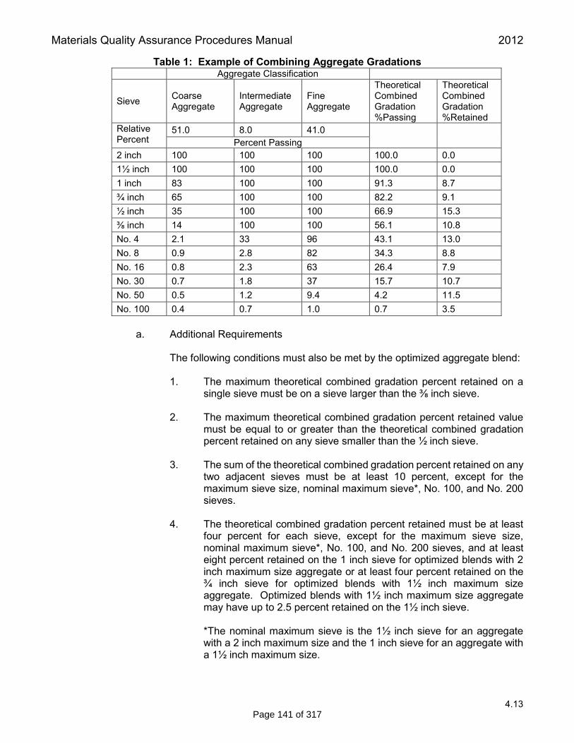
Materials Quality Assurance Procedures Manual 2012
4.13
Table 1: Example of Combining Aggregate Gradations Aggregate Classification
Sieve Coarse Aggregate
Intermediate Aggregate
Fine Aggregate
Theoretical Combined Gradation %Passing
Theoretical Combined Gradation %Retained
Relative Percent
51.0 8.0 41.0 Percent Passing
2 inch 100 100 100 100.0 0.0 1½ inch 100 100 100 100.0 0.0 1 inch 83 100 100 91.3 8.7 ¾ inch 65 100 100 82.2 9.1 ½ inch 35 100 100 66.9 15.3 ⅜ inch 14 100 100 56.1 10.8 No. 4 2.1 33 96 43.1 13.0 No. 8 0.9 2.8 82 34.3 8.8 No. 16 0.8 2.3 63 26.4 7.9 No. 30 0.7 1.8 37 15.7 10.7 No. 50 0.5 1.2 9.4 4.2 11.5 No. 100 0.4 0.7 1.0 0.7 3.5
a. Additional Requirements
The following conditions must also be met by the optimized aggregate blend:
1. The maximum theoretical combined gradation percent retained on a
single sieve must be on a sieve larger than the ⅜ inch sieve.
2. The maximum theoretical combined gradation percent retained value must be equal to or greater than the theoretical combined gradation percent retained on any sieve smaller than the ½ inch sieve.
3. The sum of the theoretical combined gradation percent retained on any
two adjacent sieves must be at least 10 percent, except for the maximum sieve size, nominal maximum sieve*, No. 100, and No. 200 sieves.
4. The theoretical combined gradation percent retained must be at least
four percent for each sieve, except for the maximum sieve size, nominal maximum sieve*, No. 100, and No. 200 sieves, and at least eight percent retained on the 1 inch sieve for optimized blends with 2 inch maximum size aggregate or at least four percent retained on the ¾ inch sieve for optimized blends with 1½ inch maximum size aggregate. Optimized blends with 1½ inch maximum size aggregate may have up to 2.5 percent retained on the 1½ inch sieve.
*The nominal maximum sieve is the 1½ inch sieve for an aggregate with a 2 inch maximum size and the 1 inch sieve for an aggregate with a 1½ inch maximum size.
Page 141 of 317

Materials Quality Assurance Procedures Manual 2012
4.13
2. Coarseness Factor
Use the optimized aggregate blend and the following formula to calculate a Coarseness Factor (CF).
[combined % retained on 3/8 inch sieve and above]
CF = X 100 [combined % retained on No.8 sieve and above]
Example (see Table 1):
10.8+15.3+9.1+8.7
CF = X 100 = 66.8 ≈ 67 8.8+13.0+10.8+15.3+9.1+8.7
3. Workability Factor
Use the optimized aggregate blend and the following formula to calculate a Workability Factor (WF).
WF* = Combined % Passing No.8 Sieve
Example (see Table 1):
WF = 34.3 ≈ 34
*Increase the calculated WF by 2.5 percent for each increase of 94 pounds of cementitious material over 564 pounds per cubic yard.
4. CF vs. WF Chart
Plot the coarseness factor vs. workability factor (CF calculated in subsection 4.13.04.D.2 and the WF calculated in subsection 4.13.04.D.3) on the CF vs WF chart (see Figure 1).
a. Job Mix Formula (JMF) Zone
The Contractor’s initial proposed optimized aggregate gradation to be used in production, as submitted to the Engineer in the Initial Mix Design, must plot within the Job Mix Formula Zone Boundary of the CF vs WF chart (see Figure 1).
b. Operating Zone
The Contractor must not use an optimized aggregate gradation for production that plots outside of the Operating Zone Boundary (Suspension Limit Boundary) of the CF vs WF chart (see Figure 1).
5. Loss by Wash (LBW)
The Loss by Washing (MTM 108) for each coarse, intermediate and fine aggregate must be according to subsection 4.13.03.A of this procedure.
Page 142 of 317

Materials Quality Assurance Procedures Manual 2012
4.13
6. Finalized Combined Gradation Report
The Contractor must submit to the Engineer a report containing the individual gradation analysis report for each course, intermediate, and fine aggregate, and the Combined Aggregate Gradation documentation (see Table 1) and corresponding Coarseness Factor and Workability Factor charts (see Figure 1) with each Job Mix Formula for the Engineers approval prior to concrete production.
7. Prior to initial startup, the Engineer may sample the on-site production stockpiles for coarse, intermediate, and fine aggregate to verify the optimized aggregate gradation in accordance with subsection 4.13.04 of this procedure.
Figure 1: CF vs WF Chart
4.13.05. Process Control During Concrete Production
A. Production Gradation
A Production Gradation is a combined aggregate gradation (described in section 4.13.04 of this procedure) that is used during concrete production.
Aggregate samples must be taken from the production face of each aggregate stockpile using the mini-stockpile method in accordance with MTM 107.
Ensure that all coarse, intermediate, and fine aggregate samples are free of excess moisture (free moisture) prior to individually combining and subsequently reducing samples of aggregate to testing size.
Page 143 of 317

Materials Quality Assurance Procedures Manual 2012
4.13
Perform a mechanical analysis for each individual aggregate in accordance with MTM 109 utilizing the sieve nest listed in subsection 4.13.04.B.2 of this procedure. Verify the Loss by Washing of each aggregate in accordance with MTM 108. 1. Produce aggregate batch weights to reflect most current Production Gradation results.
a. Concrete Paving Using On-Site Batch Plant. The Contractor must produce
one Production Gradation prior to initial startup and one randomly during each subsequent day of production, thereafter, that represents materials to be used during the next day’s production. When approved by the Engineer, projects using 20 cubic yards or less of concrete per day (reduced production) may reduce the subsequent random Production Gradation frequency to one test per week of production. If additional aggregate is to be added to the production stockpile during the period of reduced production, it must be sampled and tested by the Contractor for compliance prior to inclusion into the production stockpile, or physically separated from the current production stockpile until such a time when it can be sampled and tested for compliance. Production Gradation must meet the requirements for optimized aggregate gradation described in subsection 4.13.04 of this procedure. Each of these Production Gradations must be performed and completed, including aggregate proportion adjustments, to ensure that the CF vs WF will plot within the Action Limits Boundary (see subsection 4.13.05.B of this procedure) prior to use.
b. Concrete Production Using Commercial Batch Plant. If the aggregates are
being provided by aggregate sources meeting the requirements of the Department’s Prequalified Aggregate Supplier Program, the Contractor may utilize the aggregate source’s current weekly gradation analysis reports to maintain gradation quality control of daily concrete production for the combined aggregate proportions. Prior to initial startup and at least weekly during concrete production, thereafter, each of the designated on-site production stockpiles for coarse, intermediate, and fine aggregate must be sampled and tested by the Contractor to verify that the combined aggregate gradation for the JMF will plot within the Operating Zone Boundary (Suspension Limit Boundary) of the CF vs WF chart described in subsection 4.13.04.D.4.b of this procedure. If the Contractor provides documentation to the Engineer verifying an ongoing history of reasonable conformance between the on-site production stockpile gradation test results and the aggregate source’s weekly gradation analysis reports, the Engineer may permit the frequency of weekly stockpile quality control testing to be further reduced for quantity of concrete produced during weeks of reduced production (20 cubic yards or less of concrete per day). The Contractor’s proposed reduced frequency of on-site production stockpile quality control testing must then be approved by the Engineer at the preproduction meeting and documented in the Contractor’s Quality Control Plan. Production Gradation must meet the requirements for optimized aggregate gradation described in subsection 4.13.04 of this procedure. Aggregate proportion adjustments may then be required to ensure that the CF vs WF will plot within the Action Limit Boundary (see subsection 4.13.05.B of this procedure). If the current weekly gradation analysis reports for the aggregate sources meeting the requirements of the Department’s Prequalified Aggregate Supplier Program are not available or the aggregates are being provided by aggregate sources not meeting the requirements of the Department’s Prequalified
Page 144 of 317

Materials Quality Assurance Procedures Manual 2012
4.13
Aggregate Supplier Program, the aggregates must be sampled at the batch plant, tested by the Contractor for compliance and approved by the Department prior to initial startup and at least weekly during concrete production, thereafter. If additional aggregate is delivered to the concrete production facility, it must be either sampled and tested by the Contractor for compliance prior to inclusion into the production stockpile or physically separated from the current production stockpile until such a time when it can be sampled and tested for compliance. Production Gradation must meet the requirements for optimized aggregate gradation described in subsection 4.13.04 of this procedure. Aggregate proportion adjustments may then be required to ensure that the CF vs WF will plot within the Action Limit Boundary (see subsection 4.13.05.B of this procedure).
A moving average of the two most recent and consecutive initial startup and daily random Production Gradations may be used to represent the materials to be used during the next day’s production.
2. The Contractor must provide a Production Gradation Report verifying the completion,
and results, of a Production Gradation to the Engineer prior to any production for that day. The Contractor must also provide a Production Gradation Report to the Engineer for any additional Production Gradation performed under the Contractor’s Quality Control (see subsection 4.13.06.A.1.b of this procedure).
a. The Production Gradation Report must include, but is not limited to, the
following:
1. Contract Number (Control Section/Job Number)
2. Name of Contractor
3. Date of Sampling and Testing and date test represents
4. Individual aggregate gradations
5. Combined aggregate gradations including the Theoretical Combined Gradation Percent Retained for each sieve (see Table 1)
6. Optimized aggregate proportions – report in relative percentages and
resulting batch weights
7. CF and WF calculations
8. Signed by a responsible representative of the Contractor
B. Corrective Action Limits
1. Action Limits must be determined and documented by the Contractor in the Quality Control Plan. Action Limits must not extend beyond the Operating Zone Boundary (Suspension Limit Boundary) described in subsection 4.13.04.D.4.b of this procedure (see Figure 2). Any Production Gradation (subsection 4.13.05.A of this procedure) that plots outside of the Action Limits will require the Contractor to perform all necessary corrective actions detailed in the Quality Control Plan (see subsection 4.13.06.A.1.c of this procedure) to return to within the documented Action Limits
Page 145 of 317

Materials Quality Assurance Procedures Manual 2012
4.13
Boundary. The Contractor must notify the Engineer whenever the process approaches an Action Limit.
C. Suspension of Work Limits
1. The Contractor must stop production and perform all necessary corrective actions detailed in the Quality Control Plan (see subsection 4.13.06.A.1.c of this procedure) to return to within the documented Action Limits Boundary if any Production Gradation (subsection 4.13.05.A of this procedure) has a plotted CF vs WF value that is outside the Operating Zone Boundary (Suspension Limit Boundary) described in subsection 4.13.04.D.4.b of this procedure. The Contractor must notify the Engineer whenever the process approaches a Suspension Limit.
After corrective action has been performed, a new Production Gradation (subsection 4.13.05.A of this procedure) must be established to verify that the corrective actions were successful. Production will not be allowed to continue until a new Production Gradation (subsection 4.13.05.A of this procedure) results in a CF vs WF that plots within the Action Limits Boundary. This new Production Gradation (subsection 4.13.05.A of this procedure) must then be used for process control and a new Production Gradation Report must be given to the Engineer.
2. The Contractor must stop production, perform all necessary corrective actions detailed
in the Quality Control Plan (see subsection 4.13.06.A.1.c of this procedure), and notify the Engineer and Region Materials Supervisor if any combined individual gradation (see subsections 4.13.04.A and 4.13.04.B of this procedure) does not meet the requirements described in section 4.13.07 of this procedure. Resume production only after receiving a Notice to Resume Work (Form 1165) from the Engineer.
Page 146 of 317

Materials Quality Assurance Procedures Manual 2012
4.13
Figure 2: CF vs WF with Action Limits
4.13.06. Quality Control for Optimized Aggregate Gradation
A. Quality Control Plan
1. Elements of the Plan
The plan must address all elements that affect the quality of the aggregate, including but not limited to, the following:
a. Stockpile management (see subsection4.13.03.B.2 of this procedure).
b. The frequency of sampling and testing including additional Production
Gradation beyond the minimum required in subsection 4.13.05.A.1 of this procedure.
c. Corrective Actions
1. Corrective actions to be taken when CF vs WF is outside of Action
Limits Boundary.
2. Corrective actions to be taken when CF vs WF is outside of Operating Zone Boundary (Suspension Limit Boundary).
3. Corrective actions to be taken when an averaged gradation is non-
compliant with section 4.13.07 of this procedure.
Page 147 of 317

Materials Quality Assurance Procedures Manual 2012
4.13
d. Methods for verifying Production Gradations.
B. Documentation
The Contractor must maintain records of all inspections and tests. The records must indicate the nature and number of observations made, the number and type of deficiencies found, the quantities represented by the test, and any corrective action taken. Copies must be submitted to the Engineer as work progresses.
1. A control chart and running tabulation of individual test results must be prepared for
the following tests. These must be available to the Engineer at any time and submitted to the Engineer weekly in a format acceptable to the Engineer, including:
a. Gradations for both individual and combined aggregates
b. Moisture content of aggregates
c. Coarseness Factor
d. Workability Factor
2. Submit within 24 hours of sampling a copy of all documentation for each Production
Gradation to the Engineer; including a copy of the respective Production Gradation Report (see subsection 4.13.05.A.2 of this procedure). Report coarse, intermediate, and fine aggregate proportions from each Production Gradation in relative percentage and resulting batch weights for each aggregate. Attach a copy of all respective concrete production batch tickets to the documentation for each Production Gradation.
C. Non-Compliant Materials
The Contractor must establish and maintain an effective and positive system for controlling non-compliant materials, including procedures for their identification, isolation and disposal. Reclaiming or reworking of non-complying materials must be in accordance with procedures acceptable to the Engineer.
All non-compliant materials and products must be separated and clearly identified to prevent use, shipment, and contamination with conforming materials.
The Contractor must take prompt action to correct and document conditions that have resulted, or could result, in the incorporation of non-compliant materials and update the Quality Control plan if necessary.
D. All sampling and testing performed under the Contractor’s Quality Control Plan for optimized
aggregate gradation must be performed by a Michigan Certified Aggregate Technician (MCAT). Each quality control person performing quality control sampling of aggregates on the project will be required to demonstrate to MCAT certified Department personnel proper sampling of course, intermediate and fine aggregate prior to batching concrete. The sampling will be conducted at the concrete batching facility. Aggregate samples will be taken from the production face of each aggregate stockpile using the mini-stockpile method according to MTM 107.
Page 148 of 317

Materials Quality Assurance Procedures Manual 2012
4.13
4.13.07. Aggregate Physical Properties Reports
A. Prior to the pre-production meeting, the Contractor must submit test reports from the aggregate producer verifying that the aggregates meet the physical requirements of this procedure. The reports must include, but are not limited to:
1. Coarse Aggregate:
- Freeze-thaw Report (MDOT report) - Flat and Elongation Report (Aggregate Producer report) - Mechanical Analysis (Aggregate Producer report)
• Includes Gradation, Loss By Washing and Deleterious results • Deleterious results will include at least the following: Soft Particles %, Chert
Particles %, Sum of Soft and Chert %, sum of Coke and Coal %, and Clay-Ironstone %
2. Intermediate Aggregate:
- Freeze-thaw Report (MDOT report) - Mechanical Analysis (Aggregate Producer report)
• Includes Gradation, Loss By Washing, and Deleterious results • Deleterious results include at least the following: Soft Particles %, Chert
Particles %, Sum of Soft and Chert %, sum of Coke and Coal %, and Clay-Ironstone %
3. Fine Aggregate:
- Organic Impurities results (Aggregate Producer report) - Mechanical Analysis (Aggregate Producer report)
• Includes Gradation, Loss By Washing, and Fineness Modulus 4.13.08. Acceptance During Concrete Production
A. Acceptance of the coarse, intermediate and fine aggregates will be conducted in accordance with the Department’s Procedures for Aggregate Inspection, except for the following:
1. Each individual production stockpile of intermediate and fine aggregate will be
sampled at the same time as the corresponding coarse aggregate and tested concurrently, regardless of the individual quantities of intermediate and fine aggregate that have been used, to date, for the optimized aggregate mixture at the time the coarse aggregate is sampled.
a. Concrete Paving Using On-Site Batch Plant. The minimum sampling and
testing frequency for each individual aggregate will be one per 5,000 tons of coarse aggregate used in the optimized aggregate mixture (one per project for projects less than 5,000 tons).
b. Concrete Production Using Commercial Batch Plant. As determined by the Engineer at the preproduction meeting, the minimum sampling and testing frequency for each individual aggregate will be based on either of the following criteria:
Page 149 of 317

Materials Quality Assurance Procedures Manual 2012
4.13
1. Quantity of Aggregate Used. The minimum sampling and testing frequency for each individual aggregate will be one per 5,000 tons of coarse aggregate used in the optimized aggregate mixture (one per project for projects less than 5,000 tons). For optimized aggregate mixtures that include one or more non-prequalified aggregate sources, the minimum sampling and testing frequency will be increased to ensure that all non-prequalified aggregates will be sampled and tested at a minimum frequency of one per 1,000 tons (one per project for projects less than 1,000 tons).
2. Volume of Concrete Produced. The minimum sampling and testing frequency for each individual aggregate will be one per 2,000 cubic yards of concrete produced for each Grade of concrete utilizing optimized aggregate gradations (minimum one per project per Grade of concrete).
2. Sampling for acceptance will be conducted at the concrete batching facility. Aggregate
samples will be taken from the production face of each aggregate stockpile using the mini-stockpile method in accordance with MTM 107.
3. The Department will perform a mechanical analysis for each individual aggregate in
accordance with MTM 109 utilizing the sieve nest listed in subsection 4.13.04.B.2 of this procedure.
a. The Department will verify the Loss by Washing of each aggregate in
accordance with MTM 108. Acceptance will be based on the Loss by Washing requirements specified in subsection 4.13.03.A of this procedure.
b. The Department will verify the ability of the aggregates to be optimized. The
mechanical analyses generated from the acceptance tests for each individual coarse, intermediate, fine aggregate will be compared to those provided by the Contractor that were used to generate the actual Production Gradation for the concrete representing the period of production when the acceptance samples were obtained. Acceptance of the combined aggregate gradation will be based on the ability of the combined aggregate gradation to plot within the Operating Zone Boundary (Suspension Limit Boundary) of the CF vs WF chart described in subsection 4.13.04.D.4.b of this procedure, using the mechanical analysis acceptance test results obtained in subsection 4.13.08.A.3 of this procedure, proportioned in their respective relative percentages as provided by the Contractor, above.
Page 150 of 317