materials technology for coal-conversion processes
TRANSCRIPT

ANL-80-46
"1MASTER ANL-80-46
MATERIALS TECHNOLOGY FOR
COAL-CONVERSION PROCESSES
Progress Report for
January-March 1980
ARGONNENATIONAL
LABORATORY
ARGONNE NATIONAL LABORATORY. ARGONNE, ILLINOIS
Prepared for the Office of Fossil Energy
U. S. DEPARTMENT OF ENERGYW-31-109-Eng-38under Contract

Distribution Categories:Coal Conversion and Utilization:
Coal Gasification (UC-90c)Direct Combustion of Coal (UC-90e)Materials and Components (UC-90h)
ANL-80-46
ARGONNE NATIONAL LABORATORY9700 South Cass Avenue
Argonne, Illinois 60439
MATERIALS TECHNOLOGY FORCOAL-CONVERSION PROCESSES
Progress Report forJanuary-March 1980
William A. EllingsonProgram Manager
Materials Science Division
June 1980
DISCLAIMER
Most recent reports in this series
ANL-79-23ANL-79-56ANL-79-93ANL-80-12
October-DecemberJanuary-March
Apri 1-JuneJuly-December
1978197919791979


TABLE OF CONTENTS
HIGHLIGHTS........... . ......... . . . .
FOREWORD.. ............ . ... .........
ABSTRACT ....... . ......... .... ....
INTRODUCTION.. .. ..... ...........
Task A -- Evaluation of Ceramic Refractories for SlaggingGasifiers . . . . . . . . . . . .
1. Fused-cast Alumina (Number 2)
2. Sintered Alumina-Chromia (Number 16) . . . . . . . .
3. Sintered Alumina-Chromia (Number 852)
4. Fused-cast Alumina-Chromia (:umber 280)
5. Fused-cast Magnesia-Spinel (Number 317)
6. Sintered Magnesia-Chrome (Number 35) .... .. ..
Task C -- Development and Application of Nondestructive EvaluationMethods for Coal-conversion Processes
1. Erosive Wear: Detection and Monitoring..
a. Metallic Transfer Lines . . . . . . . . . . . . . .
(') ' t'a;oni Stclie - Pilot '!anuto7 . . . . . .
(a) Solvent Refined Coal Liquefaction Plant
(h) Morgantown Energy Technology CenterGasification Plant
2. Refractory Tnstallation Practices
a. Detection of Thermally Induced Acoustic Emissionsfrom Refractory Concrete Materials . . . . . .
3. Component Inspection . . . . .... . . . . . . . .
a. Acoustic Monitoring of Valves . . . . . . . . .
iii
Page
vii
ix
ix
. . 1
.. 1
.. 1
1
" 2
. . 2
14
14
14
14
14
15
21
21
21
21
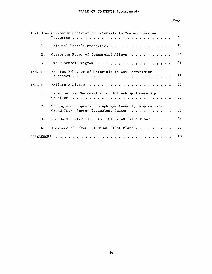
TABLE OF CONTENTS (continued)
Page
Task
Task
Task
REFERENCES
iv
D -- Corrosion Behavior of Materials in Coal-conversionProcesses. . . . . . . . . . . . . . . . . . . . . . . .
1. Uniaxial Tensile Properties.. . . . . . . . . . . . . .
2. Corrosion Rates of Commercial Alloys
3. txperimentaliProgram
E -- erosion Behavior of Materials in Coal-conversionProcesses . . . . . . . . . . . . . . . . . . . . . . . .
-- Failure Analysis . . . . . . . . . . . . . . . . . . . .
1. Experimental Thermowells for IGT Ash AgglomeratingGasifier . . . . . . . . . . . .
2. Tubing and Compre!sor Diaphragm Assembly Samples fromGrand forks Energy Technology Center . . . . . . . . . .
3. Solids Transfer Line from !GT HYGAS Pilot Plant . . . . .
4. Thermocouple from ICT HYCAS Pilot Plant . .. ..... .
21
21
22
24
33
35
35
35
2 0
37
40.0
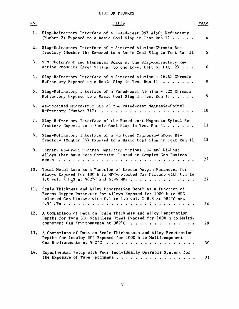
LIST OF FIGURES
No. Title Page
1. Slag-Refractory Interface of a Fused-cast 99% Al203 Refractory
(Number 2) Exposed to a Basic Coal. Slag in Test Run 11 . . . . . 4
2. Slag-Refractory Interface of c Sintered Alumina-Chromia Re-fractory (Number 16) Exposed to a Basic Coal Slag in Test Run 11 5
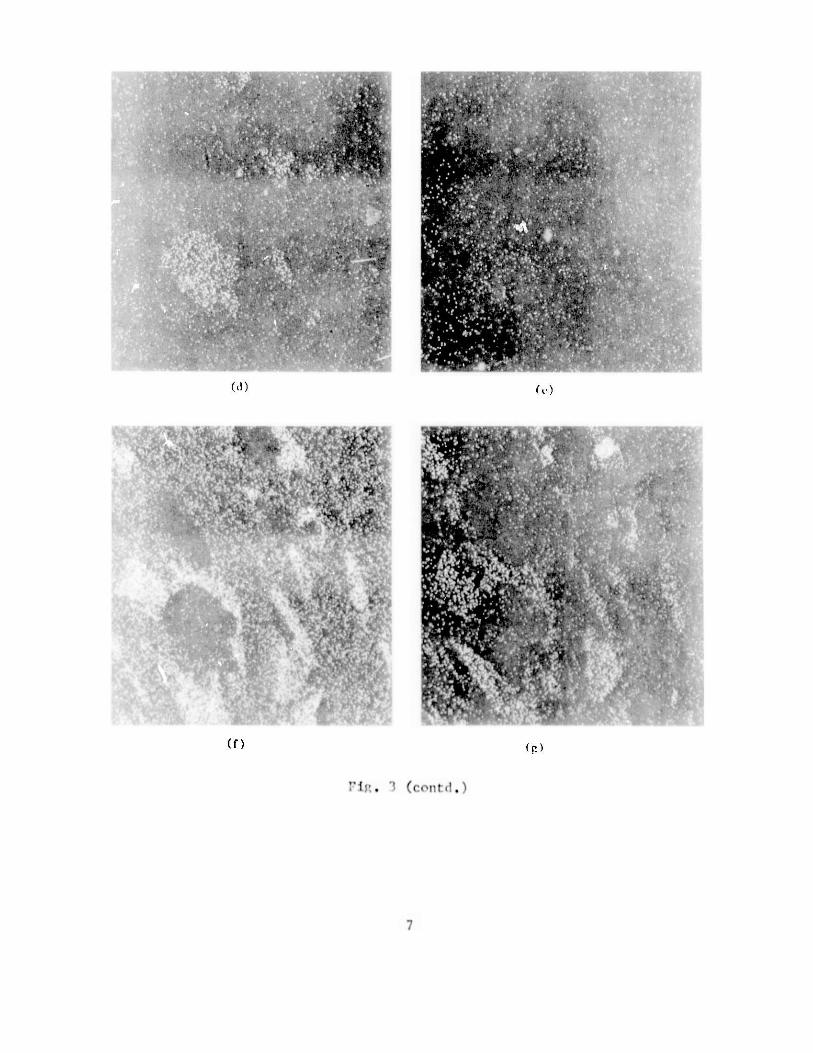
3. SEM Photograph and Elemental Scans of the Slag-Refractory Re-action Products (Area Similar to the Lower Left of Fig. 2) . . . 6
4. Slag-Refractory Interface of a Sintered Alumina - 16.6% ChromiaRefractory Exposed to a Basic Slag in Test Run 11 . . . . . . . 8
5. Slag-Refractory Interface of a Fused-cast Al'mina - 32% ChromiaRefractory Exposed to a Basic Coal Slag in Test Run 11 . . . . . 9
6. As-received Microstructure of the Fused-cast Magnesia-SpinelRefractory (Number 317) . . . . . . . . . . . . . . . . .. . . 10
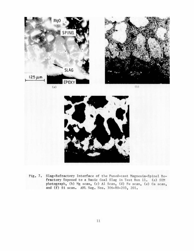
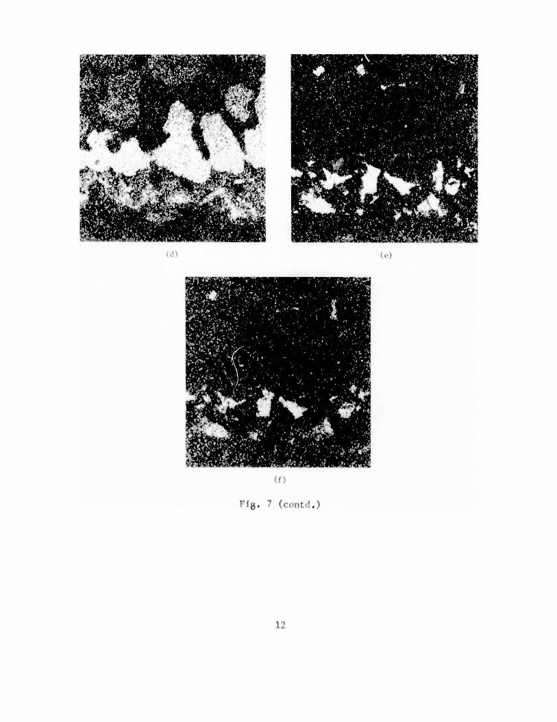
7. Slag-Refractory Interface of the Fused-cast Magnesia-Spinel Re-fractory Exposed to a Basic Coal Slag in Test Rut1 11 . . . . . . 11
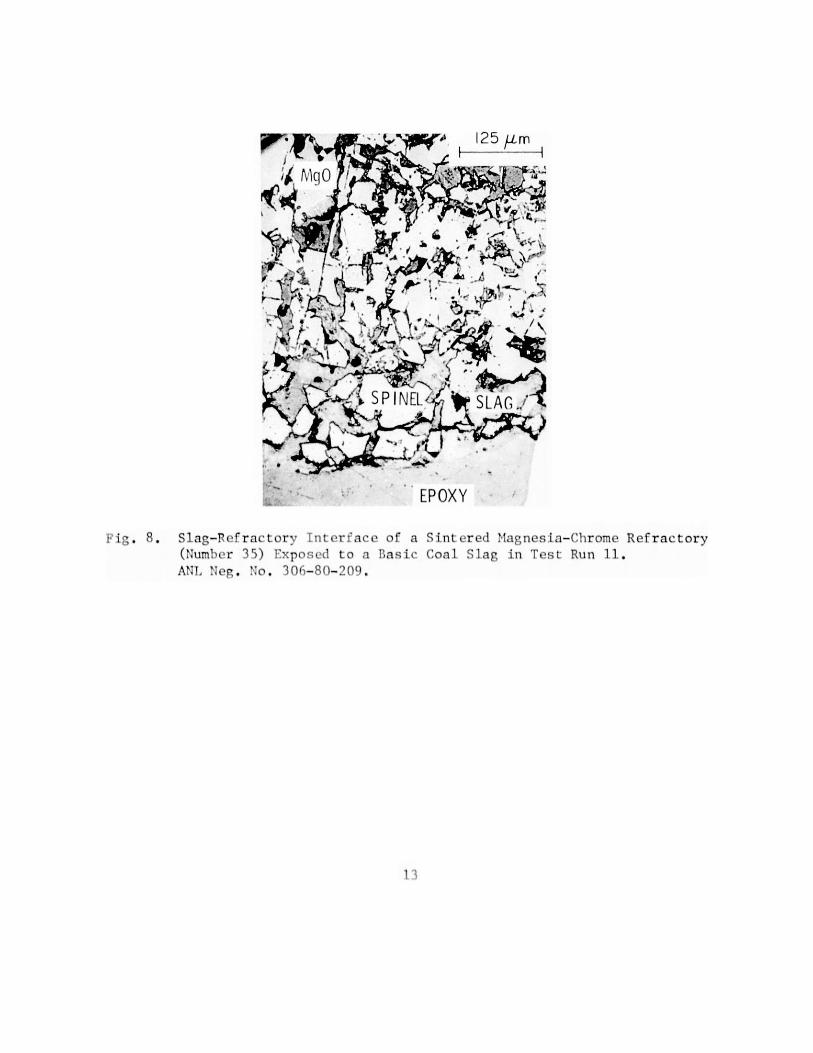
8. Slag-Refractory Interface of a Sintered Magnesia-Chrome Re-fractory (Number 35) Fxposed to a Basic Coal slag in Test Run 11 13
9. Ternary Fe-Cr-Ni I)irgram Depicting Various Fe- and Ni-baseAlloys that have been Corrosio:i Tested in Complex Gas Environ-ments . . . . . . . . . . . . . . . . . . . . . . . . . . . . 27
10. Total Metal Loss as a Function of Excess Oxygen Parameter forAlloys Exposed for 100 h to MPC-selected Gas Mixture with 0.1 to1.0 vol. %HIS at 982*C and 6.94 MPa . . . . . . . . . . . . . . 27
11. Scale Thickness and Alloy Penetration Depth as a Function ofExcess Oxygen Parameter for Alloys Exposed for 1000 h to MPC-selected Gas Mixture with 0.1 to 1.0 vol. % HS at 982*C and6.94 J Pa . . . . . . . . . . . . . . . . . . . . . . . . . . . . 28
12. A Comparison of Data on Scale Thickness and Alloy PenetrationDepths for Type 310 Stainless Steel Exposed for 1000 h to Multi-component Gas Environments at 982 C . . . . . . . . . . . . . . 29
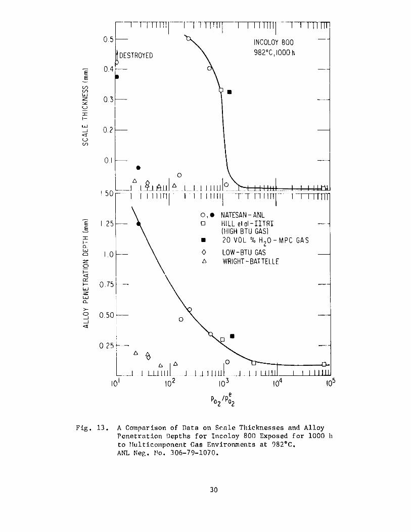
13. A Comparison of Data on Scale Thicknesses and Alloy PenetrationDepths for Incoloy 800 Exposed for 1000 h to MulticomponentGas Environments at 982 C . . . . . . . . . . . . . . . . . . . 30
14. Experimental Setup with Four Individually Operable Systems forthe Exposure of Tube Specimens . . . . . . . . . . . . . . . . . 31
V
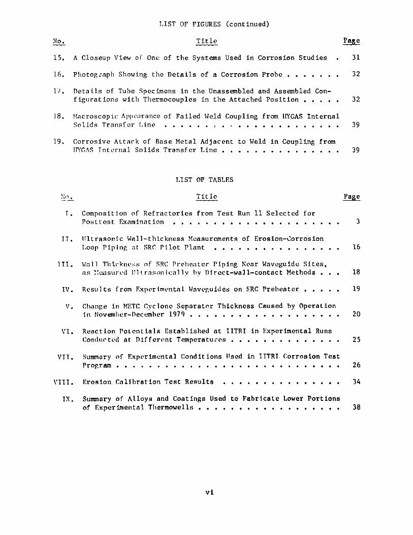
LIST OF FIGURES (continued)
No. Title Page
15. A Closeup View of One of the Systems Used in Corrosion Studies . 31
16. Photograph Showing the Details of a Corrosion Probe . . . . . . . 32
1/. Details of Tube Specimens in the Unassembled and Assembled Con-figurations with Thermocouples in the Attached Position . . . . . 32
18. Macroscopic Appearance of Failed Weld Coupling from HYGAS InternalSolids Transfer Line . . . . . . , . . . . . . . . . . . . . . . 39
19. Corrosive Attack of Base Metal Adjacent to Weld in Coupling fromTTYCAS Internal Solids Transfer Line . . . . . . . . . . . . . . . 39
LIST OF TABLES
No. Title Page
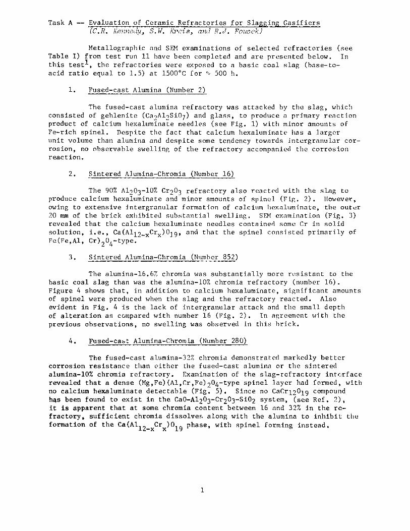
T. Composition of Refractories from Test Run 11 Selected forPosttest Examination . . . . . . . . . . . . . . . . . . . . . 3
IT. Ultrasonic Wall-thickness Measurements of Erosion-CorrosionLoop Piping at SRC Pilot Plant . . . . . . . . . . . . . . . . 16
III. Wall Thickness of SRC Prelhenter Piping Near Waveguide Sites,
as esured Ulltrasonicallv by Direct-wall-contact Methods . . . 18
IV. Results from Experimental Waveguides on SRC Preheater . . . . . 19
V. Change in METC Cyclone Separator Thickness Caused by OperationIn November-December 1979 . . . . . . . . . . . . . . . . . . . 20
VI. Reaction Potentials Established at IITRI in Experimental RunsConducted at Different Temperatures . . . . . . . . . . . . . . 25
VIT. Summary of Experimental Conditions Used in IITRI Corrosion TestProgram . . . . . . . . . . . . . . . . . . . . . . . . . . . . 26
VIII. Erosion Calibration Test Results . . . . . . . . . . . . . . . 34
IX. Summary of Alloys and Coatings Used to Fabricate Lower Portionsof Experimental Thermowells . . . . . . . . . . . . . . . . . . 38
vi
MATERIALS TECHNOLOGY FOR COAL-CONVERSION PROCESSESProgress Report forJanuary-March 1980
HIGHLIGHTS
Task A -- Evaluation of Ceramic Refractories for Slagging Gasifiers(C. R. Kenndy, S. W. Kroin, and R.J. Fcusek )
The mechanisms responsible for the corrosion of the refractoriesfrom test run 11 have been identified using SEM and metallography. The high-alumina refractory reacted with the basic slag to produce calcium hexaluminate.
As the chromia content of the alumina-chromia refractories increased from 10to 32%, the primary reaction product changed from calcium hexaluminate to
spinel, and the corrosion resistance was markedly increased. Free magnesia in
the magnesia-chrome and magnesia-spinel refractories was preferentially
dissolved.
Test run 12 has nearly been completed. This test will evaluate thecompatibility of a high-iron oxide acid slag with chrome-containing re-
fractories.
Task C -- Development and Application of Nondestructive Evaluation Methodsfor Coal-conversion Processes (W.A. Z'7 7inqson: znd ''.A. Youngdahll)
The major activity during this period has been further field evalu-ation of the high-temperature ultrasonic erosion scanner. The high-temperaturescanner was operated at the Solvent Refined Coal (SRC) coal liquefactionplant in Tacoma, WA, and data suggested repeatability of system measurementsto be 0.025 mm. Both the SRC and the Morgantown erosion-scanning systems
are now directly connected to automatic, computer-controlled data-acquisitionsystems. Wear data obtained with the scanner at SRC suggest that the wearrate was higher in new 1-1/2-in. piping than in 2-in. piping used simul-taneously in the same line. The 2-in. piping had been exposed previously tothe process stream. The lower rate of wear in the larger pipe is probablya result of a lower stream velocity and the presence of a hard reaction layerthat SRC plant personnel have noted on stainless steel exposed to the high-temperature process fluid. Analysis of a chart record showed that the ANLscanner at Morgantown successfully monitored wear of the cyclone (maintainedat nominally 540 C) during the run of November-December 1979.
Final arrangements were made with Exxon to install high-temperatureerosion-monitoring equipment at the Baytown, TX coal liquefaction plant.Also, agreement has been reached with Exxon on most of the details regardingfield testing of the passive acoustic system for blockage-valve leak de-tection.
vii
Task D -- Corrosion Behavior of Materials in Coal-conversion Processes(K. Natesan)
The experimental program to evaluate the effect(s) of multicomponent
gas environments on the corrosion and uniaxial tensile properties of four high-
chromium alloys has been completed. The results are being analyzed and will
be summarized in a topical report. A review of the corrosion behavior of
commercially available alloys_ howed that a number of them exhibit acceptible
corrosion rates of t 0.6 mm y , based on 10,000-h exposures to complex gas
mixtures. However, the experiments in these studies were conducted at excess
oxygen-parameter values of ' 103 or higher; the alloys exposed under theseconditions are expected to develop protective oxide scales, and the long
exposures used will only establish the susceptibility of a given alloy tobreakaway corrosion. Data are also needed on the corrosion behavior of ma-
terials in environments with excess oxygen-parameter values below 103, since
most coal-gasification processes will expose materials to a wide range of
oxygen partial pressures.
Experiments have been initiated to develop information on material
behavior in low-Btu gasification and combustion environments for heat-exchanger and gas-turbine applications.
Task E -- Erosion Behavior of Materials in Coal-conversion Processes(J.Y. 7>' (d W.J. Shack)
A room-temperature erosion calibration test was performed on 1015
carbon steel, Type 304 stainless steel, Incoloy 800, RA310 stainless steel,
and Stellite 6B using 100-grit size (150-um) alumina at an impingementvelocity of 22 m/s and angles of 6 tc 360. The erosion rate (mass loss/mass impacted) was found to be 0.03-0.09 mg/g. These results are com-
parable to those obtained by other investigators.
Task F -- Failure Analysis (D.R. Dicreks, S. Greenberg, eJ.Y.N. Wang,7... 4ragoi, and J.E. Slat terry)
Seven experimental thermowells prepared for trial exposure in theICT U-Gas Pilot Plant have been completed and are presently in place awaitingstart-up of that plant. An examination of tubing and compressor diaphragmsamples from the GFETC coal-liquefaction continuous-process unit has beencompleted; cracks were detected in two of the three diaphragm samples ana-lyzed. An extensive investigation of a failed internal solids transfer linefrom the ICT HYGAS Pilot Plant is presently under way. Initial resultsindicate that the failure was due to severe localized sulfidation attack onthe high-nickel Inconel 182 weld metal used to fabricate the line. A failedthermocouple assembly from the HYGAS plant is also being examined, but thecause of failure for this component has not yet been identified.
viii
MATERIALS TECHNOLOGY FOR COAL-CONVERSION PROCESSESProgress Report for
January-March 1980
FOREWORD
This broad-base materials engineering program, begunin 1974, includes studies on ceramic (refractory) and metallic
materials presently being used or intended for use in coal-
conversion processes. The program entails nondestructive
testing, failure analysis, and studies of erosive wear, cor-
rosion, and refractory degradation. Appropriate laboratory and
field experiments are integrated such that the results have
impact on present pilot- and demonstration-plant and proposed
full-scale designs. This report, for the period January-
March 1.980, presents the technical accomplishments of the
program.
ABSTRACT
Analysis of recent refractory-slag interaction tests suggests thatas the chromia content is increased from 10 to 32%, the primary reactionproduct changes from calcium hexaluminate to spinel, significantly increasing
the corrosion resistance of the refractory.
Field reliability of the high-temperature ultrasonic erosionscanner was demonstrated at both a coal liquefaction plant (SRC at Tacoma, WA)
and a coal gasification plant (Morgantown, WV). Continuous high-temperatureoperation has been demonstrated and an accuracy of 0.025 mm seems achievable.
Equipment has been ordered for field tests of passive acousticsystems at Exxon. This includes a four-channel tape recorder, differentialamplifiers, and signal conditioners.
Corrosion studies have been completed on effects of multicomponentgas environments on corrosion mechanisms and uniaxial tensile properties ofFe-Ni-Cr alloys. Results of these and other tests utilizing 10,000-h ex-posures suggest that corrosion rates of 0.6 mm/y can be expected.
Failure analysis activities included studies of compressor dia-phragms from the Grand Forks Energy Technology Center coal-liquefactioncontinuous-process unit. Cracks were found in two of the three diaphragms.Failure of an internal solids transfer line from HYCAS appears to have beencaused by severe localized sulfidation of the high-nickel Inconel 182 weldmetal used to fabricate the line.
In addition to these research activities, program plans were pre-pared and submitted for FY 1981 and FY 1982.
ix
INTRODUCTION
Economical conversion of coal into clean and usable alternatefuels will be advanced through the use of durable materials systems. Thetechnical information base applicable to materials selection in plant designfor the operating environments of various coal-conversion processes isextremely limited. Hence, reliable selection and lifetime-prediction methodsfor materials under these conditions are not available. This program is de-signed to provide part of the materials information necessary for successfuloperation of coal-conversion systems, The present report is the twentieth
progress report submitted by ANL to the Office of Advanced Research andTechnology, Office of Fossil Energy under Project Number 7106, "MaterialsTechnology for Coal-conversion Processes".
The project includes five tasks: (A) Evaluation of commercial re-
fractories exposed to coal slag under conditions typical of those encounteredin slagging gasification processes; (C) development, valuation, and appli-cation of nondestructive evaluation methods for coal-conversion systems;(1)) evaluation of the corrosion behavior of commercial alloys; (E) develop-
ment of analytical models to predict the erosive-wear behavior of materialsused in coal-conversion plants; and (F) analysis of failed coal-conversion
plant components.
x
Task A -- Evaluation of Ceramic Refractories for Slagging Gasifiers(C.R. Kennedy, S.W. Kreis, and R.J. Fouwek)
Metallographic and SEM examinations of selected refractories (seeTable I) from test run 11 have been completed and are presented below. In
this test', the refractories were exposed to a basic coal slag (base-to-
acid ratio equal to 1.5) at 1500 C for % 500 h.
1. Fused-cast Alumina (Number 2)
The fused-cast alumina refractory was attacked by the slag, whichconsisted of gehlenite (Ca2Al2Si07 ) and glass, to produce a primary reaction
product of calcium hexaluminate needles (see Fig. 1) with minor amounts of
Fe-rich spinel. Despite the fact that calcium hexaluminate has a larger
unit volume than alumina and despite some tendency towards intergranular cor-
rosion, no observable swelling of the refractory accompanied the corrosion
reaction.
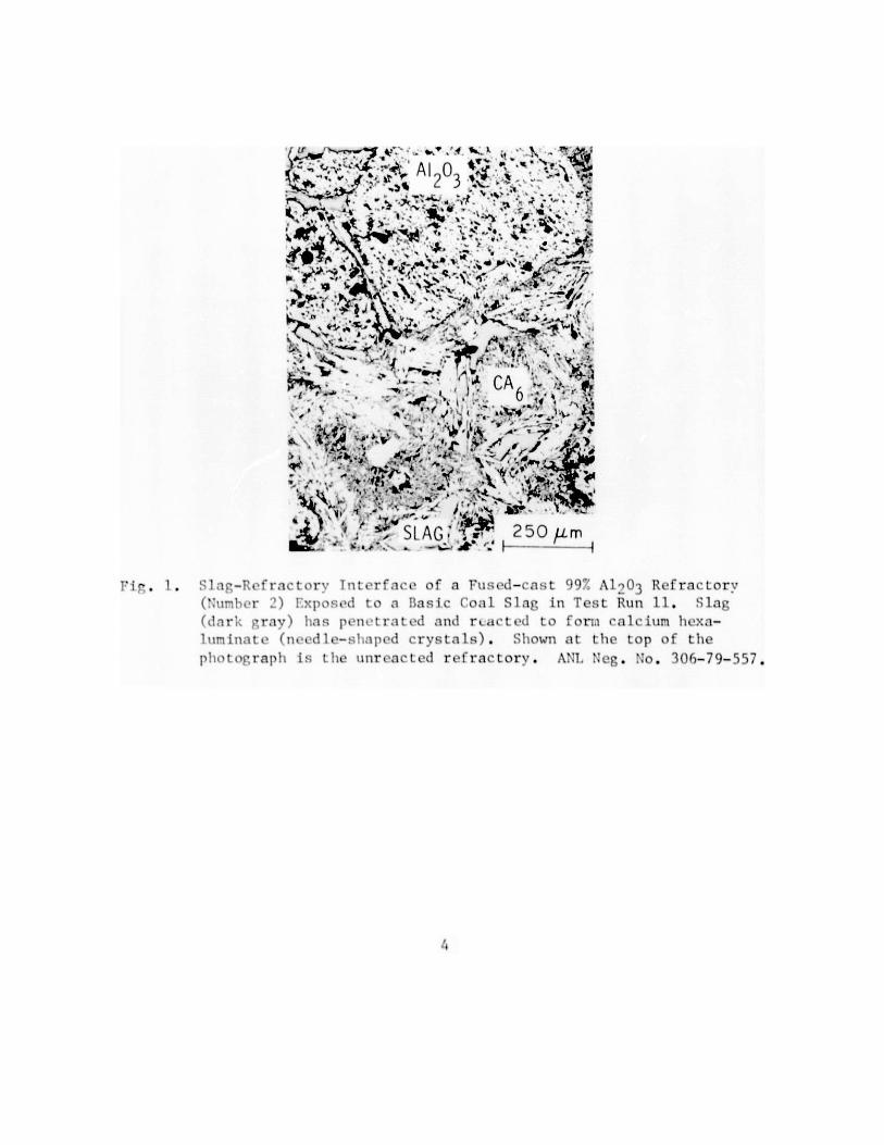
2. Sintered Alumina-Chromia (Number 16)
The 90% A1 2 03 -10% Cr2 03 refractory also reacted with the slag to
produce calcium hexaluminate and minor amounts of spinel (Fig. 2). However,owing to extensive intergranular formation of calcium hexaluminate, the outer
20 mm of the brick exhibited substantial swelling. SEM examination (Fig. 3)revealed that the calcium hexaluminate needles contained some Cr in solid
solution, i.e., Ca(All2-xCrx )019, and that the spinel consisted primarily ofFe(Fe,Al, Cr)204-type.
3. Sintered Alumina-Chromia (Number 852)
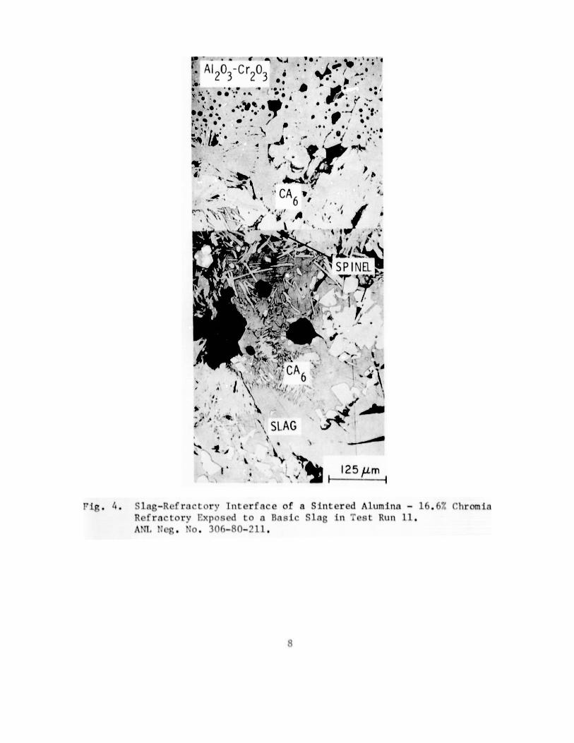
The alumina-16.6% chromia was substantially more resistant to the
basic coal slag than was the alumina-10% chromia refractory (number 16).
Figure 4 shows that, in addition to calcium hexaluminate, significant amountsof spinel were produced when the slag and the refractory reacted. Alsoevident in Fig. 4 is the lack of intergranular attack and the small depth
of alteration as compared with number 16 (Fig. 2). In agreement with theprevious observations, no swelling was observed in this brick.
4. Fused-cast Alumina-Chromia (Number 280)
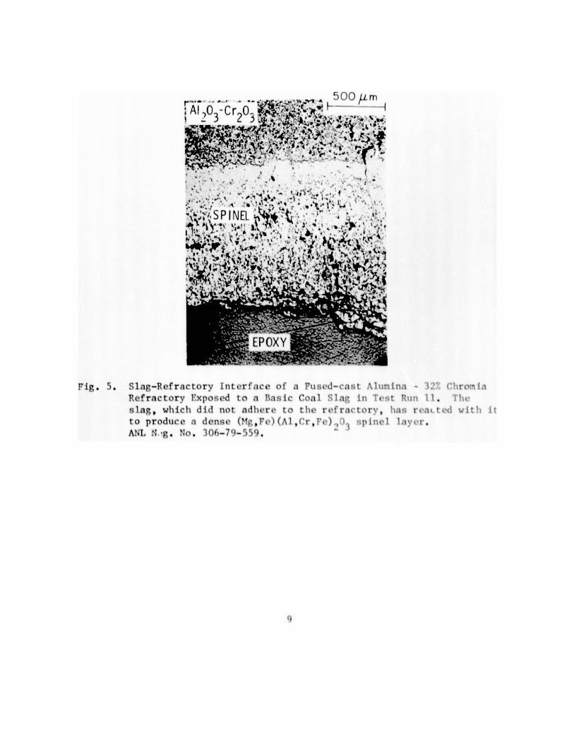
The fused-cast alumina-32% chromia demonstrated markedly bettercorrosion resistance than either the fused-cast alumina or the sintered
alumina-10% chromia refractory. Examination of the slag-refractory interfacerevealed that a dense (Mg,Fe)(Al,Cr,Fe)204-type spinel layer had formed, withno calcium hexaluminate detectable (Fig. 5). Since no CaCr12019 compoundhas been found to exist in the CaO-A1203-Cr203-Si02 system, (see Ref. 2),it is apparent that at some chromia content between 16 and 32% in the re-fractory, sufficient chromia dissolves along with the alumina to inhibit theformation of the Ca(Al Cr )0 phase, with spinel forming instead.
12-x x 19
1

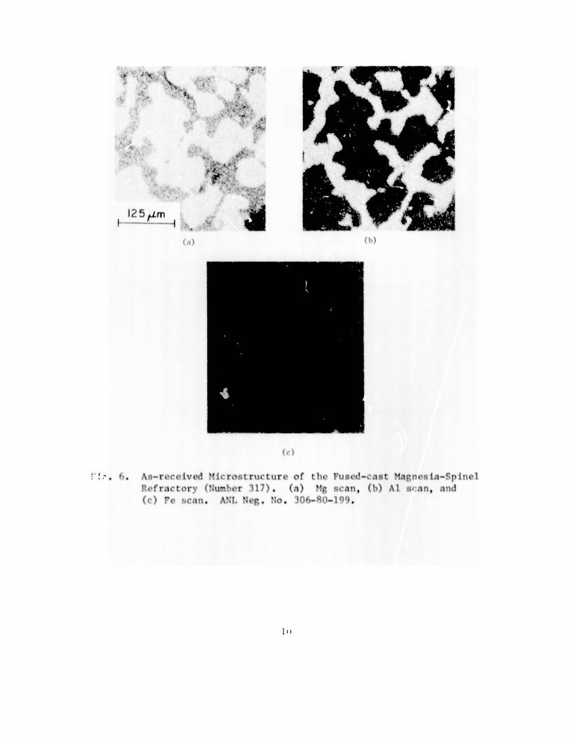
5. Fused-cast Magnesia-Spinel (Number 317)
The as-received microstructure of this material consisted of peri-clase (MgO) grains surrounded by a spinel (MgAl20 4 ) matrix (Fig. 6). Posttestexamination revealed that both phases underwent iron oxide enrichment, andthat the periclase grains appeared to be more readily dissolved by the slagthan the spinel matrix (Fig. 7). It should be noted, however, that theoverall rate of attack was the second highest observed, exceeded only by thecorrosion rate of the chemically bonded Al203-7.5% Cr20 refractory.
6. Sintered Magnesia-Chrome (Number 35)
As in the case of the magnesia-spinel refractory, the free magnesiaappeared to be preferentially attacked by the slag (Fig. 8). Although .ub-stantial penetration by the slag was observed, the chrome-spinel phase washighly' resistant to dissolution, unlike the magnesia-spinel phase in re-fractory number 317, and thus the overall rate of corrosion was low. Irono::ide enrichment of both phases nec'.r the slag-refractory interface was againobserved.
Test run 12, which will evaluate the compatibility of a varietyof chrome-containing refractories with a high-iron oxide (25%) acidic coalslag at 1575*C, was initiated on January 11, 1980. Shortly after the furnacereached operating temperature, a failure of a natural-gas flowmeter sight
glass caused an automatic shutdown. Because of the potentially seriousnature of this failure, a safety review of the apparatus and control systemswas conducted. As a result of this review, new types of flowmeters were
installed in the natural-gas lines and additional air-flow sensors wereincorporated into the automatic shutdown system. An inspection of the
refractories revealed that serious corrosion had already occurred in two
types of carbon-impregnated brick after only t 36 h at 1575*C. These re-fractories were removed from the unit and replaced with conventional alumina-chromia refractories. The furnace was restarted on February 22 but a leak ina water flowmeter caused a loss of cooling water to a burner and resulted in
another shutdown on February 23. Examination of the burner revealed that it
also had developed a leak, which had to be repaired. The furnace wasstarted for the third time on March 25.
2
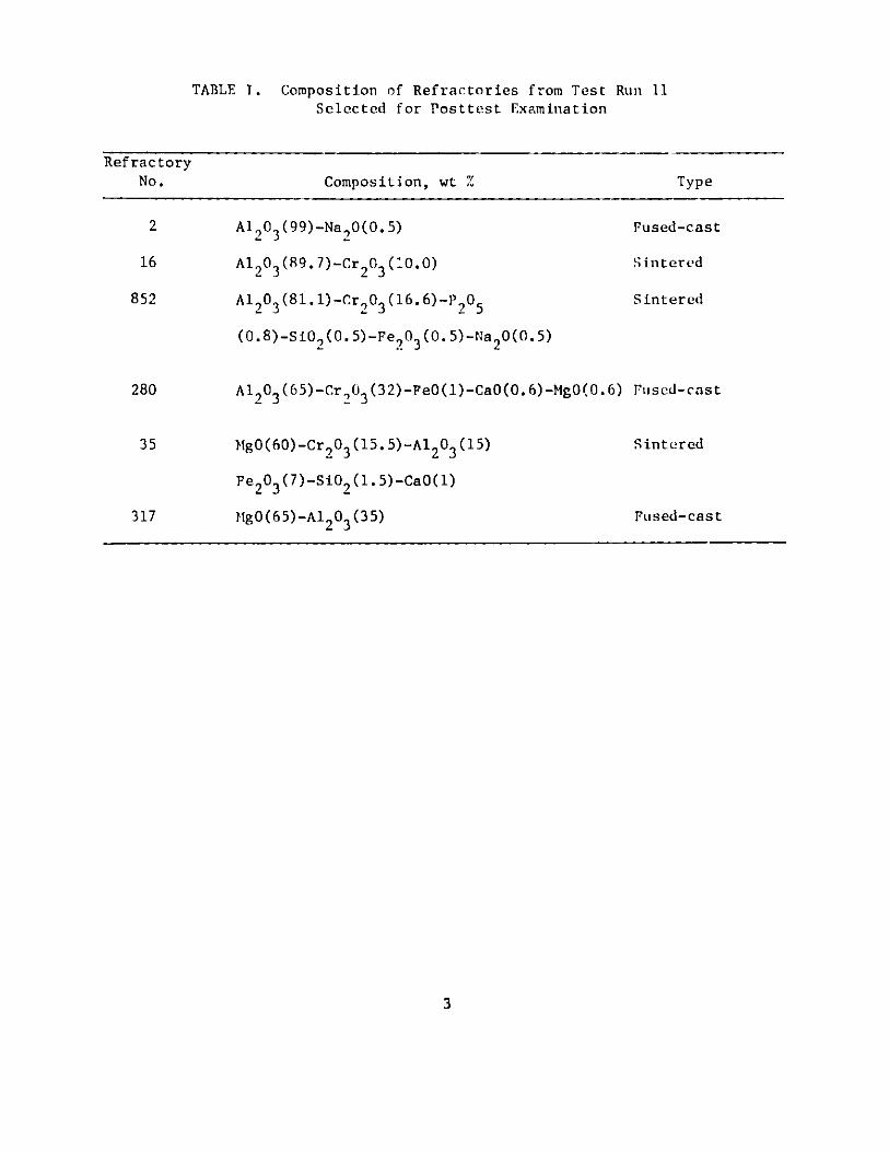
TABLE I. Composition of Refractories from Test Run 11Selected for Posttest Examination
RefractoryNo. Composition, wt %
A120 3 (99)-Na,,0(0.5)
Al203 (89.7)-Cr 2 0 3 (0.0)
Al 203 (81.1)-Cr203(16.6)-P9 05(0.8)-S102(0.5)-Fe 9 03 (0.5)-Na 2 0(0.5)
Fused-cast
S intered
Sintered
Al20 3 (65)-Cr 2 03(32)-Fe0(1)-CaO(0. 6)-MgO(0.6) Fused-cast
2
16
852
280
35
317
Sintered
Fused-cast
3
Type
MgO(60)-Cr 9 0 3(15.5)-A1 2 03 (15)
Fe203 (7)-S102 (1.5)-CaO(1)
MgO(65)-A1 2 0 3 (35)
Al 0
' M+
CA
*- 40
:r S 4 AG 250 ptm
F . . S g- fractLory" 1nt orf arc of a Ftur d-ratit O97' A\ 103 R f rac tory('ubr )lxpo ;od t o a Bas i ('Coa I S 1 Z i11 Test Runit 1 1. Sl1
(clnrk 7raly) has pons-t rat oed and redCLed tO forum~ (' III illM hWX.-
1um inatoe (ncedlo -sh.-ed cry-- t,1 ) . Shown1 at 010 t op o f t he
photograph is the unrLeactedc refractory. AN, eg :,'o. 306-79-557.
4
~41,
A' #
* ' -
Fig 2.Slag-Refractory Interface of a Sint -r-od Alumina-Chromia Refractor-y
(.:umber 16) .xposedi to a Basic Coal ,lap, in Test run 11. 0otC
the int ergrantilar at tack, w i L it t li f ormat to~ of ca l cium hexa-
luminate and minor amounts of }gins 1. A',1. Neg. No. 306-80-210.

SLAG
SP INEL
50 Lm
CA6
i' '
.1j
Fig. 3. SEM Photograph and !LI enta I ScIn ; < t : 1 ag-Refractorv React ionProducts (Aria 'imi lr i the I .O .tr I.e t of Fig. .' (a) UT,(h) Al, (c) Cr, (d) ?', (e) Mg, (1 r'a, and (g) Si. :o e thatsome Cr is in :olut ion in t he 'A phas. A\1. Neg. No,;. Th6-80-202200.
0
i/
Si
41 t
MW
(d )
'kA
y ~ ~ t -S 1 Y ,
ti4
Mn
{4,
(c)
$ ~ NI .i"t mt '
J+ '"wR tk R -"
:1, Je A r
( f) (g)
( ~ nt
7
Sp. r f
-J'
ArR zt
A~A2 3 Cr203 60.S.-
/-, " . .
00
.0 0 ,
r e
CA .
- A
A 6
1' 4 '
,.'
SLAG
P 1g. 4. Slag-Refractorv Interface of a Sintered Alumina - 16.6' (hromia
RPfractory Exposed to a Basic Slag in otst Run 11.Avl. I.'g . 3.o 306-80-'.11l
S
f..
t p 1
P-.N
s9
125 pm
_ " ,
Jl
t ' ;
jj l )3 2 JamC-.,**
' A = ~A I
AA 4
4 ~w-y N,
. ?~
Fig. 5. Slag-Refractory it Iri..iCL oi 1. . I -. is4 .X> :i.I -
Refractory Exposed to a Basic Coal Slag in I&-t R'n 11.101.1
[heslag, which did not adhere to the refractory, has ria< t<.d :ith
to produce a dense (Mg,Fe) (Al ,'r,Fe) .,' . pinelANIL .N - No. iO(6-7 -5 ).
9
itla I, .
, r
41
125 tm
. . As-rceIved Micro.;t ructur of the Fused-cast Magnes ia-SpinelRefractorv (':umber 117) . (a) Mg scan, (b) Al s'.in, and(c) rt. ,r, t. AN:I. Neg. No. 306-R0-1c)O.
I1)
SMgO
SPINEL
SLAG
1 25 pm
(a)
Fig. 7. Slag-flfrnctory Intcrfncr of thi 'u d-cat:1 >agne i:-l'p i1n1t Rv-frnctorv Lxposed to a !asIc Co I Sl1 ag in Tvs L Run 11. (a) SLMphotograph, (h) '!g scan, (c) Al Scan, (d) F' scan, ( ) 'A
and ( f ) Si scan. ANI. F. ':ot. r1r-8 -:'' , :.') .
I1
1*Ig. 7 (cont<.d*)
12
_" rte, ' , 1 r 1 1 r
14
W
_7
"25 pm
1~
EPOXY
iic.8. Siag-Pefractory Tnterface of a Sint crud Mangnes ia--Chrome Refractory(Number 3 5) Expor ud to a Pas it Coo I Slag in Test Run 1 1ANr eg. No. 306-80-209.
I
Task C -- Development and Application of Nondestr'ictive Fvaluation Methods
for Coal-conversion Processes (W.A. Ellingson and C.A. Youngdahl)
1. Erosive Wear: Detection and Monitoring
a. Metallic Transfer Lines
(1) I t oisoni Studie. - Pilot Plants
(a) Solvent Refined Coal Liquefaction Plant
Ultrasonic monitoring of erosive wear of an erosion-corrosion (EC)
loop and a slurry preheater at the Solvent Refined Coal (SRC) pilot plant wascontinued cooperatively by ANL and the Pittsburgh and Midway Coal MiningCompany, which operates the plant. The wear results are based on measure-
ments made in September 1979, before plant operations resumed, as comparedwith data obtained (1) during operation in December 1979, (2) during a shut-down in January 1980, and (3) after a subsequent de-coking treatment of the
preheater. On each occasion, data were obtained from the remote scanning
system.3 In September 1979 and January 1980, direct-wall-contact data were
also obtained for comparison with the scanner results.
The ultrasonically indicated wear at the EC loop between the timeof start-up in November 1979 and the survey in December 1979 was described
in the previous report. 3 Wear of up to 0.18 mm (7 mils) was evident at bendsin the 1-1/2-in. piping, and little or no wear was seen in straight pipe runs.In 2-in. piping, which was present in a similar configuration in this loop,
the wear was not significant (the apparent wear of 0.13 mm at waveguide
no. 24 was not reproduced in later measurements). The results of the survey
performed in January 1980 (see below) tend to confirm those of December 1979.
Table IT shows the EC loop wear as of mid-January, as determinedfrom ambient-temperature measurements made through the scanner: 0.20-0.25 mm(8-10 mils) of wear was indicated in the first bend of 1-1/2-in. piping,somewhat less wear in the last 1-1/2-in, pipe bend, and only 0-0.05 mm
(2 mils) of thickness loss in straight runs. Only 0-0.08 mm (0-3 rails) ofapparent wear occurred in the 2-in. pipe of the EC loop. For comparison,Table II also gives direct-wall-contact measurements; the agreement isexcellent for the 1-1/2-in. piping and satisfactory for the 2-in. pipe. (Inthe latter case, the two sets of direct-contact measurements may not havebeen made at precisely the same positions.)
It may be further observed from Table II that an apparent wearpeak exists in each monitored bend of the 1-1/2-in. piping and that thepeaks are broad: The downstream edges of the wear peaks within the bendshave not yet been observed. The shapes of these peaks will be more fullyexamined during the next direct-contact opportunity.
Table III shows direct-contact results from the 2-in. piping inthe preheater at ambient temperature. Wear of 0-0.10 mm (0-4 mils) by mid-January 1980 was indicated, and wear values are probably correct within0.05 mm (2 mils).
14

Table IV summarizes the scanner data from the experimental wave-guides at the preheater. At ambient temperature, the indicated wear by
mid-January was comparable to that determined from direct-contact measurements(Table III). Measured values were virtually unchanged by the de-cokingtreatment later in January (Table IV). For data obtained with the preheater
operating at temperature, some minor changes in the method of specifying theacoustic correction temperatures, especially for waveguide no. 28, appear to
be needed (Table IV).
Plant operations were resumed after the brief shutdown in January,and the progress of the erosive wear is being followed during operationsby means of the scanner. Relatively low erosion rates are indicated and
will be verified during the next shutdown period in early May. The erosionrates may be reduced by the presence of a thin film, probably of metal carbide,that has been noted on inner surfaces of coal liquefaction process piping by
SRC pilot plant personnel. The film properties are currently being investi-gated.
(b) Morgantown Energy Technology Center Gasification Plant
A visit was made to the Morgantown (West Virginia) Energy TechnologyCenter (METC) in March 1980 to test the ANN erosion scanner that is monitoringthe erosive wear of an effluent cyclone separator on METC's stirred-bed coalgasifier. The scanner was operated manually during the visit to survey the
array of ultrasonic monitoring sites with the cyclone at ambient temperature.The results, when compared with those of a similar survey made immediatelybefore the most recent period of gasifier operation (November 28-December 9,1979), reveal the wear produced during the run. These results, given inTable V, show that the wear profile f,)r the run was similar to, the cumulative
profile observed earlier and described in the previous report.)The ANL strip-chart recording of scanner and temperature data taken
during the subject run has been analyzed. The results suggest that therate of wear was nonuniform, and possible causes of the apparently inter-mittent wear are being investigated.
15
TABLE II. Ultrasonic Wall-thickness Measurementsa of Erosion-Corrosion Loop Piping at SRC Pilot Plant
Position on Loop Extrados Wall Thickness, mils Change in Wall Thickness,b mils
(Direct-contact Data) (Scanner Data)
9/19/79 1/18/80 Change
1-1/2-in. Pipe
Upstream & contacting weld of WG 1At WG 1Midway betweenAt WG 2Midway betweenAt WG 3
Midway betweenAt WG 4
Midway betweenAt WG 5Midway betweenAt WG 6
789
101112
WGs 1 & 2
WGs 2 & 3
WGs 3 & 4
WGs 4 & 5
WGs 5 & 6
383
381
380
383
384
384
383
375
374
0
-6
-6
clamp
376
376
-8
-8
-4
-6
-8
-8
-8
-10c
-2-3-2-6-5-2
2-in. Pipe
16171819202122
Upstream & near weld of WG 23At WG 23
399 400
-1-1
-1-2
-3
-l(+1)
TABLE II. Ultrasonic Wall-thickness Measurementsa of Erosion-Corrosion Loop Piping at SRC Pilot Plant
(continued)
bPosition on Loop Extrados Wall Thickness, mils Change in Wall Thickness, mils
(Direct-contact Data) (Scanner Data)
9/7-/79 1/18/80 Change
2-in. Pipe (contd. )
Downstream, contacting WG 23 399 398 -1
Upstream, " " 24 399 403 (+4)
At WG 24 -1
Downstream, " " 24 399 400 (+1)
Upstream, " " 25 399 405 (+6)
At WG 25
Downstream, " 25 399 401 (+2)
Upstream, " 26 395 396 (+1)
At WG 26 -1
Downstream, " 26 395 393 -2
Upstream, " 27 393 393 0
At WG 27 0
1--I
aType 304 stainless steel calibration
corrected for instrument zero drift.
report. 3 1 mil = 0.001 in. = 0.0254
bl0/16/79-1/17/80.
cSalue af ter correction by one X /2.
basis is employed. Data shown are
Waveguide (WG) positions were specified in the previous
mm.
TABLE III. Wall Thickness of SRC Preheater Piping Near Waveguide Sites,as Measured Ultrasonically by Direct-wall-contact Methoda
Wall Thickness, milsPosition 9/22/79 1/16/80 Change
Above WG 28 330 329 -1Below 334 332 -2Upstream 333 331 -2Downstream 331 329 -2
Above WC 29 317 318 (+1)Below 313 312 -1Upstream (weld) - -Downstream 314 314 0
Above WC 30 325 (not read) -Below 320 (not read) -Upstream 321 321 0Downstreaa 321 318 -3
Above \a 31 317 313 -4Below 307 306 -1Upstream 309 309 0Downstream 309 307 -2
aType 304 stainless steel calibrationcorrected for instrument zero drift.specified in the previous report. 3
basis is employed. Data shown areWaveguide (WG) positions were
1 mil = 0.001 in. = 0.0254 mm.
18
TABLE IV. Results from Experimental Waveguidesa on SRC Preheater
Waveguide Temperature, Distance , Apparent Change, milsDate No. C mils (Noncumulative)
11/1/79 28293031
ambient"
i"
624606617608
Baseline"1
During Operation:c
12/11/79 28(3:15 PM) 29
3031
12/11/79 28(5:00 PM) 29
3031
During Shutdown Period:
1/17/80 28293031
After De-coking:
1/29/80 28293031
aThe 635-mm (25-in.)-long bimetallic waveguides, and theirthe preheater, were described in the previous report. 3
placement on
t'Ultrasonically measured distances from waveguide shoulders to inner surface
of pipe, after data correction for instrument zero drift, X /2 offsets,temperature change of reference samples, and local pipe temperature(inferred from plant instrument data). Type 304 stainless steel cali-bration basis is employed. 1 mil - 0.001 in. - 0.0254 mm.
cTemperatures inferred from 4:30 PM plant instrument data.
dThe transducer-waveguide coupling for waveguide 31 was poor in December.Satisfactory coupling was restored after repairs to this interface inJanuary.
19
618600613(d)
616
604615(d)
621604614602
278361417
278361417
ambient"
"
"
ambientit"f
-6-6-4
-8
-2-2
-3-2-3
-6
-40-3-5
620606614603

TABLE V. Charge in METC Cyclone Separator Thicknessa Caused by Operationin Nuvember-December 1979
Waveguide Change Waveguide ChangeNo. mils mm No. mils mm
1 0 0 11 -3 -0.0762 (+1) - 12 -1 -0.0253 0 0 13 -2 -0.0514 -3 0.076 14 -2 -0.0515 -5 0.127 15 -1 -0.0256 -3 0.076 16 -7 -0.1787 -' 0.051 17 -10 -0.2548 (+1) - 18 -5 -0.1279 0 0 19 -3 -0.076
10 -3 0.076 204-. -0.05121 -0 0
aVIall thicknesses measured in November 1979, compared with wallthicknesses measured in March 1980; thicknesses determined ultrasonicallyat waveguide sites described in Ref. 3, with cyclone at ambienttemperature.
20
2. Refractory Installation Practices
a. Detection of Thermally Induced Acoustic Emissions fromRefractory Concrete Materials
Additional progress has been made this quarter on preparationof the state-of-the-art report.
3. Component Inspection
a. Acoustic Monitoring of Valves
A field trip was made to Baytown, Texas on January 13, 1980 tovisit Exxon's 250 T/day coal liquefaction plant. One purpose of this visitwas to more fully develop the r-spective responsibilities for field testingof the ANL-developed passive acoustic system during valve leakage tests.Valves to be monitored were tentatively selected and data-acquisition equip-ment and f teld-implementable techniques discussed. Present plans call forpassive acoustic data to be taken on five valves.
Tape recorders for use at the field-test site were ordered afteran extensive evaluation of available instruments.
Experimental work was initiated on the use of phase correlationto eliminate background noise. Results of this work will he presented in sub-sequent reports. Field tests are planned to be initiated in August orSeptember 1980.
Task D -- Corrosion Behavior of Materials in Coal-conversion Processes
The objectives of this program are to (1) develop uniaxial tensiledata in four selected commercial alloys exposed to multicomponent gas en-vironments, (2) experimentally evaluate the high-temperature corrosionbehavior of iron- and nickel-base allays in gas environments with a widerange of oxygen, sulfur, and carbon potentials, (3) evaluate deposit-induced hot-corrosion behavior of heat-exchanger and gas-turbine materialswith and without coatings after exposure to multicomponent gas environments,and (4) develop an approach, based upon available thermodynamic and kineticinformation, to the evaluation of possible corrosion problems in variouscoal-conversion systems.
1. Unia l Tensile Properties
The experimental program to generate uniaxial tensile data on fouriron- and nickel-base alloys exposed to multicomponent gas environments wasdiscussed previously.4 The experimental apparatus and the chemical compo-sition of 'he alloys and gas mixtures used in this program were describedin detail. Calculated values for the oxygen and sulfur partial pressuresestablished by the gas mixtures in different runs have also been reported.
21
During the current reporting period, corrosion and uniaxial tensile specimensare being examined by scanining-electron microscopy and an electron microprobeto evaluate the depths of scale and intergranular penetration in variousspecimens. An analysis of the tensile test results indicated a decrease intensile properties such as yield and ultimate tensile strength as the oxygenpartial pressure in the preexposure environment was lowered. The results alsoshowed that the data generated on specimens exposed at 1 atm total pressurein Argonne National Laboratory experiments were similar to those generated at34 and 102 atm in the Bat Celle-Columbus Laboratories program.7 Consequently,it can be concluded that the effect of system pressure on the tensile proper-ties is negligible if the influence of total pressure on the gas chemistry iscorrectly accounted for in the analysis. The results obtained in thisprogram will. he summarized in a topical report.
2. Corrosion Rates of CommercialAlloys
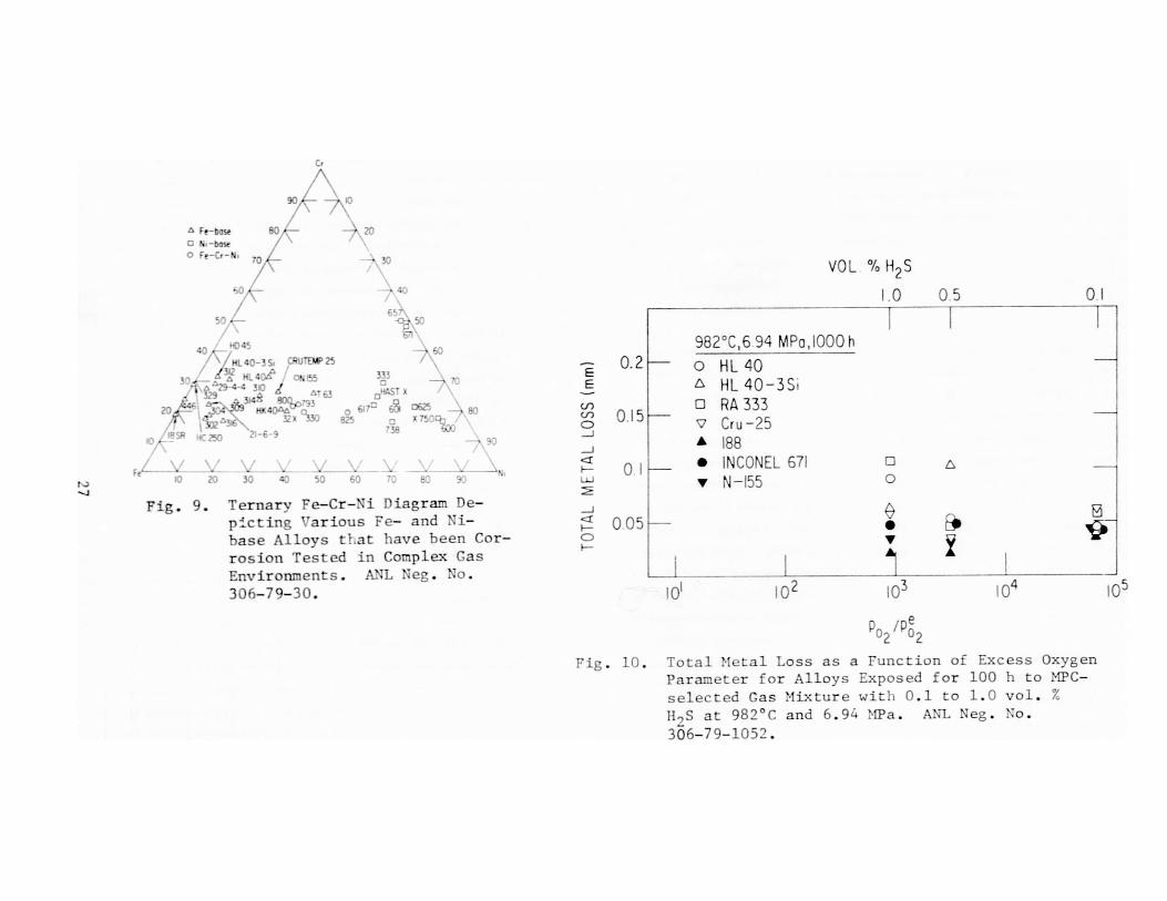
The long-term corrosion behavior of a number of Fe-, Ni-, andCo-base alloys in a mixed-gas environment is being evaluated in the8MetalsProperties Council (MPC) program at I1T ResearcL Institute (IITRI). Figure9 shows the composition:. of the various Fe- and Ni-base alloys that have beenexposed to multicomponent gas mixtures at temperatures up to 982C. Themajority of experiments in this program are conducted at a fixed oxygenpartial pressure while the sulfur in the gas is varied from 0 to 1.0 vol. %11S (see Table VI for the 0, S, and C potentials). In general, weight loss/gain data were obtained for the specimens after exposure to complex gasmixtures; subsequently, the specimens were metallographically examined toevaluate the scale thicknesses and alloy penetration depths in the materials.A summary of experimental conditions used in the IITRI corrosion test programis given in Table V1I. Exposures of 10,000 h duration, at 982 C in the MPC-selected gas mixture containing 0.5 vol. % 11 2S ar.d at 899 C with 1.0 vol. %H2S, have been completed. The experiments at 982 C with 1.0 vol. Z 11 2S andat 899 C with 0.5 vol. % 122S are in progress. Exposures of 1000 h durationhave been completed at 816 C in gas mixtures containing 0.1, 0.5, and 1.0vol. % 112 S. In order to evaluate the effect of a lower p0, than thatestablished by the MPC-selected gas mixture, 1000-h exposures have beenconducted at 982 C with 0.5 vol. % 11 2S and 20 vol. % 1120 (instead of 39.5vol. % 1120). Table VII also lists the values of the excess oxygen partialpressure ratios (p0 9/p,e) established in different experiments. It can beconcluded from the information presented in earlier reports9'10 that excess
P02 ratios in the range used in these experiments (103 to 1() will resultin oxide-mode interact inn for the Fe-, Ni-, and Co-base alloys with highconcentrations of chromium; the effect of long exposure times (up to 10,000 h)will establish the susceptibility of a given alloy to breakaway corrosion.
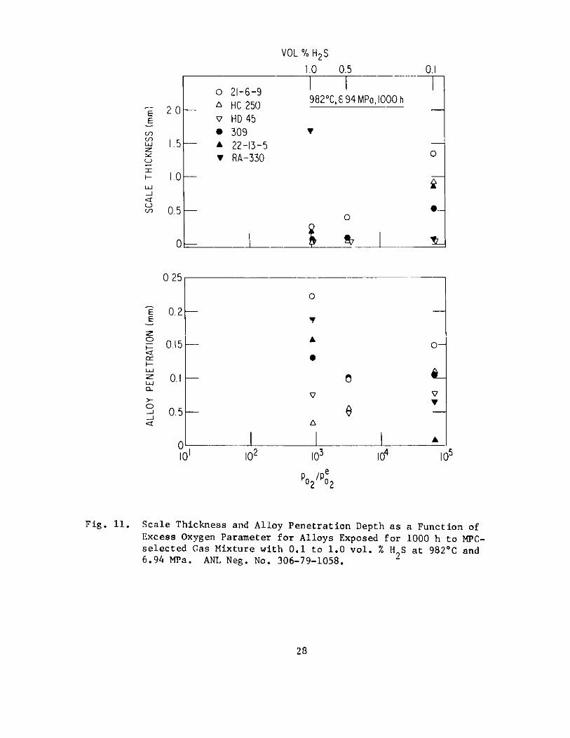
The effect of variation in l2S concentration in the range 0 to1.0 vol. % on the corrosion behavior of a number of commercial materials hasbeen evaluated after 1000-h exposure at 982 C. The results, plotted in Fig.10 as metal loss vs excess oxygen parameter, show an increase in corrosionas the H2S concentration in the gas phase increases. Figure 11 shows thescale thickness and alloy penetration depth as a function of the excessoxygen parameter for a number of alloys that exhibit significant corrosion inH2S-containing atmospheres. The thicknesses of scales developed on these
22
alloys (except RA330 and HD45) are large even with 0.1 vol. % 11 2 S in the gasphase, conditions under which the high-chromium alloys should develop pro-tective oxide layers. It is evident that these alloys show poor oxidationresistance (see data points for 21-6-9, HC-250, 300, etc.), which is im-proved by an increase in the H2S ontent of the gas phase. However, thesealloys will be unsuitable for application in coal-conversion systems becausethey develop thick scales under low-11,S conditions (typical of low-S coalfeedstock) and exhibit sLbstantial intergranular sulfur penetration underhigh-HIS conditions (typical of high-S coal feedstock).
Because complex alloys exposed to multicomponent gas environmentsmay develop a protective oxide scale and at the same time exhibit significantintergranular penetration of sulfur into the substrate material, judicious
selection of an alloy for use in coal-gasification systems requires data onthe extent of sound-metal loss as well as weight change. Such dat a have beenobtained for a number of primary, secondary, and alternate alloys afterexposure to mixed-gas environments at temperatures of 899 and 982*C.8 Theresults show that several commercially available alloys exhibit acceptablecorrosion rates of 0.6 mm y 1 (24 mils y-1), based on 10,000-h exposures;however, it should he noted that these corrosion experiments were conductedat excess oxygen parameter values of t 103 or higher (see Table VIi).
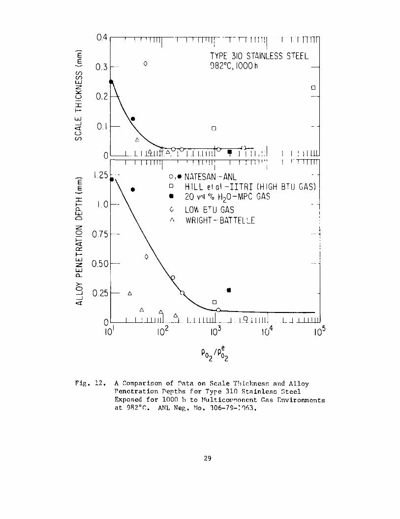
The effect of variation in oxygen and sulfur partial pressures onthe corrosion behavior of alloys can be evaluated by a comparison of 1000-hdata on scale thickness and intergranular penetration obtained by differentresearchers. Natesan 4- 6 ,10-11 obtained data on Incoloy 800 and Type 313stainless steel with varying p0, and pS,) at 9820 and ambient pressure.Wright7 obtained similar data at total j ressures of 34 and 102 atm. Hillet al. 8 obtained data on these alloys for the MPC gas mixture, MPC gasmodified with 20 vol. H20, and low-fItu gas that included nitrogen. Thedata on scale thickness and alloy penetration depth from all these investi-gations are plotted as a function of excess oxygen parameter (p,/p0,e)in Figs. 12 and 13 for Type 310 stainless steel and Incoloy 800,'re-spectively. In general, the results show that below an oxygen pressurethreshold represented by p0 ,,/p0 9 e 103, the total corrosion (scale thickness+ penetration depth) of the all5ys is significant. However, the data ofWright, Hill et al. (low-Btu gas), and Natesan (30 vol. % C 4 in inlet gas)show significantly lower values of scale thickness and penetration depth forTncoloy 800 and probably for Type 310 stainless steel. In these experiments,the oxygen pressure is low enough that a protective oxide layer does notdevelop on the alloy; on the other hand, the carbon activity in the gas ishigh enough to form stable Cr-rich carbides in the alloy. As a result,the corrosion behavior of the material depends or. the relative rates of for-mation of carbides vs sulfides in the scale. Wright has observed a hardlayer of carbide on the specimens tested in these environments. Once thecarbide scale layer is formed, the extent of corrosion will be determined byeither the transport of sulfur through the carbide layer or by the sulfi-dation of carbide particles in the scale layer. Significant carburizationdepths have been reported by Hill et al. for specimens exposed to low-Btu gasenvironments. Very little fundamental information is presently availableon the relative role of carbon and sulfur in the mixed-gas environment onthe corrosion behavior of materials (in the absence of protective oxidescales). Since high carbon activities are expected at elevated system
23

pressures and at low temperatures, it is worthwhile to establish whetherprotective carbide layers rather than fast-growing sulfide scale can bedeveloped on alloy surfaces.
3. Experimental Program
Deposit-induced hot-corrosion behavior of heat-exchanger and gas-turbine materials exposed to multicomponent gas environments is of con-siderable interest in advanced energy systems that utilize fossil fuels.For thi; purpose, the ongoing program includes characterization of environ-ments in low-Btu gasification and direct-combustion processes and theevaluation of materials in complex gas mixtures that simulate normal oper-ating conditions and off-normal excursion situations in these processes.
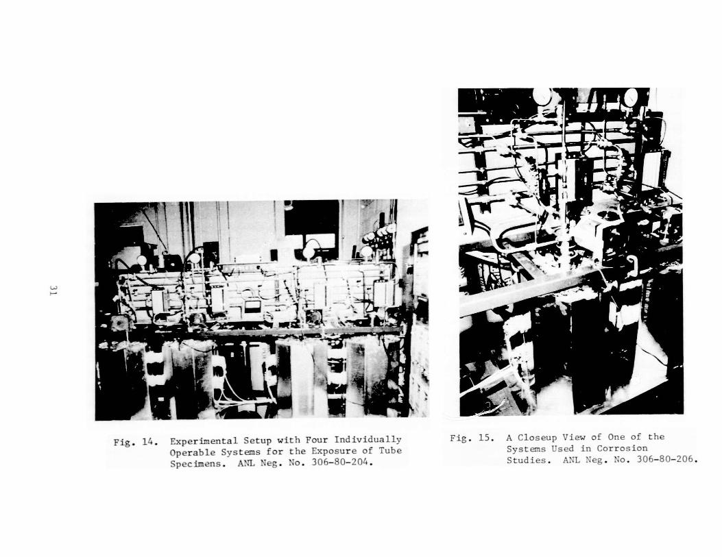
To s imulato the air and stream tubes exposed in an environmentarising from combustion of coal or coal-derived fuels, tube specimens thatare internally cooled with air or inert gas are used in a series of corrosionexperiments. Figure 14 shows the experimental setup, in which four indi-vidually operated systems are used for the exposure of tube specimens.r igurt 15 shows a close-up view of one of the four systems, and Fig. 16shows the details of the corrosion probe. The probe is approximately 40 cmin length, with a specially designed head that incorporates the cooling-fluid path and thermocouples. The temperature in the mixed-gas environmentis measured by a Chromel-Alumel couple inserted in the thermowell. In thefirst few experiments, thermocouples are also spot-welded onto the outer andinner surfaces of tube specimens. Another couple is inserted in the coolingfluid inside the specimen assembly. During a run, the outputs from thesecouples are continuously recorded on a strip chart. Figure 17 shows thedetails of tube specimens in the unassembled and assembled configurationswith the thermocouples in the attached position. At present, experiments arebeing conducted at a metal temperature of 593 C in mixed-gas environmentswith low oxygen partial pressures and as a function of sulfur partial pres-sure.
24
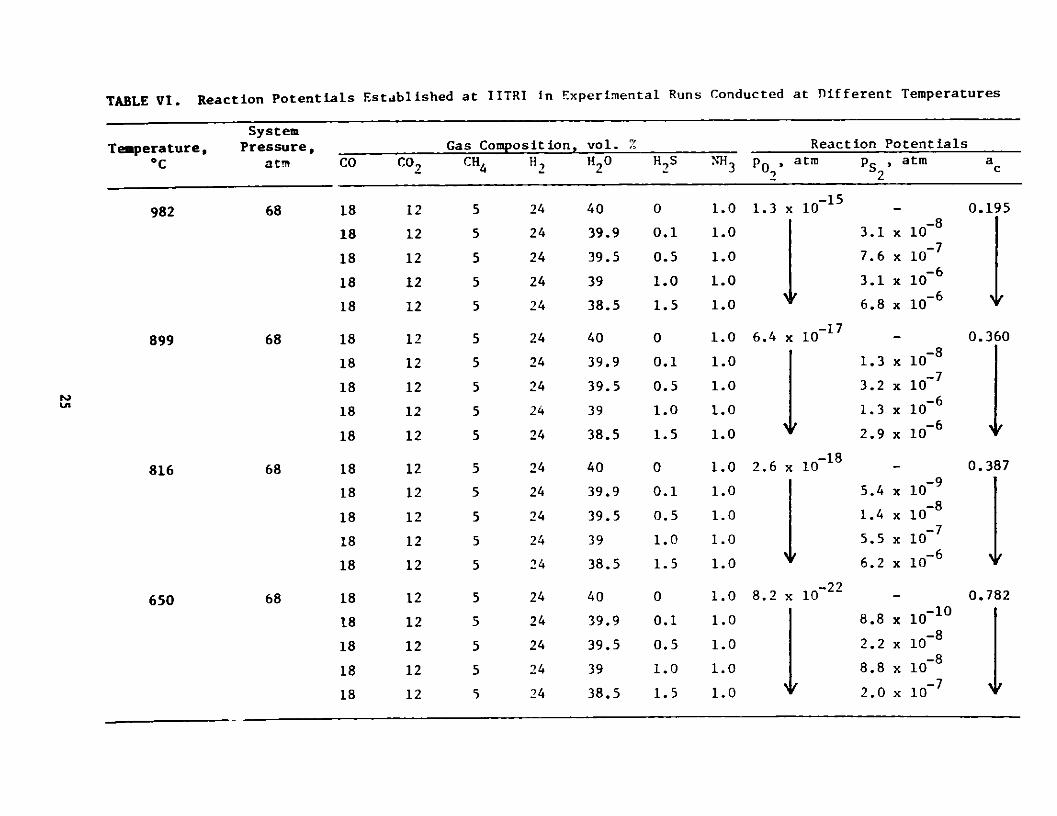
Established at IITRI in Experimental Runs Conducted at Different Temperatures
Temperature,oc
System
Pressure,atm CO CO2,
Gas ComposCH4
it ion, vol. %H' H2O
ReactionPotentials
HIS NH 3 p 0 ,atm pS , atm ac2 2
982
899
68
68
18
18
18
18
18
18
18
18
18
18
18
18
18
18
18
18
18
18
18
18
UN
12
12
12
12
12
12
12
12
12
12
12
12
12
12
12
12
12
12
12
12
5
5
5
5
5
5
5
5
5
5
5
5
5
5
5
5
5
5
5
5
24
24
24
24
24
24
24
24
24
24
24
24
24
24
24
24
24
24
24
24
816
650
40
39.9
39.5
39
38.5
40
39.9
39.5
39
38.5
40
39.9
39.5
39
38.5
40
39.9
39.5
39
38.5
0
0.1
0.5
1.0
1.5
0
0.1
0.5
1.0
1.5
0
0.1
0.5
1.0
1.5
0
0.1
0.5
1.0
1.5
68
68
1.0
1.0
1.0
1.0
1.0
1.0
1.0
1.0
1.0
1.0
1.0
1.0
1.0
1.0
1.0
1.0
1.0
1.0
1.0
1.0
1.3 x 10⁻¹⁵
6.4 x 10~17
2.6 x 10⁻¹⁸
8.2 x 10⁻²
3.1
7.6
3.1
6.8
1.3
3.2
1.3
2.9
5.4
1.4
5.5
6.2
8.8
2.2
8.8
2.0
x 10-8
x10~
x 10- 6
x10-6
- 6
x 10-6
x 106
x 107
x 1086
x 10-10
x10~8
x 10-68
x 1 0-8
x 10- 8
x ic~8
0.195
0.360
0.387
i7
0.782
If
TABLE VI. Reaction Potentials
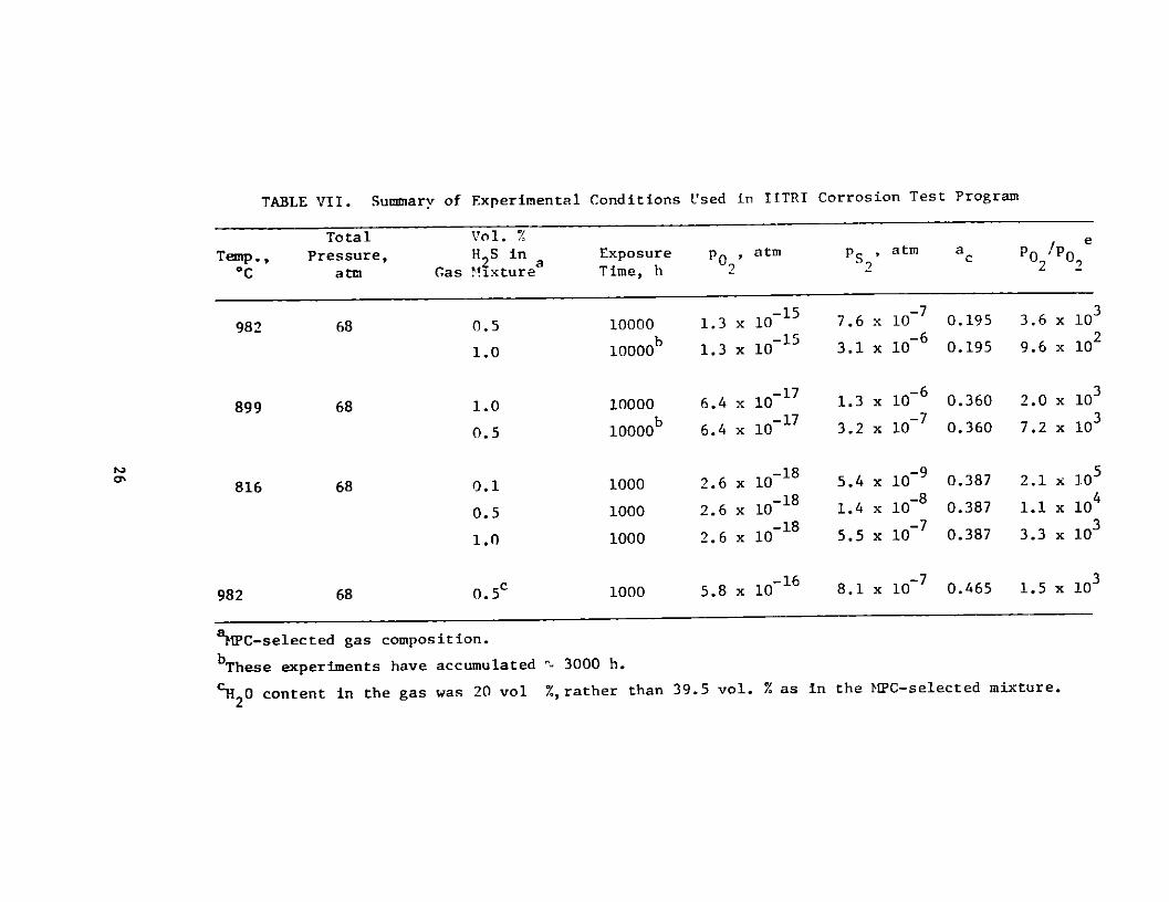
TABLE VII. Summary of Experimental Conditions Used in IITRI Corrosion Test Program
Total Vol. % e
Temp., Pressure, H2S in a Exposure p0 , atm PS , atm ac PO 0,,*C atm Gas Mixture Time, h 2 2 22
982 68 0.5 10000 1.3 x 10¹⁵ 7.6 x 10 0.195 3.6 x 10
b -15 -621.0 10000 1.3 x 10 3.1 x 10 0.195 9.6 x 10²
899 68 1.0 10000 6.4 x 10~17 1.3 x 10⁻⁶ 0.360 2.0 x 10³
b -17 -730.5 10000 6.4 x 10 3.2 x 10 0.360 7.2 x 10³
816 68 0.1 1000 2.6 x 101 8 5.4 x 10⁹ 9 0.387 2.1 x 10⁻¹⁸ -84
0.5 1000 2.6 x 10~ 1.4 x 10 0.387 1.1 x 10
1.0 1000 2.6 x 10⁻¹⁸ 5.5 x 10⁷ 0.387 3.3 x 10³
982 68 0.5c 1000 5.8 x 10⁻¹ 6 8.1 x 10~ 0.465 1.5 x 10³
o'
aNPC-selected gas composition.
bThese experiments have accumulated
H20 content in the gas was 20 vol
' 3000 h.
%, rather than 39.5 vol. % as in the MPC-selected mixture.
90 10
a Fe-base 90 20
C N.-baseo Fe-Cf-N 701
VOL % H 2S
03610 6oi 0625825 o X75r -
738 taj
EE
n
-J
-J
a0
Fig. 9. Ternary Fe-Cr-Ni Diagram De-
picting "arious Fe- and Ni-base Alloys ti.at have been Cor-
rosion Tested in Complex Gas
Environments. ANL Neg. No.
306-79-30.
982 C,6 94 MPoI000 h0.2 0 HL 40
A HL 40-3So RA 333
0.15 - 7 Cru-25A 88
0 I .__ 0 INCONEL 671v N-155
0051
101 102
1.0
G0
44
A
13
05 01
9i- - 04 1
0 10
p0 2 po 2
Fig. ]. Total Metal Loss as a Function of Excess Oxygen
Parameter for Alloys Exposed for 100 h to MPC-selected Gas Mixture witL f.1 to 1.0 vol.
H,S at 982 C and 6.94 MPa. ANL Neg. No.306-79-1052.
r 'K~x330
r,)
EE
Cr)(I)
LU
-J
V-
2.0
1.5
1.0
0.5
0 .
0.25
E
E
F-
a-
0-O
0.2
0.15
0.1
0.5
VOL % H 2S
1.0 0.5 0.1
0
"
V
O-
l -___ 1 _ ___II0n 102
0
8v
105
P /pe02 02
Fig. 11. Scale Thickness and Alloy Penetration Depth as a Function ofExcess Oxygen Parameter for Alloys Exposed for 1000 h to MPC-selected Gas Mixture with 0.1 to 1.0 vol. % H S at 982*C and6.94 MPa. ANL Neg. No. 306-79-1058. 2
28
21-6-9HC 250HD 4530922-13-5
RA-330
982*C, 6.94 MPa, 000 h
"
0
0-0
T
1 l
0
A
V
"
"
"
0.4 T7 T -rTTTT 7 -T 1-1111 FT-IT[
E TYPE 310 STAINLESS STEEL0.3 - 0982*C, 1000 h
z 00.2
S 0.1 0
1.25 0, " NATESAN - ANL
LU HILL et al -IITRI (HIGH BTU GAS)
" 20 vol %/ H20-MPC GAS
a .0 0 WET GAS
o WRIGHT-BATTELLE
2 0.75 -
-
0.25
Q -
0XI ~1 1 I -1111111 ! 1 -14 .1 1.I1II
0S 1.0 102 103 4 105
2 0.
Fig. 12. A Comparison of Data on Scale Thickness and Alloy
Penetration Depths for Tyre 310 Stainless Steel
Exposed for 1000 h to PIulticorpnonent Gas 1 nvironments
at 982*C. ANL Neg. No. 306-79-11%3.
29
0.5
DESTROYED
--
0.1 1-
DL .1
-1 1
1.25
1.0
0.75 -
0.50
0.25 -
10 1
0
~ IJV1 (11T1 1
0.4
0A
LOW-BTU GASWRIGHT -BAT TELLE
0 0
I A U111 fJiLu-L1lil. iJ111 l Ill102 10 3 104 105
p02/p02
Fig. 13. A Comparison of Data on Scale Thicknesses and AlloyPenetration Depths for Incoloy 800 Exposed for 1000 hto ?ulticotnponent Gas Environments at 982 C.ANL Neg. No. 306-79-1070.
30
INCOLOY 8009820C1000 h
--
1 if 1 111 ~~-T TT 1 -
0,0 NATESAN- ANLo HILL elol -IITRI -
(HIGH BTU GAS)" 20 VOL % H 20- MPC GAS
E
(1)
LU
F-
U)
03
0.2
.50
E
0'
F-
w-LU
0
J-J
L_
f
N
rr
Fig. 14. Experimental Setup with Four Individually Fig. 15. A Closeup View of One of the
Operable Systems for the Exposure of Tube Systems Used in Corrosion
Specimens. ANiL Neg. No. 306-80-204. Studies. ANL Neg. No. 306-80-206.

Fig. 1(. Photograph 2hwinig the Dy t a i 1 r a Corrosion Prohe.A :i ': . .. 8 ).2 5
----- a
144
. . Pet*aiis of Ti rbe Spec I'mens in the 1'na ssemhled and Assemb1ed Con-! i gurat ions wit hi lheriup lO" in t e" t t ached Pos it in.A:L Neg. No. 306-80-- 1 .
Task E -- Erosion Behavior of Materials in Coal-conversion Processes(J.Y. Park and W.J. ShJlak)
The objectives of the erosion program at ANL are to develop onengineering data base and the necessary analytical tools for rational designof components subject to erosive wear in coal-conversion plants. Engineeringdesign data will be obtained from erosion tests which will be performed attemperatures and in atmospheres designed to simulate actual plant conditions.The laboratory results will be compared with in-situ measurements currentlybeing obtained from the NDT program at ANL.
Corrosion and erosion cu.-ibration tests on 1015 carbon steel (CS),Type 304 stainless steel (SS), Incoloy 800, and Stellite 6B were performed.Corrosion calibration tests in a simulated gasifier atmosphere (CO 18, CO,12, Cl4 5, H1, 24, H,0 39, N1l 3 1, HS 1 in vol. %) at 816*C were reported pre-
viously.' 3 These'~tests were repeated to ensure reproducibility of theresults. Significant amounts of corrosion were observed in all alloys.Cross sections of the specimens were examined by optical metallography, andmaterial degradation due to corrosion was measured in terms of weight change,loss of substrate thickness, scale formation, and internal corrosion. Theresults of these corrosion calibration tests are similar to those presentedin previous reports.,' 3
A new specimen holder was built to provide more accurate controlof particle impingement angle. Up to forty specimens can he mounted for asingle test. A room-temperature erosion calibration test was performed on1015 CS, Type 304 SS, Incoloy 800, RA310 SS and Stellite 6B specimens usingthe new specimen holder and 100-grit size (150-um) alumina at an impingementvelocity of 22 m/s and angles 6-36'. Erosion rate (mass loss/mass impacted)was calculated from weight loss, and the results are shown in Table VIII.The rate is in the range of 0.03-0.09 mg/g, which is about 7 times lowerthan that obtained in earlier tests at 70 m/s using 240-grit size (50-11m)luminaa 6 However, the variation is consistent with the expected dependenceof erosion rate on velocity.
During the next quarter, a few additional erosion calibrationtests 'ill be completed at higher impingement angles, and erosion-corrosioncalibration tests will be performed in the simulated gasifier atmosphereat 816 C. An external feed reservoir with a level indicator will be in-stalled in order to perform continuous long-term erosion-corrosion tests.(The current internal feed reservoir capacity, 25 kg of alumina, limitstests to t 50 h unless very low particle fluxes are used.)
33
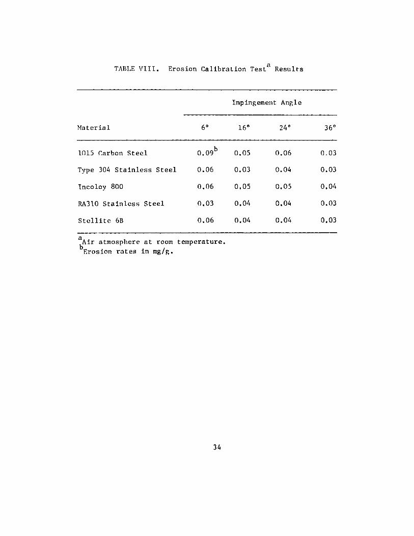
TABLE VIII. Erosion Calibration Testa Results
Impingement Angle
Material 60 160 240 360
1015 Carbon Steel 0 .09b 0.05 0.06 0.03
Type 304 Stainless Steel 0.06 0.03 0.04 0.03
Incoloy 800 0.06 0.05 0.05 0.04
RA310 Stainless Steel 0.03 0.04 0.04 0.03
Stellite 6B 0.06 0.04 0.04 0.03
aAir atmosphere at room temperature.
bErosion rates in mg/g.
34
Task F -- Failure Analysis (P.R. )eioks, 5. 7reenbcrg, T. Y.N. Wan,g.Ml. Drago.7. and J. E. 1ia t tery )
1. Experimental Thermowells for ICT Ash Agglomerating Gasifier
Seven experimental thermowells have been prepared for trialexposure in the IGT Ash Agglomerating Casifier (U-Gas) Pilot Plant. Thebottom portions of these thermowells, which will see the most severe con-
ditions in service, were fabricated using several combinations of alloys
and coatings as summarized in Table IX. The Cr-Si and Cr-Al-Hf coatingswere applied by the Lockheed Research Laboratories of Palo Alto, CA usinga slurry fusion process, and the aluminized coatings were applied by
Alon Processing, Inc. of Tarentum, PA. In all cases, the upper portions
of the thermowells were fabricated of uncoated Type 304 stainless steel with
carbon steel mounting flanges.
After leak testing and radiographic inspection of the welds, thecompleted thermowells were delivered to personnel at the U-Gas Pilot Plantin February. The principal objective in testing the trial alloys and coatingsis to determine their resistance to high-temperature sulfidation, with less
emphasis on their resistance to erosion by particles in the gasifier luidizedbed. Accordingly, the test plan calls for exposing the thermowells atlocations somewhat above the operating height of the bed, but still in thehigh-temperature portion of the gasifier. Only three locations satisfyingthese requirements are available, and thermow.'ls 2 through 7 will be ex-posed in these locations in two series of runs. Thermowell 1, which is
identical with thermowell 2, will he tested at a different location in the
gasifier near the top of the fluidized bed under conditions of combinederosive wear and sulfidation.
At present, experimental thermowells 2, 3, and 7 have been in-stalled at positions approximately 1.1, 1.4, and 2.3 m (3.5, 4.5, and 7.5 ft)above the normal operating height of the bed, and thermowell 1 has beeninstalled approximately 0.4 m (1.4 ft) above the top of the bed. However,the plant has not been operated subsequent to the installation of thethermowells, and the schedule for the resumption of operations is uncertainat this time.
2. Tubing and Compressor Diaphragm Assembly Samples from Grand ForksEnergy Technolog'fCenter
An examination of tubing bend and compressor diaphragm samplesfrom the Grand Forks Energy Technology Center coal-liquefaction continuous-process unit has been completed. The tubing samples consist of two Type 316stainless steel bends (14.3 mm OD) from a line connecting the autoclavereactor to the high-temperature slurry-gas separator. The compressor dia-phragm set consists of an inner and outer ply made of Type 316 stainlesssteel and a center ply made of Type 301 stainless steel. A more completedescription of these components and their operating environments is pro-vided in a previous report.
35
The results of this examination may be summarized as follows:
1. A thorough examination of the ID of the tubing bendsindicates that no cracking is 'sent.
2. Through-wall cracks have been acted in both thediaphragm in contact with the ga and the diaphragm incontact with hydraulic fluid. No cracking was observedin the center diaphragm.
3. The cracking in the compressor diaphragm in contact withthe gas apparently initiated on the gas side. In thecase of the diaphragm in contact with the hydraulicfluid, cracking initiated on the fluid side in an areaof localized pitting.
3. Solids Transfer Line from ICT IYGAS Pilot Plant
Portions of a corroded and perforated solids transfer line fromthe IT IIYCAS coal gasification pilot plant have been sent to Argonne foranalysis. The failed line runs vertically approximately down the center ofthe gas if ier reactor vessel, and is used to transport char particles atlow velocities (< 1 m/s) from the second (high-temperature reactor) stageof the vessel to the third (steam-oxygen gasifier) stage. The line is madeof 7.6-cm (3-in.)-ID Schedule 80 pipe welded together at several points alongits length using 7.6-cm (3-in.)-long, 9.5-cm (3.75-in.)-ID Schedule 120sleeve couplings. The ends of the couplings are slipped over the ends ofthe pine sections to he joined and circumferentially welded to them. Thepiping material and weld couplings are specified to be RA 330, and the weldfiller metal used to join the pipe to the couplings is Inconel 182. Thetotal length of the transfer line is about 8.2 m (26.8 ft), and it is ter-minated by a hot-char valve at the outlet end in the steam-oxygen gasifierzone. The line is supported inside the reactor vessel by means of a flatplate welded to the pipe about two-thirds of the way up its length. Thisflat plate rests on a refractory grid support structure between the secondand third stages of the vessel. A pair of bolted flanges are used to providea mechanical joint in the line immediately above the grid support plate.
The operating conditions of the HYGAS pilot plant over the lastseveral years since the present line was installed have been somewhat vari--able, largely because of the variety of feedstocks employed. However, arepresentative average gas composition from the steam-oxygen gasifier stage,after equilibration at room temperature, is given by the analysis (in molepercent) 56.9 1120, 16.9 H2, 16.2 C02 , 8.0 :o, 1.9 C1 4, and 0.1 H2S. Theoperating temperature along the length of the transfer line varies from about870-980 C (1600 to 1800 F) in the steam-oxygen gasifier zone to about 540-82 0 C (1000 to 1500 F) in the high-temperature reactor zone.
A visual examination of the failed components revealed that, in allcases, failure had occurred at welds. Three of the failures were located atweld couplings, one at a welded junction with a smaller-diameter line, andone each at the welds connecting the support plate and coupling flange to theline. Tn all cases, failure was due to corrosive attack of the weld metal
36
and adjacent base metal from the OD. Complete perforation occurred at aminimum of three locations.
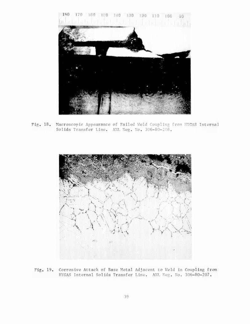
Figure 18 shows the macroscopic appearance of a failed weldedcoupling after initial axial sectioning. Attack on the weld filler metaland adjacent base metal at both ends of the coupling is apparent, with com-plete penetration of the pipe wall visible on the right-hand side of thefigure. The general features observed in the macroscopic c.:amination of theremaining failure locations were rather similar. Failure invariably occurredby attack of the weld filler metal from the OD, generally followed by spreadof the corrosive attack into the adjacent base metal. Less severe weld-metalattack was noted in the portion of the line located in the high-temperaturereactor zone, where the operating temperatures tended to be somewhat lower.No significant base-metal attack was observed in any of the samples examinedexcept as an immediate consequence of adjacent weld-metal attack.
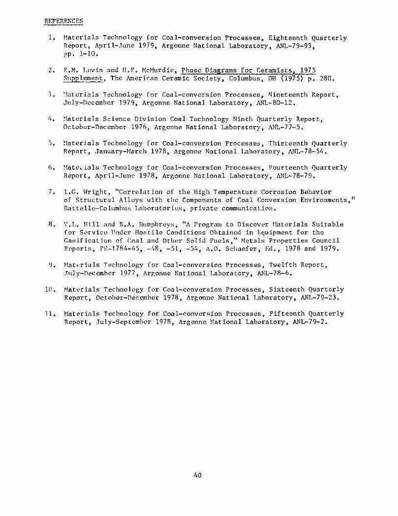
Metallographic examination of sections taken from the failed com-ponents typically reveals considerable surface and internal oxidation andsulfidation below the outer corrosio.i-product layer. Figure 19 shows theintergranular and twin-boundary attack observed in the base metal adjacentto an attacked weld-metal region. X-ray analysis identifies both chromiumoxide and sulfide phases in the grain and twin boundaries, with the probableprecipitation of the M 2 3 C 6 carbide inside the grains. The corrosion-productscale is found to consist of chromium and iron oxides as well as significantamounts of nickel sulfide.
The present failure is tentatively attributed to severe sulfidationof the high-nickel (o 67 wt. %) Inconel 182 weld filler metal in the HYGASoperating environment. Both the x-ray analyses and the morphology of thesurface scale indicate that the low melting point Ni-Ni3S, eutectic wasformed as one of the corrosion products at the surface of the weld metal..Since the operating temperature of the transfer line was generally well inexcess of the 635 C (1175*F) melting point of this eutectic, the surfacecorrosion product was at least partly liquid during operation. This liquidphase would tend to inhibit the formation of a protective Cr203 layer on thecontacting metal surface as well as to flux away any oxide already present.The weld metal and adjacent base metal would thus he susceptible to furthersulfidation as well as internal oxidation, as seen in Fig. 19. Alternativelower-nickel weld filler metals appropriate for the present application arecurrently being explored.
4. Thermocouple from ICT HYGAS Pilot Plant
A failure analysis has been initiated on samples from a thermo-couple taken from the IGT HYGAS coal gasification pilot plant. The failedthermocouple is a Type K (chromel/alumel) device with a Type 310 stainlesssteel sheath and MgO insulation. The sheath ruptured after approximately361 hours of service in the steam-oxygen gasifier zone of the HYGAS reactorat temperatures ranging from 871 to 982 C (1600 to 1800 F) and pressuresof from 3.5 to 4.5 Mpa (500 to 650 psi). The thermocouple was not protectedby a thermowell. Initial x-ray diffraction results indicate that the con-version of the MgO insulation to Mg(OH), in the failed regions, and the
37
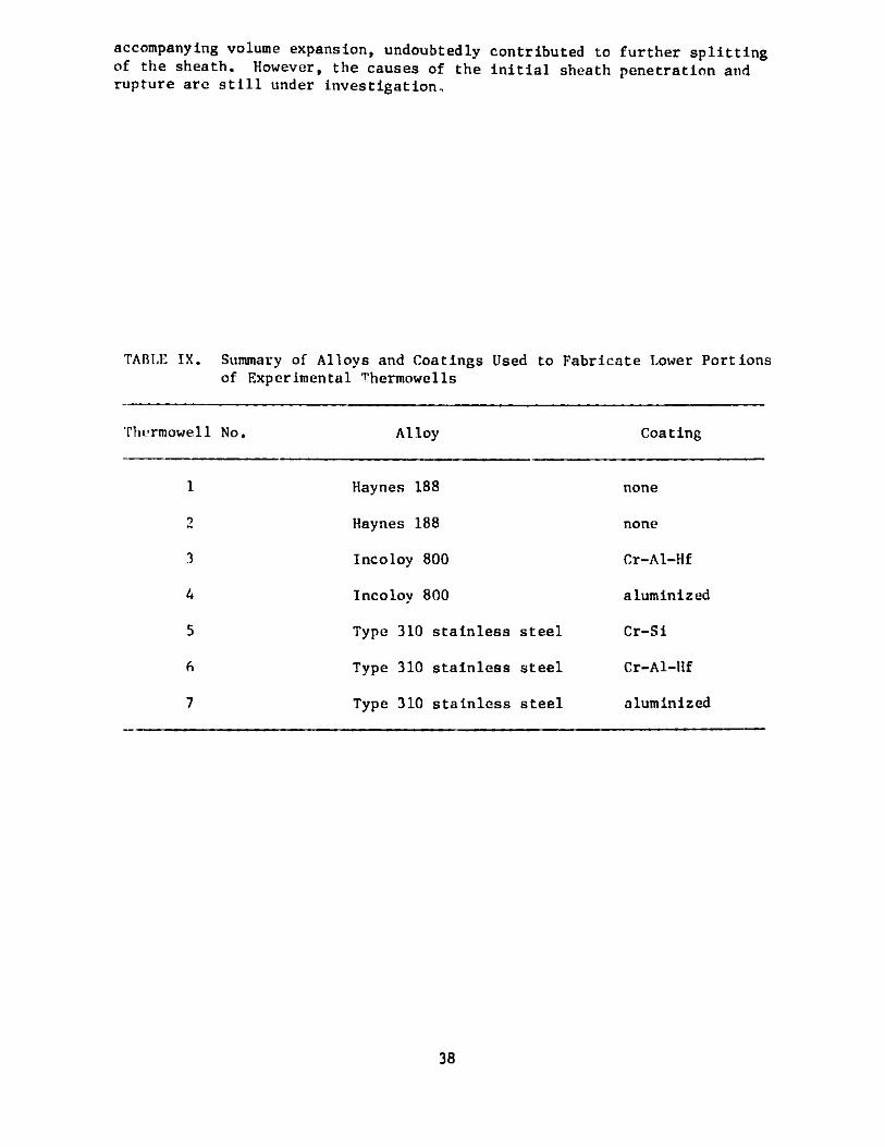
accompanying volume expansion, undoubtedly contributed to further splittingof the sheath. However, the causes of the initial sheath penetration andrupture are still under investigation,
TABLE IX. Summary of Alloys and Coatings Used to Fabricate Lower Portionsof Experimental Thermowells
Thermowell No. Alloy Coating
1 Haynes 188 none
2 Haynes 188 none
3 Incoloy 800 Cr-Al-Hf
4 Incoloy 800 aluminized
5 Type 310 stainless steel Cr-Si
6 Type 310 stainless steel Cr-Al-Hf
7 Type 310 stainless steel aluminized
38
I9 , -'odi..U : % 3u 2u \) O();G4j C
I
1 i . 18. Macroscop ic Appoaranc e c F a it ( 'c ! - \S InternalSolids Transfer Line. A:1 L eg.
B '. N '
" ir ' ' S.:'. -, ' '' ," ' r~1~~ ~ ~ ~ , I .i .' jY ,
.9
, 0
A &
r 1'' r-
a-
l
t
Iig. 1 . C* ArroSi At ;I k l BaS;l i l di
1!YGA\8 Internal Se I iJl; TIransfer
(:\ at ' II in Coup] in)', from
(I
/f
f'
-~ N09. - 9
/9
I 7' ,. 'a 9
.4
* . >~( K,
6-60-
. 1
1.
L int,. A'I ', . 06-80-:)07.
REFERENCES
1. Materials Technology for Coal-conversion Processes, Eighteenth QuarterlyReport, April-June 1979, Argonne National Laboratory, ANL-79-93,pp. 1-10.
2. E.M. Levin and H.F. McMurdie, Phase Diagrams for Ceramists, 1975Stipplement,The American Ceramic Society, Columbus, OH (1975) p. 280.
3. Materials Technology for Coal-conversion Processes, Nineteenth Report,July-December 1979, Argonne National Laboratory, ANL-80-12.
4. Materials Science Division Coal Technology Ninth Quarterly Report,October-December 1976, Argonne National Laboratory, ANL-77-5.
5. Materials Technology for Coal-conversion Processes, Thirteenth QuarterlyReport, January-March 1978, Argonne National Laboratory, ANL-78-54.
6. Matey ials Technology for Coal-conversion Processes, Fourteenth QuarterlyReport, April-June 1978, Argonne National Laboratory, ANL-78-79.
7. I.G. Wright, "Correlation of the High Temperature Corrosion Behaviorof Structural Alloys with the Components of Coal Conversion Environments,"Battelle-Columbus Laboratories, private communication.
8. V.L. 11ll and B.A. Humphreys, "A Program to Discover Materials Suitablefor Service Under Hostile Conditions Obtained in Equipment for theGasification of Coal and Other Solid Fuels," Metals Properties CouncilReports, FE-1784-45, -48, -51, -54, A.O. Schaefer, Ed., 1978 and 1979.
9. Materials Technology for Coal-conversion Processes, Twelfth Report,July-December 1977, Argonne National Laboratory, ANL-78-6.
10. Materials Technology for Coal-conversion Processes, Sixteenth QuarterlyReport, October-December 1978, Argonne National Laboratory, ANL-79-23.
11. Materials Technology for Coal-conversion Processes, Fifteenth QuarterlyReport, July-September 1978, Argonne National Laboratory, ANL-79-2.
40