mathworks technology session at ge closed-loop motor
TRANSCRIPT
1 © 2012 The MathWorks, Inc.
MathWorks Technology Session at GE
Closed-Loop Motor Control
Development
February 28, 2013
Brad Hieb
Tom Priestley
Marc Semma

2
Design Controller
Control System Toolbox
Robust Control Toolbox
Model Predictive Control Tbx
Optimize Control System
Simulink Control Design
Simulink Design Optimization
Model Physical Plant
System Identification Toolbox
Model-Based Calibration Tbx
Simscape
data model

3
Embedded System
Motor
Hardware
Controller
C Code
System Model
Model Based Design for Embedded Controls
Controller
C Code
Controller
Model
Motor
Model
Motor
Hardware

4
Embedded System
Motor
Hardware
Controller
C Code
System Model
System Modeling and Simulation
GE Tech
Session, Tues.
March 26
Controller
C Code
Controller
Model
Motor
Model
Motor
Hardware

5
What’s Next
Introduction and overview
PMSM motor characterization Characterization tests
Test data to model parameters
Validating the characterized model
Control system design Control model architecture
Tuning control parameters
Verifying closed-loop performance
Q&A
6 © 2012 The MathWorks, Inc.
Characterizing a Permanent Magnet
Synchronous Machine
Brad Hieb – Application Engineer
7
Motivation
Why characterize the motor?
– To develop a plant model
Why develop a plant model?
– To simulate the system
Why simulate the system?
– Simulation is a safe environment to try out new ideas without
the risk of damaging prototype hardware.
– Visualization and analysis of the complex data in our system.
– Gain confidence in our controller design before deploying on
hardware.
8
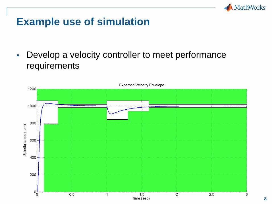
Example use of simulation
Develop a velocity controller to meet performance
requirements

9
But Does it Work on Hardware?

10
Key Point
Create accurate plant models by executing tests,
identify parameter values and verifying against real-
world data
Test Identify
Parameters Verify

11
What do These Particular Models Look Like?

12
Surface Mount PMSM Equations
Mechanical Model
Electrical Model
𝑣𝑑 = 𝑅𝑖𝑑 − 𝐿𝑞𝑝𝜔𝑟 𝑖𝑞 + 𝐿𝑑
𝑑
𝑑𝑡𝑖𝑑
𝑣𝑞 = 𝑅𝑖𝑞 + 𝑝𝜔𝑟 𝐿𝑑 𝑖𝑑 + 𝜆 + 𝐿𝑞
𝑑
𝑑𝑡𝑖𝑞
𝜔𝑒 = 𝑝𝜔𝑟
𝑇𝑒 = 1.5𝑝 𝜆𝑖𝑞 + 𝐿𝑑 − 𝐿𝑞 𝑖𝑑 𝑖𝑞
𝑇𝑒 = 𝐾𝑡𝑖𝑞 𝑎𝑠𝑠𝑢𝑚𝑒𝑠 𝑟𝑜𝑢𝑛𝑑 𝑟𝑜𝑡𝑜𝑟, 𝐿𝑑 = 𝐿𝑞
𝑑
𝑑𝑡𝜔𝑟 =
1
𝐻 𝑇𝑒 − 𝑠𝑔𝑛 𝜔𝑟 𝐽0 − 𝑏𝜔𝑟 − 𝑇𝑙𝑜𝑎𝑑

13
Required Parameters
Electrical Model
Mechanical Model
𝑣𝑑 = 𝑅𝑖𝑑 − 𝐿𝑞𝑝𝜔𝑟 𝑖𝑞 + 𝐿𝑑
𝑑
𝑑𝑡𝑖𝑑
𝑣𝑞 = 𝑅𝑖𝑞 + 𝑝𝜔𝑟 𝐿𝑑 𝑖𝑑 + 𝜆 + 𝐿𝑞
𝑑
𝑑𝑡𝑖𝑞
𝜔𝑒 = 𝑝𝜔𝑟
𝑇𝑒 = 1.5𝑝 𝜆𝑖𝑞 + 𝐿𝑑 − 𝐿𝑞 𝑖𝑑 𝑖𝑞
𝑇𝑒 = 𝐾𝑡𝑖𝑞 𝑎𝑠𝑠𝑢𝑚𝑒𝑠 𝑟𝑜𝑢𝑛𝑑 𝑟𝑜𝑡𝑜𝑟, 𝐿𝑑 = 𝐿𝑞
𝑑
𝑑𝑡𝜔𝑟 =
1
𝐻 𝑇𝑒 − 𝑠𝑔𝑛 𝜔𝑟 𝐽0 − 𝑏𝜔𝑟 − 𝑇𝑙𝑜𝑎𝑑
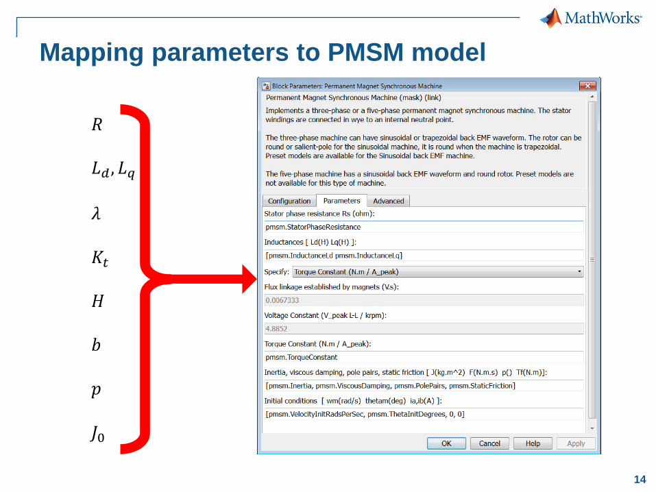
14
Mapping parameters to PMSM model
𝑅
𝐿𝑑 , 𝐿𝑞
𝜆
𝐾𝑡
𝐻
𝑏
𝑝
𝐽0
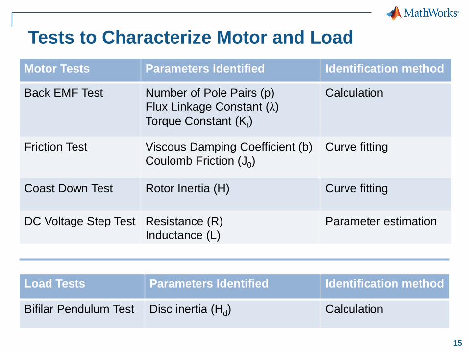
15
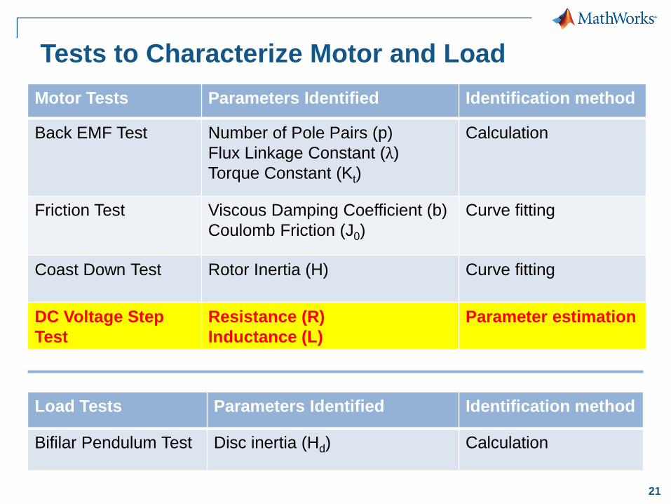
Tests to Characterize Motor and Load
Motor Tests Parameters Identified Identification method
Back EMF Test
Number of Pole Pairs (p)
Flux Linkage Constant (λ)
Torque Constant (Kt)
Calculation
Friction Test
Viscous Damping Coefficient (b)
Coulomb Friction (J0)
Curve fitting
Coast Down Test
Rotor Inertia (H) Curve fitting
DC Voltage Step Test Resistance (R)
Inductance (L)
Parameter estimation
Load Tests Parameters Identified Identification method
Bifilar Pendulum Test Disc inertia (Hd) Calculation
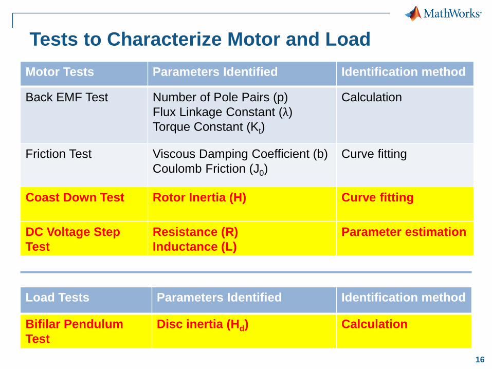
16
Tests to Characterize Motor and Load
Motor Tests Parameters Identified Identification method
Back EMF Test
Number of Pole Pairs (p)
Flux Linkage Constant (λ)
Torque Constant (Kt)
Calculation
Friction Test
Viscous Damping Coefficient (b)
Coulomb Friction (J0)
Curve fitting
Coast Down Test
Rotor Inertia (H) Curve fitting
DC Voltage Step
Test
Resistance (R)
Inductance (L)
Parameter estimation
Load Tests Parameters Identified Identification method
Bifilar Pendulum
Test
Disc inertia (Hd) Calculation

17
Tests to Characterize Motor and Load
Motor Tests Parameters Identified Identification method
Back EMF Test
Number of Pole Pairs (p)
Flux Linkage Constant (λ)
Torque Constant (Kt)
Calculation
Friction Test
Viscous Damping Coefficient (b)
Coulomb Friction (J0)
Curve fitting
Coast Down Test
Rotor Inertia (H) Curve fitting
DC Voltage Step Test Resistance (R)
Inductance (L)
Parameter estimation
Load Tests Parameters Identified Identification method
Bifilar Pendulum Test Disc inertia (Hd) Calculation

18
Coast Down Test
Coast down test used to identify:
Rotor inertia (H)
Test Extract
Parameters Verify
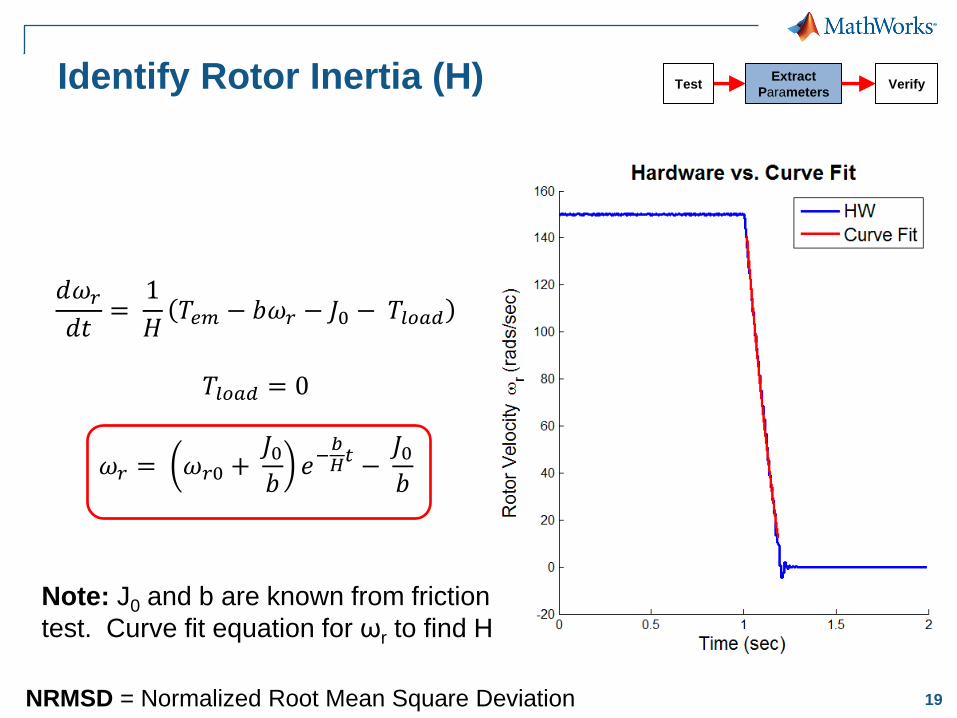
19
Identify Rotor Inertia (H)
𝑑𝜔𝑟
𝑑𝑡=
1
𝐻𝑇𝑒𝑚 − 𝑏𝜔𝑟 − 𝐽0 − 𝑇𝑙𝑜𝑎𝑑
𝑇𝑙𝑜𝑎𝑑 = 0
𝜔𝑟 = 𝜔𝑟0 + 𝐽0𝑏
𝑒−𝑏𝐻𝑡 −
𝐽0𝑏
NRMSD = Normalized Root Mean Square Deviation
Note: J0 and b are known from friction
test. Curve fit equation for ωr to find H.
Test Extract
Parameters Verify

20
Validate Coast Down Test
NRMSD = Normalized Root Mean Square Deviation
Test Extract
Parameters Verify
21
Tests to Characterize Motor and Load
Motor Tests Parameters Identified Identification method
Back EMF Test
Number of Pole Pairs (p)
Flux Linkage Constant (λ)
Torque Constant (Kt)
Calculation
Friction Test
Viscous Damping Coefficient (b)
Coulomb Friction (J0)
Curve fitting
Coast Down Test
Rotor Inertia (H) Curve fitting
DC Voltage Step
Test
Resistance (R)
Inductance (L)
Parameter estimation
Load Tests Parameters Identified Identification method
Bifilar Pendulum Test Disc inertia (Hd) Calculation

22
DC Voltage Step Test
Used to identify:
Phase resistance (R)
Phase inductance (L)
Test Extract
Parameters Verify
23
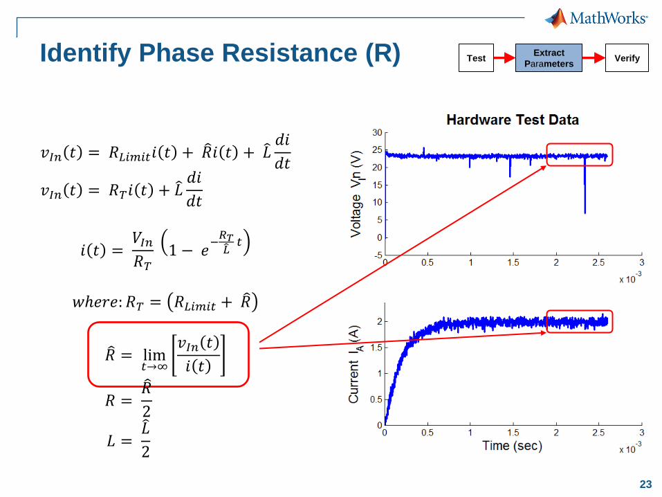
Identify Phase Resistance (R)
𝑣𝐼𝑛 𝑡 = 𝑅𝐿𝑖𝑚𝑖𝑡𝑖 𝑡 + 𝑅 𝑖 𝑡 + 𝐿 𝑑𝑖
𝑑𝑡
𝑣𝐼𝑛 𝑡 = 𝑅𝑇𝑖 𝑡 + 𝐿 𝑑𝑖
𝑑𝑡
𝑖 𝑡 = 𝑉𝐼𝑛
𝑅𝑇 1 − 𝑒
−𝑅𝑇𝐿
𝑡
𝑤𝑒𝑟𝑒: 𝑅𝑇 = 𝑅𝐿𝑖𝑚𝑖𝑡 + 𝑅
𝑅 = lim𝑡→∞
𝑣𝐼𝑛 𝑡
𝑖 𝑡
𝑅 = 𝑅
2
𝐿 = 𝐿
2
Test Extract
Parameters Verify
24
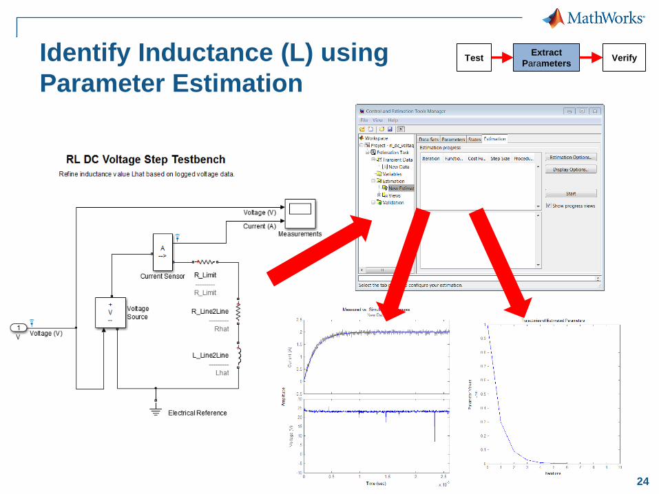
Identify Inductance (L) using
Parameter Estimation
Test Extract
Parameters Verify

25
Validate DC Voltage Step Test
NRMSD = Normalized Root Mean Square Deviation
Test Extract
Parameters Verify

26
Tests to Characterize Motor and Load
Motor Tests Parameters Identified Identification method
Back EMF Test
Number of Pole Pairs (p)
Flux Linkage Constant (λ)
Torque Constant (Kt)
Calculation
Friction Test
Viscous Damping Coefficient (b)
Coulomb Friction (J0)
Curve fitting
Coast Down Test
Rotor Inertia (H) Curve fitting
DC Voltage Step Test Resistance (R)
Inductance (L)
Parameter estimation
Load Tests Parameters Identified Identification method
Bifilar Pendulum
Test
Disc inertia (Hd) Calculation

27
Bifilar Pendulum Test
Bifilar pendulum test used to
identify:
Disc inertia (Hd)
Test Extract
Parameters Verify

28
Identify Disc Inertia (Hd)
𝐻𝑑 = 𝑚𝑑𝑔 𝑇2𝑏2
4𝜋2𝐿
𝑤𝑒𝑟𝑒: 𝑚𝑑 = 𝑚𝑎𝑠𝑠 𝑜𝑓 𝑑𝑖𝑠𝑐 𝑔 = 𝑎𝑐𝑐𝑒𝑙𝑒𝑟𝑎𝑡𝑖𝑜𝑛 𝑜𝑓 𝑔𝑟𝑎𝑣𝑖𝑡𝑦 𝑇 = 𝑝𝑒𝑟𝑖𝑜𝑑 𝑜𝑓 𝑑𝑖𝑠𝑐 𝑟𝑜𝑡𝑎𝑡𝑖𝑜𝑛
Measurements:
L = 2.356 (m)
b = 0.0565 (m)
md = 0.0425 (kg)
T = 2.21 (sec)
Test results
Hd = 6.993e-5 (kg-m2)
Test Extract
Parameters Verify

30
Validate Bifilar Pendulum Test
Simulation result
T = 2.21 (sec)
Parameters:
L = 2.356 (m)
b = 0.0565 (m)
md = 0.0425 (kg)
Hd = 6.993e-5 (kg-m2)
Test result
T = 2.21 (sec)
Test Extract
Parameters Verify

31
Key Point
Create accurate plant models by executing tests,
identify parameter values and verifying against real-
world data
Test Identify
Parameters Verify

32
Putting the pieces together
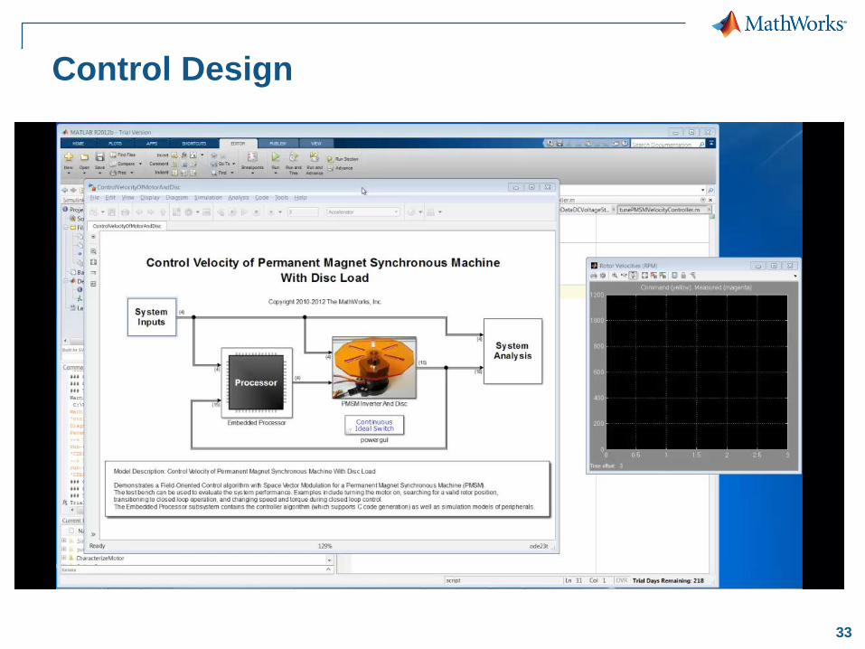
33
Control Design

34
Compare Closed Loop Simulation with
Hardware

35
Where can I find more information?
Explore a demo on generating C code from a controller and verifying its compiled behavior and execution time
>> docsearch "Field-Oriented Control of Permanent Magnet
Synchronous Machine"
http://mathworks.com/products/demos/shipping/rtw/rtwdemo_pmsmfoc_script.html
Watch a recorded webinar: “Embedded Code Generation for AC Motors” http://www.mathworks.com/company/events/webinars/wbnr61549.html
Watch 2012 MathWorks Automotive Conference recording of: “Parameterizing and Verifying a Permanent Magnet Synchronous Motor Model” http://www.mathworks.com/company/events/conferences/automotive-conference-michigan/2012/proceedings/registration.html?video=3
Enroll in SAE Course: “Model Based Design: Delivering Quality Electronic Products Faster” http://www.sae.org/pdevent/C0806

36
Questions

37
End

38
Backup Slides

41
Tests to Characterize Motor and Load
Motor Tests Parameters Identified
Back EMF Test
Number of Poles (P)
Flux Linkage Constant (Λ𝑝𝑚)
Torque Constant (Kt)
Friction Test
Viscous Damping Coefficient (b)
Coulomb Friction (J0)
Coast Down Test
Rotor Inertia (H)
DC Voltage Step Test Resistance (R)
Inductance (L)
Load Tests Parameters Identified
Bifilar Pendulum Test Disc inertia (Hd)

42
Tests to Characterize Motor and Load
Motor Tests Parameters Identified
Back EMF Test
Number of Poles (P)
Flux Linkage Constant (Λ𝑝𝑚)
Torque Constant (Kt)
Friction Test
Viscous Damping Coefficient (b)
Coulomb Friction (J0)
Coast Down Test
Rotor Inertia (H)
DC Voltage Step Test Resistance (R)
Inductance (L)
Load Tests Parameters Identified
Bifilar Pendulum Test Disc inertia (Hd)

43
Tests to Characterize Motor and Load
Motor Tests Parameters Identified
Back EMF Test
Number of Poles (P)
Flux Linkage Constant (Λ𝑝𝑚)
Torque Constant (Kt)
Friction Test
Viscous Damping Coefficient (b)
Coulomb Friction (J0)
Coast Down Test
Rotor Inertia (H)
DC Voltage Step Test Resistance (R)
Inductance (L)
Load Tests Parameters Identified
Bifilar Pendulum Test Disc inertia (Hd)