matlab for signal processing - secs.oakland.eduganesan/old/courses/cse671su08/matlab f… · matlab...
TRANSCRIPT

©20
05 T
he M
athW
orks
, Inc
.
MATLAB for signal processing
Houman Zarrinkoub, PhD.Product ManagerSignal Processing Toolboxes
2
Outline
IntroductionFilter Design, simulation and implementationAdaptive and Multirate filtersSpectral analysis of signalsFixed-point representation of signals and filtersPath to C and HDL implementationAlgorithm verification & validationSummaryQ & A

3
Ubiquitous signal processing across industries
Aerospace and DefenseAutomotiveCommunicationsElectronics and SemiconductorComputers and Office EquipmentEducation

4
MATLAB as the platform for Signal Processing & Technical Computing
Data
Software
Hardware
Analysis and ModelingVisualizationAlgorithm DevelopmentPrototyping & SimulationApplication DeploymentVerification & Validation
Reporting and Documentation
Application Deployment

5
MATLAB for algorithm developmentSimulink for System & Product development
RTW
Embedded Targets
Link products
Verification,HIL Test
CodeGeneration
SystemModeling,
Simulation &Partitioning
SystemComponents
EnvironmentEffects
EmbeddedAlgorithmsAlgorithm
Design &Analysis
EmbeddedSoftware
EmbeddedHardware
System Design TestResearch
DataAnalysis &
VisualizationData Acq & Import
MathematicalModeling
SP, Comms,Video & Image
Blocksets
SimulinkMATLAB
Signal Processing,
Fixed Point,Filter Design
Toolboxes
RapidPrototyping Im
plementRequirements
Specifications

6
MATLAB Tools for Signal Processing• Analysis of signals and design of filters
• Signal Processing toolbox• Filter Design toolbox
• Fixed-Point representation of signals• Fixed-Point toolbox
Related productsWavelet, Statistics, Image Processing toolboxes
System-level designSimulink and Signal Processing Blockset
Path to HDL implementationFilter Design HDL Coder
Hardware and software verificationLink products (CCS and ModelSim)
7
Filter design, simulation & implementation
Signal Processing & Filter Design toolboxes Single-rate filters
Lowpass, highpass, bandpass, etc. Designed based on spectral specificationsEmployed across many applications (i.e., modeling linear time-invariant systems)
Adaptive filtersModeling linear time-varying systemsLearn and adapt to changes of the desired signalImportant applications in noise and echo cancellation
Multirate filtersDifferent sampling frequency for input and outputUsed extensively in wireless receivers & digital audio systems

8
Example workflow: lowpass filter design
Classical function-based approachCommand-line or GUI-based (fdatool)
New object-based approachDesign: advantages of fdesign objectsImplementation: advantages of filter objects
Dfilt (single-rate digital filter)Mfilt (multirate filter)Adaptfilt (adaptive filter)

9
Typical Lowpass Design Specifications
0 f (Hz)
Mag. (dB)
Apass
Astop
|Fpass
|Fstop
Fs/2
0

10
Classical function-based filter designExample: FIR filter design by windowing
Impulse response of ideal lowpass filter

11
An alternative to function-based designProcess of function-based design is sub-optimal
1. Choose a design method first2. Guess its parameters and then design3. Look at filter response to see if meets requirements4. Iterate by trial-and-error until requirements satisfied
Not efficient for assessing design trade-offs
Fdesign: A more optimal design methodology1. First, set the design requirement2. Find out what design methods can meet them3. Then iterate through design methods and find the best

12
Filter design based on fdesign object
Tradeoff analysis between Stopband attenuation and Filter orderFilter order relates to algorithmic delay and computational complexity of filter
0 f (Hz )
M ag. (dB )
A pas s
A s top
|Fpas s
|Fs top
Fs /2
0
13
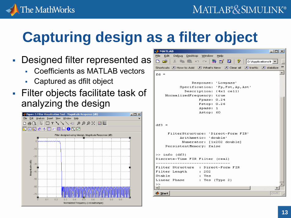
Capturing design as a filter objectDesigned filter represented as
Coefficients as MATLAB vectorsCaptured as dfilt object
Filter objects facilitate task of analyzing the design

14
Advantages of using filter objects
Consolidated visualization and analysis (fvtool)Trade-off analysis for filtering via various structures
Overloaded filter functionList of supported filter structures
Path to simulation and automatic code generationSimulink model Generate HDL code
Automatic estimation of computational complexityExamining the Simulink modelUse of cost function
15
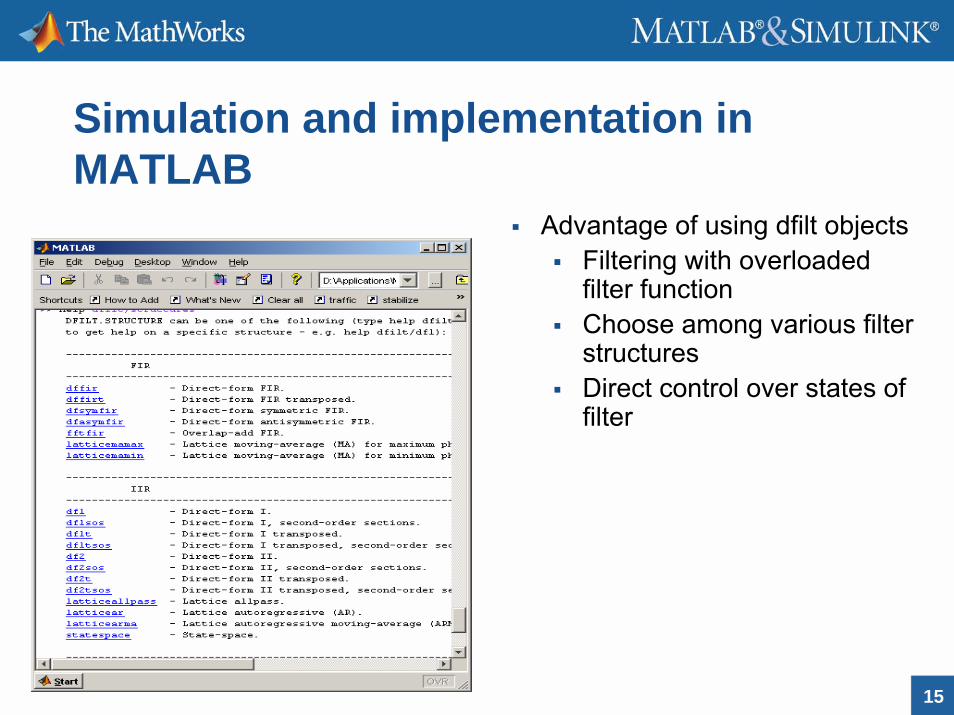
Simulation and implementation in MATLAB
Advantage of using dfilt objectsFiltering with overloaded filter functionChoose among various filter structuresDirect control over states of filter

16
Path to system-level simulation with Simulink & Signal Processing Blockset
Realizemdl method of filter objects
Generates a Simulink model representing the designed filter Implemented with delay, sum and gain blocks Reflects the structure of the filterHelps visualize the computational complexity

17
Automatic HDL code generation from filter objects
Functionality of Filter Design HDL CoderSupports both VHDL and Verilog codeCommand-line with generatehdl methodGUI-based as a target in fdatool

18
Estimation of filter computational complexity
Examine realized Simulink model to estimate number of additions & multiplications per sample Together with sampling frequency estimate Number of Operations per secondUse the Cost method of filter objectsImportant tool in studying design tradeoffs in terms of quality and complexity
Direct-Form FIR filter
Sampling Frequency (MHz) 100
Filter order 202
Number of Multipliers 642
Number of Adders 641
Number of States 630
Multiplications per input sample 42.8
Additions per input sample 42.7
Operations per second (MOPS) 8550

19
Multirate filters
An important class of filtersWidespread use in high data-rate signal processingMajor applications:
Wireless receiversDigital audio systems
Design challengeMeet spectral specification
Minimize aliasing effect Minimize the computational cost
Use efficient filter structures to avoid wasting processing power
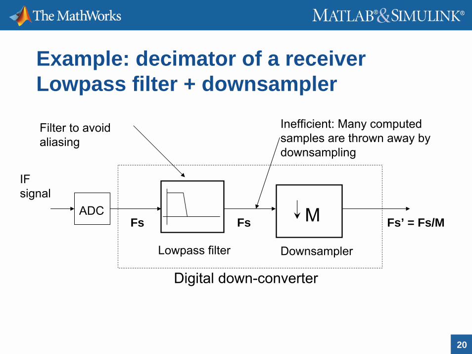
20
Example: decimator of a receiverLowpass filter + downsampler
Digital down-converter
ADC
Lowpass filter
IF signal
M
Downsampler
Fs’ = Fs/MFsFs
Inefficient: Many computed samples are thrown away by downsampling
Filter to avoid aliasing

21
Reestablish efficiency:Polyphase filter structure
H(z)≡
H0(zM)
z-1
H1(zM)
z-1
HM-1(zM)
Any lowpass filter
Can be represented in polyphase formatH(z) = b0 + b1z-1 + b2z-2 + … + bNz-N =
H0(zM) + z-1 H1(zM) + … + z-M+1 HM-1(zM)
M M
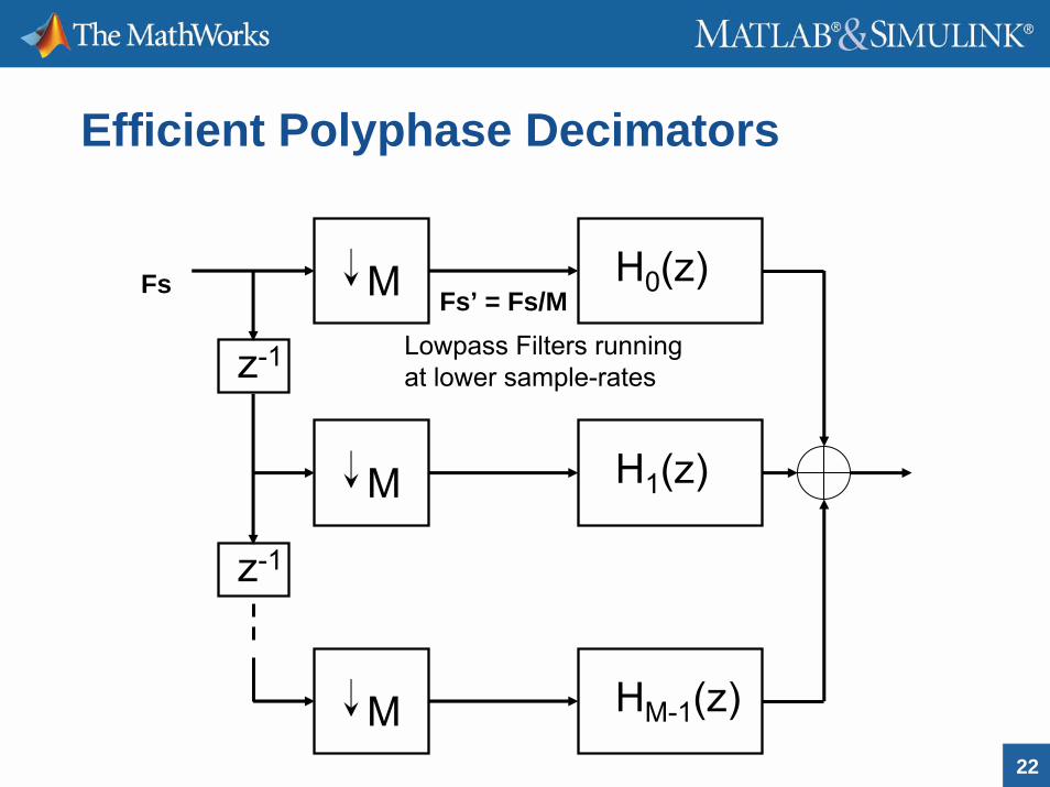
22
Efficient Polyphase Decimators
z-1
z-1
H0(z)M
H1(z)M
HM-1(z)M
Lowpass Filters running at lower sample-rates
Fs’ = Fs/MFs

23
Efficient Multirate FiltersInterpolators
Polyphase FIR interpolatorHold interpolatorLinear interpolatorFrequency Domain interpolatorCascaded Integrator-Comb (CIC) interpolator
DecimatorsPolyphase FIR decimatorTransposed polyphase FIR decimatorCIC decimator
Sample-rate convertersPolyphase FIR SRCPolyphase fractional decimatorPolyphase fractional interpolator

24
Featuring multistage CIC Filters
• Drawback: poor lowpass response
• Need cascading with a compensation filter
• Multistage cascades reduce computational cost
M1 M2Fs
M = M1*M2*…*Mk
MkFs’
• Very computationally efficient: No multipliers

25
Design of cascaded multistage decimators
Designfdesign objects
Implementation mfilt objects

26
CIC + multi-stage polyphase and half-band compensators: Filter response
CIC with 2-stage Compensator
Sampling Frequency (MHz) 100
Decimation Factor 4 x 2 X 2
Number of Multipliers 86
Number of Adders 94
Number of States 166
Multiplications per input sample 6.0625
Additions per input sample 12.125
Operations per second (MOPS) 1818

27
Adaptive filters
Tracking a desired signal by adapting a filter based on error between desired signal and filter outputApplications include:
Acoustic echo cancellationAdaptive Noise Canceling (ANC)Equalization in Digital CommunicationsActive Noise Control
Design challenges Maximize speed of convergenceMinimize steady-state error
H(z)input
x(n) e(n)error
d(n)desired signal
-output
y(n)

28
Adaptive Filtering Algorithmsin Filter Design Toolbox
Gradient-basedLMSNormalized LMSBlock LMS Delayed LMSAdjoint LMS
Sign AlgorithmsSigned-errorSigned-dataSigned-sign
Affine projectionDirect matrix inversionRecursive updatesBlock AP
Active noise controlFiltered X LMS
Recursive least-squaresRLS, RW-KalmanSliding-window RLSHouseholderHouseholder sliding-windowQR decomposition
Frequency-domainFDAFUnconstrained FDAFPartitioned-block FDAFUnconstrained PBFDAF
Fast algorithmsFTF, SWFTFGAL, Least-squares lattice

29
Using Adaptfilt filter object
Constructionhlms = adaptfilt.lms(7);
Filtering with overloaded filter functionCompute mean squared error
mselms = msesim(hlms,v2,x,M);msenlms = msesim(hnlms,v2,x,M);
Trade-off between convergence & steady state MSE

30
Spectral analysis
Time-frequency dualityGain insight from analyzing spectral contentPower spectral density as Fourier transform of signal auto-correlationSpectrum objects to study power spectrum
h= spectrum.periodogram;h =
EstimationMethod: 'Periodogram'FFTLength: 'NextPow2'WindowName: 'Rectangular'

31
Signal Processing Toolbox spectral analysis techniques
PeriodogramWelchMTM (Thomson multitaper method)BurgCovarianceModified CovarianceYule-WalkerMUSIC (Multiple Signal Classification)Eigenvector

32
Benefits of spectral objects
Estimating the spectral characteristics of systems operating on received signalsEffect of windowing and overlaps on power spectral estimateWintool

33
Fixed-Point Signal Processing
Link between algorithm development and hardware implementationLower cost: driver for using fixed-point processorsDesign challenges:
Conversion of design to fixed-point Model the effect of finite word lengths Ensure adherence to specifications before hardware prototyping
34
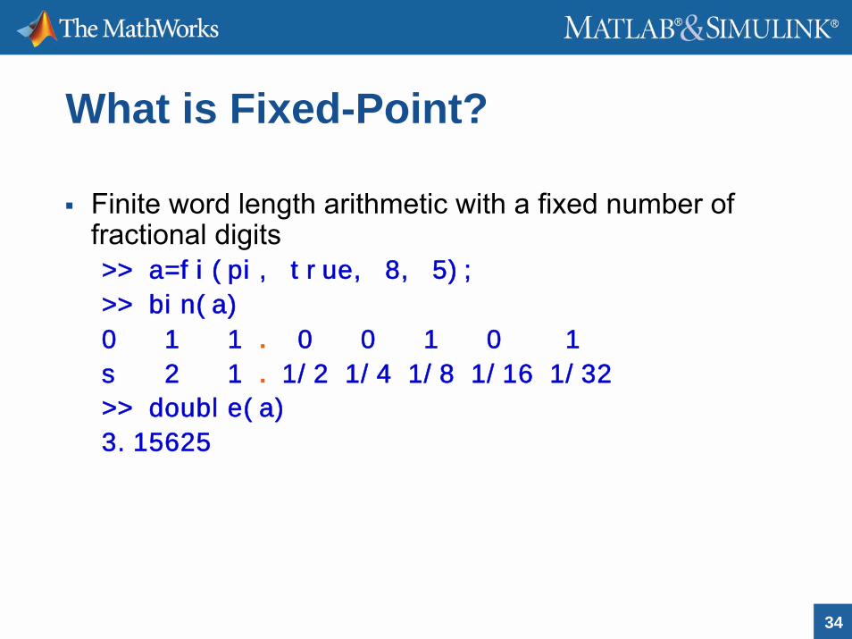
What is Fixed-Point?
Finite word length arithmetic with a fixed number of fractional digits>> a=fi(pi, true, 8, 5);
>> bin(a)
0 1 1 . 0 0 1 0 1
s 2 1 . 1/2 1/4 1/8 1/16 1/32
>> double(a)
3.15625

35
Fixed-Point in MATLAB®
Fixed-point numeric object fiBit-faithful fixed-point math in MATLABFixed-point algorithm development in MNatural MATLAB syntax
>> a=fi(0.1);>> bin(a)ans =
0110011001100110

36
Benefits of fi?
Quick fixed-point algorithm design and prototypingTest vectors for verification and validation Arbitrary word lengths (up to 65535 bits)Easier algorithm debug and visualizationEnables fixed-point in Filter Design ToolboxSupports Simulink To/From WorkspaceSupported in Embedded MATLAB Function block

37
Workflow of embedded fixed-point algorithm designer
1. Set-up simulation flow (initialization, loop, termination)2. Express your floating-point M-code algorithm
Focus on algorithmic integrity, proof of concept3. Simulate
iterate on algorithm trade-offs, validate against requirements4. Convert design to fixed-point
Focus of design viability based on implementation constraints 5. Simulate
iterate on implementation trade-offs, validate against original requirements
6. Generate code for hardware implementation7. Validate and verify design after hardware deployment

38
Conversion of design from floating to fixed-point
Steps involved with translating dynamic range of floating-point signal to convert design into fixed-point
1. Compute the range of the min/max logs2. Compute the integer part such that the range will not
overflow3. Compute the fraction length4. Construct the fixed-point numeric type object
1. A = max(abs(double(minlog(x))),abs(double(maxlog(x))));2. integer_part = ceil(log2(A));3. fraction_length = word_length - integer_part - double(logical(is_signed));4. T = numerictype(is_signed, word_length, fraction_length);

39
Conversion of filter to fixed-pointSet the fixed-point property of the dfilt object At command-line or in fdatool GUI
40
Path to C and HDL Implementation
System-level simulation and integrationSimulink, Signal Processing BlocksetSupport for single-rate, multirate adaptive filters
Realizemdl and block methodsAutomatic C code generation from Simulink
Real-Time WorkshopReal-Time Workshop Embedded Coder
Automatic HDL code generation for filtersFilter Design HDL CoderSupport for single-rate, multirate adaptive filters
41
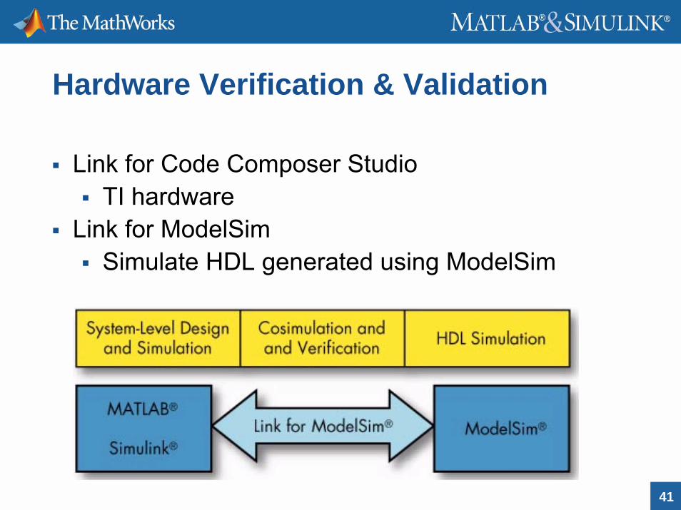
Hardware Verification & Validation
Link for Code Composer StudioTI hardware
Link for ModelSimSimulate HDL generated using ModelSim
42
Summary
MATLAB Signal Processing capabilities are productivity tools designed to respond to everyday challenges of researchers, scientists and engineers in all stages of development process
These include filter design, implementation, for single-rate, multirate and adaptive filters, spectral analysis, conversion of algorithms and filters to fixed-point and path to automatic hardware code generation and verification

43
For more information
About MATLAB and Simulink signal processing products
http://www.mathworks.com/products/product_listing/index.html
About relevant product demoshttp://www.mathworks.com/products/demos/index.html
User-contributed examples in MATLAB Centralhttp://www.mathworks.com/matlabcentral