matthew r. gilpin david b. scharfe university of southern
TRANSCRIPT

AFRL-RQ-ED-TR-2018-0026
High Energy Advanced Thermal Storage (HEATS)
Matthew R. Gilpin David B. Scharfe University of Southern California ERC Marcus P. Young Rebecca N. Webb In-Space Propulsion Branch Oregon State University Cascades
Air Force Research Laboratory (AFMC) AFRL/RQRS In-Space Propulsion Branch 1 Ara Drive Edwards AFB, CA 93524 November 2018 In-House Final Report
DISTRIBUTION STATEMENT A: Approved for public release; distribution unlimited. PA No. 18666
AIR FORCE RESEARCH LABORATORY AEROSPACE SYSTEMS DIRECTORATE
■ Air Force Materiel Command ■ United States Air Force ■ Edwards Air Force Base, CA 93524
STINFO COPY

- STINFO COPY - NOTICE AND SIGNATURE PAGE
Using Government drawings, specifications, or other data included in this document for any purpose other than Government procurement does not in any way obligate the U.S. Government. The fact that the Government formulated or supplied the drawings, specifications, or other data does not license the holder or any other person or corporation; or convey any rights or permission to manufacture, use, or sell any patented invention that may relate to them. This report was cleared for public release by the USAF 412 Test Wing (412 TW) Public Affairs Office (PAO) and is available to the general public, including foreign nationals. AFRL-RQ-ED-TR-2018-0026 HAS BEEN REVIEWED AND IS APPROVED FOR PUBLICATION IN ACCORDANCE WITH ASSIGNED DISTRIBUTION STATEMENT. FOR THE DIRECTOR: //Signed// //Signed// ____________________________ _______________________ MARCUS P. YOUNG JUSTIN W. KOO, Ph.D. Program Manager Technical Advisor, In-Space Propulsion Branch //Signed// ____________________________ Technical Advisor Rocket Propulsion Division This report is published in the interest of scientific and technical information exchange, and its publication does not constitute the Government’s approval or disapproval of its ideas or findings.

REPORT DOCUMENTATION PAGE Form Approved
OMB No. 0704-0188 Public reporting burden for this collection of information is estimated to average 1 hour per response, including the time for reviewing instructions, searching existing data sources, gathering and maintaining the data needed, and completing and reviewing this collection of information. Send comments regarding this burden estimate or any other aspect of this collection of information, including suggestions for reducing this burden to Department of Defense, Washington Headquarters Services, Directorate for Information Operations and Reports (0704-0188), 1215 Jefferson Davis Highway, Suite 1204, Arlington, VA 22202-4302. Respondents should be aware that notwithstanding any other provision of law, no person shall be subject to any penalty for failing to comply with a collection of information if it does not display a currently valid OMB control number. PLEASE DO NOT RETURN YOUR FORM TO THE ABOVE ADDRESS.
1. REPORT DATE (MM/DD/YYYY) 11/30/2018
2. REPORT TYPE Final Report
3. DATES COVERED (From - To) 12/11/2012 – 09/01/2018
4. TITLE AND SUBTITLE High Energy Advanced Thermal Storage (HEATS)
5a. CONTRACT NUMBER In-House
5b. GRANT NUMBER
5c. PROGRAM ELEMENT NUMBER
6. AUTHOR(S) Matthew R. Gilpin (University of Southern California); David B. Scharfe (ERC)
5d. PROJECT NUMBER
Marcus P. Young (AFRL/RQRS); and Rebecca N. Webb (Oregon State University Cascades)
5e. TASK NUMBER
5f. WORK UNIT NUMBER Q12G
7. PERFORMING ORGANIZATION NAME(S) AND ADDRESS(ES) 8. PERFORMING ORGANIZATION REPORT NO.
Air Force Research Laboratory (AFMC) In-Space Propulsion Branch (AFRL/RQRS) 1 Ara Drive Edwards AFB, CA 93524
9. SPONSORING / MONITORING AGENCY NAME(S) AND ADDRESS(ES) 10. SPONSOR/MONITOR’S ACRONYM(S) Air Force Research Laboratory (AFMC) AFRL/RQR
5 Pollux Drive 11. SPONSOR/MONITOR’S REPORT Edwards AFB, CA 93524 NUMBER(S) AFRL-RQ-ED-TR-2018-0026
12. DISTRIBUTION / AVAILABILITY STATEMENT DISTRIBUTION STATEMENT A. Approved for public release; distribution unlimited. 13. SUPPLEMENTARY NOTES PA Clearance No. 18666
14. ABSTRACT The High Energy Advanced Thermal Storage (HEATS) program focused on the development of a high temperature latent heat thermal energy storage medium as the primary energy storage onboard a bi-modal solar thermal microsatellite. A bi-modal thermal bus capable of providing propulsive and electric power to a spacecraft was previously identified as a promising architecture for microsatellites requiring a substantial ΔV. A review of existing technology showed that the use of high performance thermal energy storage is the enabling technology for such a bi-modal configuration and previous solar thermal studies have suggested the use of high temperature phase change materials (PCMs) such as silicon and boron. Prior to this program, developmental constraints and a lack of knowledge have prevented the inclusion of these materials in solar thermal designs and analysis has remained at the conceptual stage. The goal of the HEATS program was to experimentally investigate using silicon and boron as high temperature PCMs and determine overall technological feasibility. This report summarizes the key experimental findings of the program and identifies extant practical concerns associated with using silicon as a PCM. Ultimately, the HEATS program concluded that implementing high temperature latent heat thermal energy storage is technologically feasible and, with proper implementation, the performance benefits discussed in earlier conceptual studies are likely realizable.
15. SUBJECT TERMS Phase change materials; energy storage; silicon; boron; microsatellite; heliostats; solar furnaces; freezing
16. SECURITY CLASSIFICATION OF:
17. LIMITATION OF ABSTRACT
18. NUMBER OF PAGES
19a. NAME OF RESPONSIBLE PERSON
Marcus Young
a. REPORT Unclassified
b. ABSTRACT Unclassified
c. THIS PAGE Unclassified
SAR
33
19b. TELEPHONE NO (include area code)
Standard Form
298 (Rev. 8-98) Prescribed by ANSI Std. 239.18

This Page Intentionally Left Blank

i
Table of Contents 1.0 Introduction ................................................................................................................................................ 1
2.0 Experimental Testing ................................................................................................................................. 5
2.1 Solar Furnace ......................................................................................................................................... 5
2.2 Test Design and Procedure .................................................................................................................... 9
2.3 100% Fill Factor Testing...................................................................................................................... 11
2.4 Expansion Damage Mitigation ............................................................................................................. 13
2.5 Reduced Fill Factors ............................................................................................................................ 13
2.6 High Density Graphite ......................................................................................................................... 14
2.7 Partial Freezing .................................................................................................................................... 16
2.8 Experimental Testing Summary ........................................................................................................... 17
3.0 Computational Analysis .......................................................................................................................... 18
4.0 Future Work ............................................................................................................................................. 21
4.1 Container Design and Modeling .......................................................................................................... 21
4.2 Convective Coupling Analysis ............................................................................................................. 21
5.0 Conclusions .............................................................................................................................................. 22
References ....................................................................................................................................................... 24
List of Symbols, Abbreviations, and Acronyms ............................................................................................. 27

ii
List of Figures Figure 1: Relative ΔV Delivery for Representative Heat Exchanger Models vs. Burn Time for a Single Thruster Firing .................................................................................................................................................. 3 Figure 2: Transient Temperature Profiles for the “Boron - Diameter Reduction” STAR-CCM+ Model ............ 4 Figure 3: Two Stage Solar Furnace Path Diagram ......................................................................................... 6 Figure 4: USC Heliostat Mirror Array .............................................................................................................. 9 Figure 5: Photographs of the USC Solar Concentrator ..................................................................................... 7 Figure 6: Flux Maps Taken at the Experimental Location for the USC Solar Furnace .................................... 8 Figure 7: Power Delivery vs. Insolation for the USC Solar Furnace as a Function of Acceptable Spot Size ... 8 Figure 8: Cut-away Diagram of a Cylindrical Test Article Containing Silicon PCM and Boron Nitrate Liner ................................................................................................................................................................ 10 Figure 9: Photographs of Test Section Construction ...................................................................................... 10 Figure 10: Experimental Cooling Curves for the Test Section Described in Figure 8 ................................... 11 Figure 11: Photographs of 100% Fill Factor Tests ......................................................................................... 12 Figure 12: Experimental Heating Curve for 100% Fill Factor Test Sections ................................................. 12 Figure 13: Section Photographs of an 80% Fill Factor Test Article with Evidence of Flowing Silicon ........ 14 Figure 14: Cut-away Diagram of a Cylindrical Test Article with a Graphite Walled PCM Cavity ............... 15 Figure 15: Section Photographs of Graphite Walled Test Section Post Testing ............................................. 16 Figure 16: Experimental Data for Partial Freezing Tests ................................................................................ 17 Figure 17: Thermal Profiles Calculated by the In-House MATLAB Cooling Model for the Test Section Given in Figure 8 ............................................................................................................................................ 19 Figure 18: Comparison of MATLAB and Experimental Data for 100% Fill Factor Tests............................. 20 Figure 19: Comparison of MATLAB and Experimental Data for 80% Fill Factor Tests Between Trials ..... 20 Figure 20: Comparison of MATLAB and Experimental Data for 80% Fill Factor, Graphite Walled Test Sections ........................................................................................................................................................... 20

1
1.0 Introduction The High Energy Advanced Thermal Storage (HEATS) program was initiated by a 2009 review of microsatellite
propulsion technologies conducted by the Advanced Concepts Propulsion Group at the Air Force Research Laboratory [1] which surveyed available propulsion technologies in the context of a high performance microsatellite capable of a substantial ΔV while maintaining fast response times. The review showed that Solar Thermal Propulsion’s (STP) long known and unique combination of high thrust and high specific impulse (Isp) would be an enabling technology for the proposed mission scenario of a 200 kg ”inspector” satellite requiring an estimated total ΔV of 1.5–2 km/s. The review noted that while these large ΔV missions are feasible with electric propulsion, the response time for needed maneuvers would be several years; in keeping with the typical microsatellite goal of rapid response and lower cost, a STP system reduces this to a matter of days. It was the recommendation of this review to further investigate the feasibility of a microsatellite scale STP system.
Multiple research efforts have targeted a STP based spacecraft over the concept’s 50 year history due to the promise of high thrust and high efficiency. However, no solar thermal spacecraft have been flown to date. STP is traditionally viewed as an unproven technology with multiple tests programs canceled due to risk and budgetary reasons as opposed to technological hurdles [2]. Significant drawbacks frequently cited include the requirement of solar illumination at the time of propulsion and the difficulty associated with integrating a dedicated thermal collection mechanism into an existing spacecraft bus.
The HEATS program investigated the current state of STP technologies and found that at the microsatellite scale, typical concerns with implementing a STP system could be mitigated by combining the solar thermal propulsion sys- tem with a high performance thermal energy storage system (eliminating timing constraints on propulsive maneuvers) and a means of thermal-electric conversion (eliminating the ‘legacy’ PV system) [2, 3, 4, 5, 6, 7]. By creating a bi- modal system, the thermal energy system could provide both propulsive and electrical power for a satellite providing for additional mass savings and streamlined operation of a single power system.
A technology review showed that the majority of the technologies for a bi-modal STP system either have ready solutions or have previously been under investigation with the exception of high-performance latent heat thermal energy storage [2]. Thus, HEATS was focused on experimentally determining the feasibility of using latent heat thermal energy storage via molten elemental materials with the goal of providing a robust, high temperature and high density thermal energy storage solution with the potential to enable a new class of solar thermal microsatellites.
The HEATS effort produced the first experimental results targeting the use of molten silicon as a thermal energy storage media for spacecraft applications which highlighted multiple engineering challenges required for further technological advancement. These practical concerns, including convective coupling efficiency and the effects of asymmetrical freezing, were missing from the STP literature which has frequently mentioned silicon and boron as promising energy storage candidates. The program also highlighted the unique capabilities of a bi-modal solar thermal propulsion system as well as the unique spacecraft mission profile at the microsatellite scale where STP favorably trades with existing propulsion technologies.
Key elements of this investigation are summarized here, including the reasoning behind the bi-modal solar thermal microsatellite concept, the development of a new solar testing facility, computational modeling of convective coupling, and experimental results. It is the conclusion of the HEATS program that a bi-modal STP system is technologically feasible and can provide substantially larger ΔV than existing chemical systems while maintaining high thrust and maneuverability. [2]
A bi-modal thermal energy storage system, including both a direct thermal output (i.e.: heated propellant gas) and a converted electrical output, can be optimized for a variety of applications, both terrestrial and in-space. The motivating application for the HEATS program is that of a microsatellite which has a combined thermal propulsion and power system. The design goals of such a system have been discussed previously,[3, 4, 5, 6] and will only be briefly summarized here.
To favorably compete with existing technology on a 100 kg microsatellite (note that HEATS considered a smaller spacecraft than the motivating literature review), a bi-modal STP system must provide 100 W of continuous electrical power and have continuously available propulsion on the order of 1 N with an Isp of 300–400 s. This level of performance can be achieved with an ammonia based solar thermal rocket, which has significant practical advantages over a rocket using often-proposed cryogenic hydrogen propellant. To achieve adequate thermal storage temperatures (i.e. propellant temperatures), a solar collection mechanism with a concentration ratio of 10,000:1 is necessary and fiber optic coupling to the storage device is required to separate concentrator pointing from spacecraft attitude. Both of these technologies appear to be feasible based upon the current state of technological development [2, 5]. Additional technological requirements such as advanced insulation and high performance thermal-electric
DISTRIBUTION STATEMENT A: Approved for public release; distribution unlimited. PA No. 18666

2
conversion also appear to have readily applicable solutions which can be drawn from previous research efforts [6, 7].
Existing literature from over 50 years of solar thermal propulsion shows that the largest extant technological challenge for a bi-modal STP system is high performance thermal energy storage. Previous solar thermal efforts have included sensible heat thermal energy storage in their design by using high temperature materials such as graphite and boron carbide [8, 9]. High energy densities can be achieved in this manner, however, the large ΔT required (ΔT of 600 K for 1.5 MJ/kg in graphite) can result in reduced thruster performance, increased thermal stress on the spacecraft, and lower thermal-electric energy conversion efficiency. To avoid the drawbacks of sensible heat energy storage, augmenting a STP system with latent heat thermal energy
storage is proposed. A new class of phase change materials (PCMs) must be developed that have a properly matched melting temperature and a sufficiently high latent heat capacity. A survey of candidate PCMs identified silicon and boron as the thermal storage materials of choice; several other candidate materials are listed in Table 1 for comparison. For the HEATS program, boron was identified as an ideal far-term storage material due to its substantial heat of fusion and a melting temperature close to the optimal performance point for an ammonia based STP rocket [15]. It must be noted, however, that limited research has gone into simply handling boron in the molten state and the high melting temperature increases the cost of ground experiments by an order of magnitude. Therefore, this research program focused on silicon as a near term latent heat storage option capable of providing storage capability on par with sensible heat systems with moderate thrust and specific heat values.
Table 1: Potential High Temperature Phase Change Materials
Material specific references are given when applicable, otherwise, values are taken from database sources [10, 11, 12]. Thermal conductivity values given in italics are the closest available measurement to Tmelt.
Previous solar thermal propulsion research efforts have also noted the possibility of utilizing boron and silicon as
PCMs [16, 17, 18, 19]. However, development was limited to brief conceptual studies which primarily compared material properties. Schedule constraints and the risk of a novel technology outweighed the performance benefits of latent heat thermal energy storage in these research efforts and thus, further work was focused on sensible heat materials. These previous studies also did not consider the beneficial effects of convective coupling to a latent heat medium,
which can provide further propulsive benefits relative to a sensible heat source. A quasi-isothermal energy release surrounding a propellant channel in a latent heat system results in a more advantageous convective environment, maintaining propellant exit temperatures and a higher ”effective” energy storage density (i.e. maximum energy storage capability vs. energy that can be beneficially transferred into propellant).
To create a point of comparison, the HEATS program performed a multi-physics simulation of a sample heat exchanger passage as proposed for the Integrated Solar Upper Stage (ISUS) Program. The ISUS program is the most- realized bi-modal solar thermal experimental program to-date which created an integrated receiver-absorber-converter module for a 2000 kg spacecraft utilizing graphite sensible heat thermal energy storage [9, 20, 21]. The

3
simulation, which has previously been discussed, began by creating a sensible heat channel that mimics the performance of the ISUS program [2]. Three other channels were also simulated which made use of Boron based thermal energy storage. One system maintained the same mass as the ISUS module and the others were sized to provide the same effective energy storage density as the ISUS system but with reductions in heat exchanger length and diameter, respectively. The results of these models are given in Figure 1.
The most obvious performance comparison in Figure 1 is comparing the sensible heat ISUS approximation with the constant mass simulation. It is possible to rapidly increase the total ΔV for a sustained burn since, by weight, Boron phase change energy storage offers significantly more energy density than graphite. However, the reduced mass and reduced diameter cases are more interesting with respect to the concept of effective energy storage density. The outsized benefits often considered for PCMs, such as that shown in the “constant mass” simulation, target burn profiles that don’t match mission requirements.
Figure 1: Relative ΔV Delivery for Representative Heat Exchanger Models vs. Burn Time for a Single Thruster Firing
The reduced length and diameter results given in Figure 1 show that for burns lasting up to 400 s, the same relative
ΔV is maintained despite dramatic reductions in size. The length and diameter models took two different approaches to reducing total heat exchanger mass and reduced overall heat exchanger mass by 70% and 60% respectively while maintaining similar performance. These models show that dramatic performance improvements are possible with PCMs when considering analysis beyond simple material properties. A visual example of this beneficial convective coupling is given in Figure 2 which shows transient temperature profiles in a simulated heat exchanger package.

4
Figure 2: Transient Temperature Profiles for the “Boron - Diameter Reduction” STAR-CCM+ Model Modeling geometry and transient temperature profiles for the “Boron - Diameter Reduction” STAR-CCM+ model results given in Figure 1. Model geometry is axisymmetric and represents the red outlined region of the cylindrical heat exchanger passage. Hydrogen flow through the passage is from left to right and dimensions are given in millimeters. Note that up to 300 seconds, the propellant exit temperature remains constant as sufficient passage length is maintained with an optimal ΔT due to the isothermal heat release during the phase change process.

5
When all relevant technologies are combined into the proposed bi-modal system, a greater than 50% ΔV increase over chemical systems is possible while maintaining response times measured in days [2]. The focus of the HEATS program was to target the microsatellite platform which amplifies the benefits of STP. The target spacecraft scale is below the range of existing bi-propellant options and is unable to generate sufficient electrical power for high-thrust electrical propulsion. Multiple challenges still remain to ultimately produce a proof-of-concept demonstration of the proposed bi-modal solar thermal technology. However, the component technologies required for a viable bi- modal microsatellite have all reached sufficient technological maturity to consider them viable with the exception of high performance latent heat thermal energy storage. The goal of HEATS was to determine the basic feasibility of this enabling technology via experimental investigation, and to facilitate the future development of a bi-modal solar thermal microsatellite.
2.0 Experimental Testing
High temperature latent heat thermal energy storage is frequently discussed in both the solar thermal and thermophotovoltaic literature [19, 22, 23, 24]. Molten silicon, in particular, has been identified in thermophotovoltaic research efforts as an “ideal” thermal storage material [23]. Despite a continued interest, no published experimental efforts have investigated molten silicon thermal energy storage and all work has remained in the conceptual phase. This lack of development has precluded the use of silicon or boron in solar thermal development projects in favor of simpler, lower performance, sensible heat designs.
To remedy this lack of knowledge, the HEATS program centered on an experimental approach. The experimental effort represents the most substantive physical investigation into high temperature latent heat thermal energy storage for spacecraft applications to date and resulted in the construction of a new solar furnace facility at the University of Southern California and a practical knowledge base not present in existing STP literature. 2.1 Solar Furnace
A solar furnace was built to support molten silicon experiments and uncover the practical concerns associated with the technology. A solar furnace was used as opposed to a bench top system to ensure that experimental analysis maintained correlation to the ultimate use in a STP system. In particular, a solar furnace emphasized analysis concerning a “point” input of thermal energy in the form of concentrated sunlight as would be seen on-board a spacecraft which creates unique concerns with respect to thermal gradients and asymmetrical freezing in the PCM.
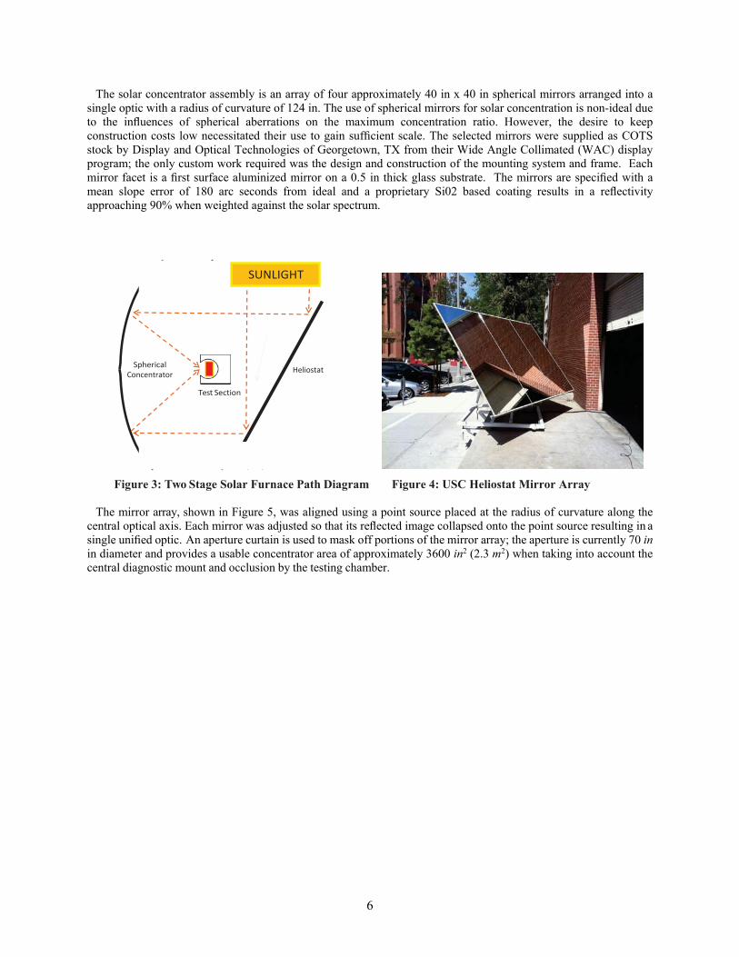
The current USC solar furnace is a two stage system as diagrammed in Figure 3. First, a computer controlled heliostat is used to re-direct sunlight into the solar concentrator mirror array. The concentrated sunlight is then focused through a fused quartz window into the testing chamber. Test sections loaded into the chamber can be held in a vacuum or a low pressure controlled environment to reduce convective losses and repress material interactions and oxidation.
The heliostat consists of an altitude-azimuth tracking drive, computer control system and 12 ft x 8 ft second surface mirror array. To keep costs low, the tracking drive was obtained as surplus from previous AFRL efforts and refurbished [25]. Open loop tracking rate control is performed using a supplied target vector and the local solar vector computed in real time via published algorithms [26, 27]. The heliostat mirror array, shown in Figure 4, is supported by an aluminum I-beam structure and uses aluminum honeycomb panels as a support surface for eight 4 ft x4 ft second surface float glass mirrors. The mirror array’s size was determined by the maximum space allowed at the current location and coverage requirements set by the concentrator. The placement of the solar furnace facility allows for approximately 4 hours of sunlight coverage per day.
6
The solar concentrator assembly is an array of four approximately 40 in x 40 in spherical mirrors arranged into a single optic with a radius of curvature of 124 in. The use of spherical mirrors for solar concentration is non-ideal due to the influences of spherical aberrations on the maximum concentration ratio. However, the desire to keep construction costs low necessitated their use to gain sufficient scale. The selected mirrors were supplied as COTS stock by Display and Optical Technologies of Georgetown, TX from their Wide Angle Collimated (WAC) display program; the only custom work required was the design and construction of the mounting system and frame. Each mirror facet is a first surface aluminized mirror on a 0.5 in thick glass substrate. The mirrors are specified with a mean slope error of 180 arc seconds from ideal and a proprietary Si02 based coating results in a reflectivity approaching 90% when weighted against the solar spectrum.
Figure 3: Two Stage Solar Furnace Path Diagram Figure 4: USC Heliostat Mirror Array
The mirror array, shown in Figure 5, was aligned using a point source placed at the radius of curvature along the central optical axis. Each mirror was adjusted so that its reflected image collapsed onto the point source resulting in a single unified optic. An aperture curtain is used to mask off portions of the mirror array; the aperture is currently 70 in in diameter and provides a usable concentrator area of approximately 3600 in2 (2.3 m2) when taking into account the central diagnostic mount and occlusion by the testing chamber.
Spherical Concentrator
Heliostat
Test Section
SUNLIGHT

7
Figure 5: Photographs of the USC Solar Concentrator
Photographs of the mirror array during construction (left) and as seen through the 70 inch aperture curtain. The mirrors are blue during construction due to a protective plastic film applied before shipment. Note the testing chamber seen in the middle of the concentrator array in the photograph on the right.
The testing chamber for the USC solar furnace is a 6 in CF cross connected by an extension to a vacuum chamber outside the area of the solar concentrator. Concentrated sunlight enters the testing chamber through a 6-in diameter, 0.25 in thick fused quartz window. The testing chamber is instrumented with both Type K and Type C thermocouples for temperature measurement and an emissivity sensing non-contact infrared thermometer is also available. The infrared thermometer has been calibrated by the manufacturer for use through the quartz chamber window.
The solar furnace was characterized for total input power as a function of local solar insolation as well as for individual component efficiencies. In addition to total power delivered, a CCD based flux mapping technique was applied to determine solar flux profiles as well as the peak concentration ratios [2]. Figures 6 and 7 show representative flux maps as well as total power delivery with peak concentration ratios in excess of 4000:1 and typical total power delivery of approximately 750 W.

8
Figure 6: Flux Maps Taken at the Experimental Location for the USC Solar Furnace
Iso lines are given in number of suns.
Figure 7: Power Delivery vs. Insolation for the USC Solar Furnace as a Function of Acceptable Spot Size
Values include losses from the quartz chamber window. Typical insolation at the facility is between 750-950 W/m2 depending on atmospheric conditions.

9
2.2 Test Design and Procedure
The primary goal of testing in the USC solar furnace was to create molten silicon and analyze freezing effects [2]. Experiments used cylindrical test sections with the geometry shown in Figure 8. The ultimate cylindrical geometry was the product of over 80 investigative solar furnace tests and was chosen for simplified modeling and ease of in-house manufacture. Since silicon is highly reactive in the liquid state, materials studies were conducted identifying boron nitride (BN) as a promising container material due to a self limiting reaction with molten silicon and synergy with potential molten boron container designs [2, 3, 4, 5, 6, 7]. Test sections are sized for a minimum solar furnace input power of 750 W and were intended to provide simplified system characterization and model validation as opposed to maximum thermal efficiency.
Test section construction began by loading silicon into a cylindrical HBC grade BN container with a friction fit lid. HBC boron nitride was selected since it lacks a boric oxide binder which can precipitate at high temperatures [28]. The BN inner container was inserted into a graphite sleeve which uses a press fit to seal both the graphite and BN lid. Early furnace testing utilized either silicon powder or small silicon chips to load the BN container. With these materials, packing difficulty resulted in maximum silicon fill factors of approximately 60%. While these experiments were sized to contain over 30 g of silicon, the low fill factor resulted in little correlation with predictive models. As a result, experimental size was not limited by solar furnace power, but by the availability of affordable silicon rod stock. The primary insulation for test articles consists of commercially available Rescor 760 castable ceramic. This ZrO2 ceramic product is low cost, easy to cast, and has an acceptably low thermal conductivity (0.93 W/mK). However, the use of ZrO2 ceramic in contact with graphite places limits on the experiment due to reactivity at elevated temperatures. ZrO2 and graphite react at temperatures as low as 1400 K. At peak experimental temperatures, the equilibrium pressure of the reaction is approximately 40 torr [29]. Before this reaction was identified, tests resulted in irreversible contamination of the quartz chamber entrance window. To prevent quartz window contamination at the expense of convection losses, tests were operated in an environment of 150 torr of argon. Testing using a pure BN system would allow for low pressure operation without quartz window damage. However, the high cost and relatively low thermal conductivity of BN compared with graphite makes this approach impractical. Test sections were instrumented by embedding Type K thermocouples into the cast ceramic and by running a bare wire Type C thermocouple through the ceramic sting mount. Photographs of the test section construction process are shown in in Figure 9.
The first step in the furnace testing procedure was to bake out new test sections under vacuum at approximately 500 K using a 1000 W spot lamp. This process evaporates proprietary water based binders from the Rescor 760 ceramic which can fog the quartz chamber window and decrease power delivery. The chamber was then backfilled to 150 torr of argon and solar furnace power was gradually increased until the test section reached thermal equilibrium. At this point, a shutter curtain was used to cut solar furnace power and the cooling curve for the test section was recorded.

10
Figure 8: Cut-away Diagram of a Cylindrical Test Article Containing Silicon PCM and Boron Nitrate Liner
Diagram of a cylindrical test article sized for 9 g of silicon showing materials, components, and overall experimental geometry. Dimensions given in inches.
Figure 9: Photographs of Test Section Construction
Montage of test section construction photos. Clockwise from top-left: Silicon rod sample, inner components after machining, silicon placement in BN sleeve, inner components supported via slip-fit before compression into place, assembly before ceramic casting, wet ceramic casting showing clamps for thermocouple support, completed test section face, completed test section body.

11
2.3 100% Fill Factor Testing
The first round of molten silicon testing was performed on sections with a 100% silicon fill factor. Silicon rods were precision cut to be an exact fit for the BN PCM container leaving no voids or gaps in the test articles and maximizing energy storage potential. Figure 10 shows experimental data taken during one such test. The phase change process occurs from approximately t = 30 s to t = 120 s and demonstrates the relative temperature stability expected from a latent heat system. The curves “Cycle 1” and “Cycle 2” are taken from the same test section across two back-to-back cycles.
Figure 10: Experimental Cooling Curves for the Test Section Described in Figure 8
Experimental data taken with a Type C thermocouple as labeled in Figure 8. Both traces are from the same test section in back to back cycles.
Note that “Cycle 1” exhibits a temperature spike at t = 108 s. This spike corresponded with cracking of the test
section due to asymmetric expansion of liquid silicon trapped within the partially frozen silicon bulk. Expansion results in both increased contact pressure within the container and a shift in container geometry producing higher recorded temperatures. Repeated tests also demonstrated similar temperature profiles and cracking behavior. Figure 11 shows photographs taken during the testing process for a 100% fill factor test section illustrating container failure.
In addition to demonstrating the difficulties posed by silicon expansion, 100% fill factor testing illustrated other operational concerns. During test section heating, a rapid jump in temperature is apparent when the rear of the test section approaches 1500 K. A temperature curve during the heating process is given in Figure 12 which illustrates this temperature spike in the absence of increasing solar furnace power. This temperature spike corresponds to the phase transition of the silicon bulk and the rising rear temperature is a function of a step change in silicon’s thermal conductivity from approximately 18.5 W/mK at the melting point to 51 W/mK once liquid [30]. In order to account for this change, thermal designs must consider the lower thermal conductivity value to ensure sufficient heat conduction throughout. In this testing series, relatively small reductions in total solar furnace power have produced incomplete melting when the system was unable to overcome this thermal conductivity barrier.

12
Figure 11: Photographs of 100% Fill Factor Tests Photographs taken during 100 % fill factor tests. A) Test section before heating. B) Test section immediately after power cutoff. C) Infrared photograph taken during solar heating showing a large crack formed in the test section during the previous cooling cycle. Note the relative size and intensity of the solar furnace input. D) Image of the interior of the crucible after testing showing decreased silicon density after freezing.
Figure 12: Experimental Heating Curve for 100% Fill Factor Test Sections
Initial experimental heating curve for a test section at a 100% silicon fill factor. Note the four distinct heating regions as solar furnace power was gradually increased and a 5th rapid rise in temperature corresponding to complete melting of the silicon PCM.
13
2.4 Expansion Damage Mitigation
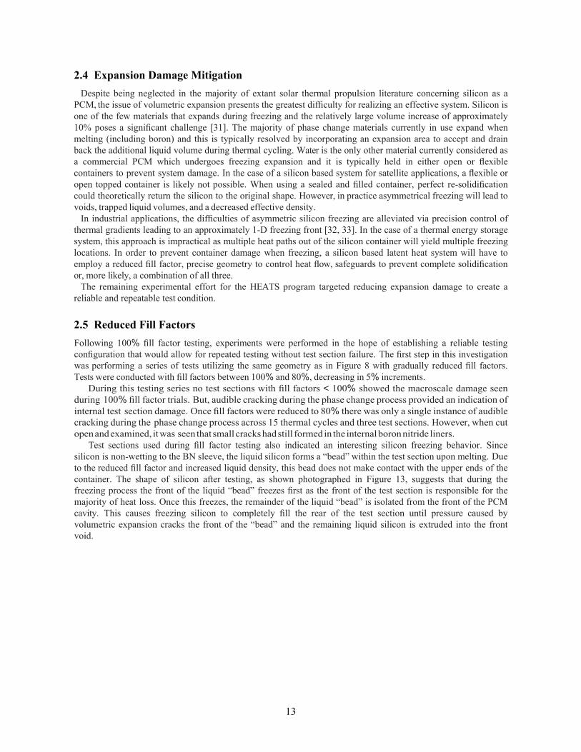
Despite being neglected in the majority of extant solar thermal propulsion literature concerning silicon as a PCM, the issue of volumetric expansion presents the greatest difficulty for realizing an effective system. Silicon is one of the few materials that expands during freezing and the relatively large volume increase of approximately 10% poses a significant challenge [31]. The majority of phase change materials currently in use expand when melting (including boron) and this is typically resolved by incorporating an expansion area to accept and drain back the additional liquid volume during thermal cycling. Water is the only other material currently considered as a commercial PCM which undergoes freezing expansion and it is typically held in either open or flexible containers to prevent system damage. In the case of a silicon based system for satellite applications, a flexible or open topped container is likely not possible. When using a sealed and filled container, perfect re-solidification could theoretically return the silicon to the original shape. However, in practice asymmetrical freezing will lead to voids, trapped liquid volumes, and a decreased effective density.
In industrial applications, the difficulties of asymmetric silicon freezing are alleviated via precision control of thermal gradients leading to an approximately 1-D freezing front [32, 33]. In the case of a thermal energy storage system, this approach is impractical as multiple heat paths out of the silicon container will yield multiple freezing locations. In order to prevent container damage when freezing, a silicon based latent heat system will have to employ a reduced fill factor, precise geometry to control heat flow, safeguards to prevent complete solidification or, more likely, a combination of all three.
The remaining experimental effort for the HEATS program targeted reducing expansion damage to create a reliable and repeatable test condition.
2.5 Reduced Fill Factors
Following 100% fill factor testing, experiments were performed in the hope of establishing a reliable testing configuration that would allow for repeated testing without test section failure. The first step in this investigation was performing a series of tests utilizing the same geometry as in Figure 8 with gradually reduced fill factors. Tests were conducted with fill factors between 100% and 80%, decreasing in 5% increments.
During this testing series no test sections with fill factors < 100% showed the macroscale damage seen during 100% fill factor trials. But, audible cracking during the phase change process provided an indication of internal test section damage. Once fill factors were reduced to 80% there was only a single instance of audible cracking during the phase change process across 15 thermal cycles and three test sections. However, when cut open and examined, it was seen that small cracks had still formed in the internal boron nitride liners.
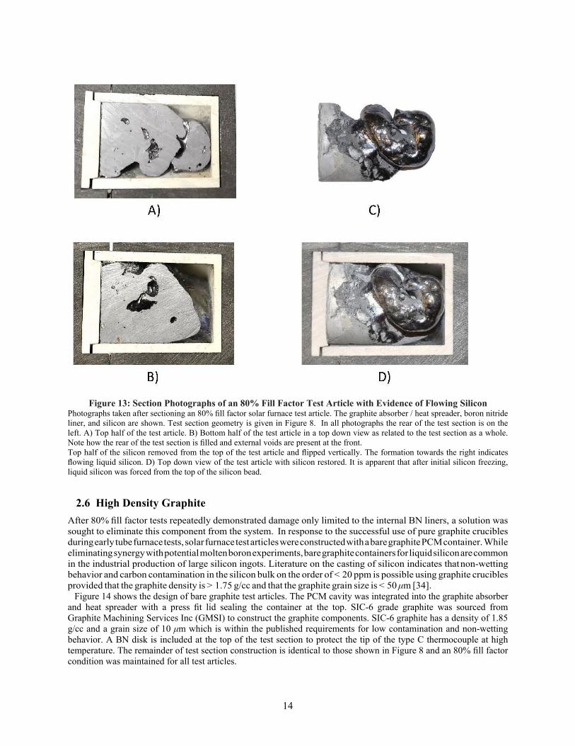
Test sections used during fill factor testing also indicated an interesting silicon freezing behavior. Since silicon is non-wetting to the BN sleeve, the liquid silicon forms a “bead” within the test section upon melting. Due to the reduced fill factor and increased liquid density, this bead does not make contact with the upper ends of the container. The shape of silicon after testing, as shown photographed in Figure 13, suggests that during the freezing process the front of the liquid “bead” freezes first as the front of the test section is responsible for the majority of heat loss. Once this freezes, the remainder of the liquid “bead” is isolated from the front of the PCM cavity. This causes freezing silicon to completely fill the rear of the test section until pressure caused by volumetric expansion cracks the front of the “bead” and the remaining liquid silicon is extruded into the front void.
14
Figure 13: Section Photographs of an 80% Fill Factor Test Article with Evidence of Flowing Silicon
Photographs taken after sectioning an 80% fill factor solar furnace test article. The graphite absorber / heat spreader, boron nitride liner, and silicon are shown. Test section geometry is given in Figure 8. In all photographs the rear of the test section is on the left. A) Top half of the test article. B) Bottom half of the test article in a top down view as related to the test section as a whole. Note how the rear of the test section is filled and external voids are present at the front. Top half of the silicon removed from the top of the test article and flipped vertically. The formation towards the right indicates flowing liquid silicon. D) Top down view of the test article with silicon restored. It is apparent that after initial silicon freezing, liquid silicon was forced from the top of the silicon bead.
2.6 High Density Graphite
After 80% fill factor tests repeatedly demonstrated damage only limited to the internal BN liners, a solution was sought to eliminate this component from the system. In response to the successful use of pure graphite crucibles during early tube furnace tests, solar furnace test articles were constructed with a bare graphite PCM container. While eliminating synergy with potential molten boron experiments, bare graphite containers for liquid silicon are common in the industrial production of large silicon ingots. Literature on the casting of silicon indicates that non-wetting behavior and carbon contamination in the silicon bulk on the order of < 20 ppm is possible using graphite crucibles provided that the graphite density is > 1.75 g/cc and that the graphite grain size is < 50 μm [34].
Figure 14 shows the design of bare graphite test articles. The PCM cavity was integrated into the graphite absorber and heat spreader with a press fit lid sealing the container at the top. SIC-6 grade graphite was sourced from Graphite Machining Services Inc (GMSI) to construct the graphite components. SIC-6 graphite has a density of 1.85 g/cc and a grain size of 10 μm which is within the published requirements for low contamination and non-wetting behavior. A BN disk is included at the top of the test section to protect the tip of the type C thermocouple at high temperature. The remainder of test section construction is identical to those shown in Figure 8 and an 80% fill factor condition was maintained for all test articles.

15
Figure 14: Cut-away Diagram of a Cylindrical Test Article with a Graphite Walled PCM Cavity
Cutaway diagram for test sections with a graphite walled PCM cavity. Note the presence of a small cutout in the outer wall of the graphite container. This was added as a retention mechanism after repeated failures caused by a slight negative draft machined outer wall of test sections. This draft, coupled with differential thermal expansion, would separate the two components of the container. Dimensions are given in inches. Test sections constructed using SIC-6 graphite exhibited no audible cracking and showed no damage after multiple
freezing cycles. However, test sections exhibited behavior indicating wetting by liquid silicon which is in contrast to predictions made in the literature. An additional test section was constructed substituting B325 industrial graphite which is outside the recommended specifications for density and grain size. Test section performance and silicon behavior for this lower density graphite was qualitatively identical.

16
Figure 15 shows the interior of a SIC-6 test section after melting in the solar furnace. Like the previous tests
using BN liners, there were voids apparent in the silicon bulk. However, it was evident in these tests that silicon had been wicked into the corners of the test article suggesting wetting behavior. This wicking behavior could be beneficial in a spacecraft system. Unlike BN lined tests which formed a central mass of liquid silicon, pure graphite containers could keep liquid silicon and the subsequent freezing process along the walls of the container. This would aid in overall heat transfer and maintain a central void to take up silicon expansion.
Figure 15: Section Photographs of Graphite Walled Test Section Post Testing
Photographs taken after sectioning a test article with a graphite walled PCM cavity. Note the silicon wicked into the upper corners in the front of the test section (center of image) indicating wetting behavior. This is in contrast to the behavior seen in Figure 13.
2.7 Partial Freezing
Another potential method for mitigating test section damage is to only allow for partial freezing of the silicon by re-introducing power to the system before complete solidification. This was attempted using a test section with a 100% fill factor and power was returned to the test section after 50, 60, and 70 seconds with temperature data given in Figure 16. All three of these intervals were successful and the test section indicated no audible cracking or physical container damage. Since it is estimated that the phase change process begins approximately 30 seconds after cutting solar furnace power, the longest 70 second freezing interval represents roughly 45% of the total phase change process length and the total energy storage achievable in the test section is reduced accordingly.
This damage prevention method could potentially be applied for flight systems, provided the duty cycle can
be matched to the eclipse period on orbit. However, it proves problematic for solar furnace ground demonstrations. Since crucible failure is assured when the experiment is terminated, a limited number of cycles is possible with each test section. Testing was further constrained by the limited experimental time afforded by the placement of the USC solar furnace facility.

17
Figure 16: Experimental Data for Partial Freezing Tests
Experimental data demonstrating successful partial freezing trials compared with experimental data with no power restoration. A star marks the point where power is restored in each trial. The grey shaded region is a composite of all 100 % fill factor trials.
2.8 Experimental Testing Summary
Testing performed using the USC Solar Furnace successfully produced samples of molten silicon via concentrated sunlight. These experiments ultimately highlighted the asymmetry of the silicon freezing process as a major practical challenge in the implementation of using silicon as a PCM which was previously absent from the STP literature. Management of the silicon freezing process has been identified as the primary technological hurdle in the design of a molten silicon based energy storage system and multiple methods for mitigating freezing expansion damage in a cylindrical container were explored. Satisfactory results were obtained by reducing the total PCM cavity fill factor to 80% and constructing test sections from high density graphite.
18
±
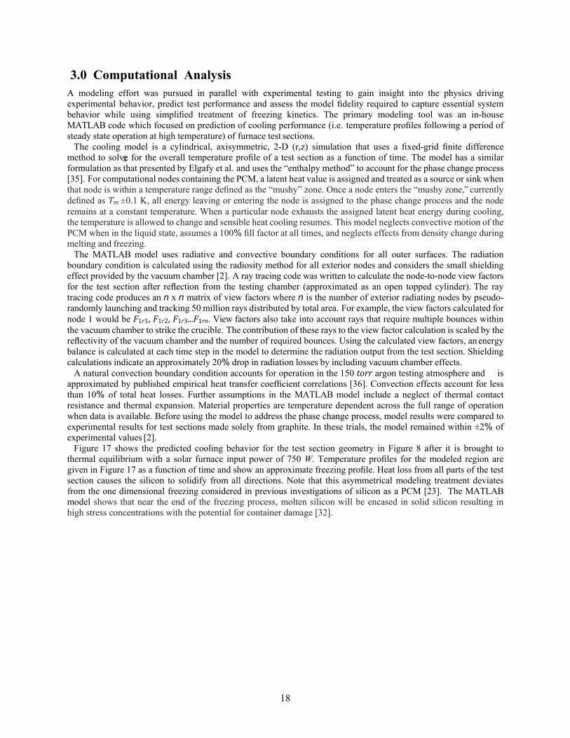
3.0 Computational Analysis A modeling effort was pursued in parallel with experimental testing to gain insight into the physics driving experimental behavior, predict test performance and assess the model fidelity required to capture essential system behavior while using simplified treatment of freezing kinetics. The primary modeling tool was an in-house MATLAB code which focused on prediction of cooling performance (i.e. temperature profiles following a period of steady state operation at high temperature) of furnace test sections.
The cooling model is a cylindrical, axisymmetric, 2-D (r,z) simulation that uses a fixed-grid finite difference method to solve for the overall temperature profile of a test section as a function of time. The model has a similar formulation as that presented by Elgafy et al. and uses the “enthalpy method” to account for the phase change process [35]. For computational nodes containing the PCM, a latent heat value is assigned and treated as a source or sink when that node is within a temperature range defined as the “mushy” zone. Once a node enters the “mushy zone,” currently defined as Tm±0.1 K, all energy leaving or entering the node is assigned to the phase change process and the node remains at a constant temperature. When a particular node exhausts the assigned latent heat energy during cooling, the temperature is allowed to change and sensible heat cooling resumes. This model neglects convective motion of the PCM when in the liquid state, assumes a 100% fill factor at all times, and neglects effects from density change during melting and freezing.
The MATLAB model uses radiative and convective boundary conditions for all outer surfaces. The radiation boundary condition is calculated using the radiosity method for all exterior nodes and considers the small shielding effect provided by the vacuum chamber [2]. A ray tracing code was written to calculate the node-to-node view factors for the test section after reflection from the testing chamber (approximated as an open topped cylinder). The ray tracing code produces an n x n matrix of view factors where n is the number of exterior radiating nodes by pseudo- randomly launching and tracking 50 million rays distributed by total area. For example, the view factors calculated for node 1 would be F1r1,F1r2,F1r3...F1rn. View factors also take into account rays that require multiple bounces within the vacuum chamber to strike the crucible. The contribution of these rays to the view factor calculation is scaled by the reflectivity of the vacuum chamber and the number of required bounces. Using the calculated view factors, an energy balance is calculated at each time step in the model to determine the radiation output from the test section. Shielding calculations indicate an approximately 20% drop in radiation losses by including vacuum chamber effects.
A natural convection boundary condition accounts for operation in the 150 torr argon testing atmosphere and is approximated by published empirical heat transfer coefficient correlations [36]. Convection effects account for less than 10% of total heat losses. Further assumptions in the MATLAB model include a neglect of thermal contact resistance and thermal expansion. Material properties are temperature dependent across the full range of operation when data is available. Before using the model to address the phase change process, model results were compared to experimental results for test sections made solely from graphite. In these trials, the model remained within ±2% of experimental values [2].
Figure 17 shows the predicted cooling behavior for the test section geometry in Figure 8 after it is brought to thermal equilibrium with a solar furnace input power of 750 W. Temperature profiles for the modeled region are given in Figure 17 as a function of time and show an approximate freezing profile. Heat loss from all parts of the test section causes the silicon to solidify from all directions. Note that this asymmetrical modeling treatment deviates from the one dimensional freezing considered in previous investigations of silicon as a PCM [23]. The MATLAB model shows that near the end of the freezing process, molten silicon will be encased in solid silicon resulting in high stress concentrations with the potential for container damage [32].

19
t = 20 s
t = 60 s t = 80 s
t = 120 s
t = 40 s
t = 100 s
Figure 17: Thermal Profiles Calculated by the In-House MATLAB Cooling Model for the Test Section Given in Figure 8
Thermal profiles as a function of time calculated by the in-house MATLAB model for the test section given in Fig. 8. Note that the model is axisymmetric so the red outlined region of the cutaway drawing is the region represented by the thermal maps. Also note that grey is used in the thermal maps to represent liquid silicon and it is apparent that liquid silicon will become trapped during the freezing process.
The results of the MATLAB model compared with 100% fill factor data are given in Figure 18. The model follows
the profile of the experimental data but exhibits a slightly higher cooling rate. It is important to note that the thermal conductivity of the boron nitride liner was reduced by an order of magnitude (3 vs. 25 W/mK) in the model to provide an adequate fit. Since the model neglects thermal contact resistance and the machining process does not yield perfect mating of parts, this reduction can be justified. Additionally, the area averaged receiver (exposed graphite) temperature only varies by a maximum of 3.5% when reverting the boron nitride back to the literature value. This indicates that variation of this material property primarily accounts for ineffective coupling of the thermocouple to the experimental system as opposed to changing the macro system properties. It is important to consider, however, that in a radiatively coupled system a 3.5% variation in output temperature corresponds to a nearly 15% variation in output power.
The MATLAB model was also compared to experimental results for 80% fill factor testing as shown in Figure 19. In order to approximate the effects of a lower fill factor, the latent heat available to the MATLAB model was reduced by 20%. Despite this simplistic approach, the MATLAB model similarly follows experimental results. As with 100% fill factor tests, the thermal conductivity of BN was reduced to provide a more adequate fit. Finally, results of the MATLAB model compared with pure graphite test sections is given in Figure 20. Note that these tests have significantly more experimental variability between trials.
Temperatu
re (K)

20
Figure 18: Comparison of MATLAB and Experimental Data for 100% Fill Factor Tests
Comparison of experimental and MATLAB data for 100% fill factor testing using the geometry given in Fig. 8. The experimental data range includes data across three test sections and 4 thermal cycles. The temperatures given are at the Type C thermocouple location shown in Fig. 8.
Figure 19: Comparison of MATLAB and Experimental Data for 80% Fill Factor Tests Between Trials
Comparison of experimental and MATLAB data for 80% fill factor testing using the geometry given in Fig. 8. The experimental data range includes data across three test sections and 15 thermal cycles. The temperatures given are at the Type C thermocouple location shown in Fig. 8.
Figure 20: Comparison of MATLAB and Experimental Data for 80% Fill Factor, Graphite Walled Test Sections
Comparison of experimental and MATLAB data for 80% fill factor testing, graphite walled PCM cavity test sections using the geometry given in Fig. 14. The experimental data range includes data across three test sections and 6 thermal cycles. The temperatures given are at the Type C thermocouple location shown in Figure 14.
Even with a simplistic freezing model, the MATLAB model was capable of demonstrating general system
behavior. This indicates modeling of a high temperature latent heat system with 1st order levels of accuracy is possible with existing modeling techniques. The temperature transforming method is also easily adaptable to commercial modeling packages and thus representative modeling is possible without a rigorous treatment of freezing kinetics.

21
4.0 Future Work The results of the HEATS program prove the basic feasibility of the high temperature latent heat thermal energy storage while highlighting practical engineering concerns such as asymmetric freezing. Modeling and experimental results also highlight several potential research questions which must be answered before a prototype bi-modal STP system utilizing latent heat thermal energy storage can be developed. Of primary continued interest is the effect of asymmetric energy release when trying to collectively couple a latent heat PCM to a propellant or working fluid.
Future work items discussed here are related to the development of silicon based latent heat thermal energy storage in general and have benefits beyond solar thermal propulsion applications. It is also important to note that since the close of HEATs experiments in 2015, there have been multiple research programs which also seek to use silicon as a high temperature phase change material.
An Australian company, 1414 Degrees, has been working to commercialize molten silicon based phase change thermal energy storage with a reported functioning prototype and current plans to create a grid-scale silicon based thermal battery [37]. The company states that containment of molten silicon is at the core of their intellectual property and details of their work are not publicly available [38].
The EU has also been funding the AMADEUS program which is led by the Technical University of Madrid. This consortium has been active since 2016 with the purpose of demonstrating a proof of concept for a thermophotovoltaic based system which is a close match to the system envisioned by the HEATS program for spacecraft application [39]. The program has proposed using silicon-boron alloys to reduce thermal expansion and has also demonstrated wettability and contamination limits for h-BN containers [40, 41]. The program is currently constructing an integrated prototype which will demonstrate the feasibility of a TPV system coupled with silicon based thermal energy storage; an essential configuration required for a spacecraft application.
Considering both the work at 1414 Degrees and by AMADEUS, it is highly possible that current solutions exist to the problems both proposed here as future work and those encountered during HEATS testing. These solutions could ultimately be applied to the goal of a PCM based solar thermal propulsion system and unlock benefits which could lead to a STP focused test program. 4.1 Container Design and Modeling
Further experiments are needed to determine a reliable experimental condition that is capable of surviving multiple freezing cycles without sustaining damage from volumetric expansion of the silicon PCM. The success of tests using SIC-6 graphite indicates that experiments are possible with at least 80% fill factors. However, bulk silicon contamination must be measured if this material is to be included in a potential spacecraft system.
Another potential focus for future container design is a geometry which controls thermal gradients to prevent asymmetric expansion in addition to providing a uniform heat release for a TPV absorber. The AMADEUS consortium has been exploring geometry concepts proposed by Chubb et. al. in the 1990s and have renewed the modeling effort to investigate optimal container geometries along with overall PCM based energy storage performance [24, 42, 43, 39]. The lessons from this program can be applied to future PCM containment designs for spacecraft applications and modeling techniques can be adapted to include non-adiabatic wall conditions.
4.2 Convective Coupling Analysis
To date, all experimental investigations into solar thermal propulsion outside of this work have ultimately relied on sensible heat thermal energy storage (TES). While initial mentions of latent heat thermal energy storage systems suggest benefits from an increase in energy storage density, they fail to elaborate on the benefits associated with constant temperature energy delivery. It is suggested that when considering the effective energy storage density of a medium (i.e. the fraction of stored energy that is usable delivered to a propellant stream) latent heat energy storage systems will deliver an improvement in performance beyond what is suggested by the energy storage density advantage alone. This benefit has been discussed in relation to the ISUS program previously in Section 1.1 and requires that future performance comparisons consider “useful” energy storage as opposed to simply bulk material properties.
Another example of the importance of understanding convective coupling can be seen in analysis of a proposed nuclear thermal bi-model system developed by the Center for Space Nuclear Research [44]. By simulating convective

22
coupling effects it was found that proper design optimization of heat exchanger length is critical to achieving optimal convective coupling to the PCM and producing the sustained power levels proposed by CSNR [2].
To create a higher-fidelity optimization, a continued modeling effort is recommended to explore the coupling of a PCM to a working fluid. For spacecraft applications, optimization of the PCM heat exchanger must trade with length, volume and insulation requirements which further emphasizes the importance of this unexplored element.
All convective coupling analysis has thus far been completed using STAR-CCM+ and has not been validated against experimental data. A detailed model of convective coupling to a PCM must be supported by an experimental effort and a general outline of future experiments has been previously discussed [2]. The primary concern for these future experiments will be attempting to match adiabatic boundary conditions and ensuring that environmental heat loss is a small fraction of the convective power draw. Ideally, this can be accomplished through the use of molybdenum/ zirconium oxide multifoil insulation. Similar to the combination of solar furnace and MATLAB modeling conducted during the HEATS program, experiments for convective coupling optimization will not only validate model results, but also determine the level of complexity required for modeling the PCM freezing process.
5.0 Conclusions The promise of high thrust and high efficiency has driven decades of research into solar thermal propulsion (STP).
However, despite multiple flight development programs and multiple statements of feasibility with existing technology, no STP spacecraft systems have flown to-date. Perceived and actual system complexity, coupled with vehicle integration concerns overshadow the utility of STP and the benefits of a mid-range Isp, high thrust propulsion mechanism are not enough to outweigh technological and mission uncertainty.
As solar thermal propulsion has progressed, the trend has been toward miniaturization as well as simplification and the latest research efforts have targeted microsatellite systems. In the framework of a high performance microsatellite that requires both quick response time and large ΔV delivery, a STP system fills a unique role that cannot be matched with conventional propulsion technologies. Implementation of a STP system at the microsatellite scale has the potential for a greater than 50% ΔV increase while maintaining response times that can be measured in days. In this case, the risk of a novel flight mechanism is outweighed not by an incremental improvement, but by the enabling of a new class of high performance, low cost spacecraft.
Proper implementation of solar thermal propulsion on board a microsatellite requires a bi-modal configuration to both reduce system complexity and provide acceptable propulsion and power mass fractions. In this scenario, the thermal sub-systems on the spacecraft provide both propulsive and electric power and a review of current technology shows that ready solutions are available for the majority of the necessary spacecraft systems with the exception of high performance thermal energy storage.
Throughout the history of solar thermal propulsion, thermal energy storage has primarily been an afterthought barring the bi-modal development programs of the 1990s. Designs have settled on sensible heat based systems even though the literature frequently mentions the benefits of latent heat thermal energy storage. The HEATS program represents the most thorough investigation of high temperature latent heat thermal energy storage with a focus on spacecraft propulsion to date and confirms both the potential gains achievable and the basic feasibility of the concept. By taking an experimental approach, the HEATS program uncovered practical engineering concerns related to using high temperature PCMs for solar thermal propulsion which were previously not discussed in the STP literature. In the long term, future work should be focused on the design and test of a microsatellite scale bi-modal system. But, key near term research goals must be met before sensible engineering decisions concerning the benefits of a bi-modal system can be made. It is the recommendation at the close of the HEATS program that the following engineering concerns be addressed to further the technological development of high temperature latent heat thermal energy storage:
Expansion damage is the primary extant concern for mounting an effective silicon based thermal energy storage system. This work has demonstrated successful results with reduced fill factors in cylindrical geometries. How- ever, results are limited to the specific tests performed. A combined experimental and analytical approach is recommended to vary geometries and explore the conical container sections proposed in the terrestrial literature by Chubb, Datas, and Veeraragavan [23, 24, 42]. It is important to note that freezing asymmetry, highlighted in this work, necessitates that future experiments emulate the environmental heat loss profile that would be seen in a real system as opposed to uniform furnace testing.

23
Analysis and results suggest the use of high density graphite containers for molten silicon thermal energy storage is preferable, based on a survey of the available literature and demonstrated short-term performance in solar furnace tests. Future study is required to quantify both contamination levels and repeatability of this combination across thousands of cycles. Automated furnace tests using varying grades of graphite must be conducted while accurately measuring latent heat release, preferably with a power draw profile simulating a propellant / working fluid blowdown.
The proper design of a high temperature PCM based heat exchanger must consider the convective coupling profile in addition to total PCM mass as demonstrated by STAR-CCM+ models of the conjugate heat transfer system. An extended modeling effort is required to determine the relationship between effective energy storage density and multiple variables such as heat exchanger diameter and length, mass flow rate and working fluid. The resulting data set will allow mission designers to easily trade effective energy storage density with other design parameters without the use of time consuming transient heat transfer models.
Molten boron experiments were outside the scope and budget of this research effort. However, the ultimate solar thermal bi-modal system requires boron based thermal energy storage to see the proposed 35-60% increase in ΔV capability vs. competing chemical systems. The first stages of molten boron research should focus on a reliable container design capable of surviving multiple cycles using the proposed combination of boron nitride liners and sealed graphite containers. Following these tests, design of a molten boron heat exchanger can draw from convective coupling relations established via molten silicon system development.
Ultimately, the HEATS program provided a technological basis for future design efforts by proving basic practical feasibility of a molten silicon based thermal energy storage system as related to solar thermal propulsion. Current commercialization of silicon as a PCM by 1414 Degrees and work by AMADEUS in the EU suggests that many of the practical concerns associated with using silicon as a PCM may have been solved [37, 39]. If these advances are made publicly available and the engineering concerns outlined by the HEATs program are addressed, it is suggested here that bi-modal solar thermal microsatellite technology has the potential to not only increase the microsatellite operating envelope, but also provide performance benefits substantial enough to finally mount a flight demonstration of solar thermal propulsion technology.
24
References
[1] Scharfe, D. and Ketsdever, A., “A Review of High Thrust, High Delta-V Options for Microsatellites Missions,” 45th AIAA/ASME/SAE/ASEE Joint Propulsion Conference, No. AIAA-2009-4824, American Institute of Aeronautics and Astronautics, Denver, CO, August 2009.
[2] Gilpin, M., “Latent Heat Thermal Energy Storage to Augment Solar Thermal Propulsion for Microsatellites,” Ph.D. Dissertation, University of Southern California, August 2015.
[3] Gilpin, M., Scharfe, D., Young, M., and Pancotti, A., “Molten Boron Phase-Change Thermal Energy Storage: Containment and Applicability to Microsatellites,” 42nd AIAA Thermophysics Conference, No. AIAA-2011- 3637, American Institute of Aeronautics and Astronautics, 2011.
[4] Gilpin, M., Scharfe, D., Young, M., and Pancotti, A., “Molten Boron Phase-Change Thermal Energy Storage to Augment Solar Thermal Propulsion Systems,” 47th AIAA/ASME/SAE/ASEE Joint Propulsion Conference, No. AIAA-2011-5986, American Institute of Aeronautics and Astronautics, San Diego, CA, 2011.
[5] Scharfe, D., Young, M., Gilpin, M., and Rexius, T., “Augmentation of Solar Thermal Propulsion Systems via Phase Change Thermal Energy Storage and Thermal Electric Conversion,” Space Propulsion 2012, Bordeaux, France, May 2012.
[6] Gilpin, M., Scharfe, D., and Young, M., “Phase-Change Thermal Energy Storage and Conversion: Development and Analysis for Solar Thermal Propulsion,” 48th AIAA/ASME/SAE/ASEE Joint Propulsion Conference, No. AIAA-2012-3715, American Institute of Aeronautics and Astronautics, Atlanta, GA, 2012.
[7] Gilpin, M. R., Scharfe, D. B., Young, M. P., and Webb, R. N., “High Temperature Latent Heat Thermal Energy Storage to Augment Solar Thermal Propulsion for Microsatellites,” 11th Annual AIAA Southern California Aerospace Systems and Technology (ASAT) Conference and Banquet, Santa Ana, CA, May 2014.
[8] Carroll, J., “Solar Orbit Transfer Vehicle,” AIAA Space Conference, No. AIAA-2000-5110, American Institute of Aeronautics and Astronautics, Long Beach, CA, 2000.
[9] Kennedy, F. and Jacox, M., “The Integrated Solar Upper Stage (ISUS) Program,” AIAA 1995 Space Programs and Technologies Conference, American Institute of Aeronautics and Astronautics, Huntsville, AL, September 1995.
[10] Lide, D. R., CRC Handbook of Chemistry and Physics, Boca Raton, FL, 77th ed., 1996.
[11] Chase, M. W., editor, NIST-JANAF Thermochemical Tables 2 Volume-Set (Journal of Physical and Chemical Reference Data Monographs), American Institute of Physics, 1998.
[12] Ho, C., Powell, R., and Liley, P., “Thermal Conductivity of the Elements: A Comprehensive Review,” Journal of Physical and Chemical Reference Data, Vol. 3, 1974.
[13] Koyama, K., “Thermal Conductivity of Magnesium Fluoride Between 25° and 900°C,” Journal of the American Ceramic Society, Vol. 52, No. 4, June 2006.

25
[14] Glassbrenner, C. and Slack, G. A., “Thermal Conductivity of Silicon and Germanium from 3 K to the Melting Point,” Physical Review, Vol. 134, No. 4A, May 1964, pp. A1058–A1069.
[15] Colonna, G., Capitta, G., Capitelli, M., Wysong, I., and Kennedy, F., “Model for Ammonia Solar Thermal Thruster,” Journal of Thermophysics and Heat Transfer, Vol. 20, No. 4, October-December 2006.
[16] Shoji, J. M., Frye, P. E., and McClanahan, J. A., “Solar Thermal Propulsion Status and Future,” AIAA Space Programs and Technologies Conference, Huntsville, AL, March 1992.
[17] Laug, K. K., Holmes, M. R., and Westerman, K. O., Solar Bi-Modal System Concept: Mission Applications, A Preliminary Assessment, Technical Paper, Air Force Research Lab Propulsion Directorate, Wright-Patterson AFB, OH, 1992.
[18] Abbott, R., “MultiUse Solar Thermal Power Generators,” Space Technology and Applications International Forum, Albuquerque, NM, February 2001.
[19] Kennedy, F. and Palmer, P. L., “Preliminary Design of Micro-Scale Solar Thermal Propulsion System,” 38th AIAA/ASME/SAE/ASEE Joint Propulsion Conference, No. AIAA-2002-3928, American Institute of Aeronautics and Astronautics, Indianapolis, IN, July 2002.
[20] Kennedy, F., “Bimodal Power and Propulsion System Requirements,” 31st AIAA/ASME/SAE/ASEE Joint Propulsion Conference and Exhibit, San Diego, CA, July 1995.
[21] Kudija, C., “The Integrated Solar Upper Stage (ISUS) Engine Ground Demonstrator (EGD),” 32nd AIAA/ASME/SAE/ASEE Joint Propulsion Conference and Exhibit, Lake Buena Vista, FL, July 1996.
[22] Woodall, “Energy Conversion,” US Patent No. 4,316,048, 1982.
[23] Chubb, D. L., Good, B. S., and Lowe, R. A., “Solar Thermophotovoltaic (STPV) System with Thermal Energy Storage,” The 2nd NREL Conference on Thermophotovoltaic Generation of Electricity, Colorado Springs, CO, July 1995.
[24] Datas, A., Chubb, D., and Veeraragavan, A., “Steady State Analysis of A Storage Integrated Solar Thermophotovoltaic (SISTPV) System,” Solar Energy, Vol. 96, 2013, pp. 33–45.
[25] Laug, K., “The Solar Propulsion Concept is Alive and Well at the Astronautics Laboratory,” JANNAF Propulsion Meeting, Cleveland, OH, May 1989.
[26] Michalsky, J. J., “The Astronomical Almanac’s Algorithm For Approximate Solar Position (1950-2050),” Solar Energy, Vol. 40, No. 3, 1988, pp. 227–235.
[27] Meeus, J., Astronomical Algorithms, Willmann-Bell, Inc., 2009.
[28] Kennedy, F., Solar Thermal Propulsion for Microsatellite Maneuvering, Doctoral thesis, University of Surrey, Guildford, Surrey, UK, September 2004.
[29] Hollahan, J. R. and Gregory, N., “A Torsion Effusion Study of the Reaction of Graphite with Oxides of Thorium and Zirconium,” The Journal of Physical Chemistry, Vol. 68, August 1964, pp. 2346–2351.
[30] Kobatake, H., Fukuyama, H., Minato, I., Tsukada, T., and Awaji, S., “Noncontact Measurement of Thermal Conductivity of Liquid Silicon In A Static Magnetic Field,” Applied Physics Le, Vol. 90, 2007.
[31] Rhim, W.-K. and Ohsaka, K., “Thermophysical Properties Measurements of Molten Silicon by High- Temperature Electrostatic Levitator: Density, Volume Expansion, Specific Heat Capacity, Emissivity, Surface Tension and Viscosity,” Journal of Crystal Growth, Vol. 208, 1999, pp. 313–321.
[32] Oswald, M., Turek, M., and Bagdahn, J., “Numerical Simulations of Thermo-Mechanical Stresses During the Casting of Multi-Crystaline Silicon Ingots,” 11th. Int. Conf. on Thermal, Mechanical and Multiphysics Simulation and Experiments in Micro-Electronics and Micro-Systems, Bordeaux, France, April 2010.

26
[33] Ciszek, T. F. and Schwuttke, G. H., “Method for Directional Solidification of Silicon,” US Patent No. 4,243,471, 1981.
[34] Ciszek, T., Schwuttke, G., and Yang, K., “Directionally Solidified Solar-Grade Silicon Using Carbon Crucibles,” Journal of Crystal Growth, Vol. 46, 1979, pp. 527–533.
[35] Elgafy, A. and Mesalhy, O., “Numerical and Experimental Investigations of Melting and Solidification Processes of High Melting Point PCM in a Cylindrical Enclosure,” Journal of Heat Transfer, Vol. 126, October 2004, pp. 869–875.
[36] Burmeister, L. C., Convective Heat Transfer, Wiley-Interscience, 1993.
[37] Potter, B., “Silicon Battery Firm 1414 Degrees Float to Reward Patient Founders,” Financial Review, 2018.
[38] Han, M., “Silicon Battery Firm 1414 Degrees Shuns Patents to Keep Trade Secrets,” Financial Review, 2017.
[39] Datas, A., Marti, A., del Canizo, C., Nikolopoulos, A., Nikolopoulos, N., Zeneli, M., Sobczak, N., Polkowski, W., Tangstad, M., Safarian, J., Trucchi, D. M., Bellucci, A., Girolami, M., Bestenlehner, D., Lang, S., Sabbatella, G., and Vitulano, N., “Next Generation Materials and Solid State Devices for Ultra High Temperature Energy Storage and Conversion,” 2018.
[40] Polkowski, W., Sobczak, N., Giuranno, D., Kudyba, A., Bruzda, G., Nowak, R., and Polkowska, A., “Suppressing of Ultra-High Temperature Wetting Between Molten Si and SiC by Using h-BN Spray Coatings,” 73rd World Foundry Congress, 2018.
[41] Polkowski, W., Sobczak, N., Tangstad, M., Safarian, J., Jiao, J. M., and Grorud, B., “Silicon and Silicon-Boron Alloys as Phase Change Materials in Thermal Energy Storage Units,” Silicon for the Chemical and Solar Industry XIV, 2018.
[42] Veeraragavan, A., Montgomery, L., and Datas, A., “Night Time Performance of a Storage Integrated Solar Thermophotovoltaic (SISTPV) System,” Solar Energy, Vol. 108, 2014, pp. 377–389.
[43] Datas, A., Ramos, A., Marti, A., del Canizo, C., and Luque, A., “Ultra High Temperature Latent Heat Energy Storage and Thermovoltaic Energy Conversion,” Energy, Vol. 107, 20216, pp. 542–549.
[44] Jerred, N., Howe, T., Howe, S., and Rajguru, A., “Dual-Mode Propulsion System Enabling Cubesat Exploration of the Solar System,” Tech. rep., NASA Innovative Advanced Concepts: Phase 1 Final Report, 2014.

27
List of Symbols, Abbreviations, and Acronyms BN boron nitride COTS commercial off-the-shelf CSNR Center for Space Nuclear Research GMSI Graphite Machining Services, Inc. HEATS High Energy Advanced Thermal Storage Isp specific impulse ISUS Integrated Solar Upper Stage PCM phase change material STP Solar Thermal Propulsion TES thermal energy storage TPV thermophotovoltaic WAC wide angle collimated