mav-swarms: unmanned aerial vehicles stabilized...
TRANSCRIPT

MAV-swarms: unmanned aerial vehicles stabilized along a given pathusing onboard relative localization
Martin Saska∗
Abstract— A novel approach for stabilization and navigationof swarms of Micro Aerial Vehicles (MAVs) along a predefinedpath through a complex environment with obstacles is intro-duced in this paper. The method enables to control large MAVswarms (in literature also called UAV swarms) based only ononboard sensors and without any inter-vehicle communication.The proposed method relies on visual localization modulescarried by all MAVs, which provide estimation of the relativepositions of neighbours in the swarm. Guess on the positionsof the neighbouring MAVs and information on the relativepositions of obstacles are integrated into swarm stabilization viaReynolds’ Boids model. The performance of the complex systemis shown in various numerical simulations and in experimentswith a fleet of MAVs in the paper. Presented experimentalresults with the multi-MAV swarm were conducted in indoorand outdoor environment, and without using any external globallocalization system such as Vicon motion capture system or GPSlocalization.
I. INTRODUCTION
An algorithm for stabilization of swarms of Micro AerialVehicles (MAVs) in a compact shape and for their navigationthrough complex environment with obstacles is presented inthis paper. The method relies strictly on onboard sensors,without any need for global localization or external motioncapture systems, which enables utilization of the multi-MAVsystem independently of preinstalled infrastructure.
Miniaturization of MAVs and their low price enable de-ployment large groups of simple robots instead of one wellequipped (and therefore expensive) vehicle, which increasesreliability of the system. In case of a failure, the task ofa broken MAV (or MAVs) can be simply over-taken byan identical robot being part of the team for redundancy.Furthermore, for antagonists, it is difficult to purposelydecrease operability of large swarms of closely operatingsmall vehicles, in comparison with a single vehicle that canbe easily attacked, which is important mainly in security anddefence applications.
However, deployment of multi-robot systems introducesnumerous challenges that do not have to be solved insingle-robot systems. Operation of swarms of closely co-operating MAVs involves inter-vehicle collision avoidancethat requires precise and frequently updated information onrelative positions between robots in the group. In most of theMAV-swarm applications, publicly available systems (such asGPS) can not be applied due to their limited precision andreliability. Position error of GPS is usually higher than therequired relative distances between MAVs and any signal
Martin Saska is with the Department of Cybernetics, Facultyof Electrical Engineering, Czech Technical University in [email protected]
drop-out can be fatal for control of such highly dynamicsystem. Another bottleneck of distributed systems of multipleMAVs is the necessity of inter-vehicle communication, sincethe amount of transferred data grows with size of the teamin most of the approaches. Moreover, any communicationdrop-out can be again fatal for swarm stability and collisionavoidance within the team.
Fig. 1. Demonstration of the process from observation of the flock ofbirds through simulation of 3D flocking to the MAV swarm with depictedlinkages between robots realized by the onboard relative localization.
All these issues are tackled in this paper using a systemof visual relative localization of swarm particles, which iscarried onboard of MAVs. Precision and reliability of thelocalization system is sufficient for swarm control and itsstabilization, and using this localization does not require toinstall any kind of infrastructure in the environment, whichsignificantly increases applicability of the MAV swarms (seeFig. 1 for motivation). The relative localization system usesmonocular cameras carried by all MAVs and simple local-ization patterns attached on all MAVs for precise estimationof their mutual positions. This setup allows us to gaininformation on close proximity of each MAV in a similarway as it is done in swarms of animals in nature. The sensors

of relative visual localization have similar characteristicsas sense organs of birds and fish. Both these species mayobserve only neighbors in swarms under limited viewingangle, acquired information on relative position of theseneighbors is quite precise, but only a rough guess on theirmotion prediction is available.
Taking this remark together with the fact that the swarm-ing behaviour being seen in nature is very similar to thebehaviour that is required by MAV swarm applications, weemploy nature inspired approaches for control of entitiesin MAV swarms. In this paper, a Boids model of swarmbehaviour is applied, which is derived from motion recordsof swarming in nature. This technique uses only limitedinformation on local proximity of each swarm particle fordesign of a control law in distributed way. An importantadvantage of this approach is possibility of swarm stabi-lization without necessity of sharing any global knowledgebetween particles, and therefore the required communicationis limited to broadcasting of a start command.
A. State of the art methods and progress beyond thesemethods
In swarm robotics, the following problems are currentlyinvestigated: communication and topology of communicationnetworks [1], [2], multi-robot task allocation and swarmdeployment [3], [4], [5], [6], collision detection and avoid-ance [7], [8], [9], motion planning [10], [11], [12], [13],coordination [14], [15], swarm localization [16], modelingof the swarm behaviour by estimation of movement ofindividuals [17], [18], and also control and stabilization ofrobotic swarms [19], [20], [21], [22], [23], which is the maintopic of this paper.
The method proposed in this paper is designed withthe aim to satisfy requirements of swarms as listed in[24]: scalability for large groups, high redundancy and faulttolerance, usability in tasks unsolvable by a single robot,and locally limited sensing and communication abilities.Therefore, examples of studies investigating these domainsshould also be mentioned in this literature review. A hier-archical framework for planning and control of arbitrarilylarge swarms is proposed in [20]. Aspects influencing a faulttolerance in teams of robots are discussed in [25]. Finally,controllers for swarms of robots with limited communicationare described in [21].
The work in [21], which investigates swarming behavioursof ground robots in a planar environment, is the most relatedto the research proposed in this project. The aim of ourapproach is also to stabilize swarms of autonomous robots(in our case MAVs) in a desired shape while maintaininga small distance among themselves. Beyond the researchpresented in [21], we investigate principles of swarming ruleswith requirements of visual relative localization in 3D. Thisenables to employ MAV swarms in environments that arenot equipped by a precise external localization infrastructure.This is one of the most important contributions of ourmethod in comparison with the aforementioned algorithmsthat have been verified usually via numerical simulations
or rarely using ground vehicles in laboratories. Therefore,these approaches often omit constraints given by the realoutdoor deployment of swarms, and they rely on a preciseglobal localization systems that have to be installed in theworkspace prior the robots utilization.
Finally, let us mentioned examples of works that usethe Reynold’s Boids model for swarm control [26], [27],[28]. These algorithms are mostly designed to steer groundrobots or 3D particles, which are often considered as di-mensionless points. There is lack of approaches consideringlimitations of MAV multi-robot systems or even investigatingpossibility of deployment of swarms of aerial robots inreal-world missions, where the sensing and computationalpower has to be carried onboard of helicopters. Beyond thementioned integration of the visual relative localization intothe swarming principles, the contribution of this paper lies indesign of novel swarming rules that are adapted for the fastdynamics of MAVs. This enables to achieve full potential ofthe Reynold’s theory and realize impressive but also effectiveswarming abilities as demonstrated in various experiments inthis paper.
This work is partially based on our approach presentedin [29]. The contribution of this paper is the ability of themethod to navigate the swarm through environment withcomplex obstacles. The approach enables utilization of anypath planning technique (see [30], [31] for examples on ourwork dealing with path planning for groups of MAVs), whichis able to obtain a collision-free path for a robot with givensize. A proper method can be selected based on particularscenario, and there are no requirements on smoothness of thepath or its shape. Moreover, the swarm stabilization approachis enough robust to deal with suddenly appearing obstacleswithout necessity of re-planning of the path and to navigatethe group in corridors that are narrower than the size of theswarm in its stable shape.
II. PROBLEM DEFINITION AND ENABLING TECHNIQUES
A. Problem statement
In the given task, a group of MAVs is navigated througha partly known environment from the actual location intoa desired goal. We assume that the known structure of theenvironment and the unknown obstacles that are detectedby MAVs during the mission are represented by 3D poly-gons. The known map is used for the initial path planningalgorithm, which provides a path for the swarm stabilizationand navigation method. Information on positions of detectedobstacles is directly included into the swarming rules, whichenables fast response and collision avoidance.
For the swarm stabilization and inter-vehicle collisionavoidance, we assume that each MAV is equipped withvision system (described in section II-B) capable of relativelocalization of neighbouring robots and obstacles in a limitedrange. The number of MAVs in the group may be variable.The distributed stabilization principles, which use only localinformation on proximity of the particular robot and do notrequire any communication, make the approach robust toa failure of a team member, to splitting into independent

groups, or contrariwise to integration of new team members.From the swarm stabilization perspective, each robot is con-sidered as an identical particle, which is also advantageousfor fast relative localization of swarm members. As analysedin [32], necessity of identification of particular vehicles inthe group decreases update rate, range and reliability of theonboard relative localization.
Beside the onboard relative localization system that pro-vides relative position of neighbours of each vehicle, weexpect knowledge of a guess of position of the group(not necessarily precise) within the given map. In outdoorenvironment this information may be provided by GPS, eventhough its precision is insufficient for stabilization of swarmsof closely flying MAVs. Indoor, any kind of localisationtechnique may be used (see e.g. our work on localization ofMAV-UGV formations in [33]). For experiments presentedin this paper, odometry obtained by integration of velocitymeasured by optical flow from down looking camera is used(see section V for details).
B. Visual relative localization of swarm particles
The swarming principles investigated in this paper aredesigned for using the light-weight vision based embeddedsystem of the relative localization of swarm particles. Thesystem developed within our team (see [34] for technicaldetails and performance analyses) is based on detection ofblack and white patterns with precision in units of cen-timeters for distances in units of meters. This operationalrange and precision are sufficient for stabilization of groupsof MAVs cooperatively acting in the compact swarms. Thecore of the system consists of a Caspa camera and aGumstix Overo board accompanied by a developed efficientimage processing method for detecting the circular patterns.Although, the idea of the roundel recognition is simple, thedeveloped system exhibits reliable and fast estimation of therelative position of the pattern up to 30 fps using the fullresolution of the Caspa camera.
Fig. 2. Example of the localization pattern and operational space of theemployed visual relative localization. Source: [34].
The blob detection is based on an image segmentationand finding two discs forming a black and white ring placedat a white background (see Fig. 2). The gathered dataare used to determine position of the pattern relatively to
the camera module. The pattern distance calculation usesthe fact that length of the principal axis of the observedellipse is invariant to the pattern spatial orientation anddepends solely on its position relative to the camera. Thepattern relative orientation is obtained from detection ofpattern deformations (difference between axis of the detectedellipses and difference between position of centroids ofellipses). Although, this system is robust and well suited forrobots acting in outdoor environments, it has a drawbackconcerning stabilization of large groups of MAVs, since itsoperational range is limited (depends on resolution of theemployed cameras and the pattern size). Therefore, it iscrucial to incorporate the operational constraints into theswarming rules and to keep MAVs in appropriate relativepositions regarding the relative localization. The operationalconstraints are described by a model of the localizationarising from theoretical analyses of the vision system andexperimental evaluation of the system performance in realscenarios presented in [34].
In addition, the localization system (in its simple version)may not identify which MAV in the large swarm is recog-nized. The proposed nature inspired swarm control techniqueis especially appealing to deal with this limitation, since theswarm theory assumes utilization of homogeneous particles.Therefore, also the relative interaction of swarm particles(described in Section III) considers the neighbouring MAVsas anonymous entities.
III. RULES FOR SWARM STABILIZATION ANDNAVIGATION
In this section, the distributed flocking approach derivedfrom the bio-inspired Boids model is presented. The methodsatisfies the motion constraints of MAVs, it respects the influ-ence of airflow from the propellers of neighbouring vehicles,and it satisfies the constraints on relative positions of MAVsrequired by the visual localization of the neighbours.
Being inspired by the steering behaviour of Reynolds’Boids [35], we have combined the local interactive forcesfrom neighbouring MAVs with effects given by proximateobstacles and with a force leading the MAV group along afeasible path into the desired target region. This integratesswarm stabilization, MAV control, obstacle avoidance, andgroup navigation into a stable control law in a decentralizedmanner. This control scheme provides a reliable solution,that requires a minimal computational resources and simplesensors available onboard of MAVs for deployment of largeswarms of variable size. The flocking behaviour is designedas a combination of all these requirements as follows.
The main idea of the proposed MAV flocking behaviourlies in mutual interaction between particles of the groupbased on output from the relative localization module, whichresults in inter-vehicle collision avoidance and swarm stabi-lization. For each neighbour j, which is localised by theonboard system, a force Findij that influences movement ofthe i vehicle is composed based on their relative distance

Lij as
Findij= Kd(‖Lij‖ − Lr)Lij +Dd
dLij
dt. (1)
The main purpose of this force is to stabilize MAVs inrelative distances that can be defined by the constant Lr.The proper value of this constant depends on the particularapplication, on the size of the MAVs, on their motion capa-bilities, and on operational range of the relative localization.MAVs flying in a too close proximity cannot be detected bythe localization system as the localization pattern must beobserved completely by the onboard camera, as explainedin [32]. On the contrary, the equilibrium (required distancebetween neighbours) cannot exceed the range of the relativelocalization. The constants Kd and Dd influence convergenceinto the equilibrium and therefore also speed of the MAVsin the swarm1.
Forces from all detected robots are integrated as follows:
Findi=
N∑j,j 6=i
eijFindij, (2)
where eij = (eaLij−b + c)−1 + (e0.5aLij−b + c)−1 is adistance weight function. Parameters a, b and c are identifiedbased on the range of the visual relative localization. Insimulation of swarm movement, the weight function ensuresthat these forces are considered for MAV control only if theneighbouring vehicles i and j are in relative positions thatenable their confident localization2.
In addition to inter-vehicle collision avoidance, also ob-stacles in the MAVs workspace need to be consideredin the swarming mechanism. Being inspired by flocks innature, the MAVs that detect an obstacle in their proximity(usually the outer particles of the swarm in the directionof the obstacle) immediately start their avoiding manoeuvreto keep the obstacle in the safe distance. Such suddenchange of positions of these MAVs deviates the system fromthe equilibrium given by eq. (2), and thus the avoidancesignal is propagated through the group without any explicitcommunication between the swarm members. Moreover, ifthe obstacle is detected in a close proximity of the swarm,the initial avoidance manoeuvre of the MAVs that detect theobstacle results in fast change of their heading, which can bedetected by the vision system of their neighbours. The shapeof the entire swarm can be then reshaped very fast throughinteractions between particles of the group. This evokes therequired evasive action in the decentralised way. Influence ofobstacles is incorporated into the control rules of each MAVby force
Fobsi =∑o∈O
δeoiHoi
‖Hoi‖, (3)
1Values Kd = 1.5 and Dd = 2 are used in all experiments in this paper.2In all experiments presented in this paper, constant values a = 5, b = 4,
c = 0.6 are used based on the model of reliability of the relative localizationpresented in [34].
Fig. 3. Explanation of forces integrated into the swarm stabilization rulesfor obstacle avoidance.
in which contribution of each obstacle o in the set of detectedobstacles O is collected. The value of the distance functioneoi = boe
ao‖Loi‖ exponentially decreases with distance‖Loi‖ between the obstacle o and the i−th swarm particle3.The direction dependency function δ = (1 + cos (Ψio))enables to integrate the information on fast response of aneighbour to suddenly appearing obstacles. This is crucialability for achievement of inter-vehicle avoidance duringavoiding obstacles in MAV swarms with fast dynamics. Inthe direction dependency function, the repulsion is generatedaccording to the relative angle Ψio between the vector Loi,which connects the positions of the MAV and the obstacle,and the vector in direction of movement of the MAV.
Finally, vector Hoi = (Hi × Fio) ×Hi is perpendicularto the vector Hi, which is placed in direction of movementof the i-th MAV. Vector Hoi is oriented in direction fromthe obstacle as shown in Fig. 3. The force Fio = KoLoi +Do(dLoi/dt) incorporates a prediction of the obstacle move-ment into the avoidance function (through the derivative ofLoi) to keep the MAV in a safe distance to obstacles. Again,the constants Ko and Do influence speed of the respond tochanges in the proximity of robots4.
The last rule included in the swarming behaviour isimportant for navigation of the MAV group along a givenpath through the environment. In this paper, we proposean approach of a receding target, which is followed by theMAVs. The target is a virtual moving point, which positionis defined ahead the swarm. Distance DT between the centerof gravity of the group and the virtual point is always keptconstant in this approach. The value of DT should be biggerthan expected radius of the swarm, which depends on thenumber of swarm particles, desired distance between MAVs,and allowed elasticity of the group shape (the shape of theswarm is elliptical in direction of its movement if passingthrough narrow corridors). If radius of the swarm exceedsthe value of DT , some MAVs get ahead the target, whichresults in their decelerating. On the contrary, too big value ofDT can cause deviation of the group from the desired pathin case of a short turn (or breakage) of the path.
The deviation of the swarm from the desired path can beminimized by two improvements of the method. In the firstapproach, the position of the target is placed on the tangent
3Values of parameters ao = −3 and bo = 100 are used in experimentsin this paper.
4Values Ko = 1.5 and Do = 2 are used in experiments in this paper.

line to the path at nearest point P on the path to the centre ofgravity of the swarm (see Fig. 15 for demonstration of thisapproach). Again, the receding target is always in distanceDT from the point P .
In the second approach, each swarm particle follows itsown virtual receding target. This individual target is placedon the line that passes through the centre Ci of the particularMAV and that is perpendicular to the tangent line to the pathat nearest point to Ci. The distance between the individualtarget and centre Ci can be significantly shorter than thevalue of constant DT in the first approach, since the problemof MAVs flying ahead of the target cannot occur (each MAVhas its own target).
The advantage of the first approach lies in the lower prob-ability of undesirable splitting the swarm into independentsub-groups, since all MAVs follow the same target, whichacts as a global instrument of aggregation. In the secondapproach, aggregation is achieved only through the force ineq. (2) that attracts each MAV to its neighbours. The mostsignificant disadvantage of the approach with the collectivetarget is the necessity to estimate the centre of gravity ofthe whole swarm. Exact calculation of the centre of gravityis impossible due to the absence of communication betweenswarm particles and missing knowledge of the global po-sitions of swarm members. The estimation of the centre ofgravity can be only realized using the onboard vision system,i.e. based on mutual positions of neighbours, informationon density of swarm members in different directions, etc.The first approach is applied in all numerical experimentspresented in this paper, while the second approach is usedin real experiments.
In both approaches, each MAV is attracted to the recedingtarget (either global or individual) by a force in direction ofthe relative position vector Lig from the i-th MAV to thegoal as follows:
Fgoali = KgLig
‖Lig‖+Dg
dLig
dt. (4)
In comparison with eq. (1), where the magnitude of theforce varies based on the relative distance to the neighbours,magnitude of this force is normalized to ensure that itseffect will be the same for all MAVs independently of theirpositions within the group. The constants of the spring-damper model, Kg and Dg , determine influence of the targetmovement on the swarm behaviour5.
Such approach of path following protects the swarmagainst dead-lock or undesirable oscillations around localextremes in complex environments with obstacles, whichmay happen if the swarm is attracted directly into the finaldesired location. In our case, the problem of avoiding localextremes is solved already on the path planning level. Theproposed approach is enough robust for utilization any pathplanning technique that considers size of the robot (theexpected size of the swarm in our case). In addition, theproposed swarm stabilization method allows to follow a path
5Values Kg = 1.1 and Dg = 2 are used in experiments in this paper.
that leads through a narrower corridor than is the actual sizeof the swarm. In these corridors, the shape of the swarm isautonomously shrunk by the effect of forces from eq. (3)imposed by the obstacles (walls of the corridor). This isbeneficial in situations in which a path in sufficient distanceto all obstacles does not exist or in which a passage througha narrow corridor is an efficient short-cut. See Fig. 14for simulation of swarm movement through such narrowcorridor.
IV. QUADROCOPTER MODEL AND CONTROL
The swarm stabilization and control approach presentedin the previous section III provides a total virtual forceFswarmi
= Findi+ Fgoali + Fobsi that should act on the
i-th MAV. In this section, a low level controller that enablesto realise action of this virtual force and to steer the vehicleaccordingly will be described together with description ofparticular sensors that have to be employed for MAV control.
In the control system, the following dynamical model isused:
xW =U
m
(sinψI cosφW − sin θI sinφW
),
yW =U
m
(sin θI cosφW + sinψI sinφW
),
zW =U
mcos θI cosψI − g,
(5)
where φ· is the yaw angle, θ· is the pitch angle, ψ· is theroll angle, U is the collective thrust, m is the mass of theMAV and g is the gravitational acceleration. Three framesof reference (Fig. 4) are considered for description of theMAV control mechanism. The world frame (W ) that is fixedin the workspace, the body frame (B) that coincides withparticular MAV, and the IMU frame (I) in which the yawand pitch angles are measured.
By
Bx
Bzψ
θ
Wx
Wy
Wz
Ix
IyIz
r,φ
Fig. 4. The reference frames used in description of MAV control scheme.W-world frame; B-body frame; I-IMU frame
In the flocking method presented in section III, air re-sistance and air-flow affects from propellers neighbouringvehicles are neglected and it is assumed that a force forcompensation of gravitation is added together with the forcederived for each vehicle in each planning step of flocking.
Therefore, we can simply obtain the desired velocity ofMAVs in each sampling interval by applying Newton’ssecond law, based on its current velocity and the actual forceFswarmi .
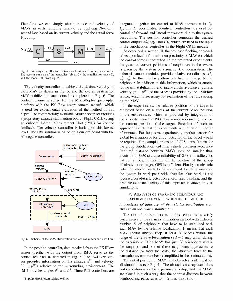
Fig. 5. Velocity controller for realization of outputs from the swarm rules.The system consists of the controller (block C), the stabilization unit (S),and the model (M) from eq. (5).
The velocity controller to achieve the desired velocity ofeach MAV is shown in Fig. 5, and the overall system forMAV stabilization and control is depicted in Fig. 6. Thecontrol scheme is suited for the MikroKopter quadcopterplatform with the PX4Flow smart camera sensor6, whichis used for experimental evaluation of the method in thispaper. The commercially available MikroKopter set includesa proprietary attitude stabilization board (Flight-CRTL) usingan onboard Inertial Measurement Unit (IMU) for controlfeedback. The velocity controller is built upon this lowestlevel. The HW solution is based on a custom board with theATmega µ-controller.
Fig. 6. Scheme of the MAV stabilization and control system and data flow.
In the position controller, data received from the PX4Flowsensor together with the output from IMU, serve as thecontrol feedback as depicted in Fig. 5. The PX4Flow sen-sor provides information on the altitude zW and velocity(xW ; yW ) relative to the surrounding environment. TheIMU provides angles θI and ψI . Three PID controllers are
6http://pixhawk.org/modules/px4flow
integrated together for control of MAV movement in Ix,Iy , and Iz coordinates. Identical controllers are used forcontrol of forward and lateral movement due to the systemdecoupling. The position controller computes the desiredcontrol outputs φID, ψI
D, and U ID, which are used as the input
in the stabilization controller in the Flight-CRTL module.As described in section III, the proposed flocking approach
relies upon local information on proximity of MAV for whichthe control force is computed. In the presented experiments,the guess of current positions of neighbours in the swarmis given by the system of visual relative localization. Theonboard camera modules provide relative coordinates, xIn,yIn, zIn, to the circular pattern attached on the particularneighbour. In addition to this information, which is crucialfor swarm stabilization and inter-vehicle avoidance, currentvelocity (xW , yW ) of the MAV is provided by the PX4Flowsensor, which is necessary for realization of the force actingon the MAV.
In the experiments, the relative position of the target isestimated based on a guess of the current MAV positionin the environment, which is provided by integration ofthe velocity from the PX4Flow sensor (odometry), and bythe current position of the target. Precision of such anapproach is sufficient for experiments with duration in orderof minutes. For long-term experiments, another sensor forglobal localization or for direct detection of the target wouldbe required. For example, precision of GPS is insufficient forthe group stabilization and inter-vehicle collision avoidance(required distance between MAVs may be smaller thanprecision of GPS and also reliability of GPS is insufficient),but for a rough estimation of the position of the grouprelatively to the target, GPS is sufficient. Finally, an obstacledetection sensor needs to be employed for deployment ofthe system in workspace with obstacles. Our work is notfocussed on obstacle detection and/or map building, and theobstacle avoidance ability of this approach is shown only insimulations.
V. ANALYSES OF SWARMING BEHAVIOUR ANDEXPERIMENTAL VERIFICATION OF THE METHOD
A. Analyses of influence of the relative localization con-straints on the swarm stabilization
The aim of the simulations in this section is to verifyperformance of the swarm stabilization method with differentnumber N of neighbours that have to be stabilized witheach MAV by the relative localization. It means that eachMAV should always keep at least N MAVs within therange of the relative localization (fd = 5 map units) duringthe experiment. If an MAV has just N neighbours withinthe range fd and one of these neighbours approaches tothe distance fd from the MAV, the attractive force to theparticular swarm member is amplified in these simulations.
The initial position of MAVs and obstacles is identical forall simulations (see Fig. 7). The obstacles are represented asvertical columns in the experimental setup, and the MAVsare placed in such a way that the shortest distance betweenneighbouring particles is D = 2 map units (mu).

Fig. 7. Initial setup of all experiments presented in this section.
The number of required neighbours N is set to zero in thefirst simulation (see snapshot in Fig. 8 and the graph of theshortest distances between MAVs in Fig. 9). Therefore, thestrong attractive force, which is integrated into the swarmingrules for keeping the localization linkage, is never applied inthis experiment. During the simulation, several MAVs areseparated from the swarm due to repulsive forces from theobstacles (their relative distance to the nearest neighbourexceeds the threshold fd = 5 mu).
Fig. 8. Snapshots from the simulation with number of neighbours N = 0.
Fig. 9. Relative distances to the nearest neighbour for each MAV of theswarm in the simulation shown in Fig. 8.
The number of neighbours is set as N = 1 in the secondsimulation (see snapshots in Fig. 10 and the graph of theshortest distances to the nearest neighbour for each MAV inFig. 11). If the nearest neighbour of an MAV approachesto the relative distance fd = 5 mu, the attractive forcepushes this MAV to the direction of this neighbour, whichalso helps to keep integrity of the MAV swarm (comparegraphs 8 and 10). No MAV becomes more distant from its
nearest neighbour than the given threshold 5 mu during theexperiment, which ensures required reliability of the visualrelative localization.
Fig. 10. Snapshots from the simulation with number of neighbours N = 1.
Fig. 11. Relative distances to the nearest neighbour for each MAV of theswarm in the simulation shown in Fig. 10.
In the third simulation, two neighbours are required in thelocalization distance 5 mu for each MAV (N = 2). The graphof the shortest distances to the second nearest neighbour isshown in Fig. 12. The requirement on connectivity with atleast two neighbours for each MAV is satisfied during the ex-periment. Such stronger requirement again increases integrityof the swarm and also robustness of swarm stability. In caseof temporary drop-out of the onboard relative localizationwith one of the neighbours, the MAV can be connected withrest of the team through the second vehicle in its sensoryrange.
Fig. 12. Relative distances to the second nearest neighbour for each MAVof the swarm in the simulation with number of neighbours N = 2.
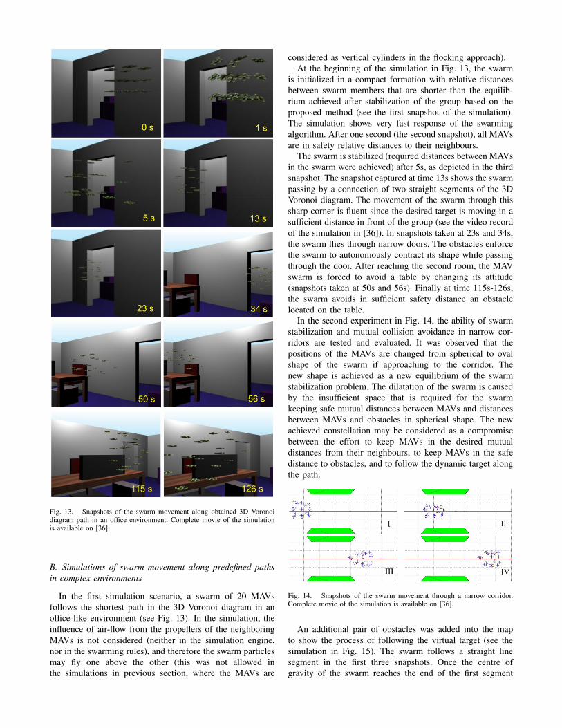
Fig. 13. Snapshots of the swarm movement along obtained 3D Voronoidiagram path in an office environment. Complete movie of the simulationis available on [36].
B. Simulations of swarm movement along predefined pathsin complex environments
In the first simulation scenario, a swarm of 20 MAVsfollows the shortest path in the 3D Voronoi diagram in anoffice-like environment (see Fig. 13). In the simulation, theinfluence of air-flow from the propellers of the neighboringMAVs is not considered (neither in the simulation engine,nor in the swarming rules), and therefore the swarm particlesmay fly one above the other (this was not allowed inthe simulations in previous section, where the MAVs are
considered as vertical cylinders in the flocking approach).At the beginning of the simulation in Fig. 13, the swarm
is initialized in a compact formation with relative distancesbetween swarm members that are shorter than the equilib-rium achieved after stabilization of the group based on theproposed method (see the first snapshot of the simulation).The simulation shows very fast response of the swarmingalgorithm. After one second (the second snapshot), all MAVsare in safety relative distances to their neighbours.
The swarm is stabilized (required distances between MAVsin the swarm were achieved) after 5s, as depicted in the thirdsnapshot. The snapshot captured at time 13s shows the swarmpassing by a connection of two straight segments of the 3DVoronoi diagram. The movement of the swarm through thissharp corner is fluent since the desired target is moving in asufficient distance in front of the group (see the video recordof the simulation in [36]). In snapshots taken at 23s and 34s,the swarm flies through narrow doors. The obstacles enforcethe swarm to autonomously contract its shape while passingthrough the door. After reaching the second room, the MAVswarm is forced to avoid a table by changing its attitude(snapshots taken at 50s and 56s). Finally at time 115s-126s,the swarm avoids in sufficient safety distance an obstaclelocated on the table.
In the second experiment in Fig. 14, the ability of swarmstabilization and mutual collision avoidance in narrow cor-ridors are tested and evaluated. It was observed that thepositions of the MAVs are changed from spherical to ovalshape of the swarm if approaching to the corridor. Thenew shape is achieved as a new equilibrium of the swarmstabilization problem. The dilatation of the swarm is causedby the insufficient space that is required for the swarmkeeping safe mutual distances between MAVs and distancesbetween MAVs and obstacles in spherical shape. The newachieved constellation may be considered as a compromisebetween the effort to keep MAVs in the desired mutualdistances from their neighbours, to keep MAVs in the safedistance to obstacles, and to follow the dynamic target alongthe path.
Fig. 14. Snapshots of the swarm movement through a narrow corridor.Complete movie of the simulation is available on [36].
An additional pair of obstacles was added into the mapto show the process of following the virtual target (see thesimulation in Fig. 15). The swarm follows a straight linesegment in the first three snapshots. Once the centre ofgravity of the swarm reaches the end of the first segment

(snapshot III in Fig. 15), the position of the virtual target issuddenly changed to enable the swarm to follow the secondline segment (snapshot IV). Once the third line segment isreached, the position of the virtual target again suddenlydrops into the direction of this segment.
Fig. 15. Simulation of the swarm movement in a narrow corridor along apath composed from three line segments. Complete movie of the simulationis available on [36].
C. Experiments with quad-rotor MAVs
The possibility of stabilization of MAV group usingthe onboard relative localization system has been testedin numerous experiments with quadrotor helicopters in in-door and outdoor environment (see Fig. 16-17 for snap-shots and http://mrs.felk.cvut.cz/research/swarm-robotics for actual movies of the system).
In experiments, MAVs follow a given path, where the posi-tion estimation of the group relatively to the path is obtainedby integration of MAV velocity from the PX4Flow sensor.In short-term experiments, position error of this methoddoes not influence performance of the system. Moreover,the error would be reduced by coupling of team membersvia the mutual localization in large swarms. For long-termexperiments, an onboard system providing information onglobal position of the group in the environment would benecessary (see e.g. [37], [38] for proper methods designedwithin our team).
In the indoor experiment, the MAV in the middle ofthe group is stabilized using the data from the PX4Flowsensor, while the outer MAVs are stabilized in a desiredrelative position to the middle MAV using onboard relativelocalization in control feedback. Sensor data processing andcontrol commands are all computed onboard of MAVs.
The outdoor experiment is conducted in outdoor environ-ment to show robustness of the system in changing lightand windy conditions. Moreover, the grass surface is achallenging environment for the PX4Flow sensor. Due tothe grass blowing in the wind, an additional noise is addedinto the measurement, which increases the position error. In
Fig. 16. Experiment with 3 MAVs relatively stabilized using onboard visuallocalization in indoor environment.
the experiment, MAVs repeatedly follow the path and thenreturn to the initial position. Again, the MAVs strictly relyon onboard sensors, and no communication is required forgroup stabilization.
Fig. 17. Experiment with 2 MAVs following a preplanned path in outdoorenvironment. Video record of the experiment is available on [36].
VI. CONCLUSION
A bio-inspired swarm stabilization approach for controland navigation of large teams of MAVs along a given pathwas presented in this paper. The method respects restrictionsof swarm robotics in terms of missing communication amongvehicles, decentralized control rules, anonymity of swarmparticles, and onboard sensors that provide information onlocal proximity of MAVs. The swarm behaviour proposedin this paper is designed for MAV platforms equippedwith the onboard visual relative localization of neighbouringteam members. This sensor is very similar to sense organsof animals that perform flocking behaviour in nature, andit provides possibility of flying in very compact groups,for which precision and reliability of commonly availablelocalization systems (such as GPG) is insufficient.
VII. ACKNOWLEDGEMENTS
This work was realized with help of Tomas Sekan-ina and Jan Vales. An extended description of some ex-perimental results presented in this paper is available intheir thesis. The work was supported by CTU grant no.SGS15/157/OHK3/2T/13 and by GACR no. P10312/P756.

REFERENCES
[1] W. Teacy, J. Nie, S. McClean, and G. Parr, “Maintaining connectivityin uav swarm sensing,” in IEEE GLOBECOM Workshops, 2010.
[2] T. Schmickl and K. Crailsheim, “Trophallaxis within a robotic swarm:bio-inspired communication among robots in a swarm,” AutonomousRobots, vol. 25, pp. 171–188, 2008.
[3] A. Purohit, P. Zhang, B. Sadler, and S. Carpin, “Deployment ofswarms of micro-aerial vehicles: From theory to practice,” in IEEEInternational Conference on Robotics and Automation (ICRA), 2014.
[4] S. Berman, A. Halasz, M. Hsieh, and V. Kumar, “Optimized stochasticpolicies for task allocation in swarms of robots,” IEEE Transactionson Robotics, vol. 25, no. 4, pp. 927 –937, 2009.
[5] W. Liu, A. Winfield, J. Sa, J. Chen, and L. Dou, “Strategies for energyoptimisation in a swarm of foraging robots,” in Swarm Robotics, 2007,vol. 4433, pp. 14–26.
[6] V. Vonasek, S. Neumann, L. Winkler, K. Kosnar, H. Woern, andL. Preucil, “Task-Driven Evolution of Modular Self-ReconfigurableRobots,” in From Animals to Animats 13, vol. 8575, 2014, pp. 240–249.
[7] R. K. Sharma and D. Ghose, “Collision avoidance between uav clustersusing swarm intelligence techniques,” Intern. J. Syst. Sci., vol. 40, pp.521–538, May 2009.
[8] M. Kumar, D. Garg, and V. Kumar, “Segregation of heterogeneousunits in a swarm of robotic agents,” IEEE Transactions on AutomaticControl, vol. 55, no. 3, pp. 743 –748, 2010.
[9] M. Hess, M. Saska, and K. Schilling, “Application of CoordinatedMulti-Vehicle Formations for Snow Shoveling on Airports,” IntelligentService Robotics, vol. 2, no. 4, pp. 205–217, 2009.
[10] V. Vonasek, O. Penc, K. Kosnar, and L. Preucil, “Optimization of Mo-tion Primitives for High-Level Motion Planning of Modular Robots,”in CLAWAR 2014: 17th International Conference on Climbing andWalking Robots, 2014, pp. 109–116.
[11] V. Vonasek, M. Saska, L. Winkler, and L. Preucil, “High-level motionplanning for cpg-driven modular robots, robotics and autonomoussystems,” Robotics and Autonomous Systems, vol. 68, p. 116128, 2015.
[12] V. Vonasek, M. Saska, K. Kosnar, and L. Preucil, “Global MotionPlanning for Modular Robots with Local Motion Primitives,” inICRA2013: Proceedings of 2013 IEEE International Conference onRobotics and Automation, 2013.
[13] V. Vonasek, M. Saska, and L. Preucil, “Motion Planning for a CableDriven Parallel Multiple Manipulator Emulating a Swarm of MAVs,”in ROBOT MOTION AND CONTROL 2013. IEEE Robotics andAutomation Society, 2013, pp. 13–18.
[14] M. Hess, M. Saska, and K. Schiling, “Formation Driving UsingParticle Swarm Optimization and Reactive Obstacle Avoidance,” inMultivehicle Systems, 2006, pp. 32–37.
[15] M. Saska, V. Vonasek, and L. Preucil, “Roads Sweeping by UnmannedMulti-vehicle Formations,” in ICRA2011: Proceedings of 2011 IEEEInternational Conference on Robotics and Automation, 2011.
[16] M. Basiri, F. Schill, D. Floreano, and P. Lima, “Audio-based localiza-tion for swarms of micro air vehicles,” in Robotics and Automation(ICRA), 2014 IEEE International Conference on, 2014.
[17] A. Winfield, W. Liu, J. Nembrini, and A. Martinoli, “Modelling awireless connected swarm of mobile robots,” Swarm Intelligence,vol. 2, pp. 241–266, 2008.
[18] H. Hamann and H. Worn, “A framework of spacetime continuousmodels for algorithm design in swarm robotics,” Swarm Intelligence,vol. 2, pp. 209–239, 2008.
[19] L. Weng, Q. Liu, M. Xia, and Y. Song, “Immune network-based swarmintelligence and its application to unmanned aerial vehicle (uav) swarmcoordination,” Neurocomputing, vol. 125, pp. 134 – 141, 2014.
[20] M. Kloetzer and C. Belta, “Temporal logic planning and control ofrobotic swarms by hierarchical abstractions,” IEEE Transactions onRobotics, vol. 23, no. 2, pp. 320 –330, 2007.
[21] C. C. Cheah, S. P. Hou, and J. J. E. Slotine, “Region-based shapecontrol for a swarm of robots,” Automatica, vol. 45, no. 10, pp. 2406– 2411, 2009.
[22] D. J. Bennet and C. R. McInnes, “Verifiable control of a swarm ofunmanned aerial vehicles,” Journal of Aerospace Engineering, vol.223, no. 7, pp. 939–953, 2009.
[23] L. Barnes, R. Garcia, M. Fields, and K. Valavanis, “Swarm formationcontrol utilizing ground and aerial unmanned systems,” in IEEE/RSJInternational Conference on Intelligent Robots and Systems., 2008.
[24] V. Trianni, Evolutionary Swarm Robotics. Springer, 2008.
[25] A. Christensen, R. O’Grady, and M. Dorigo, “From fireflies tofault-tolerant swarms of robots,” IEEE Transactions on EvolutionaryComputation, vol. 13, no. 4, pp. 754 –766, 2009.
[26] D. Gu and H. Hu, “Using fuzzy logic to design separation function inflocking algorithms,” Fuzzy Systems, IEEE Transactions on, vol. 16,no. 4, pp. 826–838, 2008.
[27] H. Min and Z. Wang, “Design and analysis of group escape behaviorfor distributed autonomous mobile robots,” in 2011 IEEE InternationalConference on Robotics and Automation (ICRA), 2011.
[28] R. Olfati-Saber, “Flocking for multi-agent dynamic systems: algo-rithms and theory,” IEEE Transactions on Automatic Control, vol. 51,no. 3, pp. 401–420, 2006.
[29] M. Saska, J. Vakula, and L. Preucil, “Swarms of Micro Aerial Vehi-cles Stabilized Under a Visual Relative Localization,” in ICRA2014:Proceedings of 2014 IEEE International Conference on Robotics andAutomation. IEEE, 2014.
[30] M. Saska, Z. Kasl, and L. Preucil, “Motion Planning and Control ofFormations of Micro Aerial Vehicles,” in Proceedings of The 19thWorld Congress of the International Federation of Automatic Control,Pretoria, 2014.
[31] M. Saska, T. Krajnik, V. Vonasek, P. Vanek, and L. Preucil, “Nav-igation, Localization and Stabilization of Formations of UnmannedAerial and Ground Vehicles,” in Proceedings of 2013 InternationalConference on Unmanned Aircraft Systems, 2013.
[32] T. Krajnk, M. Nitsche, J. Faigl, P. Vank, M. Saska, L. Peuil, T. Duckett,and M. Mejail, “A practical multirobot localization system,” Journalof Intelligent & Robotic Systems, vol. 76, no. 3-4, pp. 539–562, 2014.
[33] M. Saska, T. Krajnk, V. Vonsek, Z. Kasl, V. Spurn, and L. Peuil, “Fault-tolerant formation driving mechanism designed for heterogeneousmavs-ugvs groups,” Journal of Intelligent & Robotic Systems, vol. 73,no. 1-4, pp. 603–622, 2014.
[34] J. Faigl, T. Krajnık, , J. Chudoba, L. Preucil, and M. Saska, “Low-costembedded system for relative localization in robotic swarms,” in Proc.of IEEE International Conference on Robotics and Automation, 2013.
[35] C. Reynolds, “Flocks, herds and schools: A distributed behavioralmodel.” in SIGGRAPH ’87: Proceedings of the 14th annual conferenceon Computer graphics and interactive techniques., 1987.
[36] Movie, “Movie of experiments and simulations of the swarmingbehaviour [online]. http://mrs.felk.cvut.cz/data/swarmicuas/ [cit. 2015-2-14],” 2015.
[37] J. Chudoba, M. Saska, T. Baca, and L. Preucil, “Localization andstabilization of micro aerial vehicles based on visual features tracking,”in Proceedings of 2014 2014 International Conference on UnmannedAircraft Systems (ICUAS), 2014.
[38] M. Saska, T. Krajnik, J. Faigl, V. Vonasek, and L. Preucil, “Low CostMAV Platform AR-Drone in Experimental Verifications of Methodsfor Vision Based Autonomous Navigation,” in Proceedings of 2012IEEE/RSJ International Conference on Intelligent Robots and Systems,2012.