max-on software user’s manual · proficy machine edition development environment using proficy...
TRANSCRIPT
GE Intelligent Platforms
Programmable Control Products
Max-ON Software User’s Manual
for the 90-30 Platform
GFK-2053C
July 2010
GFL-002
Warnings, Cautions, and Notes
as Used in this Publication
Warning
Warning notices are used in this publication to emphasize that hazardous voltages, currents,
temperatures, or other conditions that could cause personal injury exist in this equipment or may
be associated with its use.
In situations where inattention could cause either personal injury or damage to equipment, a
Warning notice is used.
Caution
Caution notices are used where equipment might be damaged if care is not taken.
Note: Notes merely call attention to information that is especially significant to understanding
and operating the equipment.
This document is based on information available at the time of its publication. While efforts have
been made to be accurate, the information contained herein does not purport to cover all details
or variations in hardware or software, nor to provide for every possible contingency in connection
with installation, operation, or maintenance. Features may be described herein which are not
present in all hardware and software systems. GE Intelligent Platforms assumes no obligation of
notice to holders of this document with respect to changes subsequently made.
GE Intelligent Platforms makes no representation or warranty, expressed, implied, or statutory with
respect to, and assumes no responsibility for the accuracy, completeness, sufficiency, or usefulness
of the information contained herein. No warranties of merchantability or fitness for purpose
shall apply.
* indicates a trademark of GE Intelligent Platforms, Inc. and/or its affiliates. All other trademarks
are the property of their respective owners.
©Copyright 2010 GE Intelligent Platforms, Inc.
All Rights Reserved
Support
Technical Support
If you purchased this product through an Authorized Channel Partner, please contact them directly.
General Contact Information
Online Technical Support and GlobalCare: www.ge-ip.com/support
Additional information: www.ge-ip.com
Technical Support
If you have technical problems that cannot be resolved with the information in this guide, please
contact us by telephone or email, or on the web at www.ge-ip.com/support
Americas
Online Technical Support: www.ge-ip.com/support
Phone: 1-800-433-2682
International Americas Direct Dial: 1-780-420-2010
Technical Support Email: [email protected]
Customer Care Email: [email protected]
Primary language of support: English
Europe, the Middle East, and Africa
Online Technical Support: www.ge-ip.com/support
Phone: +800-1-433-2682
Direct Dial: +352-26-722-780 (if toll free 800 option is unavailable or dialing from a mobile telephone)
Technical Support Email: [email protected]
Customer Care Email: [email protected]
Primary languages of support: English, French, German, Italian, Czech, Spanish
Asia Pacific
Online Technical Support: www.ge-ip.com/support
Phone: +86-400-820-8208
+86-21-3217-4826 (India, Indonesia, and Pakistan)
Technical Support Email: [email protected] (China)
[email protected] (Japan)
[email protected] (remaining Asia customers)
Customer Care Email: [email protected]
[email protected] (China)

Contents
GFK-2053C iii
Introduction .................................................................................................................... 1
Welcome ............................................................................................................................... 1
Installing Max-ON Software .................................................................................................. 3
System Requirements .................................................................................................. 3
To Install Max-ON Software ......................................................................................... 3
Uninstalling Max-ON Software ..................................................................................... 4
Max-ON Component Installation .................................................................................. 5
Technical Support ............................................................................................................... 10
GE IP Global Care Web Site ...................................................................................... 10
North America ............................................................................................................ 10
Asia ............................................................................................................................ 10
Europe, Middle East, and Africa ................................................................................ 10
South America ............................................................................................................ 10
System Overview ........................................................................................................... 1
Architecture .................................................................................................................. 1
Product Selections ....................................................................................................... 1
Software Components .................................................................................................. 5
Hot Standby Redundancy Operation ........................................................................... 6
Failover Time ............................................................................................................... 7
Synchronized Data Transfers....................................................................................... 7
I/O Bus Topologies ....................................................................................................... 9
Selecting the I/O ......................................................................................................... 10
Product Authorization ................................................................................................. 11
Building a Max-ON Hot Standby Application ............................................................... 1
Max-ON Project .................................................................................................................... 1
Project Workflow ................................................................................................................... 2
The Max-ON Configuration Utility ................................................................................. 1
Max-ON Projects ................................................................................................................... 1
Working with the Max-ON Configuration Utility .................................................................... 6
Working with Racks ...................................................................................................... 6
Working with Modules .................................................................................................. 8
Defining Ethernet LANs .............................................................................................. 24
Synchronized Data ..................................................................................................... 25
Project Information ..................................................................................................... 28
System Options .......................................................................................................... 32
User Defined Alarms .................................................................................................. 33
Programming Considerations ....................................................................................... 1
Advanced Topics ........................................................................................................ 17
Configuring the Hot Backup CPUs ............................................................................... 1
Configuring PLC A ....................................................................................................... 3
Contents
iv Max-ON Software User’s Manual–July 2010 GFK-2053C
Configuring PLC B ..................................................................................................... 11
Configuring the I/O Devices .......................................................................................... 1
Configuring the Genius I/O Devices ............................................................................. 1
Product Authorization ................................................................................................... 1
Generating the Key Code............................................................................................. 1
Create the Authorization Request Form ...................................................................... 1
Obtain the Authorization Codes ................................................................................... 3
Enter the Authorization Codes ..................................................................................... 3
Update the C-Block ...................................................................................................... 4
Store the Target ........................................................................................................... 5
Verifying the Authorization Codes ................................................................................ 5
Restarting CPU A ......................................................................................................... 7
Updating an Existing Application ................................................................................. 1
Overview ...................................................................................................................... 1
Updating an Existing Max-ON Application ............................................................................ 3
Backup the Application ................................................................................................. 3
Update the Max-ON Drivers ......................................................................................... 5
Diagnostic Tools ............................................................................................................ 1
Step 2 – Configure Ethernet Connections to the PLCs ............................................... 3
Step 3 – Use the Max-ON Diagnostic Tool .................................................................. 5
System Status .............................................................................................................. 7
Alarms .......................................................................................................................... 8
Ethernet Information ...................................................................................................... 1
Ethernet Hardware ....................................................................................................... 1
PLC Sweep Mode ........................................................................................................ 1
Frequently Asked Questions ........................................................................................ 1
GFK-2053C 1-1
Introduction
Welcome
Thank you for choosing Max-ON software and GE Intelligent Platform controllers to implement
your critical control project.
Max-ON software consists of several software components, some of which execute in a pair
of Hot-Standby PLCs, and some of which execute upon your programming workstation.
The controller-based software consists of a set of application blocks that perform the
Redundancy portion of the Hot Standby application. These application blocks are provided as
part of a Proficy™ Machine Edition Project that is the starting point of your redundant
automation application. Using GE IP’s Proficy Logic Developer PLC programming software,
you add your application logic to this project, and then store the overall project to each of the
Hot Standby controllers.
The Max-ON Configuration Utility, which is launched from the Logic Developer PLC Project,
provides a utility to allow the control system designer to customize the functionality of the
redundant system.
A Proficy View Project is also provided to monitor the status of the Redundant System and to
display diagnostic information.
Chapter
1
1-2 Max-ON™ Software – July 2010 GFK-2053C
1
With the Max-ON LD Project, you can:
• Create a Hot Standby system that operates using a combination of GE IP Genius™
I/O, Field Control™, Series 90™-30 remote Genius drops, and Genius VersaMax™
I/O, as well as Series 90-30 and PACSystems Ethernet NIUs.
• Synchronize application data using an Ethernet LAN.
With the Max-ON Configuration Utility software, you can:
• View and modify the parameters of the Hot Standby Redundancy system:
� Redundant System Parameters
� Synchronization Data Groups
� Synchronization Network Interface Parameters
� Genius I/O Bus definitions
With the Max-ON View Project, you can:
• Establish a communication link to the Hot Standby CPUs to:
� Monitor system-level alarms in real-time
� Monitor performance characteristics in real-time
� Display information about the Redundant system: Max-ON driver version, CPU
modules
GFK-2053C Chapter 1 Introduction 1-3
1
Installing Max-ON Software
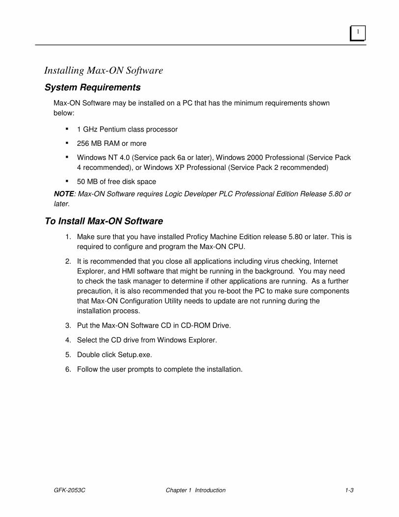
System Requirements
Max-ON Software may be installed on a PC that has the minimum requirements shown
below:
▪ 1 GHz Pentium class processor
▪ 256 MB RAM or more
▪ Windows NT 4.0 (Service pack 6a or later), Windows 2000 Professional (Service Pack
4 recommended), or Windows XP Professional (Service Pack 2 recommended)
▪ 50 MB of free disk space
NOTE: Max-ON Software requires Logic Developer PLC Professional Edition Release 5.80 or
later.
To Install Max-ON Software
1. Make sure that you have installed Proficy Machine Edition release 5.80 or later. This is
required to configure and program the Max-ON CPU.
2. It is recommended that you close all applications including virus checking, Internet
Explorer, and HMI software that might be running in the background. You may need
to check the task manager to determine if other applications are running. As a further
precaution, it is also recommended that you re-boot the PC to make sure components
that Max-ON Configuration Utility needs to update are not running during the
installation process.
3. Put the Max-ON Software CD in CD-ROM Drive.
4. Select the CD drive from Windows Explorer.
5. Double click Setup.exe.
6. Follow the user prompts to complete the installation.

1-4 Max-ON™ Software – July 2010 GFK-2053C
1
Uninstalling Max-ON Software
Max-ON Software can be uninstalled only from the computer upon which it is installed. It
cannot be uninstalled over a network. You can uninstall Max-ON Software from the
Add/Remove Programs option on the Windows Control Panel or from the Windows Start
Menu.
If the computer has other GE IP software products installed, Max-ON Software can be
uninstalled without removing any files needed by those applications. To uninstall Max-ON
Software, do the following:
1. Choose Uninstall from the Start Menu or the Control Panel.
2. A dialog box appears asking if you are sure you want to uninstall.
3. Confirm the Uninstall.
▪ All files relating to Max-ON Software will be removed from the hard drive. Any files
used by both Max-ON Configuration Utility and another application will be left on the
system.
▪ All registry entries relating to Max-ON Software will be removed from the systems
registry.
▪ Icons for Max-ON Software will be removed from the Start Menu.
▪ Any data you created (for example, Project that you have created) will be left on the
system.
Note: You may also uninstall Max-ON Software by choosing Add/Remove Programs from
the Control Panel, then selecting Max-ON Tools.
GFK-2053C Chapter 1 Introduction 1-5
1
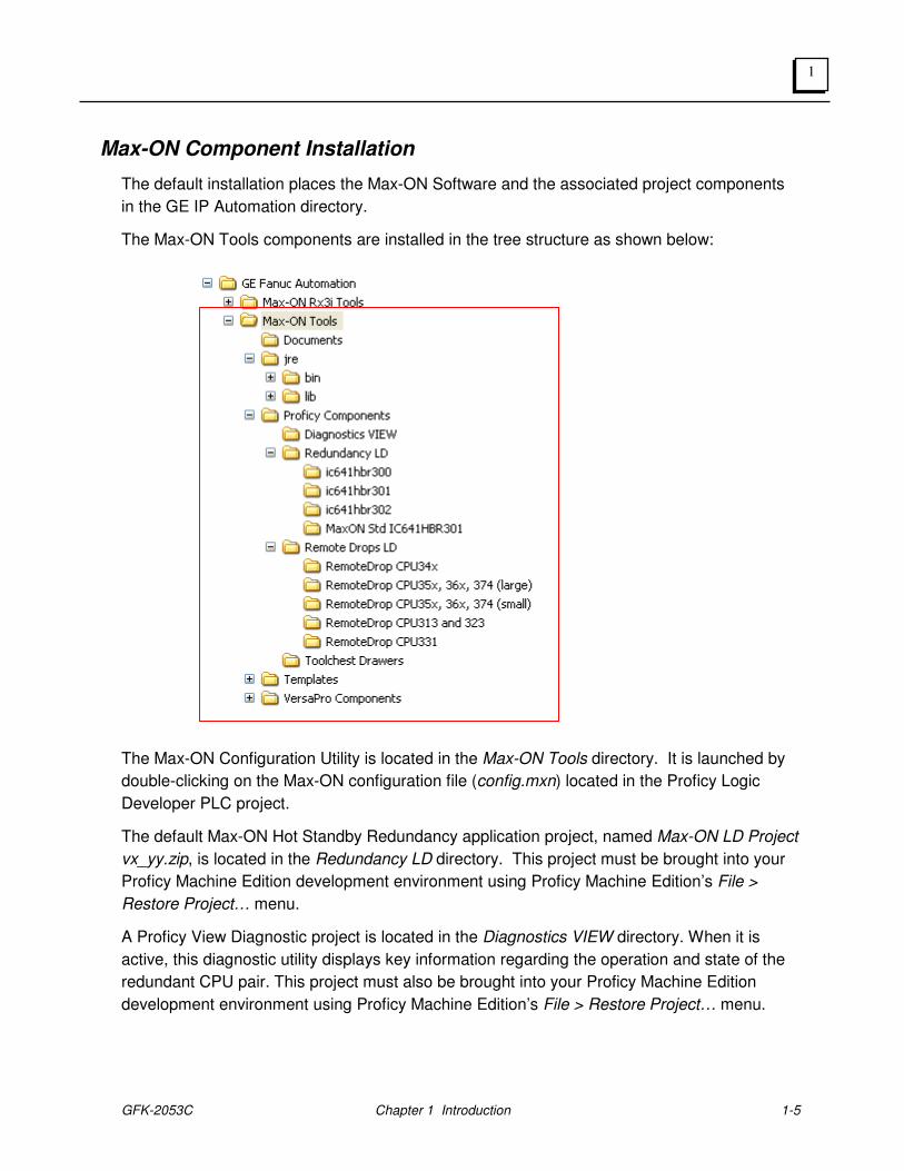
Max-ON Component Installation
The default installation places the Max-ON Software and the associated project components
in the GE IP Automation directory.
The Max-ON Tools components are installed in the tree structure as shown below:
The Max-ON Configuration Utility is located in the Max-ON Tools directory. It is launched by
double-clicking on the Max-ON configuration file (config.mxn) located in the Proficy Logic
Developer PLC project.
The default Max-ON Hot Standby Redundancy application project, named Max-ON LD Project
vx_yy.zip, is located in the Redundancy LD directory. This project must be brought into your
Proficy Machine Edition development environment using Proficy Machine Edition’s File >
Restore Project… menu.
A Proficy View Diagnostic project is located in the Diagnostics VIEW directory. When it is
active, this diagnostic utility displays key information regarding the operation and state of the
redundant CPU pair. This project must also be brought into your Proficy Machine Edition
development environment using Proficy Machine Edition’s File > Restore Project… menu.
1-6 Max-ON™ Software – July 2010 GFK-2053C
1
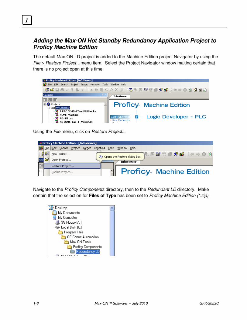
Adding the Max-ON Hot Standby Redundancy Application Project to Proficy Machine Edition
The default Max-ON LD project is added to the Machine Edition project Navigator by using the
File > Restore Project…menu item. Select the Project Navigator window making certain that
there is no project open at this time.
Using the File menu, click on Restore Project...
Navigate to the Proficy Components directory, then to the Redundant LD directory. Make
certain that the selection for Files of Type has been set to Proficy Machine Edition (*.zip).
GFK-2053C Chapter 1 Introduction 1-7
1
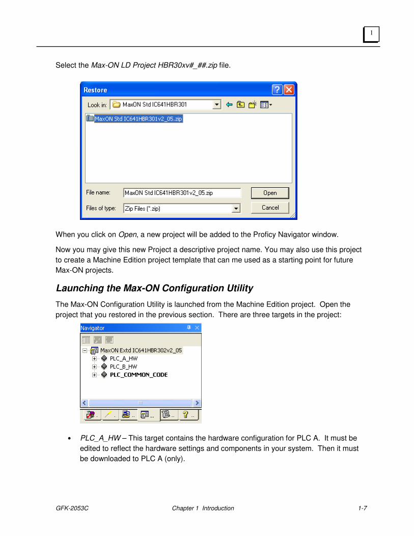
Select the Max-ON LD Project HBR30xv#_##.zip file.
When you click on Open, a new project will be added to the Proficy Navigator window.
Now you may give this new Project a descriptive project name. You may also use this project
to create a Machine Edition project template that can me used as a starting point for future
Max-ON projects.
Launching the Max-ON Configuration Utility
The Max-ON Configuration Utility is launched from the Machine Edition project. Open the
project that you restored in the previous section. There are three targets in the project:
• PLC_A_HW – This target contains the hardware configuration for PLC A. It must be
edited to reflect the hardware settings and components in your system. Then it must
be downloaded to PLC A (only).
1-8 Max-ON™ Software – July 2010 GFK-2053C
1
• PLC_B_HW – This target contains the hardware configuration for PLC B. It must be
edited to reflect the hardware settings and components in your system. It will be very
similar to PLC A hardware configuration, except for certain items such IP addresses,
Genius bus controller settings, etc. In a similar fashion, this configuration must be
downloaded to PLC B (only).
• PLC_COMMON_CODE – This target contains the core logic for the Max-ON
redundancy application. You must add your application logic starting in the rung that
follows the call to the core Max-ON logic (hbr_000). The logic from this target will be
downloaded to both PLC A and PLC B. Note that the download consists of the PLC
Logic Only, the Hardware Configuration option must be unchecked.
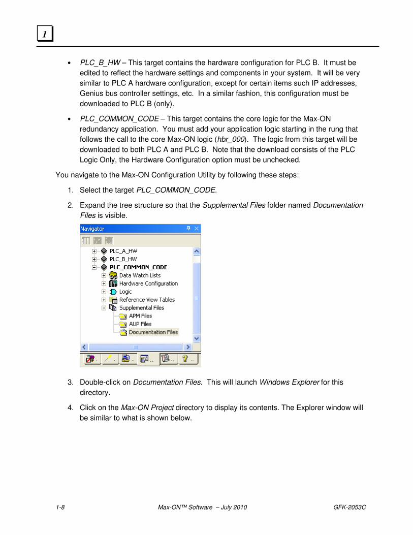
You navigate to the Max-ON Configuration Utility by following these steps:
1. Select the target PLC_COMMON_CODE.
2. Expand the tree structure so that the Supplemental Files folder named Documentation
Files is visible.
3. Double-click on Documentation Files. This will launch Windows Explorer for this
directory.
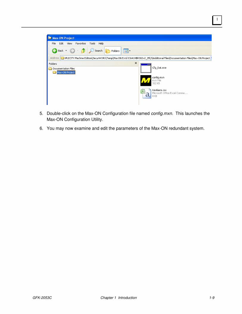
4. Click on the Max-ON Project directory to display its contents. The Explorer window will
be similar to what is shown below.
GFK-2053C Chapter 1 Introduction 1-9
1
5. Double-click on the Max-ON Configuration file named config.mxn. This launches the
Max-ON Configuration Utility.
6. You may now examine and edit the parameters of the Max-ON redundant system.

1-10 Max-ON™ Software – July 2010 GFK-2053C
1
Technical Support
Technical Support is available at no charge for 90 days after purchase. A support agreement
can be purchased from your local GE IP distributor if extended support is required.
If problems arise that can’t be solved using the information in your product manual, online
Help system, Proficy GlobalCare knowledge base, or the GE IP Technical Advisor knowledge
base, contact us by telephone, fax, or mail. When contacting us, call from a telephone near
your computer and have your Machine Edition software running. Have the following
information handy to help us assist you as quickly as possible:
• Proficy Machine Edition software installation serial number, the Proficy Machine
Edition software Product name, and version number from the Help >About dialog box.
• The brand and model of any hardware in your system.
• Operating system and version number.
• The steps you performed prior to the problem occurring.
GE IP Global Care Web Site
The GE IP Global Care Web Site offers product, service, and support information for GE IP
hardware and software products. The Global Care web site is located at:
http://www.ge-IP.com/
Visit this site for the latest up-to-date technical information.
North America
Support Hotline: 1-800-433-2682 780-420-2010 (if toll free 800 option is unavailable) Fax: (780) 420-2049
Internet: http://www.ge-IP.com/ Email: http://support.ge-ip.com Comments about our manuals and help: [email protected] Mailing Address: GE IP, 2700 Oxford Tower, 10235 - 101 St., Edmonton, AB, Canada, T5J 3G1
Asia
Japan: Telephone 81-3-5405-7555; fax 81-3-5405-7550 China: Telephone 0086-21-32224555 x200; fax 0086-21-62793066
Europe, Middle East, and Africa
Europe, Middle East, and Africa: + 1-800-433-2682 or + 1 780-401-7717
South America
Telephone: +58 (261) 760 2862 Fax: +58 (261) 765 0909 Internet: http://www.ge-IP.com/ (visit our Portuguese web site at http://www.ge-IP.com.br/) E-Mail: [email protected] Mailing Address: GE IP Latin America, Calle 120 con Av. 17, Los Haticos -GE Turbimeca Maracaibo, Venezuela

GFK-2053C Chapter 1 Introduction 1-11
1

1-12 Max-ON™ Software – July 2010 GFK-2053C
1
GFK-2053C 2-1
System Overview
Architecture
A Max-ON Series 90-30 Hot Standby Redundancy system consists of two Series 90-30 Controllers, at least one Genius bus used to transfer key system data, and an I/O system. The I/O devices may share the Genius bus that is used to transfer the system data.
Max-ON for the 90-30 PLCs is available in three different models. The models are distinguished from each other by the number of I/Os than may be serviced, the number of Genius I/O LANs supported, the quantity of synchronized data that may be transferred, and the use of one or more optional Ethernet LAN(s) for application data transfers.
The I/O system may be implemented using a combination of Genius I/O, Field Control I/O, VersaMax I/O, or Remote I/O drops based upon Series 90-30 I/O.
Product Selections
Max-ON is available in three different models. By offering scaleable solutions, you may chose the product that matches your I/O requirements as well as data synchronization performance. (For high performance systems, you should investigate the GE IP PACSystems family of Hot-Standby processors.)
Chapter
2
2-2 Max-ON™ Software User's Manual – July 2010 GFK-2053C
2
Max-ON Lite
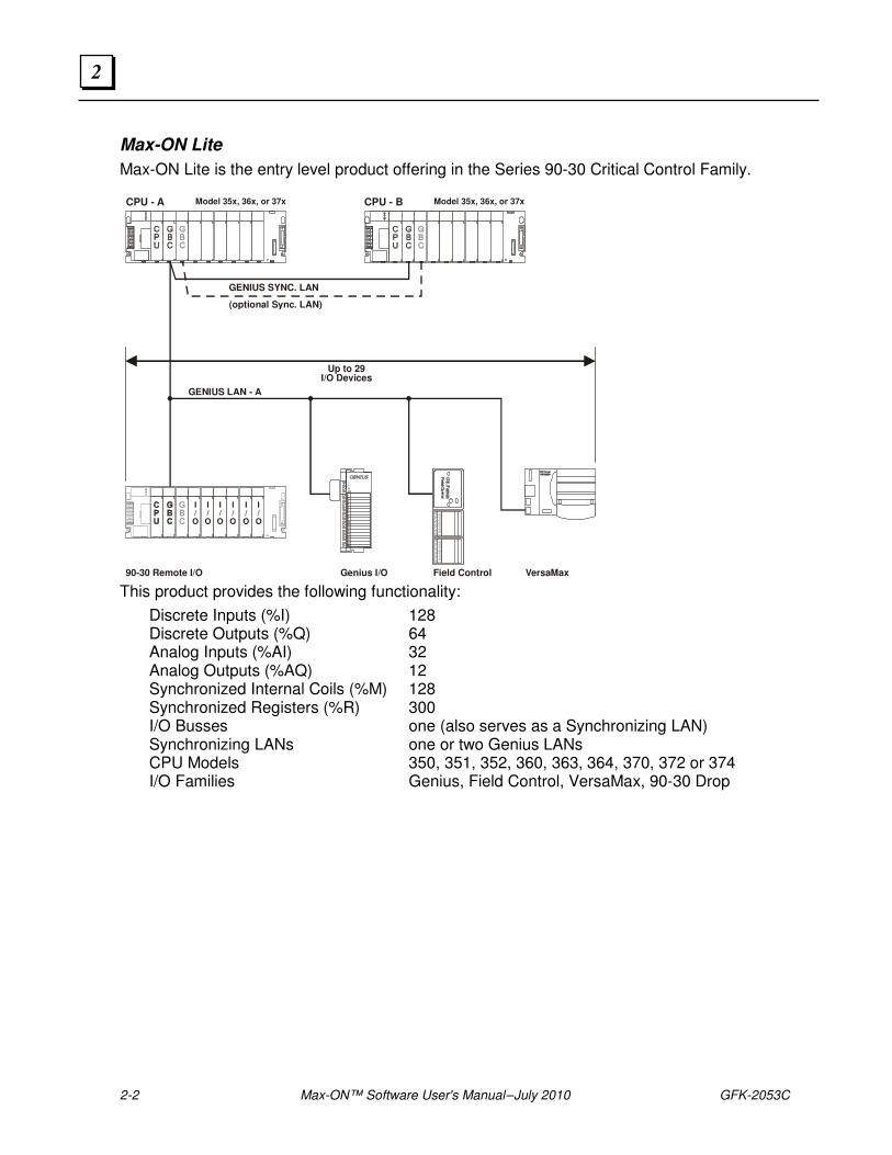
Max-ON Lite is the entry level product offering in the Series 90-30 Critical Control Family.
This product provides the following functionality:
Discrete Inputs (%I) 128 Discrete Outputs (%Q) 64 Analog Inputs (%AI) 32 Analog Outputs (%AQ) 12 Synchronized Internal Coils (%M) 128 Synchronized Registers (%R) 300 I/O Busses one (also serves as a Synchronizing LAN) Synchronizing LANs one or two Genius LANs CPU Models 350, 351, 352, 360, 363, 364, 370, 372 or 374 I/O Families Genius, Field Control, VersaMax, 90-30 Drop
CPU - A Model 35x, 36x, or 37xModel 35x, 36x, or 37x CPU - B
90-30 Remote I/O Genius I/O Field Control VersaMax
GENIUS LAN - A
Up to 29I/O Devices
I/O
I/O
I/O
I/O
I/O
I/O
(optional Sync. LAN)
GENIUS SYNC. LAN
GFK-2053C Chapter 2 System Overview 2-3
2
Max-ON Standard
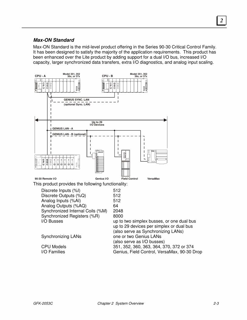
Max-ON Standard is the mid-level product offering in the Series 90-30 Critical Control Family. It has been designed to satisfy the majority of the application requirements. This product has been enhanced over the Lite product by adding support for a dual I/O bus, increased I/O capacity, larger synchronized data transfers, extra I/O diagnostics, and analog input scaling.
This product provides the following functionality:
Discrete Inputs (%I) 512 Discrete Outputs (%Q) 512 Analog Inputs (%AI) 512 Analog Outputs (%AQ) 64 Synchronized Internal Coils (%M) 2048 Synchronized Registers (%R) 8000 I/O Busses up to two simplex busses, or one dual bus up to 29 devices per simplex or dual bus (also serve as Synchronizing LANs) Synchronizing LANs one or two Genius LANs (also serve as I/O busses) CPU Models 351, 352, 360, 363, 364, 370, 372 or 374 I/O Families Genius, Field Control, VersaMax, 90-30 Drop
CPU - AModel 351, 352
36x, or 37xModel 351, 352
36x, or 37x CPU - B
90-30 Remote I/O Genius I/O Field Control VersaMax
GENIUS LAN - B (optional)
GENIUS LAN - A
Up to 29I/O Devices
I/O
I/O
I/O
I/O
I/O
I/O
(optional Sync. LAN)
GENIUS SYNC. LAN
2-4 Max-ON™ Software User's Manual – July 2010 GFK-2053C
2
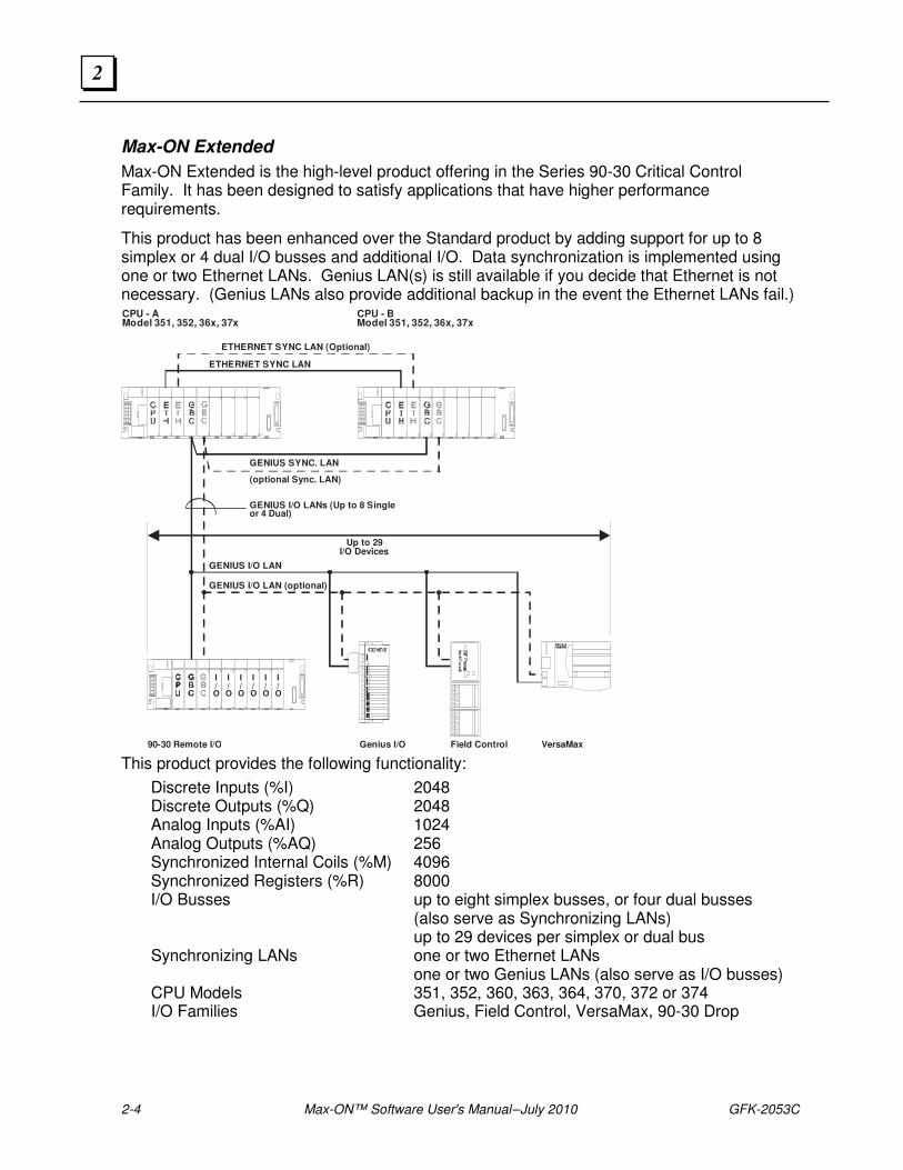
Max-ON Extended
Max-ON Extended is the high-level product offering in the Series 90-30 Critical Control Family. It has been designed to satisfy applications that have higher performance requirements.
This product has been enhanced over the Standard product by adding support for up to 8 simplex or 4 dual I/O busses and additional I/O. Data synchronization is implemented using one or two Ethernet LANs. Genius LAN(s) is still available if you decide that Ethernet is not necessary. (Genius LANs also provide additional backup in the event the Ethernet LANs fail.) CPU - AModel 351, 352, 36x, 37x
CPU - BModel 351, 352, 36x, 37x
90-30 Remote I/O Genius I/O Field Control VersaMax
(optional Sync. LAN)
GENIUS SYNC. LAN
ETHERNET SYNC LAN
ETHERNET SYNC LAN (Optional)
GENIUS I/O LAN
Up to 29I/O Devices
GENIUS I/O LAN (optional)
I/O
I/O
I/O
I/O
I/O
I/O
GENIUS I/O LANs (Up to 8 Singleor 4 Dual)
This product provides the following functionality:
Discrete Inputs (%I) 2048 Discrete Outputs (%Q) 2048 Analog Inputs (%AI) 1024 Analog Outputs (%AQ) 256 Synchronized Internal Coils (%M) 4096 Synchronized Registers (%R) 8000 I/O Busses up to eight simplex busses, or four dual busses (also serve as Synchronizing LANs) up to 29 devices per simplex or dual bus Synchronizing LANs one or two Ethernet LANs one or two Genius LANs (also serve as I/O busses) CPU Models 351, 352, 360, 363, 364, 370, 372 or 374 I/O Families Genius, Field Control, VersaMax, 90-30 Drop
GFK-2053C Chapter 2 System Overview 2-5
2
Software Components
Max-ON software consists of several components, some of which execute in the Hot Standby Controllers, and some of which execute in your programming workstation. A Logic Developer PLC Project provides the basic template for the Logic of the Redundant System. This project is modified by the system designer to add the other necessary Logic to perform the user application, and then the final application is stored in the Controllers using Proficy Logic Developer PLC.
You may think of the software provided in the Project template for the Controllers as “drivers” that handle the complex tasks associated with Hot Standby redundancy. These drivers allow the two Controllers to behave as a single Controller from the perspective of your application.
The Max-ON Configuration Utility allows the system designer to customize the parameters of the Max-ON drivers and to specify the hardware that is contained within the system. The Max-ON Configuration Utility software operates in Windows XP Professional, Windows NT4.0, and Windows 2000 Professional.
The Max-ON Configuration Utility software allows you to define the way your system is constructed and how you want the system to operate. It provides additional information that is not included in the Hardware Configuration files produced by Logic Developer PLC.
The Max-ON software includes a Proficy View Diagnostic Project that allows you to observe the way your system is operating and helps you to diagnose problems. This Project displays the operational status of the redundant system in real time.
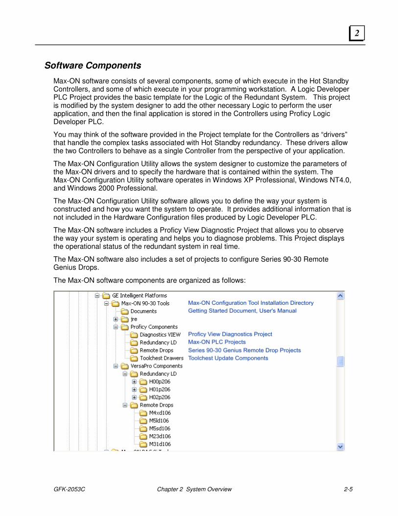
The Max-ON software also includes a set of projects to configure Series 90-30 Remote Genius Drops.
The Max-ON software components are organized as follows:
2-6 Max-ON™ Software User's Manual – July 2010 GFK-2053C
2
Hot Standby Redundancy Operation
During each controller scan, the Max-ON redundancy drivers are solved first, and then your application logic is solved. The Max-ON redundancy drivers handle the following functions:
▪ Determine Mastership – One CPU operates as the Master. The other operates as the Backup. Output devices use the output states from the Master only. In a Max-ON system, the user may specify either PLC to be the preferred Master. If no preference is specified, then Mastership “floats” between the PLCs. The current Master retains its status until it fails or until the user switches Mastership, at which time the Master and Backup exchange their roles.
▪ Transfer Synchronization Data – If the Master fails, the Backup must be prepared to control the process using the latest internal states from the ex-Master. These states may represent such things as latched coils, timer/counter values, PID values, system set points, and perhaps user-calculated values.
▪ Enforce an Orderly PLC Startup – When a failed PLC is returned to service, it must not attempt to assume control of the system prior to being synchronized to the current Master. If both PLCs startup simultaneously, then whichever one was the last valid Master assumes the Mastership.
▪ Process Genius Dual Bus I/O Devices – When the system uses dual Genius I/O busses, input devices are mapped automatically from the active I/O LAN into the PLC’s input reference tables.
▪ Execute Diagnostic Tests – Automatically post time-stamped fault messages into the Max-ON Alarm Table. Identify system problems such as bus faults, loss of devices, change of Mastership, program restart, and power-up event.
GFK-2053C Chapter 2 System Overview 2-7
2
Failover Time
There are two factors that contribute to failover time.
Token Rotation Time: This time interval varies somewhat from one Genius bus to another. It is defined as the update period for the I/O LAN. This period is a function of the number of devices on the LAN, the quantity of input/output data associated with each device, the LAN’s baudrate, and the quantity of global data being transferred. Generally this time period ranges from a few milliseconds to perhaps 100 milliseconds.
Mastership Time: This is the time interval for the Backup PLC to recognize that the Master PLC has failed. It takes one or two PLC scans to determine that the Master has failed. Then it takes an additional scan to activate the output data stream in the Backup PLC.
The actual failover time is the longer of either...
3 Token Rotation Times, or
1 Mastership Time.
Lacking output data from the current Master’s GBC, each output circuit on each device on the I/O LANs will hold its last state for up to 2.5 seconds before it assumes the Default State unless there is output data from the Backup GBC. (This assumes that each device has been configured for either BSM present or for long timeout.) Then the output device will begin using output data from the other GBC.
Synchronized Data Transfers
Data Reference Types
Data from within the following reference ranges may be selected for transfer from the Master to the Backup PLC.
%M00001 ...... %M02048 %M02049 ...... %M04096 (Max-ON Extended Only) %Q00001 ...... %Q02048 %AQ0001 ...... %AQ0256 %R00001 ...... %R08000
Groups
Synchronized data may be transferred in up to 6 groups for each of the data types listed previously. This allows the system to transfer non-contiguous data blocks. The general format uses a Starting Reference, paired with a Length.
2-8 Max-ON™ Software User's Manual – July 2010 GFK-2053C
2
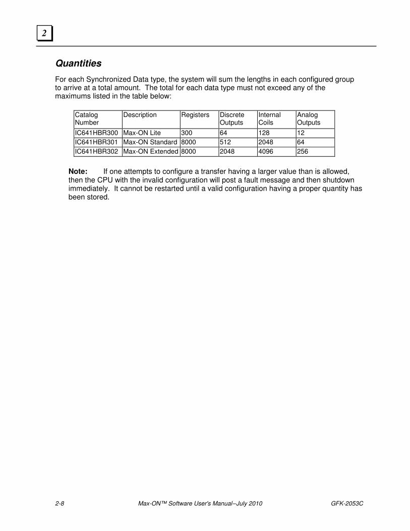
Quantities
For each Synchronized Data type, the system will sum the lengths in each configured group to arrive at a total amount. The total for each data type must not exceed any of the maximums listed in the table below:
Catalog Number
Description Registers Discrete Outputs
Internal Coils
Analog Outputs
IC641HBR300 Max-ON Lite 300 64 128 12
IC641HBR301 Max-ON Standard 8000 512 2048 64
IC641HBR302 Max-ON Extended 8000 2048 4096 256
Note: If one attempts to configure a transfer having a larger value than is allowed, then the CPU with the invalid configuration will post a fault message and then shutdown immediately. It cannot be restarted until a valid configuration having a proper quantity has been stored.
GFK-2053C Chapter 2 System Overview 2-9
2
I/O Bus Topologies
Depending upon the Max-ON product, a system supports the use of single (non-redundant) and/or dual (redundant) busses interfacing to the I/O devices.
Max-ON Lite allows the use of only a single LAN to the I/O devices.
Max-ON Standard supports one redundant LAN or two non-redundant LANs.
Max-ON Extended supports up to four redundant LANs or up to eight non-redundant LANs, or a mixture of the two. However, the system may not have more than eight bus controllers in a PLC.
Redundant busses are superior to non-redundant busses when there is a requirement to protect against cable failures or Genius bus controller failures.
When the primary consideration is to protect against cable failures, then the system designer should consider separating the cables so that a single mechanical failure does not damage both cables.
2-10 Max-ON™ Software User's Manual – July 2010 GFK-2053C
2
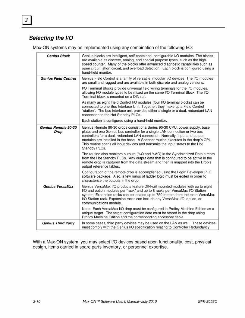
Selecting the I/O
Max-ON systems may be implemented using any combination of the following I/O:
Genius Block Genius blocks are intelligent, self-contained, configurable I/O modules. The blocks are available as discrete, analog, and special purpose types, such as the high-speed counter. Many of the blocks offer advanced diagnostic capabilities such as open circuit, short circuit, and overload detection. Each block is configured using a hand-held monitor.
Genius Field Control Genius Field Control is a family of versatile, modular I/O devices. The I/O modules are small and rugged and are available in both discrete and analog versions.
I/O Terminal Blocks provide universal field wiring terminals for the I/O modules, allowing I/O module types to be mixed on the same I/O Terminal Block. The I/O Terminal block is mounted on a DIN rail.
As many as eight Field Control I/O modules (four I/O terminal blocks) can be connected to one Bus Interface Unit. Together, they make up a Field Control “station”. The bus interface unit provides either a single or a dual, redundant LAN connection to the Hot Standby PLCs.
Each station is configured using a hand-held monitor.
Genius Remote 90-30 Drop
Genius Remote 90-30 drops consist of a Series 90-30 CPU, power supply, base plate, and one Genius bus controller for a single LAN connection or two bus controllers for a dual, redundant LAN connection. Normally, input and output modules are installed in the base. A Scanner routine executes in the drop’s CPU. This routine scans all input devices and transmits the input states to the Hot Standby PLCs.
The routine also monitors outputs (%Q and %AQ) in the Synchronized Data stream from the Hot Standby PLCs. Any output data that is configured to be active in the remote drop is captured from the data stream and then is mapped into the Drop’s output reference tables.
Configuration of the remote drop is accomplished using the Logic Developer PLC software package. Also, a few rungs of ladder logic must be edited in order to characterize the outputs in the drop.
Genius VersaMax Genius VersaMax I/O products feature DIN-rail mounted modules with up to eight I/O and option modules per “rack” and up to 8 racks per VersaMax I/O Station system. Expansion racks can be located up to 750 meters from the main VersaMax I/O Station rack. Expansion racks can include any VersaMax I/O, option, or communications module.
Note: Each VersaMax I/O drop must be configured in Proficy Machine Edition as a unique target. The target configuration data must be stored in the drop using Proficy Machine Edition and the corresponding accessory cable.
Genius Third Party In some cases, third party devices may be used on the LAN as well. These devices must comply with the Genius I/O specification relating to Controller Redundancy.
With a Max-ON system, you may select I/O devices based upon functionality, cost, physical design, items carried in spare parts inventory, or personnel expertise.
GFK-2053C Chapter 2 System Overview 2-11
2
Product Authorization
A Max-ON system will operate in demonstration mode for 22 days. In this mode, all of the system’s capabilities are fully operational. At the end of the period, PLC A will either stop immediately (if it is the backup) or begin an orderly transfer of Mastership to PLC B. If the transfer is successful, then PLC A will shutdown automatically. At this point, the system will be operating in a non-redundant manner.
A Max-ON system that is installed in a production environment MUST be authorized in order to allow PLC A to run indefinitely.
For additional details on product authorization, refer to Chapter 8.

2-12 Max-ON™ Software User's Manual – July 2010 GFK-2053C
2
GFK-2053C 3-1
Building a Max-ON Hot Standby Application
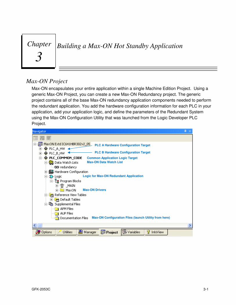
Max-ON Project Max-ON encapsulates your entire application within a single Machine Edition Project. Using a
generic Max-ON Project, you can create a new Max-ON Redundancy project. The generic
project contains all of the base Max-ON redundancy application components needed to perform
the redundant application. You add the hardware configuration information for each PLC in your
application, add your application logic, and define the parameters of the Redundant System
using the Max-ON Configuration Utility that was launched from the Logic Developer PLC
Project.
Chapter
3
Logic for Max-ON Redundant Application
Max-ON Drivers
Max-ON Configuration Files (launch Utility from here)
PLC A Hardware Configuration Target
PLC B Hardware Configuration Target
Common Application Logic Target
Max-ON Data Watch List
3-2 Max-ON™ Software User's Manual – July 2010 GFK-2053C
3
Project Workflow
Step 1 - Gather Information
Gather the information about your system:
I/O Bus topologies and addresses Synchronization LAN locations Module types and locations I/O Devices including bus assignment, bus addresses, circuit references, number of circuits and I/O family type.
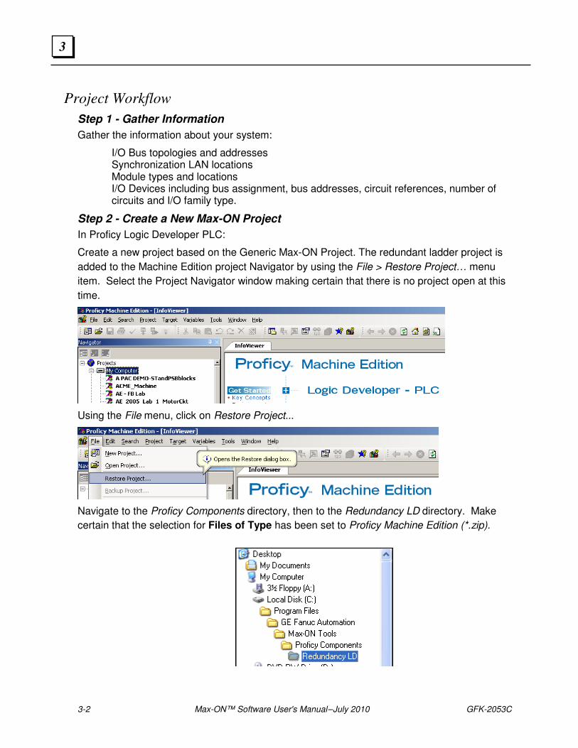
Step 2 - Create a New Max-ON Project
In Proficy Logic Developer PLC:
Create a new project based on the Generic Max-ON Project. The redundant ladder project is
added to the Machine Edition project Navigator by using the File > Restore Project… menu
item. Select the Project Navigator window making certain that there is no project open at this
time.
Using the File menu, click on Restore Project...
Navigate to the Proficy Components directory, then to the Redundancy LD directory. Make
certain that the selection for Files of Type has been set to Proficy Machine Edition (*.zip).
GFK-2053C Chapter 3 Building a Max-ON Hot Standby Application 3-3
3
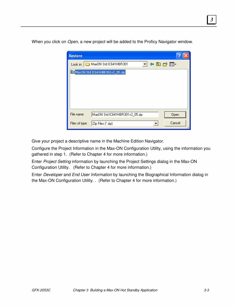
When you click on Open, a new project will be added to the Proficy Navigator window.
Give your project a descriptive name in the Machine Edition Navigator.
Configure the Project Information in the Max-ON Configuration Utility, using the information you
gathered in step 1. (Refer to Chapter 4 for more information.)
Enter Project Setting information by launching the Project Settings dialog in the Max-ON
Configuration Utility. (Refer to Chapter 4 for more information.)
Enter Developer and End User Information by launching the Biographical Information dialog in
the Max-ON Configuration Utility. . (Refer to Chapter 4 for more information.)

3-4 Max-ON™ Software User's Manual – July 2010 GFK-2053C
3
Step 3 - Configure the Controller Hardware
In Logic Developer PLC:
For CPU A:
1. Open the Hardware Configuration for PLC_A_HW target in the Max-ON Project.
2. Configure the PLC hardware for PLC A:
CPU Memory CPU SNP ID Genius Bus Controllers (at least one is required) I/O Devices on the Genius Bus (or Busses) Ethernet Modules Ethernet IP Address and Subnet Mask Device Status Address
3. Store the new hardware configuration into CPU A
4. Set the time and date for CPU A.
For CPU B:
1. Open the Hardware Configuration for PLC_B_HW target in the Max-ON Project.
2. Configure the PLC hardware for PLC B.
CPU Memory CPU SNP ID Genius Bus Controllers (at least one is required) I/O Devices on the Genius Bus (or Busses) Ethernet Modules Ethernet IP Address and Subnet Mask Device Status Address
3. Store the new hardware configuration into CPU B.
4. Set the time and date for CPU B.
GFK-2053C Chapter 3 Building a Max-ON Hot Standby Application 3-5
3
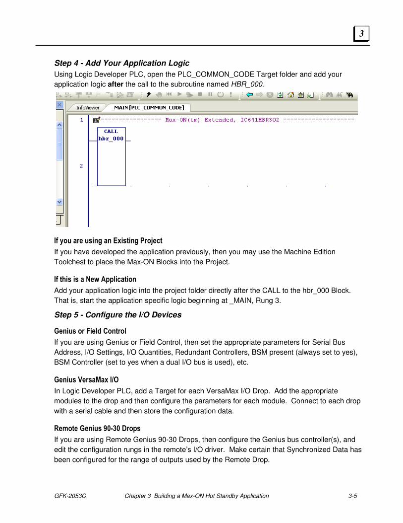
Step 4 - Add Your Application Logic
Using Logic Developer PLC, open the PLC_COMMON_CODE Target folder and add your
application logic after the call to the subroutine named HBR_000.
If you are using an Existing Project
If you have developed the application previously, then you may use the Machine Edition
Toolchest to place the Max-ON Blocks into the Project.
If this is a New Application
Add your application logic into the project folder directly after the CALL to the hbr_000 Block.
That is, start the application specific logic beginning at _MAIN, Rung 3.
Step 5 - Configure the I/O Devices
Genius or Field Control
If you are using Genius or Field Control, then set the appropriate parameters for Serial Bus
Address, I/O Settings, I/O Quantities, Redundant Controllers, BSM present (always set to yes),
BSM Controller (set to yes when a dual I/O bus is used), etc.
Genius VersaMax I/O
In Logic Developer PLC, add a Target for each VersaMax I/O Drop. Add the appropriate
modules to the drop and then configure the parameters for each module. Connect to each drop
with a serial cable and then store the configuration data.
Remote Genius 90-30 Drops
If you are using Remote Genius 90-30 Drops, then configure the Genius bus controller(s), and
edit the configuration rungs in the remote’s I/O driver. Make certain that Synchronized Data has
been configured for the range of outputs used by the Remote Drop.
3-6 Max-ON™ Software User's Manual – July 2010 GFK-2053C
3
Step 6 - Start the System
Divide the system into manageable subsystems that may be verified as independent entities.
I/O Bus
Make certain that the Genius LAN(s) have been installed correctly... LAN polarity and shield
IN/OUT are connected consistently and correctly. Also make certain that terminating resistors
are installed at each end of the LAN(s).
Genius and Field Control – Using a Handheld Monitor, verify that output devices may be turned
ON or OFF from the LAN.
Use the Handheld Monitor check the LAN for any Bus Error activity.
I/O Devices
When Interfacing to CPU A:
With the I/O operating, place CPU A in RUN mode and CPU B in STOP mode.
Verify that the system input devices return real-time values properly.
Verify that system output devices may be controlled from the Output Reference Tables.
Note: This might require that you place a temporary JUMP in your application. The JUMP should be placed immediately after the CALL to HBR_000. The companion label should be placed at the end of _MAIN.
When Interfacing to CPU B:
With the I/O operating, place CPU A in STOP mode and CPU B in RUN mode.
Verify that the system input devices return real-time values properly.
Verify that system output devices may be controlled from the Output Reference Tables.
Hot Standby Operation
Place both CPUs into RUN mode.
Make certain that there is only one Master and only one Backup.
Make certain that there is no preferred Master.
Place CPU B into STOP mode; then place it into RUN mode.
Make certain that Synchronized Data is transferred properly to CPU B.
Transfer Mastership from A to B by placing the CPU A into STOP mode.
Make certain that the I/O did not dropout during the transfer.
Place CPU A into RUN mode.
Make certain that it becomes a Backup properly.
Transfer Mastership from B to A by placing the CPU B into STOP mode.

GFK-2053C Chapter 3 Building a Max-ON Hot Standby Application 3-7
3
Make certain that the I/O did not dropout during the transfer.
Place CPU B into RUN mode.
Make certain that it becomes a Backup properly.
Make certain that Synchronized Data is transferred properly to CPU B.
3-8 Max-ON™ Software User's Manual – July 2010 GFK-2053C
3
Step 7 - Debug the System
Use the Max-ON View Diagnostic Project
Restore the Proficy View Project from the installation directory into Proficy Machine Edition.
Enter the Ethernet Addresses of PLC A and PLC B into the Proficy View Project.
Download and Run the View Project on your workstation.
Examine the Alarm and the Real-time Status displays.
Simplify the System
Here are a few suggestions from other system developers that have worked well.
Turn OFF one PLC and troubleshoot the system using the remaining one.
Disable Max-ON drivers by placing an #ALW_OFF contact prior to the call to HBR_000. Now
determine if input/output devices operate properly. This will require that you modify the
hardware configuration for the Genius bus controllers. Place them in “Enable at Start”. Don’t
forget to change the configuration to “Disable at Start” when it is time to place the system into
its final, redundant operation.
Disable your application code and troubleshoot the Max-ON functionality. Check to make
certain that synchronized data items transfer properly. Check to make certain that the Hot
Standby CPUs will exchange mastership properly.

GFK-2053C Chapter 3 Building a Max-ON Hot Standby Application 3-9
3

3-10 Max-ON™ Software User's Manual – July 2010 GFK-2053C
3
GFK-2053C 4-1
The Max-ON Configuration Utility
The Max-ON Configuration Utility is used to create or edit the operating parameters used by
the Max-ON redundancy drivers. These parameters specify such things as, bus topologies,
I/O addresses, and definitions for the ranges of synchronized data transfers.
Max-ON Projects
A Max-ON Project is a collection of items needed to define the elements of a redundant
system. If you inspected a Max-ON Project using Logic Developer PLC, you would see that it
consists of a Machine Edition Project with 3 Targets:
• PLC_A_HW – This target contains the hardware configuration for PLC A. It must be
edited to reflect the hardware settings and components of PLC A in your system.
Then it must be downloaded to PLC A (only).
• PLC_B_HW – This target contains the hardware configuration for PLC B. It must be
edited to reflect the hardware settings and components of PLC B in your system. It
will be very similar to PLC A hardware configuration, except for certain items such IP
addresses, and Genius bus controller settings. In a similar fashion, this configuration
must be downloaded to PLC B (only).
• PLC_COMMON_CODE – This contains the core redundancy logic for the Max-ON
redundancy application. You must add your application logic starting in the rung that
follows the call to the core Max-ON logic (hbr_000). The logic from this target will be
downloaded to both PLC A and PLC B. Note that the download consists of the PLC
Logic Only, the Hardware Configuration option must be unchecked.
Chapter
4
4-2 Max-ON™ Software User's Manual – July 2010 GFK-2053C
4
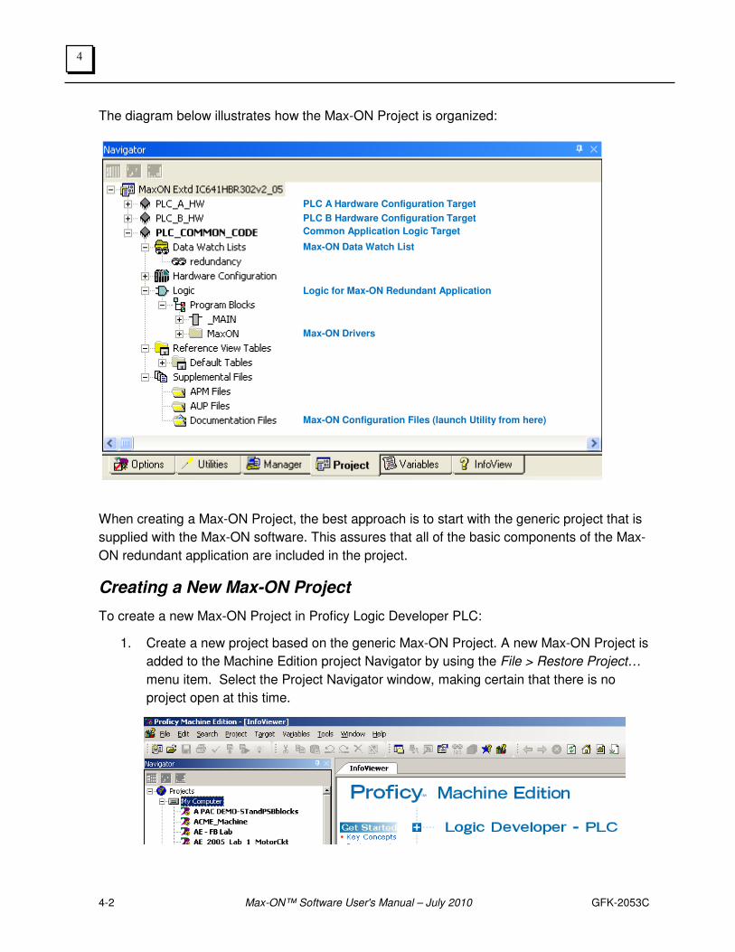
The diagram below illustrates how the Max-ON Project is organized:
When creating a Max-ON Project, the best approach is to start with the generic project that is
supplied with the Max-ON software. This assures that all of the basic components of the Max-
ON redundant application are included in the project.
Creating a New Max-ON Project
To create a new Max-ON Project in Proficy Logic Developer PLC:
1. Create a new project based on the generic Max-ON Project. A new Max-ON Project is
added to the Machine Edition project Navigator by using the File > Restore Project…
menu item. Select the Project Navigator window, making certain that there is no
project open at this time.
Logic for Max-ON Redundant Application
Max-ON Drivers
Max-ON Configuration Files (launch Utility from here)
PLC A Hardware Configuration Target
PLC B Hardware Configuration Target
Common Application Logic Target
Max-ON Data Watch List
GFK-2053C Chapter 4 The Max-ON Configuration Utility 4-3
4
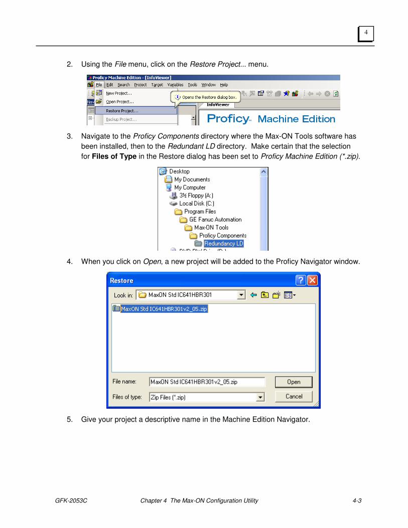
2. Using the File menu, click on the Restore Project... menu.
3. Navigate to the Proficy Components directory where the Max-ON Tools software has
been installed, then to the Redundant LD directory. Make certain that the selection
for Files of Type in the Restore dialog has been set to Proficy Machine Edition (*.zip).
4. When you click on Open, a new project will be added to the Proficy Navigator window.
5. Give your project a descriptive name in the Machine Edition Navigator.
4-4 Max-ON™ Software User's Manual – July 2010 GFK-2053C
4
Launching the Max-ON Configuration Utility
The Max-ON Configuration Utility is launched from the Max-ON Machine Edition Project. For
example, open the project that you created in the previous section. Navigate to the Max-ON
Configuration Utility by following these steps:
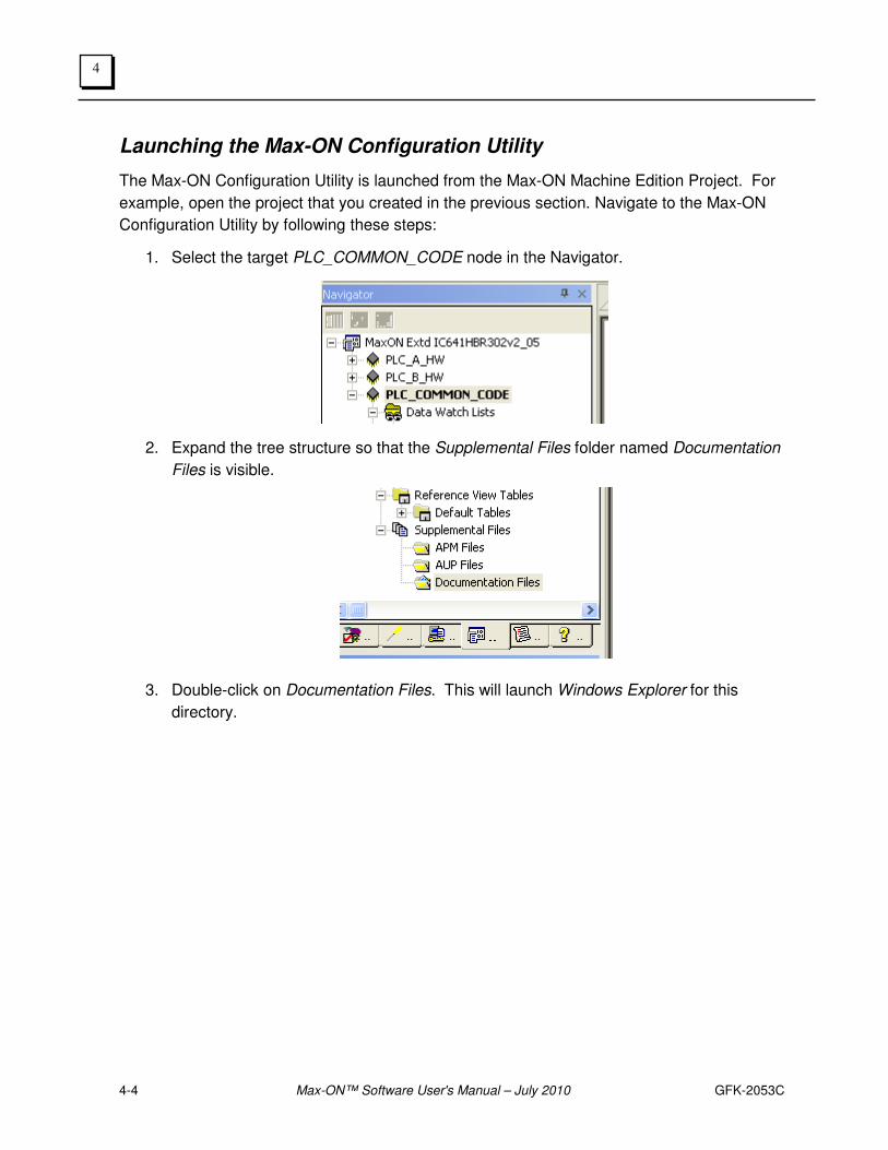
1. Select the target PLC_COMMON_CODE node in the Navigator.
2. Expand the tree structure so that the Supplemental Files folder named Documentation
Files is visible.
3. Double-click on Documentation Files. This will launch Windows Explorer for this
directory.
GFK-2053C Chapter 4 The Max-ON Configuration Utility 4-5
4
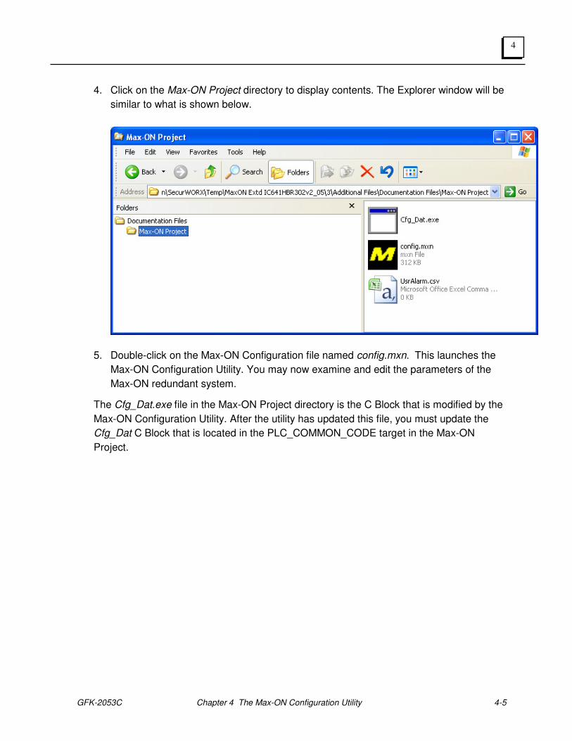
4. Click on the Max-ON Project directory to display contents. The Explorer window will be
similar to what is shown below.
5. Double-click on the Max-ON Configuration file named config.mxn. This launches the
Max-ON Configuration Utility. You may now examine and edit the parameters of the
Max-ON redundant system.
The Cfg_Dat.exe file in the Max-ON Project directory is the C Block that is modified by the
Max-ON Configuration Utility. After the utility has updated this file, you must update the
Cfg_Dat C Block that is located in the PLC_COMMON_CODE target in the Max-ON
Project.
4-6 Max-ON™ Software User's Manual – July 2010 GFK-2053C
4
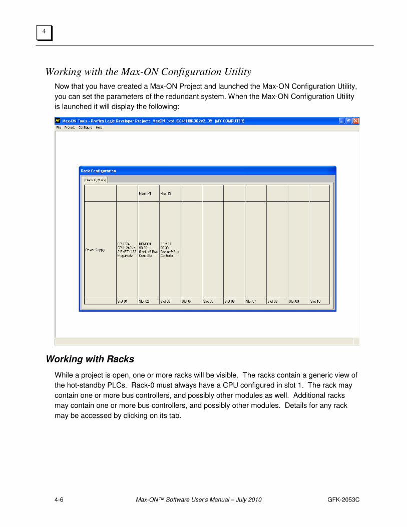
Working with the Max-ON Configuration Utility
Now that you have created a Max-ON Project and launched the Max-ON Configuration Utility,
you can set the parameters of the redundant system. When the Max-ON Configuration Utility
is launched it will display the following:
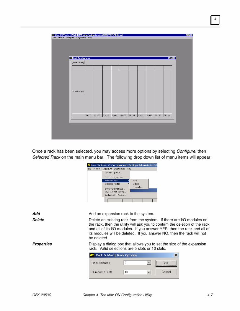
Working with Racks
While a project is open, one or more racks will be visible. The racks contain a generic view of
the hot-standby PLCs. Rack-0 must always have a CPU configured in slot 1. The rack may
contain one or more bus controllers, and possibly other modules as well. Additional racks
may contain one or more bus controllers, and possibly other modules. Details for any rack
may be accessed by clicking on its tab.
GFK-2053C Chapter 4 The Max-ON Configuration Utility 4-7
4
Once a rack has been selected, you may access more options by selecting Configure, then
Selected Rack on the main menu bar. The following drop down list of menu items will appear:
Add Add an expansion rack to the system.
Delete Delete an existing rack from the system. If there are I/O modules on the rack, then the utility will ask you to confirm the deletion of the rack and all of its I/O modules. If you answer YES, then the rack and all of its modules will be deleted. If you answer NO, then the rack will not be deleted.
Properties Display a dialog box that allows you to set the size of the expansion rack. Valid selections are 5 slots or 10 slots.
4-8 Max-ON™ Software User's Manual – July 2010 GFK-2053C
4
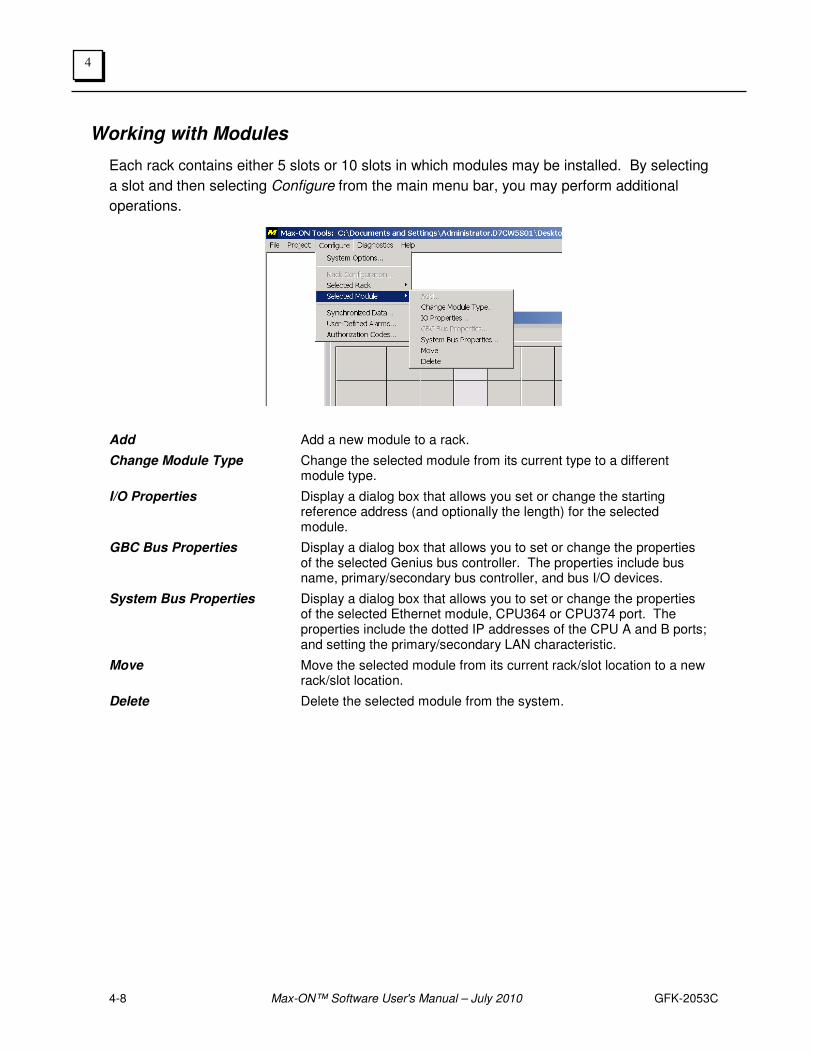
Working with Modules
Each rack contains either 5 slots or 10 slots in which modules may be installed. By selecting
a slot and then selecting Configure from the main menu bar, you may perform additional
operations.
Add Add a new module to a rack.
Change Module Type Change the selected module from its current type to a different module type.
I/O Properties Display a dialog box that allows you set or change the starting reference address (and optionally the length) for the selected module.
GBC Bus Properties Display a dialog box that allows you to set or change the properties of the selected Genius bus controller. The properties include bus name, primary/secondary bus controller, and bus I/O devices.
System Bus Properties Display a dialog box that allows you to set or change the properties of the selected Ethernet module, CPU364 or CPU374 port. The properties include the dotted IP addresses of the CPU A and B ports; and setting the primary/secondary LAN characteristic.
Move Move the selected module from its current rack/slot location to a new rack/slot location.
Delete Delete the selected module from the system.
GFK-2053C Chapter 4 The Max-ON Configuration Utility 4-9
4
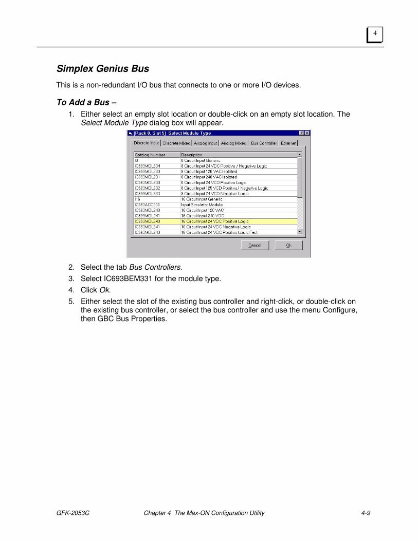
Simplex Genius Bus
This is a non-redundant I/O bus that connects to one or more I/O devices.
To Add a Bus –
1. Either select an empty slot location or double-click on an empty slot location. The Select Module Type dialog box will appear.
2. Select the tab Bus Controllers.
3. Select IC693BEM331 for the module type.
4. Click Ok.
5. Either select the slot of the existing bus controller and right-click, or double-click on the existing bus controller, or select the bus controller and use the menu Configure, then GBC Bus Properties.
4-10 Max-ON™ Software User's Manual – July 2010 GFK-2053C
4
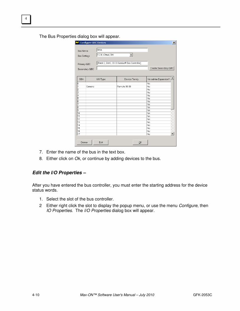
The Bus Properties dialog box will appear.
7. Enter the name of the bus in the text box.
8. Either click on Ok, or continue by adding devices to the bus.
Edit the I/O Properties –
After you have entered the bus controller, you must enter the starting address for the device status words.
1. Select the slot of the bus controller.
2 Either right click the slot to display the popup menu, or use the menu Configure, then IO Properties. The I/O Properties dialog box will appear.

GFK-2053C Chapter 4 The Max-ON Configuration Utility 4-11
4
3. Enter a status address. (A suggested practice is to address devices such as Genius bus controllers, Ethernet modules, etc., at high addresses. This leaves the low addresses available for Input devices connected to your field sensors.)
4. Click Ok to complete the session.
4-12 Max-ON™ Software User's Manual – July 2010 GFK-2053C
4
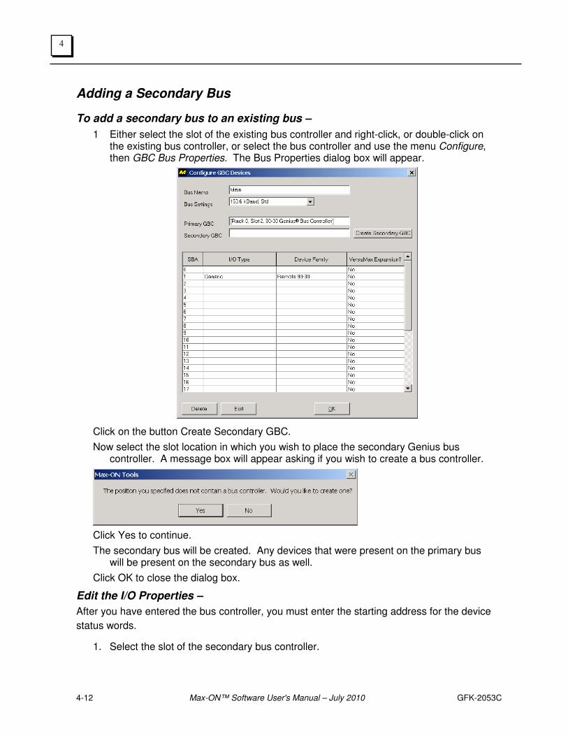
Adding a Secondary Bus
To add a secondary bus to an existing bus –
1 Either select the slot of the existing bus controller and right-click, or double-click on the existing bus controller, or select the bus controller and use the menu Configure, then GBC Bus Properties. The Bus Properties dialog box will appear.
Click on the button Create Secondary GBC.
Now select the slot location in which you wish to place the secondary Genius bus controller. A message box will appear asking if you wish to create a bus controller.
Click Yes to continue.
The secondary bus will be created. Any devices that were present on the primary bus will be present on the secondary bus as well.
Click OK to close the dialog box.
Edit the I/O Properties –
After you have entered the bus controller, you must enter the starting address for the device
status words.
1. Select the slot of the secondary bus controller.

GFK-2053C Chapter 4 The Max-ON Configuration Utility 4-13
4
2. Either right click the slot to display the popup menu, or use the menu Configure, then IO Properties. The I/O Properties dialog box will appear.
3. Enter a status address. (A suggested practice is to address devices such as Genius bus controllers, Ethernet modules, etc., at high addresses. This leaves the low addresses to Input devices connected to your field sensors.)
4. Click Ok to complete the session.
4-14 Max-ON™ Software User's Manual – July 2010 GFK-2053C
4
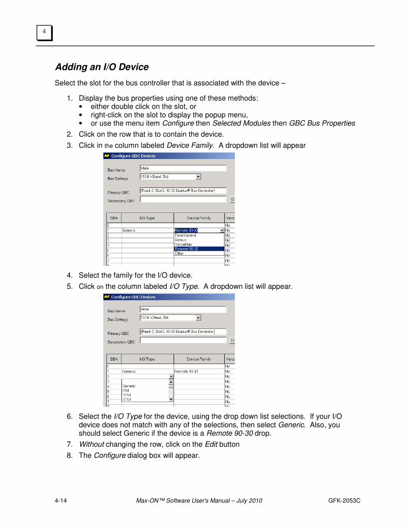
Adding an I/O Device
Select the slot for the bus controller that is associated with the device –
1. Display the bus properties using one of these methods: • either double click on the slot, or • right-click on the slot to display the popup menu, • or use the menu item Configure then Selected Modules then GBC Bus Properties
2. Click on the row that is to contain the device.
3. Click in the column labeled Device Family. A dropdown list will appear
4. Select the family for the I/O device.
5. Click on the column labeled I/O Type. A dropdown list will appear.
6. Select the I/O Type for the device, using the drop down list selections. If your I/O device does not match with any of the selections, then select Generic. Also, you should select Generic if the device is a Remote 90-30 drop.
7. Without changing the row, click on the Edit button
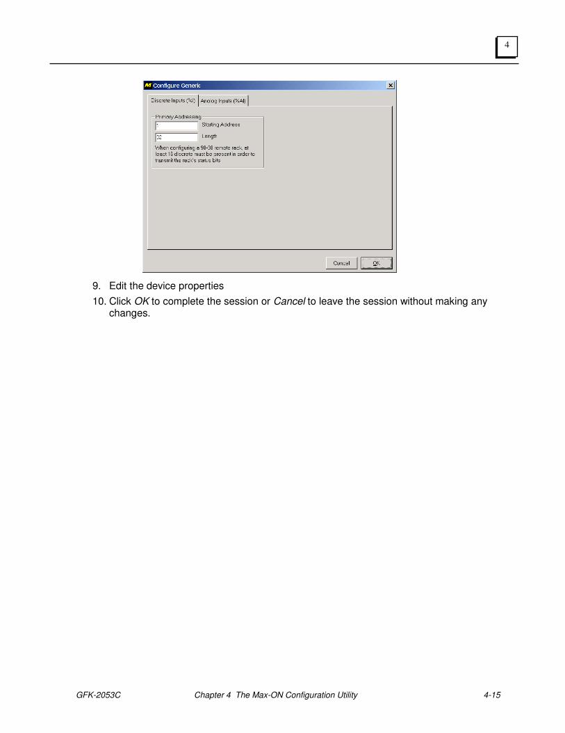
8. The Configure dialog box will appear.
GFK-2053C Chapter 4 The Max-ON Configuration Utility 4-15
4
9. Edit the device properties
10. Click OK to complete the session or Cancel to leave the session without making any changes.
4-16 Max-ON™ Software User's Manual – July 2010 GFK-2053C
4
Editing an I/O Device
1 Using the mouse, select the slot that corresponds to the bus containing the device.
2 Display the bus properties using one of these methods:
• either double click on the slot, or
• right-click on the slot to display the popup menu, or
• use the menu item Configure then Selected Modules then GBC Bus Properties
3 Click on the row that contains the device.
4 Click on the Edit button.
5 The Configure dialog box will appear.
6 Edit the device properties
7 Click OK to complete session or Cancel to leave the session without making any changes.
Deleting an I/O Device
1. Using the mouse, select the slot that corresponds to the bus containing the device.
2 Display the bus properties using one of these methods:
• either double click on the slot, or
• right-click on the slot to display the popup menu, or
• use the menu item Configure then Selected Modules then GBC Bus Properties
3 Click on the row that contains the device.
4 Click on the Delete button.
5 The device has been deleted.
GFK-2053C Chapter 4 The Max-ON Configuration Utility 4-17
4
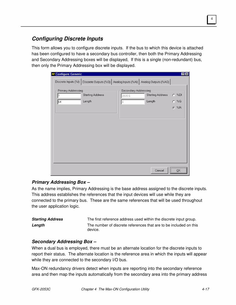
Configuring Discrete Inputs
This form allows you to configure discrete inputs. If the bus to which this device is attached
has been configured to have a secondary bus controller, then both the Primary Addressing
and Secondary Addressing boxes will be displayed, If this is a single (non-redundant) bus,
then only the Primary Addressing box will be displayed.
Primary Addressing Box –
As the name implies, Primary Addressing is the base address assigned to the discrete inputs.
This address establishes the references that the input devices will use while they are
connected to the primary bus. These are the same references that will be used throughout
the user application logic.
Starting Address The first reference address used within the discrete input group.
Length The number of discrete references that are to be included on this device.
Secondary Addressing Box –
When a dual bus is employed, there must be an alternate location for the discrete inputs to
report their status. The alternate location is the reference area in which the inputs will appear
while they are connected to the secondary I/O bus.
Max-ON redundancy drivers detect when inputs are reporting into the secondary reference
area and then map the inputs automatically from the secondary area into the primary address
4-18 Max-ON™ Software User's Manual – July 2010 GFK-2053C
4
locations. This permits the user-application to be written with references to the primary
addresses only.
Starting Address The first reference address used in the secondary (alternate) reference table. You cannot enter a value here. However, you may select the desired reference table for the alternate location.
• If the Primary Address Length is a multiple of 16, then the inputs will be mapped into the 90-30 register table.
• If the Length is an odd multiple of 8, then the inputs may be mapped into either %I or %G references.
Length The number of discrete references that are to be included on this device. This is a read-only value that is generated from the number that was entered into the Primary Address box.
GFK-2053C Chapter 4 The Max-ON Configuration Utility 4-19
4
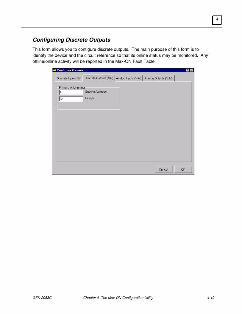
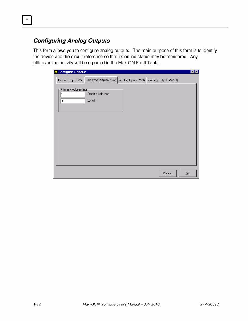
Configuring Discrete Outputs
This form allows you to configure discrete outputs. The main purpose of this form is to
identify the device and the circuit reference so that its online status may be monitored. Any
offline/online activity will be reported in the Max-ON Fault Table.
4-20 Max-ON™ Software User's Manual – July 2010 GFK-2053C
4
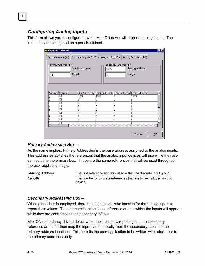
Configuring Analog Inputs
This form allows you to configure how the Max-ON driver will process analog inputs. The
inputs may be configured on a per circuit basis.
Primary Addressing Box –
As the name implies, Primary Addressing is the base address assigned to the analog inputs.
This address establishes the references that the analog input devices will use while they are
connected to the primary bus. These are the same references that will be used throughout
the user application logic.
Starting Address The first reference address used within the discrete input group.
Length The number of discrete references that are to be included on this device
Secondary Addressing Box –
When a dual bus is employed, there must be an alternate location for the analog inputs to
report their values. The alternate location is the reference area in which the inputs will appear
while they are connected to the secondary I/O bus.
Max-ON redundancy drivers detect when the inputs are reporting into the secondary
reference area and then map the inputs automatically from the secondary area into the
primary address locations. This permits the user-application to be written with references to
the primary addresses only.
GFK-2053C Chapter 4 The Max-ON Configuration Utility 4-21
4
Starting Address The first reference address used in the secondary (alternate) reference table. You cannot enter a value here. The reference will always be equal to the primary reference plus an offset of 1024.
Length The number of discrete references that are to be included on this device. This is a read-only value that is generated from the number that was entered into the Primary Address box.
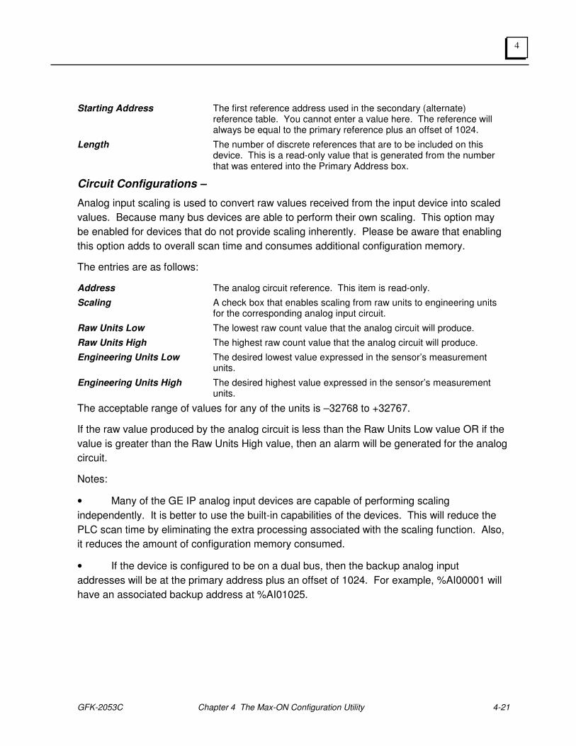
Circuit Configurations –
Analog input scaling is used to convert raw values received from the input device into scaled
values. Because many bus devices are able to perform their own scaling. This option may
be enabled for devices that do not provide scaling inherently. Please be aware that enabling
this option adds to overall scan time and consumes additional configuration memory.
The entries are as follows:
Address The analog circuit reference. This item is read-only.
Scaling A check box that enables scaling from raw units to engineering units for the corresponding analog input circuit.
Raw Units Low The lowest raw count value that the analog circuit will produce.
Raw Units High The highest raw count value that the analog circuit will produce.
Engineering Units Low The desired lowest value expressed in the sensor’s measurement units.
Engineering Units High The desired highest value expressed in the sensor’s measurement units.
The acceptable range of values for any of the units is –32768 to +32767.
If the raw value produced by the analog circuit is less than the Raw Units Low value OR if the
value is greater than the Raw Units High value, then an alarm will be generated for the analog
circuit.
Notes:
• Many of the GE IP analog input devices are capable of performing scaling
independently. It is better to use the built-in capabilities of the devices. This will reduce the
PLC scan time by eliminating the extra processing associated with the scaling function. Also,
it reduces the amount of configuration memory consumed.
• If the device is configured to be on a dual bus, then the backup analog input
addresses will be at the primary address plus an offset of 1024. For example, %AI00001 will
have an associated backup address at %AI01025.
4-22 Max-ON™ Software User's Manual – July 2010 GFK-2053C
4
Configuring Analog Outputs
This form allows you to configure analog outputs. The main purpose of this form is to identify
the device and the circuit reference so that its online status may be monitored. Any
offline/online activity will be reported in the Max-ON Fault Table.
GFK-2053C Chapter 4 The Max-ON Configuration Utility 4-23
4
Configuring the Secondary Address
On dual bus systems, discrete and analog inputs are mapped from the primary bus
controller’s buffers into the normal input reference tables.
Inputs from the secondary bus controller are placed into an alternate area and then the Max-
ON PLC driver remaps the alternate states into the table area used by the primary.
Remapping occurs whenever the device is detected as being present on the secondary bus,
but not present on the primary. (In most instances the data will be available on one of the
busses, but not both. The exception is for Remote 90-30 drops, in which case, there are bus
controllers on each bus.)
Analog Inputs –
For analog inputs, the alternate addressing is fixed at the primary’s address reference plus
1024. Thus an analog input circuit addressed at %AI00001 will have an alternate, or
secondary address, at %AI01025.
Discrete Inputs –
For discrete inputs, the addressing is more flexible.
• If the primary address is on a word multiple (i.e, 1, 17, 33, etc.) AND the length
is a word multiple (i.e., 16, 32, 48, etc.), then the secondary addresss will be mapped
into %R space.
• If the primary address does not meet the criteria above, then the user may
select an alternate address at either a %G reference or a %I reference.
Project Configuration Report –
The configuration utility will calculate secondary bus references automatically. Please use the
configuration report to obtain the information that is needed to configure the secondary bus
controllers for discrete and analog inputs.
4-24 Max-ON™ Software User's Manual – July 2010 GFK-2053C
4
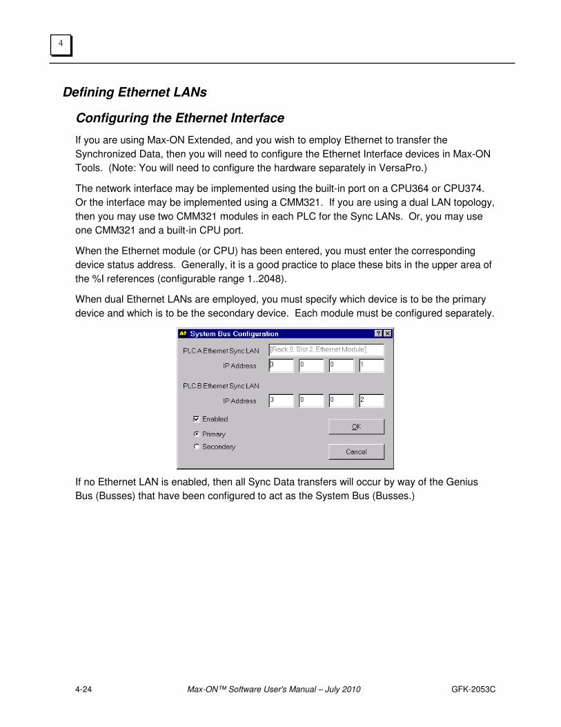
Defining Ethernet LANs
Configuring the Ethernet Interface
If you are using Max-ON Extended, and you wish to employ Ethernet to transfer the
Synchronized Data, then you will need to configure the Ethernet Interface devices in Max-ON
Tools. (Note: You will need to configure the hardware separately in VersaPro.)
The network interface may be implemented using the built-in port on a CPU364 or CPU374.
Or the interface may be implemented using a CMM321. If you are using a dual LAN topology,
then you may use two CMM321 modules in each PLC for the Sync LANs. Or, you may use
one CMM321 and a built-in CPU port.
When the Ethernet module (or CPU) has been entered, you must enter the corresponding
device status address. Generally, it is a good practice to place these bits in the upper area of
the %I references (configurable range 1..2048).
When dual Ethernet LANs are employed, you must specify which device is to be the primary
device and which is to be the secondary device. Each module must be configured separately.
If no Ethernet LAN is enabled, then all Sync Data transfers will occur by way of the Genius
Bus (Busses) that have been configured to act as the System Bus (Busses.)
GFK-2053C Chapter 4 The Max-ON Configuration Utility 4-25
4
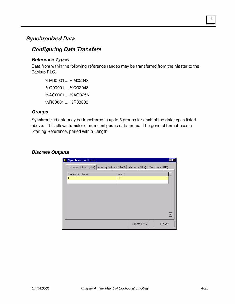
Synchronized Data
Configuring Data Transfers
Reference Types
Data from within the following reference ranges may be transferred from the Master to the
Backup PLC.
%M00001 .... %M02048
%Q00001 .... %Q02048
%AQ0001 .... %AQ0256
%R00001 .... %R08000
Groups
Synchronized data may be transferred in up to 6 groups for each of the data types listed
above. This allows transfer of non-contiguous data areas. The general format uses a
Starting Reference, paired with a Length.
Discrete Outputs
4-26 Max-ON™ Software User's Manual – July 2010 GFK-2053C
4
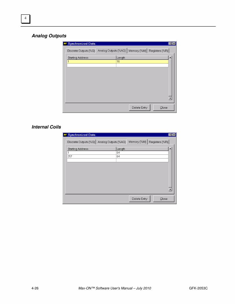
Analog Outputs
Internal Coils
GFK-2053C Chapter 4 The Max-ON Configuration Utility 4-27
4
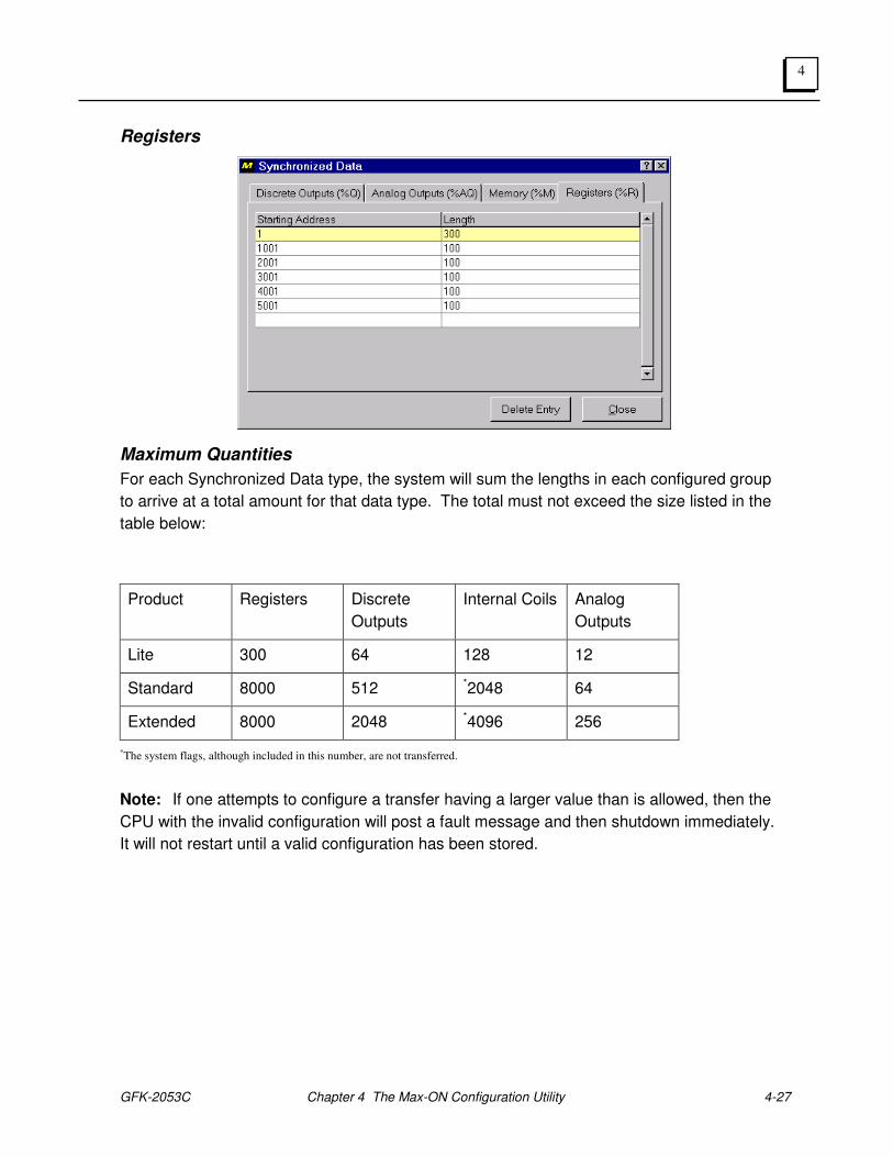
Registers
Maximum Quantities
For each Synchronized Data type, the system will sum the lengths in each configured group
to arrive at a total amount for that data type. The total must not exceed the size listed in the
table below:
Product Registers Discrete
Outputs
Internal Coils Analog
Outputs
Lite 300 64 128 12
Standard 8000 512 *2048 64
Extended 8000 2048 *4096 256
*The system flags, although included in this number, are not transferred.
Note: If one attempts to configure a transfer having a larger value than is allowed, then the
CPU with the invalid configuration will post a fault message and then shutdown immediately.
It will not restart until a valid configuration has been stored.
4-28 Max-ON™ Software User's Manual – July 2010 GFK-2053C
4
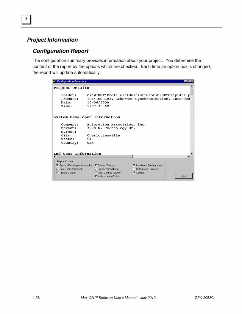
Project Information
Configuration Report
The configuration summary provides information about your project. You determine the
content of the report by the options which are checked. Each time an option box is changed,
the report will update automatically.
GFK-2053C Chapter 4 The Max-ON Configuration Utility 4-29
4
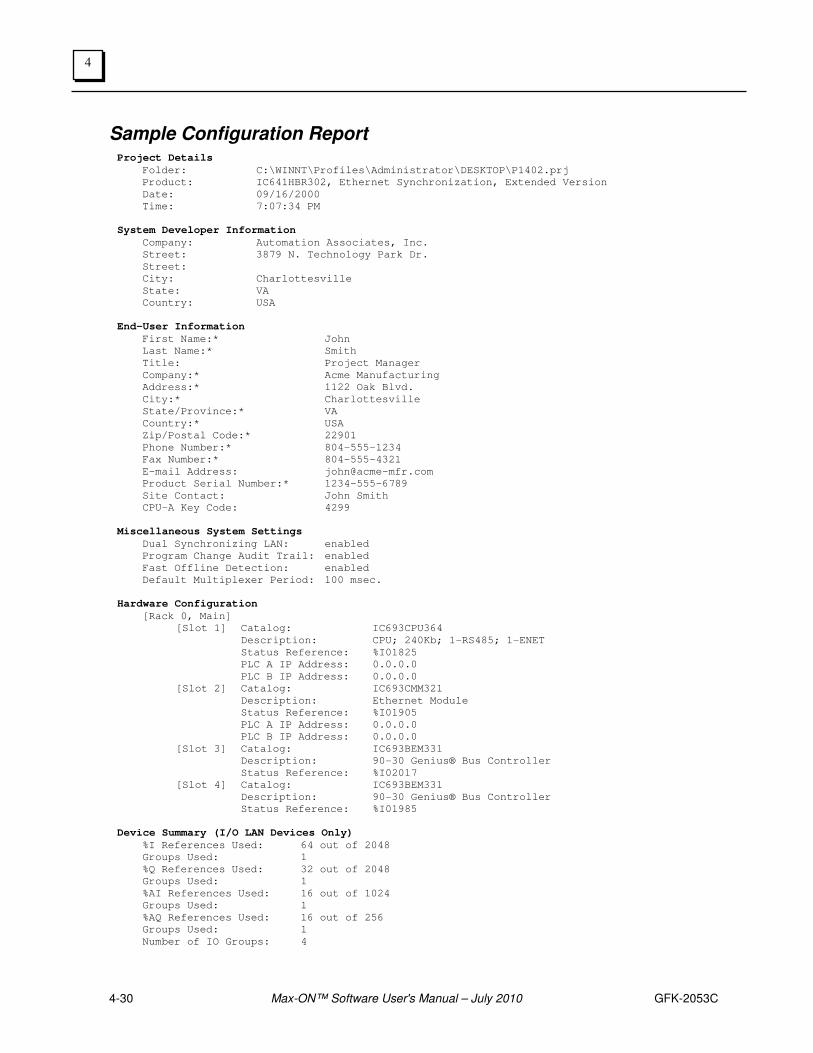
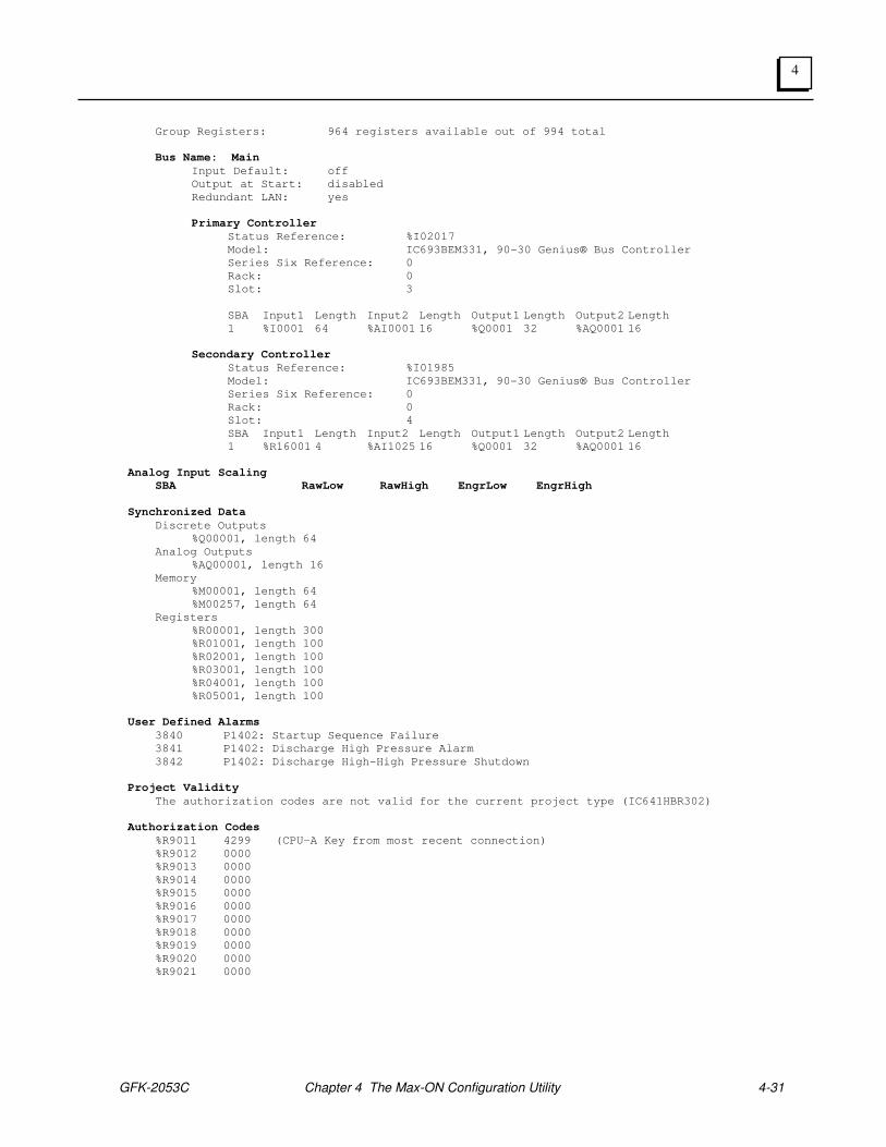
Here are the options and their descriptions.
System Developer Info The information that was entered onto the workstation. This is stored in the System Registry, but not in the project database.
End User Info The information that was entered in the End User dialog. It is stored in the project database. The information includes company name, contact name, address, etc.
Project Validity This is a list of any errors that have been detected during a Project-Save.
System Settings These settings relate to the parameter that were entered in the System Options.
Synch. Data This is a listing of all of the Synchronized Variables and all groups in each type.
User Defined Alarms This is a listing of any User-Defined Alarms that have been entered.
Authorization Codes This is a listing of the current value for the PLC Key Code along with the current entries for the Authorization codes.
Hardware Config. This lists configuration parameters associated with the CPU and all Genius bus controllers, Ethernet modules, and rack-based I/O modules.
I/O Device Summary This lists the configuration parameters for all Genius bus I/O devices.
Scaling This lists the scaling parameters for any analog input groups that have been Enabled.
4-30 Max-ON™ Software User's Manual – July 2010 GFK-2053C
4
Sample Configuration Report Project Details
Folder: C:\WINNT\Profiles\Administrator\DESKTOP\P1402.prj
Product: IC641HBR302, Ethernet Synchronization, Extended Version
Date: 09/16/2000
Time: 7:07:34 PM
System Developer Information
Company: Automation Associates, Inc.
Street: 3879 N. Technology Park Dr.
Street:
City: Charlottesville
State: VA
Country: USA
End-User Information
First Name:* John
Last Name:* Smith
Title: Project Manager
Company:* Acme Manufacturing
Address:* 1122 Oak Blvd.
City:* Charlottesville
State/Province:* VA
Country:* USA
Zip/Postal Code:* 22901
Phone Number:* 804-555-1234
Fax Number:* 804-555-4321
E-mail Address: [email protected]
Product Serial Number:* 1234-555-6789
Site Contact: John Smith
CPU-A Key Code: 4299
Miscellaneous System Settings
Dual Synchronizing LAN: enabled
Program Change Audit Trail: enabled
Fast Offline Detection: enabled
Default Multiplexer Period: 100 msec.
Hardware Configuration
[Rack 0, Main]
[Slot 1] Catalog: IC693CPU364
Description: CPU; 240Kb; 1-RS485; 1-ENET
Status Reference: %I01825
PLC A IP Address: 0.0.0.0
PLC B IP Address: 0.0.0.0
[Slot 2] Catalog: IC693CMM321
Description: Ethernet Module
Status Reference: %I01905
PLC A IP Address: 0.0.0.0
PLC B IP Address: 0.0.0.0
[Slot 3] Catalog: IC693BEM331
Description: 90-30 Genius® Bus Controller
Status Reference: %I02017
[Slot 4] Catalog: IC693BEM331
Description: 90-30 Genius® Bus Controller
Status Reference: %I01985
Device Summary (I/O LAN Devices Only)
%I References Used: 64 out of 2048
Groups Used: 1
%Q References Used: 32 out of 2048
Groups Used: 1
%AI References Used: 16 out of 1024
Groups Used: 1
%AQ References Used: 16 out of 256
Groups Used: 1
Number of IO Groups: 4
GFK-2053C Chapter 4 The Max-ON Configuration Utility 4-31
4
Group Registers: 964 registers available out of 994 total
Bus Name: Main
Input Default: off
Output at Start: disabled
Redundant LAN: yes
Primary Controller
Status Reference: %I02017
Model: IC693BEM331, 90-30 Genius® Bus Controller
Series Six Reference: 0
Rack: 0
Slot: 3
SBA Input1 Length Input2 Length Output1 Length Output2 Length
1 %I0001 64 %AI0001 16 %Q0001 32 %AQ0001 16
Secondary Controller
Status Reference: %I01985
Model: IC693BEM331, 90-30 Genius® Bus Controller
Series Six Reference: 0
Rack: 0
Slot: 4
SBA Input1 Length Input2 Length Output1 Length Output2 Length
1 %R16001 4 %AI1025 16 %Q0001 32 %AQ0001 16
Analog Input Scaling SBA RawLow RawHigh EngrLow EngrHigh
Synchronized Data
Discrete Outputs
%Q00001, length 64
Analog Outputs
%AQ00001, length 16
Memory
%M00001, length 64
%M00257, length 64
Registers
%R00001, length 300
%R01001, length 100
%R02001, length 100
%R03001, length 100
%R04001, length 100
%R05001, length 100
User Defined Alarms
3840 P1402: Startup Sequence Failure
3841 P1402: Discharge High Pressure Alarm
3842 P1402: Discharge High-High Pressure Shutdown
Project Validity
The authorization codes are not valid for the current project type (IC641HBR302)
Authorization Codes
%R9011 4299 (CPU-A Key from most recent connection)
%R9012 0000
%R9013 0000
%R9014 0000
%R9015 0000
%R9016 0000
%R9017 0000
%R9018 0000
%R9019 0000
%R9020 0000
%R9021 0000
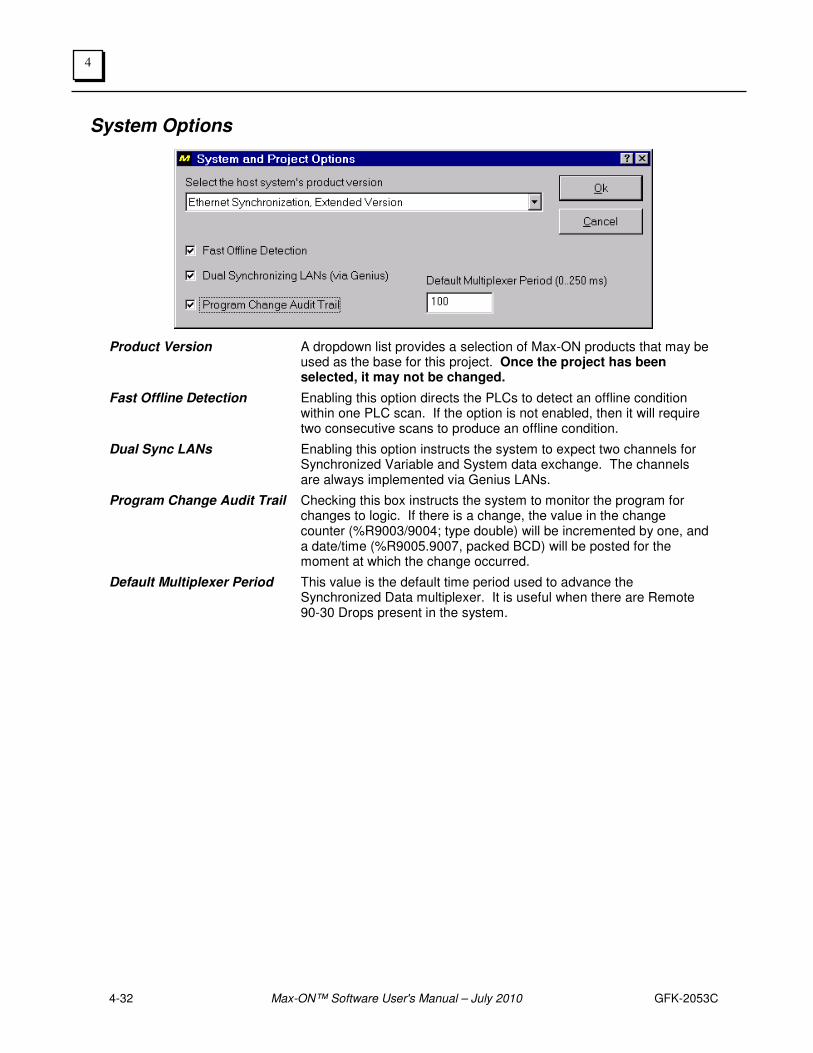
4-32 Max-ON™ Software User's Manual – July 2010 GFK-2053C
4
System Options
Product Version A dropdown list provides a selection of Max-ON products that may be used as the base for this project. Once the project has been selected, it may not be changed.
Fast Offline Detection Enabling this option directs the PLCs to detect an offline condition within one PLC scan. If the option is not enabled, then it will require two consecutive scans to produce an offline condition.
Dual Sync LANs Enabling this option instructs the system to expect two channels for Synchronized Variable and System data exchange. The channels are always implemented via Genius LANs.
Program Change Audit Trail Checking this box instructs the system to monitor the program for changes to logic. If there is a change, the value in the change counter (%R9003/9004; type double) will be incremented by one, and a date/time (%R9005.9007, packed BCD) will be posted for the moment at which the change occurred.
Default Multiplexer Period This value is the default time period used to advance the Synchronized Data multiplexer. It is useful when there are Remote 90-30 Drops present in the system.
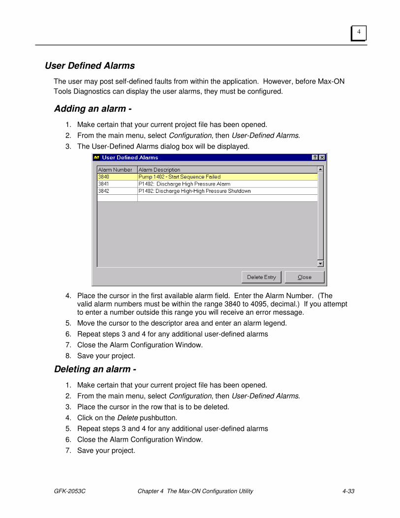
GFK-2053C Chapter 4 The Max-ON Configuration Utility 4-33
4
User Defined Alarms
The user may post self-defined faults from within the application. However, before Max-ON
Tools Diagnostics can display the user alarms, they must be configured.
Adding an alarm -
1. Make certain that your current project file has been opened.
2. From the main menu, select Configuration, then User-Defined Alarms.
3. The User-Defined Alarms dialog box will be displayed.
4. Place the cursor in the first available alarm field. Enter the Alarm Number. (The valid alarm numbers must be within the range 3840 to 4095, decimal.) If you attempt to enter a number outside this range you will receive an error message.
5. Move the cursor to the descriptor area and enter an alarm legend.
6. Repeat steps 3 and 4 for any additional user-defined alarms
7. Close the Alarm Configuration Window.
8. Save your project.
Deleting an alarm -
1. Make certain that your current project file has been opened.
2. From the main menu, select Configuration, then User-Defined Alarms.
3. Place the cursor in the row that is to be deleted.
4. Click on the Delete pushbutton.
5. Repeat steps 3 and 4 for any additional user-defined alarms
6. Close the Alarm Configuration Window.
7. Save your project.

4-34 Max-ON™ Software User's Manual – July 2010 GFK-2053C
4
Note: In order for User-Defined Alarms to be active, ladder logic must be added to the
application. The logic passes the user specified alarm number to the Alarm handler. (See
Max-ON Advanced Programming topic: User-Defined Alarms.)

GFK-2053C Chapter 4 The Max-ON Configuration Utility 4-35
4

4-36 Max-ON™ Software User's Manual – July 2010 GFK-2053C
4
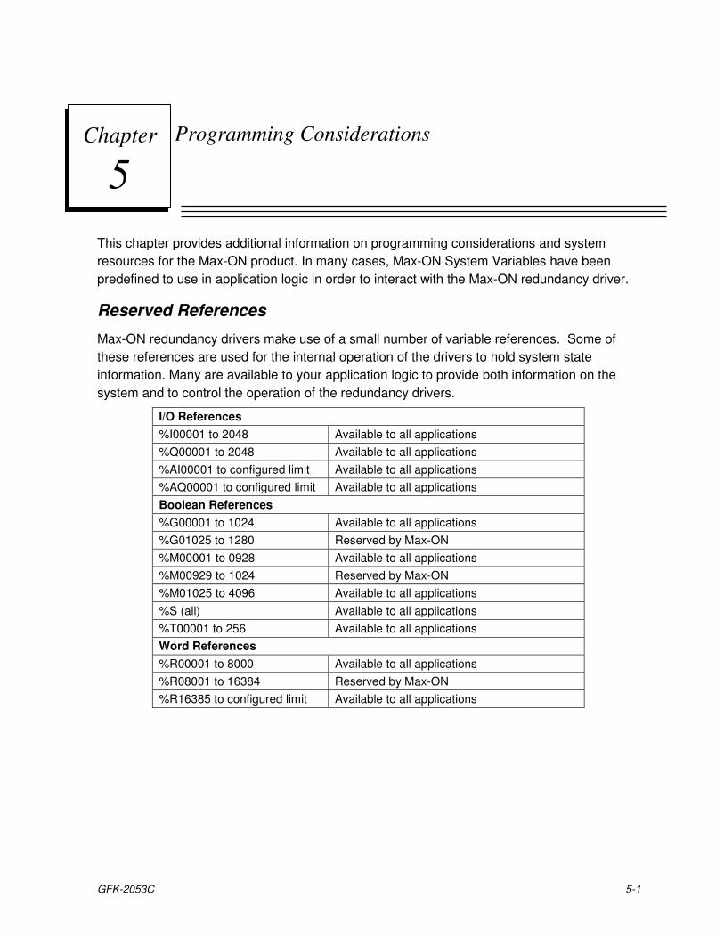
GFK-2053C 5-1
Programming Considerations
This chapter provides additional information on programming considerations and system
resources for the Max-ON product. In many cases, Max-ON System Variables have been
predefined to use in application logic in order to interact with the Max-ON redundancy driver.
Reserved References
Max-ON redundancy drivers make use of a small number of variable references. Some of
these references are used for the internal operation of the drivers to hold system state
information. Many are available to your application logic to provide both information on the
system and to control the operation of the redundancy drivers.
I/O References
%I00001 to 2048 Available to all applications
%Q00001 to 2048 Available to all applications
%AI00001 to configured limit Available to all applications
%AQ00001 to configured limit Available to all applications
Boolean References
%G00001 to 1024 Available to all applications
%G01025 to 1280 Reserved by Max-ON
%M00001 to 0928 Available to all applications
%M00929 to 1024 Reserved by Max-ON
%M01025 to 4096 Available to all applications
%S (all) Available to all applications
%T00001 to 256 Available to all applications
Word References
%R00001 to 8000 Available to all applications
%R08001 to 16384 Reserved by Max-ON
%R16385 to configured limit Available to all applications
Chapter
5
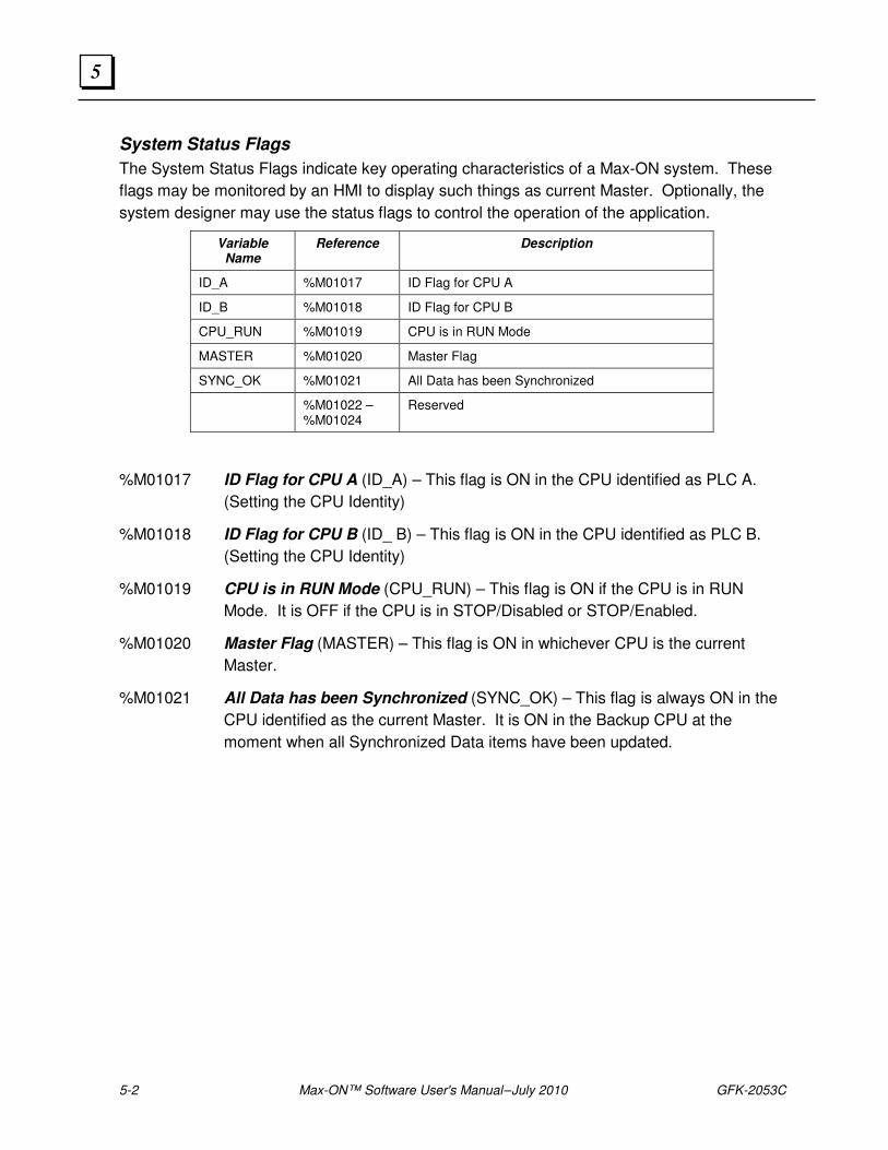
5-2 Max-ON™ Software User's Manual – July 2010 GFK-2053C
5
System Status Flags
The System Status Flags indicate key operating characteristics of a Max-ON system. These
flags may be monitored by an HMI to display such things as current Master. Optionally, the
system designer may use the status flags to control the operation of the application.
Variable Name
Reference Description
ID_A %M01017 ID Flag for CPU A
ID_B %M01018 ID Flag for CPU B
CPU_RUN %M01019 CPU is in RUN Mode
MASTER %M01020 Master Flag
SYNC_OK %M01021 All Data has been Synchronized
%M01022 –%M01024
Reserved
%M01017 ID Flag for CPU A (ID_A) – This flag is ON in the CPU identified as PLC A.
(Setting the CPU Identity)
%M01018 ID Flag for CPU B (ID_ B) – This flag is ON in the CPU identified as PLC B.
(Setting the CPU Identity)
%M01019 CPU is in RUN Mode (CPU_RUN) – This flag is ON if the CPU is in RUN
Mode. It is OFF if the CPU is in STOP/Disabled or STOP/Enabled.
%M01020 Master Flag (MASTER) – This flag is ON in whichever CPU is the current
Master.
%M01021 All Data has been Synchronized (SYNC_OK) – This flag is always ON in the
CPU identified as the current Master. It is ON in the Backup CPU at the
moment when all Synchronized Data items have been updated.
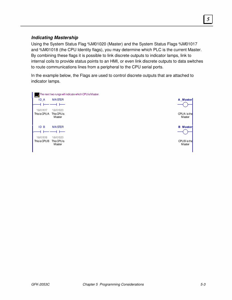
GFK-2053C Chapter 5 Programming Considerations 5-3
5
Indicating Mastership
Using the System Status Flag %M01020 (Master) and the System Status Flags %M01017
and %M01018 (the CPU Identity flags), you may determine which PLC is the current Master.
By combining these flags it is possible to link discrete outputs to indicator lamps, link to
internal coils to provide status points to an HMI, or even link discrete outputs to data switches
to route communications lines from a peripheral to the CPU serial ports.
In the example below, the Flags are used to control discrete outputs that are attached to
indicator lamps.
The next two rungs will indicate which CPU is Master.
ID_A
%M01017
This is CPU A
MASTER
%M01020
This CPU isMaster
A _M aster
CPU A is theMaster
ID_B
%M01018
This is CPU B
MASTER
%M01020
This CPU isMaster
B_M aster
CPU B is theMaster
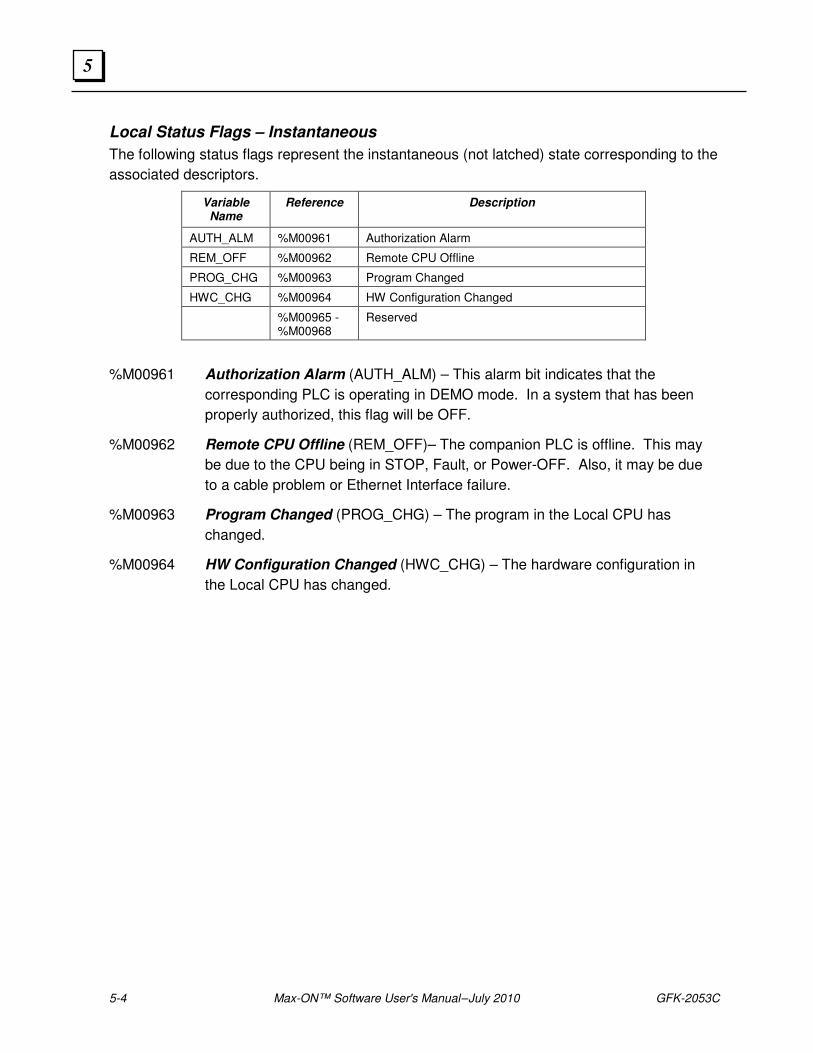
5-4 Max-ON™ Software User's Manual – July 2010 GFK-2053C
5
Local Status Flags – Instantaneous
The following status flags represent the instantaneous (not latched) state corresponding to the
associated descriptors.
Variable Name
Reference Description
AUTH_ALM %M00961 Authorization Alarm
REM_OFF %M00962 Remote CPU Offline
PROG_CHG %M00963 Program Changed
HWC_CHG %M00964 HW Configuration Changed
%M00965 - %M00968
Reserved
%M00961 Authorization Alarm (AUTH_ALM) – This alarm bit indicates that the
corresponding PLC is operating in DEMO mode. In a system that has been
properly authorized, this flag will be OFF.
%M00962 Remote CPU Offline (REM_OFF)– The companion PLC is offline. This may
be due to the CPU being in STOP, Fault, or Power-OFF. Also, it may be due
to a cable problem or Ethernet Interface failure.
%M00963 Program Changed (PROG_CHG) – The program in the Local CPU has
changed.
%M00964 HW Configuration Changed (HWC_CHG) – The hardware configuration in
the Local CPU has changed.
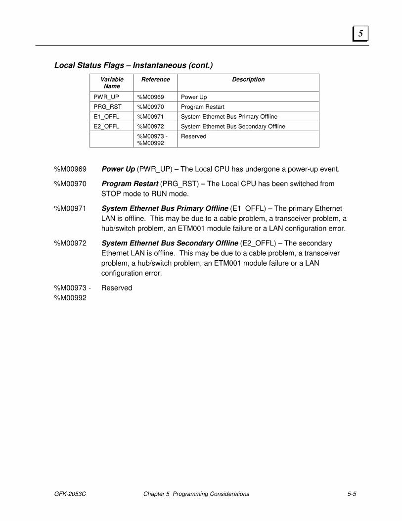
GFK-2053C Chapter 5 Programming Considerations 5-5
5
Local Status Flags – Instantaneous (cont.)
Variable Name
Reference Description
PWR_UP %M00969 Power Up
PRG_RST %M00970 Program Restart
E1_OFFL %M00971 System Ethernet Bus Primary Offline
E2_OFFL %M00972 System Ethernet Bus Secondary Offline
%M00973 -%M00992
Reserved
%M00969 Power Up (PWR_UP) – The Local CPU has undergone a power-up event.
%M00970 Program Restart (PRG_RST) – The Local CPU has been switched from
STOP mode to RUN mode.
%M00971 System Ethernet Bus Primary Offline (E1_OFFL) – The primary Ethernet
LAN is offline. This may be due to a cable problem, a transceiver problem, a
hub/switch problem, an ETM001 module failure or a LAN configuration error.
%M00972 System Ethernet Bus Secondary Offline (E2_OFFL) – The secondary
Ethernet LAN is offline. This may be due to a cable problem, a transceiver
problem, a hub/switch problem, an ETM001 module failure or a LAN
configuration error.
%M00973 - Reserved
%M00992
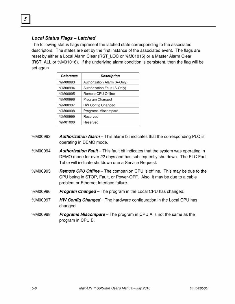
5-6 Max-ON™ Software User's Manual – July 2010 GFK-2053C
5
Local Status Flags – Latched
The following status flags represent the latched state corresponding to the associated
descriptors. The states are set by the first instance of the associated event. The flags are
reset by either a Local Alarm Clear (RST_LOC or %M01015) or a Master Alarm Clear
(RST_ALL or %M01016). If the underlying alarm condition is persistent, then the flag will be
set again.
Reference Description
%M00993 Authorization Alarm (A-Only)
%M00994 Authorization Fault (A-Only)
%M00995 Remote CPU Offline
%M00996 Program Changed
%M00997 HW Config Changed
%M00998 Programs Miscompare
%M00999 Reserved
%M01000 Reserved
%M00993 Authorization Alarm – This alarm bit indicates that the corresponding PLC is
operating in DEMO mode.
%M00994 Authorization Fault – This fault bit indicates that the system was operating in
DEMO mode for over 22 days and has subsequently shutdown. The PLC Fault
Table will indicate shutdown due a Service Request.
%M00995 Remote CPU Offline – The companion CPU is offline. This may be due to the
CPU being in STOP, Fault, or Power-OFF. Also, it may be due to a cable
problem or Ethernet Interface failure.
%M00996 Program Changed – The program in the Local CPU has changed.
%M00997 HW Config Changed – The hardware configuration in the Local CPU has
changed.
%M00998 Programs Miscompare – The program in CPU A is not the same as the
program in CPU B.
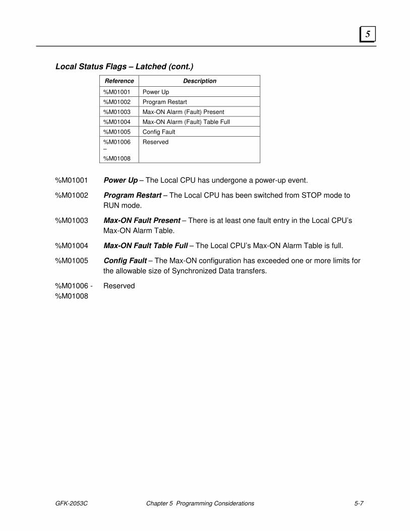
GFK-2053C Chapter 5 Programming Considerations 5-7
5
Local Status Flags – Latched (cont.)
Reference Description
%M01001 Power Up
%M01002 Program Restart
%M01003 Max-ON Alarm (Fault) Present
%M01004 Max-ON Alarm (Fault) Table Full
%M01005 Config Fault
%M01006 –
%M01008
Reserved
%M01001 Power Up – The Local CPU has undergone a power-up event.
%M01002 Program Restart – The Local CPU has been switched from STOP mode to
RUN mode.
%M01003 Max-ON Fault Present – There is at least one fault entry in the Local CPU’s
Max-ON Alarm Table.
%M01004 Max-ON Fault Table Full – The Local CPU’s Max-ON Alarm Table is full.
%M01005 Config Fault – The Max-ON configuration has exceeded one or more limits for
the allowable size of Synchronized Data transfers.
%M01006 - Reserved
%M01008
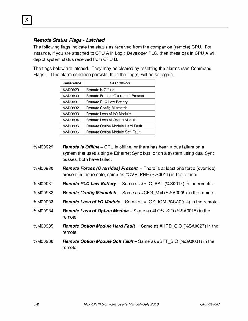
5-8 Max-ON™ Software User's Manual – July 2010 GFK-2053C
5
Remote Status Flags - Latched
The following flags indicate the status as received from the companion (remote) CPU. For
instance, if you are attached to CPU A in Logic Developer PLC, then these bits in CPU A will
depict system status received from CPU B.
The flags below are latched. They may be cleared by resetting the alarms (see Command
Flags). If the alarm condition persists, then the flag(s) will be set again.
Reference Description
%M00929 Remote is Offline
%M00930 Remote Forces (Overrides) Present
%M00931 Remote PLC Low Battery
%M00932 Remote Config Mismatch
%M00933 Remote Loss of I/O Module
%M00934 Remote Loss of Option Module
%M00935 Remote Option Module Hard Fault
%M00936 Remote Option Module Soft Fault
%M00929 Remote is Offline – CPU is offline, or there has been a bus failure on a
system that uses a single Ethernet Sync bus, or on a system using dual Sync
busses, both have failed.
%M00930 Remote Forces (Overrides) Present – There is at least one force (override)
present in the remote, same as #OVR_PRE (%S0011) in the remote.
%M00931 Remote PLC Low Battery – Same as #PLC_BAT (%S0014) in the remote.
%M00932 Remote Config Mismatch – Same as #CFG_MM (%SA0009) in the remote.
%M00933 Remote Loss of I/O Module – Same as #LOS_IOM (%SA0014) in the remote.
%M00934 Remote Loss of Option Module – Same as #LOS_SIO (%SA0015) in the
remote.
%M00935 Remote Option Module Hard Fault – Same as #HRD_SIO (%SA0027) in the
remote.
%M00936 Remote Option Module Soft Fault – Same as #SFT_SIO (%SA0031) in the
remote.
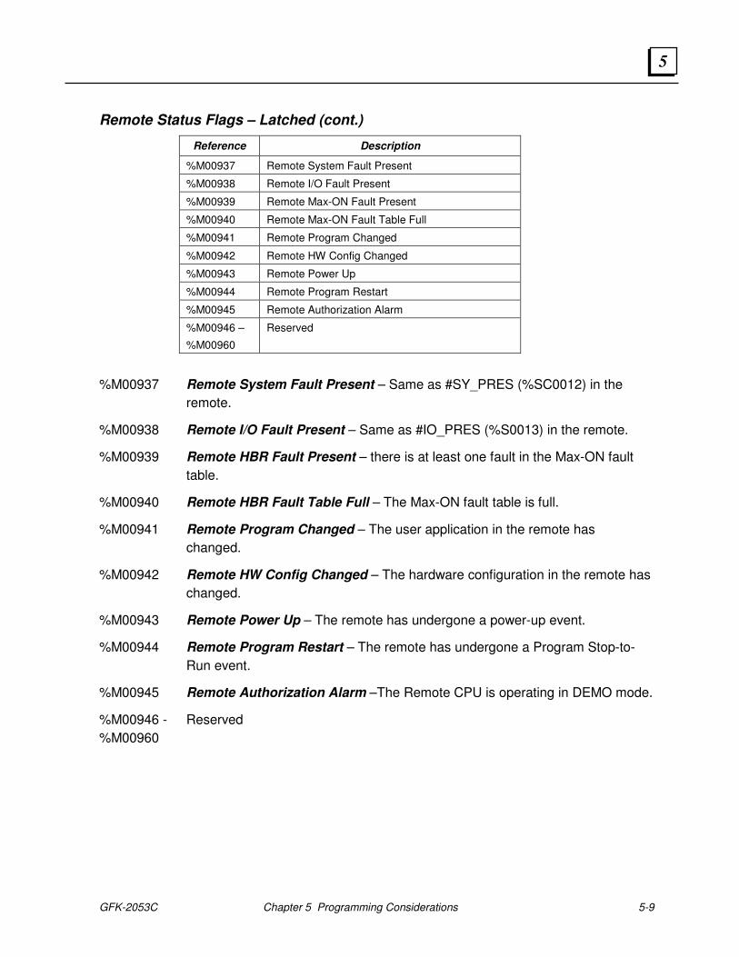
GFK-2053C Chapter 5 Programming Considerations 5-9
5
Remote Status Flags – Latched (cont.)
Reference Description
%M00937 Remote System Fault Present
%M00938 Remote I/O Fault Present
%M00939 Remote Max-ON Fault Present
%M00940 Remote Max-ON Fault Table Full
%M00941 Remote Program Changed
%M00942 Remote HW Config Changed
%M00943 Remote Power Up
%M00944 Remote Program Restart
%M00945 Remote Authorization Alarm
%M00946 –
%M00960
Reserved
%M00937 Remote System Fault Present – Same as #SY_PRES (%SC0012) in the
remote.
%M00938 Remote I/O Fault Present – Same as #IO_PRES (%S0013) in the remote.
%M00939 Remote HBR Fault Present – there is at least one fault in the Max-ON fault
table.
%M00940 Remote HBR Fault Table Full – The Max-ON fault table is full.
%M00941 Remote Program Changed – The user application in the remote has
changed.
%M00942 Remote HW Config Changed – The hardware configuration in the remote has
changed.
%M00943 Remote Power Up – The remote has undergone a power-up event.
%M00944 Remote Program Restart – The remote has undergone a Program Stop-to-
Run event.
%M00945 Remote Authorization Alarm –The Remote CPU is operating in DEMO mode.
%M00946 - Reserved
%M00960
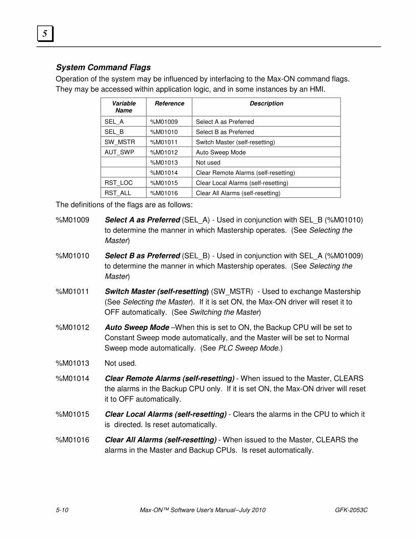
5-10 Max-ON™ Software User's Manual – July 2010 GFK-2053C
5
System Command Flags
Operation of the system may be influenced by interfacing to the Max-ON command flags.
They may be accessed within application logic, and in some instances by an HMI.
Variable Name
Reference Description
SEL_A %M01009 Select A as Preferred
SEL_B %M01010 Select B as Preferred
SW_MSTR %M01011 Switch Master (self-resetting)
AUT_SWP %M01012 Auto Sweep Mode
%M01013 Not used
%M01014 Clear Remote Alarms (self-resetting)
RST_LOC %M01015 Clear Local Alarms (self-resetting)
RST_ALL %M01016 Clear All Alarms (self-resetting)
The definitions of the flags are as follows:
%M01009 Select A as Preferred (SEL_A) - Used in conjunction with SEL_B (%M01010)
to determine the manner in which Mastership operates. (See Selecting the
Master)
%M01010 Select B as Preferred (SEL_B) - Used in conjunction with SEL_A (%M01009)
to determine the manner in which Mastership operates. (See Selecting the
Master)
%M01011 Switch Master (self-resetting) (SW_MSTR) - Used to exchange Mastership
(See Selecting the Master). If it is set ON, the Max-ON driver will reset it to
OFF automatically. (See Switching the Master)
%M01012 Auto Sweep Mode –When this is set to ON, the Backup CPU will be set to
Constant Sweep mode automatically, and the Master will be set to Normal
Sweep mode automatically. (See PLC Sweep Mode.)
%M01013 Not used.
%M01014 Clear Remote Alarms (self-resetting) - When issued to the Master, CLEARS
the alarms in the Backup CPU only. If it is set ON, the Max-ON driver will reset
it to OFF automatically.
%M01015 Clear Local Alarms (self-resetting) - Clears the alarms in the CPU to which it
is directed. Is reset automatically.
%M01016 Clear All Alarms (self-resetting) - When issued to the Master, CLEARS the
alarms in the Master and Backup CPUs. Is reset automatically.
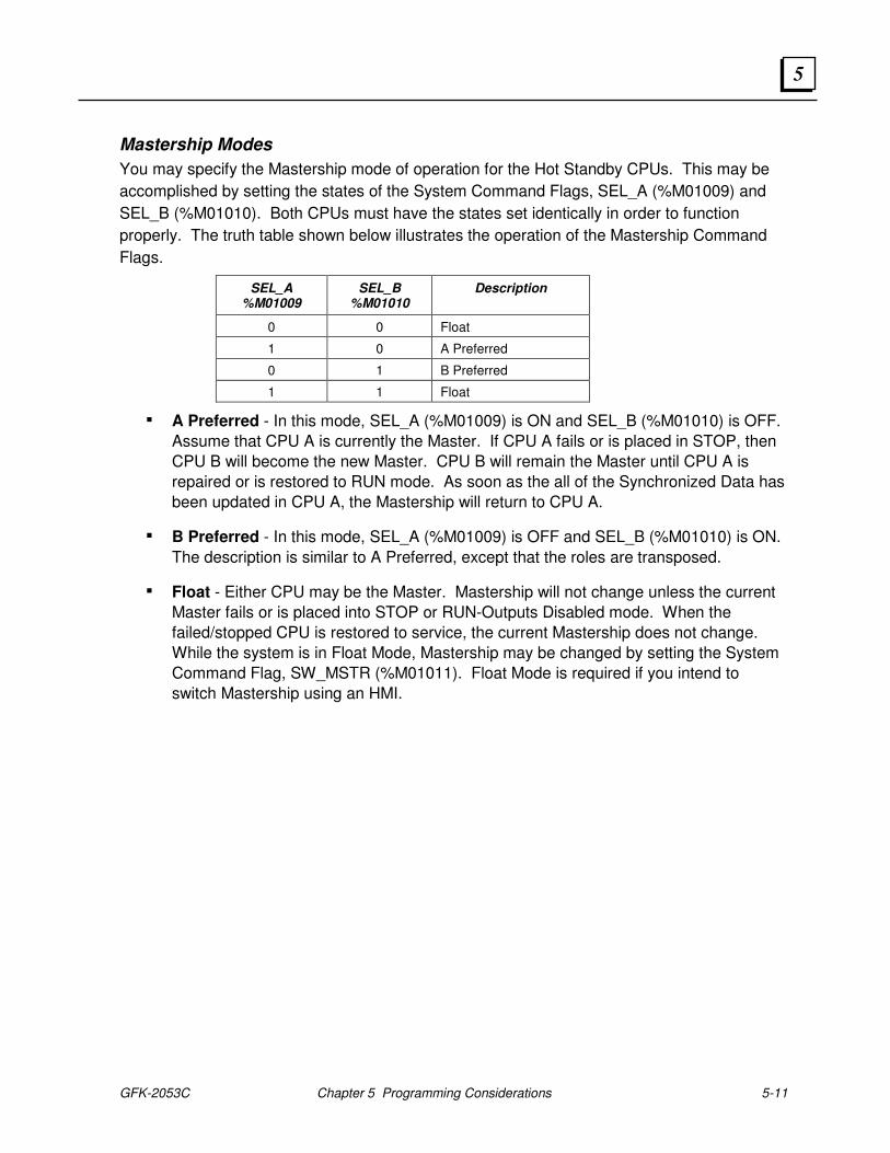
GFK-2053C Chapter 5 Programming Considerations 5-11
5
Mastership Modes
You may specify the Mastership mode of operation for the Hot Standby CPUs. This may be
accomplished by setting the states of the System Command Flags, SEL_A (%M01009) and
SEL_B (%M01010). Both CPUs must have the states set identically in order to function
properly. The truth table shown below illustrates the operation of the Mastership Command
Flags.
SEL_A %M01009
SEL_B %M01010
Description
0 0 Float
1 0 A Preferred
0 1 B Preferred
1 1 Float
▪ A Preferred - In this mode, SEL_A (%M01009) is ON and SEL_B (%M01010) is OFF.
Assume that CPU A is currently the Master. If CPU A fails or is placed in STOP, then
CPU B will become the new Master. CPU B will remain the Master until CPU A is
repaired or is restored to RUN mode. As soon as the all of the Synchronized Data has
been updated in CPU A, the Mastership will return to CPU A.
▪ B Preferred - In this mode, SEL_A (%M01009) is OFF and SEL_B (%M01010) is ON.
The description is similar to A Preferred, except that the roles are transposed.
▪ Float - Either CPU may be the Master. Mastership will not change unless the current
Master fails or is placed into STOP or RUN-Outputs Disabled mode. When the
failed/stopped CPU is restored to service, the current Mastership does not change.
While the system is in Float Mode, Mastership may be changed by setting the System
Command Flag, SW_MSTR (%M01011). Float Mode is required if you intend to
switch Mastership using an HMI.
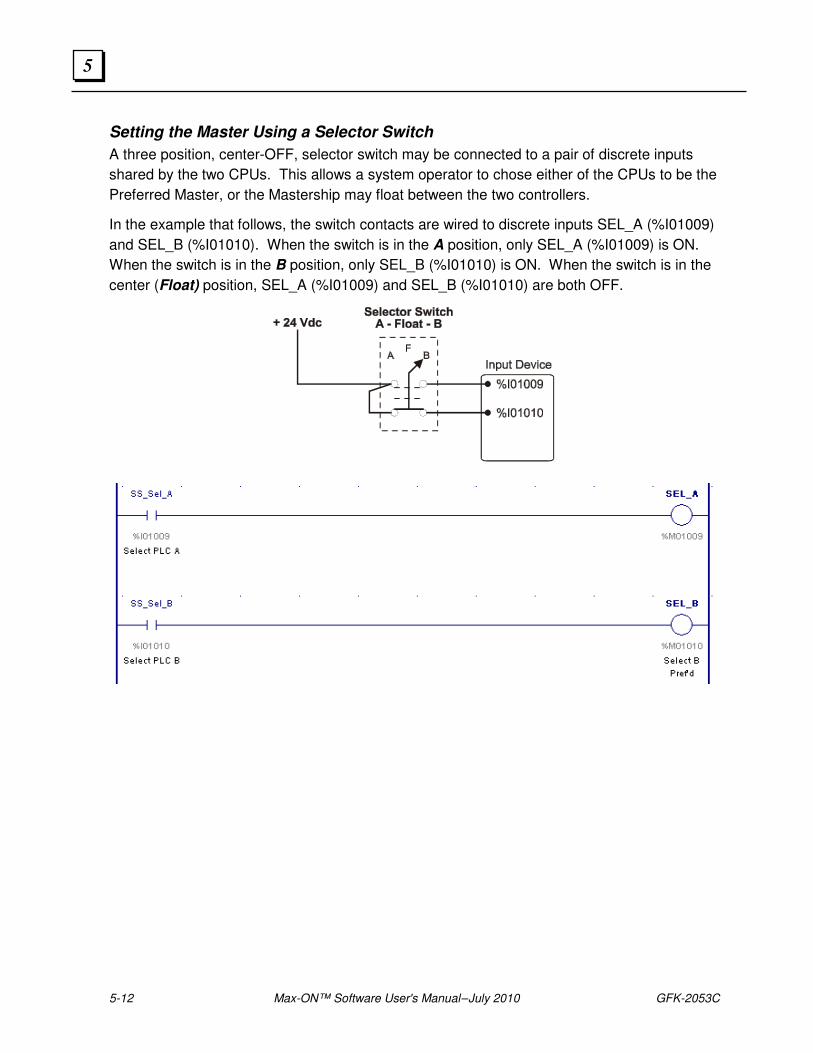
5-12 Max-ON™ Software User's Manual – July 2010 GFK-2053C
5
Setting the Master Using a Selector Switch
A three position, center-OFF, selector switch may be connected to a pair of discrete inputs
shared by the two CPUs. This allows a system operator to chose either of the CPUs to be the
Preferred Master, or the Mastership may float between the two controllers.
In the example that follows, the switch contacts are wired to discrete inputs SEL_A (%I01009)
and SEL_B (%I01010). When the switch is in the A position, only SEL_A (%I01009) is ON.
When the switch is in the B position, only SEL_B (%I01010) is ON. When the switch is in the
center (Float) position, SEL_A (%I01009) and SEL_B (%I01010) are both OFF.
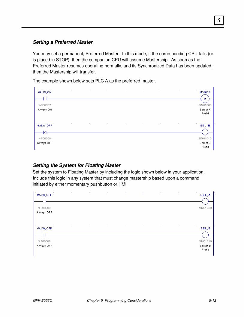
GFK-2053C Chapter 5 Programming Considerations 5-13
5
Setting a Preferred Master
You may set a permanent, Preferred Master. In this mode, if the corresponding CPU fails (or
is placed in STOP), then the companion CPU will assume Mastership. As soon as the
Preferred Master resumes operating normally, and its Synchronized Data has been updated,
then the Mastership will transfer.
The example shown below sets PLC A as the preferred master.
Setting the System for Floating Master
Set the system to Floating Master by including the logic shown below in your application.
Include this logic in any system that must change mastership based upon a command
initiated by either momentary pushbutton or HMI.
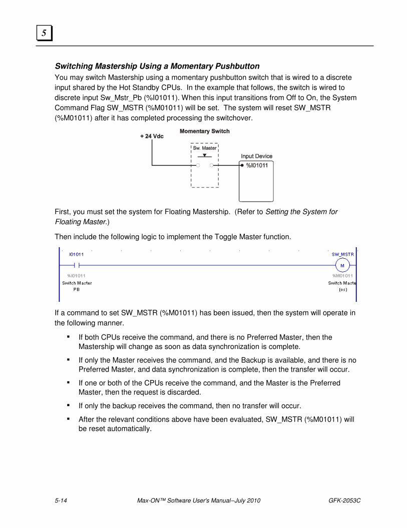
5-14 Max-ON™ Software User's Manual – July 2010 GFK-2053C
5
Switching Mastership Using a Momentary Pushbutton
You may switch Mastership using a momentary pushbutton switch that is wired to a discrete
input shared by the Hot Standby CPUs. In the example that follows, the switch is wired to
discrete input Sw_Mstr_Pb (%I01011). When this input transitions from Off to On, the System
Command Flag SW_MSTR (%M01011) will be set. The system will reset SW_MSTR
(%M01011) after it has completed processing the switchover.
First, you must set the system for Floating Mastership. (Refer to Setting the System for
Floating Master.)
Then include the following logic to implement the Toggle Master function.
If a command to set SW_MSTR (%M01011) has been issued, then the system will operate in
the following manner.
▪ If both CPUs receive the command, and there is no Preferred Master, then the
Mastership will change as soon as data synchronization is complete.
▪ If only the Master receives the command, and the Backup is available, and there is no
Preferred Master, and data synchronization is complete, then the transfer will occur.
▪ If one or both of the CPUs receive the command, and the Master is the Preferred
Master, then the request is discarded.
▪ If only the backup receives the command, then no transfer will occur.
▪ After the relevant conditions above have been evaluated, SW_MSTR (%M01011) will
be reset automatically.

GFK-2053C Chapter 5 Programming Considerations 5-15
5
Switching Mastership Using an HMI
In your HMI application, configure an operation that sets the command flag SW_MSTR
(%M01011) in the current Master CPU. The HMI should set SW_MSTR (%M01011) in each
PLC. This command will be executed in the current Master CPU, but will be ignored in the
current Backup CPU. Each CPU will reset the command automatically.
Assuming that there is no preferred Master set in either CPU, then the transfer will occur as
soon as data synchronization is complete. In most cases, this will happen immediately.
You must set the system for Floating Mastership. (Refer to Setting the System for Floating
Master.) No other logic is required.
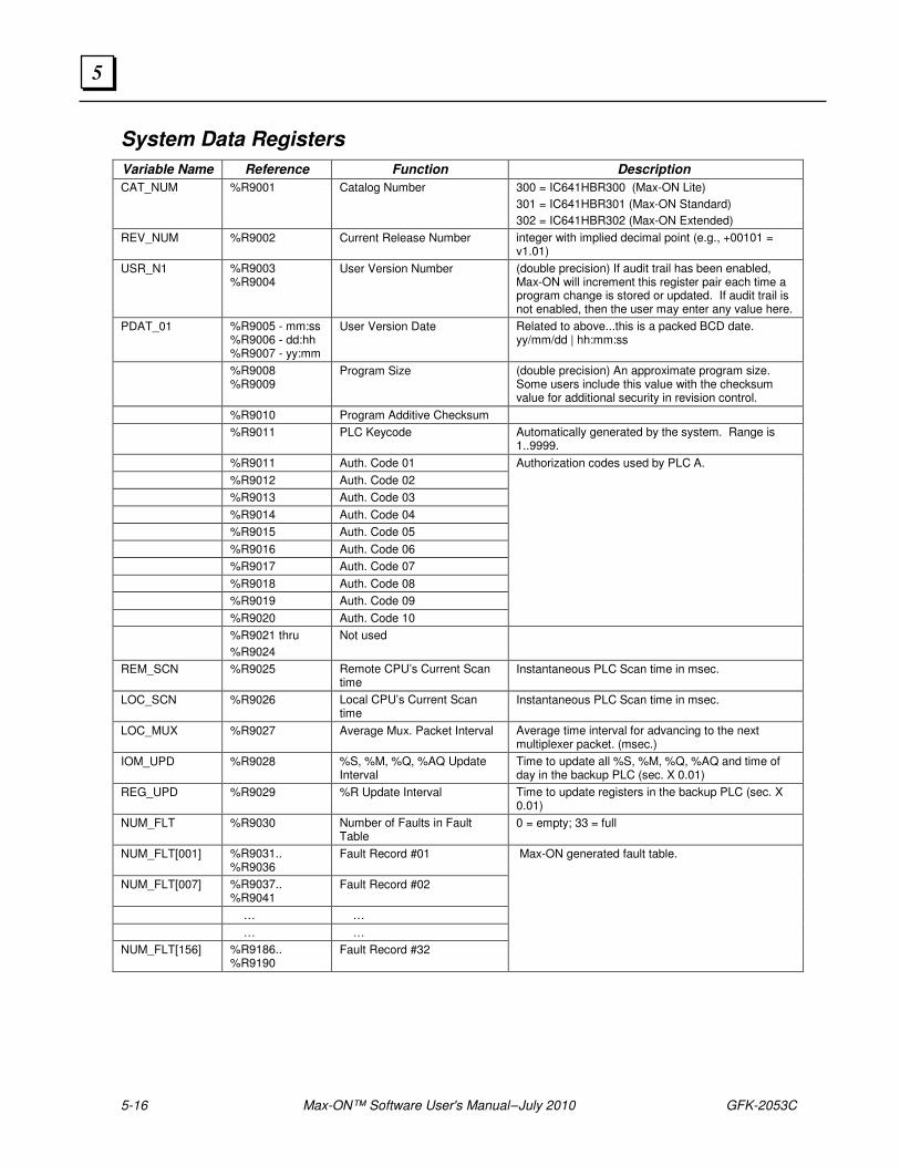
5-16 Max-ON™ Software User's Manual – July 2010 GFK-2053C
5
System Data Registers
Variable Name Reference Function Description
CAT_NUM %R9001 Catalog Number 300 = IC641HBR300 (Max-ON Lite)
301 = IC641HBR301 (Max-ON Standard)
302 = IC641HBR302 (Max-ON Extended)
REV_NUM %R9002 Current Release Number integer with implied decimal point (e.g., +00101 = v1.01)
USR_N1 %R9003 %R9004
User Version Number (double precision) If audit trail has been enabled, Max-ON will increment this register pair each time a program change is stored or updated. If audit trail is not enabled, then the user may enter any value here.
PDAT_01 %R9005 - mm:ss %R9006 - dd:hh %R9007 - yy:mm
User Version Date Related to above...this is a packed BCD date. yy/mm/dd | hh:mm:ss
%R9008 %R9009
Program Size (double precision) An approximate program size. Some users include this value with the checksum value for additional security in revision control.
%R9010 Program Additive Checksum
%R9011 PLC Keycode Automatically generated by the system. Range is 1..9999.
%R9011 Auth. Code 01 Authorization codes used by PLC A.
%R9012 Auth. Code 02
%R9013 Auth. Code 03
%R9014 Auth. Code 04
%R9015 Auth. Code 05
%R9016 Auth. Code 06
%R9017 Auth. Code 07
%R9018 Auth. Code 08
%R9019 Auth. Code 09
%R9020 Auth. Code 10
%R9021 thru
%R9024
Not used
REM_SCN %R9025 Remote CPU’s Current Scan time
Instantaneous PLC Scan time in msec.
LOC_SCN %R9026 Local CPU’s Current Scan time
Instantaneous PLC Scan time in msec.
LOC_MUX %R9027 Average Mux. Packet Interval Average time interval for advancing to the next multiplexer packet. (msec.)
IOM_UPD %R9028 %S, %M, %Q, %AQ Update Interval
Time to update all %S, %M, %Q, %AQ and time of day in the backup PLC (sec. X 0.01)
REG_UPD %R9029 %R Update Interval Time to update registers in the backup PLC (sec. X 0.01)
NUM_FLT %R9030 Number of Faults in Fault Table
0 = empty; 33 = full
NUM_FLT[001] %R9031.. %R9036
Fault Record #01 Max-ON generated fault table.
NUM_FLT[007] %R9037.. %R9041
Fault Record #02
… …
… …
NUM_FLT[156] %R9186.. %R9190
Fault Record #32
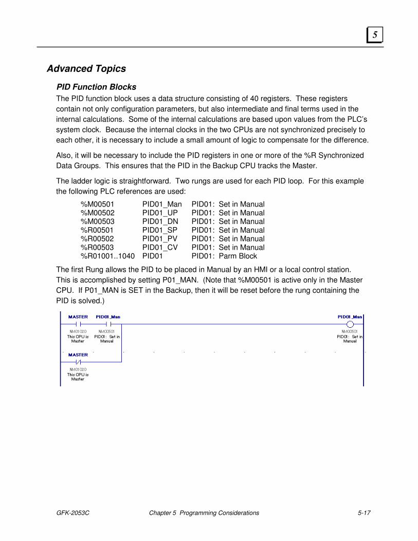
GFK-2053C Chapter 5 Programming Considerations 5-17
5
Advanced Topics
PID Function Blocks
The PID function block uses a data structure consisting of 40 registers. These registers
contain not only configuration parameters, but also intermediate and final terms used in the
internal calculations. Some of the internal calculations are based upon values from the PLC’s
system clock. Because the internal clocks in the two CPUs are not synchronized precisely to
each other, it is necessary to include a small amount of logic to compensate for the difference.
Also, it will be necessary to include the PID registers in one or more of the %R Synchronized
Data Groups. This ensures that the PID in the Backup CPU tracks the Master.
The ladder logic is straightforward. Two rungs are used for each PID loop. For this example
the following PLC references are used:
%M00501 PID01_Man PID01: Set in Manual %M00502 PID01_UP PID01: Set in Manual %M00503 PID01_DN PID01: Set in Manual %R00501 PID01_SP PID01: Set in Manual %R00502 PID01_PV PID01: Set in Manual %R00503 PID01_CV PID01: Set in Manual %R01001..1040 PID01 PID01: Parm Block
The first Rung allows the PID to be placed in Manual by an HMI or a local control station.
This is accomplished by setting P01_MAN. (Note that %M00501 is active only in the Master
CPU. If P01_MAN is SET in the Backup, then it will be reset before the rung containing the
PID is solved.)
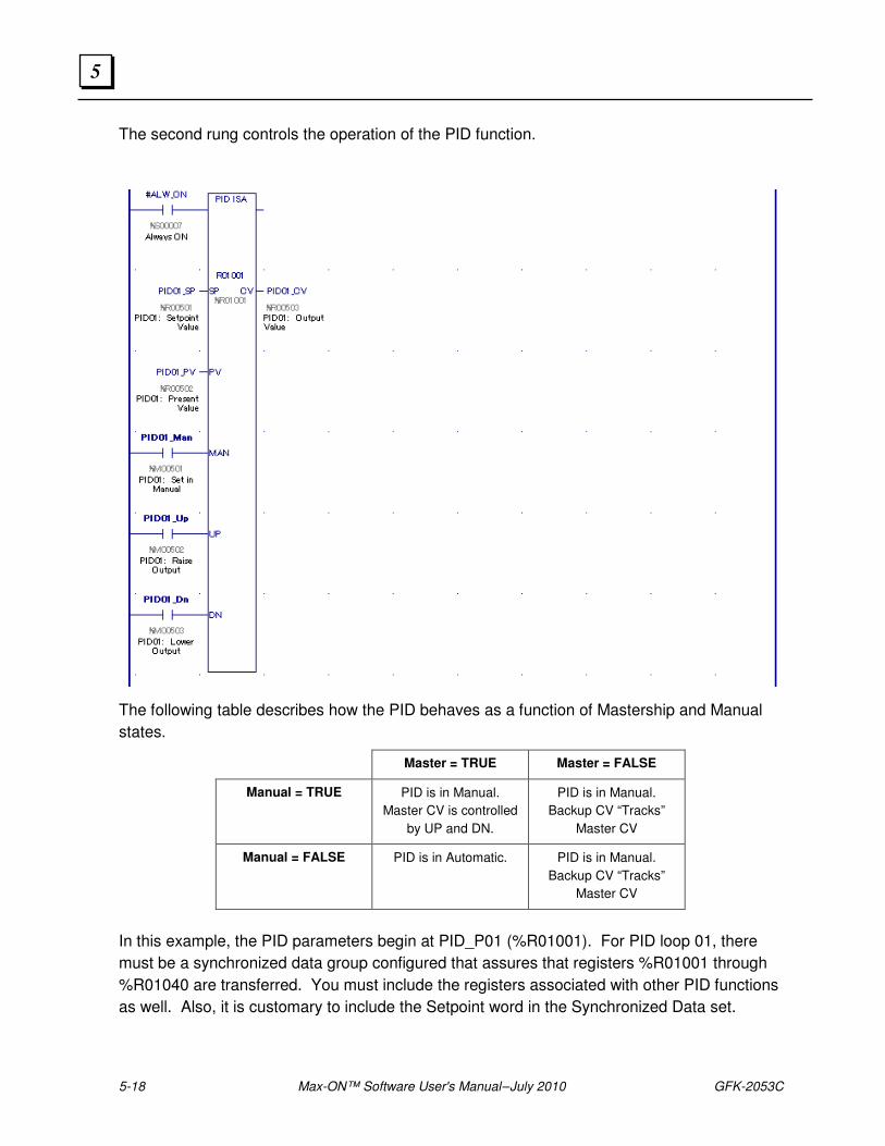
5-18 Max-ON™ Software User's Manual – July 2010 GFK-2053C
5
The second rung controls the operation of the PID function.
The following table describes how the PID behaves as a function of Mastership and Manual
states.
Master = TRUE Master = FALSE
Manual = TRUE PID is in Manual.
Master CV is controlled
by UP and DN.
PID is in Manual.
Backup CV “Tracks”
Master CV
Manual = FALSE PID is in Automatic. PID is in Manual.
Backup CV “Tracks”
Master CV
In this example, the PID parameters begin at PID_P01 (%R01001). For PID loop 01, there
must be a synchronized data group configured that assures that registers %R01001 through
%R01040 are transferred. You must include the registers associated with other PID functions
as well. Also, it is customary to include the Setpoint word in the Synchronized Data set.
GFK-2053C Chapter 5 Programming Considerations 5-19
5
User-Defined Alarms
The user may post self-defined faults from within the application by performing the following
steps.
Note: User defined Alarms are not available in this version the Max-ON VIEW Diagnostic
Tool.
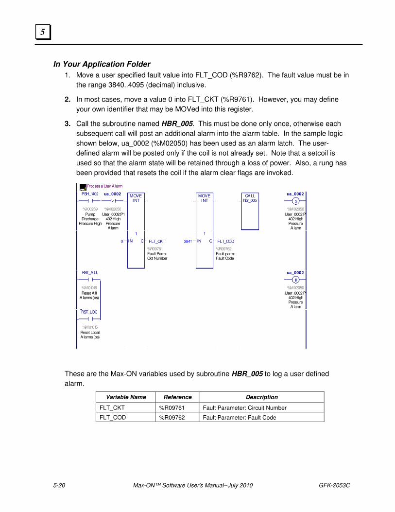
5-20 Max-ON™ Software User's Manual – July 2010 GFK-2053C
5
In Your Application Folder
1. Move a user specified fault value into FLT_COD (%R9762). The fault value must be in
the range 3840..4095 (decimal) inclusive.
2. In most cases, move a value 0 into FLT_CKT (%R9761). However, you may define
your own identifier that may be MOVed into this register.
3. Call the subroutine named HBR_005. This must be done only once, otherwise each
subsequent call will post an additional alarm into the alarm table. In the sample logic
shown below, ua_0002 (%M02050) has been used as an alarm latch. The user-
defined alarm will be posted only if the coil is not already set. Note that a setcoil is
used so that the alarm state will be retained through a loss of power. Also, a rung has
been provided that resets the coil if the alarm clear flags are invoked.
Process a User A larm
PSH_1402
%I00259
PumpDischarge
Pressure High
ua_0002
%M02050
User_0002:P1402 HighPressureA larm
MOVEINT
MOVEINT
CALLhbr_005
ua_0002
%M02050
User_0002:P1402 HighPressureA larm
0
1
IN Q FLT_CKT
%R09761Fault Parm: Ckt Number
3841
1
IN Q FLT_COD
%R09762Fault parm: Fault Code
RST_ALL
%M01016
Reset A llA larms (os)
ua_0002
%M02050
User_0002:P1402 HighPressureA larm
RST_LOC
%M01015
Reset LocalA larms (os)
These are the Max-ON variables used by subroutine HBR_005 to log a user defined
alarm.
Variable Name Reference Description
FLT_CKT %R09761 Fault Parameter: Circuit Number
FLT_COD %R09762 Fault Parameter: Fault Code
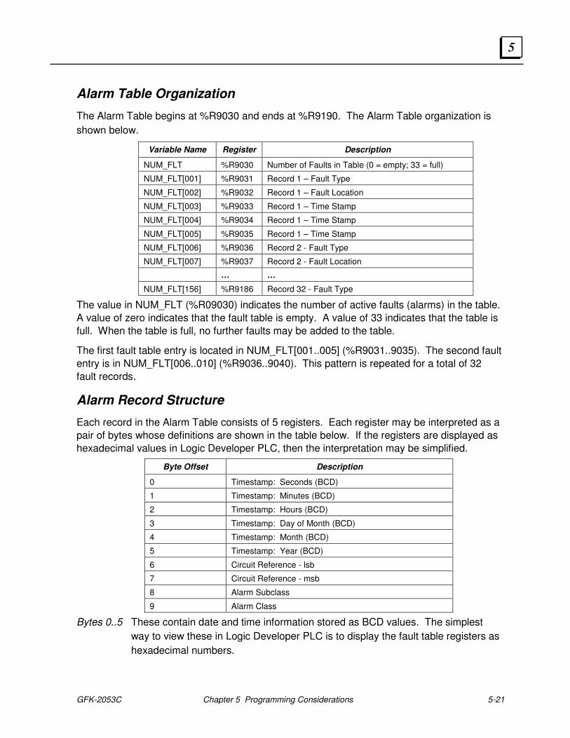
GFK-2053C Chapter 5 Programming Considerations 5-21
5
Alarm Table Organization
The Alarm Table begins at %R9030 and ends at %R9190. The Alarm Table organization is
shown below.
Variable Name Register Description
NUM_FLT %R9030 Number of Faults in Table (0 = empty; 33 = full)
NUM_FLT[001] %R9031 Record 1 – Fault Type
NUM_FLT[002] %R9032 Record 1 – Fault Location
NUM_FLT[003] %R9033 Record 1 – Time Stamp
NUM_FLT[004] %R9034 Record 1 – Time Stamp
NUM_FLT[005] %R9035 Record 1 – Time Stamp
NUM_FLT[006] %R9036 Record 2 - Fault Type
NUM_FLT[007] %R9037 Record 2 - Fault Location
… …
NUM_FLT[156] %R9186 Record 32 - Fault Type
The value in NUM_FLT (%R09030) indicates the number of active faults (alarms) in the table.
A value of zero indicates that the fault table is empty. A value of 33 indicates that the table is
full. When the table is full, no further faults may be added to the table.
The first fault table entry is located in NUM_FLT[001..005] (%R9031..9035). The second fault
entry is in NUM_FLT[006..010] (%R9036..9040). This pattern is repeated for a total of 32
fault records.
Alarm Record Structure
Each record in the Alarm Table consists of 5 registers. Each register may be interpreted as a
pair of bytes whose definitions are shown in the table below. If the registers are displayed as
hexadecimal values in Logic Developer PLC, then the interpretation may be simplified.
Byte Offset Description
0 Timestamp: Seconds (BCD)
1 Timestamp: Minutes (BCD)
2 Timestamp: Hours (BCD)
3 Timestamp: Day of Month (BCD)
4 Timestamp: Month (BCD)
5 Timestamp: Year (BCD)
6 Circuit Reference - lsb
7 Circuit Reference - msb
8 Alarm Subclass
9 Alarm Class
Bytes 0..5 These contain date and time information stored as BCD values. The simplest
way to view these in Logic Developer PLC is to display the fault table registers as
hexadecimal numbers.
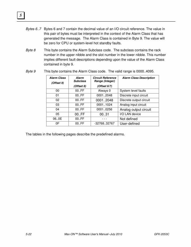
5-22 Max-ON™ Software User's Manual – July 2010 GFK-2053C
5
Bytes 6..7 Bytes 6 and 7 contain the decimal value of an I/O circuit reference. The value in
this pair of bytes must be interpreted in the context of the Alarm Class that has
generated the message. The Alarm Class is contained in Byte 9. The value will
be zero for CPU or system-level hot standby faults.
Byte 8 This byte contains the Alarm Subclass code. The subclass contains the rack
number in the upper nibble and the slot number in the lower nibble. This number
implies different fault descriptions depending upon the value of the Alarm Class
contained in byte 9.
Byte 9 This byte contains the Alarm Class code. The valid range is 0000..4095.
Alarm Class
(Offset 9)
Alarm Subclass
(Offset 8)
Circuit Reference Range (Integer)
(Offset 6/7)
Alarm Class Description
00 00..FF Always 0 System level faults
01 00..FF 0001..2048 Discrete input circuit
02 00..FF 0001..2048 Discrete output circuit
03 00..FF 0001..1024 Analog input circuit
04 00..FF 0001..0256 Analog output circuit
05 00..FF 00..31 I/O LAN device
06..0E 00..FF - - - Not defined
0F 00..FF -32768..32767 User-defined
The tables in the following pages describe the predefined alarms.
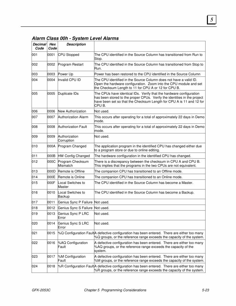
GFK-2053C Chapter 5 Programming Considerations 5-23
5
Alarm Class 00h - System Level Alarms
Decimal Code
Hex Code
Description
001 0001 CPU Stopped The CPU identified in the Source Column has transitioned from Run to Stop.
002 0002 Program Restart The CPU identified in the Source Column has transitioned from Stop to Run.
003 0003 Power Up Power has been restored to the CPU identified in the Source Column
004 0004 Invalid CPU ID The CPU identified in the Source Column does not have a valid ID. Open the hardware configuration. Zoom into the CPU module and set the Checksum Length to 11 for CPU A or 12 for CPU B.
005 0005 Duplicate IDs The CPUs have identical IDs. Verify that the hardware configuration has been stored to the proper CPUs. Verify the identities in the project have been set so that the Checksum Length for CPU A is 11 and 12 for CPU B.
006 0006 New Authorization Not used.
007 0007 Authorization Alarm This occurs after operating for a total of approximately 22 days in Demo mode.
008 0008 Authorization Fault This occurs after operating for a total of approximately 22 days in Demo mode.
009 0009 Authorization Corruption
Not used.
010 000A Program Changed The application program in the identified CPU has changed either due to a program store or due to online editing.
011 000B HW Config Changed The hardware configuration in the identified CPU has changed.
012 000C Program Checksum Mismatch
There is a discrepancy between the checksum in CPU A and CPU B. This implies that the programs in the two CPUs are not equivalent.
013 000D Remote is Offline The companion CPU has transitioned to an Offline mode.
014 000E Remote is Online The companion CPU has transitioned to an Online mode.
015 000F Local Switches to Master
The CPU identified in the Source Column has become a Master.
016 0010 Local Switches to Backup
The CPU identified in the Source Column has become a Backup.
017 0011 Genius Sync P Failure Not used.
018 0012 Genius Sync S Failure Not used.
019 0013 Genius Sync P LRC Error
Not used.
020 0014 Genius Sync S LRC Error
Not used.
021 0015 %Q Configuration Fault A defective configuration has been entered. There are either too many %Q groups, or the reference range exceeds the capacity of the system.
022 0016 %AQ Configuration Fault
A defective configuration has been entered. There are either too many %AQ groups, or the reference range exceeds the capacity of the system.
023 0017 %M Configuration Fault
A defective configuration has been entered. There are either too many %M groups, or the reference range exceeds the capacity of the system.
024 0018 %R Configuration Fault A defective configuration has been entered. There are either too many %R groups, or the reference range exceeds the capacity of the system.

5-24 Max-ON™ Software User's Manual – July 2010 GFK-2053C
5
Decimal Code
Hex Code
Description
025 0019 Corrupted Config A defective configuration has been entered.
026 001A Ethernet Synchronization Primary Failure
The System’s primary Ethernet LAN has failed. CPU A and CPU B are unable to transfer Synchronized Data via the primary Ethernet LAN.
027 001B Ethernet Synchronization Secondary Failure
The System’s secondary Ethernet LAN has failed. CPU A and CPU B are unable to transfer Synchronized Data via the secondary Ethernet LAN.
028 001C Illegal Mastership State There are either two Masters or two Backups in operation.
029 001D Not used
… … …
032 0020 Not used
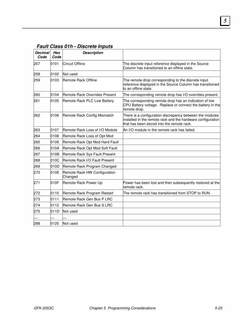
GFK-2053C Chapter 5 Programming Considerations 5-25
5
Fault Class 01h - Discrete Inputs
Decimal Code
Hex Code
Description
257 0101 Circuit Offline The discrete input reference displayed in the Source Column has transitioned to an offline state.
258 0102 Not used
259 0103 Remote Rack Offline The remote drop corresponding to the discrete input reference displayed in the Source Column has transitioned to an offline state.
260 0104 Remote Rack Overrides Present The corresponding remote drop has I/O overrides present.
261 0105 Remote Rack PLC Low Battery The corresponding remote drop has an indication of low CPU Battery voltage. Replace or connect the battery in the remote drop.
262 0106 Remote Rack Config Mismatch There is a configuration discrepancy between the modules installed in the remote rack and the hardware configuration that has been stored into the remote rack.
263 0107 Remote Rack Loss of I/O Module An I/O module in the remote rack has failed.
264 0108 Remote Rack Loss of Opt Mod
265 0109 Remote Rack Opt Mod Hard Fault
266 010A Remote Rack Opt Mod Soft Fault
267 010B Remote Rack Sys Fault Present
268 010C Remote Rack I/O Fault Present
269 010D Remote Rack Program Changed
270 010E Remote Rack HW Configuration Changed
271 010F Remote Rack Power Up Power has been lost and then subsequently restored at the remote rack.
272 0110 Remote Rack Program Restart The remote rack has transitioned from STOP to RUN.
273 0111 Remote Rack Gen Bus P LRC
274 0112 Remote Rack Gen Bus S LRC
275 011D Not used
… … …
288 0120 Not used
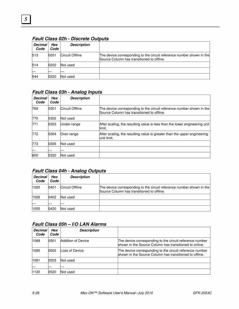
5-26 Max-ON™ Software User's Manual – July 2010 GFK-2053C
5
Fault Class 02h - Discrete Outputs
Decimal Code
Hex Code
Description
513 0201 Circuit Offline The device corresponding to the circuit reference number shown in the Source Column has transitioned to offline.
514 0202 Not used
… … …
544 0220 Not used
Fault Class 03h - Analog Inputs
Decimal Code
Hex Code
Description
769 0301 Circuit Offline The device corresponding to the circuit reference number shown in the Source Column has transitioned to offline.
770 0302 Not used
771 0303 Under-range After scaling, the resulting value is less than the lower engineering unit limit.
772 0304 Over-range After scaling, the resulting value is greater than the upper engineering unit limit.
773 0305 Not used
… … …
800 0320 Not used
Fault Class 04h - Analog Outputs
Decimal Code
Hex Code
Description
1025 0401 Circuit Offline The device corresponding to the circuit reference number shown in the Source Column has transitioned to offline.
1026 0402 Not used
… … …
1055 0420 Not used
Fault Class 05h – I/O LAN Alarms
Decimal Code
Hex Code
Description
1089 0501 Addition of Device The device corresponding to the circuit reference number shown in the Source Column has transitioned to online.
1090 0502 Loss of Device The device corresponding to the circuit reference number shown in the Source Column has transitioned to offline.
1091 0503 Not used
… … …
1120 0520 Not used

GFK-2053C Chapter 5 Programming Considerations 5-27
5

5-28 Max-ON™ Software User's Manual – July 2010 GFK-2053C
5
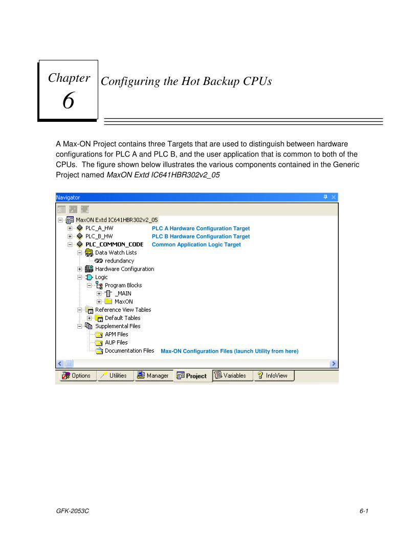
GFK-2053C 6-1
Configuring the Hot Backup CPUs
A Max-ON Project contains three Targets that are used to distinguish between hardware
configurations for PLC A and PLC B, and the user application that is common to both of the
CPUs. The figure shown below illustrates the various components contained in the Generic
Project named MaxON Extd IC641HBR302v2_05
Chapter
6
PLC A Hardware Configuration Target
PLC B Hardware Configuration Target
Common Application Logic Target
Max-ON Configuration Files (launch Utility from here)
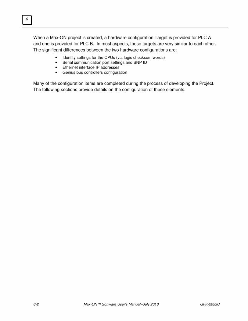
6-2 Max-ON™ Software User's Manual – July 2010 GFK-2053C
6
When a Max-ON project is created, a hardware configuration Target is provided for PLC A
and one is provided for PLC B. In most aspects, these targets are very similar to each other.
The significant differences between the two hardware configurations are:
• Identity settings for the CPUs (via logic checksum words)
• Serial communication port settings and SNP ID
• Ethernet interface IP addresses
• Genius bus controllers configuration
Many of the configuration items are completed during the process of developing the Project.
The following sections provide details on the configuration of these elements.
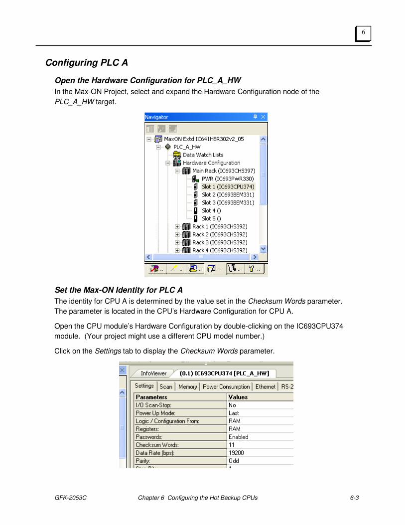
GFK-2053C Chapter 6 Configuring the Hot Backup CPUs 6-3
6
Configuring PLC A
Open the Hardware Configuration for PLC_A_HW
In the Max-ON Project, select and expand the Hardware Configuration node of the
PLC_A_HW target.
Set the Max-ON Identity for PLC A
The identity for CPU A is determined by the value set in the Checksum Words parameter.
The parameter is located in the CPU’s Hardware Configuration for CPU A.
Open the CPU module’s Hardware Configuration by double-clicking on the IC693CPU374
module. (Your project might use a different CPU model number.)
Click on the Settings tab to display the Checksum Words parameter.
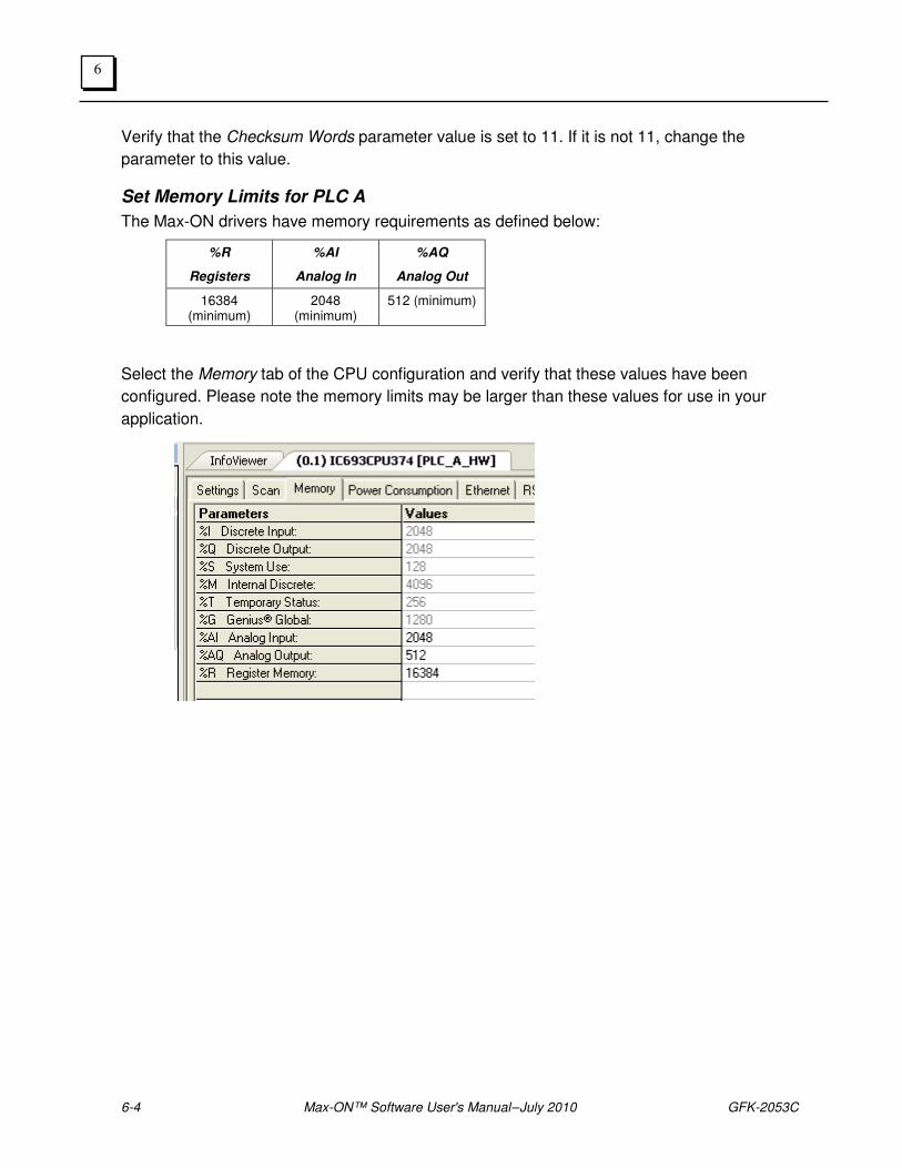
6-4 Max-ON™ Software User's Manual – July 2010 GFK-2053C
6
Verify that the Checksum Words parameter value is set to 11. If it is not 11, change the
parameter to this value.
Set Memory Limits for PLC A
The Max-ON drivers have memory requirements as defined below:
%R
Registers
%AI
Analog In
%AQ
Analog Out
16384 (minimum)
2048 (minimum)
512 (minimum)
Select the Memory tab of the CPU configuration and verify that these values have been
configured. Please note the memory limits may be larger than these values for use in your
application.
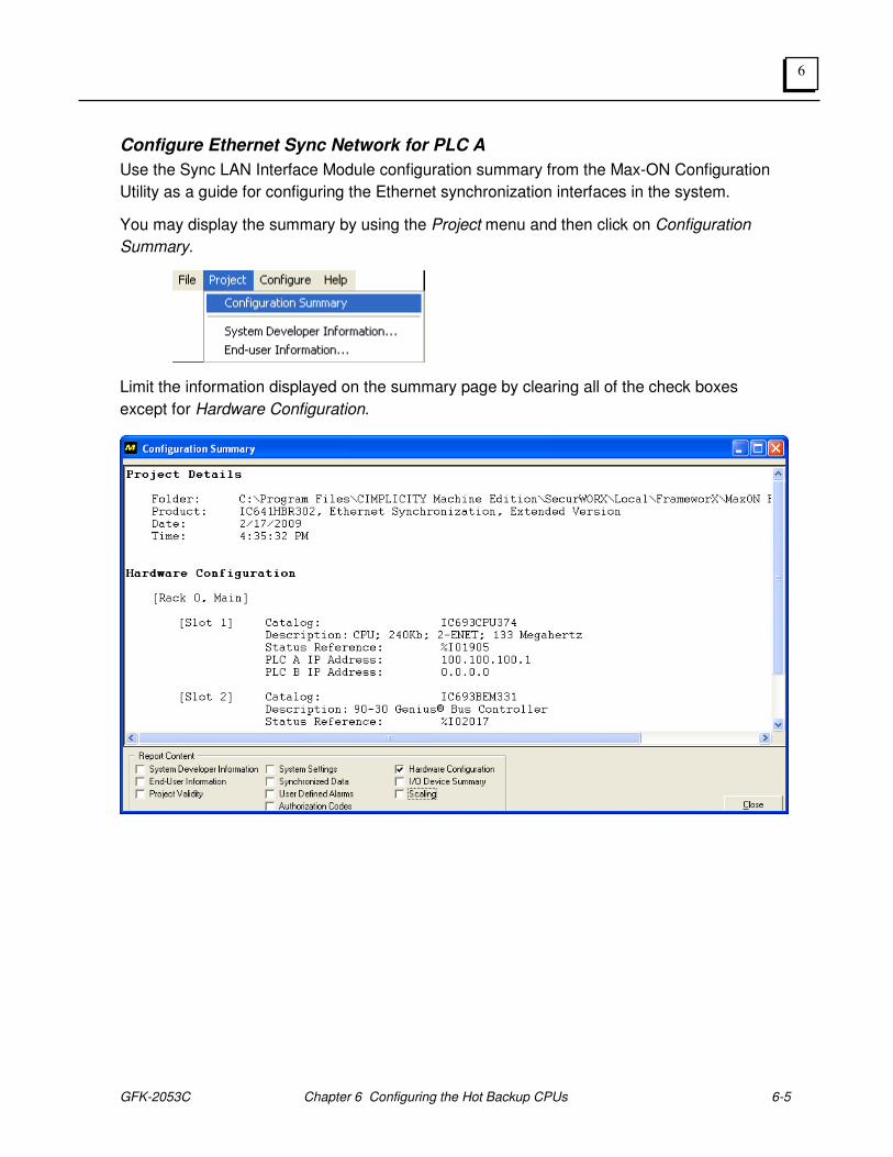
GFK-2053C Chapter 6 Configuring the Hot Backup CPUs 6-5
6
Configure Ethernet Sync Network for PLC A
Use the Sync LAN Interface Module configuration summary from the Max-ON Configuration
Utility as a guide for configuring the Ethernet synchronization interfaces in the system.
You may display the summary by using the Project menu and then click on Configuration
Summary.
Limit the information displayed on the summary page by clearing all of the check boxes
except for Hardware Configuration.
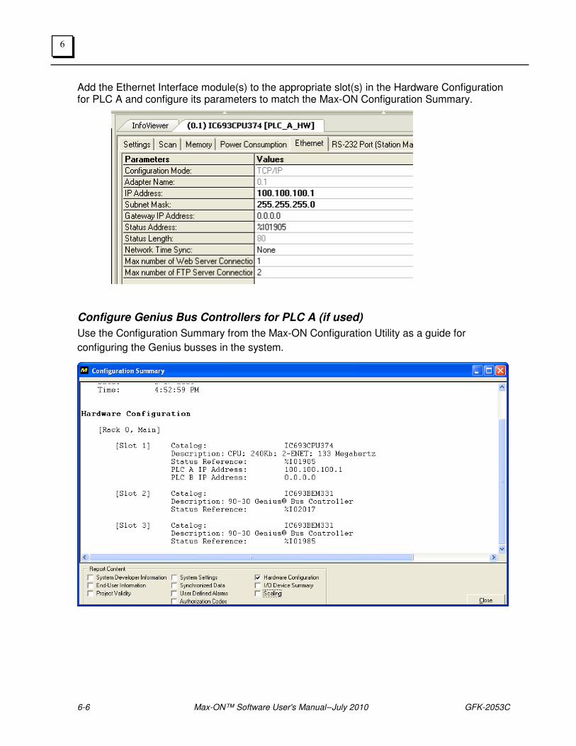
6-6 Max-ON™ Software User's Manual – July 2010 GFK-2053C
6
Add the Ethernet Interface module(s) to the appropriate slot(s) in the Hardware Configuration for PLC A and configure its parameters to match the Max-ON Configuration Summary.
Configure Genius Bus Controllers for PLC A (if used)
Use the Configuration Summary from the Max-ON Configuration Utility as a guide for
configuring the Genius busses in the system.
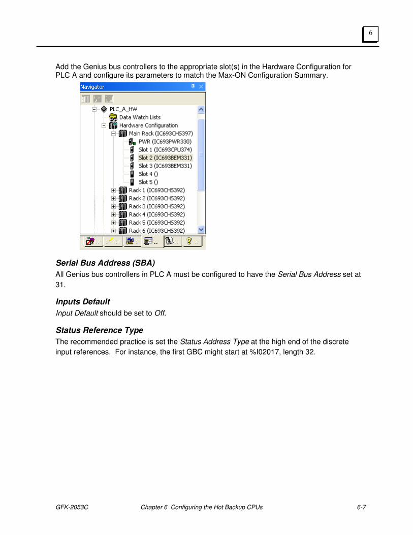
GFK-2053C Chapter 6 Configuring the Hot Backup CPUs 6-7
6
Add the Genius bus controllers to the appropriate slot(s) in the Hardware Configuration for PLC A and configure its parameters to match the Max-ON Configuration Summary.
Serial Bus Address (SBA)
All Genius bus controllers in PLC A must be configured to have the Serial Bus Address set at
31.
Inputs Default
Input Default should be set to Off.
Status Reference Type
The recommended practice is set the Status Address Type at the high end of the discrete
input references. For instance, the first GBC might start at %I02017, length 32.
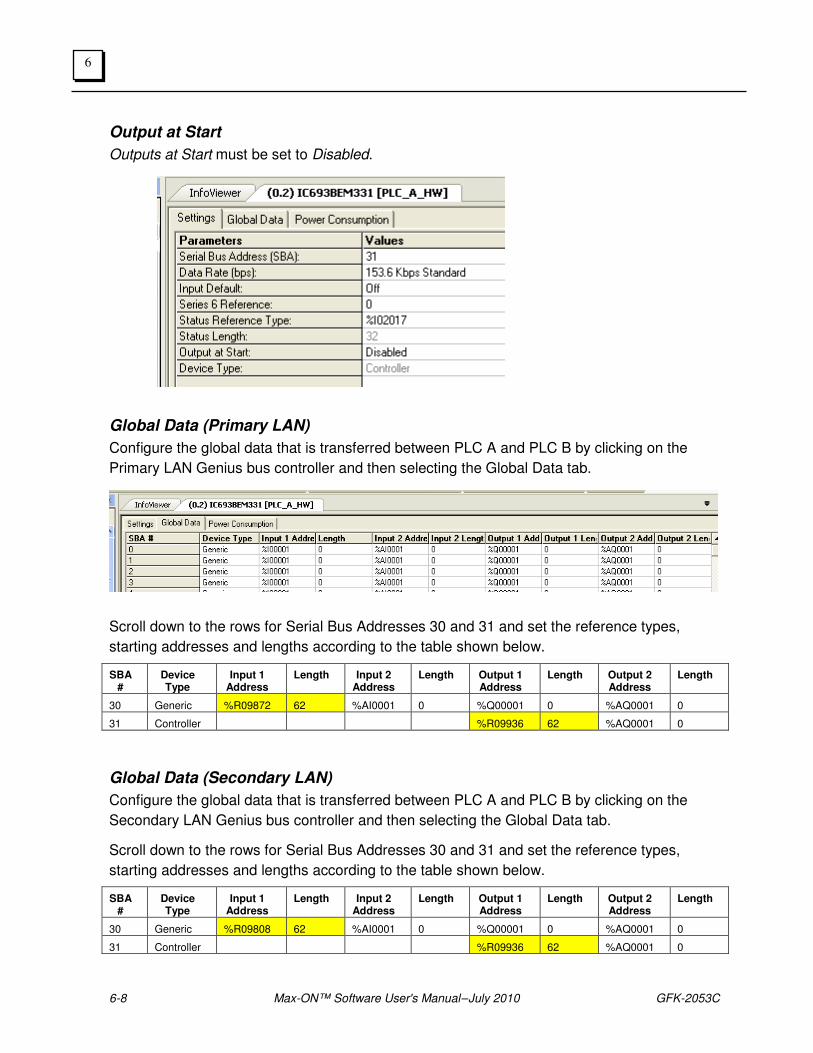
6-8 Max-ON™ Software User's Manual – July 2010 GFK-2053C
6
Output at Start
Outputs at Start must be set to Disabled.
Global Data (Primary LAN)
Configure the global data that is transferred between PLC A and PLC B by clicking on the
Primary LAN Genius bus controller and then selecting the Global Data tab.
Scroll down to the rows for Serial Bus Addresses 30 and 31 and set the reference types,
starting addresses and lengths according to the table shown below.
SBA #
Device Type
Input 1 Address
Length Input 2 Address
Length Output 1 Address
Length Output 2 Address
Length
30 Generic %R09872 62 %AI0001 0 %Q00001 0 %AQ0001 0
31 Controller %R09936 62 %AQ0001 0
Global Data (Secondary LAN)
Configure the global data that is transferred between PLC A and PLC B by clicking on the
Secondary LAN Genius bus controller and then selecting the Global Data tab.
Scroll down to the rows for Serial Bus Addresses 30 and 31 and set the reference types,
starting addresses and lengths according to the table shown below.
SBA #
Device Type
Input 1 Address
Length Input 2 Address
Length Output 1 Address
Length Output 2 Address
Length
30 Generic %R09808 62 %AI0001 0 %Q00001 0 %AQ0001 0
31 Controller %R09936 62 %AQ0001 0
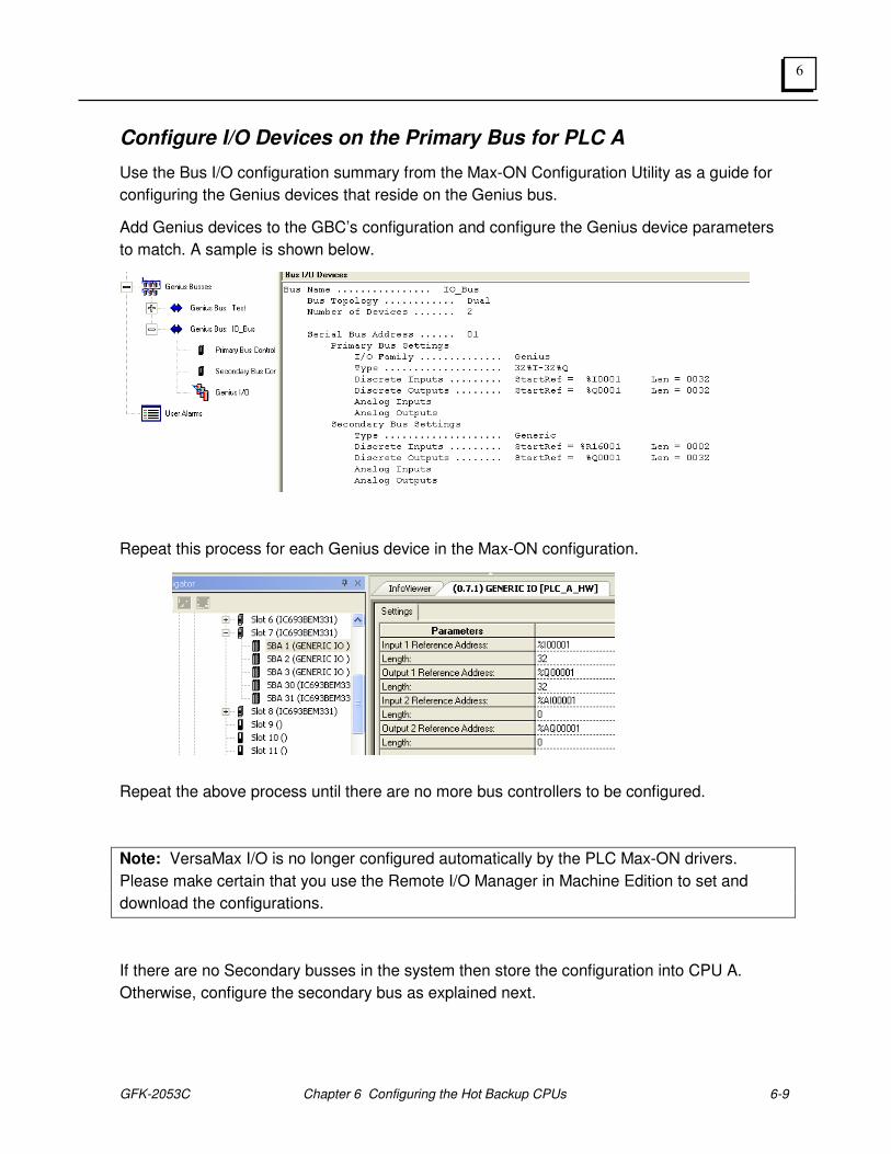
GFK-2053C Chapter 6 Configuring the Hot Backup CPUs 6-9
6
Configure I/O Devices on the Primary Bus for PLC A
Use the Bus I/O configuration summary from the Max-ON Configuration Utility as a guide for
configuring the Genius devices that reside on the Genius bus.
Add Genius devices to the GBC’s configuration and configure the Genius device parameters
to match. A sample is shown below.
Repeat this process for each Genius device in the Max-ON configuration.
Repeat the above process until there are no more bus controllers to be configured.
Note: VersaMax I/O is no longer configured automatically by the PLC Max-ON drivers.
Please make certain that you use the Remote I/O Manager in Machine Edition to set and
download the configurations.
If there are no Secondary busses in the system then store the configuration into CPU A.
Otherwise, configure the secondary bus as explained next.
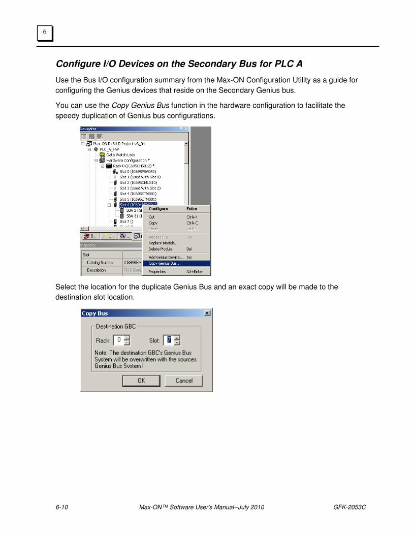
6-10 Max-ON™ Software User's Manual – July 2010 GFK-2053C
6
Configure I/O Devices on the Secondary Bus for PLC A
Use the Bus I/O configuration summary from the Max-ON Configuration Utility as a guide for
configuring the Genius devices that reside on the Secondary Genius bus.
You can use the Copy Genius Bus function in the hardware configuration to facilitate the
speedy duplication of Genius bus configurations.
Select the location for the duplicate Genius Bus and an exact copy will be made to the
destination slot location.
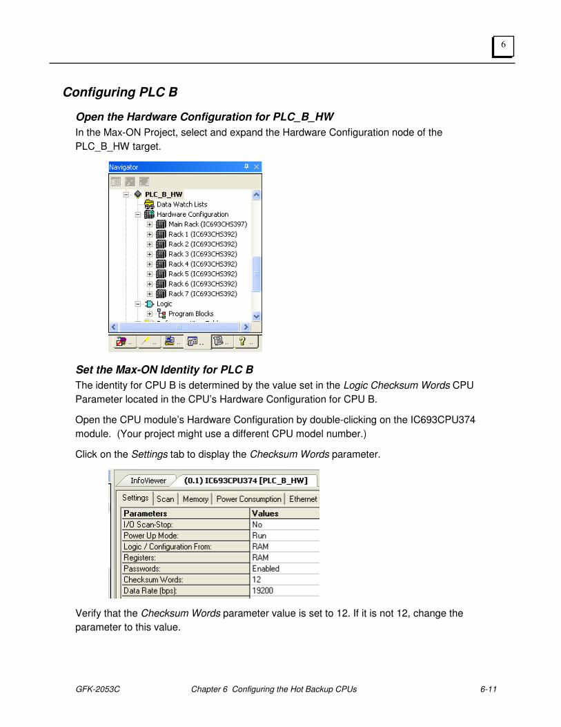
GFK-2053C Chapter 6 Configuring the Hot Backup CPUs 6-11
6
Configuring PLC B
Open the Hardware Configuration for PLC_B_HW
In the Max-ON Project, select and expand the Hardware Configuration node of the
PLC_B_HW target.
Set the Max-ON Identity for PLC B
The identity for CPU B is determined by the value set in the Logic Checksum Words CPU
Parameter located in the CPU’s Hardware Configuration for CPU B.
Open the CPU module’s Hardware Configuration by double-clicking on the IC693CPU374
module. (Your project might use a different CPU model number.)
Click on the Settings tab to display the Checksum Words parameter.
Verify that the Checksum Words parameter value is set to 12. If it is not 12, change the
parameter to this value.

6-12 Max-ON™ Software User's Manual – July 2010 GFK-2053C
6
Set Memory for PLC B
Normally, the memory in CPU B is configured the same as for CPU A. Please refer to the
information used for CPU A, and make adjustments to the CPU B memory configuration, if
necessary.
Configure Ethernet Sync Network for PLC B
Repeat the configuration process for the Ethernet synchronization interfaces in PLC B.
Configure Ethernet Interface for Ethernet I/O LANS for PLC B (if used)
Configure the Ethernet Interfaces used in conjunction with any Ethernet NIUs that are part of
your system.

GFK-2053C Chapter 6 Configuring the Hot Backup CPUs 6-13
6
Configure Genius Bus Controllers for PLC B (if used)
Serial Bus Address
All Genius bus controllers in PLC B should be configured to have their serial bus addresses
set at 30.
Input Default
Inputs should be set to Force OFF.
Status Reference Type
The recommended practice is set the device status address at the high end of the discrete
input status references. For instance, the first GBC might start at %I02017, length 32.
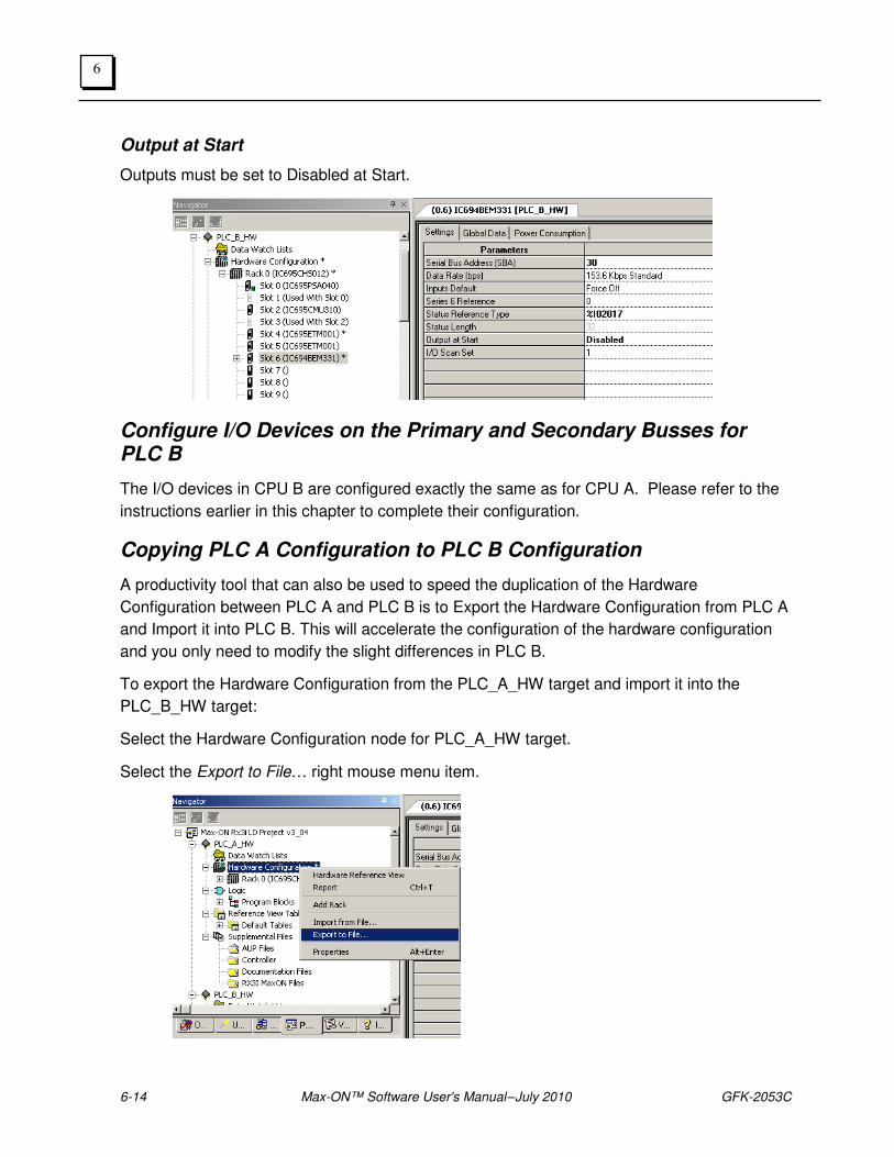
6-14 Max-ON™ Software User's Manual – July 2010 GFK-2053C
6
Output at Start
Outputs must be set to Disabled at Start.
Configure I/O Devices on the Primary and Secondary Busses for PLC B
The I/O devices in CPU B are configured exactly the same as for CPU A. Please refer to the
instructions earlier in this chapter to complete their configuration.
Copying PLC A Configuration to PLC B Configuration
A productivity tool that can also be used to speed the duplication of the Hardware
Configuration between PLC A and PLC B is to Export the Hardware Configuration from PLC A
and Import it into PLC B. This will accelerate the configuration of the hardware configuration
and you only need to modify the slight differences in PLC B.
To export the Hardware Configuration from the PLC_A_HW target and import it into the
PLC_B_HW target:
Select the Hardware Configuration node for PLC_A_HW target.
Select the Export to File… right mouse menu item.
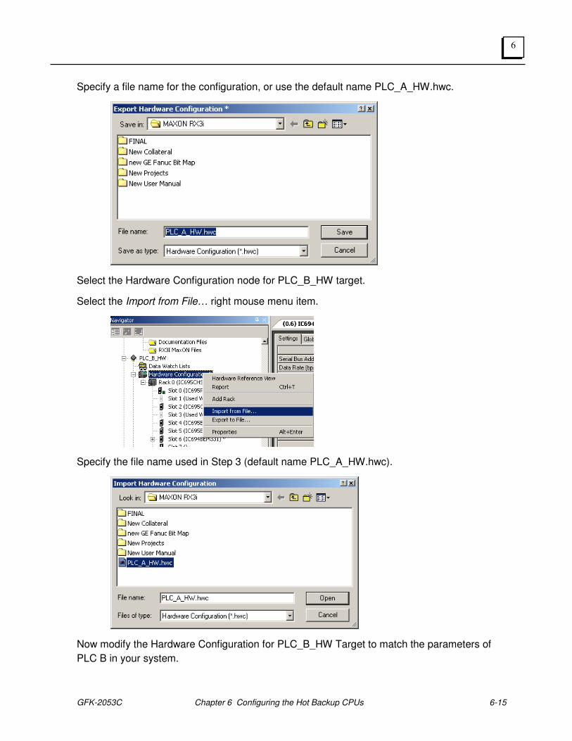
GFK-2053C Chapter 6 Configuring the Hot Backup CPUs 6-15
6
Specify a file name for the configuration, or use the default name PLC_A_HW.hwc.
Select the Hardware Configuration node for PLC_B_HW target.
Select the Import from File… right mouse menu item.
Specify the file name used in Step 3 (default name PLC_A_HW.hwc).
Now modify the Hardware Configuration for PLC_B_HW Target to match the parameters of
PLC B in your system.

6-16 Max-ON™ Software User's Manual – July 2010 GFK-2053C
6
GFK-2053C 7-1
Configuring the I/O Devices
Configuring the Genius I/O Devices
Before you may use your system, you must configure the Genius I/O devices that are to be
installed on the Genius I/O bus.
You must configure each device for:
• Serial Bus Address (SBA)
• Type of I/O (Input, Output, Combination)
• Scaling
• Defaults
Additionally, you must set the I/O to operate properly for redundancy:
• Dual I/O busses
• Hot Standby controller
Genius and Field Control I/O
While you are configuring the Genius I/O, you must configure extra parameters that govern
system operation with respect to redundant PLCs and redundant (dual) Genius I/O busses.
Please note that for Genius and Field Control I/O, you must have a Handheld Monitor
available to set these parameters.
Redundant Controllers
Using the Genius Handheld Monitor (HHM), set each Genus device for Redundant Controllers
= YES.
BSM Present
Using the Genius Handheld Monitor (HHM), set the BSM Present configuration parameter to
YES. This is required whether or not a dual Genius I/O bus is being used.
When this parameter is configured as YES, then the output default period is extended from 3
token rotation time periods to 2.5 seconds. The extra time allows the RX3i PLCs to exchange
mastership correctly.
Chapter
7

7-2 Max-ON Software User’s Manual– July 2010 GFK-2053C
7
BSM Controller
If the Genius I/O device is attached directly to a dual bus, either by a Bus Switching Module
(BSM) or a Bus Interface Unit (BIU), then you must configure this device to be a BSM
Controller.
Genius Block with BSM
In the case of a Genius Block connecting to the BSM, setting the block to be a BSM Controller
allocates its first output to the control of the BSM. It is assumed that the BSM is connected to
the first output circuit.
In the case of Field Control connecting to the BIU, setting the parameter to be a BSM
Controller directs the BIU to activate its internal bus switching circuitry.
If the device is connected to a “stub” downstream of another device that controls the
switching, then set BSM Controller to NO.
Genius VersaMax I/O
1. Add the VersaMax target(s) to your Machine Edition Project by selecting the Add
Target > GE IP Remote I/O > VersaMax Genius menu.
2. Click on the Target and rename it to match your application conventions.
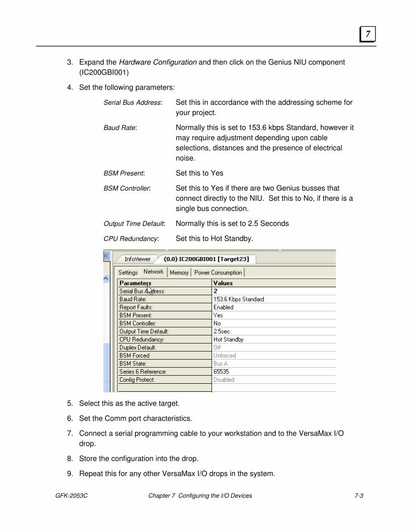
GFK-2053C Chapter 7 Configuring the I/O Devices 7-3
7
3. Expand the Hardware Configuration and then click on the Genius NIU component
(IC200GBI001)
4. Set the following parameters:
Serial Bus Address: Set this in accordance with the addressing scheme for
your project.
Baud Rate: Normally this is set to 153.6 kbps Standard, however it
may require adjustment depending upon cable
selections, distances and the presence of electrical
noise.
BSM Present: Set this to Yes
BSM Controller: Set this to Yes if there are two Genius busses that
connect directly to the NIU. Set this to No, if there is a
single bus connection.
Output Time Default: Normally this is set to 2.5 Seconds
CPU Redundancy: Set this to Hot Standby.
5. Select this as the active target.
6. Set the Comm port characteristics.
7. Connect a serial programming cable to your workstation and to the VersaMax I/O
drop.
8. Store the configuration into the drop.
9. Repeat this for any other VersaMax I/O drops in the system.
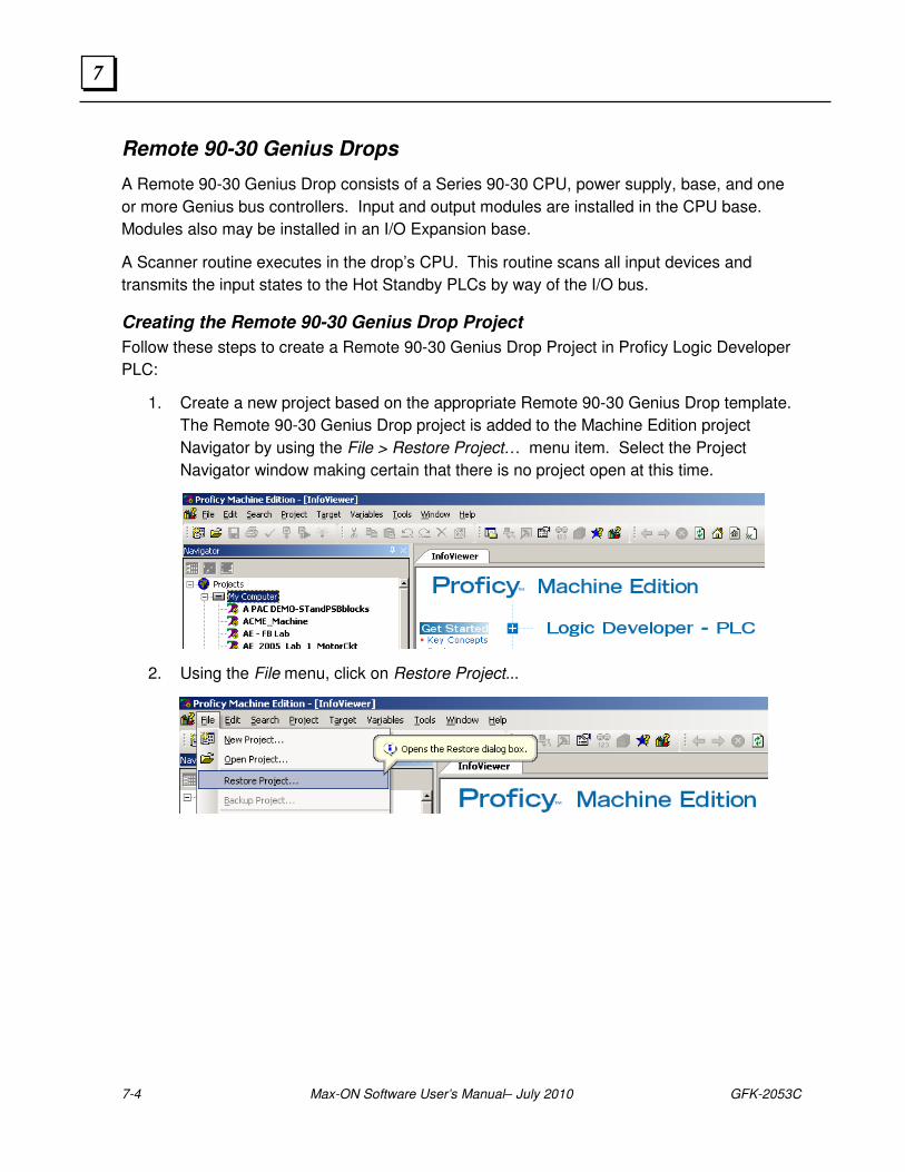
7-4 Max-ON Software User’s Manual– July 2010 GFK-2053C
7
Remote 90-30 Genius Drops
A Remote 90-30 Genius Drop consists of a Series 90-30 CPU, power supply, base, and one
or more Genius bus controllers. Input and output modules are installed in the CPU base.
Modules also may be installed in an I/O Expansion base.
A Scanner routine executes in the drop’s CPU. This routine scans all input devices and
transmits the input states to the Hot Standby PLCs by way of the I/O bus.
Creating the Remote 90-30 Genius Drop Project
Follow these steps to create a Remote 90-30 Genius Drop Project in Proficy Logic Developer
PLC:
1. Create a new project based on the appropriate Remote 90-30 Genius Drop template.
The Remote 90-30 Genius Drop project is added to the Machine Edition project
Navigator by using the File > Restore Project… menu item. Select the Project
Navigator window making certain that there is no project open at this time.
2. Using the File menu, click on Restore Project...

GFK-2053C Chapter 7 Configuring the I/O Devices 7-5
7
3. Navigate to the Proficy Components directory, then to the Remote Drops LD
directory. Open the desired Remote Drop directory, RemoteDrop CPU35x, 36x, 374
(small), for example. Make certain that the selection for Files of Type has been set to
Proficy Machine Edition (*.zip). Select the Remote Drop project backup file.
When you click on Open, a new project will be added to the Proficy Navigator window.
4. Give your project a descriptive name in the Machine Edition Navigator.

7-6 Max-ON Software User’s Manual– July 2010 GFK-2053C
7
Remote Drop Status Word
A remote drop always places important status information into its local references at %I00001
through %I00016 inclusive. The definition of these inputs is shown in the table below.
Bit Offset Description
1 Offline
2 Overrides Present
3 PLC Low Battery
4 Config Mismatch
5 Loss of I/O Module
6 Loss of Option Module
7 Option Module Hard Fault
8 Option Module Soft Fault
9 System Fault Present
10 I/O Fault Present
11 Program Changed
12 HW Config Changed
13 Power Up
14 Program Restart
15 Bus 1 LRC Error
16 Bus 2 LRC Error
To ensure proper operation of the remote drop, you must not configure any local module such
that it overlaps these discrete input addresses. Make certain that addressing for your
modules begins at %I00017 or above.
GFK-2053C Chapter 7 Configuring the I/O Devices 7-7
7
Configuring the Drop’s GBC
The Genius bus controller in the remote drop must be configured to transmit the input data to
the Hot Standby PLCs and also to receive global data from the Hot Standby PLCs. In the
Remote Drop, global data contains the discrete and analog output data.
Primary Bus
The Genius bus controller should be configured as follows:
In the Settings Tab
Serial Bus Address (SBA): Any address from 0 to 29 is acceptable. (Note: Normally a Genius Handheld Monitor normally is set for SBA=0. It is standard practice to avoid 0 when using Field Control or Genius I/O.)
Status Reference Type: %I00481 for M23, M31, and M40 drop folders %I02017 for M5S and M5L drop folders
In the Global Data Tab At the GBC’s Address:
Input 1 Address %I00001 Input 1 Length always 0 Input 2 Address %AI00001 Input 2 Length always 0 Output 1 Address %I00001 Output 1 Length 16 plus the number of Discrete Inputs installed Output 2 Address %AI00001 Output 2 Length The number of Analog Inputs installed
At SBA 30:
Input 1 Address See Buffer Registers Input 1 Length 62 Input 2 Address %AI00001 Input 2 Length always 0 Output 1 Address %Q00001 Output 1 Length always 0 Output 2 Address %AQ00001 Output 2 Length always 0
At SBA 31:
Input 1 Address See Buffer Registers Input 1 Length 62 Input 2 Address %AI00001 Input 2 Length always 0 Output 1 Address %Q00001 Output 1 Length always 0 Output 2 Address %AQ00001 Output 2 Length always 0
7-8 Max-ON Software User’s Manual– July 2010 GFK-2053C
7
Secondary Bus (optional)
The Genius bus controller should be configured as follows:
In the Settings Tab
Serial Bus Address (SBA): Any address from 0 to 29 is acceptable. (Note: Normally a Genius Handheld Monitor normally is set for SBA=0. It is standard practice to avoid 0 when using Field Control or Genius I/O.)
Status Reference Type: %I00449 for M23, M31, and M40 drop folders %I01985 for M5S and M5L drop folders
In the Global Data Tab At the GBC’s Address:
Input 1 Address %I00001 Input 1 Length always 0 Input 2 Address %AI00001 Input 2 Length always 0 Output 1 Address %I00001 Output 1 Length 16 plus the number of Discrete Inputs installed Output 2 Address %AI00001 Output 2 Length The number of Analog Inputs installed
At SBA 30:
Input 1 Address See Buffer Registers Input 1 Length 62 Input 2 Address %AI00001 Input 2 Length always 0 Output 1 Address %Q00001 Output 1 Length always 0 Output 2 Address %AQ00001 Output 2 Length always 0
At SBA 31:
Input 1 See Buffer Registers Input 1 Length 62 Input 2 %AI00001 Input 2 Length always 0 Output 1 %Q00001 Output 1 Length always 0 Output 2 %AQ00001 Output 2 Length always 0
The table shown below should be used to configure the Genius bus controller(s) in a remote
drop. The table lists the register references that must be entered into the Logic Developer
PLC hardware configuration based upon the template folder that was used to create the
remote drop.

GFK-2053C Chapter 7 Configuring the I/O Devices 7-9
7
Remote 90-30 Genius Drop Project Name
Description RemDrop
M23dxyy.zip RemDrop
M31dxyy.zip RemDrop
M4xdxyy.zip RemDrop
M5sdxyy.zip RemDrop
M5ldxyy.zip
Receive Buffer Primary Bus, CPU A
SBA-31
%R00705 %R01729 %R09680 %R09680 %R16065
Receive Buffer Secondary Bus, CPU A
SBA-31
%R00833 %R01857 %R09808 %R09808 %R16193
Receive Buffer Primary Bus, CPU B
SBA-30
%R00769 %R01793 %R09744 %R09744 %R16129
Receive Buffer Secondary Bus, CPU B
SBA-30
%R00897 %R01921 %R09872 %R09872 %R16257
Configuring the Discrete Output Range
Discrete output states are broadcast as global data from the Hot Standby PLCs. The global
data is intercepted by the Remote Drop and then mapped to local output states. The mapping
process allows output references from the Hot Standby PLCs to be translated to a different
set of output references in the remote drop.
For example, assume that your Remote Drop is implemented using a model IC693CPU323.
This CPU supports a maximum of 512 discrete output addresses. Your Hot Standby CPUs
are each a model IC695CMU310. This CPU supports 32640 output addresses. The mapping
process allows a portion of the output addresses in the range %Q00001..02048 to be mapped
into the range %Q00001..00512 at the remote drop.

7-10 Max-ON Software User’s Manual– July 2010 GFK-2053C
7
Configuring the Range
1. In Logic Developer PLC, open the Remote Drop project.
2. Using the navigator, open the Block named mxn_cfg.
3. Edit the first rung of data moves.
4. In the first MOVE function, a constant is moved into the reference named M_Q_ST
(Master CPU Starting Q Ref) Enter the starting reference for the outputs that are to be
received from the Hot Standby PLCs.
5. In the second MOVE function, a constant is moved into the reference named L_Q_ST
(Local Rack Starting Q Ref) Enter the starting reference for the outputs in the Remote
Drop in that you wish to place the Hot Standby values.
6. In the third MOVE function, a constant is moved into the reference named L_Q_LN
(Local Rack Q Length (bits)) Enter the number of outputs that are to be mapped into
the Remote Drop.
7. Save the Project.
8. Store the Project to the Remote Drop.
MOVEINT
MOVEINT
MOVEINT
1
1
IN Q M_Q_ST
%R09288
Master CPU Startng Q Ref
1
1
IN Q L_Q_ST
%R09289
Local Rack Startng Q Ref
256
1
IN Q L_Q_LN
%R09290
Local Rack Q Length (bits)

GFK-2053C Chapter 7 Configuring the I/O Devices 7-11
7
Configuring the Analog Output Range
Analog output values from the Hot Standby PLCs are intercepted by the Remote Drop and
then mapped (i.e. the output reference may be modified) to local output references.
For example, assume that your Remote Drop is implemented using a model IC693CPU323.
This CPU supports a maximum of 512 analog output addresses. Your Hot Standby CPUs are
each a model IC695CMU310. This CPU supports up to 32640 analog output addresses. The
mapping process allows a portion of the output addresses in the range %AQ00001..32640 to
be mapped into the range %AQ00001..00032 at the remote drop.
Configuring the Range
1. In Logic Developer PLC, open the Remote Drop project.
2. Using the navigator, open the Block named mxn_cfg.
3. Edit the second rung of data moves.
4. In the first MOVE function, a constant is moved into the reference named M_AQ_ST
(Master CPU Starting AQ Ref) Enter the starting reference for the outputs that are to
be received from the Hot Standby PLCs.
5. In the second MOVE function, a constant is moved into the reference named
L_AQ_ST (Local Rack Starting Q Ref) Enter the starting reference for the outputs in
the Remote Drop in that you wish to place the Hot Standby values.
6. In the third MOVE function, a constant is moved into the reference named L_AQ_LN
(Local Rack Q Length (words)) Enter the number of outputs that are to be mapped into
the Remote Drop.
7. Save the Project.
8. Store the Project to the Remote Drop.
MOVE
INTMOVE
INTMOVE
INT
1
1
IN Q M_AQ_ST
%R09291
Master CPU Startng AQ Ref
1
1
IN Q L_AQ_ST
%R09292
Local Rack Startng AQ Ref
25
1
IN Q L_AQ_LN
%R09293
Local Rack AQ Length (words)
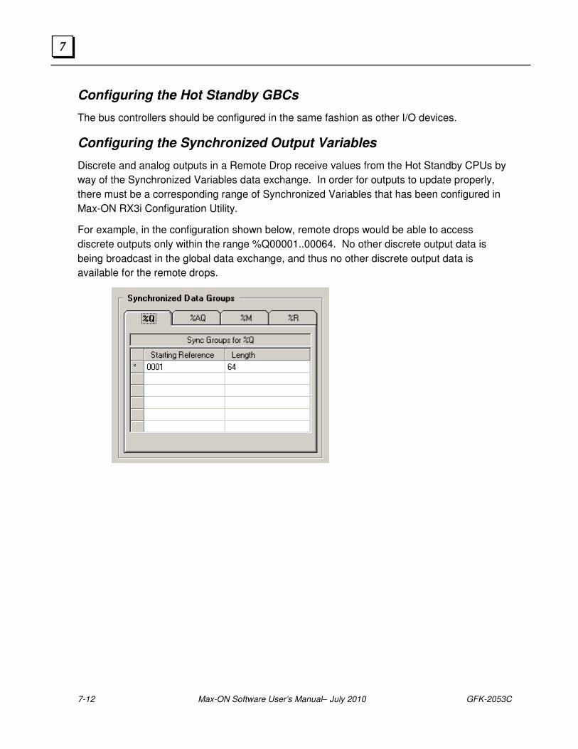
7-12 Max-ON Software User’s Manual– July 2010 GFK-2053C
7
Configuring the Hot Standby GBCs
The bus controllers should be configured in the same fashion as other I/O devices.
Configuring the Synchronized Output Variables
Discrete and analog outputs in a Remote Drop receive values from the Hot Standby CPUs by
way of the Synchronized Variables data exchange. In order for outputs to update properly,
there must be a corresponding range of Synchronized Variables that has been configured in
Max-ON RX3i Configuration Utility.
For example, in the configuration shown below, remote drops would be able to access
discrete outputs only within the range %Q00001..00064. No other discrete output data is
being broadcast in the global data exchange, and thus no other discrete output data is
available for the remote drops.

GFK-2053C Chapter 7 Configuring the I/O Devices 7-13
7

7-14 Max-ON Software User’s Manual– July 2010 GFK-2053C
7
GFK-2053C 8-1
Product Authorization
Without a valid product authorization, a Max-ON system will operate in demonstration mode for
22 days. While operating in this mode, all of the system’s capabilities are fully functional. At the
end of the demo period, PLC A will initiate an orderly transfer of Mastership to PLC B. Then
PLC A will shutdown automatically.
A Max-ON system that is installed in a production environment MUST be authorized in order to
allow PLC A to run indefinitely.
Generating the Key Code
In order for the authorization codes to be generated properly, the hardware configurations must
have been stored into CPUs A and B. Then the application target must have been stored as
well. When CPU A runs for the first time, it will generate a unique Key Code that it used to start
the authorization process.
Create the Authorization Request Form
1. Using Max-ON Tools Configuration package, make certain that the appropriate project file
has been opened.
8 Chapter
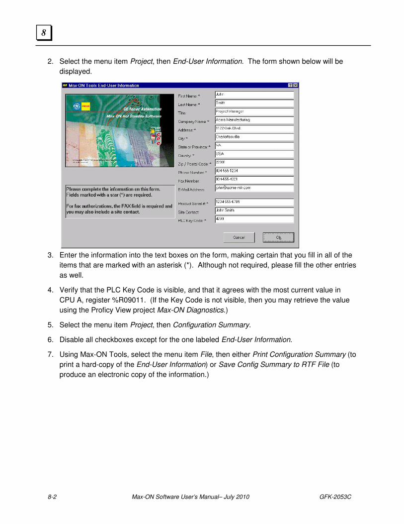
8-2 Max-ON Software User’s Manual– July 2010 GFK-2053C
8
2. Select the menu item Project, then End-User Information. The form shown below will be
displayed.
3. Enter the information into the text boxes on the form, making certain that you fill in all of the
items that are marked with an asterisk (*). Although not required, please fill the other entries
as well.
4. Verify that the PLC Key Code is visible, and that it agrees with the most current value in
CPU A, register %R09011. (If the Key Code is not visible, then you may retrieve the value
using the Proficy View project Max-ON Diagnostics.)
5. Select the menu item Project, then Configuration Summary.
6. Disable all checkboxes except for the one labeled End-User Information.
7. Using Max-ON Tools, select the menu item File, then either Print Configuration Summary (to
print a hard-copy of the End-User Information) or Save Config Summary to RTF File (to
produce an electronic copy of the information.)
GFK-2053C Chapter 8 Product Authorization 8-3
8
Obtain the Authorization Codes
Obtain your Authorization Codes from GE IP. The GE IP Authorization Desk is located in
Edmonton, Alberta (Canada). You may contact them by telephone, fax or e-mail:
Authorization Telephone Number 800-433-2682 (US and Canada)
780-420-2010 (if toll free 800 option is unavailable) available M-F; 8:00am-7:00pm, EST
Authorization Fax Number 780-420-2049
Authorization Email [email protected]
Enter the Authorization Codes
1. Using Max-ON Tools, select the menu item Configure, then Authorization Codes.
2. Enter the values that you received from GE IP into the corresponding text boxes.
3. When you finished entering all of the values, click Ok to continue.
4. Using Max-ON Tools, select the menu item File, then Save Project Folder. Max-ON Tools
will verify the authorization codes. If the authorization codes are valid, then you
5. A new configuration report will appear.
6. If the report contains the response, “The authorization codes are invalid”, then there has
been an error entering one or more of the codes. Correct your entry (entries) and then
repeat steps 3..5.
7. If the report contains the response, “The project is valid”, then the utility has revised your
project folder to include the new authorization codes.
8. Save the project configuration. This will update the project file and also revise the c-block
that is used by the PLC.
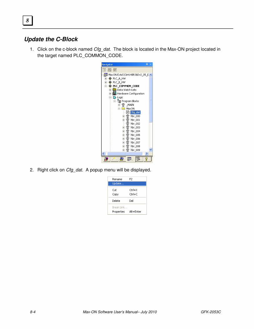
8-4 Max-ON Software User’s Manual– July 2010 GFK-2053C
8
Update the C-Block
1. Click on the c-block named Cfg_dat. The block is located in the Max-ON project located in
the target named PLC_COMMON_CODE.
2. Right click on Cfg_dat. A popup menu will be displayed.
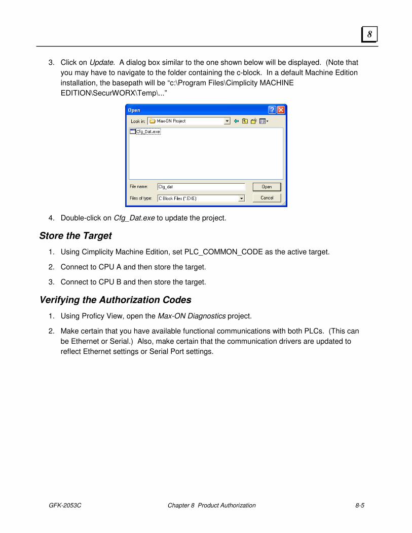
GFK-2053C Chapter 8 Product Authorization 8-5
8
3. Click on Update. A dialog box similar to the one shown below will be displayed. (Note that
you may have to navigate to the folder containing the c-block. In a default Machine Edition
installation, the basepath will be “c:\Program Files\Cimplicity MACHINE
EDITION\SecurWORX\Temp\...”
4. Double-click on Cfg_Dat.exe to update the project.
Store the Target
1. Using Cimplicity Machine Edition, set PLC_COMMON_CODE as the active target.
2. Connect to CPU A and then store the target.
3. Connect to CPU B and then store the target.
Verifying the Authorization Codes
1. Using Proficy View, open the Max-ON Diagnostics project.
2. Make certain that you have available functional communications with both PLCs. (This can
be Ethernet or Serial.) Also, make certain that the communication drivers are updated to
reflect Ethernet settings or Serial Port settings.
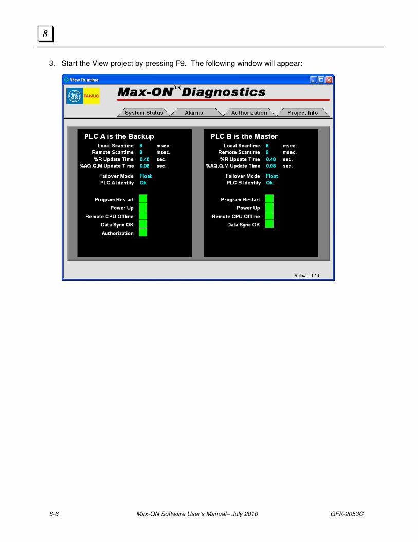
8-6 Max-ON Software User’s Manual– July 2010 GFK-2053C
8
3. Start the View project by pressing F9. The following window will appear:
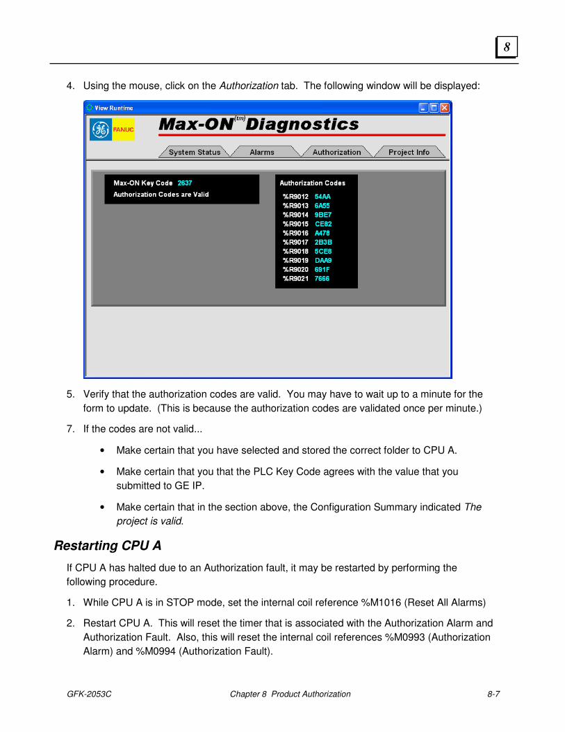
GFK-2053C Chapter 8 Product Authorization 8-7
8
4. Using the mouse, click on the Authorization tab. The following window will be displayed:
5. Verify that the authorization codes are valid. You may have to wait up to a minute for the
form to update. (This is because the authorization codes are validated once per minute.)
7. If the codes are not valid...
• Make certain that you have selected and stored the correct folder to CPU A.
• Make certain that you that the PLC Key Code agrees with the value that you
submitted to GE IP.
• Make certain that in the section above, the Configuration Summary indicated The
project is valid.
Restarting CPU A
If CPU A has halted due to an Authorization fault, it may be restarted by performing the
following procedure.
1. While CPU A is in STOP mode, set the internal coil reference %M1016 (Reset All Alarms)
2. Restart CPU A. This will reset the timer that is associated with the Authorization Alarm and
Authorization Fault. Also, this will reset the internal coil references %M0993 (Authorization
Alarm) and %M0994 (Authorization Fault).

8-8 Max-ON Software User’s Manual– July 2010 GFK-2053C
8
3. Wait approximately one or two minutes and then check to make certain that the
Authorization Fault (%M0993) remains cleared.

GFK-2053C Chapter 8 Product Authorization 8-9
8

8-10 Max-ON Software User’s Manual– July 2010 GFK-2053C
8
GFK-2053C 9-1
Updating an Existing Application
This chapter explains how to upgrade the Max-ON program blocks in your application to a
newer version of Max-ON using the Proficy Toolchest.
Overview
The general sequence for updating an application is as follows:
1. Revise the Hardware Configurations
• Update the existing hardware configuration for the target named PLC_A_HW.
• Update the existing hardware configuration for the target named PLC_B_HW.
2. Revise the Application with new Max-ON Drivers
• Backup your current project.
• Delete the Max-ON driver blocks (except for Cfg_Dat) from the target named
PLC_COMMON_CODE.
• Ctrl-Drag new Max-ON drivers from the Toolchest into the target named
PLC_COMMON_CODE.
3. Download both Hardware Configurations
• Select the hardware target that is associated with the Backup PLC. Set it as the Active
Target.
• Go online and place the Backup PLC into STOP mode.
• Download (Hardware only) the appropriate hardware target to the Backup PLC.
• Place the Backup PLC in RUN Mode.
• Go offline.
• Switch Mastership so that the current Backup becomes the Master.
• Select the hardware target that is associated with the new Backup PLC. Set it as the
Active Target.
• Go online and place the Backup PLC into STOP mode.
Chapter
9

9-2 Max-ON Software for the 90-30 Platform User's Manual – July 2010 GFK-2053C
9
• Download (H9ardware only) the appropriate hardware target to the Backup PLC while it
is in STOP mode.
• Place the Backup PLC in RUN Mode.
• Go offline.
4. Download the Application Logic
• Set PLC_COMMON_CODE as the Active Target.
• Adjust the target’s Ethernet I.P. address to match the address of the Backup PLC. (Or if
using a serial connection, connect to the programming port on the Backup PLC.)
• Download (Logic only) the target named PLC_COMMON_CODE into the Backup PLC.
• Place the Backup PLC in RUN Mode.
• Go offline.
• Switch Mastership so that the current Backup becomes the Master.
• Adjust the target’s Ethernet I.P. address to match the address of the Backup PLC. (Or if
using a serial connection, connect to the programming port on the Backup PLC.)
• Download (Logic only) the target named PLC_COMMON_CODE into the Backup PLC.
• Place the Backup PLC in RUN Mode.
Additional information on how to revise the three Max-ON targets follows.
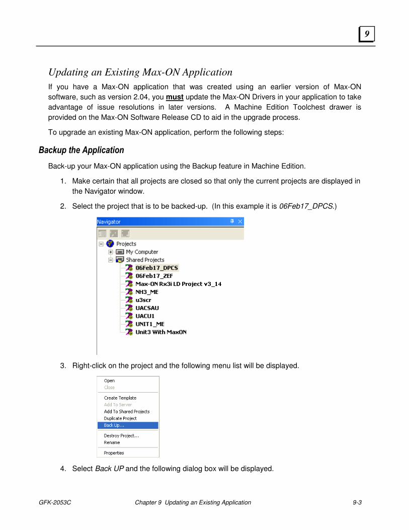
GFK-2053C Chapter 9 Updating an Existing Application 9-3
9
Updating an Existing Max-ON Application
If you have a Max-ON application that was created using an earlier version of Max-ON
software, such as version 2.04, you must update the Max-ON Drivers in your application to take
advantage of issue resolutions in later versions. A Machine Edition Toolchest drawer is
provided on the Max-ON Software Release CD to aid in the upgrade process.
To upgrade an existing Max-ON application, perform the following steps:
Backup the Application
Back-up your Max-ON application using the Backup feature in Machine Edition.
1. Make certain that all projects are closed so that only the current projects are displayed in
the Navigator window.
2. Select the project that is to be backed-up. (In this example it is 06Feb17_DPCS.)
3. Right-click on the project and the following menu list will be displayed.
4. Select Back UP and the following dialog box will be displayed.
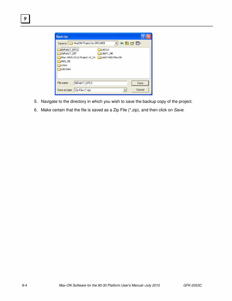
9-4 Max-ON Software for the 90-30 Platform User's Manual – July 2010 GFK-2053C
9
5. Navigate to the directory in which you wish to save the backup copy of the project.
6. Make certain that the file is saved as a Zip File (*.zip), and then click on Save.
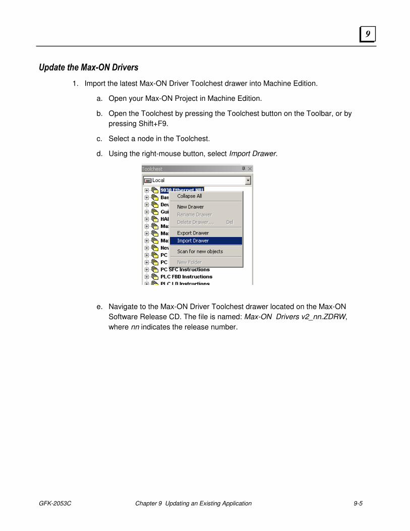
GFK-2053C Chapter 9 Updating an Existing Application 9-5
9
Update the Max-ON Drivers
1. Import the latest Max-ON Driver Toolchest drawer into Machine Edition.
a. Open your Max-ON Project in Machine Edition.
b. Open the Toolchest by pressing the Toolchest button on the Toolbar, or by
pressing Shift+F9.
c. Select a node in the Toolchest.
d. Using the right-mouse button, select Import Drawer.
e. Navigate to the Max-ON Driver Toolchest drawer located on the Max-ON
Software Release CD. The file is named: Max-ON Drivers v2_nn.ZDRW,
where nn indicates the release number.
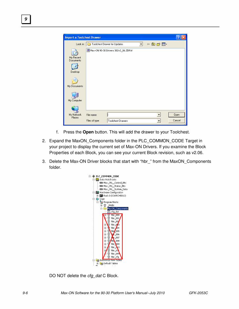
9-6 Max-ON Software for the 90-30 Platform User's Manual – July 2010 GFK-2053C
9
f. Press the Open button. This will add the drawer to your Toolchest.
2. Expand the MaxON_Components folder in the PLC_COMMON_CODE Target in
your project to display the current set of Max-ON Drivers. If you examine the Block
Properties of each Block, you can see your current Block revision, such as v2.06.
3. Delete the Max-ON Driver blocks that start with “hbr_” from the MaxON_Components
folder.
DO NOT delete the cfg_dat C Block.
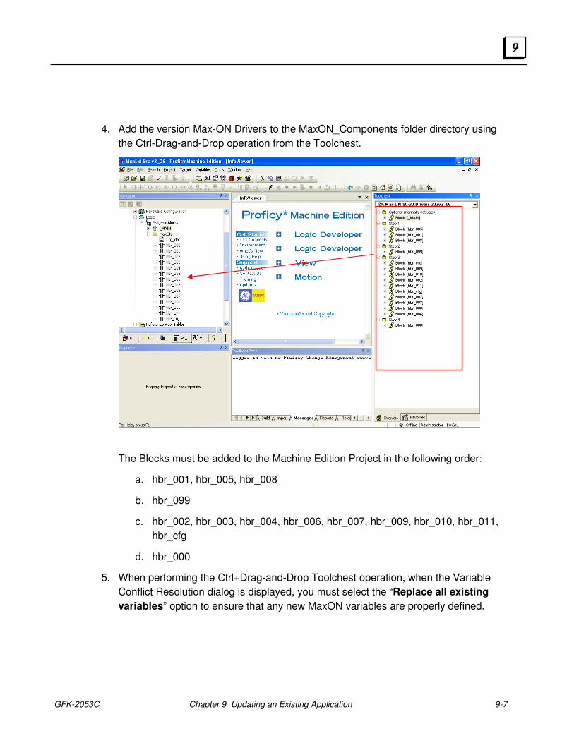
GFK-2053C Chapter 9 Updating an Existing Application 9-7
9
4. Add the version Max-ON Drivers to the MaxON_Components folder directory using
the Ctrl-Drag-and-Drop operation from the Toolchest.
The Blocks must be added to the Machine Edition Project in the following order:
a. hbr_001, hbr_005, hbr_008
b. hbr_099
c. hbr_002, hbr_003, hbr_004, hbr_006, hbr_007, hbr_009, hbr_010, hbr_011,
hbr_cfg
d. hbr_000
5. When performing the Ctrl+Drag-and-Drop Toolchest operation, when the Variable
Conflict Resolution dialog is displayed, you must select the “Replace all existing
variables” option to ensure that any new MaxON variables are properly defined.
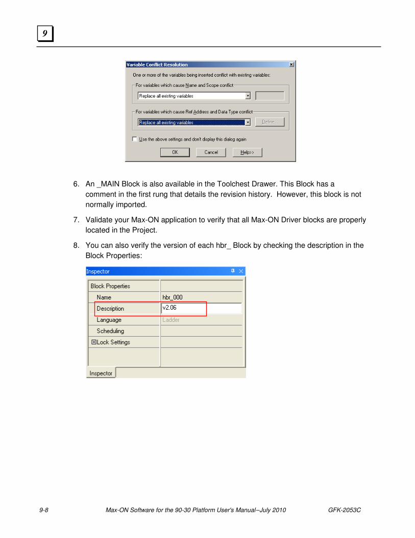
9-8 Max-ON Software for the 90-30 Platform User's Manual – July 2010 GFK-2053C
9
6. An _MAIN Block is also available in the Toolchest Drawer. This Block has a
comment in the first rung that details the revision history. However, this block is not
normally imported.
7. Validate your Max-ON application to verify that all Max-ON Driver blocks are properly
located in the Project.
8. You can also verify the version of each hbr_ Block by checking the description in the
Block Properties:

GFK-2053C Chapter 9 Updating an Existing Application 9-9
9

9-10 Max-ON Software for the 90-30 Platform User's Manual – July 2010 GFK-2053C
9
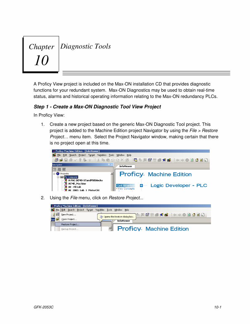
GFK-2053C 10-1
Diagnostic Tools
A Proficy View project is included on the Max-ON installation CD that provides diagnostic
functions for your redundant system. Max-ON Diagnostics may be used to obtain real-time
status, alarms and historical operating information relating to the Max-ON redundancy PLCs.
Step 1 - Create a Max-ON Diagnostic Tool View Project
In Proficy View:
1. Create a new project based on the generic Max-ON Diagnostic Tool project. This
project is added to the Machine Edition project Navigator by using the File > Restore
Project… menu item. Select the Project Navigator window, making certain that there
is no project open at this time.
2. Using the File menu, click on Restore Project...
Chapter
10
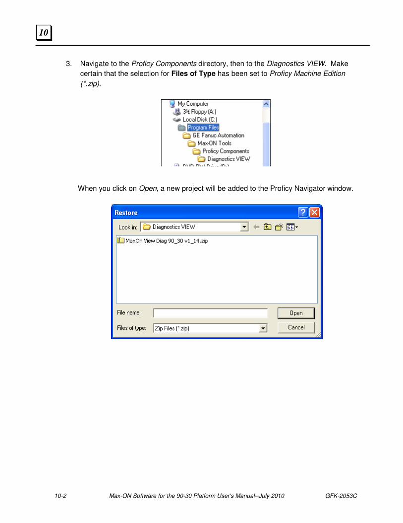
10-2 Max-ON Software for the 90-30 Platform User's Manual – July 2010 GFK-2053C
10
3. Navigate to the Proficy Components directory, then to the Diagnostics VIEW. Make
certain that the selection for Files of Type has been set to Proficy Machine Edition
(*.zip).
When you click on Open, a new project will be added to the Proficy Navigator window.
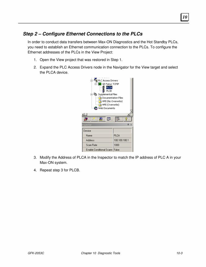
GFK-2053C Chapter 10 Diagnostic Tools 10-3
10
Step 2 – Configure Ethernet Connections to the PLCs
In order to conduct data transfers between Max-ON Diagnostics and the Hot Standby PLCs,
you need to establish an Ethernet communication connection to the PLCs. To configure the
Ethernet addresses of the PLCs in the View Project:
1. Open the View project that was restored in Step 1.
2. Expand the PLC Access Drivers node in the Navigator for the View target and select
the PLCA device.
3. Modify the Address of PLCA in the Inspector to match the IP address of PLC A in your
Max-ON system.
4. Repeat step 3 for PLCB.
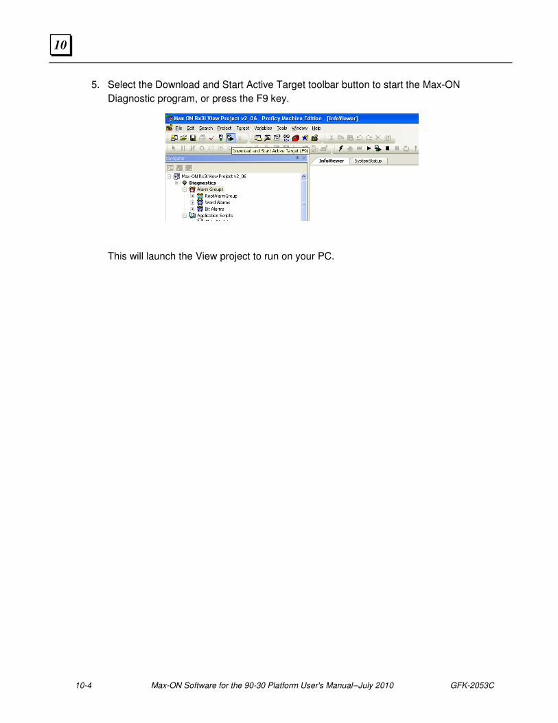
10-4 Max-ON Software for the 90-30 Platform User's Manual – July 2010 GFK-2053C
10
5. Select the Download and Start Active Target toolbar button to start the Max-ON
Diagnostic program, or press the F9 key.
This will launch the View project to run on your PC.
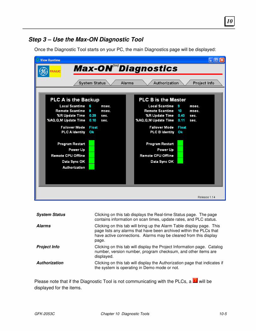
GFK-2053C Chapter 10 Diagnostic Tools 10-5
10
Step 3 – Use the Max-ON Diagnostic Tool
Once the Diagnostic Tool starts on your PC, the main Diagnostics page will be displayed:
System Status Clicking on this tab displays the Real-time Status page. The page contains information on scan times, update rates, and PLC status.
Alarms Clicking on this tab will bring up the Alarm Table display page. This page lists any alarms that have been archived within the PLCs that have active connections. Alarms may be cleared from this display page.
Project Info Clicking on this tab will display the Project Information page. Catalog number, version number, program checksum, and other items are displayed.
Authorization Clicking on this tab will display the Authorization page that indicates if the system is operating in Demo mode or not.
Please note that if the Diagnostic Tool is not communicating with the PLCs, a will be
displayed for the items.

10-6 Max-ON Software for the 90-30 Platform User's Manual – July 2010 GFK-2053C
10
The symbol indicates a Latched Alarm condition, where a symbol indicates a current
Alarm condition.
GFK-2053C Chapter 10 Diagnostic Tools 10-7
10
System Status
You may view items that relate to the current operating characteristics of your system on the
System Status page. An example is shown in the picture above.
PLC A and PLC B Status Indicates the operating status of the corresponding PLC, either Running or Stopped.
Local Scan Time The scan time, in milliseconds, for the Local PLC.
Remote Scan Time The scan time, in milliseconds, for the Remote PLC.
%R Update Time This is the time required to update synchronized data of type %R. The time is reported in seconds.
%AQ, Q, M Update Time This is the time required to update all configured synchronized data of the types %AQ, %M, and %Q. The time is reported in seconds.
Failover Mode This field indicates the mastership status of the corresponding PLC, either Master or Backup. There never should be two Masters or two Backups in a system that is operating properly.
PLC A and PLC B Identity A-Preferred, B-Preferred, or Float
Program Restart The local CPU has been switched from STOP mode to RUN mode.
Power Up The local CPU has undergone a power-up event.
Remote CPU Offline The companion PLC is offline. This may be due to the CPU being in STOP, Fault, or Powered Off. Also it may be due to a cable problem or Ethernet Interface failure.
Data Sync OK This field indicates the completion status for the transfer of synchronized data. The Backup CPU will indicate either Synced (all Synchronized Variables have been received) or Not Synced. The Master CPU always indicates Synced (ON). It is ON in the Backup CPU at the moment when all Synchronized Data items have been updated.
Authorization This indicates that PLC A is operating in DEMO mode. PLC A will operate for up to 22 days in this mode. At the end of the 22 day period, Mastership will transfer to PLC B (if it is available). At this point, PLC A will transition to STOP mode.
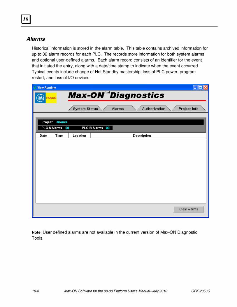
10-8 Max-ON Software for the 90-30 Platform User's Manual – July 2010 GFK-2053C
10
Alarms
Historical information is stored in the alarm table. This table contains archived information for
up to 32 alarm records for each PLC. The records store information for both system alarms
and optional user-defined alarms. Each alarm record consists of an identifier for the event
that initiated the entry, along with a date/time stamp to indicate when the event occurred.
Typical events include change of Hot Standby mastership, loss of PLC power, program
restart, and loss of I/O devices.
Note: User defined alarms are not available in the current version of Max-ON Diagnostic
Tools.
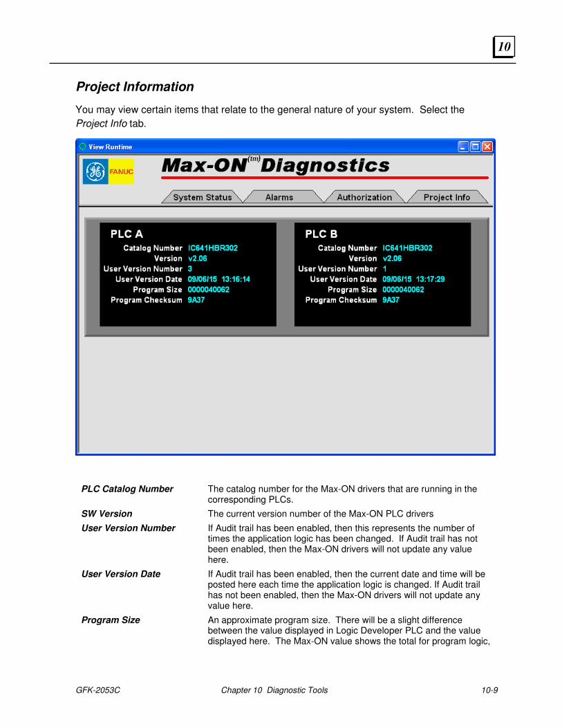
GFK-2053C Chapter 10 Diagnostic Tools 10-9
10
Project Information
You may view certain items that relate to the general nature of your system. Select the
Project Info tab.
PLC Catalog Number The catalog number for the Max-ON drivers that are running in the corresponding PLCs.
SW Version The current version number of the Max-ON PLC drivers
User Version Number If Audit trail has been enabled, then this represents the number of times the application logic has been changed. If Audit trail has not been enabled, then the Max-ON drivers will not update any value here.
User Version Date If Audit trail has been enabled, then the current date and time will be posted here each time the application logic is changed. If Audit trail has not been enabled, then the Max-ON drivers will not update any value here.
Program Size An approximate program size. There will be a slight difference between the value displayed in Logic Developer PLC and the value displayed here. The Max-ON value shows the total for program logic,

10-10 Max-ON Software for the 90-30 Platform User's Manual – July 2010 GFK-2053C
10
but does not include the memory overhead associated with subroutines.
Program Checksum The additive checksum for the Program. (This is a 16-bit entity, displayed as four hex digits.)
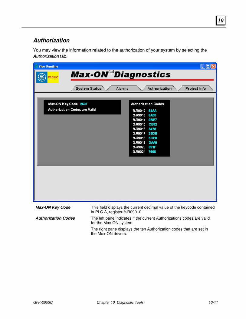
GFK-2053C Chapter 10 Diagnostic Tools 10-11
10
Authorization
You may view the information related to the authorization of your system by selecting the
Authorization tab.
Max-ON Key Code This field displays the current decimal value of the keycode contained in PLC A, register %R09010.
Authorization Codes The left pane indicates if the current Authorizations codes are valid for the Max-ON system.
The right pane displays the ten Authorization codes that are set in the Max-ON drivers.

10-12 Max-ON Software for the 90-30 Platform User's Manual – July 2010 GFK-2053C
10
GFK-2053C A-1
Ethernet Information
Ethernet Hardware
The Series 90-30 PLC offers two classes of modules that support Ethernet connectivity.
I/O Module
The IC693CMM321 module installs in the 90-30 rack to provide one network link. The module provides an AAUI connector that supports one link to a 10 megabit network by way of an external Ethernet transceiver.
CPU Modules
The IC693CPU364, IC693CPU370, IC693CPU372 and IC693CPU374 contain a built-in 10BaseT port. The CPU link has considerably higher throughput than the IC693CMM321 link.
PLC Sweep Mode
For the Ethernet interfaces to work efficiently, it is necessary to extend the scantime in one or both of the PLCs. The extra time is used to transfer Synchronized Variables through the CPU Communications Window. There are two approaches. Each has its own advantage.
Automatic Mode Selection –
In this approach, the system detects which CPU is the Backup and then sets the Backup to Constant Sweep. If there is a transfer in Mastership, then the Max-ON driver will set the Master CPU into Normal Sweep and the Backup to Constant Sweep.
Why you should consider this approach –
The Master always operates with the fastest scantime possible.
The Backup will adjust its timing regularly to meet current system requirements.
The period for Constant Sweep is determined automatically once per second. The value is calculated by adding 75 milliseconds to the Master’s scan time and then rounding downward to the nearest multiple of 5 milliseconds.
To enable this mode of operation:
1. Open your application folder.
A Appendix
A-2 Max-ON Software for the 90-30 Platform User's Manual – July 2010 GFK-2053C
A
2. Prior to the call to HBR_000, enter a rung that sets %M1012 to ON.
3. Store the application folder into CPU A.
4. Store the application folder into CPU B.
Manual Mode –
The second method is to configure the CPUs to execute in Constant Sweep mode. The configuration is entered via the Hardware Configuration utility. Both of the hardware configuration targets (PLC_A_HW and PLC_B_HW) must be set and then stored into the corresponding CPUs.
Why you should consider this approach –
By having the Master in Constant Sweep mode, Ethernet communications with HMIs may be improved dramatically.
Prerequisite: The system has been completed and is operating in its normal fashion (i.e., all application logic has been finished, HMIs are attached and communicating, and all peripherals are connected and operating normally.)
The procedure is as follows:
1. Record the peak PLC scantime in the Master CPU. You should observe the system for several minutes to obtain this value.
2. Add 75 to the value you obtained in step 1. Round this value up to the next multiple of 5.
3. Open the hardware configuration folder for CPU A.
4. Zoom into the CPU module. Click on the Scan tab.
5. Set the Sweep Mode to Constant Sweep.
6. Set the Sweep Timer to the value calculated in step 2.
7. Store the configuration into CPU A.
8. Open the hardware configuration folder for CPU B.
9. Repeat steps 4 through 6.
10. Store the configuration into CPU B.
11. Open your application folder.
12. Prior to the call to HBR_000, enter a rung that resets %M1012 to OFF.
13. Store the application folder into CPU A.
14. Store the application folder into CPU B.

GFK-2053C Appendix A Ethernet Information A-3
A

A-4 Max-ON Software for the 90-30 Platform User's Manual – July 2010 GFK-2053C
A
GFK-2053C B-1
Frequently Asked Questions
Does Max-ON Tools generate my hardware configuration?
No. You must use the Max-ON project report to produce the information that is used to guide you through the configuration.
Is the hardware configuration in the application folder used in any fashion?
Yes. The memory limits on the CPU must be set to be compatible with your application requirements. Note that you may have to adjust these in the two hardware configuration folders as well.
Can Max-ON Tools add on to one of my existing application folders.
No. You must start with the correct Max-ON project and then add your application to it.
Can I change the catalog number on my existing Max-ON project folder?
No. You will have to create a new project using the desired catalog number.
My two CPUs stop immediately after I store my Max-ON project. What did I do wrong?
One or more of the Synchronized Data types that you have configured is greater than the maximum quantity allowed for the product on which the project is based.
B Appendix
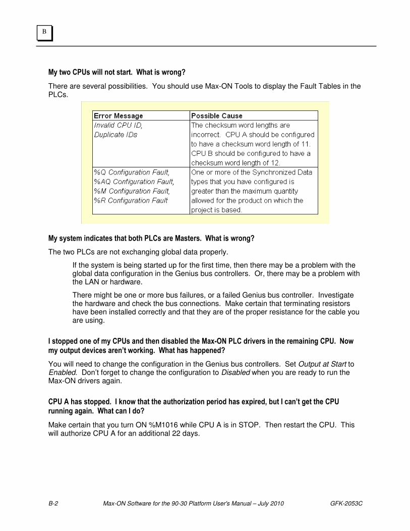
B-2 Max-ON Software for the 90-30 Platform User's Manual – July 2010 GFK-2053C
B
My two CPUs will not start. What is wrong?
There are several possibilities. You should use Max-ON Tools to display the Fault Tables in the PLCs.
My system indicates that both PLCs are Masters. What is wrong?
The two PLCs are not exchanging global data properly.
� If the system is being started up for the first time, then there may be a problem with the global data configuration in the Genius bus controllers. Or, there may be a problem with the LAN or hardware.
� There might be one or more bus failures, or a failed Genius bus controller. Investigate the hardware and check the bus connections. Make certain that terminating resistors have been installed correctly and that they are of the proper resistance for the cable you are using.
I stopped one of my CPUs and then disabled the Max-ON PLC drivers in the remaining CPU. Now my output devices aren’t working. What has happened?
You will need to change the configuration in the Genius bus controllers. Set Output at Start to Enabled. Don’t forget to change the configuration to Disabled when you are ready to run the Max-ON drivers again.
CPU A has stopped. I know that the authorization period has expired, but I can’t get the CPU running again. What can I do?
Make certain that you turn ON %M1016 while CPU A is in STOP. Then restart the CPU. This will authorize CPU A for an additional 22 days.

GFK-2053C Appendix B Frequently Asked Questions B-3
B

B-4 Max-ON Software for the 90-30 Platform User's Manual – July 2010 GFK-2053C
B
Index
GFK-2053C Index-1
Adding a Secondary Bus to an Existing Bus, 12
Adding an I/O Device, 14 Authorization, 11, 1
BSM Controller, 2 BSM Present, 1 Configuring Analog Inputs, 17, 19, 20, 22
Configuring Data Transfers, 25 Configuring the Analog Output Range, 11 Configuring the Drop's GBC, 7 Configuring the Ethernet Interface, 24 Configuring The Hot Standby GBCs, 12 Configuring the I/O Devices, 1 Configuring the Secondary Address, 23 Create the Authorization Request Form,
1 Creating a Connection to a PLC, 3 Creating a New Project, 2 Creating Connections to the PLCs, 3 Creating the Drop Folder, 4 Deleting a Module, 8 Deleting a Rack, 7
Deleting an I/O Device, 16 Diagnostics, 1 Editing an I/O Device, 16 Enter the Authorization Codes, 3 Ethernet Hardware, 1 Failover Time, 7 Fault Record Structure, 21 Fault Table, 21 Frequently Asked Questions, 1 Genius and Field Control I/O, 1 Genius and Field Control I/O (Config. I/O),
1 Genius Bus Controllers, 6, 7, 13
Genius Bus Controllers - CPU A, 7
Genius Bus Controllers - CPU B, 13 I/O Bus Topologies, 9 I/O devices, 9, 10, 14
adding, 14
deleting, 16
editing, 16
Identity - CPU A, 3 Identity - CPU B, 11 Indicating Mastership, 3 Key code, 1 Mastership Modes, 11 Memory, 4, 12 Obtain the Authorization Codes, 3 Online Project Information, 7, 9, 11 PID Function Blocks, 17 PLC Sweep Mode, 1
Product authorization, 1 Product Authorization, 11
Programming, 1 Project information, 7, 9, 11
Project workflow, 2 Redundant Controllers, 1 Remote 90-30 Drops, 4 Remote Drop Status Word, 6 Remote Status Flags, 8 Retrieve the PLC Key Code, 1 Secondary bus
adding, 12
Selecting a Master, 11 Setting a Preferred Master, 13 Simplex Genius Bus, 9 Synchronized Data Transfers, 7 System Command Flags, 10 System Data Registers, 16
System Level Alarms, 25
System Options, 32 System Status Flags, 2 Technical Support. See page v Time Stamp Record Structure, 21
Troubleshooting diagnostic tools, 1
frequently asked questions, 1
Uninstalling Max-ON Tools, 4 Verifying the Authorization Codes, 5 Welcome, 1 Working with Projects, 1