maxwell mission ha ndbook - colorado.edu
TRANSCRIPT

MAXWELL Mission Handbook Revision 1.1 2020-05-08
Aaron P. Aboaf
University of Colorado Boulder

Table 1. Approvals
Signature Asset Signature Asset
Prof. Scott Palo Principal
Investigator
Prof. Robert Marshall
Co-Principal Investigator
Prof. Marcin Pilinski Project Advisor
Dr. Nicholas Rainville
Project Advisor
Aaron Aboaf Project Manager
Matthew Zola Deputy Project
Manager
Elliott Harrod Chief Systems
Engineer
Adam Gardell Software Systems
Engineer
MAXWELL Mission Handbook 2
DocuSign Envelope ID: DA15CB0C-2990-4746-A937-2D0F5BBF023B

Table 2. Document Revisions
Release Date Description Primary Author
0.1 2019-10-30 Pre-release version. Document outline identified, seeking feedback from Advisors.
Aaron Aboaf
0.2 2019-12-18 End of Fall 2019 semester release. Feedback from this revision will be incorporated into the first official release of the document.
Aaron Aboaf
1.0 2020-04-30
Added Sponsorship, Distribution C Documents, Day In The Life, Mission Milestones, Spacecraft Standards, Waterfall Charts, Note on CDMA, X-band transmitter, Document Tracking & Official Releases, Recruitment, Team motivation & success, 443 Onboarding, EAR/ITAR & ESD Training, Team Organization, MAXWELL Documentation, Work breakdown, full Risk section, Technology Demonstration, Launch opportunities, figures in early sections, Spacecraft Requirements, Spacecraft bus (various authors), Thermal considerations. This release is the first official approved public release of this document.
Aaron Aboaf
1.1 2020-05-08
Links added to CDMA resources, Links added for SC coordinate frame definition, Figures & info updated for updated MMA T-DaHGR sizing, Systems Engineering Section with block diagram and budget tables (all of which automatically update from their source document, cool!), photo of LASP Yagi antenna.
Aaron Aboaf
MAXWELL Mission Handbook 3

This page intentionally left blank
MAXWELL Mission Handbook 4
Table of Contents Acronyms 8
Document Scope 9
Mission Overview 9
Mission Impact 12
Sponsorship 13
The University Nanosatellite Program 13
Regulations 13
University Regulations 13
Tax-Exempt Status 13
Non-Disclosure Agreements 14
Export Compliance 14
FCC & Other Agency Regulations 16
Mission Objectives 17
Note On CDMA 18
Lifecycle & Concept of Operations 19
Phase 1: Ejection, Detumble, First Contact 20
Phase 2: Commissioning 20
Phase 3: Communications Demonstrations 21
Phase 4: CSAC Experiment 21
Phase 5: T-DaHGR Demonstration 21
Phase 6: End of Life 22
A Day In The Life 22
Phase 2 & Phase 4 Day In The Life 22
Phase 3 & Phase 5 Day In The Life 23
Mission Milestones 23
Systems Engineering 24
Spacecraft System Overview 26
Spacecraft System Budgets 27
Link Budget 27
Mass Budget 28
Power Budget 29
Data Budget 29
Spacecraft Level Requirements 30
MAXWELL Mission Handbook 5

UNP User’s Guide 30
Communications Mission Requirements 31
Science Mission Requirements 31
Spacecraft Bus Requirements 31
Ground Support & Testing Requirements 33
Spacecraft Standards 33
Units of Measurement 34
Spacecraft Body Coordinate System 34
Other Reference Coordinate Systems 35
Spacecraft Bus System 35
Mechanical Design 35
Electrical Power System Design 37
Command & Data Handling System Design 37
Lithium Radio 39
Attitude Determination & Control System Design 39
Thermal Considerations 40
Spacecraft Payload Systems 41
Payload Computer Board 41
X-band Transmitter 41
S-band Receiver 42
Chip Scale Atomic Clock 42
Ground Systems 43
UHF Ground System 43
S-band Ground Station 45
X-Band Ground Station 45
Programmatics 46
Document Tracking and Official Releases 46
Project Infrastructure 48
Personnel 50
Recruitment 51
Team Motivation & Success 53
Buy In 54
Tasks & Schedule 54
Onboarding Process 55
STIg Lab Onboarding & Access 55
443 Lab Onboarding & Access 55
ESD & EAR/ITAR Training 56
MAXWELL Mission Handbook 6
MAXWELL Documentation 56
Google Shared Drive Organization 56
Project Templates 57
MAXWELL Document Style 57
Team Organization 58
Student Leadership Roles 59
Principal Investigator & Advisor Roles 60
Other Student Roles 61
Work Breakdown & Overlap 61
Risks 61
Programmatic vs. Technical Risks 62
Team Risk Approach 63
Risk Tracking 63
Risk Mitigation 64
Technology Demonstration Plan 65
Launch Opportunities 65
Requirements Verification 66
Mission Validation 67
MAXWELL Mission Handbook 7

Acronyms Table 3. Acronyms
MAXWELL | Multiple Access X-band Wave Experiment in Located in LEO
Acronym Expanded Form Acronym Expanded Form
RF Radio Frequency MO Mission Objective
CDMA Code Division Multiple Access CSAC Chip Scale Atomic Clock
GPS Global Positioning System TRL Technology Readiness Level
UHF Ultra High Frequency STEM Science Technology Engineering Math
ASEN Aerospace Engineering CAD Computer Aided Design
AFOSR Air Force Office of Scientific Research AFRL Air Force Research Laboratory
UNP University Nanosatellite Program NDA Non-Disclosure Agreement
ITAR International Traffic in Arms Regulations EAR Export Administration Regulations
FRE Fundamental Research Exclusion POC Point of Contact
FCC Federal Communications Commision LEO Low Earth Orbit
CONOPS Concept of Operations PI Principal Investigator
CDR Critical Design Review RVM Requirements Verification Matrix
LASP Laboratory for Atmospheric & Space Physics EGSE Electrical Ground Support Equip.
SI International System of Units ECEF Earth Centered Earth Fixed
ADCS Attitude Determination & Control CUE3 University of Colorado Earth Escape Explorer
EPS Electrical Power System CDH Command & Data Handling
GSE Ground Support Equipment ADC Analogue to Digital Converter
GPIO General Purpose Input/Output SoC State of Charge
TT&C Telemetry Tracking & Command BBB BeagleBone Black Industrial
EKF Extended Kalman Filter PLDC Payload Computer
MAXWELL Mission Handbook 8

FPGA Field Programmable Gate Array LNA Low Noise Amplifier
DoD US Department of Defense SDR Software Defined Radio
EIRP Isotropic Radiator Power CCSDS Packet Definition
CRC Cyclic Redundancy Check GCM Galois/Counter Mode
ICD Interface Control Document STIg Satellite Technology Integration
EE Electrical Engineering ESD Electro-Static Discharge
MS Microsoft Corporation PM Project Manager
DPM Deputy Project Manager SSE Software Systems Engineer
SE Systems Engineer CE Chief Engineer
EOSR End of Semester Review SERB Space Experiments Review Board
CSLI CubeSat Launch Initiative EDU Engineering Development Unit
MPPT Maximum Power Point Tracking HK Housekeeping Packet
PCA Potential Capability Area PCB Printed Circuit Board
Document Scope This is the MAXWELL (Multiple Access X-band Wave Experiment Located in LEO) Mission
Handbook. The goal of this document is to provide a comprehensive collection of high level programmatic and technical information about the MAXWELL CubeSat Mission. This document will provide an insight into the programmatic vision for the MAXWELL project, detail the system requirements and traceability, and also provide a technical introduction to how the system is designed and operated. It is in part a project Systems Engineering Manual, in part a Project Management Plan, and in part a detailed mission overview. After reading through this document one should have a fairly good understanding of what the MAXWELL mission is, why it is relevant, how the spacecraft works, how the ground system works, and how the system was built, how the system performed, and how the system meets the mission objectives set forth.
Mission Overview MAXWELL is a 6U CubeSat mission designed, built, and tested at the University of
Colorado Boulder. The mission is centered around the demonstration of advanced RF communications technology for X-band downlink and S-band uplink on a CubeSat platform. The six major mission objectives are detailed in table 7 and all seek to demonstrate different communications capabilities for use on future CubeSat missions. The Principal Investigator of
MAXWELL Mission Handbook 9

MAXWELL is professor Scott E. Palo and the Co-PI is professor Robert Marshall. Both are faculty members of the University of Colorado Boulder Smead Department of Aerospace Engineering Sciences. Table 29 contains the acceptable orbital parameters for the final mission.
The Mission Objectives are listed in table 7. Mission objectives 1, 3, and 6 are directly related to X-band communications technology. The MAXWELL CubeSat will accomplish MO-1 and MO-3 using the XTx which is an X-band transmitter radio developed by Professor Scott Palo in association with Blue Cubed. The XTx is capable of operating at 30Mbps from low earth orbit in narrow-band mode and at 2Mbps in a CDMA (Code Division Multiple Access) multiuser spread spectrum mode fulfilling the requirements to meet MO-1 and MO-3 respectively.
MAXWELL is also partnering with MMA Design LLC., a small antenna developer located in Broomfield, CO to accomplish MO-6. The T-DaHGR is a 1U deployable high-gain X-band reflectarray antenna that, once deployed, becomes a 1600cm 2 antenna. Flying the T-DaHGR is a capability addition to the advancement of the TRL of this X-band technology which can improve communication rates by being able to deliver a high gain antenna in a small 1U CubeSat sized deployable package.
Mission objectives 2 and 4 are both concentrating on S-band technology for spacecraft uplink communications. The S-band radio designed for this application is managed by Professor Scott Palo and PhD students in his research group. This receiver uses an Igloo2 FPGA for signal processing and the S-band RF board and signal demodulation electronics were put together by Master’s student Les Warshaw. The S-band RF receiver is tested thoroughly as part of the verification process prior to launching MAXWELL into orbit to make sure that MO-2 and 4 can be met.
Mission objective 5 is not part of the communications demonstrations but is an added value experiment to the MAXWELL mission. Mission objective 5 is part of an interdepartmental collaboration with Professor Penina Axelrad to characterize the performance of the Chip Scale
Atomic Clock (CSAC) against GPS clocks in orbit and evaluate the potential to use a CSAC for precision navigation and timing applications outside of GPS lock. This mission is funded through the University Nanosatellite Program which is an office of the Air Force Research Laboratory. The funding received covers the design, build, test, and verification of the spacecraft. The letter of funding commitment
MAXWELL Mission Handbook 10
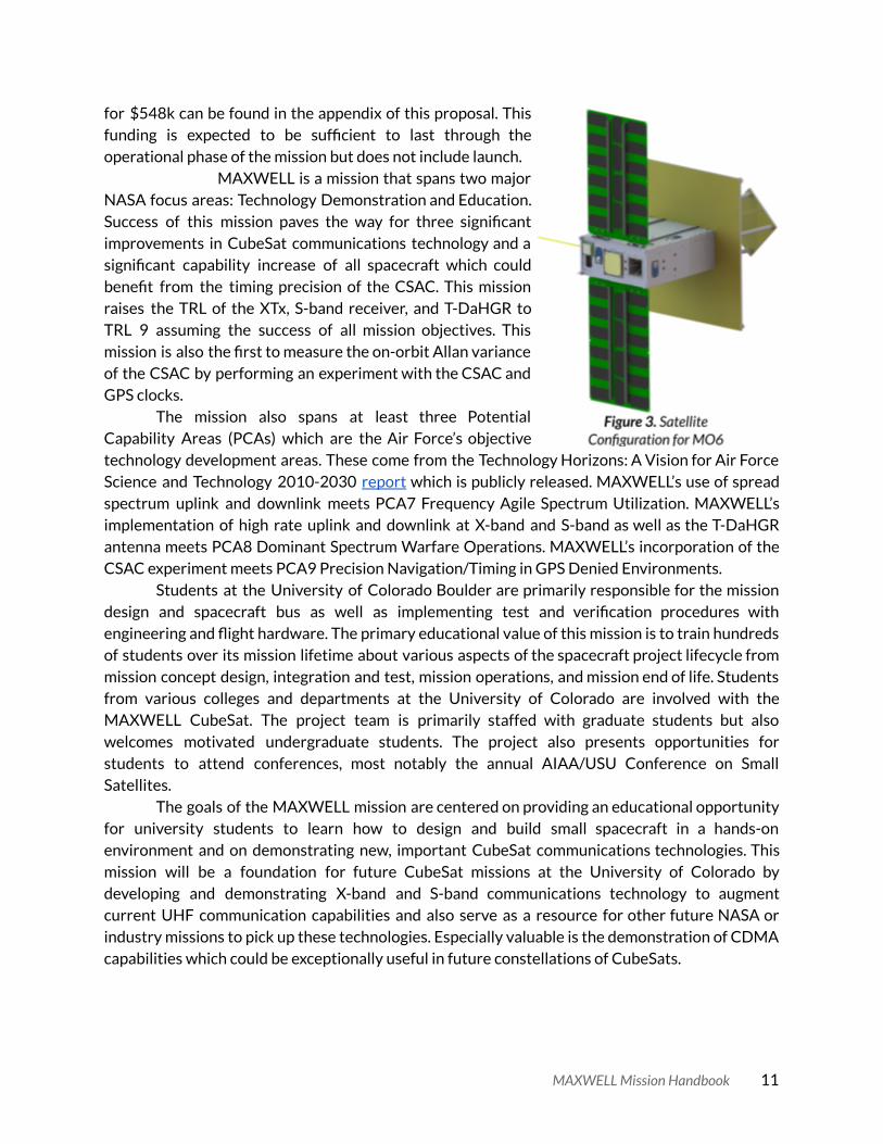
for $548k can be found in the appendix of this proposal. This funding is expected to be sufficient to last through the operational phase of the mission but does not include launch.
MAXWELL is a mission that spans two major NASA focus areas: Technology Demonstration and Education. Success of this mission paves the way for three significant improvements in CubeSat communications technology and a significant capability increase of all spacecraft which could benefit from the timing precision of the CSAC. This mission raises the TRL of the XTx, S-band receiver, and T-DaHGR to TRL 9 assuming the success of all mission objectives. This mission is also the first to measure the on-orbit Allan variance of the CSAC by performing an experiment with the CSAC and GPS clocks.
The mission also spans at least three Potential Capability Areas (PCAs) which are the Air Force’s objective technology development areas. These come from the Technology Horizons: A Vision for Air Force Science and Technology 2010-2030 report which is publicly released. MAXWELL’s use of spread spectrum uplink and downlink meets PCA7 Frequency Agile Spectrum Utilization. MAXWELL’s implementation of high rate uplink and downlink at X-band and S-band as well as the T-DaHGR antenna meets PCA8 Dominant Spectrum Warfare Operations. MAXWELL’s incorporation of the CSAC experiment meets PCA9 Precision Navigation/Timing in GPS Denied Environments.
Students at the University of Colorado Boulder are primarily responsible for the mission design and spacecraft bus as well as implementing test and verification procedures with engineering and flight hardware. The primary educational value of this mission is to train hundreds of students over its mission lifetime about various aspects of the spacecraft project lifecycle from mission concept design, integration and test, mission operations, and mission end of life. Students from various colleges and departments at the University of Colorado are involved with the MAXWELL CubeSat. The project team is primarily staffed with graduate students but also welcomes motivated undergraduate students. The project also presents opportunities for students to attend conferences, most notably the annual AIAA/USU Conference on Small Satellites.
The goals of the MAXWELL mission are centered on providing an educational opportunity for university students to learn how to design and build small spacecraft in a hands-on environment and on demonstrating new, important CubeSat communications technologies. This mission will be a foundation for future CubeSat missions at the University of Colorado by developing and demonstrating X-band and S-band communications technology to augment current UHF communication capabilities and also serve as a resource for other future NASA or industry missions to pick up these technologies. Especially valuable is the demonstration of CDMA capabilities which could be exceptionally useful in future constellations of CubeSats.
MAXWELL Mission Handbook 11

Mission Impact The MAXWELL mission has a broad impact facilitated by its technological development
goals and involvement as a graduate project at the University of Colorado Boulder. The MAXWELL mission also seeks to have community involvement in the education and encouragement of the pursuit of STEM careers among grade school students. The project has two primary goals. The first is to provide a means of education regarding the design, build, test, and operation of real satellite systems for students at the university level. The second is to produce a functional satellite system that will actually fly in space.
Regarding the first goal of educating students, the MAXWELL project has involved graduate and undergraduate students at the University of Colorado since its inception in the Spring of 2016. An estimated 75 students have been significantly involved in the development of the MAXWELL CubeSat to date with more on the horizon. Typically students tend to be from the graduate program and are involved formally through the ASEN 5018/6028 graduate projects course or through an Independent Study facilitated through the ASEN department. Some undergraduates have also been involved with the project. Typically undergraduate involvement is limited through a Discovery Learning Apprenticeship (DLA) program, but some undergraduate students have done exceptional work and become active volunteers or paid students working on the project.
The MAXWELL management team also sees the value of active outreach to promote the project and to promote STEM involvement in the community. One of the most important pillars of this philosophy is to maintain an active image in the engineering college and aerospace department. Having other students know about the project is essential to keeping enrollment numbers up in order to have the team staffed as best as possible each semester. There are also other opportunities for outreach and promotion at conferences. As the MAXWELL project matures, opportunities arise for public presentations about the project at conferences including the CubeSat Developers Workshop at CalPoly and the AIAA/USU Conference on Small Satellites at Utah State University in Logan, Utah. These are two opportunities that the MAXWELL project plans to present a mission overview at in 2020.
Completion of the mission’s communication experiments will also lead to opportunities to publish additional papers on the performance of the mission. These papers will likely have a collaborative aspect with industry as well since the X-band experiments onboard the satellite are sponsored in part by industry partners. Blue Cubed LLC is the developer of the XTx radio platform that is supporting MAXWELL s-band communication experiments. MMA Design LLC is the supplier of the proposed T-DaHGR Antenna which is to be flown and tested on the MAXWELL satellite. These two industry partners along with students and faculty at the University of Colorado have a vested interest in publishing the performance results of the communications experiments performed via the MAXWELL satellite platform.
Management also plans to support some high school outreach in the Spring of 2020 as part of a collaborative effort with high school students with developed skills in CAD modeling, 3D manufacturing, and programming.
MAXWELL Mission Handbook 12

Sponsorship
The University Nanosatellite Program The University Nanosatellite Program (UNP) is jointly administered by the Air force Office
of Scientific Research (AFOSR) and the Air Force Research Laboratory (AFRL). The program funds university students to design, build, launch, and operate small satellites. The UNP program is a competitive downselect process where universities compete for funding and launch opportunities based on technical reviews early in the project lifecycle. Since the program inception in 1999, 38 universities have participated and nearly 5,000 students have gained experience building and operating small satellites before transitioning into career positions at AFRL and other industry companies.
MAXWELL entered the UNP-9 program in 2016 and was selected from a group of 10 universities at the Flight Selection Review (FSR) in January 2018. This marked the end of Phase A of the program lifecycle. After the conclusion of Phase A, Phase B begins which is the assembly, integration, and test of the engineering and flight satellite systems. Following Phase B is the environmental testing and launch operations in Phase C and then mission operations designated as Phase D. MAXWELL is expected to launch in early 2021 and to conduct operations through the second quarter of 2022.
Regulations An important part of conducting the MAXWELL project is to understand the regulatory
environment the project is subject to. This regulatory environment is two fold; first under the University of Colorado, and second under United States Federal regulations. Both of these regulatory environments impact the processes and procedures used while conducting this project.
University Regulations
Tax-Exempt Status There are several University of Colorado regulations that this project is subject to. First,
and most importantly is the Tax-Exempt status of the University of Colorado. Any purchases for business use by the University of Colorado are by law tax exempt both at the federal, state, and local level. Any purchase of hardware or software for the purposes of moving the MAXWELL project forward are included in this designation and the project manager should have the required information and tools to make all purchases for the project.
MAXWELL Mission Handbook 13

Non-Disclosure Agreements There are some aspects of the MAXWELL project that are governed by Non-Disclosure
Agreements (NDAs). The purpose of these NDAs is to protect the proprietary information of our commercial partners that the MAXWELL team members have access to in order to perform their responsibilities on the team. Table 4 details the different NDAs that the MAXWELL team members are subject to. It should be noted that the NDAs cover every student at the University of Colorado so sharing proprietary information among students on the team is not an issue. Each student that is shared the information should be notified of the information that is under the NDA and that they cannot disclose that information to anyone not directly affiliated or enrolled at the University of Colorado.
Table 4. List of Non-Disclosure Agreements
NDA Document Number
Affiliated Commercial Entity
Summary of Information Subject to Disclosure Restrictions
AWF-17-09-0253 MMA Design LLC
Broomfield, CO USA
Information about the performance and specifications of the T-DaHGR Antenna, Mounting of the T-DaHGR Antenna, Mechanical Interface of the T-DaHGR Antenna, Software Interface of the T-DaHGR Antenna.
Expired Hyperion Technologies
The Netherlands
Any technical, mechanical, or performance information not publically available for the ST200 Star Tracker.
Under Review Tyvak Nano-Satellite
Systems Irvine, CA USA
Specifications not publically available regarding the Tyvak NLAS mkII deployer and the Tyvak Rail-pod deployer platforms. This includes technical drawings of both platforms.
Export Compliance Export compliance has to do with the production or use of controlled information as
classified by the International Traffic in Arms Regulations (ITAR) or the Export Administration Regulations (EAR). This usually encompasses sensitive technical information regarding US technological assets. The overarching MAXWELL project is grouped under an umbrella called the Fundamental Research Exclusion (FRE) which essentially says that any information about the MAXWELL project or created from work on the MAXWELL project is not subject to ITAR or EAR export regulations. The FRE does not take precedence over proprietary information subject to NDAs or to externally developed components that may have ITAR or EAR restrictions. Table 5 describes the only ITAR or EAR aspects of the MAXWELL project.
MAXWELL Mission Handbook 14

Table 5. List of ITAR and EAR Restricted Technical Items
ITAR or EAR Item Affiliated Entity Summary of Information Subject to
Disclosure Restrictions
XTx Blue Cubed LLC
POC: Prof Scott Palo
Some information about the technical performance and operation of the XTx is ITAR restricted. All persons working with the XTx should consult with Prof Scott Palo about what information is restricted and how it should be managed.
Novatel OEM729 UNLOCKED
Receiver
Novatel POC: Prof Penina
Axelrad
The unlocked version of the Novatel OEM729 GPS receiver firmware is ITAR controlled. The data produced from the software is not ITAR controlled and international students should be able to view that data with no trouble. Testing with the unlocked receiver would be restricted since the firmware is being used to generate data. Full functional spacecraft testing will need to be evaluated to determine whether ITAR will be involved with that and to what extent.
While there is a very limited amount of ITAR or EAR restricted information associated with
this project, it is not something that should dissuade non-US citizens from being part of the team. More than 99% of the project can be completed without any technical knowledge of the export restricted components and this typically does not prohibit international students from contributing significantly to the project. In past semesters, international students have been able to work on the XTx under the supervision of Prof. Scott Palo.
It is important for students to understand the regulatory environment surrounding ITAR and EAR restricted information. As part of the introduction to the project, all students are required to take an online ITAR and EAR training course to educate each person about these regulations. Even though ITAR and EAR information is typically never touched by team members on this project, the introduction to this material is part of the educational experience that students are given since these restrictions continue to be a large part of the Aerospace industry.
The project also has some material marked Distribution C. Distribution C is a US government document marking that restricts the distribution of the document to persons working only at other US government agencies or US government contractors who have a need to see that specific document. Since the MAXWELL project is funded through the UNP program all persons working on the project are technically considered government contractors. The Distribution C statement does not directly imply that there is any export controlled (ITAR or EAR) information within but directly distributing the UNP User‘s Guide to students who are foreign nationals is considered too risky at the University level. It is the University of Colorado’s responsibility to
MAXWELL Mission Handbook 15

mitigate any export control risks and at the University level the decision is to treat Distribution C material the same as marked export controlled material.
For foreign nationals working on MAXWELL access to a complete copy of the UNP User’s Guide is restricted, however knowledge of the information contained within the document is not. In order for foreign nationals to learn about the text inside the UNP User’s Guide they simply should coordinate with project leadership. The UNP User’s Guide is an essential document for members of the team to have knowledge of because it contains information related to requirements, testing, integration, and documentation related to the project. Coordinating with leadership to understand the contents of the UNP User’s Guide should not be a difficult process and it is the responsibility of the team leadership to respond to requests for information from the UNP User’s Guide made by foreiagn nationals working on the MAXWELL team.
The UNP User’s Guide is kept on an access controlled server and all persons who have access to that server have their US citizenship verified by the proper university officials within the aerospace department.
Table 6. Government Marked Documents
Item and Marking Affiliated Entity Summary of Information Subject to
Disclosure Restrictions
UNP User’s Guide Distribution C
UNP
All information contained in the User’s Guide including text on team expectations, the satellite development process and lifecycle, environmental testing, Phase A, Phase B, Phase C, Phase D, technical reviews, The Four/Five Tests, launch operations, and required documentation.
FCC & Other Agency Regulations The MAXWELL project is also subject to a variety of other regulatory bodies which are in
the normal scope of typical aerospace projects. Since MAXWELL is a satellite operating on several radio frequencies MAXWELL is subject to Federal Communications Commision (FCC) regulations. The FCC enforces the laws and statutes set forth in the United States Code Title 47: Telecommunications document. MAXWELL receives radio transmissions in two frequency bands: the UHF amateur band, and S-band. MAXWELL transmits radio signals in two radio bands: the UHF amateur band and X-band. In order to communicate with the satellite via X-band and S-band frequencies, the MAXWELL team is responsible for filing for a license with the FCC for X-band transmissions. The licensing for the S-band transmissions will be handled by a chosen commercial ground station provider. Formal licensing is not required for operation in the UHF amateur band.
MAXWELL also is subject to de-orbit requirements that require the spacecraft to passively reenter the atmosphere within 25 years. This is part of NASA’s effort to limit orbital debris in Low Earth Orbit (LEO). This requirement is levied on MAXWELL in order to encourage best practices in the design of the mission and spacecraft. The requirement comes from the NASA Procedural Requirements Document NPR8715.6B .
MAXWELL Mission Handbook 16

Mission Objectives As alluded to earlier in this document, the MAXWELL mission has six mission objectives
listed in table 7. Mission objectives 1-4 (MO-1, MO-2, MO-3, & MO-4) are the primary mission objectives and mission objectives 5-6 (MO-5 & MO-6) are the secondary mission objectives. For minimum mission success mission objectives 1-4 are to be met and full mission success implies that all six mission objectives are met. Mission objectives 1-4 also have a minimum and maximum success criteria thresholds which are described in detail.
Table 7. MAXWELL Mission Objectives
Mission Objective
Maximum Success Criteria Description
MO-1 Downlink 450MB of data at 30Mbps during one pass at X-band
MO-2 Uplink 3MB of data during one pass at 200kbps at S-band
MO-3 Downlink 15MB CDMA data at 1Mbps in the presence of other narrow band signals in the same frequency
MO-4 Uplink 300kB CDMA data at 20kbps while receiving other narrow band signals in the same frequency
MO-5 Characterize the Allan Variance of the Chip Scale Atomic Clock on orbit
MO-6 Characterize the antenna gain pattern of the MMA T-DaHGR antenna on orbit
Mission objective 1 (MO-1) deals with demonstration of high rate downlink via X-band
radio transmission. The minimum success criteria for this demonstration is to downlink 150MB of data at 10Mbps in a single contact. The maximum success criteria is to downlink 450MB of data at 30Mbps in a single contact. The radio onboard the spacecraft that is capable of meeting this requirement is the Blue Cubed LLC XTx. Once the spacecraft has been launched, commissioned, and deemed ready for experimentation, then MO-1 will be the first demonstration performed while on orbit.
Mission objective 2 (MO-2) deals with the demonstration of high rate uplink via S-band radio transmission. The minimum success criteria for this demonstration is to uplink 750kB of data at 50kbps during a single contact. The maximum success criteria is to uplink 3MB of data at 200kbps during a single contact. The S-band radio onboard the spacecraft is a custom designed framework built from the ground up specifically for use on this mission. This radio platform is tested extensively on the ground to build confidence in the system prior to integration.
MAXWELL Mission Handbook 17

Mission objective 3 (MO-3) deals with the demonstration of Code Division Multiple Access (CDMA) which is a modulation technique. For this demonstration the XTx platform will downlink data using CDMA modulation. The minimum success criteria for this demonstration is to downlink 15MB of data at 1Mbps in a single contact. To achieve the maximum success criteria for this mission objective the team will complete this downlink in the presence of another narrowband signal in the same frequency to demonstrate the performance of CDMA.
Mission objective 4 (MO-4) deals with CDMA transmission on uplink via S-band. The S-band radio developed for the high data rate transmission will also be capable of handling a CDMA transmission. The minimum success criteria for this demonstration is to uplink 300kB at 20kbps in a single contact. The maximum success criteria is to demonstrate the same uplink while the spacecraft receives another narrow band signal in the same frequency.
Mission objective 5 (MO-5) is to characterize the CSAC on orbit. Characterization of the CSAC is part of an external experiment that MAXWELL is hosting to determine the Allan Deviation of the CSAC component. This characterization will give an insight to the performance of the CSAC in order to inform other areas of research going on with ensembles of clocks.
Finally, mission objective 6 (MO-6) is the demonstration of the Tape Deployable High Gain Reflectarray antenna (T-DaHGR). The minimum success criteria is to deploy the T-DaHGR on orbit. The maximum success criteria for this mission objective is to characterize the gain pattern of the T-DaHGR.
Note On CDMA CDMA is an RF transmission spectrum spreading technique that essentially allows
multiple users to transmit at the same frequency at the same time without having to worry about interference. The foundation of CDMA is that each Tx/Rx pair has its own unique orthogonal code that the signal is modulated with prior to being modulated onto the carrier waveform. These orthogonal codes are most notably used in systems like GPS and are sometimes referred to as Gold Codes or PRN codes. A quick tutorial on CDMA transmissions is available on the shared drive as well as other tutorials on other communications critical concepts. A good reference on building and using Gold Codes from Carnegie Mellon University is also a decent introduction to the concepts of generating and using Gold Codes for spread spectrum communications.
The MAXWELL X-band transmitter (the XTx) and the S-band receiver both use FPGAs to implement CDMA. The CDMA demonstration on MAXWELL promotes several key capability and technology development areas of both NASA and the United States Air Force. NASA’s Strategic Objective 4.2 seeks to support the communication and strategic capabilities needs of NASA’s programs. The RF technology demonstrations aboard MAXWELL are directly relevant to enabling technologies that would be useful for future NASA CubeSat missions. Using CDMA multiple spacecraft, even constellations, can communicate on the same frequency bands enabling multiple spacecraft to share antenna and transmitter characteristics. This allows for similar or identical hardware to be used on multiple spacecraft and reduces design and testing costs for CubeSat constellation missions that are rapidly gaining popularity.
MAXWELL Mission Handbook 18

Figure 4. Visualization of CDMA in the Context of FDMA and TDMA
Lifecycle & Concept of Operations The MAXWELL mission begins with design and development of the system by students
and faculty at the University of Colorado. This process began in 2016 and continues through today. In the near future the MAXWELL satellite system will pass through a set of reviews with the University Nanosatellite Program where the green light will be given to begin production of a flight ready spacecraft. Prior to this review, all spacecraft engineering is accomplished on an engineering unit which will be a ground-based copy of the flight satellite design.
Following the build and ambient functional testing of the flight satellite, MAXWELL will be transferred to the Air Force Research Laboratory at Kirtland Air Force Base in Albuquerque, New Mexico for environmental testing. At Kirtland Air Force Base, the satellite will first go through thermal vacuum testing for a number of cycles to prove functionality in the thermal and vacuum environment of space. Following thermal vacuum testing, MAXWELL will go through vibration testing to ensure that the satellite and the deployer remain functional through the simulated launch environment. At this point in the lifecycle MAXWELL will be ready for launch and integrated on a launch vehicle that has yet to be specified.
Figure 5 shows the mission Concept of Operations (CONOPS) once MAXWELL has been released from the launch vehicle and is in its designated orbit. At this time the preferred orbit is at an altitude of 550km and at an inclination of 55 degrees. This orbit gives MAXWELL the longest mission lifetime while still meeting the orbit requirements described in the Regulations section.
MAXWELL Mission Handbook 19

Figure 5. MAXWELL Mission CONOPs
Phase 1: Ejection, Detumble, First Contact The first phase of the MAXWELL mission is ejection from the deployer canister on the
launch vehicle. This is the assumed way that the spacecraft will arrive on orbit as an ISS NanoRacks launch would not fulfill the orbit requirements. To comply with mission requirements the spacecraft has a 45 minute RF timeout where the spacecraft does not make any RF transmissions. During this time the spacecraft will remain completely off waiting for the timer to expire. Once the timer expires the spacecraft system boots and immediately begins to stabilize the spacecraft in a reactive maneuver called detumbling. Also as part of the boot sequence the system automatically tries to deploy the UHF antenna which enables ground communications with the satellite. The ground command station is also working during this time to track the satellite so that it can be contacted as soon as the system goes active. Once first contact with the satellite is established the mission moves into Phase 2.
Phase 2: Commissioning In this phase of the mission several important steps happen. First is the command to deploy
the solar panels which enables charging. Since the UHF antenna has an omnidirectional gain pattern, it is sensible to keep the spacecraft in a sun-point configuration while commissioning is done. This keeps the battery charged while the ground operations center attempts to discern the health status of the spacecraft.
The commissioning phase can last anywhere from a week to three months as the ground gains confidence in the spacecraft’s ability to perform nominally. Over this time period, the ground
MAXWELL Mission Handbook 20

operations team will want to make sure that spacecraft power levels are stable, that the spacecraft responds as expected to certain commands, and that communication with the spacecraft can be established consistently.
To move from the commissioning phase to the next phase of the CONOPS will require approval from the PI through a formal review process of data gathered during the commissioning phase.
Phase 3: Communications Demonstrations Phase three of the mission is the demonstration of the first four mission objectives
MO-1,MO-2, MO-3, & MO-4. These are the primary communications demonstrations via X-band downlink and S-band uplink. The communications demonstrations are to be completed in the order of the mission objectives. Since these communications demonstrations will require the use of a commercial ground station, the experiment CONOPS and other relevant details of working with this system are being planned for and arranged at least a year prior to when thought necessary.
To progress to the subsequent mission objective a formal internal review will take place with the PI and project leadership to determine if and when to move on to the next demstration based on the data collected. The overall mission lifetime will also need to be considered at these formal progress reviews to ensure that there remains enough time in the mission lifetime to have a shot at completing the remaining mission objectives.
Phase 4: CSAC Experiment In this phase the CSAC experiment is conducted. To begin the CSAC experiment a
command is sent via the UHF ground station in Boulder to the spacecraft. Once confirmed, the spacecraft will go into a special mode where the CSAC is turned on, warmed up, and then integrated with the Novatel OEM729 GPS unit to compare the clock pulses. The CSAC experiment is nominally a five day data collection where the spacecraft remains in this one mode. During the experiment the ground will have period communications with MAXWELL to monitor the health and status.
There are also options to run additional CSAC experiments for different lengths of time. The addition of additional experiments will be at the discretion of the PI and will be confirmed with project leadership and by review of the data from the first experiment.
Phase 5: T-DaHGR Demonstration In phase five, the T-DaHGR Antenna will be demonstrated. First, the T-DaHGR must be
deployed. This deployable causes significant changes in the inertia properties of the spacecraft because it is so large. Thus, once the antenna is deployed new spacecraft checkouts need to be run in order to ensure that the spacecraft is still functioning properly and responding properly with the change of inertia properties.
MAXWELL Mission Handbook 21

Once the ground operations team is satisfied with the performance of the spacecraft, additional operations to characterize the gain performance of the T-DaHGR can be performed. These will need to occur on an accelerated time schedule because the orbit of the satellite will begin to decay much faster once then T-DaHGR is deployed.
Phase 6: End of Life At this point all mission objectives should have been completed and the satellite will
deorbit. When the T-DaHGR is deployed this is accelerated quite a bit. Once MAXWELL can no longer communicate and ablates during descent the team will do a final end of mission review. All the experiment data will be collected and published for the greater scientific community. Commercial partners will be included in this and be given performance data on their components as well.
Another important part of this phase is the closeout of the mission. The team should collect all the lessons learned from the course of the mission from inception to operations and write up a detailed document about what processes went well and what could be improved for future missions. Additionally, complete reports of the performance of the MAXWELL system should also be generated to pass on to subsequent projects that might be employing similar or identical electronics.
A Day In The Life A day in the life of the MAXWELL mission is extremely dependent on the phase of the
mission. Since this is a technology demonstration mission instead of a traditional continuous science mission there are significant differences between the different mission phases and what the typical operations of the satellite are.
Phase 2 & Phase 4 Day In The Life Phase 2 and Phase 4 have very similar, if not identical day in the life operations. For both of
these mission phases there is little need to change the satellite attitude away from sun pointing because only UHF comms are being used during these phases of the mission and the attitude of spacecraft does not influence the CSAC experiment.
In the commissioning phase the satellite will remain in a sunpointing charge mode while the system is checked out. System checkouts after launch are initiated by a command from the ground. Once the system receives a ground command it will react to it. Otherwise the satellite remains in a nominal power positive charge mode while the ground evaluates telemetry returned by the satellite during each ground pass where contact is established.
Phase 4 operations are effectively the same as in commissioning except that the CSAC experiment is turned on and running. While the experiment is active data from the experiment is being stored onboard the satellite. This data can be streamed to the ground while the experiment is active and after the experiment has been completed. Nominally, the operational strategy to bring the CSAC experiment data down is via the UHF link which would only increase the
MAXWELL Mission Handbook 22

transmission time of the satellite during ground passes because now both telemetry and CSAC experiment data are being streamed to the ground. There is also the option to use the X-band radio to stream CSAC experiment data. Using this option would transmit nearly all of the experiment data in a single pass but would require pointing the satellite at the X-band ground station which would be more like a Phase 3 day in the life operation.
Phase 3 & Phase 5 Day In The Life Phase 3 and Phase 5 also have similar day in the life operations because they are both
essentially communications demonstrations. These day in the life operations are more involved than those in the commissioning for CSAC experiment phases because they involve more coordinated ground passes and more complex mission operations on the ground.
In an experiment day in the life experiment ground passes will only occur while the satellite is in daytime sun. The UHF ground station will send a command to put the spacecraft into an autonomous mode which will trigger an experimental X-band or S-band or T-DaHGR experiment pass operation to occur the next time that the satellite passes over a third party ground station. For an X-band or T-DaHGR experiment the satellite will slew over the ground station and transmit. The data collected at the third part ground station is then accessed from the cloud by the MAXWELL team for further analysis. The cadence of X-band or T-DaHGR experiments is most likely going to be a maximum of once per week.
For S-band experiments the day in the life involves two extra steps. As for the transmission experiments an S-band experiment is initiated via a UHF ground command. The satellite is then waiting autonomously until it is within range of the third part S-band station and waits to receive a transmission. The transmission that is sent by the third party ground station must first be generated by the MAXWELL team and made available before MAXWELL is ready to receive the S-band transmission. The S-band data received by the satellite then must also be transmitted back to the ground via UHF so that the university team can complete the analysis to confirm the satellite received the correct data.
Mission Milestones Figure 6 shows the mission milestones chart for the MAXWELL project. It details the major
milestone reviews that occurred and are planned during the project lifecycle and when each of those major project milestones were accomplished. The MAXWELL CubeSat began in January of 2016 and completed Phase A of the UNP NS-9 program in January 2018 at the Flight Selection Review winning flight selection for the UNP NS-9 competition. Phase B started shortly after that and is planned to be completed in November 2020 with the delivery of flight hardware to AFRL for testing. Phase C will encompass environmental testing at AFRL facilities and conclude with a Mission Readiness Review and a Pre-Ship Review for the launch vehicle. Phase D will consist of just over a year of planned operations to accomplish the mission objectives.
MAXWELL Mission Handbook 23

Figure 6. MAXWELL Project Milestones
MAXWELL has completed all the reviews and milestones in Phase A culminating with a flight selection in January 2018 at Flight Selection Review. The team completed a CDR in Phase B in April of 2018 and continued on with two UNP Interim Reviews in May of 2019 and May of 2020. Current schedules predict that Pre-Integration Review will take place in August 2019 and a Pre-Ship Review in November of 2020. After Pre-Ship Review the MAXWELL team will complete environmental testing and certify the satellite for launch in early 2021. Operations are expected to be conducted through June of 2022.
Overtime additions to the mission and changes to the design of the satellite have pushed some schedules back farther than initially anticipated. The two years since CDR have seen a lot of progress towards a flight ready system but the number and complexity of the tasks were not properly planned for or anticipated when original project schedules were created. In April 2019 the MAXWELL project requested a No-Cost Extension to increase the window on the contract for the project to be completed.
Systems Engineering Systems Engineering is a very important part of the development and built process on the
MAXWELL mission. The systems engineer (SE) manages all the interfaces between all the different subsystems onboard the satellite. The SE is responsible for making sure that each component is able to talk to any other component it needs to talk to and that all the interfaces between components are tracked and planned for. The SE knows enough about how each
MAXWELL Mission Handbook 24

subsystem works that they can make informed decisions about how the subsystems should interact with each other and can anticipate where the potential system pitfalls may exist.
The work on the satellite is split up into the different subsystem segments described in table 8. These subsystem teams are organized so that each group is focused on a specific part of the satellite that is for the most part self-contained. Subsystems certainly need to communicate amongst one another but these communication interfaces become well defined and are managed by the systems engineer.
Table 8. Satellite Subsystem Descriptions
Subsystem Team Description
Command & Data Handling (CDH)
The CDH is the brain of the satellite. It makes all the decisions and tells every other subsystem what to do based on the sensor inputs and housekeeping values returned by other subsystems. The CDH team works primarily with the CDH software which is written in embedded C on a PIC microcontroller.
Electrical Power (EPS)
The EPS system is responsible for managing power regulation, power distribution, and battery charging/discharging onboard the spacecraft. The EPS team works to design and test the power regulation circuitry and the software that manages components within this subsystem like the batteries or the solar panels. The EPS system works primarily with embedded C code on a PIC microcontroller.
Attitude Determination & Control (ADCS)
The ADCS system is responsible for determining the orbit and attitude of the satellite and implementing the proper controls such that the satellite points in the desired direction at every point along its orbital trajectory according to what is required to complete the mission objectives. The ADCS system works with a custom barebones linux distribution run from a binary executable file that can be rewritten in flight.
Thermal
The thermal system is focused on developing a verifiable thermal model that can be used to predict the on-orbit thermal conditions of the satellite. This subsystem performs conductivity testing to inform the thermal model and ultimately is responsible for managing the thermal cycling and planning for the thermal vacuum testing on flight hardware.
Structures (STR)
The structures subsystem is responsible for all the mechanical design on the satellite and the mechanical design on any fixtures required to conduct testing. This team is also tasked with building the assembly
MAXWELL Mission Handbook 25

instructions for the satellite system and putting together flight hardware.
Assembly, Integration & Test (AI&T)
The AI&T team is focused on completing the major satellite system tests. AI&T members develop procedures and execute them on engineering and flight hardware to be able to verify requirements. Requirement verification is an extremely important function on the road to building flight hardware.
Ground Segment
The ground segment team is focused on developing the ground station architecture for the spacecraft so that communications can be sent and received from the spacecraft. The ground segment team works to build the ground station interface and establish functioning ground station hardware with the LASP UHF station and the satellites system.
Payload Computer (PLDC)
The PLDC team is responsible for developing the hardware and software for payload management. The PLDC is in charge of managing how the X-band, S-band, T-DaHGR, and CSAC experiments are run. For the MAXWELL mission recently many of the CSAC responsibilities have shifted to ADCS.
COMMs S-band
The S-band COMMs team is responsible for designing and testing the S-band radio system onboard the satellite. Elements of this design such as the FPGA implementation for signal processing may be handled by outside professionals but all other related work like developing and testing the RF chain is managed by this subsystem team.
CSAC
The CSAC team is a hybrid between MAXWELL students and students in another graduate project section who are designing the CSAC experiment. Many of the CSAC implementation duties fall to the ADCS team since the ADCS system will be managing most of the CSAC experiment.
Spacecraft System Overview The high level MAXWELL system design choices were made both from extensive analysis
done at the system level to determine feasibility and by informed carry-over from precious missions. A significant portion of the MAXWELL design is informed by work done on the CUE3 mission as well as the QB50 mission. Figure 7 shows the highest level system block diagram for
MAXWELL Mission Handbook 26

the MAXWELL satellite. The satellite system can be split into two major categories, the Bus Systems and the Payload Systems .
Figure 7. MAXWELL System Block Diagram
The spacecraft bus system provides all of the basic spacecraft functionality required to complete the experiments that are performed by the payloads. The bus system essentially provides a platform for the payloads to interface with that is able to communicate with the ground, provide power, provide orbital knowledge, provide sufficient attitude control, and host some autonomous flight configurations for off-nominal flight events.
Spacecraft System Budgets The design of the spacecraft system is further refined by developing budgets that track
critical parts of the spacecraft’s overall functionality. Budgets allow the system to iterate on different design criteria so that the requirements can all be met at the same time. Since changing one aspect of the system can have a trickle down effect on a large portion of the current spacecraft design, budgets with margin are established to be able to track the impact that changes in one subsystem have on others.
Link Budget The link budget drives the design of the critical TT&C communications of the spacecraft.
Without a link budget that closes the spacecraft would not be able to communicate with the ground station. The link budget drives design choices in the radio selection, the ground system, and the power consumption on the satellite among other things. The official link budget is
MAXWELL Mission Handbook 27

compiled in document 0046 for the UHF, S-band, and X-band radio links on the spacecraft. Tables 9-12 show a current summary of those link budgets.
Table 9. UHF Link Budget Margin
UHF Li-2 TT&C Slant Range (km) Link Margin (dB)
2044.58 Uplink 25.14 2044.58 Downlink 14.15
Table 10. Feedhorn X-band Downlink Margin
Feedhorn X-band Downlink Slant Range (km) OQPSK Margin (dB) CDMA Margin (dB)
1,000 29.01 32.02 2,000 22.99 26.00
Table 11. T-DaHGR Downlink Margin
T-DaHGR X-band Downlink Slant Range (km) OQPSK Margin (dB)
1,000 36.75 2,000 30.73
Table 12. S-band Uplink Margin
S-band Uplink Slant Range (km) BPSK Margin (dB) CDMA Margin (dB)
1,000 21.53 31.53 2,000 15.51 25.51
Mass Budget The mass budget tracks the mass of each subsystem and each component on the
spacecraft. The mass budget is critical because there is a mass limit on the payload and if subsystems are becoming pressed for mass then the systems engineer needs to be able to find where mass is available in each subsystem. The mass budget is also carried with certain margin values for each component that are directly related to the maturity of that component in the context of the satellite system. Table 13 has a summary of the subsystem masses on the satellite.
Table 13. Mass Budget Summary
Raw Mass Raw Mass +
Contingency
Total Component Mass (g) 8827 9498 Mass Allowed (g) 14000 14000
Mass Remaining (g) 5173 4502 Contingency (%) 36.95 32.16
MAXWELL Mission Handbook 28

Power Budget The power budget tracks the power usage of each system component in each operational
mode of the satellite. The power budget also estimates the power generated and the state of charge of the battery in different orbital performance cycles based on the operations the satellite is performing. The power budget is especially important to keep updated frequently because different operational approaches can significantly change the performance of the power system. As many things as possible should be measured in the lab to inform the power budgets as well since efficiencies, loads, and currents can have a profound effect on the performance of the power system and the satellites ability to stay powered on. Table 14 shows the estimated power usage of all the different spacecraft modes.
Table 14. Operating Mode Power Consumption
Power Mode Raw Average
Power (W) Raw Average Power +
Contingency (W) Phoenix 0.83 0.87
Commissioning 20.63 21.96 Safe 17.38 18.64
Nominal 17.79 19.09 X-band Tx 19.79 21.79 S-band Rx 11.79 13.39 T-DaHGR 32.04 37.65
Data Budget The data budget tracks the amount of data generated and stored onboard the spacecraft
during the mission lifetime. Changes to the scientific data collected and the housekeeping data collected from the bus and payloads can have major impacts on the data budget. The data budget drives the data storage requirements or onboard data processing and compression requirements. This is also significantly affected by the rate at which data can be downlinked to the ground. Figure 8 below shows the expected data generation of housekeeping data onboard the spacecraft at both the slow and fast generation rates which are parameters set in software.
MAXWELL Mission Handbook 29

Figure 8. Housekeeping Data Generation
Spacecraft Level Requirements
UNP User’s Guide The UNP User’s Guide is the foundational document for the MAXWELL program. It
essentially outlines the basic spacecraft requirements, basic program operating procedures, and the required deliverable documentation for each of the formal reviews that the MAXWELL team has with the UNP team.
In the context of requirements, the UNP User’s Guide provides the majority of the spacecraft level requirements that the MAXWELL team has integrated into the MAXWELL RVM. Many of these requirements are imposed by the UNP program to make sure that the final satellite produces has the best chance of being accepted onto a wide variety of launch vehicles as a secondary payload. By incorporating some of the most stringent requirements of a slew of typical and upcoming launch vehicle platforms MAXWELL is assured to be compatible with the most number of potential rides to space. In the requirements listed out in tables 15-18 a reference to “UNP10-xx” refers to a requirement taken explicitly out of the UNP User’s Guide that is a spacecraft (aka satellite) level requirement.
MAXWELL Mission Handbook 30

Communications Mission Requirements These spacecraft level requirements are derived directly from the communications MOs
which are MO1-4.
Table 15. Communications Mission Spacecraft Requirements
Reference Designation
Requirement Text Requirement
Source Verification
Method
SAT-15 There shall be a minimum of 6dB margin in the telecommunications link analysis both for the uplink and the downlink at a 10-degree elevation mask.
UNP10-77 Analysis
SAT-22 MAXWELL shall be able to communicate with the ground station
MO1-4 & MO6 Inspection
Science Mission Requirements These spacecraft level requirements are derived directly from the science mission
objectives which are MO5 & MO6.
Table 16. Science Mission Spacecraft Requirements
Reference Designation
Requirement Text Requirement
Source Verification
Method
SAT-21 MAXWELL shall fly the MMA T-DaHGR antenna MO-6 Inspection
SAT-23 MAXWELL shall fly the Chip Scale Atomic Clock Experiment MO5 Inspection
Spacecraft Bus Requirements These spacecraft level requirements are related to the spacecraft bus since they are not
derived directly from the MOs. These come from the UNP User’s Guide or are levied on the project by the PI.
Table 17. Spacecraft Bus Requirements
Reference Designation
Requirement Text Requirement
Source Verification
Method
SAT-1
The CubeSat shall be designed to withstand the launch and on-orbit environments of the launch vehicle without failure that results in damage to the launch vehicle and its contents or failure that causes injury to the ground handling crew.
UNP10-01 Analysis
MAXWELL Mission Handbook 31

SAT-2 The CubeSat shall be designed to meet the selected dispenser specifications and requirements
UNP10-03 Inspection
SAT-4
Use of non-metallic material shall be restricted to materials that have a maximum collectable volatile condensable material (CVCM) content of 0.1% or less and a total mass loss (TML) of 1.0% or less. Use of Loctite 242 and 271 are the only pre-approved exceptions to this requirement.
UNP10-29 Inspection
SAT-5
Spacecraft materials shall be chosen and constructed such that any component will not reach earth with greater than 15 joules of energy or risk of human casualty above 1:10000 upon atmospheric reentry.
UNP10-30 Analysis
SAT-6 Temperature sensors shall be installed on each critical component within the satellite and shall be usable during thermal testing when the satellite is powered on and off.
UNP10-34 Inspection
SAT-7 All wiring shall be stranded copper with PTFE or ETFE insulation. Temperature sensors are the only pre-approved exemption to the use of copper.
UNP10-36 Inspection
SAT-12 The CubeSat circuit/electrical ground shall physically connect to the spacecraft structure.
UNP10-42 Inspection
SAT-13 The spacecraft shall have inhibits UNP10-45 Inspection
SAT-14
Circuit protection, including over voltage, reverse voltage, and over current protection shall be installed on all primary circuits/load lines on the satellite and on all external ground support equipment interfacing with the satellite.
UNP10-74 Inspection
SAT-16 Satellites shall be capable of ceasing transmission if required to do so by the government.
UNP10-78 Inspection
SAT-17 Uplink communications shall be encrypted for all satellites. UNP10-79 Inspection
SAT-20 Spacecraft design shall adhere to the preferred practices listed in this document in the Preferred Practices tab
PI Inspection
SAT-24 MAXWELL shall conform to all published interface control documents
PI Inspection
SAT-25 MAXWELL shall have a power positive orbit configuration PI Analysis
SAT-26 MAXWELL shall use the LASP ground station facilities for UHF Communications
PI Inspection
SAT-27 MAXWELL shall meet FCC licensing deorbit requirements FCC
Regulations Analysis
SAT-28 MAXWELL shall have an operational on-orbit lifetime exceeding one year
PI Analysis
SAT-29 MAXWELL shall provide regulated power to all subsystems. PI Analysis
SAT-30 MAXWELL wiring shall be insulated and secured to ensure that the vibration environment will not damage wiring.
PI Inspection
SAT-32 MAXWELL shall be capable of managing all systems PI Inspection
MAXWELL Mission Handbook 32

autonomously when not in contact with the ground
SAT-33 MAXWELL shall capture and store subsystem error/fault data PI Test
Ground Support & Testing Requirements These spacecraft requirements are related to ground support and ground test practices
and equipment.
Table 18. Ground Support and Testing Spacecraft Requirements
Reference Designation
Requirement Text Requirement
Source Verification
Method
SAT-3 Universities shall provide any required Mechanical Ground Support Equipment (MGSE) for use in assembly, integration and test operations
UNP10-25 Inspection
SAT-8 The space vehicle side of the Electrical Ground Support Equipment (EGSE) interface shall be protected from shorting.
UNP10-37 Inspection
SAT-9 The space vehicle side of the Electrical Ground Support Equipment (EGSE) interface shall include an "insert-before-flight" closeout.
UNP10-38 Inspection
SAT-10
All connectors both connecting to Electrical Ground Support Equipment (EGSE) and within the spacecraft shall have locking mechanisms such that connectors cannot de-mate in flight.
UNP10-40 Inspection
SAT-11 Electrical Ground Support Equipment (EGSE) connections to the spacecraft shall be keyed.
UNP10-41 Inspection
SAT-18 The flight hardware shall be maintained in a class 100,000 level or better facility as defined in FED-STD-209E.
UNP10-81 Inspection
SAT-19
All flight hardware shall be maintained at the Visibly Clean (VC) level (free from manufacturing residue, dirt, oil, grease, processing debris, or other visible particulate when inspected with the unaided or corrected-vision eye).
UNP10-82 Inspection
Spacecraft Standards It is extremely important to establish a standard use of units on the project early on.
Having a standard set of units for analysis, manufacturing, and measurement eases communication amongst the team, the leadership, and the UNP sponsors and also helps to eliminate confusion when talking about technical aspects of the projects. The standard set up units for the MAXWELL project is described in the section below and should be observed by all members working on the satellite.
MAXWELL Mission Handbook 33

Units of Measurement There are two broad umbrellas that units fall under on the MAXWELL project. The main
reason that MAXWELL is not done entirely in the International System of Units (SI) is because it is a US based project and a majority of the components built in the US that are used on the satellite are designed, marked, and measured in customary units. The two major umbrellas can thus be split as “Mechanical Information” and “Everything Else”.
All mechanical information about the MAXWELL project is given in customary units (typically inches) and is predominantly seen in mechanical documentation such as the mechanical drawings for the satellite and as part of mechanical interface control documents. The use of customary units for mechanical information simplifies the process for doing a lot of the mechanical documentation and also eases the interfacing between the MAXWELL team and US based manufacturers.
All other aspects of the project are conducted using SI units which greatly simplifies communication between subsystem teams, leadership, and the sponsors for items dealing with analysis, navigation, and control. Since almost all of these aspects are not dependent on US based manufacturers then the SI unit system is the obvious choice.
Spacecraft Body Coordinate System The spacecraft body coordinate system is clearly defined in document 0074 and should
standardize all references to the spacecraft body frame across the project. The origin is defined as the geometric center of the bus+top plate combination (the 4U aluminum structure). Figure 9 shows the definition of the spacecraft body frame based on two orthogonal views of the spacecraft while it is in its MO5 configuration. Note that the two panels in the figure are not to scale and are merely included to show the directions of the axes relative to the geometry of the spacecraft.
The positive x axis points from the geometric center outward through the aperture of the MMA T-DaHGR antenna. The negative x axis points outward from the geometric center and is parallel to the solar panel normal vector, the vector that points toward the sun when the spacecraft is charging. The positive y axis points from the geometric center through the top plate and is defined as the “up” direction of the satellite. The negative y axis points in the “down” direction from the geometric center through the bus. The positive z axis forms a right handed coordinate system with the positive x and positive y axes. The negative z axis points outward from the face where the cardbus/board stack access door is.
MAXWELL Mission Handbook 34
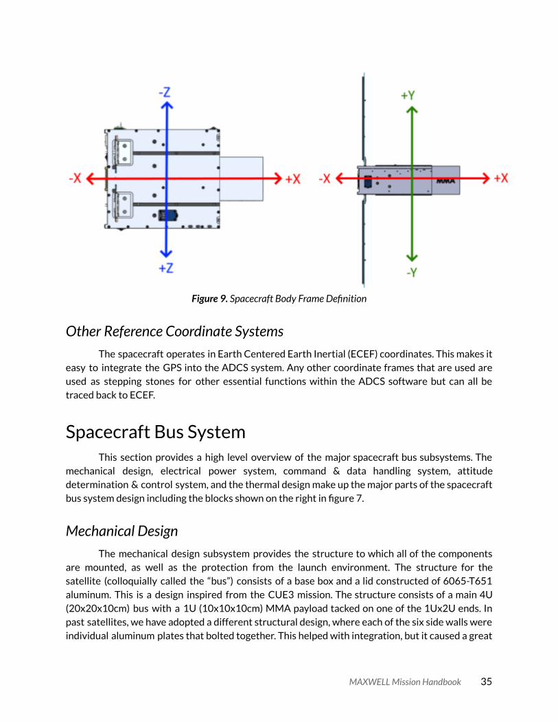
Figure 9. Spacecraft Body Frame Definition
Other Reference Coordinate Systems The spacecraft operates in Earth Centered Earth Inertial (ECEF) coordinates. This makes it
easy to integrate the GPS into the ADCS system. Any other coordinate frames that are used are used as stepping stones for other essential functions within the ADCS software but can all be traced back to ECEF.
Spacecraft Bus System This section provides a high level overview of the major spacecraft bus subsystems. The
mechanical design, electrical power system, command & data handling system, attitude determination & control system, and the thermal design make up the major parts of the spacecraft bus system design including the blocks shown on the right in figure 7.
Mechanical Design The mechanical design subsystem provides the structure to which all of the components
are mounted, as well as the protection from the launch environment. The structure for the satellite (colloquially called the “bus”) consists of a base box and a lid constructed of 6065-T651 aluminum. This is a design inspired from the CUE3 mission. The structure consists of a main 4U (20x20x10cm) bus with a 1U (10x10x10cm) MMA payload tacked on one of the 1Ux2U ends. In past satellites, we have adopted a different structural design, where each of the six side walls were individual aluminum plates that bolted together. This helped with integration, but it caused a great
MAXWELL Mission Handbook 35
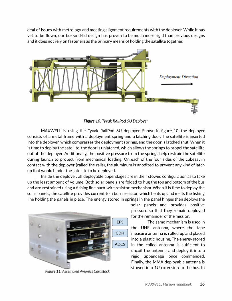
deal of issues with metrology and meeting alignment requirements with the deployer. While it has yet to be flown, our box-and-lid design has proven to be much more rigid than previous designs and it does not rely on fasteners as the primary means of holding the satellite together.
Figure 10. Tyvak RailPod 6U Deployer
MAXWELL is using the Tyvak RailPod 6U deployer. Shown in figure 10, the deployer consists of a metal frame with a deployment spring and a latching door. The satellite is inserted into the deployer, which compresses the deployment springs, and the door is latched shut. When it is time to deploy the satellite, the door is unlatched, which allows the springs to propel the satellite out of the deployer. Additionally, the positive pressure from the springs help restrain the satellite during launch to protect from mechanical loading. On each of the four sides of the cubesat in contact with the deployer (called the rails), the aluminum is anodized to prevent any kind of latch up that would hinder the satellite to be deployed.
Inside the deployer, all deployable appendages are in their stowed configuration as to take up the least amount of volume. Both solar panels are folded to hug the top and bottom of the bus and are restrained using a fishing line burn-wire resistor mechanism. When it is time to deploy the solar panels, the satellite provides current to a burn resistor, which heats up and melts the fishing line holding the panels in place. The energy stored in springs in the panel hinges then deploys the
solar panels and provides positive pressure so that they remain deployed for the remainder of the mission.
The same mechanism is used in the UHF antenna, where the tape measure antenna is rolled up and placed into a plastic housing. The energy stored in the coiled antenna is sufficient to uncoil the antenna and deploy it into a rigid appendage once commanded. Finally, the MMA deployable antenna is stowed in a 1U extension to the bus. In
MAXWELL Mission Handbook 36

the deployer, there are specially-designed rail extensions on the MMA payload that help direct the load path of the deployment springs across the length of the satellite. At the end of the mission, when it is time for the MMA antenna to be deployed, there is a small motor that actuates and unfolds the antenna like a lotus.
A final important mechanical feature is the avionics cardstack or cardbus. This is an enclosure that rigidly contains the ADCS, EPS, CDH, and Backplane (BP) electrical PCBs. The cardbus is designed so that the three avionics boards are able to easily slide in and out of the BP which provides for some easy integration as the electrical PCBs have their design iterated. Figure 11 shows the cardstack assembled and calls out the positions of the boards.
Electrical Power System Design EPS is the power management system of the satellite. It is responsible for power regulation
and distribution as well as battery charging and discharging. The EPS also has a robust inhibit scheme which prevents energy from leaving the battery while the spacecraft is stowed in the deployer. This system is reliant on both careful hardware and software choices to fill its role in the satellite system.
On the hardware side the EPS system uses combinations of buck and boost converters to supply the satellite system with regulated 12V, 5V, and 3.3V power from the batteries and/or the solar panels. The EPS is housed in the card stack and is thus integrated directly with the backplane to supply power to the ADCS and CDH cards directly. The EPS board also supplies various bus power voltages to components throughout the bus through harnessing that connect directly with the backplane board. A single designated point is chosen for spacecraft ground and it attaches directly to the bus structure. All ground lines run back to this single point to avoid potential ground loops in the flight system.
The EPS software is hosted on a dsPIC32MZ2048EFG100 manufactured by Microchip. The EPS software monitors critical voltage and currents of all the bus power lines as well as the temperatures of the battery. The battery state of charge is also monitored. These values are stored in the EPS HK packet and transmitted to the CDH to inform the spacecraft mode. An MPPT algorithm is planned to be implemented on the EPS system to help close the power budget and maximize the efficiency of the EPS buck converters to minimize power waste on the satellite.
Command & Data Handling System Design The Command and Data Handling Subsystem is the brain of the CubeSat. It is capable of
receiving and transmitting data from all other subsystems of the CubeSat. It is also capable of making decisions and commanding subsystems based on data received and the sensed state of the spacecraft. The five primary tasks of the CDH system are listed in table 19.
MAXWELL Mission Handbook 37

Table 19. CDH System Primary Tasks
CDH Task
Send & receive commands from all subsystems
Collect HK data from all subsystems
Send data to the Lithium for transmission to the ground station
Interpret commands from the Lithium that were sent from the ground
Change the spacecraft mode based on the battery state of charge
The C&DH board has a dsPIC33 microcontroller as the primary processor. It uses a 16 bit
dsPIC33EP512MU810 to interface with various hardware peripherals with minimal external components. The C&DH uses a variety of communication interfaces to talk to the other subsystems, memory and sensors. Four UART lines are used to communicate with the EPS subsystem, the ADCS subsystem, the PLDC, and Lithium radio. Four SPI lines are used to communicate with the two SD cards, the Simplex beacon radio (GlobalStar), GSE UART output. The PIC also includes an internal analogue to digital converter (ADC) to sample thermistors used to sense temperatures in the bus. Several of the GPIO pins set status LEDs and set physical enable flags for tasks such as enables for the burn resistors, battery heater, and T-DaHGR deploy enable.
Mode switching is the most important task for the CDH subsystem. It is an algorithm used to ensure satellite survival if critical battery state of charge conditions are encountered. The CDH subsystem uses the SoC obtained from EPS to determine what mode to put the satellite in. The spacecraft has six defined modes which are listed in table 20. The best reference document for the operation of the CDH subsystem is the CDH State Diagram (previously the State Diagram Outline ) which describes how all of the spacecraft operating states are connected and what the entry and exit conditions are for each spacecraft mode. This diagram also has flowchart elements that show the decision tree and processes for every transition of the CDH system, and thus the flight system.
Table 20. CDH Spacecraft Modes
Spacecraft Mode Mode Description
Sleep
This mode is only used once during the mission. It is the initial spacecraft state that begins right after the spacecraft is ejected from the deployer. In this mode only a 45minute timer is active which blocks all other spacecraft functionality until it expires.
Commissioning
This mode is activated directly after the Sleep state is terminated by the 45minute timer when it expires. Commissioning mode means the satellite will communicate with the ground to do initial systems checkout so that the ground
MAXWELL Mission Handbook 38

team can prepare the spacecraft for the mission.
Phoenix
This mode is for when the spacecraft state of charge transitions below 60%. In this mode all potential power is conserved and only the CDH and EPS systems remain active. The satellite is presumed to be able to charge while tumbling in this configuration enough for it to transition back out of Phoenix mode when the state of charge reaches 65%.
Safe
This mode occurs when the state of charge is greater than 60% and there has been a spacecraft error. Safe mode will try to maintain a power positive orbit attitude and still enables communications with the ground so that the ground team can try to resolve the spacecraft error and try to determine what happened.
Nominal For all intents and purposes nomina mode is very similar to safe mode except the state of charge is greater than 80% and a few more things can be turned on for spacecraft operation.
Science
This is a special mode and will most likely have sub modes based on the science being conducted. The technology demonstrations with the radios will each have their own mode within science as well as the CSAC experiment and T-DaHGR demonstration.
Lithium Radio The Lithium radio is a UHF/VHF transmitter and receiver that is built and developed by
AstoDev LLC . The radio is configurable and has flight history on previous missions which makes it a good choice for MAXWELL’s TT&C communications. MAXWELL uses the Lithium in the UHF band and manufactures a custom UNF tape measure antenna which is deployed after the satellite exits from sleep mode following ejection from the deployer. The tape measure antenna has a nearly circular gain pattern which enables TT&C communications from nearly any attitude.
Attitude Determination & Control System Design The MAXWELL ADCS subsystem is designed to be able to sense and control the attitude
and position of the spacecraft such that it is capable of completing the mission objectives. The full system is custom built for the mission and uses actuators purchased from external suppliers. The ADCS system also has the bandwidth to manage the CSAC Experiment.
The center of the ADCS subsystem is a custom electronics board that connects all the components of the ADCS subsystem together. This electronics board is connected directly into the cardstack and routes all signals directly into the processing unit that manages all the ADCS system tasks. Due to the complexity of the processing required for the ADCS subsystem it was unsuitable to choose a microcontroller. Instead a BeagleBone Black Industrial (BBB), a pocket
MAXWELL Mission Handbook 39

computer similar to a Raspberry PI but slightly more powerful, was chosen as the central processing unit to manage all system tasks.
The BBB runs a custom bare bones Linux Kernel and operating system which is hosted on a binary executable that is compiled with a specialized 2012 GCC compiler on an external platform. The binary executable is stored on a removable SD card and prior to flight a bare bones version of the software with high confidence is also loaded onto the flash memory for use in the event that the binary executable file is corrupted while in flight. The system also has the ability to upload a new binary executable to the SD card through the TT&C link while flight operations are ongoing.
Attitude determination is done using a Least Squares estimation using data from up to 16 photodiode sensors oriented in various directions around the spacecraft as well as up to three magnetometer solutions. The QUEST algorithm is also available for a finer attitude determination solution. An extended kalman filter (EKF) is also in the works but has not yet been implemented. The system also has three control algorithms available. Bdot is the primary algorithm used for detumbling the satellite and for momentum management. The satellite also has PD and PID control loops available depending on the degree of pointing accuracy required. Operations like sunpointing do not need to be as precise with attitude control as experimental communications passes.
The ADCS system includes a pyramidal set of reaction wheels manufactured by NanoAvionics, a space company based in Lithuania, and three orthogonal magnetorquers manufactured by CubeSpace, a space company based in South Africa. The four photodiode pyramids each contain four photodiodes and offer views of the sun from all but one face of the CubeSat. There are three tri-axis magnetometers on the system, one on the main electronics board in the card stack and one on the outer edge of each solar panel. The onboard electronics board also has redundant tri-axis gyroscopic sensors. Finally, a NovAtel OEM279 GPS receiver is integrated into the system to provide GPS timing and range data.
Thermal Considerations Modeling the thermal behavior of the system is critical in order to be able to understand
how it will behave on orbit. There are three stages of the modeling process that occur on the MAXWELL project. The first is to develop the thermal model using the Thermal Desktop software package. This allows all the components and the satellite structure to be put through different virtual orbits in order to estimate the thermal performance of the system and see if the temperatures of the components remain within their operational range. This is an initial first pass at a viable thermal model of the system and gives insight into expected orbital scenarios which can inform the design effort as it continues.
The second stage of this process starts with a complete initial thermal design. With a mature thermal design then the conductivities of critical components along expected heat paths can be verified by testing them with engineering versions of the flight components. Verifying the conductivities at critical points in the spacecraft bus helps further inform the model and refine the estimated conductivities that were used to create the initial complete thermal design. WIth the addition of verified conductivities from testing the thermal model becomes mature and is ready for stage three.
MAXWELL Mission Handbook 40

The third stage involves planning and executing a thermal vacuum test. In thermal vacuum the satellite will undergo hot and cold cycling through the extremes of the temperatures expected on orbit. This will not only stress the system representing an actual orbit but there will also be a great deal of data collected about the temperature response of the satellite. These will be a final test where the conductivities in the model can be adjusted to match the thermal vacuum response. When the thermal model behaves like the flight system in thermal vacuum then there is substantial confidence that the model well represents the flight system and can be used with data collected on orbit to accurately estimate the thermal state of the satellite.
The thermal model is also critical for selecting flight surface coatings. For the selection of coatings to be accurate the thermal model should be reaching the mature state. This will also help inform hot/cold transition times during the thermal vacuum test. MAXWELL has considered bare aluminum and silver teflon as surface coatings, but as the model has progressed to the mature design state, silver teflon (on all surfaces) is the current preferred coating due to the cold-bias it provides to most components. The temperature ranges of critical components like the batteries which have the tightest temperature range are what drive the selection of surface coatings.
Spacecraft Payload Systems This section provides high level details about the subsystems operating in the spacecraft
payloads. These systems are shown in the high level block diagram in figure 7 in relation to the other bus subsystems and the rest of the spacecraft.
Payload Computer Board The PLDC is a secondary microcontroller that is solely in charge of managing the
communications experiments for the S-band, X-band, and T-DaHGR mission objectives. The microcontroller chosen is a dsPIC32MZ2048EFG100 manufactured by Microchip. The PLDC receives commands from CDH to initiate any of the five communications demonstrations. The PLDC electronics board interfaces directly with the S-band electronics board and also provides power to the CSAC component but routes all other interfacing from the CSAC directly through the backplane to the ADCS board.
X-band Transmitter The MAXWELL experimental X-band downlink will leverage the successful collaboration
between the University of Colorado Boulder and Blue Cubed to develop a CubeSat compatible high rate X-band communication transmitter, the XTx. The XTx is a direct convert software defined architecture using an offset quadrature phase shift keying (OQPSK) modulation scheme and single chip vector modulator. The XTx design includes a FPGA that provides the interface to the flight computer and drives the vector modulator with the required in-phase and quadrature data stream.
MAXWELL Mission Handbook 41

The output RF signal from the vector modulator is filtered and amplified before transmission. A voltage controlled oscillator block has also been implemented to stabilize the transmitter oscillator. The software defined architecture of the XTx with the FPGA driving the vector modulator allows the development of forward error correction software and CDMA capability. On MAXWELL the XTx will be capable of transmitting up to 30Mbps with a 1E-7 bit error rate. The XTx transmits using a feedhorn antenna that was designed and developed for the University of Colorado Earth Escape Explorer (CUE3) mission.
In the context of the MAXWELL system the XTx provides the transmission signals for both the feedhorn and T-DaGHR antennas. The feedhorn antenna is used for the X-band downlink and X-band CDMA technology demonstrations while the T-DaHGR is singled out for MO6. The C&DH system does not directly communicate with the XTx and instead this responsibility is left up to the Payload Computer (PLDC). This helps distinguish spacecraft operations in an experimental mode from a nominal or safe mode. The PLDC is responsible for initiating the X-band experiments using the XTx as the transmitter and also is able to pipe data it has collected from the rest of the system into the XTx for transmission should it be necessary.
S-band Receiver The S-band receiver consists of an S-band patch antenna which feeds into a
direct-conversion radio. After a signal is received by the antenna, it is fed through a series of filters that reject out of band power. The signal is then amplified by two low-noise amplifiers (LNA) and fed into the RF port of an IQ mixer. The mixer splits the signal into I (in-phase) and Q (quadrature) signals which are sent to a pair of differential amplifiers and then sampled by an analog-to-digital converter.
After the signal is digitized then a low power FPGA, currently selected to be the Microsemi Igloo 2, performs the carrier signal acquisition and demodulation to pull the data transmitted. The FPGA then interfaces with the dsPIC on the PLDC to transfer the data to the PLDC for storage. This data is eventually transmitted via the UHF TT&C link back to the ground for analysis to confirm experimental functionality.
Chip Scale Atomic Clock The CSAC experiment is designed to characterize the Allan deviation of the CSAC
component while on orbit. This is of interest to many players in the DoD and the design of the experiment is being spearheaded by the CONTACT graduate project team at the University of Colorado under the direction of Professor Penina Axelrad. This experiment is hosted as a payload on the MAXWELL mission and the data it generates is sent to the ground via the UHF TT&C link for analysis by the CONTACT team.
MAXWELL Mission Handbook 42

Ground Systems There are three major ground systems that the MAXWELL mission requires. The first is a
UHF system which will be the primary means of communication from the ground operations team to the satellite. The UHF system will be for TT&C and some experimental data downlink. MAXWELL will also require a S-band uplink station and an X-band downlink station to perform the communications demonstrations for MO-1, MO-2, MO-3, and MO-4.
UHF Ground System The UHF ground system supporting MAXWELL uses the LASP UHF ground station and will
handle all UHF TT&C and handle outgoing commands and incoming data packets from MAXWELL. Data from MAXWELL will be downlinked primarily via the LASP UHF ground station and then copied to both the CU data processing team and to a MAXWELL server. The LASP ground station will not only support routine downlinks for MAXWELL’s housekeeping data but will perform commissioning operations and provide troubleshooting operations should the need arise.
The UHF RF chain has been modernized since QB50 to operate using an SDR. This replaced the radio transceiver and TNC setup used for QB50 with an Ettus Research B200 SDR. The rest of the RF chain has not been changed and is shown in figure 12.
Figure 12. LASP UHF RF Chain
MAXWELL Mission Handbook 43

The LASP UHF RF chain operates on half-duplex (non-simultaneous up/downlink) and has a set of two of UHF Yagi antennae (of the same model) to balance the rotator.
The specifications for the ground station are shown in table 21 and allows the command uplink to meet or exceed a link margin of 28.15 dB and a data response downlink link margin of 14.15 dB.
Table 21. LASP UHF ground station specifications
Location
Latitude 40.00877
Longitude -105.2476
UHF Transceive Properties
Transmit/Receive Frequency Range 430 - 438 MHz
Polarization RHC & LHC
Pointing Accuracy 7.2°
Gain 18.95 dBi
EIRP 27.0 dBW
Hydra is a highly configurable telemetry and control software for CubeSats, created by
LASP. It has the ability to handle bit-level telemetry and commands, display and monitor data as well as support multiple decoders and hardware devices. Data comes in through hardware and is formatted by a Reader as a frame. The Reader then sends the frame to a Decoder that decodes the bytes into individual items and populates an Item Database. User-configured display pages can then read from the database and display the data, raw or calibrated according to types,
dictionaries or conversions. Hydra is also able to send commands in the form of a binary frame, which is passed to a decoder to send off to a hardware device like a radio. Decoders can be chained together to allow for the parsing of complicated packet formats. This allows for multiple telemetry and command paths depending on the use.
A command excluding the CCSDS primary and secondary headers (12 bytes), and AX.25
MAXWELL Mission Handbook 44

header (14 bytes) is at minimum 16 bytes long and at most 256 bytes long. This gives an average packet length of 136 bytes or 162 bytes if including the headers. All UHF communication will occur at a data rate of 9600 bps. This means that sending one command from the ground network to MAXWELL will take at least 35 ms (16 byte command with AX.25 and CCSDS headers) or at most 235 ms (256 byte command with AX.25 and CCSDS headers. Thus the average command packet would take 135 ms to fully transmit.
A typical command (like the issue housekeeping command packet) has 14 bytes of the CCSDS primary and secondary headers, followed by the opcode (0x18) and any arguments, none in this case so the unused bytes will be padded with 0’s. Typically there would be a CRC checksum appended at the end of the packet to validate the integrity of the command packet. Instead, AES-128 GCM encryption will be applied to the command section of all command packets which will provide both confidentiality and data integrity (authentication) which removes the need for the checksum.
Most of the commands are nominal, in that they don’t need permission from the PI to transmit. Non-nominal commands however, do. As of writing, no commands have been officially set as non-nominal but Hydra has the capability to protect commands with a prompt that must be confirmed before sending.
A typical day-in-the-life of a ground station operator will involve waiting for a ground pass and depending on which phase of the mission MAXWELL is in, will act accordingly. During commissioning, a ground station operator will be in charge of deploying MAXWELL’s comms equipment and solar panels as well as monitoring MAXWELL’s subsystem statuses to make sure that nothing is off. In the experiment phase, the ground station operator will transmit a command to MAXWELL to start a specific experiment. This will involve either transmitting bytestreams to MAXWELL or receiving telemetry (either housekeeping packets, orbital data packets, or science data packets/bytestreams) from it.
S-band Ground Station The S-band ground system will be provided by a commercial ground station provider which
has not been chosen at this time. S-band FCC licenses are notoriously difficult to acquire so it is highly unlikely that LASP will get one in order to be able to use their S-band station. This fact pushes the MAXWELL team to work with a commercial provider to perform the S-band communications demonstrations.
X-Band Ground Station The X-band ground station used for the mission will also be owned by a commercial ground
station provider. The MAXWELL team applied for a DUHRIP grant in 2019 to purchase an X-band ground station but did not receive the funding so the team will turn to a commercial provider for these services. A commercial provider has not been identified at this time.
MAXWELL Mission Handbook 45

Programmatics The programmatics on the MAXWELL mission have evolved significantly since the
inception of the project. Each iteration of the programmatics was largely dominated by the project manager in charge at the time with little input from the PI or advisors. This led to a rather disjointed approach to project management which was not ideal. The culture of programmatics is important to establish from the beginning in order for the entire team to buy into it, otherwise changing the programmatics, even if it is an improvement, is extremely difficult.
Document Tracking and Official Releases The process for tracking and releasing official documents is critical to maintaining project
knowledge and documentation over the lifetime of the project. Transitions in personnel and simply not tackling a task for an extended period of time lead to knowledge gaps that can grow significantly if there is no central tracking of official documentation. Additionally, since leadership on the project changes from time to time the location of documents with important information regarding a subsystem or a task can be lost to the ether of the google shared drive if persons who wrote that documentation move off of the project.
Establishing a centralized document tracking and release procedure helps to mitigate the loss of information about the system. The MAXWELL document tracking system is centralized in a single document that establishes the following for each tracked document. Table 22 Below describes the fields tracked for each document in the 0001 Document Numbering and Tracking which is the complete list of all tracked documents on MAXWELL.
Table 22. Document Tracking Attributes
Document Attribute Attribute Description
Document Number
This is a unique identifier for every tracked document. As documents are added to the official tracker they are each assigned the next available number. The title of each document that is tracked is also assigned the four digit unique tracking number. Officially released documents are also prepended with this same four digit number in addition to the document specific revision number as described in the second to last entry in this table.
Document Type
This identifier puts the document into a broad group of documents under the MAXWELL project umbrella. These identifiers are:
● Organizational - Documents that contain information that is relevant at the project level.
● Proposal - These are strictly proposal documents ● Technical - These are documents that contain technical
MAXWELL Mission Handbook 46

information relevant to a specific subsystem or selection of subsystems.
● Tracking - These are strictly tracking documents that keep track of hardware used on the project which includes flight, engineering, and lab hardware
● Test Report - This identifier is associated strictly with test results and report documents. If a test is performed then it generates an official test report which must be tracked for requirement verification.
● ICD - This identifier stands for Interface Control Document which is a critical class of documents so that subsystems on the satellite can define their interface in one single place and align their design and work efforts.
Related Subsystem
This field provides a subsystem specific category for a tracked document. Multiple subsystems can be listed in this column as appropriate for the specific document tracked. This marking is under document type umbrella as it is more specific.
Document Description
This is a very important field as it provides a concise yet detailed description of the document that is tracked. It should be written such that if someone is searching the tracking document if a ctrl+f search then they should probably be able to find that document’s line if they are looking for the information that would be contained within that document.
Document Keywords
This is an additional field that is similar to the description but attempts to slightly more broadly detail what information might be included in that document. This field is again meant to be useful for someone trying to find documents by doing a ctrl+f search of the google sheet.
Working Document Link
This is a link to the WORKING DOCUMENT . This should always be a Google Docs, Google Sheets, or other Google document format link. The goal here is that there is ever only a SINGLE working document that always gets updated. Do not make copies of documents or start new documents if you can simply update one that already exists. Releasing new revisions is how we track document history, not by creating new working documents.
Latest Official Release Number or Date
This field contains two different pieces of information depending on the Document Type field of that tracked document. If the tracked document is a Test Report, then this field is a running list of dates that that official test was performed. For all other document types this field contains a single reference to the most recent official revision of that document. This number is in the
MAXWELL Mission Handbook 47
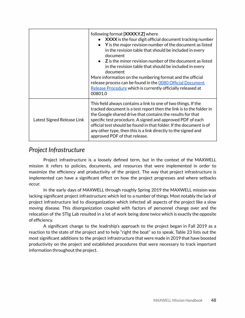
following format [XXXX.Y.Z] where ● XXXX is the four digit official document tracking number ● Y is the major revision number of the document as listed
in the revision table that should be included in every document
● Z is the minor revision number of the document as listed in the revision table that should be included in every document
More information on the numbering format and the official release process can be found in the 0080 Official Document Release Procedure which is currently officially released at 00801.0
Latest Signed Release Link
This field always contains a link to one of two things. If the tracked document is a test report then the link is to the folder in the Google shared drive that contains the results for that specific test procedure. A signed and approved PDF of each official test should be found in that folder. If the document is of any other type, then this is a link directly to the signed and approved PDF of that release.
Project Infrastructure Project infrastructure is a loosely defined term, but in the context of the MAXWELL
mission it refers to policies, documents, and resources that were implemented in order to maximize the efficiency and productivity of the project. The way that project infrastructure is implemented can have a significant effect on how the project progresses and where setbacks occur.
In the early days of MAXWELL through roughly Spring 2019 the MAXWELL mission was lacking significant project infrastructure which led to a number of things. Most notably the lack of project infrastructure led to disorganization which infected all aspects of the project like a slow moving disease. This disorganization coupled with factors of personnel change over and the relocation of the STIg Lab resulted in a lot of work being done twice which is exactly the opposite of efficiency.
A significant change to the leadrship’s approach to the project began in Fall 2019 as a reaction to the state of the project and to help “right the boat” so to speak. Table 23 lists out the most significant additions to the project infrastructure that were made in 2019 that have boosted productivity on the project and established procedures that were necessary to track important information throughout the project.
MAXWELL Mission Handbook 48

Table 23. Project Infrastructure Systems
Infrastructure System Description
GitLab
A software change tracking system with the equivalent functionality of GitHub. This system allows anyone on the software team or the leadership to track software changes and additions from a central location. It is a lot more transparent than the previous system and will be easier to encourage incoming students to use regularly.
Electrical Board Tracking
A system where each and every electrical printed circuit board has its own tracking sheet. This sheet keeps track of the board’s location and status from receiving to flight integration. This offers accountability for the location and use of each board through its lifecycle and also a way to track anomalies and other notes on the board. Each board on the MAXWELL project is given a unique serial number identifier that is permanently marked on the board and which matches with this sheet.
Test Kit Tracking
Each test kit now has a tracking inventory list that keeps track of everything in each test kit. This helps prevent items from being lost between tests and ensures that repeatable equipment is used in every test. All test kits are logged in and out of use for further accountability.
Software Ticket System
This system tracks issues in software and is also managed through the GitLab interface. Team members assign a software issue (essentially issuing a ticket) such as a bug to correct or feature to implement through the GitLab interface in order to make sure that it is tracked somewhere. This helps leave a paper trail for features that are implemented and bugs that are solved in software.
Hardware Ticket System
This system is similar to the software ticket system but is instead embedded in the team’s Slack platform. Through this any hardware issues are tracked. Just like the software tickets, these issues can be bugs to fix or features to be implemented. This helps leave a paper trail for everything that is fixed and changes that are made in hardware.
Labels
Everything that goes into the STIg Lab geets a label. The item itself is labeled, the box it’s in is labeled, and the cabinet that box is in is labeled. This makes it easy for anyone to go around and locate what they are looking for and it also helps people put things back in the right place.
MAXWELL Mission Handbook 49

Review Culture
A culture of reviewing changes is implemented as well. This would have been much more effective to have in the beginning, but now folks are not hesitant to reach out to the advisors for input. This helps the leadership (PI and advisors) to remain more involved which in turn helps motivate students more.
Waterfall Charts
Waterfall charts turned out to be a good way for leadership to track the tasks that students were working on at the subsystem level. These provide a graphical visualization of when tasks are estimated to be completed, their current status, and ultimately if they become pushed back or are completed later than expected. Having regular waterfall chart reviews (typically this cadence is roughly every two weeks) helps keep students on track and also helps management make sure that students are pushing forward the right tasks and not getting sidetracked by tasks that are unimportant. It is important for leadership to remind students periodically that they need to keep their waterfall chart updated to get the maximum value out of the time spent on maintaining these through the semester.
Some of these project infrastructure additions may seem like extra paperwork or
busywork but be assured they are absolutely critical to success on the project. Without these measures to track changes, issues, and features in all parts of the project things get missed. When these were not implemented before Fall 2019 things did get missed and work had to be repeated over and over again because of the severe lack of documentation. These project infrastructure improvements seek to change the culture of working on the project to be focused on maintaining a body of knowledge about the project that previously got lost each semester when people transitioned off the project and new folks transitioned on.
Personnel This is a critical aspect of the MAXWELL project. The nature of being a graduate project at
the University of Colorado makes getting work done at a steady pace extremely difficult due to the natural personnel transitions supported by the course. Since the course is set up to support usually a two consecutive semester track each academic year there usually is a group of new students that joins each semester. One of the perks of being part of this course is that there are usually a few new recruits each semester.
There are, however, a number of disadvantages to the graduate projects approach. In past years, getting graduate students to be interested in taking graduate projects has been difficult because only a subset of graduates are interested in doing project work. There are also a lot of other projects competing for personnel as well, and with a limited interest pool this makes it even
MAXWELL Mission Handbook 50

less likely that one project will be able to meet the staffing needs from just the pool of aerospace graduate students interested in projects.
To try and supplement the trickle of students that get involved through enrollment in the course itself it is critical to actively recruit students from other departments. The Electrical Engineering department typically has students with the most useful skill sets in the context of satellite systems because they are prepared for electrical board design, RF, and embedded software which are critical for a satellite to function as desired. In most cases it is possible to recruit a few students each semester directly from the EE department. This is usually done by word of mouth from current EE students working on the project and by making contacts within the department that can help spread the word.
There is also a great value to adding motivated undergraduates to the team. Undergraduates tend to have less dedicated time than graduate students to contribute but also are looking for something legit to put on their resume. Participation on a real flight quality satellite certainly says a lot and this tends to attract undergraduate students who are trying to compete for internships and need something to stand out above the rest. Motivated undergraduates who stay with the project long enough should be given an opportunity to lead and get compensated as well. In some cases an undergraduate student who has been with the project for a year or two might contribute more than a graduate student who is new on the project because they can produce work year round while new graduate students spend a lot of time onboarding onto the project which distracts students trying to get work done at the same time.
Recruitment Recruitment is also critical to the success of the project. Not only is it enough to have good
people but a constant effort that is required in order to keep roles on the team filled. Recruitment can make or break a semester which can quickly make or break a year which has significant implications on the ability for the project to meet deadlines and avoid creating large knowledge gaps.
The recruitment strategy on this project has evolved significantly over the lifetime of the project. In early years of the project, there was naturally more interest in the project because of a smaller Graduate Projects section which meant more students were involved in the project by default of there being a limited number of projects for students to choose from. This probably eased the recruitment necessary to maintain full staff levels in early years of the project.
As the Graduate Projects section expanded to include more projects this unintentional boost to recruitment was lost and it became more difficult to maintain full staffing levels simply because there were more choices for students who were enrolled in Graduate Projects. This prompted some first order recruitment efforts that included posting flyers around the engineering buildings and holding an “Info Session” each semester to try and attract prospective students to the project. This strategy was marginally successful and depended a lot on hoping that students didn’t have conflicts the day of the info session or even got the information about it in the first place.
The project has also aggressively targeted students in the Electrical Engineering department or with an EE background because of the need for students with skills in power
MAXWELL Mission Handbook 51

systems and embedded systems design. Students with an Aerospace background typically do not have sufficient skills in these areas to design, build, and implement the customized EPS and embedded hardware and software design from scratch. It has happened in the past and I’m not discounting it, but statistically EE backgrounds give students a head start in these major sections of the project.
Starting in the spring of 2019 the project moved to a more targeted approach to recruiting that has been refined over three semesters and has brought a number of excellent students onto the project and kept staffing at high levels. Targeted recruiting for MAXWELL involves adding some additional avenues that help reach broader groups of students in order to generate interest in the project. The targeted approach started with requesting that the graduate advisors send out an email on behalf of the MAXWELL team reminding students that registration was coming up and that MAXWELL was looking for students interested in filling a number of roles with various descriptions that were provided in the communication.
As operations shifted to the new Aerospace building, additional improvements to the targeted recruitment strategy were made. Table 24. describes the most effective recruitment strategies to date on the MAXWELL project.
Table 24. Most Effective Personnel Recruitment Strategies
Strategy Description
Graduate Projects Recruitment Session
This is an event sponsored by the Graduate Projects Coordinator (previously Dr. Nick Rainville) that is held usually right before or right as registration opens up for courses the following semester. This is a major event on the recruitment calendar because there is typically a lot of interest because information about the event has been emailed out to all the graduate students many times prior to it to try and pick up the most interest as possible. Additionally, there is a lot of pizza involved and that tends to draw crowds too. It is important that the presentation (~5min) given at the event is really good because this is one of the only times that students will be able to directly assess the “fidelity” of MAXWELL in the context of all the graduate projects. If the MAXWELL presentation is solid, a little funny, is very direct about the kind of roles that are available, and looks like the most put together presentation then this will be a successful event. This event should be geared toward Aero students.
Personal Word of Mouth
This can be a very powerful recruitment tool, especially for students in departments that are not the Aero department. Students from other departments that are working on the project should be encouraged to encourage their friends to join the project as well. This will help keep students on the project for longer and also get their friends on the project which is great for productivity of the veteran member and also
MAXWELL Mission Handbook 52

the new member. Additionally, if students hear about how fun working on the project is from their friends they will be more interested than if they just heard from some email that working on this project is fun.
Emails & Follow Ups
If students email you about being interested in the project make sure to get the project manager and the systems engineer onto the email chain. Ask them for a resume and make sure to not forget about their email. Respond to these at least within 24hrs because the faster a response from us is the more likely the interested student will remain involved. Also do not be afraid to send follow up emails if you haven’t heard from an interested student in a few days. Always offer a lab & hardware tour to students who are interested because it will get them excited to be more involved in the project if they feel like they understand a bit about how it works. Remember that saying, “the devil that you know is better than the devil you don't”. Be honest with what the expectations are and make sure you and them are talking about the same role on the project.
Thinking Ahead & Getting Advisors Involved
By the middle of each semester you should know or at least have a good idea about what the roles you need to fill are because that will help inform your targeted recruitment efforts. Make sure to bring the project advisors into the conversation since they can help navigate some of the channels and also can provide an important perspective on where they feel the personnel needs are.
Social Media and University Communications
This is something that doesn’t get a ton of recognition but is something that we can take advantage of. First off, MAXWELL has its own Twitter account which can be a good motivator to take photos of team members working in the lab and also to highlight accomplishments of team members on the project (however minor) which can be both good motivation and good visibility as people probably follow the twitters of their friends. The Aerospace department also has its own communication team which can help raise the visibility of MAXWELL on department communications. Think of it this way, the more people that see the name MAXWELL the better because it’s a numbers game at the end of the day.
Team Motivation & Success Team motivation is something that should be approached from a few different angles and it
is a very important part of staying on track and getting quality work done. The most important way to motivate the team is to lead by example. If the leadership on the team works hard then the team
MAXWELL Mission Handbook 53

members will work adequately. If the leadership works very hard, then the team members work hard. And if the leadership drops 30-40hrs a week into the project then everyone else on the team will feel like they need to contribute more just to keep up. It;s a bit of a slippery slope for the leadership but setting the standard very high will make the rest of the team not only respect you a little more but also want to work a little bit harder than they might otherwise to get some recognition. This is a difficult thing to sustain as leadership but it can pay lots of dividends.
It's also important for the PI to be seen regularly by the team. If the PI is involved regularly then this lends an extra aspect of officiality to the project and provides some external motivation because they are seen as the head honcho by everyone. Even if it’s just a couple times a semester, having the PI directly address the students is great for morale and it helps extend the context of the project beyond just being a course that they are taking for a grade.
Another way to best motivate a team is to be able to set out clearly defined tasks and deadlines. This is really important because it makes it clear to the team members exactly what the leadership is looking for. If everyone on the team knows exactly what they have to do and they don't have to think too hard about it then they spend more time actually doing things to push the project forward instead of trying to figure out what to do. Also part of this is being very available on the leadership side to answer questions and provide guidance when asked. As the project manager or systems engineer being highly available on Slack or email is imperative. The faster you can answer someone’s question the faster they can get back to work.
Finally it’s very important to be proud of your team. For the most part students are putting forth their best effort and that should always be commended. It is great to publicly acknowledge exceptional work done by a team member as it rewards them and helps motivate others. As leadership you should not be too easy to please, but you should not set your standards so high that no one will ever come close to meeting them.
Buy In This is one of the trickiest parts of the whole project: figuring out how to get the team to
buy in to the policies, procedures, documentation, and processes that have to be in place in order for the project to succeed and remain on track. The easiest way to get buy in is to have these policies, procedures, and tools implemented from the beginning. If these things crop up slowly as the project continues then people will see them as a new task that they didn't have to do previously but now need to. This makes them less inclined to deal with doing it and if there is not enough pressure from the leadership to get it done right then it won’t get done at all.
Tasks & Schedule One aspect of the project that was historically difficult is task management. Some
platforms were introduced in the past and subsequently fizzled out because there really was no buy in from the team (see the next subsection for additional discussion). To change this trend there needs to be more pressure on task tracking created from the project leadership. If the leadership pushes hard for task tracking then eventually folks will buy in, but there needs to be constant, ever present pressure from the leadership team.
MAXWELL Mission Handbook 54

Systems engineers are well suited for being the shepherds of task tracking because they have a good understanding of the tasks that each subsystem needs to do and how tasks relate to one another. Task tracking should be managed by one or two people and no more. The task tracking should also line up with the tickets for both hardware and software. This combination of creating tickets and tracking tasks could be effective because folks that get a task assigned to them are notified and clear on what needs to be done and those tracking the tasks can keep people focused on the critical path instead of wandering off on tangents.
Onboarding Process Onboarding is a critical task that has to be performed each semester regardless of how
well everything is planned out. Each semester there are new students and it is a significant effort on behalf of the team to onboard them so that they can begin to contribute to overall progress on the project. In the past team members who were already in the loop effectively stopped their work to onboard new students. This took anywhere from a few weeks to a few months depending on the subsystem and the level of involvement from the new students.
Typically it takes a new student an entire semester of getting by to start to be able to determine the next steps that need to be taken on their own. This makes it very difficult to get a lot more than just one semester of productive work from people which contributes to slow progress on the project. The strategy employed moving forward is to have short, single week tasks available at the start of each semester that can be immediately handed off to incoming students. This will give them something to do that is useful to the project and which also doesn’t require a full understanding of the system at hand. This full understanding will be something that they gain while shadowing other students who are working on broader picture tasks.
STIg Lab Onboarding & Access The process for getting access to the STIg Lab is fairly straight forward. There are five
steps that must be accomplished. Each step is initiated by the person seeking access to the STig Lab and the final sign off is administered by the PI and other parties in charge of respective students. The process is much more formal than it has been in the past in the interest of protecting the assets and hardware in the STIg Lab because it is a flight hardware integration lab.
1. Complete the online ITAR training course 2. Complete an approved Cleanroom training course 3. Complete an approved ESD training course 4. Complete the STIg Lab orientation tour
a. Coordinated with project leadership directly 5. Complete the Docusign for card access
443 Lab Onboarding & Access The process for getting access to the 443 Lab is also fairly straightforward. There are four
steps that must be accomplished. Each step is initiated by the person seeking access to the 443
MAXWELL Mission Handbook 55

Lab and the final sign off is administered by Prof Palo. The 443 Lab is only to be accessed by students working on projects supervised by Prof Palo. The process is more formal than it has been in the past in the interest of protecting the assets and hardware in the 443 Lab.
1. Complete the online ITAR training course 2. Complete an approved ESD training course 3. Complete the 443 Lab orientation tour
a. Coordinated with the Student Lab Manager or Prof Palo 4. Complete the Docusign for card access
ESD & EAR/ITAR Training Part of the educational mission of this project is to educate students on EAR/ITAR
restrictions and on proper ESD procedures. This is accomplished by making training for these subjects a prerequisite for getting card access to the hardware labs. No matter the citizenship status of the student working on the projects it is important for everyone to have a basic knowledge of the United States EAR & ITAR restrictions since they are essential to work in industry. All of the hardware used on the project is sensitive to ESD so it is also a mandatory training item for all students working on the project. Both the EAR/ITAR and ESD trainings are available through the links in the STIg Lab and 443 Lab onboarding processes above.
MAXWELL Documentation Documentation is a key part of the MAXWELL project. Good documentation is crucial to
maintain knowledge across personnel transitions and also across the lifetime of the project. Good documentation also makes repeating tests easier and safer as well as providing official places for results that verify requirements.
Google Shared Drive Organization All MAXWELL documents should be stored on the Google Shared Drive. Keeping
everything in one place allows all of it to be searchable and collected in one place. This also allows the documents to easily link to other documents and most importantly for there to be a single working document that gets continually updated. Having everything written in a Google format is also great because that provides continuous version control for each document.
Since there are a ton of files that are generated for this project, try to make the folder structure in the drive sensible. Talk to the project manager if you have questions or think some folders should be reorganized. This is always a work in progress so make sure you ask a question if you are not sure. Overall documents are organized by subsystem in the share drive. Since we have the official document tracker (0001), finding important documents is fairly easy even though they might be located in different folders on the drive.
It should also be noted that all reviews and team quadchart updates are recorded. Since the Google Share Drive has no limitations on memory it makes sense to record these important events and then store the recordings on the drive. Doing this is good practice since it offers anyone
MAXWELL Mission Handbook 56

the chance to go back and review what was said during the review and thus review action items and their pertinent discussion. Also, if you watch yourself present something you can become a better presenter in the future.
Project Templates There are two major document formats that are used on the MAXWELL program. Table 25
briefly describes these two major formats and provides an example document new documents can use as a formatting template. The goal here is to provide some example documents so that all MAXWELL documentation ends up looking relatively uniform and professional.
Table 25. MAXWELL Document Templates
Document Type Description Example
Document
Google Docs Type
This tends to be the format of most of the documents on MAXWELL. This is any document that is written in a Google Docs format (ie the MS Word equivalent) and is not a mission handbook and is officially tracked. Test procedures would be a great example of documents that should be formatted like this. The cover page of the example document is really the most important part that should be copied over. Incidentally the example document here is also a good example of a test procedure.
0061
Google Sheets Type
If a Google Sheets document is created that is officially tracked (ie the MS Excel equivalent). Again the important part here is the cover sheet which contains the important document tracking and approval documentation. Also incidentally the example document is a good example of a test results document which goes with the example document above to form a procedure & tracked results pair of documents.
0062
MAXWELL Document Style MAXWELL documents have a style that both looks professional and is fairly easy to
implement. The idea is that to create a MAXWELL document you can follow the few simple rules listed in table 26 and then use the default Google Docs formatting for the rest of the document.
MAXWELL Mission Handbook 57

Table 26. MAXWELL Document Formatting Rules
Style Aspect Rule
Document Font Lato
Table Header Background Color “Light Cornflower Blue” | 0xc9daf8
Table Header Style Bold & Centered
Figure Caption Format Figure x. Caption Text
Figure Caption Style Beneath the Figure, Centered, with “Space After
Paragraph”
Table Caption Format Table x. Name of Table
Table Caption Style Above Table, Centered, with “Space Before Paragraph”
Team Organization The MAXWELL team has had a fairly consistent organization during its lifetime. The
leadership structure has evolved a little bit overtime but the major personnel structure of the project has remained fairly consistent over time. Figure 14 below shows an example org chart for the MAXWELL team from the Spring 2020 semester. It shows the typical leadership structure which flows down from the PI and the project advisors. In spring 2020 a Deputy Project Manager position was created as well as an additional Software Systems Engineering role. These additional roles helped augment the leadership structure. The subsystem teams shown in figure 14 show the full breadth of subsystem work on the project.
MAXWELL Mission Handbook 58

Figure 14. MAXWELL Spring 2020 Org Chart
Student Leadership Roles Table 27 provides some details on the student leadership roles on the project. These are
leadership roles that are taken on by students and have oversight from the Principal Investigator and project advisors.
Table 27. Student Leadership Roles
Role Description
Project Manager
The project manager deals a lot with keeping the project on track at a high level. They are responsible for communicating with the PI, UNP, and external vendors and suppliers. The PM is also responsible for recruitment and keeping track of programmatics across all the
MAXWELL Mission Handbook 59

subsystems to make sure that everyone is adhering to the established programmatic guidelines. The PM is responsible for making sure people stay on schedule and for organizing reviews. They should also be making sure that style guidelines are adhered to across project documents and generating templates when necessary.
Deputy Project Manager
This role is not one that is typically staffed each semester. It is designed as a way to train up a PM to replace one that is graduating or leaving the project. Having the DPM allows the project manager to offload some management tasks and also spend time training the DPM on how the project should be managed and how to make sure that people continue the high standards set and procedures implemented by current and previous project management.
Systems / Chief Engineer
This is the highest level technical role on the project. Students will always start off as the systems engineer and after being involved for a few semesters those with the right technical skills can move into a Chief Engineer role which is essentially the same responsibilities but with more hardware involvement and a better title in the context of the MAXWELL project.
Software Systems Engineer
Having a SSE is a great bonus because the scope of the project is so large. The hardware is mostly managed by the SE/CE and oftentimes they don't have the software background to effectively lead software development. Having an SSE on the project is extremely valuable because they can help manage software tasks and help with software onboarding freeing up the SE/CE to focus on hardware.
Principal Investigator & Advisor Roles The Principal Investigator and the project advisors are hugely important roles on the
project. These persons offer extremely valuable expertise to students and also have a lot of experience that is also valuable for students to hear about.
The PI manages the vision for the mission and should communicate this regularly to the student leadership so that everyone stays focused on the direction to move. Collaboration between the PI and the student leadership should be regular both so that the PI has a chance to head about how everything is moving at the project level but also so that the PI can help shape the management of the team by offering feedback and advice to the student leadership.
The PI and project advisors should absolutely be involved with the team especially at reviews and at weekly updates like quadcharts. This allows them to offer feedback at regular intervals during project development and also allows for students to be able to regularly interact with them to ask questions and seek advice on challenging problems.
Also, “the buck stops with the PI”. This means that at the end of the day the PI makes the final call and it is the team’s responsibility to execute that decision.
MAXWELL Mission Handbook 60

Other Student Roles If the student is not on the leadership team then that means they are working directly on
the technical aspects of the project on one of the subsystem teams. Staffing on the subsystem teams is done through a combination of needs and student interest in that particular subsystem. Typically students are recruited based on the team staffing needs so their interests line up well with the roles that the MAXWELL team needs filled at the subsystem level.
The subsystem team lead is the student that manages all the work being done on that subsystem. The lead is responsible for completing the quadchart each week, delegating tasks to the other persons working on that subsystem, leading development for that subsystem, communicating needs to management, leading presentation development, and motivating the students working under their direction.
Work Breakdown & Overlap As the previous section describes there is a wide range of tasks that are distributed across
the subsystems and the leadership. Having a fairly well segmented team structure can be both an advantage and a disadvantage depending on the task at hand. For this reason we include this small section on work breakdown and overlap to discuss this.
The segmented team structure is advantageous for very specific task breakdowns. If tasks that are larger in scope are distilled into highly specific tasks that are relevant to only a single subsystem then it is easy to see who is in charge of completing each particular task. This leads to an organized work breakdown among the subsystems because there is very little ambiguity about who is in charge of each task. It takes a bit of coordination among the leadership team to break a task down so it is very specific to each subsystem and the process can be even more difficult if there is limited experience and project knowledge. This means that less experienced leadership will probably have a harder time breaking down tasks from the high level to many smaller, very specific tasks at the subsystem level.
When tasks are loosely defined or captured only at a high level then the specific, segmented team structure that MAXWELL uses is somewhat of a disadvantage. While students will know exactly where they fit in on the team they will not be able to identify the specific tasks they should be working on because broad tasks will apply to many different subsystems at the same time. This leads to a lot of potential overlap in responsibilities and can cause duplicate work or conflicting strategies because there will be multiple students working toward the same goal without a lot of direction and if there is a lack of communication then the approaches to the end result can end up being very different.
Risks Tracking project risks is a major part of making sure that the project progresses without
major disruptions or failures. Risk management is something that all members of the team are
MAXWELL Mission Handbook 61

responsible for from the leadership all the way down to the technical experts on each subsystem. Risks should be revisited at least twice a semester and presented to the leadership and the PI so that a broad range of people can offer feedback on those risks. The more people that have eyes on your risks and eyes on your subsystem the better chance that a good idea on how to mitigate it is discovered and the better chance that something you are not tracking as a risk starts to get tracked. It is also important to revisit past risks and reevaluate if they should be retired or if you should continue to track them. Figure 15 below shows the standard risk management matrix that should accompany every presentation in order to continually track risks.
Figure 15. MAXWELL’s Standard Risk Management Matrix
Programmatic vs. Technical Risks There are two major categories of risks on the project. The first are programmatic risks
which deal specifically with risks that impact the ability of the program to be executed successfully, i.e. meet the contract deadline. Programmatic risks are traditionally schedule, budget, and personnel. The schedule risk deals with the likelihood that the project falls behind schedule and won’t be completed ontime. The budget risk is that the project runs out of money and all the necessary hardware purchases can’t be made. The personnel risk revolves around the potential to not have enough people and/or the right people who have the needed skills working on the project. Some other major programmatic risks that have come up have centered around developers of external payloads and the delivery of those payloads to the project for integration. In the Spring of 2020 global pandemic also made it onto the programmatic risk matrix. The project
MAXWELL Mission Handbook 62

never anticipated nor tracked the risk for global pandemic but it certainly had impacts on how the project proceeded after March 2020.
Technical risks are directly related to the inability to meet requirements listed in the RVM. Since the goal of the project is to meet all the requirements derived from the mission objectives technical risks cover areas where each subsystem is uncertain that the relevant requirements will be met. To determine technical risks subsystem teams should be familiar with the relevant requirements of the mission and should ask themselves if they are confident that each of those requirements are going to be met by their subsystem design. The evaluation of technical risk is important since it can point out potential issues with the design that could be corrected if caught early enough in the development cycle.
Team Risk Approach The team risk approach should be to “burn down” all project risks into the green categories
on the risk matrix shown in figure 15. This risk burn down process begins with an accurate estimation of where each risk begins. The first estimate should always be made by the subsystem team responsible for meeting a certain requirement that a risk is related to. This often feels like a gut instinct, but sometimes it can be measured. It should also be kept in mind that sometimes something seems like a huge risk to one subsystem and to others it can feel insignificant. For this reason it is recommended that every risk you can think of should be brought to the leadership.
Leadership can help the subsystem teams decide if a risk is major and should be presented to the PI and the advisors. Leadership may have other information that can alleviate the concern for some risks because it is clear that they are being mitigated by actions taken by other subsystems. Risks should not be thought of as failures in the design that should be covered up because doing this can lead to serious deficiencies in the system that are not caught until it is too late.
At the mid-semester and end of semester (EOSR) reviews risks should always be presented in each subsystem team’s presentation. This is critical so that the PI and the project advisors have a chance to evaluate the position of those risks in the risk matrix and off feedback about how to improve the mitigation strategy for that risk. It is also a best practice to look at the risks for the same subsystem that were listed at the previous couple of reviews. This will give some insight into what concerns previous team members in your position had and you can evaluate if those risks have been burned down or if they should continue to be tracked. Finally, after each review, any feedback on the positions of the risks presented in the risk matrix should be adjusted in the presentation so that feedback on that risk is captured for future presentations.
Risk Tracking Ideally all the project risks are tracked in a central location so that progress made on the
risk burn down can continually be evaluated and the process and results that burned those risks down can be tracked and logged in case that information needs to be revisited in the future. It is the responsibility of the student leaders on the project to track risks at the subsystem level, and for them to keep the PI and project advisors up to date on major changes to the status of risks.
MAXWELL Mission Handbook 63
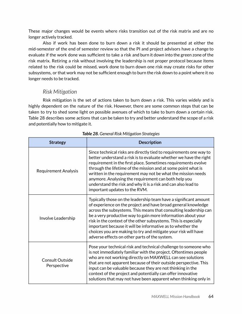
These major changes would be events where risks transition out of the risk matrix and are no longer actively tracked.
Also if work has been done to burn down a risk it should be presented at either the mid-semester of the end of semester review so that the PI and project advisors have a change to evaluate if the work done was sufficient to take a risk and burn it down into the green zone of the risk matrix. Retiring a risk without involving the leadership is not proper protocol because items related to the risk could be missed, work done to burn down one risk may create risks for other subsystems, or that work may not be sufficient enough to burn the risk down to a point where it no longer needs to be tracked.
Risk Mitigation Risk mitigation is the set of actions taken to burn down a risk. This varies widely and is
highly dependent on the nature of the risk. However, there are some common steps that can be taken to try to shed some light on possible avenues of which to take to burn down a certain risk. Table 28 describes some actions that can be taken to try and better understand the scope of a risk and potentially how to mitigate it.
Table 28. General Risk Mitigation Strategies
Strategy Description
Requirement Analysis
Since technical risks are directly tied to requirements one way to better understand a risk is to evaluate whether we have the right requirement in the first place. Sometimes requirements evolve through the lifetime of the mission and at some point what is written in the requirement may not be what the mission needs anymore. Analysing the requirement can both help you understand the risk and why it is a risk and can also lead to important updates to the RVM.
Involve Leadership
Typically those on the leadership team have a significant amount of experience on the project and have broad general knowledge across the subsystems. This means that consulting leadership can be a very productive way to gain more information about your risk in the context of the other subsystems. This is especially important because it will be informative as to whether the choices you are making to try and mitigate your risk will have adverse effects on other parts of the system.
Consult Outside Perspective
Pose your technical risk and technical challenge to someone who is not immediately familiar with the project. Oftentimes people who are not working directly on MAXWELL can see solutions that are not apparent because of their outside perspective. This input can be valuable because they are not thinking in the context of the project and potentially can offer innovative solutions that may not have been apparent when thinking only in
MAXWELL Mission Handbook 64

the context of the project.
Technology Demonstration Plan The Technology Demonstration Plan is the approach that the MAXWELL mission will take
to accomplish its mission objectives. For MO1-4 there are a lot of logistics that need to be accounted for in order to succeed. There are two main approaches to accomplishing these MOs.
The first option is to make everything automated onboard the satellite. This is a difficult task and requires a lot of testing and capability to be added to the flight system. While this is possible, there may be schedule constraints and personnel constraints that might make this option less feasible. The second option is to have a simpler flight system and a human in the loop when performing the technology demonstrations for MO1-4. The MAXWELL Ground Station Experiment Plan is a much more detailed document that explains the highly automated and the human in the loop options for accomplishing MO1-4. This document also includes the automated and human in the loop demonstration plans for the T-DaHGR in MO6.
To accomplish MO-5 the concept of operations is simpler because the satellite does not need to interface with multiple ground stations and perform complex slew maneuvers over the ground stations. Since the CSAC experiment happens passively without the need for active control, the satellite can essentially enter a safe, sunpointing operating mode while the experiment is active. TT&C communications can occur while the satellite is in any orientation so spending the five days required for the CSAC experiment to be completed in a sunpointing configuration is ideal because it maximizes power and minimizes spacecraft risk.
A slightly more involved technology demonstration plan for the CSAC experiment and MO5 involves balancing power generation with optimal GPS antenna coverage. Since the CSAC experiment relies on continuous GPS coverage then better data can be collected if the spacecraft seeks to maximize GPS antenna coverage while balancing that need with the power required to maintain a power positive state on the spacecraft during the experiment.
Launch Opportunities MAXWELL is unique in the fact that the majority of the project is completed without
certainty on the exact launch date, launch vehicle, and launch orbit chosen. Instead an envelope is chosen based on the analysis of what is needed to accomplish the mission objectives. To get a launch date and a ride on a launch vehicle MAXWELL presents each year after Flight Selection Review at the AFRL, Air Force, and Department of Defense (DoD) Space Experiments Review Board (SERB).
Presenting at the SERB is a greatly important responsibility for the student leadership on MAXWELL. The SERB is the entity that prioritizes space experiments and works to purchase launch vehicles and assign secondary payload slots to space experiments within the DoD portfolio. Since MAXWELL is funded through the UNP program the SERB is the primary entity which
MAXWELL Mission Handbook 65

manifests the MAXWELL mission as a secondary payload on a DoD launch vehicle when the mission is ready to fly.
The SERB, the UNP office, and the MAXWELL team cooperate such that an appropriate secondary payload slot is selected for flight. MAXWELL presents at all three SERB presentations each year as a secondary payload. Table 29 details the desired orbit envelope for the MAXWELL mission. At each SERB presentation, MAXWELL is prioritized by the review board amongst the other missions. Early presentations to the SERB serve to inform the SERB about the mission and the latter presentations are geared toward making sure the SERB is aware that the mission is nearing flight testing and eventually ready for flight.
Once MAXWELL is ready for flight the SERB begins to offer launch slots to secondary payloads by running down its priority list. The SERB contacts the UNP program office with potential launch opportunities and when an opportunity that fits the MAXWELL mission profile is available, then the UNP office consults with the MAXWELL team to determine if that official launch and delivery date works for the MAXWELL program. If everything lines up then late in Phase B or early Phase C a launch date is selected and the MAXWELL program is on the clock to deliver a flight ready satellite.
In February of 2020 the MAXWELL mission was also awarded a NASA CubeSat Launch Initiative (CSLI) selection by the NASA Launch Services Program. This is a prestigious selection that enables MAXWELL to also be launched via a NASA mission in addition to the DoD mission spots allocated by the DoD SERB. The NASA CSLI selection increases the number of potential launches that MAXWELL could be flown on.
Table 29. MAXWELL CubeSat Mission Parameters
MAXWELL CubeSat Mission Parameters
Mission Name
Mass Cube Size
Orbit Parameter
Desired Orbit
Acceptable Orbit Range
400km @ 51.6 degree
incl. Acceptable
Ready for Dispenser
Integration Date
Desired Mission
Life
MAXWELL 14kg 6U Altitude 550km 500km-600km No 2021-02-20 1yr
Inclination 55° >40°
Requirements Verification This section will ultimately be written when we start to do formal requirements
verification for the mission on EDU and Flight hardware. We will talk about the process for requirements verification, the range of tests that were completed for verification and potentially include details tracing requirements verification from the testing and results to the requirements at the satellite level.
MAXWELL Mission Handbook 66

Mission Validation This section will ultimately be written once the mission is nearing the end of its lifetime on
orbit. The goal of this section will be to reflect on the performance of the system in the context of the mission and determine if the system built was the right system. We will also look at some of the major lessons learned during operations in this section and from the process as a whole.
MAXWELL Mission Handbook 67