may 2 3 2qoo 1.edt 62958 of - digital library/67531/metadc741439/m2/1/high... · rpp-5963, rev. 0...
TRANSCRIPT

Pwa 1 Of 1 1.EDT 62958 ( MAY 2 3 2QOo ENGINEERING DATA TRANSMITTAL
(A) Item No.
2. To: (Receiving Organization) 1 3. Fmm: (Originating Organization)
(0) Re".
(C) Sheet
(6) DacumPnUDrawing No. NO. NO. (E) Title or Description OfData Transmitted Engineering Task Plan for the Intepritv
Dinibution 1 CH2MHill Equipment hgineering 5 rro;.iProg IDcpr.ll)i\ .. I 6. Design Aulhorll) Design AgcnLCog Engr
Approval Designator (F) E, S, Q, D or NIA :nee WHC-CMJ-5, Scc. 12.7)
DST System /Integrity Assessment 8. Originator Remarks: This EDT Transmits the data listed in Block 15 for review and approval preparatory to release.
I Cog. Engineer: DL Becker
Reason for Transmittal (0 Dispositim (H) & (I) I . Approval 4. Review 1. Approved 4. Reviewed ndcomment 2. Release 5. Post-Review 2. Approved wlcomment 5. Reviewed wlcomment 3. &formation 6. Dist. (Receipt Achow. Required) 3. Disapproved wlcomrnent 6 . Receipt achawlsdgsd
11. Receiver Remarks: 1 IA. Design Baseline Document? [I Yes [XI No
(G) (H) RPW" Dirp.
5. DATA TRANSMITTED I I I I
(GI (e) (1)Name (K) Sipalure &)Dale (M)MSW Rearan Disp. (I) Name 00 Signahre @)Date (WMSIN
Design Authority : NIA
Design Agent : N/A
-0d Design Authority1 Date
1 IMP-5963
, . Clrl No
[I Approved [I Approved wiwrnments [I Disapproved wiwmments
- - - _ Assessment Examination of Double- Contained Receiver Tanks, Catch N/A I 0 I
I Tanks, and Ancillary Facilities I I I I
4. Related EDTNo.:
7. Purchase Order No.:
9. Equip./Component No.:
IO. SystemfBldg./Facility:
12. Major Assm. Dwg. No.:
13. PermiWPermit Application No.:
200 EasWes t Area
14. Required Response Date A ASAP - 03
Approval Designator
E
Origi-
farTrans- Dispo- Dispo- sition sition
Reason nator Receiver
' I l l
Cog. Mgr. DB Smet
8.
lriginator
I Y
f - f ? + 3 p C EA Fredenbuq Authorized Representative Date Far Receiving Organization
20. I 21. DOEAPPROVALlifreauired\
Cognizant Manager I BD-7400-172-2 (10/97)
~~
BD-7400-172-1
BD-7400.172-1
. __

Engineering Task Plan for the Integrity Assessment Examination of Double-Contained Receiver Tanks, Catch Tanks, and Ancillary Facilities D. L. Becker Numatec Hanford Corporation, Richland, WA 99352 U.S. Department of Energy Contract
EDT: 629587 Org Code COA B&R Cod
KEY WORDS: Double-Contained Receiver Tank (DCRT), Double-Shell Tank (DST), catch tank, ancillary facility, integrity examination, leak test, leak check, in-tank video inspection, closed circuit television (CCTV), corrosion assessment, pump pit inspection, annulus inspection, vault inspection, integrity assessment report.
REFERENCE DOCUMENT: WAC-173-303-640
ABSTRACT: This Engineering Task Plan (ETP) presents the integrity assessment examination of three DCRTs, seven catch tanks, and two ancillary facilities located in the 200 East and West Areas of the Hanford Site. The integrity assessment examinations, as described in this ETP, will provide the necessary information to enable the independently qualified registered professional engineer (IQRF'E) to assess the
TRADEMARK DISCLAIMER. Reference herein to any specific commercial product, process, or service by trade name, trademark, manufacturer, or otherwise, does not necessarily constitute or imply its endorsement, recommendation, or favoring by the United States Government or any agency thereof or its contractors or subcontractors.
Printed in the United States of America. To obtain copies of this document, contact: Document Control Services, P.O. Box 950, Mailstop H6-08, Richland WA 99352, Phone (509) 372-2420; Fax (509) 376-4989.
c
Approved for Public Release
A-6400-073 (01/97) GEF321

condition and integrity of these facilities. The plan is consistent with the Double-Shell Tank Waste Transfer Facilities Integrity Assessment Plan (Hundal 1998).
TRADEMARK DISCLAIMER. Reference herein to any specific commercial product, process, or service by trade name, trademark, manufacturer, or otherwise, does not necessarily constitute or imply its endorsement, recommendation, or favoring by the United States Government or any agency thereof or its contractors or subcontractors.
Printed in the United States of America. To obtain copies of this document, contact: Document Control Services, P.O. Box 950, Mailstop H6-08, Richland WA 99352, Phone (509) 372-2420; Fax (509) 376-4989.
Release Approval Date Release Stamp
Approved for Public Release
A-6400-073 (01/97) GEF321

RPP-5963. Rev. 0
ENGINEERING TASK PLAN FOR THE INTEGRITY ASSESSMENT
CONTAINED RECEIVER TANKS, CATCH TANKS, AND ANCILLARY FACILITIES
EXAMINATION OF DOUBLE-
Prepared by: COGEMA Engineering Corporation P.O. Box 840 Richland, Washington 99352
Author: Earl B. Schwenk
Prepared for and under the direction o f CH2M HILL Hanford Group, Inc. Richland, Washington 99352 Contract Number 4848. Release Number 91
Date Published: May 2000
I

RPP-5963. Rev. 0
COCEMA E N G I N E E R l N G C O R P .
ENGINEERING TASK PLAN FOR THE INTEGRITY ASSESSMENT EXAMINATION
OF
RECEIVER TANKS, CATCH TANKS,
AND ANCILLARY FACILITIES
DOUBLE-CONTAINED
Prepared By: Date: -5 13/00 E. B. Schwenk, COGEMA Engineering Corporation
- Reviewed By: r Date: 7-\- 00 -
T. S. Hundal, Washingion State Registered Professional Engineer COGEMA Engineering Corporation
Approved By: Date: K. V. Scott, Manager COGEMA Engineering Corporation
.. 11
- . __ __

RPP-5963, Rev. 0
LIST OF ACRONYMS
ALARA CCTV CHG DCRT DOE DST ENRAF ETP FY HPT IAR IQRPE LC LED LLG MCCS PIC VITIS I1 UT USQ WAC WP
as low as reasonably achievable closed circuit television CH2M HILL Hanford Group, Inc. double-contained receiver tank U.S. Department of Energy double-shell tank tradename for liquid level gage engineering task plan fiscal year health physics technician integrity assessment report independent qualified registered professional engineer leak check light-emitting diode liquid level gauge motorized control camera system person in charge video in-tank inspection system ultrasonic testing unreviewed safety question Washington Administrative Code work package
... 111

RpP.5963. Rev . 0
TABLE OF CONTENTS ...
LIST OF ACRONYMS .............................................................................. 1 . 0 INTRODUCTION ........... ............................................................................................ 2 2.0 PURPOSE ............................................................................................................................... 3 3.0 SCOPE ............................................................................................................................... 3 4.0 DESCRIPTION OF FACILITIES ........................................................................................... 4
4.1 DOUBLE CONTAINED RECEIVER TANKS (DCRTS) ............................................... 4 4.2 CATCH TANKS ............................................................................................................... 5 4.3 ANCILLARY FACILITIES .............................................................................................. 7
5.0 INTEGRITY EXAMINATION ELEMENTS ......................................................................... 8 6.0 RESPONSIBILITIES ............................................................................................................ 10 7.0 PLAN FOR FIELD ACTIVITIES (FACILITY TESTLNSPECTION) ................................ 11 8.0 RECORDS ................................ .................................................... 12 9.0 INTEGRITY ASSESSMENT EXAMINATION REPORTING DETAILS ......................... 13 10.0 INTEGRITY ASSESSMENT EXAMINATION REPORTS .............................................. 14 11.0 REFERENCES .................................... .................................................... 15 APPENDIX A INSPECTION WORK SCO ............................................. A-1 APPENDIX B DESCRIPTION OF FACILITY, FACILITY SITE MAPS, DRAWINGS, AND
PHOTOGRAPHS ............ .............................................. B-l APPENDIX C OPERATIONS SCHEDULE .......................................................... C-1
......... 111
TABLE 1 TABLE 2a TABLE 2b TABLE 3 TABLE 4 TABLE A-1 TABLE A-2 TABLE A-3 TABLE A-4
LIST OF TABLES
DCRT Basic Information .......................................................... 5 Catch Tank Basic Examination Information-200 East Area .................... 6 Catch Tank Basic Information-200 West Area .................................. 7 Basic Examination Information on Ancillary Facilities ....................... 7 Assignment of Engineering Tasks., ............................................ 10 DCRT Integrity Examination Details ..................................................... A-2 Catch Tank Integrity Examination Details - 200 East Area ................... A-3 Catch Tank Integrity Examination Details - 200 West Area ................. A-4 Ancillary Facility Integrity Examination Details .................................... A-5
1
. .. ~

RPP-5963. Rev. 0
ENGINEERING TASK PLAN FOR THE INTEGFUTY ASSESSMENT EXAMINATION
CATCH TANKS, AND ANCILLARY FACILITIES OF DOUBLE-CONTAINED RECEIVER TANKS,
1.0 INTRODUCTION
The CH2M HILL Hanford Group, Inc. (CHG) operates a number of waste handling and storage facilities for the US. Department of Energy (DOE) at the Hanford site. These facilities are part of a network of interconnected, underground tanks, piping, and ancillary equipment that require periodic integrity assessment examination. The components addressed in this task plan are:
double-contained receiver tanks (DCRTs) catch tanks . ancillary facilities.
These facilities are contained within the double-shell tank (DST) waste storage systems, and are located in the 200 East and 200 West Areas of the Hanford Site.
Some of the DCRTs, catch tanks, and ancillary facilities have been in service for more than 50 years and essentially all contain dangerous waste constituents. Chapter 173-303-640(2) of the Washington (State) Administrative Code (WAC 1998) requires the performance of integrity assessments for each existing tank system that stores or treats dangerous waste. It further states that the owner and/or operator must obtain and keep on file at the facility, a written assessment reviewed and certified by an independent qualified registered professional engineer (IQRPE). Such integrity assessment reports (IARs) require the evaluation of the facility design as well as an evaluation of its physical condition, through an examination. This document only addresses the examination requirements and related details. The related design evaluations were completed in 1999.
Overall planning and implementation for the Integrity Assessment Program are described in the Double-Shell Tank Waste Transfer Fucilities Integrity Assessment Plan (Hundal 1998). Integrity assessment examinations were planned for fiscal year (FY) 1999. But, because of conflicts with higher priority tasks, most of the examinations were extended into FY 2000.
To obtain agreement on the remaining scope of examinations, including specific examination methods and facility access locations, working session meetings were held. These meetings included staff members from CHG (Planning/Scheduling, Cognizant Engineers, Tank Farm Operations, and Environmental Operations/Compliance), COGEMA Engineering personnel, and the IQRPE. The meetings resulted in the set of examinations presented in this task plan.

RPP-5963, Rev. 0
2.0 PURPOSE
This Engineering Task Plan (ETP) identifies the elements of integrity assessment examination scope and examination methods for three DCRTs, seven catch tanks, and two ancillary facilities (one Lift Station and one Waste Unloading Facility). The purpose of the examinations is to determine the present condition of dangerous waste storage tank systems and to determine their leak tightness and structural stability, as required by WAC 173-303-640(2). From these examinations, appropriate conclusions and recommendations will be documented and maintained on record at each facility. Some parts of the examination scope have already been conducted. For example, leak checks have been conducted on two DCRTs, seven catch tanks, and the lift station.
The facility examination, described in this ETP, will provide the necessary information to enable the IQRPE to certify the integrity assessment reports for the 12 facilities.
3.0 SCOPE
This ETP describes the performance requirements for integrity examinations that are to be conducted on:
three DCRTs (244-A, 244-BX, and 244-TX) seven catch tanks (AX-152, AZ-151, ER-311, EW-151, TX 302C. U-301B, and UX- 302A) two ancillary facilities - Lift Station A-350 - Waste Unloading Facility 204-AR.
The following plans are consistent with the requirements of the DST Wasre Transfer Facilities Integriry Assessment Plan (Hundal 1998) and are detailed in Appendix A, Tables A-1 through A-4.
The plans were made after considering the age and use of the facility components. All the facilities are old and have not been assessed since their initial service date. Each of the facility components that store waste will be leak tested and visually inspected internally.'. * Pump pits, pits, and/or vaults that are essentially the support components for each facility, and do not routinely hold waste will be visually examined but will not undergo a leak test.
The 2W-AR facility tank is an exception. Because of the difficulty of internal access, the tank will undergo I
ultrasonic wall thickness measurements.
'The AX-IS2 catch tank is another exception because of the difficulty of internal access, maintaining radiation levels as low as reasonably achievable (ALARA), and operational impacts.
3

RPP-5963, Rev. 0
4.0 DESCRIPTION OF FACILITIES
The three DCRTs, seven catch tanks, and two ancillary facilities to be examined are described below. Facility site maps, drawings, and photographs for each facility are shown in Appendix B.
4.1 DOUBLE CONTAINED RECEIVER TANKS (DCRTS)
There are three DCRTs to be examined in the 200 Areas: two in the 200 East Area and one in the 200 West Area. The DCRT systems function as small-capacity (about 19,000 to 31,000 gallons) short-term waste holdup stations during waste transfers. At the Hanford Site, the terms “lift station” (including saltwell station) and “DCRT” have often been used synonymously with the term “catch station.” The three units of each DCRT to be examined are:
receiver tank pump pit.
receiver tank vault (often termed annulus)
Receiver-Tank Vault. Each receiver tank is located inside a reinforced concrete vault to provide secondary (double) containment against contamination release to the environment. The vaults are designed to contain potential leakage of waste solutions from their primary vessels until the waste can be removed. The vaults are sized to contain 100% of the maximum allowed tank capacity. Each vault floor drains to a sump. The vault walls, floor, and sump are lined either with carbon steel or are painted with Amercoat’. The space between the steel tank and the concrete vault is termed the annulus.
The DCRT vault ceilings have penetrations that provide access for liquid-level detection devices, inspection equipment (such as video cameras), pumps and ventilation air supply and exhaust.
Receiver Tank. Each receiver tank is constructed of either carbon steel or stainless steel.
Pump Pit. In each DCRT, a pump pit is located above the receiver tank vault. The pit is separated from the annulus by a reinforced concrete floor supported by steel beams. Most penetrations into the primary tanks and into the annuli are through the pump pits. The pump pits contain pumps, valves, connectors, motors, and piping that are used for tank waste transfers and operations such as leak detection.
The three DCRTs, including basic examination information are shown in Table 1.
Manufactured by Protective Coating Division of Ameron, Brea, California
4

RPP-5963. Rev. 0
TABLE 1. DCRT BASIC INFORMATION4
DCRT (Location)
244-A (200 East)
244-BX (200 East)
244-TX (200 West)
CS = carbc
Structu
Primary Tank (size)
Type 347 SS (5116 in. tk. x I 4 ft. dia. x - 20 ft. high)
A 537 CI. ICs (3/8 in. tk. x 12 ft. dia. x - 39 ft. long)
A 537 CI. I CS (3/8 in. tk. x 12 ft. dia. x - 39 ft. long)
steel
Nominal Tank Volume Containment
[tank orientation]
Reinforced concrete with a CS liner (l/4in.)
- 17,800gal. [vertical]
Reinforced concrete with a coating of Amercoat
- 3 1 ,O(X) gal. [horizontal]
Reinforced concrete with a CS liner (1/4 in.)
- 3 1 ,OOO gal. [horizontal]
Components to be Examined
Pump pit, vault (annulus) and receiver tank
Pump pit and annulus completed Receiver tank.
Pump pit, annulus, and receiver tank
SS = stainless steel tk = thickness
4.2 CATCH TANKS
There are seven catch tanks in the 200 Areas: four in 200 East and three in the 200 West (for basic information, see Table 2a and 2b below). One tank in the 200 E Area (241-EW-15 1) is enclosed in a concrete pit. The other six tanks are direct buried with no access for examination of the outside of the tank. Two of the catch tanks are part of systems that each has a nominally different name. For example, 241-EW-151, is an air vent station that contains a catch tank, and 241-AX-152 is a diverter station that contains a catch tank.
These catch tanks are small-capacity underground tanks (nominal volumes from about 800 to 36,000 gallons). They provide interim containment for fluids associated with waste spillage, transfer-line flush water, or collection of rain and snowmelt water from other facilities or pipelines. The tanks are constructed from either carbon steel, stainless steel, concrete lined with metal, or concrete lined with gunite (essentially concrete without any aggregate).
4See document SD-WM-TI-352 for discussion of nominal tank volumes.

RPP-5963, Rev. 0
Table 2a. Catch Tank Basic Examination Information - 200 East Area4
Catch Tank
241-AX-152
241-AZ-151
Tank Structural Materials
rype 304L SS liner (I/X-in. tk.) with reinforced concrete backing
(6 ft. wide x 12 ft. deep x 22 ft. long)
A 569 CS ( IO-gage tk.) With reinforced concrete backing.
(6 ft. wide x 12 ft. deep x 24 ft. long.
Type 18-8-S-Cb SS@) (1/2 in. tk. x 9 ft. dia.
x 36 ft. long)
Type 309 SS (3/8 in. tk. x - 5 ft. dia
x - 7 ft. high)'''
Nominal Tank Volume [orien~ation]
-11,000gal. [horizontall
- 12,Ooo gel. lhorizontall
-17,670gal. [horizontal]
- 790 gal. [vertical]
(a) Essentially type 347 SS (b) 241-EW-I51 air vent station is located between the 200E and 200W areas. (c) The tank vault is constructed of reinforced concrete and is coated with Amercoat. CS = carbon steel SS = stainless steel tk = thickness
4See document SD-WM-TI-352 for discussion of nominal tank volumes.
Components to be Examined
Pump pit and diverter pit.
Pump pit, diverter pit, and catch tank
Catch tank and pump pit.
Catch tank, annulus, and nozzle pit

RPP-5963, Rev. 0
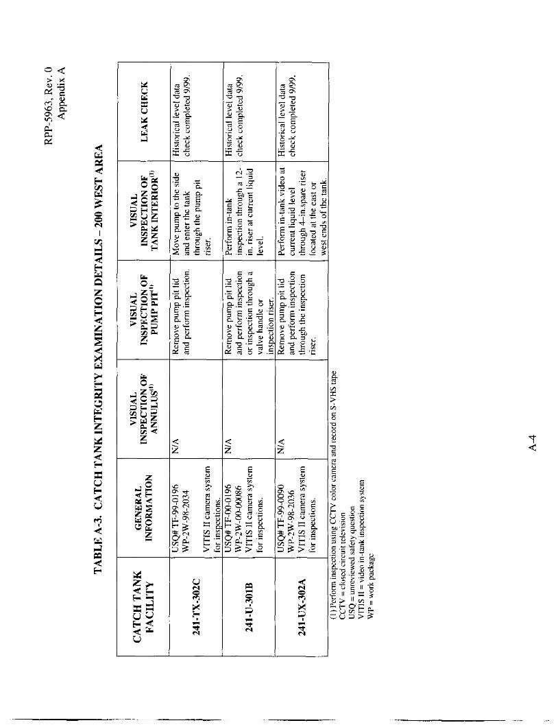
Table 2b. Catch Tank Basic Examination Information - 200 West Area4
Catch Tank
241-TX-302C
241-U-301B
241-UX-302A
2s =carbon steel
Tank Structural Materials
A 285-46 Gr. B CS (9/l6 in. tk. x 9 ft. dia. x 39 ft. long)
Gunite liner (3/4-in. tk.) with prestressed concrete backing
(21 ft. dia. x 21 ft. high)
A 285-46 Gr. B CS (9/16-in. tk x 9 ft. dia. x 39 ft. long)
Nominal Tank Volume
[Orientation]
- 17,670 gal [horizontal]
- 36,430 gal. [vertical]
- 18.60 gal. [horizontal]
Components to be Examined
Catch tank and pump pit
Catch tank and pump pit
Catch tank and pump pit
Gunite = cement-sand combination (no aggregate) tk = thickness
4.3 ANCILLARY FACILITIES
The ancillary facilities include one lift station and one waste unloading facility, each of which contains a catch tank in a concrete tank pit. Basic examination information regarding the two ancillary facilities is shown in Table 3.
TABLE 3. BASIC EXAMINATION INFORMATION ON ANCILLARY FACILITIES4
Ancillary Facility (location)
Lift Station 241-A-350
(200 E)
Waste Unloading Facility 204-AR (200 E)
SS = stainless steel
STRUCTUI
Primary Tank (wall thickness)
Type 309 SS (3/8-in. tk. x
4.5.ft. dia. x 7 ft. high)
Type 304L SS (1/4 in. tk. x 5.5
ft. dia x 8.5 ft. high)
LL MATERIALS
Secondary Containment (wall thickness)
Corrugated galvanized steel caisson backed by
grout ( I2 gauge)
Reinforced concrete lined with 'A in. tk. SS
:k = thickness
Nomina I Tank
Volume [orientation]
-790 gal. [vertical]
1,500 gal [vertical]
Components To Be Examined
Pump pit, catch tank pit (caisson), and catch tank
Catch tank and Catch tank pit

RPP-5963, Rev. 0
5.0 INTEGRITY EXAMINATION ELEMENTS
The requirements for assessment of an existing tank system’s integrity are provided in WAC 173-303-640(2) (WAC 1998). Section WAC 173-303-640(2)(~) states as follows.
This assessment must determine that the tank system is adequately designed and has sufficient structural strength to ensure that it will not collapse, rupture, or fail. At a minimum, this assessment must consider the following: (i) Design standard(s), if available, according to which the tank system was constructed; (ii) Dangerous characteristics of the waste(s) that have been and will be handled; (iii) Existing corrosion protection measures; (iv) Documented age of the tank system, if available (otherwise, an estimate ofthe age);
(v) Results of a leak test, internal inspection, or other tank system integrity examination and
such that: (A) For nonenterable underground tanks, the assessment must include a leak test that
is capable of taking into account the effects of temperature variations. tank end deflection. vapor pockets, and high water table effects; and
(B) For other than nonenterable underground tanks and for ancillary equipment, this assessment must include either a leak test, us described above, or other integrity examination, that is certified by an independent, qualified, registered professional engineer, in accordance with WAC 173-303-810 (13)(a). that addresses cracks. leaks. corrosion, and erosion.
Items (i) through (iv) require an assessment of design-related elements, whereas item (v) requires an assessment of examination-related elements. The approach that has been applied for compliance with the design-related elements is documented in Double-Shell Tank Waste Transfer Facilities integrity Assessment Plan (Hundal 1998). The approach for compliance with the examination-related elements is discussed below.
The WAC 173-303-640 (2)(c) requires, for “nonenterable” underground waste tanks “a leak test that is capable of taking into account the effects of temperature variations, tank end deflection, vapor pockets, and high water table effects.” For “other than nonenterable” underground tanks, this regulation requires either a leak test or other means of integrity examination, as an alternative to a leak test, “that is certified by an independent, qualified, registered professional engineer, in accordance with WAC 173-303-810 (13)(a), that addresses cracks, leaks, corrosion, and erosion.” Because of radiological hazards, the DCRTs, catch tanks, and miscellaneous tanks that are the subject of this engineering task plan, are not enterable by humans, but are enterable by means of remotely operated equipment. It is not clear which definition is intended in the WAC regulations in use of the terms “nonenterable” and “other than nonenterable”. Therefore, because of the radiological hazards, the waste tanks identified for evaluation in this engineering task plan are considered to be “nonenterable”, due to the need to comply with 10 CFR 835,29 CFR 1910 and 29 CFR 1926. Removal ofwaste and decontamination of the tanks is not feasible at this time.
8

RPP-5963, Rev. 0
Per the above stated requirements of WAC 173-303-640 (2)(c), the minimum requirement for tank examination of any tank (nonenterable or other than nonenterable) is satisfied by conducting a leak test. Acceptance criteria will be established by the independent qualified professional engineer for each leak test. Historical liquid level monitoring data and data from leak detection instruments may be documented and used for assessment of leak tightness and compliance with the leak test requirement. To minimize waste generation, and where historical liquid level data cannot be used, leak tests will in general be performed with liquid from normal process operations, i.e., without addition of liquid solely for the purpose of conducting the required leak test. The only exceptions to this are 241-AX-152, which is currently empty and not expected to be filled to sufficient depth for a leak test, through normal process operations, in the foreseeable future, and 204-AR which may require the addition of a small quantity of raw water.
In addition to meeting the minimum requirements for tank examination by leak testing, additional examinations will be performed utilizing CCTV and video recording equipment, where practical, to address cracks, leaks, corrosion and erosion. (Deployment of remotely operated CCTV for examination of the interior of tanks, or for examination of the exterior of tanks, is certainly not as effective as would be visual examination by a trained professional, where tank conditions permit human access). Deployment of remotely operated CCTV for examination of tank interiors, exteriors, pump pits, and vaults may provide additional useful information for the purpose of assessing overall condition of a tank system, including identification of large cracks, coating failures, and structural deterioration. Given the age of many of these tanks, and the potential environmental, cost, and schedule impacts of tank failure, examination by CCTV, where practical, is considered prudent, even though not required by the regulations. The additional information obtained through deployment of CCTV will allow for a more inclusive assessment of the tank system and more appropriate recommendations for future operation and use. For some tanks, gaining such access for CCTV examination would be particularly difficult, since tanks were in general not designed or constructed to permit human access. For such tanks, the value of the additional information to be gained may not be sufficient to justify cost, risk of worker exposure to radiation and chemical hazards, and potential impacts to operations. Because of these factors, internal CCTV examination of tanks 241-AX-152 and 204-AR was ruled out. However, the exterior of 204-AR is accessible for remote ultrasonic examination, which will be conducted to supplement the tank leak test. The facilities’ planned examination work scope and operations schedule is presented in Appendix A and Appendix C respectively.
Ecology’s guidance (Ecology 1994) for integrity assessment of tank systems addresses secondary containment, as well as primary tanks. This guidance suggests visual inspection alone is an adequate method of integrity examination for secondary containment. Thus, where vaults are provided for the tanks covered by this engineering task plan, the required visual examination will be accomplished by CCTV.
9

RPP-5963. Rev. 0
ENGINEERING TASKS
6.0 RESPONSIBILITIES
Table 4 identifies the engineering tasks, by responsible individual, that need to be performed in order to complete the integrity assessment examination. Nothing in this ETP prevents a person from assuming more than one role for a task (such as the field engineer and lead engineer being the same person), or two persons dividing up the responsibilities of one role.
RESPONSIBLE COMPANY
RESPONSIBLE INDIVIDUAL
Cognizant Engineer/Cognizant Manager
Facility ManagerRIC
Planner
Field Engineer
Lead Engineer
IQRPE
ETP = engineering task plai
Table 4. Assignment of Engineering Tasks
1. Coordinate and integrate scope of tank examination
2. Approve schedules 3. Manage overall project 4. Approve final reports 1. Provide personnel to support
scope of work (PIC, planners, camera crew, operators, and
CHG
CHG
1. Develop work package 2. Provide support to work package preparation 3 Help resolve tank farm interface issues
(radiological, permits, CHG
safety, etc.) 1. Prepare documentation supporting field activities I _ _ -
(ETPs, test plans, USQs, status, etc.) 2. Provide support to WP preparation. COGEMA Engineering
3. Provide support during facility visual inspection. I 1. Overall activitv leader
COGEMA Engineering 2. Ensure work is performed in accordance with this ETP
3. Prepare integrity assessment examination report I 1. Concur with examination scoDe
COGEMA Engineering 2. Examine and evaluate examination data and CCTV recordings.
3. Certify “fitness for use” .
HF’Ts = health physics technicians PIC =person in charge USQs = unreviewed safety questions CCTV = closed circuit television

RPP-5963, Rev. 0
7.0 PLAN FOR FIELD ACTIVITIES (FACILITY TESTDNSPECTION)
Individual work packages will be prepared for each tank inspection. The inspection will proceed according to the work instruction in the approved work package. In addition, the work instructions will point to the applicable guideline, procedure, or charter, as needed.
The facility manager will designate an operations PIC who has overall authority over the field performance of the inspections. This person will work closely with the lead engineer and the IQRPE to ensure that work proceeds according to the work instruction. Discovery of any leaks, structurally significant defects, gross deformation, or cracks will be documented. The inspection is expected to continue after discovery of any condition as just noted. Unless a problem is an emergency, or is of immediate safety concern, the PIC is expected to obtain input from the lead engineer before rendering decisions.
The specific items listed below address the major field activities. The responsible individual listed under each item has authority and responsibility for that aspect of the inspection work.
Work to be performed by tank farms personnel ( e g , removal of facility cover blocks and any other equipment blocking leak test/visual access that is feasible to be moved; establishing CCTV [or equivalent] access to the facility pitltanWannuluslsump, etc.), will have designated steps in the work package.
Responsible Individual: PIC
Write procedure for leak test and visual inspection.
Responsible Individual: Field Engineer
Setup, examination, and evaluation of visual examination equipment before deployment to the facility of interest.
Responsible Individual: PIC with support from Lead Engineer.
Setup and operation of visual examination equipment, including supplementary lights, at the facility of interest.
Responsible individual: PIC with support from Lead Engineer.
I 1

RPP-5963, Rev. 0
8.0 RECORDS
The following records will be prepared for this work, including reporting at the end of the facility test and inspections:
Procedure for leak tests
. Procedure for entering the facility annulus andor sump region (outside of tank), with a CCTV camera and lighting equipment, either through an inspection riser, manway, or spare riser
Procedure for removal (and replacement) of cover blocks (where necessary)
Procedure for entering the tank interior with a CCTV camera and lighting equipment, through a spare inspection risdmanway
Procedure for deployment and retrieval of CCTV equipment from a tank interior
.
CCTV examination procedure
. USQ screening or determination.
. CCTV report and video tapes containing, as a minimum, facility identification, date, time, location, reference elevation, depth, azimuth, pan, tilt, and position
An interim integrity assessment examination report that presents and explains the leak test and visual examination data from the facility examinations.
12

RPP-5963, Rev. 0
9.0 INTEGRITY ASSESSMENT EXAMINATION REPORTING DETAILS
A written report will provide the results of the facility integrity assessment examination proposed under the direction of the IQRPE and shall be prepared by a qualified person. The report shall be reviewed by the IQRPE to ensure that it contains the infomation needed to assess the facility as described in this ETP and in the integrity assessment plan (Hundal 1998). The assessment report should contain the following items:
. a site map of the facility, showing the location of the tank system within the overall facility
a sketch of the tank system with the location of the inspected items clearly indicated and cross-referenced in the results of the integrity assessment
an assessment of the existing tank system’s integrity according to WAC 173-303- 640(2)
results of the visual examination, including the leak testing or other methods used to assess tank system integrity
results of the secondary containment assessment examination (if applicable)
a statement by the IQRPE stating that the information collected is sufficient to support the assessment and is consistent with the integrity assessment plan
.
. conclusions and recommendations.

RPP-5963. Rev. 0
10.0 INTEGRITY ASSESSMENT EXAMINATION REPORTS
During interim stages of their preparation, the integrity assessment examination reports and supporting information and documentation will be provided to the IQRPE for review and comments. The format of these reports should be consistent with the DST Waste Transfer Facilities Integrify Assessmenr Plan (Hundal 1998) so that they can be incorporated into the final certified integrity assessment report.

RPP-5963, Rev. 0
11.0 REFERENCES
10 CFR 835, Occupational Radiation Protection, Code of Federal Regulation, 10 CFR 835, U. S. Department of Energy, Washington, DC.
29 CFR 1910, Occupational Safety and Health Standards. Code of Federal Regulation, 29 CFR 1910, U. S. Department of Labor, Occupational Safety and Health Administration, Washington, DC.
29 CFR 1926, Safety and Health Regulations for Construction, Code of Federal Regulation, 29 CFR 1926, U. S. Department of Labor, Occupational Safety and Health Administration, Washington, DC.
Ecology 1994, Guidance for Assessing and Certifiing Tank Systems that Store and Treat Dangerous Waste, Publication No. 94-1 14, Washington State Department of Ecology, Olympia, Washington, June 1994.
Hundal, T. S., 1998, Double-Shell Tank Waste Transfer Facilities Integrity Assessment Plan, HNF-3008, Rev. 0, COGEMA Engineering Corporation, Richland, Washington.
Jonas, A. L., September, 1988, Technical Basis for OSD-T-ISI-00015, SD-WM-TI-352 (See ECN April 1996), Rockwell Hanford Co. Richland, Washington.
WAC 1998, Dangerous Waste Regulations. WAC 173-303-640, Washington Administrative Code, Washington State Department of Ecology, Olympia, Washington.
15
.

d 2

VI .- - e C
E
L M 4J C El I
2 u n
1 I

I I
I I
L e 1 e
I I I I I
a
X U H 4 u
I I
1-r c 4 4 r. 2 z
I
P d

!i a cr:

RPP-5963, Rev. 0 Appendix B
APPENDIX B
DESCRIPTION OF FACILITY,
FACILITY SITE MAPS,
DRAWINGS,
AND
PHOTOGRAPHS
B- 1

RPP-5963, Rev. 0 Appendix B
DOUBLE-CONTAINED RECEIVER TANK 244-A
The 244-A DCRT/Lift Station is a reinforced concrete structure consisting primarily of three adjoining compartments that house different facility components:
receiver tank containment vault pump pit filter pit
Receiver tank containment vault. The receiver tank containment vault is located directly below the pump pit. It is cylindrical in plan view, with a 17-ft. inside diameter and 1-ft. thick concrete sidewalls. The vault floor slab is 1.5-ft. thick. Inside height of the vault is 22-ft. and 4-in. A collection sump is located 1 -ft. below the floor elevation, offset toward the northwest edge of the vault. One-quarter ( %-in. thick carbon steel plate lines the vault floor, sump and sidewalls up to the underside of the pump pit floor slab
Receiver tank. The tank is positioned inside the vault with the tank centerline offset 8-in. to the south of the vault centerline. The 244-A DCRT (originally designated TK- 387) is a cylindrical, 16,280-gal tank, constructed of welded type 347 stainless steel, 5/16-in.-thick, with hemispherical ends. The tank is installed in the 244-A vault with the cylinder axis vertical. Nominal dimensions are 14-ft diameter by 14 ft high (overall height is 21 ft, 1 in. measured from bottom of skirt and base ring to top of riser flange).
The tank was originally designed and fabricated in 1950 for the 276-U Solvent Handling Facility. This facility was used for makeup and treatment of organic solutions used in the 221-U Building (U-Plant operations). The 276-U mission began in 1952 and ended in 1957. It is unknown whether TK-387 was ever used at the original location. Tanks at 276-U were cleaned out and isolated in 1957. As part of Project B-103, TK-387 was relocated and modified for service at 244-A. Age, based on date of installation (in 244-A) is about 25 years (1975) while its physical age is as much as 50 years (1950).
Pump pit, The pump pit has inside dimensions of 13-ft. by 15-ft (plan) by 11-ft high and is located directly over the receiver vault. Coverage of the pump pit is provided by an 18-in.-thick concrete cover slab in three sections. The concrete floors and sidewalls of the pit are I-ft thick.
Filter Pit. The filter pit has inside dimensions of 1 1-ft by 13-ft (plan) by 5.5-ft high. The filter pit cover is constructed of 3/8-in. thick steel plate. Floors and sidewalls of the two upper compartments are all I ft thick. No examinations are planned for the filter pit.
B-2

i RPP-5963, Rev. 0
Appendix B
Figure B-I. SITE PLAN - 244-A Double-Contained Receiver Tank.
B-3
-.

RPP-5963, Rev. 0 Appendix B
. 20. mu. I’
3/E COVER PLATE
CONTAINMENT VAULT 1 7 s 1.0.
I I I I I I
--CCN CMERA REF. 0%. n-z-582o3 I
I b
I (W.)
6W-8. . ..
SECTION A-A
Figure B-2. 244-A Double Contained Receiver Tank
B-4


RPP-5963, Rev. 0 Appendix B
DOUBLE-CONTAINED RECEIVER TANK 244-BX
The 244-BX DCRT facility is an underground reinforced concrete structure consisting primarily of three main compartments that house different facility components. The three main compartments described below are:
receiver tank containment vault pump pit filter pit.
Receiver tank containment vault. The receiver tank containment vault is a rectangular reinforced concrete structure, approximately 20-ft. W x 48-ft. x 23-ft. H outside dimension with 2-ft. thick walls and a 3-ft. to 4-ft. thick bottom foundation slab. Amercoat No. 33 liner material (manufactured by Protective Coating Division of Ameron, Brea California) protectively coats the vault concrete. The foundation slab slopes down towards a trench on the east side of the vault, which slopes to a sump to collect liquids. The vault houses the primary receiver carbon steel (ASTM A 537 Class 1) horizontal tank.
Receiver tank. Receiver tank dimensions are: 3/8-in. thick by 12-ft. diameter cylindrical shell with %-in. thick dished heads on each end of the shell. Nominal capacity of the tank is 31,000 gallons with a maximum operating capacity limited to 24,800 gallons. Design corrosion allowance is 0.001 in./year, for each side of the tank, for 10 years of minimum intended useful life or 0.02 in. total. Secondary containment of the receiver tank is provided by the vault. Age of the tank is about 19 years (based on Construction Procurement Specification B-I80 initiation date of Sep. 1979, and an assumed completion date of about 1981).
Pump Pit. The pump pit is ZO-ft.(W) x 22-ft. (L) x 1 I-ft.-6-in.(H) with 18-in. thick walls. Its approximate 3-ft., thick floor slab is supported on steel beams and 4 1/2- inch metal decking. Location of the pump pit is directly above the vault on its south end. Transfer lines enter the pump pit walls at different elevations.
Filter Pit. Adjoining the pump pit, also above the vault but on its north side, is the filter pit. It is a 13-ft. (W) x 20-ft. (L) x 1 l-ft.-6-in. (H) concrete structure with 18- in. thick walls and an approximate 3-ft., thick floor slab. No examinations are planned to be conducted in the filter pit.
B-6

RPP-5963, Rev. 0 Appendix B
'. --.._
i N4540,3.0
I, TANK 241 - t -E- - --
- NORTH
244-EX DCRT '\ (H-2-73784)
INSTRUMENT \ EUlWlNG I
- ---J-
3X-101
[i"FUJStl PIT
I \-EQUIPMENT
PAD I _- _/' k9
Figure B-4. SITE PLAN - 244-BX Double-Contained Receiver Tank.

-4 I $+ I”’
RPP-5963, Rev. 0 Appendix B
PLAN
/INST. PIT
SECTION A-A
M!xL OTHER FACILITY DETAILS ARE NOT SHOWN FOR CLARIM
Figure B-5. 244-BX Double-Contained Receiver Tank.
B-8

......... ~. . . . . . . . . . . . . . . . . . . . . . . . . . .........

RPP-5963, Rev. 0 Appendix B
DOUBLE-CONTAINED RECEIVER TANK 244-TX
The 244-BX DCRT facility is an underground reinforced concrete structure consisting primarily of three main compartments that house different facility components. The three main compartments described below are:
The pump pit and, The filter pit.
The receiver tank containment vault
Receiver tank containment vault. The receiver tank containment vault is a rectangular reinforced concrete structure, approximately 20-ft. W x 48-ft. x 23-ft. H outside dimension with 2-ft. thick walls and a 3-ft. to 4-ft. thick bottom foundation slab. Amercoat No. 33 liner material (manufactured by Protective Coating Division of Ameron, Brea California) protectively coats the vault concrete. The foundation slab slopes down towards a trench on the east side of the vault, which slopes to a sump to collect liquids. Leak detection devices and a pump (when required) are housed in the sump. The vault houses the primary receiver carbon steel (ASTM A 537 Class 1) horizontal tank.
Receiver tank. Receiver tank dimensions are: 3/8in. thick by 12-ft. diameter cylindrical shell with %-in. thick dished heads on each end of the shell. Nominal capacity of the tank is 3 1,000 gallons with a maximum operating capacity limited to 24,800 gallons. Design corrosion allowance is 0.001 in./year, for each side of the tank, for 10 years of minimum intended useful life or 0.02 in. total. Secondary containment of the receiver tank is provided by the vault. Age of the tank is about 19 years (based on Construction Procurement Specification B- 180 initiation date of Sep. 1979, and an assumed completion date of about 1981).
Pump Pit. The pump pit is 2O-ft.(W) x 22-ft. (L) x 1 I-ft.-6-in.(H) with 18-in. thick walls. Its approximate 3-ft., thick floor slab is supported on steel beams and 4 1/2- inch metal decking. Location of the pump pit is directly above the vault on its south end. Transfer lines enter the pump pit walls at different elevations.
Filter Pit. Adjoining the pump pit, also above the vault but on its north side, is the filter pit. It is a 13-ft. (W) x 20-ft. (L) x 1 l-ft.-6-in. (H) concrete structure with 18- in. thick walls and an approximate 3-ft., thick floor slab. No examinations are planned for the filter pit.
B-IO

RPP-5963, Rev. 0 Appendix B
NORTH
E
Figure 8-7. SITE PLAN - 244-TX Double-Contained Receiver Tank
B-1 I

RPP-5963, Rev. 0 Appendix 8
U N
ANST. PIT
THlCU UNER PL
SECTION A-A
&?% FACILITI O€rAlLS *RE NOT SHOWN FOR ctmm
Figure B-8. 244-TX Double-Contained Receiver Tank.
B-12

. . . . . . . . . . . . . . . . . . . . . . . . . . . . .

RPP-5963, Rev. 0 Appendix B
CATCH TANK 241-AX-152
The 241-AX-152 Diverter Station catch tank is located between the 241-AY double- shell tank farm and the 241-AX single-shell tank farm, in the 200 East Area. The diverter station consists of a pump pit, a cell (or diverter pit) containing two diverter assemblies, and a vault, with a liner, constituting the catch tank. The pump pit and diverter cell are situated above the catch tank vault. A 24-in. dia. riser extends up from the catch tank vault into the pump pit, but not through the pit cover blocks.
Catch tank (vault). The vault is a rectangular vault made of reinforced concrete and fully lined (floor, walls and ceiling) with 1/8-in. thick type 304L stainless steel sheet welded at all joints). Vault (tank) dimensions are 22-ft.-2-in. long by 6-ft wide by 11- ft.-S-in. deep. Depth, to the inside surface of the tank bottom is believed to be 27.2-ft. Age, based on date of installation (1962), is 38 years.
Pump pit. The pump pit, constructed of reinforced concrete, houses a submersible pump, jumpers, and other ancillary equipment and resides over the catch tankhault. Pump pit dimensions are 6 ft. (L) x 6 ft (W) x 13 ft. - 7 in. (D). The pit is coated with a sealant to mitigate seepage through its walls and floor.
Diverter pit. The diverter pit, constructed of reinforced concrete, is adjacent to the pump pit and has dimensions 14 ft. - 8 in. (L) x 6 ft. (W) x 16 ft. (D). It contains two stainless steel vessels or assemblies (Operator A and Operator B), each with a capacity of 50 gallons. A movable spout is located at the bottom of each vessel and is used to direct waste out of its vessel and into a number of exit pipe nozzles. The pit floor is lined with 1/8 in. thick stainless steel sheet.

RPP-5963, Rev. 0 Appendix B
\
U / K -.- I I -.-
Figure B-10 SITE PLAN - 241-AX-I52 Catch Tank.
B-15

RPP-5963, Rev. 0 Appendix B
,
Figure B-11. 241-AX-152 Catch Tank

. . . . . . . . . . . . . . . . . . . . . . . . . . . . . . . . . . . . . . . . . . . . . . . . .

RPP-5963, Rev. 0 Appendix B
CATCH TANK 241-AZ-151
The 241-AZ-151 catch tank is located just west of sluice transfer box AZ-152 and consists of a pump pit and a catch tanwvault. The pump pit is square in cross-section and sits atop one end of the catch tanwvault.
Catch tank (vault). The vault is rectangular, made of reinforced concrete. All inside surfaces of the catch tank are lined with ASTM A 569 steel sheets of 10 gage (about 0.135 in.) thickness. The liner sheets were welded with a tungsten-inert gas process per Hanford welding specification, but were not thermally stress-relieved. Thus, weld-induced residual stresses remain high. The sheets are sealed at all joints, edges, and corners. Dimensions of the tank are 24 ft. (L) x 6 ft. (W) x 11 ft. (D). Catch tank pipe penetrations are welded to the liner. Tank maximum and administratively controlled volumes are 11,900 and 9,520 gallons, respectively. Age, based on date of installation (1973) is 27 years. The bottom of the tank is approximately 30 ft. below ground level.
Pump pit. The pump pit inside dimensions are 6 ft. (L) x 6 ft. (W) x 10 ft.-9 inches (D). The inside surfaces of the pit area coated with a protective coating. Housed in the pit are a submersible pump, jumpers, and other ancillary equipment.
B-18

RPP-5963, Rev. 0 Appendix B
Figure B-13. SITE PLAN - 241-AZ-151 Catch Tank.
B-19

RPP-5963, Rev. 0 Appendix B
PLAN VIEW
"TW
CaHJknK
1/0' THK UHER C
SOP EL 659.84
Figure B-14. 241-AZ-151 Catch Tank.
B-20
~ . - __I._


RPP-5963, Rev. 0 Appendix B
CATCH TANK 241-ER-311
Location of the catch tank is south and slightly west of B Plant in the 200 East Area of the Hanford Site. It consists of a pump pit at grade level with a 12-in. diameter riser connecting to the direct-buried tank.
Catch tank. ER-311 catch tank is a horizontal cylindrical vessel, 9 ft. outside diameter and 36 ft long, with dished ends. The tank is buried about 22 ft. (to the centerline of the tank) below grade.
The first ER-3 11 catch tank was replaced in 1954. The replacement tank was fabricated in 1943 from 1/2-in. thick 18-8 S Cb (essentially type 347) stainless steel plate and it had been used from 1944 to 1954. as tank 21 1-B-108, apparently above ground. The nature of the liquid stored in it during the IO-year period was not determined. The tank was modified in 1980 under Project B-231.
Pump pit. Modifications in 1980 resulted in ER-3 11 being provided with underground pump-out capability and addition of a pump pit. The pit contains a locally controlled submersible pump and pump-out jumper. The pit is approximately 7 feet square and 7 ft. - 4 in. (D).
B-22
._. . -_ _.

RPP-5963, Rev. 0 Appendix B
Figure B-16. SITE PLAN - 241-ER-311 Catch Tank.
B-23
- .

RPP-5963, Rev. 0 Appendix B
241-ER-151 DIVERSION aox
Figure B-17. 241-ER-311 Catch Tank.
B-24

.... . . . . . . . . . . . . . . . . . . . . . . . . . .

RPP-5963, Rev. 0 Appendix B
AIR VENT STATION 241-EW-151
The 241-EW-151 air vent station is located between the 200 West and East Areas of the Hanford Site and is approximately 1,500 feet south of the Eastmest Fire station. It is part of the EW-15 I diversion box that consists of a nozzle pit atop the catch tank pit (or vault), the catch tank, and a stairway to an access pit. The access pit provides a door for access to ports the inside of the catch tank pit.
Catch tank pit. Inside dimensions of the catch tank pit are 8 ft. - 6 in. (L) x 8 ft. (W) x 8 ft.- 4 in. (H). Its walls are I-ft. thick. The pit was constructed of reinforced concrete and is apparently coated with white Amercoat # 55.
Catch tank. Dimensions of the catch tank are 4 ft. - 6 in. outside diameter and 6 ft.-l1 in. high and it is mounted vertically. In addition, the tank has a stainless steel cooling jacket (apparently made of type 18-8 Cb SS). The jacket was welded in place after the tank was heat treated. Prior to the tank being installed in 195 1-1952 in the ER-3 11 facility, it had been used as tank 221-U-217 for an estimated 8 years. U Plant was intended to be used for the BiP04 fuels-separation process where waste sludge was to be dissolved in nitric acid. The plant was never used for this process as B Plant and T Plant had sufficient capacity. Because the tank was apparently removed (1951-1952) before the plant was eventually used for uranium recovery operations (1952 to 1958) the tank may not have seen any severe service (this has not been confirmed). Based on the U Plant construction start date of March 1943, the tank’s age is assumed to be 56 years.
Nozzle pit. The nozzle pit was constructed of reinforced concrete and sits atop the catch tank pit. Its inside dimensions are 8 ft. x 6 ft. x 5 ft.- 8 in. and it was coated with white Amercoat # 55. The floor drain to the catch tank pit is reported to be plugged.
B-26
-

RPP-5963, Rev. 0 Appendix B
1
Figure B-19. SITE PLAN - 241-EW-151 Catch Tank.
B-27

RPP-5963, Rev. 0 Appendix B
9.10-
,
CATCHTANK
11'6'. I l- PLAN
i
1
f 1- 'i t-r-
1
CATCHTANK PIT
L w
P
c
1
LJJAS036 SECTION A-A
Figure 8-20, 241-EW-151 Catch Tank.
B-28
-

... . . . . . . . . . . . . . . .

RPP-5963, Rev. 0 Appendix B
CATCH TANK 241-TX-302C
The 241-TX-302C catch tank is located east of T Plant (200 West Area), near the middle of the building. The facility consists of a direct buried carbon steel tank with a pump pit located above the center of the tank.
Catch tank. The tank is a horizontal cylindrical vessel 8-ft., 10 and 7/8-in., inside diameter by 39-ft., 4 and 1/4-in. long. Material of construction was welded ASTM A- 285-46 Grade B carbon steel, 9/16-in. thick. The tank was thermally stress-relieved following welding. Exterior and interior surfaces were cleaned and sand blasted. The exterior surface was coated with coal tar enamel and the interior surface was left untreated. Depth to the inside surface of the tank bottom is believed to be about 32-ft. Age, based on date of installation (1947), is 53 years.
Pump pit. The pump pit, including a 12 in. diameter ASTM A 53 carbon steel pipe riser that connects to the center of the tank, was added to the facility in 1984. The pit is a 5-ft. inside diameter galvanized, corrugated metal pipe that is 4-ft.-6-in. deep and sets on a concrete floor. The riser descends approximately 23-ft. from the pump pit to the tank. Age of the pump pit is about 16 years.

RPP-5963, Rev. 0 Appendix B
Figure 8-22, SITE PLAN - 241-TX-302C Catch Tank.
B-3 1

RPP-5963, Rev. 0 Appendix B
DIVERSION BOX
ELEVATION
Figure B-23. 241-TX-302C Catch Tank.


RPP-5963, Rev. 0 Appendix B
CATCH TANK 241-U-301B
The 241 U-301B catch tank is located in the 200 West Area south of U-112 and east of U-252. The facility consists of a catch tank and a pump pit directly above the side of the tank.
Catch tank. The tank is made of prestressed concrete with an outside diameter of 20- ft., 10-in.and a wall thickness of 5 in. at the fill level tapering to 6-in. about 2 ft. above the radiused floor. The interior of the tank is coated with a 3/4-in. thick layer of Gunite (cement-sand with no aggregate). Overall height of the tank, to the top of the integrally cast dome, is 20-ft., 11 1/4-in. Capacity of the tank, is 36,000 gallons; it is approximately 6 to 7 ft. below grade. Age, based on date of installation (1944-1945), is 56 years.
Pump pit. The pump pit was made of 14 gage galvanized corrugated metal pipe and is 5 ft. in diameter and 5 ft. deep. It was installed in 1981 and has an age of 19 years.
B-34
-

RPP-5963, Rev. 0 Appendix B
Figure B-25. SITE PLAN - 241-U-3018 Catch Tank
B-35

RPP-5963, Rev. 0 Appendix B
Figure B-26. 241-U-301B Catch Tank
B-36

R
. . ~ . . ~ ........................ ~

RPP-5963, Rev. 0 Appendix B
CATCH TANK 241-UX-302A
The 241-UX-302A catch tank is located in the 200 West Area east of U Plant. It is a direct-buried horizontal cylindrical vessel made of carbon steel with a pump pit above the tank.
Catch tank. The tank is a horizontal cylindrical vessel 8-ft.-IO-in. ID by 39-ft., 4 1/4- in. long. The material of construction is 9/16-in.thick carbon steel plate per ASTM A- 285-46 Grade B. It was welded and stress-relieved in accordance with ASME Code Section VIII, paragraphs U-69 and U-76. Interior and exterior surfaces of the tank were cleaned of all mill scale and grease and were sand blasted. The tank’s exterior surface was coated with a coal tar enamel while the interior surface was left as is. Age, based on date of installation (1947), is 53 years.
Pump pit. The pump pit is a 5-ft. inside diameter, galvanized corrugated metal pipe which is 4-ft. - 6-in. deep and has a steel cover plate. A 12-in dia. schedule 40 riser, made of ASTM A 53 carbon steel, descends approximately 20-ft. from the pump pit to the tank.
B-38

Figure B-28. SITE MAP - 241-UX-302A Catch Tank.
B-39
__ _-
RPP-5963, Rev. 0 Appendix B

RPP-5963, Rev. 0 Appendix B
Figure B-29. 241-UX-302A Catch Tank.
B-40

KPP-
. . . . . . . .............. . . . . . . . . . . . . . . . . . . . . . . . . . . . . . . . . . . . . . . . . . . . . . . . . .

RPP-5963, Rev. 0 Appendix B
LIFT STATION 241-A-350
The lift station is located southeast of Single-Shell Tank 241-A-I06 in the 241-A SST Tank in the 200 East Area. The entire lift station structure consists of a pump pit located over a cylindrical-walled, corrugated steel caisson. The caisson, which is backed by a grout layer, sits atop a reinforced concrete floor that supports the catch tank.
Catch Tank Pit (Caisson). Directly below the pump pit is the cylindrical carbon steel-wall, grout-backed caisson; it is approximately 8-ft. in diameter and 17-ft. tall. Initially, the short, catch tank support feet sat directly on the one-ft. thick slab. Later, an additional concrete pour was made, with the tank in-place for improving the tank’s seismic response. The result was an additional 1-ft. thick layer of concrete that enveloped the support feet, apparently extending up several inches surrounding the bottom of the tank.
Catch Tank. The catch tank, weld-fabricated from 3/8-in. thick 25-12-S-Cb (approximately type 309 Cb) stainless steel), is positioned with its cylindrical axis in a vertical orientation. Its capacity is listed as 776 gallons. Dimensions of the tank are 4.5-ft. diameter and 6-ft. 1 1-in. high, and it has a sloped floor to minimize waste heel. In addition, the tank has an unused metal jacket (apparently for either water cooling or steam heating). It was designed about 1943, fabricated as early as 1944 (by the General Electric Company - Hanford Works for the Hot Semi-works), modified around 1950, and installed in the Lift Station in 1979. Prior service, if any, is unknown. Thus, its Lift Station service age is about 21 years (1979) while its physical age could he as much as 56 years (1943).
Pump Pit. The pump pit houses two pumps and an assortment of jumpers, connectors, and valves. Structurally, the pit is made of reinforced concrete with inside dimensions 9-ft. by 9-ft. by 11 ft. (L x W X H), and capped with a 20-in. thick cover block.
B-42
- .-

RPP-5963, Rev. 0 Appendix B
Figure B-31. SITE PLAN - 241-A-350 Lift Station.
B-43
-

RPP-5963, Rev. 0 Appendix B
Figure B-32. 241-A-350 Lift Station
B-44
- .. I -.

. . . . . . . . . . ...... . . . . . . . . . . . . . . . . . . ....

RPP-5963, Rev. 0 Appendix B
WASTE UNLOADING FACILITY 204-AR
The 204-AR Waste Unloading Facility is located south of the 244-AR Vault and west of the 241-AX Tank farm, in the 200 East Area. Completed in 1981, the facility is a two-story reinforced concrete structure approximately 64-ft. (L) x 49-ft. (W) x 25.5-ft (H). The primary facility to be examined, is the catch tank and catch tank pit which are located below-grade in the Rail Tank Car Unloading Canyon.
Any liquid waste spills, any decontamination solutions that drain to the floor, and any overflow or spills from the chemical makeup tanks, are collected in a stainless steel drain system. That system connects to the, below-grade stainless steel catch tank, which in turn, is contained in a stainless steel-lined pit containing a sump.
Catch Tank Pit. The floor and walls of the catch tank pit are constructed of reinforced concrete with inside dimensions, 7-ft. (L) x 6-ft. (W) x 14.5-ft. (H). Pit walls are 10- to 23-in. thick and are lined with a %-in. thick stainless steel plate up to a height of 10.5-ft. The 18-in. thick, concrete floor slab is sloped towards a 1-ft. x 1- ft x 8-in. deep sump, both of which are covered with the same stainless steel plate as are the sidewalls. A removable steel grating is fitted to the top of the pit to allow access to the catch tank and pit.
Catch Tank. The 204-AR catch tank (nominal volume of 1,500 gallons and a maximum operating capacity of 1,200 gallons) is cylindrical in shape with its axial centerline oriented vertically. The tank was fabricated from %-in. thick, welded, type 304L stainless steel; it is approximately 102-inches high by 66-inches in diameter. Location of the tank is beneath the floor of the unloading area. The catch tank is equipped with liquid-level instrumentation and drain/overflow lines. Age, based on date of installation (1981), is 19 years.
B-46

RPP-5963, Rev. 0 Appendix B
Figure B-34. SITE PLAN - Waste Unloading Facility.
B-41

Figure B-35. 204-AR Waste Unloading Facility Layout
RPP-5963, Rev. 0 Appendix B
B-48
.. _.

RPP-5963, Rev. 0 Appendix B
NORTH
kz
-- ma--\
I -
SEC-
Figure B-36. 204-AR Catch Tank.
B-49
. ..~ .~ I

. . . . . . . . . . . . . . . . . . . . . . . . . . . . . . . . . . . . . . . . . . . . . . . . . . . . . . . ....

RPP-5963, Rev. 0 Appendix C
APPENDIX C
OPERATIONS SCHEDULE
C- 1

3

c? 0 0 0

I


I
Tr
-
0
8 E


DISTRIBUTION SHEET
Bowen, K. M.
Bragg, D. A.
Brooks, R. L.
Brown, M. H.
Brown, T. M.
Page 1 of 2
Date 0 5 / 1 6 / 2 0 0 0
To
Project Titleiwork Order DISTRIBUTION
T4-08 X
55-05 X
57-90 X
T4-08 X
55-05 X
Engineering Task Plan for the Integrity Assessment Examination of
Cutforth, K. A. 55-12 X
Dillhoff. T. A. S 5 - 0 3
A-6000-135 (10197)
X

DISTRIBUTION SHEET
To Distribution
From Page 2 of 2
Engineering Task Plan for the Integrity Assessment Examination of Double - Contained reciever Tanks, Catch Tanks, and Ancillary Fac.
EDT No. 629855 5 8 7
ECNNo,
Name
Nicholson, R. S.
Niebuhr, D. P.
Parkman, D. B.
Attach'' EDTlECN Text
Only MSlN With All Text Only Appendix
55-05 X
55-03 X
55-13 X
Attach. Only
Rodriquez, R. S. 57-90 X
Scott, D. Jr.
Scott, K. V.
Shipler, C. E.
Smet, D. B.
55-07 X
H3-28 X
S2-25 X
R3-83 X
Sparks, D. L. 55-03 X
Sumsion, M. L.
Sutey, M. J.
Tardiff, G . R.
Wright, R. L.
Zilar. L. J.
55-03 X
S5-07 X
55-05 X
S5-03 X
S7-90 X