may 2018 + brick veneer - firth concrete · 3 disclaimer: please keep in mind when choosing firth...
TRANSCRIPT

+ Brick Veneer North ISLAND & South ISLAND
MAY 2018
Technical Guide
the brick and supporting construction referred to in this section is to follow the requirements of New Zealand Building Code Section E2/AS1. the following standards are referenced in that section: NZS 3604 timber Framed Buildings. NZS 4210 Masonry Construction: Materials and Workmanship. Additionally, the provisions of this section may be applied when used in conjunction with construction to NZS 4229, Concrete Masonry Buildings Not requiring Specific Design. If the scope of the proposed work is outside the limitations and requirements of the above then specific engineering design advice must be sought.
2
3
4
5
6
7
9
12
14
15
16
17
19
20
Firth’s Brick Range
Clear Sealing
Mortar
Joint Types
Laying Options & Specifications
Wall Ties / Zoning Guide
The Brick Cavity
Weather Step
Cavity Ventilation
Openings / Lintels
Flashings
Brick Veneer Construction - Building Heights
Brick Veneer Tolerance
3Disclaimer: Please keep in mind when choosing Firth concrete products, the beauty and appeal of concrete means there will be natural variation in colours. Colours may vary from batch to batch, and regionally as materials are natural and sourced locally. We advise viewing a current product sample before making your final decision, please contact your local Firth office and they will be happy to assist.
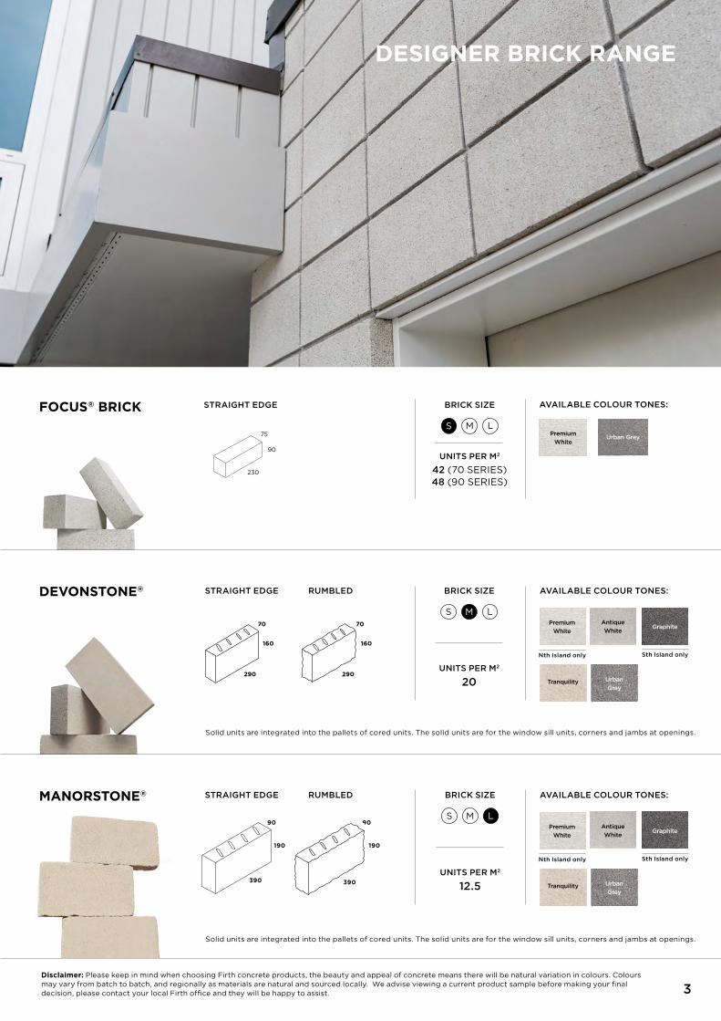
DEVONsTONE®
MaNOrsTONE®
FOCUs® BrICK
STRAIGHT EDGE
STRAIGHT EDGE
RUMBLED
RUMBLED
190 190
90 90
390
Tranquility
Tranquility
Antique
White
Antique
White
Urban
Grey
Urban
Grey
AVAILABLE COLOUR TONES:
AVAILABLE COLOUR TONES:
AVAILABLE COLOUR TONES:
Urban GreyPremium
White
290 290
70 70
160 160
BRICk SIZE
BRICk SIZE
UNITS PER M2
20
UNITS PER M2
12.5
S
S
M
M
L
L
Solid units are integrated into the pallets of cored units. the solid units are for the window sill units, corners and jambs at openings.
Solid units are integrated into the pallets of cored units. the solid units are for the window sill units, corners and jambs at openings.
Premium
White
Premium
White
Nth Island only
Nth Island only
Graphite
Sth Island only
Graphite
Sth Island only
STRAIGHT EDGE
90
75
230
BRICk SIZE
UNITS PER M2
42 (70 SErIES) 48 (90 SErIES)
S M L
390
DEsIGNEr BrICK raNGE
CLEar sEaLINGFIrth rECoMMEND SEALINg thE BrICkS to rEDuCE PotENtIAL EFFLorESCENCE AS SooN AS PrACtICAL rAthEr thAN
AFtEr thE ProjECt IS CoMPLEtED. ALthough WEAthErtIghtNESS IS Not A CoMPLIANCE rEquIrEMENt, SuItABLE
ProDuCtS ShouLD BE SELECtED to PrE-CLEAN thE SurFACE, MINIMISE EFFLorESCENCE, ProvIDE A BArrIEr to
ALgAL groWth or grAFFItI AND gIvE A ‘WEt-Look’ to thE BrICk SurFACE IF DESIrED. rEFEr to thE SEALEr
MANuFACturEr’S INStruCtIoNS For ProDuCt AND APPLICAtIoN INForMAtIoN.
4
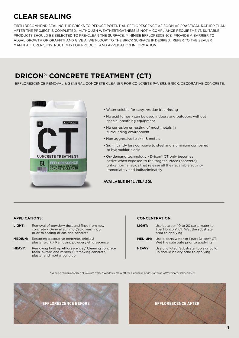
• Water soluble for easy, residue free rinsing
• No acid fumes - can be used indoors and outdoors without special breathing equipment
• No corrosion or rusting of most metals in surrounding environment
• Non aggressive to skin & metals
• Significantly less corrosive to steel and aluminium compared to hydrochloric acid
• On-demand technology - Dricon® Ct only becomes active when exposed to the target surface (concrete) unlike normal acids that release all their available activity immediately and indiscriminately
DrICON® CONCrETE TrEaTMENT (CT) EFFLorESCENCE rEMovAL & gENErAL CoNCrEtE CLEANEr For CoNCrEtE PAvErS, BrICk, DECorAtIvE CoNCrEtE.
LIGHT: use between 10 to 20 parts water to 1 part Dricon® Ct. Wet the substrate prior to applying
MEDIUM: use 4 parts water to 1 part Dricon® Ct. Wet the substrate prior to applying
HEaVY: use undiluted. Substrate, tools or build up should be dry prior to applying
aPPLICaTIONs: CONCENTraTION:
LIGHT: removal of powdery dust and fines from new concrete / general etching (‘acid washing’) prior to sealing bricks and concrete
MEDIUM: restoring decorative concrete, bricks & plaster work / removing powdery efflorescence
HEaVY: removing built up efflorescence / Cleaning concrete tools, pumps and mixers / removing concrete, plaster and mortar build up
EFFLORESCENCE BEFORE EFFLORESCENCE AFTER
* When cleaning anodized aluminium framed windows, mask off the aluminium or rinse any run-off/overspray immediately.
aVaILaBLE IN 1L /5L/ 20L

MOrTar
DrICON® COLOUrED MOrTarsColoured Mortar is an ideal spreadable and workable mortar for all types of masonry, brick and stone work.
5
the minimum requirement for Firth brick veneers is 12.5Mpa.
the volume of water, additives, and mixing time, all need to be
consistent to achieve a quality mortar of an even colour.
If the temperature exceeds 27 degrees Celsius, ensure the
bricks are kept damp for the first 24 hours to prevent rapid
loss of moisture. Discard any mortar which is over 1.5 hours
old, in summer; and for temperatures below 5 degrees Celsius
discard after 2 hrs old. Avoid re-tempering mortar with water.
NZS4210 sect 2.2.2.2 (e).
the correct time to tool a mortar joint is when a clear thumb
print can be made on the surface. If joints are not tooled at the
same moisture content they will vary in colour.
Dricon bagged mortar is recommended for quality control to
ensure compliance with the code. refer to Firth’s “Designer
Brick” brochure for available colours. Firth’s Masonry veneers
Planner is an online tool to help you choose your size of brick
and match it with your choice of coloured mortar.
visit firth.co.nz for more.
MOrTar JOINTs
GrOOVED JOINT
Also known as Concaved or rolled. this type
of joint is formed by using a curved steel
jointing tool. Its recessed profile and tight
seal mean that it is very effective at resisting
moisture penetration. this type of joint
can be good for hiding small irregularities.
Should be tooled to a maximum depth of
6mm after initial stiffening has occurred.
raKED JOINT
For this type of joint the mortar is raked
out and once pointed and tooled shall
not exceed a maximum depth of 6mm.
It is important to compact the mortar to
improve its weather tight performance, this
design creates a form of ledge where water
can pool and therefore should only be used
for internal walls. Not recommended for
exterior walls.
FLUsH JOINT
Firth does not recommend the use of flush joints
unless they are compacted. If the mortar is flush
jointed and not compacted it can lead to the
following issues:
• When brick veneer is to be honed, the mortar
can ‘flick’ out with honing process.
• When brick veneer is to be plastered it can lead
to hairline cracking in the plaster where the
outline of the brick can be seen.
ON SITE MIx RATIO IS THREE BUCkETS OF SAND TO ONE BUCkET OF CEMENT. REMEMBER yOU MAy BE CALLED UPON TO VERIFy yOUR SITE MIx STRENGTH SO CyLINDERS SHOULD BE TAkEN AT REGULAR INTERVALS.
Architectural Mortar is an ideal spreadable and workable mortar for use with Masonry, Bricks and Stone.
• Available in 3 colours• Strength of 12.5MPa after 28 days• Minimises on site waste• Consistent colour & strength throughout the job
• Endorsed by BBFNZ• Meets NZS 4210 Masonry Construction: Materials
and Workmanship
• Available in 15 colours• Strength of 12.5MPa after 28 days• Minimises on site waste• Consistent colour & strength throughout the job
• Endorsed by BBFNZ• Meets NZS 4210 Masonry Construction: Materials
and Workmanship
DrICON® arCHITECTUraL MOrTar
Bricks Notes size (W x H X D) # Bricks Per m2 Bricks per 30kg Bag
MasONrYh10.01 block veneer Cored 390 x 90 x 90 25 24 – 30
10.01 block veneer Cored 390 x 190 x 90 12.5 18 – 24
FIrTHDevonstone® 70 series/Cored 290 x 160 x 70 19.6 40 – 46
Manorstone® 90 series/Cored 390 x 190 x 90 12.5 18 – 24
Focus® Brick & Pioneer Solids 230 x 90 x 75 42.0 33 – 38
CONCAVE RAkED (interior only)FLUSH
MOrTar JOINTs
Raked joints are not recommended for exterior.

JOINT TYPEs
Figure 1 shows some of the tooling details commonly practiced. Some are not recommended for external application because of their poorer weatherproofing properties, but this will be of lesser significance where cavity protects the inner wall.
Because of the positive barrier to ingress of moisture, any of the joint details illustrated in Figure 1 may be applied to external cavity or brick veneer walls without risk to inside finishes. Of the details shown, types A, B and C are suitable for internal or external use. Raked and extruded joints should not be used externally except in cavity or brick veneer construction. Raked joints will also accentuate the normal horizontal rough edge on brick veneer blocks and increase the potential for efflorescence to present.
The flush joint is recommended only for walls which receive a later applied finish or coating.
The joints A, B and C, should only be tooled to a maximum depth of 6mm after initial stiffening has occurred. The delaying of the tooling operation is vital if a tight weatherproof joint is to be produced in horizontal and, particularly, vertical joints.
sTaGE 1
Figure 2 illustrates in an exaggerated way what is happening in the joint and how tooling gives an improved weather tightness. The whole matter of the tooling of external joints is of paramount importance and strict attention to delaying the operation after initial set of the mortar must be given.
66
A GROOVED B WEATHERED C VEED
D RAKED (interior only) E EXTRUDED
FIGURE 1 : JOINT TYPES
F FLUSHED
A GROOVED B WEATHERED C VEED
D RAKED (interior only) E EXTRUDED
FIGURE 1 : JOINT TYPES
F FLUSHED
A GROOVED B WEATHERED C VEED
D RAKED (interior only) E EXTRUDED
FIGURE 1 : JOINT TYPES
F FLUSHED
A GROOVED B WEATHERED C VEED
D RAKED (interior only) E EXTRUDED
FIGURE 1 : JOINT TYPES
F FLUSHED
A GROOVED B WEATHERED C VEED
D RAKED (interior only) E EXTRUDED
FIGURE 1 : JOINT TYPES
F FLUSHED
A GROOVED B WEATHERED C VEED
D RAKED (interior only) E EXTRUDED
FIGURE 1 : JOINT TYPES
F FLUSHED
A GROOVED B WEATHERED C VEED
D RAKED (interior only) E EXTRUDED
FIGURE 1 : JOINT TYPES
F FLUSHED
Reference: NZCMA Masonry Manual www.nzcma.org.nz
FIGURE 2 : TOOLING OF JOINTS
TIME LAPSEUNIT
UNIT
MORTARJOINT
AS LAIDWET
TIME LAPSE:1/2 - 1 1/2 HRS
VARIES WITH WEATHER CONDITIONS
EVAPORATIONOF WATER FROM MORTARCREATES CRACK
TIME LAPSE:FOLLOW STAGE 2 TOOLING IN
SEMI HARDCONDITION REMOULDSMORTAR AND ELIMINATES THE CRACK
FIGURE 2 : TOOLING OF JOINTS
TIME LAPSEUNIT
UNIT
MORTARJOINT
AS LAIDWET
TIME LAPSE:1/2 - 1 1/2 HRS
VARIES WITH WEATHER CONDITIONS
EVAPORATIONOF WATER FROM MORTARCREATES CRACK
TIME LAPSE:FOLLOW STAGE 2 TOOLING IN
SEMI HARDCONDITION REMOULDSMORTAR AND ELIMINATES THE CRACK
FIGURE 2 : TOOLING OF JOINTS
TIME LAPSEUNIT
UNIT
MORTARJOINT
AS LAIDWET
TIME LAPSE:1/2 - 1 1/2 HRS
VARIES WITH WEATHER CONDITIONS
EVAPORATIONOF WATER FROM MORTARCREATES CRACK
TIME LAPSE:FOLLOW STAGE 2 TOOLING IN
SEMI HARDCONDITION REMOULDSMORTAR AND ELIMINATES THE CRACK
Reference: NZCMA Masonry Manual www.nzcma.org.nz
FIGURE 2 : TOOLING OF JOINTS
TIME LAPSEUNIT
UNIT
MORTARJOINT
AS LAIDWET
TIME LAPSE:1/2 - 1 1/2 HRS
VARIES WITH WEATHER CONDITIONS
EVAPORATIONOF WATER FROM MORTARCREATES CRACK
TIME LAPSE:FOLLOW STAGE 2 TOOLING IN
SEMI HARDCONDITION REMOULDSMORTAR AND ELIMINATES THE CRACK
sTaGE 2 sTaGE 3

STACk BOND
RUNNING OR STRETCHER BOND
7
LaYING OPTIONs STACk BOND IS OUTSIDE THE SCOPE OF NZS4229 & NZS 3604 AND THEREFORE REqUIRES SPECIFIC ENGINEERING DESIGN.
To assist engineers a guide for 10series (90mm wide) is available from the New Zealand Concrete Masonry Association website under the Masonry Manual/ Veneers/Veneer - Stack bond. www.nzcma.org.nz
Studs in timber framed walls to be at 400mm centres. Wall ties, to the requirements of NZS 4210, are to be provided at 400mm centres both vertically and horizontally.
Lattice mesh shall be laid continuously in horizontal courses at 800mm maximum vertical centres, commencing no higher than the second course above the brick veneer base.
Lattice mesh shall also be laid in the course or courses directly above and below openings, extending a minimum 800mm past the edge of the opening.
Lap joins in lattice mesh shall be made at midlength of 390mm block units and shall be staggered so that adjacent laps do not occur within the same vertical block stack. Lattice mesh may be discontinued only at control joints.
use purpose made ‘L’ formed lattice mesh at corner intersections.

LaTTICE MEsH WaLL TIE
LaTTIC MEsH LaP DETaIL
8
FIGURE 3: LATTICE MESHreference: NCMA Masonry Manual www.nzcma.org.nz
Note: For a narrower brick use appropriate lattice mesh to get cover
LaYING OPTIONs CONT.
Comprise 2 parallel longitudinal steel rods of minimum 4mm diameter, held apart approximately 55mm on centre by welded cross wires of 2mm diameter, at 200mm centres.
Steel shall have a minimum yield strength of 300 MPa and be hot dip galvanised to minimum 470gm/m2. Mesh to be supplied and installed in minimum 2m length modules, lapped to detail shown in figure below.
BEDDING DETaILs
LATTICE MESH SHALL BE EAGLE WIRE BRICkLOCk, OR EqUIVALENT, AND COMPLy WITH THE FOLLOWING REqUIREMENTS:

Houhora
Keri Keri
Kawakawa
Whangarei
Maungaturoto
Coromandel
Whitianga
Kopu Ngatea
Whangamata
Waihi
KatikatiTauranga
Te Puke
Paengaroa
Rotarua Kawerau
Whakatane
Opotiki
Whatatutu
Waerengaahika
Gisbourne
Wairoa
Taradale
Hastings
Porangahau
Castle Point
Wainuiomata
Blenheim
Seddon
Waiau
Cheviot
Amberley
RangioraWoodendYaldhurst
Christchurch
Leeston
Rangitata River
Temuka
Timaru
Waimate
Duntroon
Puketeraki
Dunedin
Mosgiel
Balclutha
Kaitangata
Winton
Woodlands
Invercargill
Otautau
Tuatapere
Wellington
Silverstream
Shannon
Linton
Sanson
Marton
Waverly
Palmerston North
KapongaEltham
Inglewood
New Plymouth
Otorohanga
Raglan
Hamilton
Maramarua
Taukau
Auckland
Muriwai Beach
Dargaville
Baylys Beach
Opononi
Ahipara
Kaitaia
Stokes Valley
Milford Sound
Haast
Mount Cook
Fox Glacier
Harihari
Otira
Kumara
Stillwater
Karamea
Ngatimoti
Collingwood
Takaka
Motueka
Nelson
Wakefield
WaLL TIEs / zONING GUIDE Wall ties and screws shall be determined by the
durability zone outlined in NZS 3604 and as outlined
in E2/AS1 table 18A and 18C.
zONE B
zONE B
zONE C
zONE D
zONE D
zONE C
9
ZoNE B
ZoNE
YES YES
Note - Zone D includes all offshore Islands, the area within 500m of the coastline of New Zealand, and
those areas shown in white. the map shall be read in conjunction with 4.2.2.
ZoNE C YES YES
ZoNE D & E YES -
316, 316L, or 304 stainless
steel
470 g/m2 galvanising on
mild steel

NOTEs:
1. Maximum masonry tie spacings of 600mm horizontally and 400mm vertically
2. Spacing of ties to be determind by specific engineering design
3. EM may be used if the horizontal spacings do not exceed 400mm and the vertical spacings to not exceed 300mm
4. type B and Prefix E indicate masonry ties manufactured to AS/NZS 2699.1
5. L (Light), M (Medium), h (high) indicate strength capability of ties in AS/NZS 2699.1
6. use seismic zone 2 (minimum) for Christchurch region comprising Christchurch City, Waimakariri District and Selwyn District
reference: Acceptable Solution E2/AS1
COMMENTs
variations in cavity width will require compensating adjustments to the length of masonry tie used.
refer to Brick Weights and Weather Step Dimensions table on page 15.
10
2.7.3 CLASSIFICATION OF TyPE B TIES
Brick veneer ties for use in seismic areas shall be classified in accordance with their characteristic strength and stiffness as show in table 2.
the classification is as follows:
(a) Earthquake light duty (EL).
(b) Earthquake medium duty (EM).
(c) Earthquake heavy duty (Eh).
1
sEIsMIC zONE
rEFEr Nzs
3604
MasONrY BrICK
VENEEr MOrE
THEN 220 KG/M2
EL
tIE tYPE (4)(5)
MAXIMuM SPACINgS (1)
horIZoNtAL vErtICAL
600 400
TABLE 18A SPECIFICATION OF MAxIMUM TIE SPACINGS FOR TyPE B (4) BRICk VENEER TIES
PARAGRAPH 9.2.7
2 (6) EM 600 400
3
4
Eh (3) 600 400
SED (2) SED (2) SED (2)
SED (2)
SED (2)
SED (2)
MasONrY BrICK VENEEr LEss THaN 180 KG/M2
MasONrY BrICK VENEEr 180-220 KG/M2
EM
tIE tYPE (4)(5)
MAXIMuM SPACINgS (1)
horIZoNtAL vErtICAL
600
600
400
Eh (3) 400
Eh (3) 600 400
TABLE 2 TyPE B BRICk VENEER TIES (FLExIBLE OR NON-FLExIBLE)
MINIMuM ChArACtErIStIC StrENgth AND ChArACtErIStIC StIFFNESS uNDEr AXIAL LoADINg
CLassIFICaTION FOr sEIsMIC BrICK TIE
MINIMUM CHaraCTErIsTIC aXIaL sTrENGTH (aT THE
END OF 4TH, 10 MM TENsION CYCLE) kN
MINIMUM CHaraCTErIsTIC aXIaL sTIFFNEss kN/MM
MINIMUM CHaraCTErIsTIC rEsIDUaL sTrENGTH
(aT END OF 15 MM CYCLE) kN
Light duty (EL)
NOTE: type B non-flexible brick veneer ties are known as ‘standard ties’ in New Zealand.
reference AS/NZS 2699.1
0.150 0.500 0.350
Medium duty (EM) 0.175 0.750 0.550
heavy duty (Eh) 0.200 1.500 1.100

11
the tie length is governed by the cavity width and the width of the brick veneer being laid. the tie when fixed should extend to a minimum of half way across the width of the brick but also have a minimum cover of 15mm to the outside. the tie should also have a 5 degree downslope from the frame. ties should also be positioned within 300mm of openings.
Brick veneer shall be attached to wall framing by wall ties. Wall ties and their spacings and embedment shall be in accordance with the requirements of NZS 4210 and E2/AS1 tables 18A, 18B and 18C. Screw fixings shall be minimum 12 gauge, 35mm long hex washer face, galvanised or stainless steel to suit the ties required under table 18C.
LOCaTION PLaCEMENT OF MasONrY TIEs
TABLE 18B PLACEMENT OF WALL TIESPARAGRAPH 9.2.5 AND 9.2.7
unsupported panel sides and edges of openings Within 300mm of panel side or edge
top of brick veneer panels and top of panels under openingsWithin 300mm or two courses (whichever is the smaller) of top of brick
Bottom of brick veneer panel in masonry rebate sealed with liquid applied damp-proof course
Bottom of brick veneer panel supported on steel angle lintel
Within 300mm or two courses (whichever is the smaller) from bottom of brick
Bottom of brick veneer panel in masonry rebate with membrane damp-proof course
NOTES: ties are to be screw fixed (ie. non-impact method) using screws outlined in table 24.
In each of the first two courses
WALL TIES - 9.2.7
Reference: Acceptable Solutions E2/AS1 External Moisture

THE BrICK CaVITY the minimum cavity width is 40mm and the maximum is 75mm – (E2/AS1 Fig 73D and section 9.2.6 Cavities). It’s important to maintain the minimum cavity width of 40mm after allowing for construction tolerances and thickness of wall underlays and sheet bracing. E2/AS1 allows for a maximum overhang of 20mm. Mortar should
not encroach into the cavity more than 5mm (NZS4210).
Reference: Acceptable Solutions E2/AS1 External Moisture
12
111
E X T E R N A L M O I S T U R E
D E P A R T M E N T O F B U I L D I N G A N D H O U S I N G
Acceptable Solut ion E2/AS1
Masonry veneer details Paragraph 9.2.5
Figure 73D:
Amend 5Aug 2011
2 4 D e c e m b e r 2 0 1 1
Errata 2Dec 2011
Errata 2Dec 2011
Errata 2Dec 2011
(h) MASONRY VENEER - DOOR SILL
(i) MASONRY VENEER - FLOOR REBATE DETAIL
(j) MASONRY VENEER - MASONRY BELOW GROUND
brick
brick
brick
brick
FIGURE 73DMASONRy BRICk VENEER DETAILS
(h) MASONRy BRICk VENEER - DOOR SILL
111
E X T E R N A L M O I S T U R E
D E P A R T M E N T O F B U I L D I N G A N D H O U S I N G
Acceptable Solut ion E2/AS1
Masonry veneer details Paragraph 9.2.5
Figure 73D:
Amend 5Aug 2011
2 4 D e c e m b e r 2 0 1 1
Errata 2Dec 2011
Errata 2Dec 2011
Errata 2Dec 2011
(h) MASONRY VENEER - DOOR SILL
(i) MASONRY VENEER - FLOOR REBATE DETAIL
(j) MASONRY VENEER - MASONRY BELOW GROUND
brick
brick
brick
brick
(i) MASONRy BRICk VENEER - FLOOR REBATE DETAIL
Masonry brick veneerMasonry brick veneer wall tiesRefer Table 18B
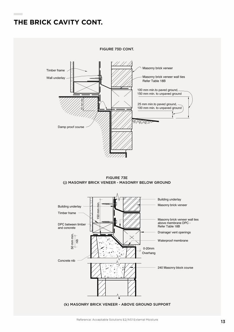
THE BrICK CaVITY CONT.
Reference: Acceptable Solutions E2/AS1 External Moisture13
Masonry brick veneer
Masonry brick veneer wall tiesRefer Table 18B
Masonry brick veneer
Drainage/ vent openings
Timber frame
Building underlay
nib
50 m
m m
in.
Overhang0-20mm
Masonry brick veneer wall tiesabove membrane DPC -Refer Table 18BDPC between timber
and concrete
Concrete nib
Waterproof membrane
240 Masonry block course
150
mm
min
. Building underlay
ScaleChecked by
Drawn by
Date
Project number
http://www.firth.co.nz/ 1 : 5
10/25/2016 9:35:10 AM
Above Ground Support
AM01TECHNICAL DOCUMENTSFirth
01/09/16
Author
Checker
A115
(K) MASONRY VENEER - ABOVE BELOW GROUND
FIGURE 73E(j) MASONRy BRICk VENEER - MASONRy BELOW GROUND
(k) MASONRy BRICk VENEER - ABOVE GROUND SUPPORT
FIGURE 73D CONT.
BRICk WEIGHTS AND WEATHER STEP DIMENSIONS
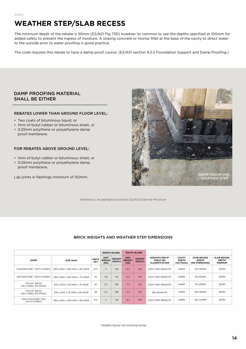
DAMP PROOF ON WEATHER STEP
14
WEaTHEr sTEP/sLaB rECEssthe minimum depth of the rebate is 50mm (E2/AS1 Fig 73D) however its common to see the depths specified at 100mm for added safety to prevent the ingress of moisture. A sloping concrete or mortar fillet at the base of the cavity to direct water to the outside prior to water proofing is good practice.
the code requires this rebate to have a damp proof course. (E2/AS1 section 9.2.5 Foundation Support and Damp Proofing.)
REBATES LOWER THAN GROUND FLOOR LEVEL:
• Two coats of bituminous liquid, or • 1mm of butyl rubber or bituminous sheet, or • 0.25mm polythene or polyethylene damp proof membrane.
FOR REBATES ABOVE GROUND LEVEL:
• 1mm of butyl rubber or bituminous sheet, or • 0.25mm polythene or polyethylene damp proof membrane.
Lap joints in flashings minimum of 150mm.
DAMP PROOFING MATERIAL SHALL BE EITHER
Reference: Acceptable Solutions E2/AS1 External Moisture
148
125
158
188
50MM130-140MM
50MM110-120MM
50MM115-125MM
50MM130-140MM
sLaB rECEss WIDTH
(NO OVErHaNG)
sLaB rECEssDEPTH
MINIMUM
WEIGHT (KG/m2)
390 LoNg x 190 hIgh x 90 WIDE
230 LoNg x 90 hIgh x 75 WIDE
290 LoNg x 160 hIgh x 70 WIDE
230 LoNg x 75 hIgh x 90 WIDE
sIzE (mm)
390 LoNg x 190 hIgh x 90 WIDE
12.5
20
42
49
UNITs(M2)
12.5
11
5.8
3.3
3.3
UNIT WEIGHT
(KG)
11 148
40MM
40MM
40MM
40MM
CaVITY WIDTH
(40-75mm)
40MM 50MM130-140MM
LESS thEN 180kg/M2
LESS thEN 180kg/M2
LESS thEN 180kg/M2
180-220kg/M2
WEIGHTs PEr M2
TaBLE 18a CLassIFICaTION
LESS thEN 180kg/M2
12.2
6.2
3.4
3.4
12.2
UNIT WEIGHT
(KG)
165
133
163
193
165
WEIGHT (KG/m2)
NOrTH IsLaND sOUTH IsLaND
MANorStoNE® (WIth CorES)
DEvoNStoNE® (WIth CorES)
FoCuS® BrICk
(No CorES, No Frog)
FoCuS® BrICk
(No CorES, No Frog)
NaME
ArCh MASoNrY 1001 (WIth CorES)
* Weights kg per m2 including mortar

5 mm min. vent space
Fibre cement sheet or H3plywood soffit closure
Wall underlay
Drainage cavity
6 mm min.
Masonry brick veneer
Cladding over wall underlay
502 mm min. gap
5 mm min. vent space
Fibre cement sheet or H3plywood soffit closure
18 x 18 mm bead (optional)
Drainage cavity
cavity vents (alternative venting)
Scalechecked by
Drawn by
Date
Project number
http://www.firth.co.nz/ 1 : 5
8/29/2016 10:22:42 AM
Soffit Detailing
EB01TEcHNicAL DocUMENTSFirth
04/08/16
Author
checker
A108
CaVITY VENTILaTIONDrainage/weep/vent holes should be a minimum of 75mm high and the width of the mortar joint. they should be installed at centres not exceeding 800mm. If the vent holes are less than 75mm high decrease the spacing to achieve a ventilation area of 1000mm2/m wall length. the cavity shall be ventilated to the outside at the top of walls by either similar vents as at the bottom, or a continuous 5mm minimum gap between the top course and soffit board, with a cover bead to outside that maintains a minimum 2mm gap to masonry (E2/AS1 section 9.2.6 (d) Cavities and Fig 73E). It is good practice to install vent holes under window sills over 2.4m wide. the cavity shall be sealed off from the floor and roof space.
MASONRy BRICk VENEER CANTILEVER UPPER FLOOr
15
FIGURE 73 EMASONRy BRICk VENEER
SOFFIT DETAIL

60 x 60 x 6L 60 x 60 x 6L60 x 60 x 6L 60 x 80 x 6L 60 x 80 x 6L 80 x 80 x 6L
350
60 x 60 x 6L 80 x 80 x 6L80 x 80 x 6L 80 x 80 x 6L 80 x 80 x 6L 80 x 80 x 6L
80 x 80 x 6L 125 x 75 x 6L80 x 80 x 6L 80 x 80 x 8L 90 x 90 x 10L 125 x 75 x 10L
125 x 75 x 6L 125 x 75 x 10L - -125 x 75 x 6L 125 x 75 x 10L
60 x 60 x 6L 60 x 60 x 6L60 x 60 x 6L 60 x 80 x 6L 60 x 80 x 6L 80 x 80 x 6L
80 x 80 x 6L 125 x 75 x 6L80 x 80 x 6L 80 x 80 x 6L 80 x 80 x 8L 90 x 90 x 10L
80 x 80 x 8L 125 x 75 x 10L125 x 75 x 6L 80 x 80 x 10L 125 x 75 x 6L 150 x 90 x 10L
125 x 75 x 6L 125 x 75 x 10L - -125 x 75 x 6L 125 x 75 x 10L
700
70
2000
MaXIMUM HEIGHT OF BrICK VENEEr sUPPOrTED (MM)
MaXIMUM THICKNEss OF MasONrY BrICK VENEEr (MM)
350 700
90
2000
0.800
sPaN OF LINTEL (M) UP
TO:
2.500
3.500
4.500
2.000
3.000
4.000
4.800
BUILDING WRAP
BRICk VENEER
OPENINGs / LINTELsLINTELS CAN BE INSTALLED 2 DIFFERENT WAyS:
1
2
16
Seating as per E2/AS1 section 9.2.9 openings in brick veneer
Minimum seating into adjacent brick of: A) 100mm for spans up to and including 2m
B) 200mm for spans over 2m
ANGLE IS SUPPORTED By THE BRICk
keep the angle 5mm short of the openings at each end to allow for movement
Lintel coach-screwed to timber framing using 75mm x 10mm screws at 400 centres
ANGLE IS FIxED TO THE TIMBER FRAME
All lintels shall comply with the corrosion requirements as in table 18D and exposure zones as in NZS3604.
SEE PAGE 10 FOR MAPS AND zONING GUIDE
TABLE 18E - MASONRy BRICk VENEER LINTEL SIZES (MINIMUM)
DO NOT ATTACHED LINTELS TO TIMBER FRAME
BUILDING WRAP
BRICk VENEER
preferred option
Reference: Acceptable Solutions E2/AS1 External Moisture

Masonry wall tie
Flashing tape overhead flashing upstand
Brick Veneer
Air sealover Pef rod
Galvanised lintel3-5MM Gap
Wall underlayfolded into openingwth flexible flashingtape at canvas
Aluminium head flashingwith 15O slope and20mm upstands to back ofcladding at each end
Sealant between head flashingand window flange in very high andextra high wind zones
7.5mm
35mm coverminimum
10mm cover
Air seal
Frame block
Sill support bar
Sill flashing with dripedge, extend 200mmeach side of window
H3.2 timber kick-outfillet
Flexible flashing tape over wallunderlay behind sill flashing
Window sill, do not seal tomasonry sill
Masonry or tile sill, cantileveredor flush, with min.15º slope. (ReferParagraph 9.2.6 e)
Sill vents to Paragraph 9.2.6
Masonry wall tie
ScaleChecked by
Drawn by
Date
Project number
http://www.firth.co.nz/ 1 : 5
8/29/2016 10:22:42 AM
Window Sill
EB01TECHNICAL DOCUMENTSFirth
04/08/16
Author
Checker
A106
Air seal
Masonry veneer
200
Line of masonry walltie
Jamb flashing
Packers
Wall underlay
Line of head and sillflashings extended200 mm each sideof opening
Scalechecked by
Drawn by
Date
Project number
http://www.firth.co.nz/ 1 : 5
8/29/2016 10:22:42 AM
Window Jamb
EB01TEcHNicAL DocUMENTSFirth
04/08/16
Author
checker
A107
17
FLasHINGsTHE MOST IMPORTANT FLASHINGS ARE AROUND OPENINGS SUCH AS DOORS AND WINDOWS; THE HEAD FLASHING BEING THE CRITICAL ELEMENT. REFER E2/AS1 FIG 73C.
FIGURE 73C - BRICk VENEER WINDOW AND DOOR INSTALLATION
ROOF TO WALL JUNCTION
If a metal head flashing is used and fixed to the framing, ensure it is kept 5mm short at each end, and the ends of the flashing turned up. this will allow for any movement in the framing without interfering with the bricks. A 5 – 10mm gap between the underside of the lintel bar and the flashing allows for both drainage and ventilation eliminating the need for weep holes in the bricks across the head of the opening.
jamb flashings are simple and inexpensive. use a 200mm wide polyethylene flashing, tucked into the joinery flange.
the open end of the flashing is to be held off the building wrap using a kick-out batten or protruding clouts. the junction between the bricks and the joinery does not need to be sealed. the sill flashing is equally important; any moisture driven up the sill brick needs to be stopped from reaching the timber framing and directed into the bottom of the cavity as shown. Extend flashings 200mm past the sides of any openings where practical to do so. (NZS 3604 sect 11.7.7)
Reference: Acceptable Solutions E2/AS1 External Moisture
Galvanize MS. angle
Roofing on underlay
Masonry veneer
Drainage/ vent openings
Flashing
Timber framing
Building underlay
Flashing
ScaleChecked by
Drawn by
Date
Project number
http://www.firth.co.nz/ 1 : 5
10/25/2016 1:08:04 PM
Roof to wall junction
AM01
TECHNICAL DOCUMENTS
Firth
01/09/16
Author
Checker
A117
Brick veneer
Brick veneer
(e) HEAD
(f) SILL
(g) JAMB
TABLE 2.2 MAxIMUM TOLERANCES
Item Tolerances
Deviation from the position shown on plan for a building more than one storey in height
15mm
Deviation from vertical within a storey 10mm per 3m of height
Deviation from vertical in total height of building
20mm
Relative vertical displacement between masonry coursesa) Nominated fair face (one side only) b) Structural face
3mm5mm
Relative displacement between loadbearing walls in adjacent storeys intended to be in vertical alignment
5mm
Deviation from line in plana) In any length up to 10m b) In any length over 10m
5mm10mm total
Deviation of bed joint from horizontala) In any length up to 10m b) In any length over 10m
5mm10mm total
Average thickness of bed joint, cross joint, or perpend ± 3mm on thickness specified
Note: Tolerances shall not breach minimum cavity widths.

18
FIRTH CONTROL JOINT SPECIFICATION
Construction Control joints controlling wall movement shall be achieved by providing a bond break between blocks and mortar at the specified locations.
application this alternative control joint is suitable for all Firth brick veneers except for plaster applications. h10.01 to comply with Firth ‘Brick Construction Detail’ document.
FIrTH CONTrOL JOINT
Installation At each control joint a thin layer of suitable polythene tape or similar shall be placed on top and at ends of each unit covering at least 75% of its width. the polythene layer must cover any cavities within the units. Mortar shall then be placed on the horizontal bed and the end of the unit to be laid.
4.0m Max
More than 2.0m
ScaleChecked by
Drawn by
Date
Project number
http://www.firth.co.nz/ 1 : 50
10/21/2016 11:41:59 AM
Stitch Joint Elevation
AM01TECHNICAL DOCUMENTSFirth
01/09/16
Author
Checker
A116
Location Control joints shall be located at edges of windows closest to 4.0m intervals on each wall. Windows exceeding 2.0m in width shall have a control joint at each end. high windows of less than 800mm deep can be excluded. Spacing on plain walls shall not exceed 5.0m.
FINGER JOINT ELEVATION

Finished groundlevel
4 m
etre
s m
axim
um h
eigh
t of v
enee
r
Finished ground level
4 m
etre
s m
axim
um h
eigh
t of v
enee
r
abov
egr
o und
leve
l7
met
res
max
imum
heig
htof
vene
er
1 SToREy
1 SToREy WiTH PART SToREy
2 SToREy oN MASoNRy 2 SToREy VENEER
Finishedground level
4m
etre
sm
axim
umhe
ight
ofve
neer
7m
etre
sm
axim
umhe
ight
abov
egr
ound
leve
l
Finishedground level
4m
etre
sm
axim
umhe
ight
ofve
neer
7m
etre
sm
axim
umhe
ight
abov
egr
ound
leve
l
Scalechecked by
Drawn by
Date
Project number
http://www.firth.co.nz/ 1 : 20
8/29/2016 10:22:43 AM
Veneer Restriction
EB01TEcHNicAL DocUMENTSFirth
04/08/16
Author
checker
A114
Finished groundlevel
4 m
etre
s m
axim
um h
eigh
t of v
enee
r
Finished ground level
4 m
etre
s m
axim
um h
eigh
t of v
enee
r
abov
egr
o und
leve
l7
met
res
max
imum
heig
htof
vene
er
1 SToREy
1 SToREy WiTH PART SToREy
2 SToREy oN MASoNRy 2 SToREy VENEER
Finishedground level
4m
etre
sm
axim
umhe
ight
ofve
neer
7m
etre
sm
axim
umhe
ight
abov
egr
ound
leve
l
Finishedground level
4m
etre
sm
axim
umhe
ight
ofve
neer
7m
etre
sm
axim
umhe
ight
abov
egr
ound
leve
l
Scalechecked by
Drawn by
Date
Project number
http://www.firth.co.nz/ 1 : 20
8/29/2016 10:22:43 AM
Veneer Restriction
EB01TEcHNicAL DocUMENTSFirth
04/08/16
Author
checker
A11419
FIGURE 73B - MASONRy VENEER HEIGHT LIMITATIONSTWO STOREy BRICk VENEER
these requirements apply when the brick is supported by a timber frame, as stipulated in NZS3604. For masonry bricks refer to manufacturer’s website for two storey design options. If the brick is supported by a masonry structure, NZS4229 permits a brick height of 6.0m for wall and up to 10.0m to the top of any gable. Also refer to E2/AS1 73B for other options.
refer to Firth’s “two Storey Masonry veneer Solutions” and “Devonstone two Storey Construction guide”
TWO STOREY maSOnRY VEnEER DESIGn SOLUTIOn - FIRTH DEVOnSTOnE™ & 70mm maSOnRY VEnEERS
CBI 3311 4261 4273
October 2012
BrICK VENEEr CONsTrUCTION - BUILDING HEIGHTs THE MAxIMUM HEIGHT FOR SINGLE STOREy BRICkS IS 4.0M FROM THE FOUNDATION. AT THE GABLE AREA yOU MAy GO TO A MAxIMUM OF 5.5M TO THE APEx.
Finished groundlevel
4 m
etre
s m
axim
um h
eigh
t of v
enee
r
Finished ground level
4 m
etre
s m
axim
um h
eigh
t of v
enee
r
abov
egr
o und
leve
l7
met
res
max
imum
heig
htof
vene
er
1 SToREy
1 SToREy WiTH PART SToREy
2 SToREy oN MASoNRy 2 SToREy VENEER
Finishedground level
4m
etre
sm
axim
umhe
ight
ofve
neer
7m
etre
sm
axim
umhe
ight
abov
egr
ound
leve
l
Finishedground level
4m
etre
sm
axim
umhe
ight
ofve
neer
7m
etre
sm
axim
umhe
ight
abov
egr
ound
leve
l
Scalechecked by
Drawn by
Date
Project number
http://www.firth.co.nz/ 1 : 20
8/29/2016 10:22:43 AM
Veneer Restriction
EB01TEcHNicAL DocUMENTSFirth
04/08/16
Author
checker
A114
2 SToRy BRick

BrICK VENEEr TOLEraNCEs & aEsTHETIC aPPEaraNCEIT IS POSSIBLE FOR A BRICk VENEER TO BE BUILDING CODE COMPLIANT BUT NOT HAVE THE VISUAL LOOk THAT REFLECTS THE SkILLS OF AN ExPERIENCED BRICkLAyER. THIS IS REFERRED TO AS ‘WORkMANSHIP qUALITy’.
It is important to discuss with your bricklayer the aesthetic look you are hoping to achieve with your brick veneer and if possible, include them in your selection process.
the Brick and Blocklayers Federation recommends that parties to a brick construction enter into a clear, written contract that sets out the expectations of parties including agreed workmanship quality standards, quality checking responsibilities and an agreement on how disputes will be managed – even if it is not a compulsory requirement under legistation.
VIEWING DISTANCE
Due to the nature of bricks, no two bricks are the same and no brick is perfect when examined close-up. AStMC90 has been adopted as the industry standard for viewing brickwork – it states that ‘for exposed wall construction chips and imperfections shall not be evident when viewed from a distance of not less than 6.1m in diffused light’.
CHIPPING
Bricks may be transported several times before arriving onsite and occasionally chipping can occur. Chips are more noticeable on bricks that have a surface colour different from the body of the brick. A workmanship quality standard is achieved if imperfections, including chips, are not visible when viewed from a distance of not less than 6.1m under diffused light as per AStM C90.
New Zealand does not have a standard to assist a Bricklayer to evaluate the level of chipping acceptable in a brick prior to laying however AStM C216-15 has been adopted by BBFNZ.
AStM C216-15 for a general purpose face brick (FBS textured) basically has the following requirements:
• Chips from the edge should not be deeper than 8mm
• Corner chips should not be deeper than 13mm
• When all the length of the chips are added up that the total does not exceed 10% of the perimeter of the brick face (as an example, the accumulative lengths of the chips for a 230mm x 75mm brick shall not exceed 61mm).
Although brick veneers have two faces, it is good practice for Bricklayers to set aside bricks that do not meet this standard and to assess whether to discard it or use it for cuts.
Reference: Brick and Blocklayers Federation New Zealand, “Brick Veneer Best Practice Guide” www.bbfnz.co.nz
20

0800 FIrTH 1 (347841)FIrTH.CO.Nz productspec.net masterspec.net
(C) Firth Industries 2018. All rights reserved. Content in this document is protected under the Copyright Act 1994. No material may be reproduced in whole or in part without the written consent of the copyright holder.
PRODUCTSPEC