maya data sheet - home - ocean opticsoceanoptics.com/.../oem-data-sheet-maya2000prov3.pdf ·...
TRANSCRIPT

020-00000-001-05-201603 1
Maya2000Pro Data Sheet for Versions 3.00.1 and Above
Description The Ocean Optics Maya2000Pro and Maya2000Pro-NIR include the linear CCD-array optical bench,
plus all the circuits necessary for spectrometer operation. The result is a compact, flexible system, with
no moving parts, that's easily integrated as an OEM component.
Note
This data sheet is for Maya2000Pro FPGA and FX2 firmware version 3.00.1 and
above. For Maya2000Pro Spectrometers with firmware below this version, and for the
Maya2000 Spectrometer, please see the Maya2000 and Maya2000Pro Data Sheet.
The Maya2000Pro and Maya2000Pro-NIR Spectrometers are a unique combination of technologies
providing users with high sensitivity for low light-level, UV-sensitive and other scientific applications.
The electronics have been designed for considerable flexibility in connecting to various modules as
well as external interfaces. The Maya2000Pro series spectrometers interface to PCs, PLCs and other
embedded controllers through USB 2.0 or RS-232 communications.
The detector used in the Maya2000Pro series spectrometers are a scientific-grade, back-thinned, CCD
array from Hamamatsu (product number S10420 for Maya2000Pro and S11510 for Maya2000Pro-
NIR). For complete details on these detectors, visit www.Hamamatsu.com.

Maya2000Pro (v3.00.1 and above) Data Sheet
2 020-00000-001-05-201603
The Maya operates from power provided through the USB, or from a separate + 5VDC power supply.
The Maya is a microcontroller-controlled spectrometer, thus all operating parameters are implemented
through software interfacing to the unit.
An optional shutter is available that reduces loss of light caused by adding inline components. The
shutter makes it easier to take dark measurements, especially when using a probe or taking emissive
measurements where it is more difficult to introduce a shutter into the optical path.
Features Back-thinned Hamamatsu detectors
S10420 – high UV Sensitivity in Maya2000Pro
S11510 – high NIR Sensitivity in Maya2000Pro-NIR
Spectrometer Design:
Symmetrical Crossed Czerny Turner
101.6 mm focal length
15 gratings including the HC-1 composite grating
6 slit widths
Electrical Performance:
16 bit, 500kHz A/D Converter
Integration time: 7.2ms – 5s
Embedded microcontroller allows programmatic control of all operating parameters and
standalone operation:
USB 2.0 480Mbps (high-speed) and 12Mbps (full speed)
RS232 115Kbaud
Communication Standards for digital accessories (I2C)
Onboard Pulse Generator:
2 programmable strobe signals for triggering other devices
Software control of nearly all pulse parameters
Onboard GPIO:
10 user-programmable digital I/O
Kensington® security slot
Optional shutter for dark measurements requiring a fast integration time and good
throughput – Specify when ordering
Interchangeable slits
EEPROM storage for:
Wavelength Calibration Coefficients
Linearity Correction Coefficients
Absolute Irradiance Calibration (optional)
Plug-n-Play Interface for PC applications
30-pin connector for interfacing to external products

Maya2000Pro (v3.00.1 and above) Data Sheet
020-00000-001-05-201603 3
Specifications
Specifications Criteria
Physical Specifications:
Physical Dimensions (LxWxH)
Spectrometer Weight
Power Supply Weight
149 mm (5.86 in.) x 109.3 mm (4.30 in.) x 50.4 mm (1.98 in.)
0.96 kg (2.1 lbs.)
0.45 kg (1 lb.)
Power:
Power requirement Supply voltage
Power-up time
500 mA at +5 VDC
4.5 – 5.5 V
~2s depending on code size
Absolute Maximum Ratings:
VCC
Voltage on any pin
+ 5.5 VDC
+4VDC
Spectrometer:
Design
Focal length (input)
Optional shutter activation time
Input Fiber Connector
Gratings
Entrance Slit
Detectors
Pixels (active)
Pixel size
Spectral range
Quantum efficiency -- Maya2000Pro
Quantum efficiency -- Maya2000Pro-NIR
Well Depth
Sensitivity
Filters
Symmetric crossed Czerny-Turner
F/4 101.6 mm
11 ms
SMA 905 to single-strand optical fiber (0.22 NA)
14 different gratings
5, 10, 25, 50, 100, or 200 μm slits. (Slits are optional. In the absence of a slit, the fiber acts as the entrance slit.)
S10420 (Maya2000Pro) or S11510 (Maya2000Pro -NIR)
2048 x 64
196µm2
200 – 1100nm
75% peak@600 nm
85% peak @700 nm
200 Ke-
~0.32 counts/e-
OFLV-MAYAPRO-200 available with HC-1 grating
Spectroscopic:
Integration Time
Dynamic Range (Typical)
Dynamic Range (Guaranteed)
Signal-to-Noise
Dark Noise (single dark spectrum)
Nonlinearity (uncorrected)
Linearity (corrected)
7.2ms – 5s
15000:1+
10000:1
450:1
6 RMS counts (Guaranteed)
~10%
>99.7%
Environmental Conditions:
Temperature Humidity
–30° to +70° C Storage & –0 to +50° C Operation
0% – 90% noncondensing

Maya2000Pro (v3.00.1 and above) Data Sheet
4 020-00000-001-05-201603
Specifications Criteria
Interfaces:
USB
RS-232
USB 2.0, 480 Mbps
3-wire RS-232
Quantum Efficiency of S10420 Detector and S11510 Detector
Optical Performance The following table shows the Maya resolution for various slit sizes.
5 micron Slit
10 micron Slit
25 micron Slit
50 micron Slit
100 micron Slit
100 micron Slit
~1.5 pixels ~2.0 pixels ~2.5 pixels ~4.2 pixels ~8.0 pixels ~15.3 pixels

Maya2000Pro (v3.00.1 and above) Data Sheet
020-00000-001-05-201603 5
Mechanical Diagrams

Maya2000Pro (v3.00.1 and above) Data Sheet
6 020-00000-001-05-201603
Electrical Pinout Listed below is the pin description for the Maya Accessory Connector (J3) located on the front vertical
wall of the unit. The connector is a Pak50TM model from 3M Corp. Headed Connector Part# P50-
030P1-RR1-TG. Mates with part# P50-030S-TGF (requires two: 1.27mm (50 mil) flat ribbon cable:
Recommended 3M 3365 Series)
Pin #
Function Input/Output Description
1 RS232 Rx Input RS232 receive signal – Communicates with a PC over DB9 Pin 3
2 RS232 Tx Output RS232 transmit signal – Communicates with a PC over DB9 Pin 2
3 GPIO (2) Input/Output Reserved
4 N/A N/A Reserved
5 Ground Input/Output Ground
6 I2C SCL Input/Output I2C clock signal for communication to other I2C peripherals
7 GPIO (0) Input/Output Base clock
8 I2C SDA Input/Output I2C data signal for communication to other I2C peripherals
9 GPIO (1) Input/Output Master clock
10 Ext. Trigger In Input TTL input trigger signal
11 GPIO (3) Input/Output Integration clock
12 VCC or 5VIN Input or Output
Input power pin for Maya – When operating via USB, this pin can power other peripherals – Ensure that peripherals comply with USB specifications
13 N/A N/A Reserved
14 VCC or 5VIN Input or Output
Input power pin for Maya – When operating via USB, this pin can power other peripherals – Ensure that peripherals comply with USB specifications
15 SPI Data In Input SPI Master In Slave Out (MISO) signal for communication to other SPI peripherals
16 GPIO (4) Input/Output General Purpose Input Output. Controls the optional shutter.

Maya2000Pro (v3.00.1 and above) Data Sheet
020-00000-001-05-201603 7
Pin #
Function Input/Output Description
17 Single Strobe Output TTL output pulse used as a strobe signal – Has a programmable delay relative to the beginning of the spectrometer integration period
18 GPIO (5) Input/Output Acquire spectra (read enable)
19 N/A N/A Reserved
20 Continuous Strobe
Output TTL output signal used to pulse a strobe – Divided down from the master clock signal
21 N/A Output Reserved
22 GPIO (6) Input/Output Reserved
23 N/A N/A Reserved
24 N/A N/A Reserved
25 Lamp Enable Output TTL signal driven Active HIGH when the Lamp Enable command is sent to the spectrometer
26 GPIO (7) Input/Output Reserved
27 Ground Input/Output Ground
28 GPIO (8) Input/Output A/D trigger
29 Ground Input/Output Ground
30 GPIO (9) Input/Output EPFLAG
Maya2000Pro Spectrometer Detector
The Maya2000Pro contains a Hamamatsu S10420 CCD and the Maya2000Pro-NIR contains a
Hamamatsu S11510 CCD. Both are two-dimensional CCDs. The Maya electronics only support
reading out the device as a 1-D array (e.g. all rows are summed together on chip). The structure of the
Maya2000Pro series spectrometers Hamamatsu CCDs is shown below. The device has 2048 x 64
active pixels and a total of 2068 x 70 pixels.
Pixel Definition
The following is a description of all of the pixels:
Maya2000-Pro Pixels
Pixel Description
0 Unusable
1–3 Dark
4–9 Bevels/unusable
10–2057 Spectrum
2058–2063 Bevels/unusable
2064–2067 Dark

Maya2000Pro (v3.00.1 and above) Data Sheet
8 020-00000-001-05-201603
Maya2000Pro CCD Device structure (64 active vertical pixels and 2048 active horizontal pixels)
Timing Signals (Strobe Signals)
Single Strobe The Single Strobe (SS) signal is a programmable TTL pulse that occurs at a user-determined time
during each integration period. This pulse has a user-defined delay and pulse width. The pulse is only
active if the Lamp Enable command is active. This pulse allows for synchronization of external
devices to the spectrometers integration period. The Strobe delay can range from 0 to 30ms. Timing of
the Single Strobe is based on the start of the integration period (the time between the starts of P1V
vertical clock bursts). Timing for the Single Strobe in External Hardware Trigger mode is shown
below:
Single Strobe (External Hardware Trigger Mode)
TRGDLY is the start of integration after external trigger, adjustable in 500 ns increments (0 – 30 ms).

Maya2000Pro (v3.00.1 and above) Data Sheet
020-00000-001-05-201603 9
The width and delay of the Single Strobe can be adjusted in 500ns increments. The tSSHI is a
programmable delay from trigger to the start of a single strobe. tSSLO defines the width by setting the
delay to clear the single strobe pulse from the trigger.
Similar to the Single Strobe signal in External Hardware Trigger mode, the width and delay of the
Single Strobe in Normal or External Synchronization mode can be adjusted in 500ns increments. In
Normal mode, the start of integration replaces the function of the external trigger signal.
Continuous Strobe
The Continuous Strobe signal is a programmable frequency pulse-train with a 50% duty cycle. It is
programmed by specifying the desired period whose range is 2us to 60s. This signal is continuous
once enabled, but is not synchronized to the Start of Integration or External Trigger Input. The
Continuous Strobe is only active if the Lamp Enable command is active.
Synchronizing Strobe Events
If the application requires more than one pulse per integration period, the user needs to insure the
continuous strobe and integration period are synchronized. The integration time must be set so that an
equal number of strobe events occurs during any given integration period.
Maya Trigger/Acquisition Modes The Maya2000Pro supports 4 triggering modes, including the Normal (free-run) mode, which are set
with the Trigger Mode command. These modes are described below. For detailed information on these
trigger modes, refer to the External Triggering Options document for Spectrometer Firmware versions
3.0 and above located on our website at http://www.oceanoptics.com/technical/External-
Triggering2.pdf. The following paragraphs describe these modes.
For Maya2000Pro firmware versions below 3.0 and for Maya2000, see
http://www.oceanoptics.com/technical/External-Triggering.pdf.
Normal (free-run) Mode: In this mode, the spectrometer will acquire a spectrum based on the
integration period specified through the software interface. This data is made available for
reading as soon as all the data is stored. The spectrometer will then immediately acquire
another spectrum even if one has not been requested. If a new spectrum request has come from
the user, then this spectrum will be available to the user. If a new spectrum has not been
requested by the user, then this spectrum will be deleted and the Maya2000Pro will go into
idle mode waiting for a new spectrum request. If you using strobe enable, the order of
operation is strobe enable then integrate. If the second spectrum is not collected by the user,
the Maya200Pro will send another pulse to the strobe enable pin but will not collect another
spectrum and go into idle mode. While the spectrometer is in the idle mode, new spectra will
not be acquired. When a new spectrum request comes from the user, a new data acquisition
cycle will begin.
Software Trigger Mode: This mode is not supported by the Maya2000Pro.
External Synchronous Mode: In this mode, two external triggers are required to complete a
data acquisition. The first rising edge starts the integration period and the second rising edge
stops the integration and starts the next. Thus, the integration time is the period between the
two external trigger pulses. As in Normal mode, no further spectra are acquired until the original spectrum is read by the user.

Maya2000Pro (v3.00.1 and above) Data Sheet
10 020-00000-001-05-201603
External Hardware Level Trigger Mode: In this mode, a rising edge detected by the
spectrometer from the External Trigger input starts the integration period specified through the software interface. After the integration period, the spectrum is stored in the FIFO buffer and is ready to be read by the user. As long as the trigger level remains active, in a logic one state, back-to-back acquisitions will occur, as in the Normal mode. The spectrometer will continue to behave like Normal mode until the trigger transitions to an inactive level.
External Hardware Edge Trigger Mode: In this mode, a spectrum request has to be sent
first, then the spectrometer waits for a rising edge detected on the External Trigger input to
start the integration period specified through the software interface. After the integration
period, the spectrum is retrieved and is ready to be read by the user. Only one acquisition will
be performed for each External Trigger pulse, no matter what the pulse’s duration is, and the
spectrometer will return to the idle state.
Maya USB Port Interface Communications and Control Information The Maya is a microcontroller-based Miniature Fiber Optic Spectrometer that can communicate via
the Universal Serial Bus. This section contains the necessary command information for controlling
the Maya via the USB interface. This information is only pertinent to users who wish to not utilize
Ocean Optics 32 bit driver to interface to the Maya. Only experienced USB programmers should
attempt to interface to the Maya via these methods.
Hardware Description
The Maya utilizes a Cypress CY7C68013A microcontroller that has a high speed 8051 combined with
an USB2.0 ASIC. Program code and data coefficients are stored in external E2PROM that are loaded
at boot-up via the I2C bus. The microcontroller has 8K of internal RAM and 64K of external SRAM.
Maximum throughput for spectral data is achieved when data flows directly from the external FIFO’s
directly across the USB bus. In this mode the 8051 does not have access to the data and thus no
manipulation of the data is possible.
USB Info
Ocean Optics Vendor ID number is 0x2457 and the Product ID is 0x102A.
Instruction Set
Command Syntax
The list of the commands is shown in the following table followed by a detailed description of each
command. The length of the data depends on the command. All commands are sent to the Maya

Maya2000Pro (v3.00.1 and above) Data Sheet
020-00000-001-05-201603 11
through End Point 1 Out (EP1). All spectra data is acquired through End Point 2 In and all other
queries are retrieved through End Point 1 In (EP1). The endpoints enabled and their order is:
Pipe # Description Type Hi Speed Size (Bytes)
Full Speed Size (Bytes)
Endpoint Address
0 End Point 1 Out Bulk 64 64 0x01
1 End Point 2 In Bulk 512 64 0x82
2 End Point 6 In Unused Unused Unused Unused
3 End Point 1 In Bulk 64 64 0x81
USB Command Summary
EP1 Command Byte Value
Description Version
0x01 Initialize Maya 1.01.0
0x02 Set Integration Time 1.01.0
0x03 Set Strobe Enable Status 1.01.0
0x05 Query Information 1.01.0
0x06 Write Information 1.01.0
0x09 Request Spectra 1.01.0
0x0A Set Trigger Mode 1.01.0
0x0B Query number of Plug-in Accessories Present 1.01.0
0x0C Query Plug-in Identifiers 1.01.0
0x0D Detect Plug-ins 1.01.0
0x60 General I2C Read 1.01.0
0x61 General I2C Write 1.01.0
0x6A Write Register Information 1.01.0
0x6B Read Register Information 1.01.0
0x6D Read Irradiance Calibration Factors 1.01.0
0x6E Write Irradiance Calibration Factors 1.01.0
0xFE Query Information 1.01.0

Maya2000Pro (v3.00.1 and above) Data Sheet
12 020-00000-001-05-201603
USB Command Descriptions
A detailed description of all Maya commands follows. While all commands are sent to EP1 over the
USB port, the byte sequence is command dependent. The general format is the first byte is the
command value and the additional bytes are command specific values.
Byte 0 Byte 1 Byte 2 … Byte n-1
Command Byte
Command Specific
Command Specific
… Command Specific
Initialize Maya
Initializes certain parameters on the Maya and sets internal variables based on the USB
communication speed the device is operating at. This command should be called at the start of every
session however if the user does not call it, it will be executed on the first Request Scan command.
The default values are set as follows
Parameter Default Value
Trigger Mode 0 – Normal Trigger
Byte Format
Byte 0
0x01
Set Integration Time
Sets the Maya integration time in microseconds. The value is a 32-bit value whose acceptable range is
7200 – 65,000,000 µs (65 seconds). If the value is outside this range the value is unchanged.
Byte Format
Byte 0 Byte 1 Byte 2 Byte 3 Byte 4
0x02 LSW-LSB LSW-MSB MSW-LSB MSW-LSB
MSW & LSW: Most/Least Significant Word
MSB & LSB: Most/Least Significant Byte
Set Strobe Enable Status
Sets the Maya Lamp Enable line (J2 pin 25) as follows. The Single Strobe and Continuous Strobe
signals are enabled/disabled by this Lamp Enable Signal.
Data Byte = 0 Lamp Enable Low/Off
Data Byte = 1 Lamp Enable HIGH/On

Maya2000Pro (v3.00.1 and above) Data Sheet
020-00000-001-05-201603 13
Byte Format
Byte 0 Byte 1 Byte 2
0x03 Data byte LSB Data Byte MSB
Query Information
Queries any of the 20 stored spectrometer configuration variables. . The Query command is sent to
End Point 1 Out and the data is retrieved through End Point 1 In. When using Query Information to
read EEPROM slots, data is returned as ASCII text. However, everything after the first byte that is
equal to numerical zero will be returned as garbage and should be ignored.
The Query command is sent to End Point 1 Out and the data is retrieved through End Point 1 In. The
20 configuration variables are indexed as follows:
Configuration Index - Description
0 – Serial Number
1 – 0th order Wavelength Calibration Coefficient
2 – 1st order Wavelength Calibration Coefficient
3 – 2nd
order Wavelength Calibration Coefficient
4 – 3rd
order Wavelength Calibration Coefficient
5 – Stray light constant
6 – 0th order non-linearity correction coefficient
7 – 1st order non-linearity correction coefficient
8 – 2nd
order non-linearity correction coefficient
9 – 3rd
order non-linearity correction coefficient
10 – 4th order non-linearity correction coefficient
11 – 5th order non-linearity correction coefficient
12 – 6th order non-linearity correction coefficient
13 – 7th order non-linearity correction coefficient
14 – Polynomial order of non-linearity calibration
15 – Optical bench configuration info #1: gg fff sss
gg – Grating #, fff – filter wavelength, sss – slit size
16 – Maya configuration info #2: Detector Serial Number
17 – Reserved
18 – Power up Baud Rate Value
19 – User Defined
Byte Format
Byte 0 Byte 1
0x05 Configuration Index

Maya2000Pro (v3.00.1 and above) Data Sheet
14 020-00000-001-05-201603
Return Format (EP1) The data is returned in ASCII format and read in by the host through End Point 1.
Byte 0 Byte 1 Byte 2 Byte 3 … Byte 17
0x05 Configuration Index ASCII byte 0 ASCII byte 1 … ASCII byte 15
Write Information Writes any of the 19 stored spectrometer configuration variables to EEPROM. The 19 configuration
variables are indexed as described in the Query Information. The information to be written is
transferred as ASCII information.
Byte Format
Byte 0 Byte 1 Byte 2 Byte 3 … Byte 17
0x06 Configuration Index ASCII byte 0 ASCII byte 1 … ASCII byte 15
Request Spectra
Initiates spectra acquisition. The Maya will acquire a complete spectra (2068 data values). The data is
returned in bulk transfer mode through EP2. The table below provides the pixel order for the two
different speeds. The pixel values are decoded as described below.
Byte Format
Byte 0
0x09
Return Format The format for the returned spectral data is dependant upon the USB communication speed. The
format for both High Speed (480 Mbps) and Full Speed (12Mbps) is shown below. All pixel values are
16 bit values which are organized in LSB | MSB order. There is an additional packet containing one
value that is used as a flag to insure proper synchronization between the PC and Maya.
Note
Maya2000-Pro has 2068 pixels. It reads out 4609 bytes, some of which are filler:
bytes 0-4135 correspond to pixels 0-2067, bytes 4136-4607 are filler, and byte 4608 is
a sync byte.
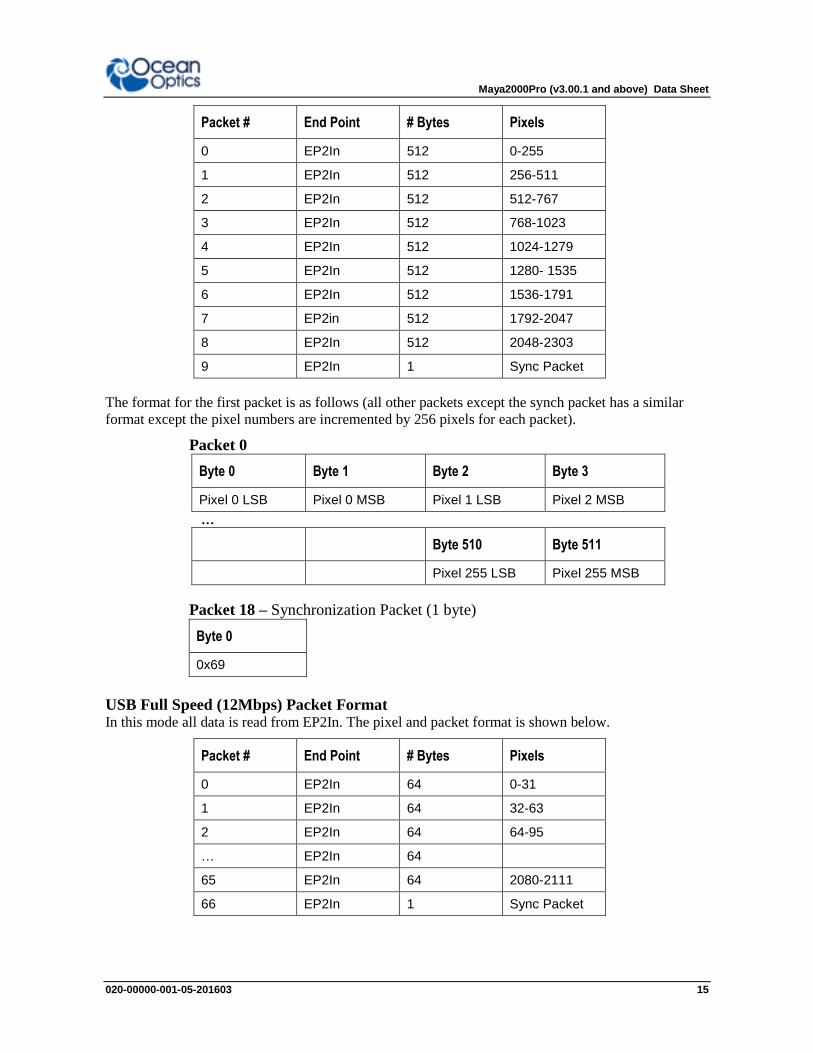
USB High Speed (480Mbps) Packet Format .In this mode, all data is read from EP2In. The packet format is described below.
Maya2000Pro (v3.00.1 and above) Data Sheet
020-00000-001-05-201603 15
Packet # End Point # Bytes Pixels
0 EP2In 512 0-255
1 EP2In 512 256-511
2 EP2In 512 512-767
3 EP2In 512 768-1023
4 EP2In 512 1024-1279
5 EP2In 512 1280- 1535
6 EP2In 512 1536-1791
7 EP2in 512 1792-2047
8 EP2In 512 2048-2303
9 EP2In 1 Sync Packet
The format for the first packet is as follows (all other packets except the synch packet has a similar
format except the pixel numbers are incremented by 256 pixels for each packet).
Packet 0
Byte 0 Byte 1 Byte 2 Byte 3
Pixel 0 LSB Pixel 0 MSB Pixel 1 LSB Pixel 2 MSB
…
Byte 510 Byte 511
Pixel 255 LSB Pixel 255 MSB
Packet 18 – Synchronization Packet (1 byte)
Byte 0
0x69
USB Full Speed (12Mbps) Packet Format In this mode all data is read from EP2In. The pixel and packet format is shown below.
Packet # End Point # Bytes Pixels
0 EP2In 64 0-31
1 EP2In 64 32-63
2 EP2In 64 64-95
… EP2In 64
65 EP2In 64 2080-2111
66 EP2In 1 Sync Packet
Maya2000Pro (v3.00.1 and above) Data Sheet
16 020-00000-001-05-201603
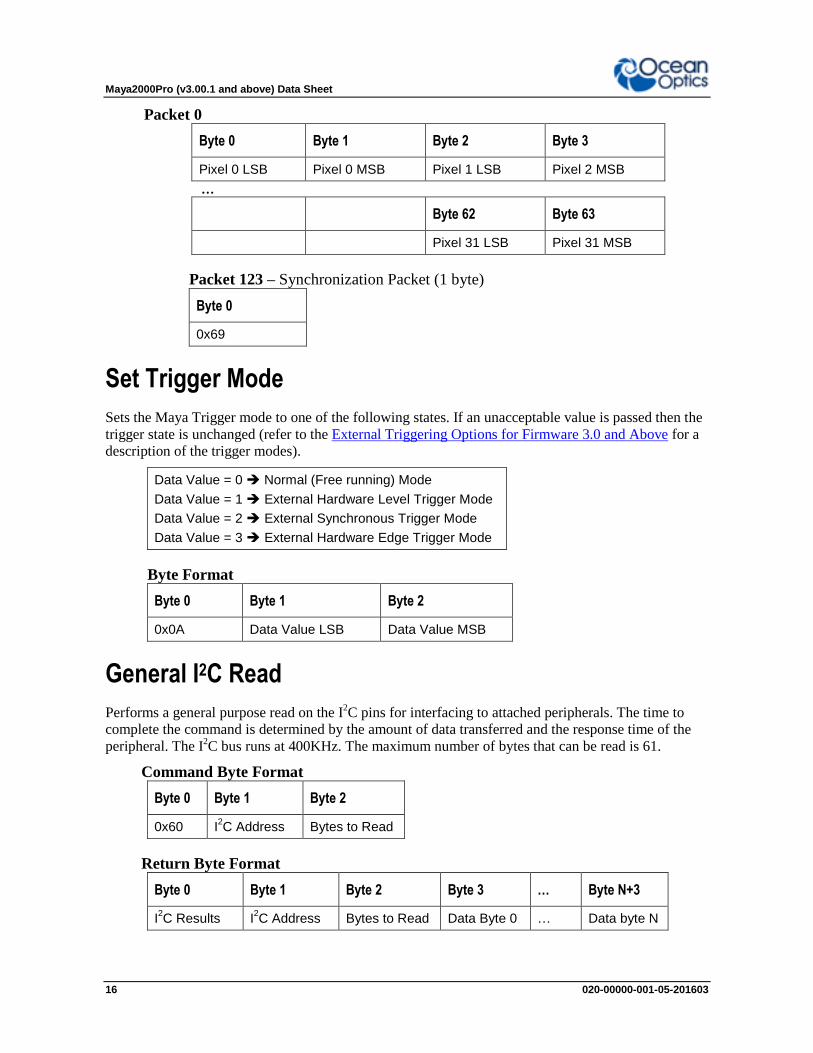
Packet 0
Byte 0 Byte 1 Byte 2 Byte 3
Pixel 0 LSB Pixel 0 MSB Pixel 1 LSB Pixel 2 MSB
…
Byte 62 Byte 63
Pixel 31 LSB Pixel 31 MSB
Packet 123 – Synchronization Packet (1 byte)
Byte 0
0x69
Set Trigger Mode
Sets the Maya Trigger mode to one of the following states. If an unacceptable value is passed then the
trigger state is unchanged (refer to the External Triggering Options for Firmware 3.0 and Above for a
description of the trigger modes).
Data Value = 0 Normal (Free running) Mode
Data Value = 1 External Hardware Level Trigger Mode
Data Value = 2 External Synchronous Trigger Mode
Data Value = 3 External Hardware Edge Trigger Mode
Byte Format
Byte 0 Byte 1 Byte 2
0x0A Data Value LSB Data Value MSB
General I2C Read
Performs a general purpose read on the I2C pins for interfacing to attached peripherals. The time to
complete the command is determined by the amount of data transferred and the response time of the
peripheral. The I2C bus runs at 400KHz. The maximum number of bytes that can be read is 61.
Command Byte Format
Byte 0 Byte 1 Byte 2
0x60 I2C Address Bytes to Read
Return Byte Format
Byte 0 Byte 1 Byte 2 Byte 3 … Byte N+3
I2C Results I
2C Address Bytes to Read Data Byte 0 … Data byte N
Maya2000Pro (v3.00.1 and above) Data Sheet
020-00000-001-05-201603 17
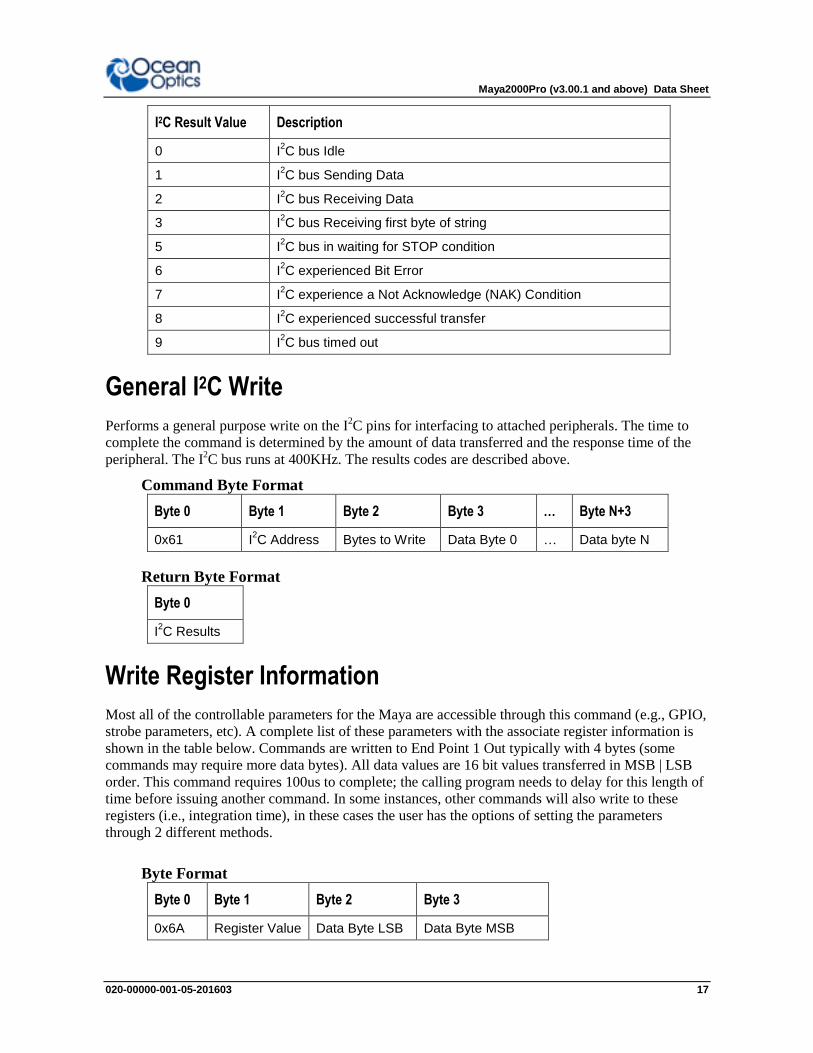
I2C Result Value Description
0 I2C bus Idle
1 I2C bus Sending Data
2 I2C bus Receiving Data
3 I2C bus Receiving first byte of string
5 I2C bus in waiting for STOP condition
6 I2C experienced Bit Error
7 I2C experience a Not Acknowledge (NAK) Condition
8 I2C experienced successful transfer
9 I2C bus timed out
General I2C Write
Performs a general purpose write on the I2C pins for interfacing to attached peripherals. The time to
complete the command is determined by the amount of data transferred and the response time of the
peripheral. The I2C bus runs at 400KHz. The results codes are described above.
Command Byte Format
Byte 0 Byte 1 Byte 2 Byte 3 … Byte N+3
0x61 I2C Address Bytes to Write Data Byte 0 … Data byte N
Return Byte Format
Byte 0
I2C Results
Write Register Information
Most all of the controllable parameters for the Maya are accessible through this command (e.g., GPIO,
strobe parameters, etc). A complete list of these parameters with the associate register information is
shown in the table below. Commands are written to End Point 1 Out typically with 4 bytes (some
commands may require more data bytes). All data values are 16 bit values transferred in MSB | LSB
order. This command requires 100us to complete; the calling program needs to delay for this length of
time before issuing another command. In some instances, other commands will also write to these
registers (i.e., integration time), in these cases the user has the options of setting the parameters
through 2 different methods.
Byte Format
Byte 0 Byte 1 Byte 2 Byte 3
0x6A Register Value Data Byte LSB Data Byte MSB

Maya2000Pro (v3.00.1 and above) Data Sheet
18 020-00000-001-05-201603
Register
Address Description
Default Value
Min Value
Max Value
Time Base
0x00*
Master Clock Counter Divisor
6 1 0xFFFF 48MHz
0x04 FPGA Firmware Version (Read Only)
0x08 Continuous Strobe Timer Interval Divisor
48000 0 0xFFFF
Continuous Strobe Base Clock
(see Register 0x0C)
0x0C Continuous Strobe Base Clock Divisor
4800 0 0xFFFF 48MHz
0x10*
Integration Period LSB Divisor
1000 0 0xFFFF 1MHz
0x14
Set base_clk or base_clkx2
0: base_clk
1: base_clkx2
1 0 1 N/A
0x18*
Integration Period MSB Divisor
10 0 0xFFFF
Integration Period Base Clock
(see Register 0x10)
0x20* Reserved
0x28 Reserved
0x2C&*
Reserved
0x30 Reserved
0x38 Single Strobe High Clock Transition Delay Count
0 0 0xFFFF 2MHz
0x3C Single Strobe Low Clock Transition Delay Count
3000 0xBB8
0 0xFFFF 2MHz
0x40 Lamp Enable 0 0 1 N/A
0x48
GPIO Mux Register
0: pin is GPIO pin
1: pin is alternate function
0 0 0x03FF N/A
0x50
GPIO Output Enable
1: pin is output
0: pin is input
0 0 0x03FF N/A

Maya2000Pro (v3.00.1 and above) Data Sheet
020-00000-001-05-201603 19
Register
Address Description
Default Value
Min Value
Max Value
Time Base
0x54
GPIO Data Register
For Ouput: Write value of signal
For Input: Read current GPIO state
0 0 0x03FF N/A
0x58 Reserved
0x60
Bit*(0) => Reserved 1 0 1 N/A
Bit*(1) => Reserved
DO NOT MODIFY 0 0 1 N/A
Bit*(2) => Reserved
DO NOT MODIFY 1 0 1 N/A
Bit*(3) => Reserved
DO NOT MODIFY 0 0 1 N/A
Bit*(4) => Reserved
DO NOT MODIFY 0 0 1 N/A
0x2C
Trigger Mode
0: Normal (free running)
1: External HW
2: External Synchronous
3: External HW Edge
0 0 3 N/A
Notes: * - User should not change these values because spectrometer performance can be effected.
This information is included just for completeness
& - These values are controlled by other command interfaces to the Maya (i.e Set integration
time command).
Read Register Information
Reads the values from any of the registers above. This command is sent to End Point 1 Out and the
data is retrieved through End Point 1 In.
Byte Format
Byte 0 Byte 1
0x6B Register Value
Return Format (EP1In)
Byte 0 Byte 1 Byte 2
Register Value Value MSB Value LSB

Maya2000Pro (v3.00.1 and above) Data Sheet
20 020-00000-001-05-201603
Read Irradiance Factors
Reads 60 bytes of data, which is utilized for Irradiance Calibration information from the desired
EEPROM memory address.
Byte Format
Byte 0 Byte 1 Byte 2
0x6D EEPROM Address LSB EEPROM Address MSB
Return Byte Format
Byte 0 Byte 1 … Byte 59
Byte 0 Byte 1 … Byte 59
Write Irradiance Factors Write 60 bytes of data, which is utilized for Irradiance Calibration information to the desired
EEPROM memory address.
Byte Format
Byte 0 Byte 1 Byte 2 Byte 3 … Byte 62
0x6E EEPROM Address LSB EEPROM Address MSB Byte 0 … Byte 59
Query Status Returns a packet of information, which contains the current operating information. The structure of the
status packet is given below.
Byte Format
Byte 0
0xFE
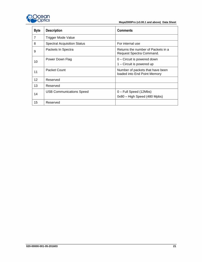
Return Format The data is returned in Binary format and read in by the host through End Point 1 In. The structure for
the return information is as follows
Byte Description Comments
0-1 Number of Spectral Data Values – WORD(s) LSB | MSB order
2-5 Integration Time - WORD Integration time in s – LSW | MSW.
Within each word order is LSB | MSB
6 Lamp Enable 0 – Signal LOW
1 – Signal HIGH
Maya2000Pro (v3.00.1 and above) Data Sheet
020-00000-001-05-201603 21
Byte Description Comments
7 Trigger Mode Value
8 Spectral Acquisition Status For internal use
9 Packets In Spectra Returns the number of Packets in a
Request Spectra Command.
10 Power Down Flag 0 – Circuit is powered down
1 – Circuit is powered up
11 Packet Count Number of packets that have been
loaded into End Point Memory
12 Reserved
13 Reserved
14 USB Communications Speed 0 – Full Speed (12Mbs)
0x80 – High Speed (480 Mpbs)
15 Reserved

Maya2000Pro (v3.00.1 and above) Data Sheet
22 020-00000-001-05-201603
Appendix A:
Maya2000Pro Serial Port Interface Communications and Control Information
Overview
The Maya2000Pro is a microcontroller-based miniature fiber optic spectrometer, which can
communicate via the Universal Serial Bus or RS-232. This document contains the necessary command
information for controlling the MAYA2000PRO via the RS-232 interface.
Hardware Description
The Maya2000Pro utilizes a Cypress FX2 microcontroller, which has a high speed 8051, combined
with an USB ASIC. Program code and data coefficients are stored in external EEPROM, which are
loaded at boot-up via the I2C bus.
Instruction Set
Command Syntax
The list of the commands is shown in the following table along with the microcode version number
they were introduced with. All commands consist of an ASCII character passed over the serial port,
followed by some data. The length of the data depends on the command. The format for the data is
either ASCII or binary (default). The ASCII mode is set with the “a” command and the binary mode
with the “b” command. To insure accurate communications, all commands respond with an ACK
(ASCII 6) for an acceptable command or a NAK (ASCII 21) for an unacceptable command (i.e. data
value specified out of range).
In the ASCII data value mode, the Maya2000Pro “echoes” the command back out the RS-232 port. In
ASCII data mode the device transmits a prompt “>” to show that is waiting for a command. In binary
mode all data, except where noted, passes as 16-bit unsigned integers (WORDs) with the MSB
followed by the LSB. By issuing the “v command” (Version number query), the data mode can be
determined by viewing the response (ASCII or binary).
In a typical data acquisition session, the user sends commands to implement the desired spectral
acquisition parameters (integration time, etc.). Then the user sends commands to acquire spectra (S
command) with the previously set parameters. If necessary, the baud rate can be changed at the
beginning of this sequence to speed up the data transmission process.

Maya2000Pro (v3.00.1 and above) Data Sheet
020-00000-001-05-201603 23
Command Summary
Letter Description Version
A Adds scans 3.00.1
B Set Pixel Boxcar 3.00.1
C
D
E
F
G Set Data Compression 3.00.1
H
I Sets integration time(16-bit resolution) 3.00.1
J Sets Lamp Enable Line 3.00.1
K Changes baud rate 3.00.1
L Clear Memory
M
N
O
P Partial Pixel Mode 3.00.1
Q Initialize Spectrometer
R
S Starts spectral acquisition with previously set parameters 3.00.1
T Sets trigger mode 3.00.1
U
V
W Write to FPGA Register 3.00.1
X
Y
Z
a Set ASCII mode for data values 3.00.1
b Set binary mode for data values 3.00.1
i Set integration time(32-bit resolution) 3.00.1
k Sets Checksum mode 3.00.1
v Provides microcode version # 3.00.1

Maya2000Pro (v3.00.1 and above) Data Sheet
24 020-00000-001-05-201603
Letter Description Version
x Sets calibration coefficients 3.00.1
? Queries parameter values 3.00.1
Command Descriptions
A detailed description of all Maya2000Pro commands follows. The {} indicates a data value which is
interpreted as either ASCII or binary (default). The default value indicates the value of the parameter
upon power up.
Add Scans
Description: Sets the number of discrete spectra to be summed together.
Command Syntax: A{DATA WORD}
Response: ACK or NAK
Range: 1-65000
Default value: 1
Response: ACK or NAK
Pixel Boxcar Width
Description: Sets the number of pixels to be averaged together. A value of n specifies the averaging of
n pixels to the right and n pixels to the left. This routine uses 32-bit integers so that intermediate
overflow will not occur; however, the result is truncated to a 16-bit integer prior to transmission of the
data. This math is performed just prior to each pixel value being transmitted out. Values greater than
~3 will exceed the idle time between values and slow down the overall transfer process.
Command Syntax: B{DATA WORD}
Response: ACK or NAK
Range: 0-15
Default value: 0
Response: ACK or NAK

Maya2000Pro (v3.00.1 and above) Data Sheet
020-00000-001-05-201603 25
Set Data Compression
Description: Specifies whether the data transmitted from the Maya2000Pro should be compressed to
speed data transfer rates. For more information on Maya2000Pro Data Compression, see Technical
Note 1.
Command Syntax: G{DATA WORD}
Response: ACK or NAK
Range: 0 – Compression off
!0 – Compression on
Default value: 0
Response: ACK or NAK
Integration Time (16-Bit)
Description: Sets the Maya2000Pro’s integration time, in milliseconds, to the value specified. This
command is limited to a 16 bit value. If a larger integration time is required, utilize the 32 bit version
(lower case I command)
Command Syntax: I{16 bit DATA WORD}
Response: ACK or NAK
Range: 8 – 65,000
Default value: 20
Integration Time(32-Bit)
Same as above command(I) but uses 32-bit values and is in microseconds.
Command Syntax: i{DATA DWORD}
Value: 7200 - 65,000,000
Response: ACK or NAK
Default value: 20,000
Lamp Enable
Description: Sets the Maya2000Pro’s Lamp Enable line to the value specified
Command Syntax: J{DATA WORD}
Value: 0 = Light source/strobe off—Lamp Enable low
1 = Light source/strobe on—Lamp Enable high
Response: ACK or NAK
Default value: 0

Maya2000Pro (v3.00.1 and above) Data Sheet
26 020-00000-001-05-201603
Baud Rate
Description: Sets the Maya2000Pro’s baud rate.
Command Syntax: K{DATA WORD}
Value: 0=2400 1=4800 2=9600 3=19200
4=38400 5=Not Supported 6=115,200 7=230,400
Response: See below
Default value: 2
When changing baud rates, the following sequence must be followed:
1. Controlling program sends K with desired baud rate, communicating at the old baud rate
2. A/D responds with ACK at old baud rate, otherwise it responds with NAK and the process is
aborted
3. Controlling program waits longer than 50 milliseconds
4. Controlling program sends K with desired baud rate, communicating at the new baud rate
5. A/D responds with ACK at new baud rate, otherwise it responds with NAK and old baud rate
is used
Notes
If a deviation occurs at any step, the previous baud rate is used.
The power-up Baud rate can be set by setting the EEPROM Memory slot to the
desired value (i.e., 6 for a value of 115,200 Baud)

Maya2000Pro (v3.00.1 and above) Data Sheet
020-00000-001-05-201603 27
Pixel Mode
Description: Specifies which pixels are transmitted. While all pixels are acquired on every scan, this
parameter determines which pixels will be transmitted out the serial port.
Command Syntax: P{DATA WORD}
Value:
Description
0 = all 1024 pixels
1 = every nth pixel with no averaging
2 = N/A
3 = pixel x through y every n pixels
4 = up to 10 randomly selected pixels
between 0 and 1023 (denoted p1, p2, … p10)
Example
P 0 (spaces for clarity only)
P 1<Enter>
N<Enter>
P 2<Enter>
N<Enter >
P3<Enter>
x<Enter>
y<Enter>
n<Enter>
P 4<Enter>
n<Enter>
p1<Enter>
p2<Enter>
p3<Enter> …
p10<Enter>
Response: ACK or NAK
Default value: 0
Note
Since most applications only require a subset of the spectrum, this mode can greatly
reduce the amount of time required to transmit a spectrum while still providing all of
the desired data. This mode is helpful when interfacing to PLCs or other processing
equipment.
Maya2000Pro (v3.00.1 and above) Data Sheet
28 020-00000-001-05-201603
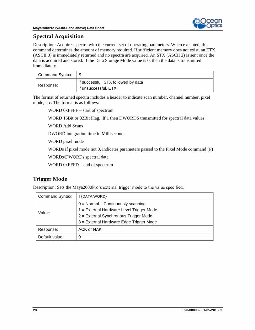
Spectral Acquisition
Description: Acquires spectra with the current set of operating parameters. When executed, this
command determines the amount of memory required. If sufficient memory does not exist, an ETX
(ASCII 3) is immediately returned and no spectra are acquired. An STX (ASCII 2) is sent once the
data is acquired and stored. If the Data Storage Mode value is 0, then the data is transmitted
immediately.
Command Syntax: S
Response: If successful, STX followed by data
If unsuccessful, ETX
The format of returned spectra includes a header to indicate scan number, channel number, pixel
mode, etc. The format is as follows:
WORD 0xFFFF – start of spectrum
WORD 16Bit or 32Bit Flag. If 1 then DWORDS transmitted for spectral data values
WORD Add Scans
DWORD integration time in Milliseconds
WORD pixel mode
WORDs if pixel mode not 0, indicates parameters passed to the Pixel Mode command (P)
WORDs/DWORDs spectral data
WORD 0xFFFD – end of spectrum
Trigger Mode
Description: Sets the Maya2000Pro’s external trigger mode to the value specified.
Command Syntax: T{DATA WORD}
Value:
0 = Normal – Continuously scanning
1 = External Hardware Level Trigger Mode
2 = External Synchronous Trigger Mode
3 = External Hardware Edge Trigger Mode
Response: ACK or NAK
Default value: 0

Maya2000Pro (v3.00.1 and above) Data Sheet
020-00000-001-05-201603 29
Write FPGA Register
Description: Writes a value to an FPGA Register. The register map is defined in the USB command
set section.
Command Syntax: W{Register Address: WORD}{Register Value: WORD}
Value:
Response: ACK or NAK
Default value N/A
Note
To query a register value, issue ?W{Register Address}.
ASCII Data Mode
Description: Sets the mode in which data values are interpreted to be ASCII. Only unsigned integer
values (0 – 65535) are allowed in this mode and the data values are terminated with a carriage return
(ASCII 13) or linefeed (ASCII 10). In this mode the Maya2000Pro “echoes” the command and data
values back out the RS-232 port.
Command Syntax: aA
Response: ACK or NAK
Default value N/A
Notes
The command requires that the string “aA” be sent without any CR or LF. This is an
attempt to insure that this mode is not entered inadvertently.
A legible response to the Version number query (v command) indicates the
Maya2000Pro is in the ASCII data mode.
Binary Data Mode
Description: Sets the mode in which data values are interpreted to be binary. Only 16 bit unsigned
integer values (0 – 65535) are allowed in this mode with the MSB followed by the LSB
Command Syntax: bB
Response: ACK or NAK
Default value Default at power up – not changed by Q command
Maya2000Pro (v3.00.1 and above) Data Sheet
30 020-00000-001-05-201603
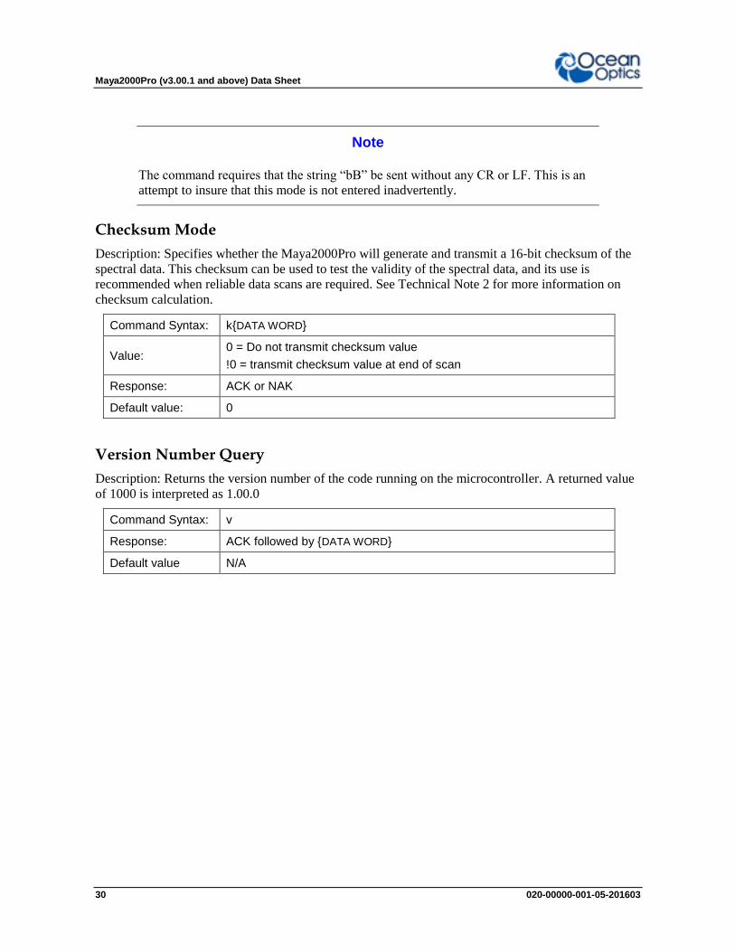
Note
The command requires that the string “bB” be sent without any CR or LF. This is an
attempt to insure that this mode is not entered inadvertently.
Checksum Mode
Description: Specifies whether the Maya2000Pro will generate and transmit a 16-bit checksum of the
spectral data. This checksum can be used to test the validity of the spectral data, and its use is
recommended when reliable data scans are required. See Technical Note 2 for more information on
checksum calculation.
Command Syntax: k{DATA WORD}
Value: 0 = Do not transmit checksum value
!0 = transmit checksum value at end of scan
Response: ACK or NAK
Default value: 0
Version Number Query
Description: Returns the version number of the code running on the microcontroller. A returned value
of 1000 is interpreted as 1.00.0
Command Syntax: v
Response: ACK followed by {DATA WORD}
Default value N/A

Maya2000Pro (v3.00.1 and above) Data Sheet
020-00000-001-05-201603 31
Calibration Constants
Description: Writes one of the 16 possible calibration constant to EEPROM. The calibration constant
is specified by the first DATA WORD which follows the x. The calibration constant is stored as an
ASCII string with a max length of 15 characters. The string is not check to see if it makes sense.
Command Syntax: x{DATA WORD}{ASCII STRING}
Value:
DATA WORD Index description
0 – Serial Number
1 – 0th order Wavelength Calibration Coefficient
2 – 1st order Wavelength Calibration Coefficient
3 – 2nd
order Wavelength Calibration Coefficient
4 – 3rd
order Wavelength Calibration Coefficient
5 – Stray light constant
6 – 0th order non-linearity correction coefficient
7 – 1st order non-linearity correction coefficient
8 – 2nd
order non-linearity correction coefficient
9 – 3rd
order non-linearity correction coefficient
10 – 4th order non-linearity correction coefficient
11 – 5th order non-linearity correction coefficient
12 – 6th order non-linearity correction coefficient
13 – 7th order non-linearity correction coefficient
14 – Polynomial order of non-linearity calibration
15 – Optical bench configuration: gg fff sss
gg – Grating #, fff – filter wavelength, sss – slit size
16 – Maya2000Pro configuration: AWL V
A – Array coating Mfg, W – Array wavelength (VIS, UV, OFLV), L – L2 lens installed, V – CPLD Version
17 – Reserved
18 – Startup Baud Rate value
19 – Reserved
Response: ACK or NAK
Default value: N/A
Note
To query the constants, use the ?x{DATA WORD} format to specify the desired
constant. To query all coefficients issue ?x-1 command.

Maya2000Pro (v3.00.1 and above) Data Sheet
32 020-00000-001-05-201603
Query Variable
Description: Returns the current value of the parameter specified. The syntax of this command
requires two ASCII characters. The second ASCII character corresponds to the command character
which sets the parameter of interest (acceptable values are B, A, I, K, T, J, y). A special case of this
command is ?x (lower case) which requires an additional data word bee passed to indicate which
calibration constant is to be queried.
Command Syntax: ?{ASCII character}
Response: ACK followed by {DATA WORD}
Default value: N/A
Examples
Below are examples on how to use some of the commands. Commands are in BOLD and descriptions
are in parenthesis. For clarity, the commands are shown in the ASCII mode (a command) instead of
the default binary mode.
The desired operating conditions are: acquire every 4th pixel from the spectrometer with a 200ms
integration time, set number of scan to add to 5 and operate at 115,200 Baud.
aA (Set ASCII Data Mode)
> K6<CR> (Start baud rate change to 115,200)
Wait for ACK, change to 115200, wait for 20ms
K6<CR> (Verify command, communicate at 115200)
A2<CR> (Add 5 spectra)
I200<CR> (Set integration time to 200ms)
P1<CR> (Pixel Mode 1...
4<CR> every 4 pixels)
> S (Acquire spectra)
… Repeat as necessary

Maya2000Pro (v3.00.1 and above) Data Sheet
020-00000-001-05-201603 33
Application Tips
During the software development phase of a project, the operating parameters of the
Maya2000Pro may become out-of-synch with the controlling program. It is good practice to
cycle power on the Maya2000Pro when errors occur.
If you question the state of the Maya2000Pro, you can transmit a space (or another non-
command) using a terminal emulator. If you receive a NAK, the Maya2000Pro is awaiting a
command; otherwise, it is still completing the previous command.
For Windows users, use HyperTerminal as a terminal emulator after selecting the following:
1. Select File | Properties.
2. Under Connect using, select Direct to Com x.
3. Click Configure and match the following Port Settings:
Bits per second (Baud rate): Set to desired rate
Data bits: 8
Parity: None
Stop bits: 1
Flow control: None
Click OK in Port Settings and in Properties dialog boxes.

Maya2000Pro (v3.00.1 and above) Data Sheet
34 020-00000-001-05-201603