mb manual ga-990fxa-ud3 v.4.0 e
DESCRIPTION
Manual inglés para Ga-990fxaTRANSCRIPT

GA-990FXA-UD3
User's ManualRev. 400112ME-990FXA3-4001R
Motherboard
GA
-990FXA
-UD
3
Apr. 30, 2013
Apr. 30, 2013
Motherboard
GA
-990FXA-U
D3
Copyright© 2013 GIGA-BYTE TECHNOLOGY CO., LTD. All rights reserved.The trademarks mentioned in this manual are legally registered to their respective owners.
DisclaimerInformation in this manual is protected by copyright laws and is the property of GIGABYTE.Changes to the specifications and features in this manual may be made by GIGABYTE without prior notice.
No part of this manual may be reproduced, copied, translated, transmitted, or published in any form or by any means without GIGABYTE's prior written permission.
Documentation ClassificationsIn order to assist in the use of this product, GIGABYTE provides the following types of docu-mentations:
� For quick set-up of the product, read the Quick Installation Guide included with the product. � For detailed product information, carefully read the User's Manual.
For product-related information, check on our website at: http://www.gigabyte.com
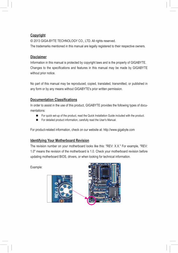
Identifying Your Motherboard RevisionThe revision number on your motherboard looks like this: "REV: X.X." For example, "REV: 1.0" means the revision of the motherboard is 1.0. Check your motherboard revision before updating motherboard BIOS, drivers, or when looking for technical information.
Example:
- 4 -
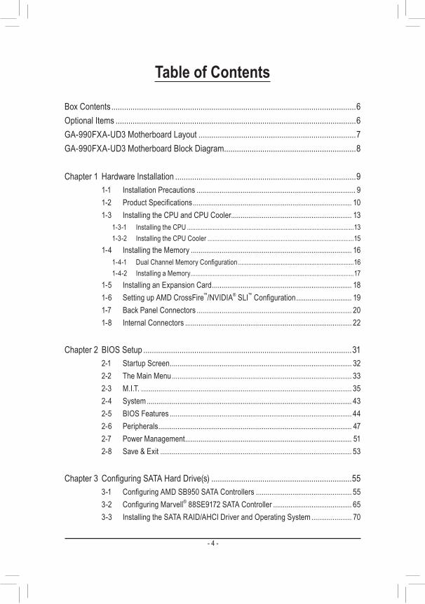
Table of Contents
Box Contents ...................................................................................................................6Optional Items .................................................................................................................6GA-990FXA-UD3 Motherboard Layout ..........................................................................7GA-990FXA-UD3 Motherboard Block Diagram ..............................................................8
Chapter 1 Hardware Installation .....................................................................................91-1 Installation Precautions ................................................................................... 91-2 ProductSpecifications ................................................................................... 101-3 Installing the CPU and CPU Cooler............................................................... 13
1-3-1 Installing the CPU ..................................................................................................131-3-2 Installing the CPU Cooler ......................................................................................15
1-4 Installing the Memory .................................................................................... 161-4-1 DualChannelMemoryConfiguration ....................................................................161-4-2 Installing a Memory ................................................................................................17
1-5 Installing an Expansion Card ......................................................................... 181-6 Setting up AMD CrossFire™/NVIDIA® SLI™Configuration ............................. 191-7 Back Panel Connectors ................................................................................. 201-8 Internal Connectors ....................................................................................... 22
Chapter 2 BIOS Setup ..................................................................................................312-1 Startup Screen ............................................................................................... 322-2 The Main Menu .............................................................................................. 332-3 M.I.T. .............................................................................................................. 352-4 System ........................................................................................................... 432-5 BIOS Features ............................................................................................... 442-6 Peripherals ..................................................................................................... 472-7 Power Management ....................................................................................... 512-8 Save & Exit .................................................................................................... 53
Chapter3 ConfiguringSATAHardDrive(s) ..................................................................553-1 ConfiguringAMDSB950SATAControllers .................................................. 553-2 ConfiguringMarvell® 88SE9172 SATA Controller ......................................... 653-3 Installing the SATA RAID/AHCI Driver and Operating System ..................... 70
- 5 -
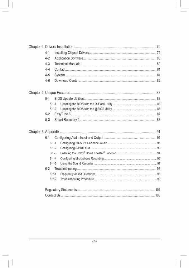
Chapter 4 Drivers Installation .......................................................................................794-1 Installing Chipset Drivers ............................................................................... 794-2 Application Software ...................................................................................... 804-3 Technical Manuals ......................................................................................... 804-4 Contact........................................................................................................... 814-5 System ........................................................................................................... 814-6 Download Center ........................................................................................... 82
Chapter 5 Unique Features ...........................................................................................835-1 BIOS Update Utilities ..................................................................................... 83
5-1-1 Updating the BIOS with the Q-Flash Utility .......................................................... 835-1-2 Updating the BIOS with the @BIOS Utility ........................................................... 86
5-2 EasyTune 6 .................................................................................................... 875-3 Smart Recovery 2 .......................................................................................... 88
Chapter 6 Appendix ......................................................................................................916-1 ConfiguringAudioInputandOutput .............................................................. 91
6-1-1 Configuring2/4/5.1/7.1-ChannelAudio ..................................................................916-1-2 ConfiguringS/PDIFOut .........................................................................................936-1-3 Enabling the Dolby® Home Theater® Function ..................................................... 946-1-4 ConfiguringMicrophoneRecording ...................................................................... 956-1-5 Using the Sound Recorder ....................................................................................97
6-2 Troubleshooting ............................................................................................. 986-2-1 Frequently Asked Questions ................................................................................ 986-2-2 Troubleshooting Procedure .................................................................................. 99
Regulatory Statements ........................................................................................... 101Contact Us .............................................................................................................. 103
- 6 -
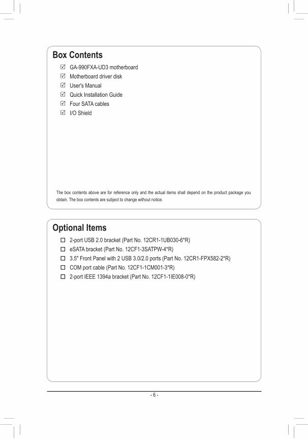
Box Contents 5 GA-990FXA-UD3 motherboard 5 Motherboard driver disk 5 User's Manual 5 Quick Installation Guide 5 Four SATA cables 5 I/O Shield
Optional Items � 2-portUSB2.0bracket(PartNo.12CR1-1UB030-6*R) � eSATAbracket(PartNo.12CF1-3SATPW-4*R) � 3.5"FrontPanelwith2USB3.0/2.0ports(PartNo.12CR1-FPX582-2*R) � COMportcable(PartNo.12CF1-1CM001-3*R) � 2-portIEEE1394abracket(PartNo.12CF1-1IE008-0*R)
The box contents above are for reference only and the actual items shall depend on the product package you obtain. The box contents are subject to change without notice.

- 7 -
GA-990FXA-UD3 Motherboard Layout
KB_MS_USB CPU_FAN
Socket AM3+
ATX
GA-990FXA-UD3
AUDIO
DDR3
_4
DDR3
_2
BAT
ATX_12V
AMD 990FX
R_USB30
CODEC
PWR_FAN
OPTICAL
USB_1394_ESATA
USB_ESATA
USB_LAN
M_BIOS
B_BIOS
CLR_CMOS
Realtek® GbE LAN
iTE®
Super I/O
DDR3
_3
DDR3
_1
F_USB2 F_USB30 TPM F_PANELF_USB1F_USB3SYS_FAN2
SPDIF_O
F_AUDIO COMA
AMD SB950
SYS_FAN1
VIA®
VT6308
PCIEX1_1 (Note)
PCIEX16_1
PCIEX1_2
PCIEX4_1
PCIEX16_2
PCI
PCIEX4_2
Marvell®88SE9172
SATA3
4 52 30 1
F_1394
VIA® VL805
(Note) Duetoahardwarelimitation,thePCIEX1_1slotcanonlyaccommodateashorterPCIExpressx1expansion card. For a longer expansion card, use other expansion slots.
- 8 -
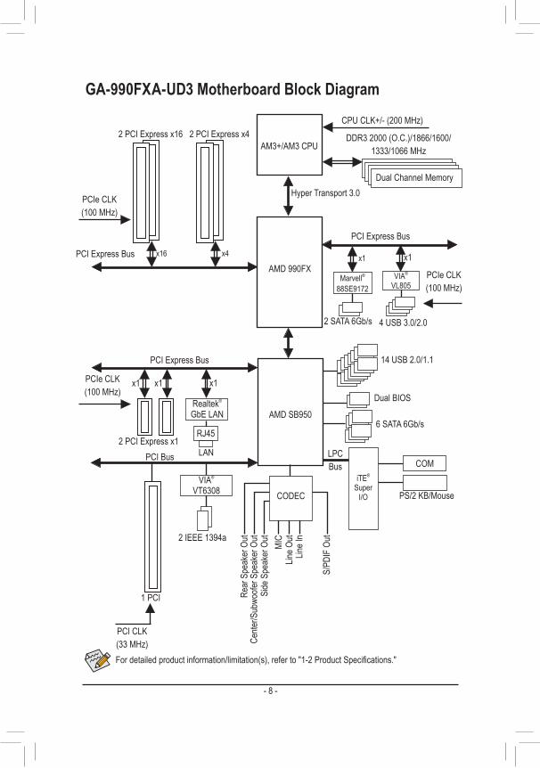
GA-990FXA-UD3 Motherboard Block Diagram
Fordetailedproductinformation/limitation(s),referto"1-2ProductSpecifications."
AM3+/AM3 CPU
Hyper Transport 3.0
AMD 990FX
CPUCLK+/-(200MHz)
DDR32000(O.C.)/1866/1600/ 1333/1066MHz
Dual Channel Memory
AMD SB950
iTE® Super
I/O
COM LPC Bus
6 SATA 6Gb/s
Cente
r/Sub
woofe
r Spe
aker
Out
Line O
utMI
C
Line I
n
S/PD
IF O
ut
Side
Spe
aker
Out
Rear
Spe
aker
Out
CODEC
1 PCI
PCI Bus
PCI CLK(33MHz)
VIA®
VT6308
2 IEEE 1394a
Dual BIOS
PCIe CLK(100MHz)
PCI Express Bus
LAN
RJ45
x1
PS/2 KB/Mouse
Realtek®
GbE LAN
14 USB 2.0/1.1
PCI Express Bus
PCIe CLK(100MHz)
2 PCI Express x16
x16 x1
Marvell® 88SE9172
2 SATA 6Gb/s
2 PCI Express x4
x4
PCI Express Bus
PCIe CLK(100MHz)
2 PCI Express x1
x1
4 USB 3.0/2.0
x1
VIA® VL805
x1

- 9 - Hardware Installation
Chapter 1 Hardware Installation1-1 Installation PrecautionsThe motherboard contains numerous delicate electronic circuits and components which can become damaged as a result of electrostatic discharge (ESD). Prior to installation, carefully read the user's manual and follow these procedures:
• Prior to installation, make sure the chassis is suitable for the motherboard. • Prior to installation, do not remove or break motherboard S/N (Serial Number) sticker or
warranty sticker provided by your dealer. These stickers are required for warranty validation. • Always remove the AC power by unplugging the power cord from the power outlet before
installing or removing the motherboard or other hardware components. • When connecting hardware components to the internal connectors on the motherboard, make
sure they are connected tightly and securely. • When handling the motherboard, avoid touching any metal leads or connectors. • It is best to wear an electrostatic discharge (ESD) wrist strap when handling electronic com-
ponents such as a motherboard, CPU or memory. If you do not have an ESD wrist strap, keep your hands dry and first touch a metal object to eliminate static electricity.
• Prior to installing the motherboard, please have it on top of an antistatic pad or within an electrostatic shielding container.
• Before unplugging the power supply cable from the motherboard, make sure the power supply has been turned off.
• Before turning on the power, make sure the power supply voltage has been set according to the local voltage standard.
• Before using the product, please verify that all cables and power connectors of your hardware components are connected.
• To prevent damage to the motherboard, do not allow screws to come in contact with the motherboard circuit or its components.
• Make sure there are no leftover screws or metal components placed on the motherboard or within the computer casing.
• Do not place the computer system on an uneven surface. • Do not place the computer system in a high-temperature environment. • Turning on the computer power during the installation process can lead to damage to system
components as well as physical harm to the user. • If you are uncertain about any installation steps or have a problem related to the use of the
product, please consult a certified computer technician.
Hardware Installation - 10 -
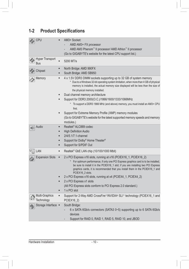
1-2 ProductSpecificationsCPU � AM3+ Socket:
- AMD AM3+ FX processor - AMD AM3 Phenom™ II processor/ AMD Athlon™ II processor
(Go to GIGABYTE's website for the latest CPU support list.)Hyper Transport Bus � 5200 MT/s
Chipset � North Bridge: AMD 990FX � South Bridge: AMD SB950
Memory � 4 x 1.5V DDR3 DIMM sockets supporting up to 32 GB of system memory * Due to a Windows 32-bit operating system limitation, when more than 4 GB of physical
memory is installed, the actual memory size displayed will be less than the size of the physical memory installed.
� Dual channel memory architecture � Support for DDR3 2000(O.C.)/1866/1600/1333/1066MHz
* To support a DDR3 1866 MHz (and above) memory, you must install an AM3+ CPU first.
� Support for Extreme Memory Profile (XMP) memory modules (Go to GIGABYTE's website for the latest supported memory speeds and memory
modules.)Audio � Realtek® ALC889 codec
� High Definition Audio � 2/4/5.1/7.1-channel � Support for Dolby® Home Theater®
� Support for S/PDIF Out
LAN � Realtek® GbE LAN chip (10/100/1000 Mbit)
Expansion Slots � 2 x PCI Express x16 slots, running at x16 (PCIEX16_1, PCIEX16_2) * For optimum performance, if only one PCI Express graphics card is to be installed,
be sure to install it in the PCIEX16_1 slot; if you are installing two PCI Express graphics cards, it is recommended that you install them in the PCIEX16_1 and PCIEX16_2 slots.
� 2 x PCI Express x16 slots, running at x4 (PCIEX4_1, PCIEX4_2) � 2 x PCI Express x1 slots
(All PCI Express slots conform to PCI Express 2.0 standard.) � 1 x PCI slot
Multi-Graphics Technology
� Support for 2-Way AMD CrossFire™/NVIDIA® SLI™ technology (PCIEX16_1 and PCIEX16_2)
Storage Interface � South Bridge: - 6 x SATA 6Gb/s connectors (SATA3 0~5) supporting up to 6 SATA 6Gb/s
devices - Support for RAID 0, RAID 1, RAID 5, RAID 10, and JBOD
- 11 - Hardware Installation
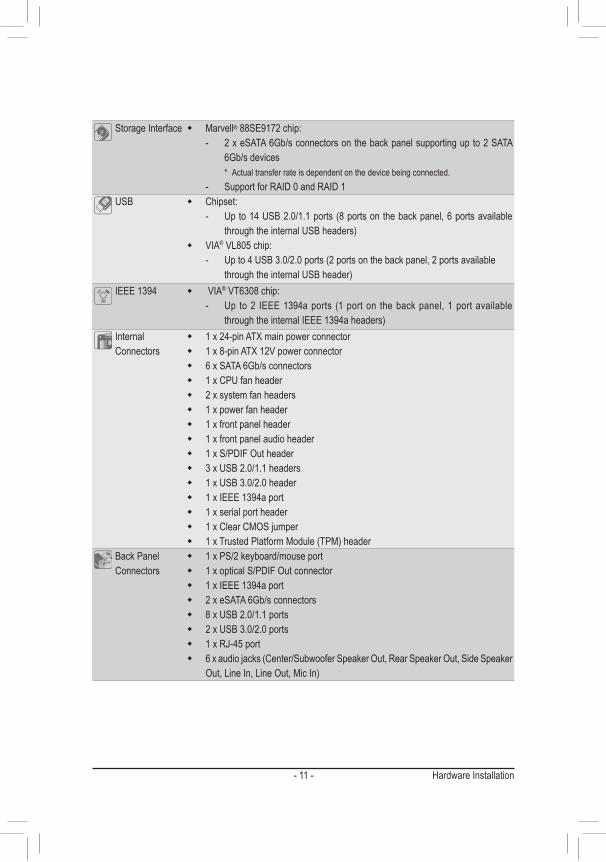
Storage Interface � Marvell® 88SE9172 chip: - 2 x eSATA 6Gb/s connectors on the back panel supporting up to 2 SATA
6Gb/s devices* Actual transfer rate is dependent on the device being connected.
- Support for RAID 0 and RAID 1USB � Chipset:
- Up to 14 USB 2.0/1.1 ports (8 ports on the back panel, 6 ports available through the internal USB headers)
� VIA® VL805 chip:- Up to 4 USB 3.0/2.0 ports (2 ports on the back panel, 2 ports available
through the internal USB header)IEEE 1394 � VIA® VT6308 chip:
- Up to 2 IEEE 1394a ports (1 port on the back panel, 1 port available through the internal IEEE 1394a headers)
Internal Connectors
� 1 x 24-pin ATX main power connector � 1 x 8-pin ATX 12V power connector � 6 x SATA 6Gb/s connectors � 1 x CPU fan header � 2 x system fan headers � 1 x power fan header � 1 x front panel header � 1 x front panel audio header � 1 x S/PDIF Out header � 3 x USB 2.0/1.1 headers � 1 x USB 3.0/2.0 header � 1 x IEEE 1394a port � 1 x serial port header � 1 x Clear CMOS jumper � 1 x Trusted Platform Module (TPM) header
Back Panel Connectors
� 1 x PS/2 keyboard/mouse port � 1 x optical S/PDIF Out connector � 1 x IEEE 1394a port � 2 x eSATA 6Gb/s connectors � 8 x USB 2.0/1.1 ports � 2 x USB 3.0/2.0 ports � 1 x RJ-45 port � 6 x audio jacks (Center/Subwoofer Speaker Out, Rear Speaker Out, Side Speaker
Out, Line In, Line Out, Mic In)
Hardware Installation - 12 -
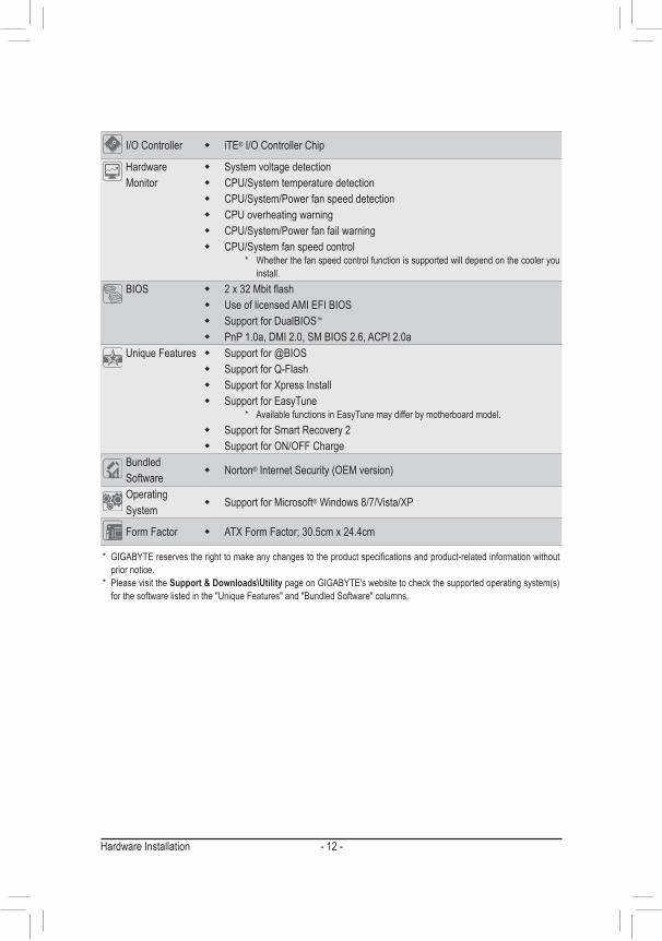
I/O Controller � iTE® I/O Controller Chip
Hardware Monitor
� System voltage detection � CPU/System temperature detection � CPU/System/Power fan speed detection � CPU overheating warning � CPU/System/Power fan fail warning � CPU/System fan speed control
* Whether the fan speed control function is supported will depend on the cooler you install.
BIOS � 2 x 32 Mbit flash � Use of licensed AMI EFI BIOS � Support for DualBIOS™
� PnP 1.0a, DMI 2.0, SM BIOS 2.6, ACPI 2.0aUnique Features � Support for @BIOS
� Support for Q-Flash � Support for Xpress Install � Support for EasyTune
* Available functions in EasyTune may differ by motherboard model. � Support for Smart Recovery 2 � Support for ON/OFF Charge
Bundled Software � Norton® Internet Security (OEM version)
Operating System � Support for Microsoft® Windows 8/7/Vista/XP
Form Factor � ATX Form Factor; 30.5cm x 24.4cm
* GIGABYTE reserves the right to make any changes to the product specifications and product-related information without prior notice.
* Please visit the Support & Downloads\Utility page on GIGABYTE's website to check the supported operating system(s) for the software listed in the "Unique Features" and "Bundled Software" columns.
- 13 - Hardware Installation
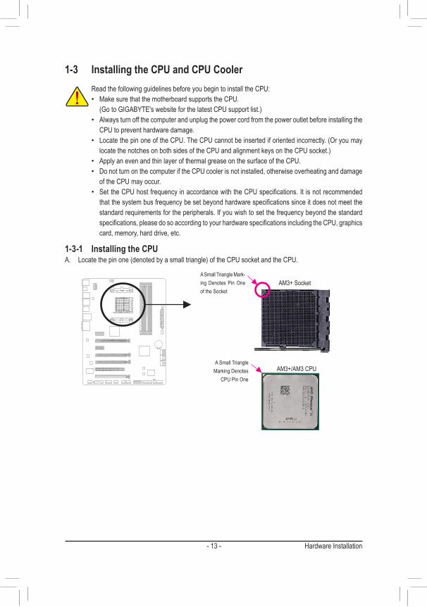
1-3 Installing the CPU and CPU Cooler
1-3-1 Installing the CPUA. Locate the pin one (denoted by a small triangle) of the CPU socket and the CPU.
Read the following guidelines before you begin to install the CPU:• Make sure that the motherboard supports the CPU. (Go to GIGABYTE's website for the latest CPU support list.)• Always turn off the computer and unplug the power cord from the power outlet before installing the
CPU to prevent hardware damage.• Locate the pin one of the CPU. The CPU cannot be inserted if oriented incorrectly. (Or you may
locate the notches on both sides of the CPU and alignment keys on the CPU socket.)• Apply an even and thin layer of thermal grease on the surface of the CPU.• Do not turn on the computer if the CPU cooler is not installed, otherwise overheating and damage
of the CPU may occur.• Set the CPU host frequency in accordance with the CPU specifications. It is not recommended
that the system bus frequency be set beyond hardware specifications since it does not meet the standard requirements for the peripherals. If you wish to set the frequency beyond the standard specifications, please do so according to your hardware specifications including the CPU, graphics card, memory, hard drive, etc.
AM3+/AM3 CPU
AM3+ Socket
A Small Triangle Marking Denotes
CPU Pin One
A Small Triangle Mark-ing Denotes Pin One of the Socket

Hardware Installation - 14 -
B. Follow the steps below to correctly install the CPU into the motherboard CPU socket.
• Before installing the CPU, make sure to turn off the computer and unplug the power cord from the power outlet to prevent damage to the CPU.
• Do not force the CPU into the CPU socket. The CPU cannot fit in if oriented incorrectly. Adjust the CPU orientation if this occurs.
Step 1:Completely lift up the CPU socket locking lever.
Step 2:Align the CPU pin one (small triangle marking) with the triangle mark on the CPU socket and gently insert the CPU into the socket. Make sure that the CPU pins fit perfectly into their holes.Once the CPU is positioned into its socket, place one finger down on the middle of the CPU, lowering the locking lever and latching it into the fully locked position.
CPU Socket Locking Lever
- 15 - Hardware Installation
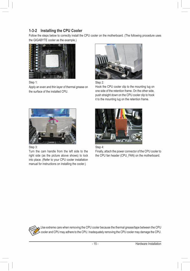
Use extreme care when removing the CPU cooler because the thermal grease/tape between the CPU cooler and CPU may adhere to the CPU. Inadequately removing the CPU cooler may damage the CPU.
1-3-2 Installing the CPU CoolerFollow the steps below to correctly install the CPU cooler on the motherboard. (The following procedure uses the GIGABYTE cooler as the example.)
Step 1:Apply an even and thin layer of thermal grease on the surface of the installed CPU.
Step 2:Hook the CPU cooler clip to the mounting lug on one side of the retention frame. On the other side, push straight down on the CPU cooler clip to hook it to the mounting lug on the retention frame.
Step 3:Turn the cam handle from the left side to the right side (as the picture above shows) to lock into place. (Refer to your CPU cooler installation manual for instructions on installing the cooler.)
Step 4:Finally, attach the power connector of the CPU cooler to the CPU fan header (CPU_FAN) on the motherboard.
Hardware Installation - 16 -
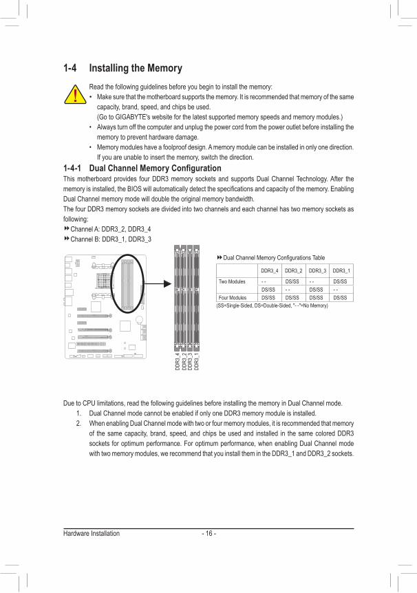
1-4 Installing the Memory
Due to CPU limitations, read the following guidelines before installing the memory in Dual Channel mode.1. Dual Channel mode cannot be enabled if only one DDR3 memory module is installed.2. When enabling Dual Channel mode with two or four memory modules, it is recommended that memory
of the same capacity, brand, speed, and chips be used and installed in the same colored DDR3 sockets for optimum performance. For optimum performance, when enabling Dual Channel mode with two memory modules, we recommend that you install them in the DDR3_1 and DDR3_2 sockets.
Read the following guidelines before you begin to install the memory:• Make sure that the motherboard supports the memory. It is recommended that memory of the same
capacity, brand, speed, and chips be used. (Go to GIGABYTE's website for the latest supported memory speeds and memory modules.)• Always turn off the computer and unplug the power cord from the power outlet before installing the
memory to prevent hardware damage.• Memory modules have a foolproof design. A memory module can be installed in only one direction.
If you are unable to insert the memory, switch the direction.
DDR3
_4DD
R3_2
DDR3
_3DD
R3_1
1-4-1 DualChannelMemoryConfigurationThis motherboard provides four DDR3 memory sockets and supports Dual Channel Technology. After the memory is installed, the BIOS will automatically detect the specifications and capacity of the memory. Enabling Dual Channel memory mode will double the original memory bandwidth.The four DDR3 memory sockets are divided into two channels and each channel has two memory sockets as following:
Channel A: DDR3_2, DDR3_4Channel B: DDR3_1, DDR3_3
Dual Channel Memory Configurations Table
(SS=Single-Sided, DS=Double-Sided, "- -"=No Memory)
DDR3_4 DDR3_2 DDR3_3 DDR3_1
Two Modules - - DS/SS - - DS/SSDS/SS - - DS/SS - -
Four Modules DS/SS DS/SS DS/SS DS/SS
- 17 - Hardware Installation
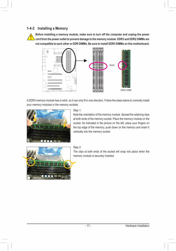
1-4-2 Installing a MemoryBefore installing a memory module, make sure to turn off the computer and unplug the power cord from the power outlet to prevent damage to the memory module. DDR3 and DDR2 DIMMs are not compatible to each other or DDR DIMMs. Be sure to install DDR3 DIMMs on this motherboard.
A DDR3 memory module has a notch, so it can only fit in one direction. Follow the steps below to correctly install your memory modules in the memory sockets.
Notch
DDR3 DIMM
Step 1:Note the orientation of the memory module. Spread the retaining clips at both ends of the memory socket. Place the memory module on the socket. As indicated in the picture on the left, place your fingers on the top edge of the memory, push down on the memory and insert it vertically into the memory socket.
Step 2:The clips at both ends of the socket will snap into place when the memory module is securely inserted.

Hardware Installation - 18 -
1-5 Installing an Expansion CardRead the following guidelines before you begin to install an expansion card:• Make sure the motherboard supports the expansion card. Carefully read the manual that came
with your expansion card.• Always turn off the computer and unplug the power cord from the power outlet before installing an
expansion card to prevent hardware damage.
Follow the steps below to correctly install your expansion card in the expansion slot.1. Locate an expansion slot that supports your card. Remove the metal slot cover from the chassis back panel.2. Align the card with the slot, and press down on the card until it is fully seated in the slot.3. Make sure the metal contacts on the card are completely inserted into the slot.4. Secure the card’s metal bracket to the chassis back panel with a screw.5. After installing all expansion cards, replace the chassis cover(s).6. Turn on your computer. If necessary, go to BIOS Setup to make any required BIOS changes for your expan-
sion card(s).7. Install the driver provided with the expansion card in your operating system.
Example: Installing and Removing a PCI Express Graphics Card:
PCI Slot
PCI Express x1 Slot
PCI Express x16 Slot
• Installing a Graphics Card:Gently push down on the top edge of the card until it is fully inserted into the PCI Express slot. Make sure the card is securely seated in the slot and does not rock.
• Removing the Card:Gently push back on the lever on the slot and then lift the card straight out from the slot.
- 19 - Hardware Installation
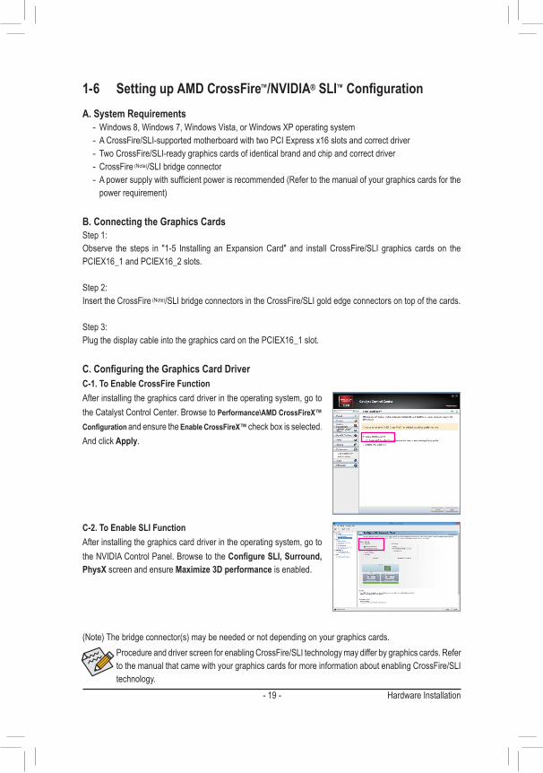
1-6 Setting up AMD CrossFire™/NVIDIA® SLI™ConfigurationA. System Requirements
- Windows 8, Windows 7, Windows Vista, or Windows XP operating system - A CrossFire/SLI-supported motherboard with two PCI Express x16 slots and correct driver - Two CrossFire/SLI-ready graphics cards of identical brand and chip and correct driver - CrossFire (Note)/SLI bridge connector - A power supply with sufficient power is recommended (Refer to the manual of your graphics cards for the power requirement)
B. Connecting the Graphics CardsStep 1:Observe the steps in "1-5 Installing an Expansion Card" and install CrossFire/SLI graphics cards on the PCIEX16_1 and PCIEX16_2 slots.
Step 2:Insert the CrossFire (Note)/SLI bridge connectors in the CrossFire/SLI gold edge connectors on top of the cards.
Step 3:Plug the display cable into the graphics card on the PCIEX16_1 slot.
C.ConfiguringtheGraphicsCardDriverC-1. To Enable CrossFire FunctionAfter installing the graphics card driver in the operating system, go to the Catalyst Control Center. Browse to Performance\AMD CrossFireX™ Configuration and ensure the Enable CrossFireX™ check box is selected. And click Apply.
(Note) The bridge connector(s) may be needed or not depending on your graphics cards.Procedure and driver screen for enabling CrossFire/SLI technology may differ by graphics cards. Refer to the manual that came with your graphics cards for more information about enabling CrossFire/SLI technology.
C-2. To Enable SLI FunctionAfter installing the graphics card driver in the operating system, go to the NVIDIA Control Panel. Browse to the ConfigureSLI,Surround,PhysX screen and ensure Maximize 3D performance is enabled.

Hardware Installation - 20 -
1-7 Back Panel Connectors
USB 2.0/1.1 PortThe USB port supports the USB 2.0/1.1 specification. Use this port for USB devices such as a USB keyboard/mouse, USB printer, USB flash drive and etc.PS/2 Keyboard/Mouse PortUse this port to connect a PS/2 mouse or keyboard.Optical S/PDIF Out ConnectorThis connector provides digital audio out to an external audio system that supports digital optical audio. Before using this feature, ensure that your audio system provides an optical digital audio in connector.IEEE 1394a Port The IEEE 1394 port supports the IEEE 1394a specification, featuring high speed, high bandwidth and hotplug capabilities. Use this port for an IEEE 1394a device.eSATA 6Gb/s ConnectorThe eSATA 6Gb/s port conforms to SATA 6Gb/s standard and is compatible with SATA 3Gb/s and SATA 1.5Gb/s standards. Use the port to connect an external SATA device or a SATA port multiplier. The Marvell® 88SE9172 chip supports RAID function. Refer to Chapter 3, "Configuring SATA Hard Drive(s)," for instructions on configuring a RAID array.USB 3.0/2.0 PortThe USB 3.0 port supports the USB 3.0 specification and is compatible to the USB 2.0/1.1 specification. Use this port for USB devices such as a USB keyboard/mouse, USB printer, USB flash drive and etc.RJ-45 LAN PortThe Gigabit Ethernet LAN port provides Internet connection at up to 1 Gbps data rate. The following describes the states of the LAN port LEDs.
Activity LED:State DescriptionBlinking Data transmission or receiving is occurringOff No data transmission or receiving is occurring
Connection/Speed LED:State DescriptionOrange 1 Gbps data rateGreen 100 Mbps data rateOff 10 Mbps data rate
Activity LEDConnection/Speed LED
LAN Port
- 21 - Hardware Installation
The audio jacks can be reconfigured to perform different functions via the audio software (supported functions for each jack may vary based on hardware specification). Only microphones still MUST be connected to the default Mic in jack. Refer to the instructions on setting up a 2/4/5.1/7.1-channel audio configuration in Chapter 6, "Configuring 2/4/5.1/7.1-Channel Audio."
Center/Subwoofer Speaker Out Jack (Orange)Use this audio jack to connect center/subwoofer speakers in a 5.1/7.1-channel audio configuration.Rear Speaker Out Jack (Black)Use this audio jack to connect rear speakers in a 7.1-channel audio configuration.Side Speaker Out Jack (Gray)Use this audio jack to connect side speakers in a 4/5.1/7.1-channel audio configuration.Line In Jack (Blue)The default line in jack. Use this audio jack for line in devices such as an optical drive, walkman, etc.Line Out Jack (Green)The default line out jack. Use this audio jack for a headphone or 2-channel speaker. This jack can be used to connect front speakers in a 4/5.1/7.1-channel audio configuration.Mic In Jack (Pink)The default Mic in jack. Microphones must be connected to this jack.
• When removing the cable connected to a back panel connector, first remove the cable from your device and then remove it from the motherboard.
• When removing the cable, pull it straight out from the connector. Do not rock it side to side to prevent an electrical short inside the cable connector.
Hardware Installation - 22 -
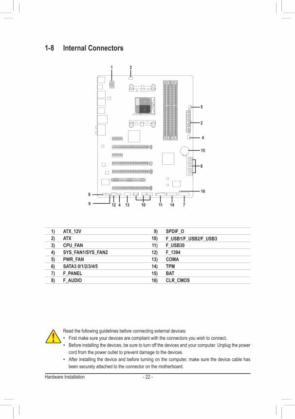
1-8 Internal Connectors
1 3
8
4 10 11
6
4
2
5
71412 139
16
15
1) ATX_12V2) ATX3) CPU_FAN4) SYS_FAN1/SYS_FAN25) PWR_FAN6) SATA3 0/1/2/3/4/57) F_PANEL8) F_AUDIO
9) SPDIF_O10) F_USB1/F_USB2/F_USB311) F_USB3012) F_139413) COMA14) TPM15) BAT16) CLR_CMOS
Read the following guidelines before connecting external devices: • First make sure your devices are compliant with the connectors you wish to connect. • Before installing the devices, be sure to turn off the devices and your computer. Unplug the power
cord from the power outlet to prevent damage to the devices. • After installing the device and before turning on the computer, make sure the device cable has
been securely attached to the connector on the motherboard.
- 23 - Hardware Installation
DEBUG PORT
131
2412
ATX
DEBUG PORT
ATX_12V
5
8
1
4ATX_12V:
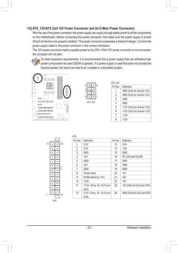
Pin No. Definition1 GND (Only for 2x4-pin 12V)2 GND (Only for 2x4-pin 12V)3 GND4 GND5 +12V (Only for 2x4-pin 12V)6 +12V (Only for 2x4-pin 12V)7 +12V8 +12V
ATX:
Pin No. Definition Pin No. Definition1 3.3V 13 3.3V2 3.3V 14 -12V3 GND 15 GND4 +5V 16 PS_ON (soft On/Off)5 GND 17 GND6 +5V 18 GND7 GND 19 GND8 Power Good 20 -5V9 5VSB (stand by +5V) 21 +5V
10 +12V 22 +5V11 +12V (Only for 2x12-pin
ATX)23 +5V (Only for 2x12-pin ATX)
12 3.3V (Only for 2x12-pin ATX)
24 GND (Only for 2x12-pin ATX)
1/2) ATX_12V/ATX (2x4 12V Power Connector and 2x12 Main Power Connector) With the use of the power connector, the power supply can supply enough stable power to all the components
on the motherboard. Before connecting the power connector, first make sure the power supply is turned off and all devices are properly installed. The power connector possesses a foolproof design. Connect the power supply cable to the power connector in the correct orientation.
The 12V power connector mainly supplies power to the CPU. If the 12V power connector is not connected, the computer will not start.
To meet expansion requirements, it is recommended that a power supply that can withstand high power consumption be used (500W or greater). If a power supply is used that does not provide the required power, the result can lead to an unstable or unbootable system.
Hardware Installation - 24 -
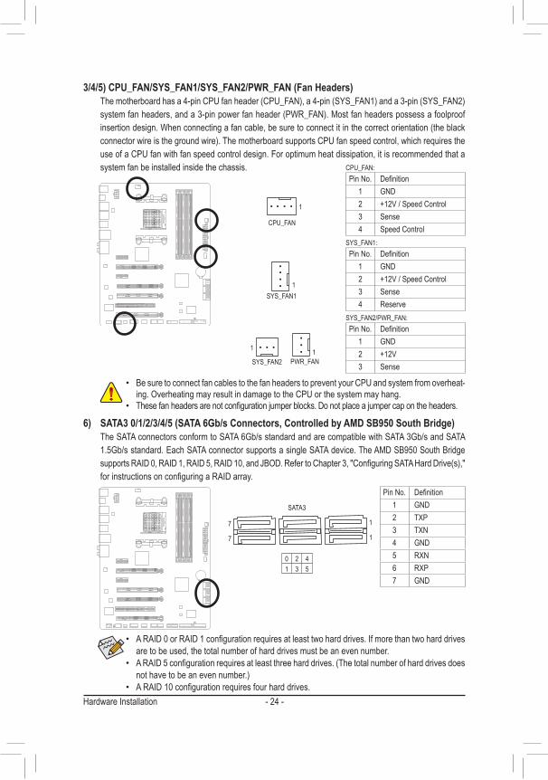
3/4/5) CPU_FAN/SYS_FAN1/SYS_FAN2/PWR_FAN (Fan Headers) The motherboard has a 4-pin CPU fan header (CPU_FAN), a 4-pin (SYS_FAN1) and a 3-pin (SYS_FAN2)
system fan headers, and a 3-pin power fan header (PWR_FAN). Most fan headers possess a foolproof insertion design. When connecting a fan cable, be sure to connect it in the correct orientation (the black connector wire is the ground wire). The motherboard supports CPU fan speed control, which requires the use of a CPU fan with fan speed control design. For optimum heat dissipation, it is recommended that a system fan be installed inside the chassis.
• Be sure to connect fan cables to the fan headers to prevent your CPU and system from overheat-ing. Overheating may result in damage to the CPU or the system may hang.
• These fan headers are not configuration jumper blocks. Do not place a jumper cap on the headers.
CPU_FAN:Pin No. Definition
1 GND2 +12V / Speed Control3 Sense4 Speed Control
SYS_FAN1:
SYS_FAN2/PWR_FAN:
Pin No. Definition1 GND2 +12V / Speed Control3 Sense4 Reserve
Pin No. Definition1 GND2 +12V3 Sense
1
CPU_FAN
SYS_FAN1
SYS_FAN2
DEBUG PORT
DEBUG PORT
1
1
1PWR_FAN
6) SATA3 0/1/2/3/4/5 (SATA 6Gb/s Connectors, Controlled by AMD SB950 South Bridge) The SATA connectors conform to SATA 6Gb/s standard and are compatible with SATA 3Gb/s and SATA
1.5Gb/s standard. Each SATA connector supports a single SATA device. The AMD SB950 South Bridge supports RAID 0, RAID 1, RAID 5, RAID 10, and JBOD. Refer to Chapter 3, "Configuring SATA Hard Drive(s)," for instructions on configuring a RAID array.
1
1
7
7
DEBUG PORT
DEBUG PORT
DEBUG PORT
• A RAID 0 or RAID 1 configuration requires at least two hard drives. If more than two hard drives are to be used, the total number of hard drives must be an even number.
• A RAID 5 configuration requires at least three hard drives. (The total number of hard drives does not have to be an even number.)
• A RAID 10 configuration requires four hard drives.
Pin No. Definition1 GND2 TXP3 TXN4 GND5 RXN6 RXP7 GND
0 2 41 3 5
SATA3

- 25 - Hardware Installation
The front panel design may differ by chassis. A front panel module mainly consists of power switch, reset switch, power LED, hard drive activity LED, speaker and etc. When connecting your chassis front panel module to this header, make sure the wire assignments and the pin assignments are matched correctly.
7) F_PANEL (Front Panel Header) Connect the power switch, reset switch, speaker, chassis intrusion switch/sensor and system status indicator
on the chassis to this header according to the pin assignments below. Note the positive and negative pins before connecting the cables.
Power LED
DEBUG PORT
12
1920
CI- CI
+
PWR_
LED+
PLED
-
PW-
SPEA
K+
SPEA
K-
PLED
+
PW+
HD-
RES+
HD+
RES-
Hard Drive Activity LED
Reset Switch Chassis Intru-
sion Header
Power Switch Speaker
PWR_
LED-
PWR_
LED-
Power LED
System Status LEDS0 OnS3/S4/S5 Off
• PW (Power Switch, Red): Connects to the power switch on the chassis front panel. You may configure the way to turn off your
system using the power switch (refer to Chapter 2, "BIOS Setup," "Power Management," for more information).
• SPEAK (Speaker, Orange): Connects to the speaker on the chassis front panel. The system reports system startup status by issuing
a beep code. One single short beep will be heard if no problem is detected at system startup. • HD (Hard Drive Activity LED, Blue):
Connects to the hard drive activity LED on the chassis front panel. The LED is on when the hard drive is reading or writing data.
• RES (Reset Switch, Green): Connects to the reset switch on the chassis front panel. Press the reset switch to restart the computer
if the computer freezes and fails to perform a normal restart. • CI (Chassis Intrusion Header, Gray):
Connects to the chassis intrusion switch/sensor on the chassis that can detect if the chassis cover has been removed. This function requires a chassis with a chassis intrusion switch/sensor.
• PLED/PWR_LED (Power LED, Yellow/Purple):Connects to the power status indicator on the chassis front panel. The LED is on when the system is operating. The LED is off when the system is in S3/S4 sleep state or powered off (S5).

Hardware Installation - 26 -
8) F_AUDIO (Front Panel Audio Header) The front panel audio header supports Intel High Definition audio (HD) and AC'97 audio. You may connect
your chassis front panel audio module to this header. Make sure the wire assignments of the module con-nector match the pin assignments of the motherboard header. Incorrect connection between the module connector and the motherboard header will make the device unable to work or even damage it.
• The front panel audio header supports HD audio by default. If your chassis provides an AC'97 front panel audio module, refer to the instructions on how to activate AC'97 functionality via the audio software in Chapter 6, "Configuring 2/4/5.1/7.1-Channel Audio."
• Audio signals will be present on both of the front and back panel audio connections simultane-ously. If you want to mute the back panel audio (only supported when using an HD front panel audio module), refer to Chapter 6, "Configuring 2/4/5.1/7.1-Channel Audio."
• Some chassis provide a front panel audio module that has separated connectors on each wire instead of a single plug. For information about connecting the front panel audio module that has different wire assignments, please contact the chassis manufacturer.
For HD Front Panel Audio: For AC'97 Front Panel Audio:Pin No. Definition
1 MIC2 GND3 MIC Power4 NC5 Line Out (R)6 NC7 NC8 No Pin9 Line Out (L)
10 NC
9) SPDIF_O (S/PDIF Out Header) This header supports digital S/PDIF Out and connects a S/PDIF digital audio cable (provided by expansion
cards) for digital audio output from your motherboard to certain expansion cards like graphics cards and sound cards. For example, some graphics cards may require you to use a S/PDIF digital audio cable for digital audio output from your motherboard to your graphics card if you wish to connect an HDMI display to the graphics card and have digital audio output from the HDMI display at the same time. For information about connecting the S/PDIF digital audio cable, carefully read the manual for your expansion card.
1
Pin No. Definition1 SPDIFO2 GND
F_USB30 F_AUDIO(H)
DB_PORT
F_PANEL(NH) F_PANEL(H61M-D2)
TPMw/housing
Voltage measurement module(X58A-OC)
PCIe power connector (SATA)(X58A-OC)
DIP
123
DIP
123
DIP
123
DIP
1 2 3
1
1
1
1
BIOS Switcher (X58A-OC)
PWM Switch (X58A-OC)
9 1
10 2
Pin No. Definition1 MIC2_L2 GND3 MIC2_R4 -ACZ_DET5 LINE2_R6 GND7 FAUDIO_JD8 No Pin9 LINE2_L
10 GND

- 27 - Hardware Installation
10) F_USB1/F_USB2/F_USB3 (USB 2.0/1.1 Headers) The headers conform to USB 2.0/1.1 specification. Each USB header can provide two USB ports via an
optional USB bracket. For purchasing the optional USB bracket, please contact the local dealer.DEBUG PORT
109
21
Pin No. Definition1 Power (5V)2 Power (5V)3 USB DX-4 USB DY-5 USB DX+6 USB DY+7 GND8 GND9 No Pin
10 NC
• Do not plug the IEEE 1394 bracket (2x5-pin) cable into the USB header. • Prior to installing the USB bracket, be sure to turn off your computer and unplug the power cord
from the power outlet to prevent damage to the USB bracket.
11) F_USB30 (USB 3.0/2.0 Header) The header conforms to USB 3.0/2.0 specification and can provide two USB ports. For purchasing the
optional 3.5" front panel that provides two USB 3.0/2.0 ports, please contact the local dealer.
F_USB30 F_AUDIO(H)
DB_PORT
F_PANEL(NH) F_PANEL(H61M-D2)
TPMw/housing
Voltage measurement module(X58A-OC)
PCIe power connector (SATA)(X58A-OC)
DIP
123
DIP
123
DIP
123
DIP
1 2 3
1
1
1
1
BIOS Switcher (X58A-OC)
PWM Switch (X58A-OC)
10
1120
1
Pin No. Definition Pin No. Definition1 VBUS 11 D2+2 SSRX1- 12 D2-3 SSRX1+ 13 GND4 GND 14 SSTX2+5 SSTX1- 15 SSTX2-6 SSTX1+ 16 GND7 GND 17 SSRX2+8 D1- 18 SSRX2-9 D1+ 19 VBUS
10 NC 20 No Pin
Hardware Installation - 28 -
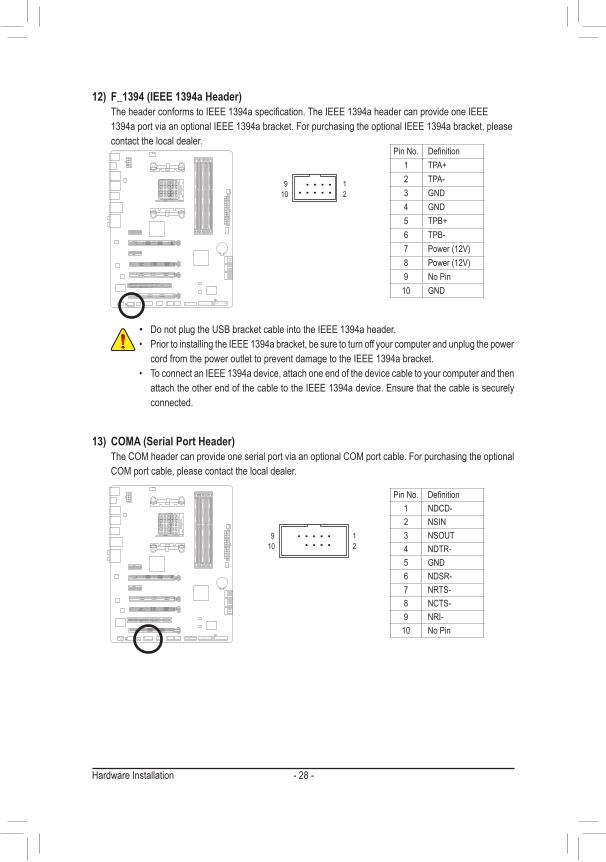
12) F_1394 (IEEE 1394a Header) The header conforms to IEEE 1394a specification. The IEEE 1394a header can provide one IEEE
1394a port via an optional IEEE 1394a bracket. For purchasing the optional IEEE 1394a bracket, please contact the local dealer.
DEBUG PORT
109
21
• Do not plug the USB bracket cable into the IEEE 1394a header.• Prior to installing the IEEE 1394a bracket, be sure to turn off your computer and unplug the power
cord from the power outlet to prevent damage to the IEEE 1394a bracket.• To connect an IEEE 1394a device, attach one end of the device cable to your computer and then
attach the other end of the cable to the IEEE 1394a device. Ensure that the cable is securely connected.
Pin No. Definition1 TPA+2 TPA-3 GND4 GND5 TPB+6 TPB-7 Power (12V)8 Power (12V)9 No Pin
10 GND
109
21
13) COMA (Serial Port Header) The COM header can provide one serial port via an optional COM port cable. For purchasing the optional
COM port cable, please contact the local dealer.
Pin No. Definition1 NDCD-2 NSIN 3 NSOUT4 NDTR-5 GND6 NDSR-7 NRTS-8 NCTS-9 NRI-
10 No Pin
- 29 - Hardware Installation
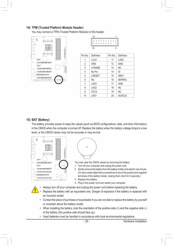
14) TPM (Trusted Platform Module Header) You may connect a TPM (Trusted Platform Module) to this header.
20
19
2
1
F_USB30 F_AUDIO(H)
DB_PORT
F_PANEL(NH) F_PANEL(H61M-D2)
TPMw/housing
Voltage measurement module(X58A-OC)
PCIe power connector (SATA)(X58A-OC)
DIP
123
DIP
123
DIP
123
DIP
1 2 3
1
1
1
1
BIOS Switcher (X58A-OC)
PWM Switch (X58A-OC)
Pin No. Definition Pin No. Definition1 LCLK 11 LAD02 GND 12 GND3 LFRAME 13 NC4 No Pin 14 ID5 LRESET 15 SB3V6 NC 16 SERIRQ7 LAD3 17 GND8 LAD2 18 NC9 VCC3 19 NC
10 LAD1 20 SUSCLK
15) BAT (Battery) The battery provides power to keep the values (such as BIOS configurations, date, and time information)
in the CMOS when the computer is turned off. Replace the battery when the battery voltage drops to a low level, or the CMOS values may not be accurate or may be lost.
You may clear the CMOS values by removing the battery:1. Turn off your computer and unplug the power cord.2. Gently remove the battery from the battery holder and wait for one minute.
(Or use a metal object like a screwdriver to touch the positive and negative terminals of the battery holder, making them short for 5 seconds.)
3. Replace the battery.4. Plug in the power cord and restart your computer.
• Always turn off your computer and unplug the power cord before replacing the battery.• Replace the battery with an equivalent one. Danger of explosion if the battery is replaced with
an incorrect model.• Contact the place of purchase or local dealer if you are not able to replace the battery by yourself
or uncertain about the battery model.• When installing the battery, note the orientation of the positive side (+) and the negative side (-)
of the battery (the positive side should face up).• Used batteries must be handled in accordance with local environmental regulations.
Hardware Installation - 30 -
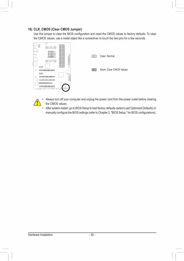
16) CLR_CMOS (Clear CMOS Jumper) Use this jumper to clear the BIOS configuration and reset the CMOS values to factory defaults. To clear
the CMOS values, use a metal object like a screwdriver to touch the two pins for a few seconds.
• Always turn off your computer and unplug the power cord from the power outlet before clearing the CMOS values.
• After system restart, go to BIOS Setup to load factory defaults (select Load Optimized Defaults) or manually configure the BIOS settings (refer to Chapter 2, "BIOS Setup," for BIOS configurations).
Open: Normal
Short: Clear CMOS Values

BIOS Setup- 31 -
BIOS (Basic Input and Output System) records hardware parameters of the system in the CMOS on the motherboard. Its major functions include conducting the Power-On Self-Test (POST) during system startup, saving system parameters and loading operating system, etc. BIOS includes a BIOS Setup program that allows the user to modify basic system configuration settings or to activate certain system features.
When the power is turned off, the battery on the motherboard supplies the necessary power to the CMOS to keep the configuration values in the CMOS.
To access the BIOS Setup program, press the <Delete> key during the POST when the power is turned on.
To upgrade the BIOS, use either the GIGABYTE Q-Flash or @BIOS utility. • Q-Flash allows the user to quickly and easily upgrade or back up BIOS without entering the operating system. • @BIOS is a Windows-based utility that searches and downloads the latest version of BIOS from the Internet
and updates the BIOS.For instructions on using the Q-Flash and @BIOS utilities, refer to Chapter 5, "BIOS Update Utilities."
Chapter 2 BIOS Setup
• Because BIOS flashing is potentially risky, if you do not encounter problems using the current version of BIOS, it is recommended that you not flash the BIOS. To flash the BIOS, do it with caution. Inadequate BIOS flashing may result in system malfunction.
• It is recommended that you not alter the default settings (unless you need to) to prevent system instability or other unexpected results. Inadequately altering the settings may result in system's failure to boot. If this occurs, try to clear the CMOS values and reset the board to default values. (Refer to the "Load Optimized Defaults" section in this chapter or introductions of the battery/clear CMOS jumper in Chapter 1 for how to clear the CMOS values.)
BIOS Setup - 32 -
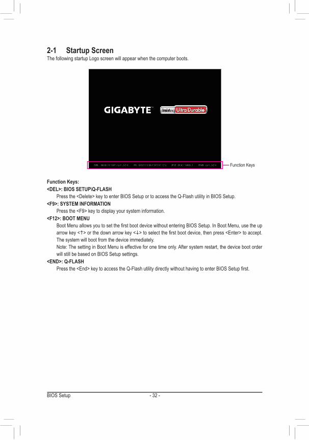
2-1 Startup ScreenThe following startup Logo screen will appear when the computer boots.
Function Keys:<DEL>: BIOS SETUP\Q-FLASH Press the <Delete> key to enter BIOS Setup or to access the Q-Flash utility in BIOS Setup.<F9>: SYSTEM INFORMATION Press the <F9> key to display your system information.<F12>: BOOT MENU Boot Menu allows you to set the first boot device without entering BIOS Setup. In Boot Menu, use the up
arrow key <h> or the down arrow key <i> to select the first boot device, then press <Enter> to accept. The system will boot from the device immediately.
Note: The setting in Boot Menu is effective for one time only. After system restart, the device boot order will still be based on BIOS Setup settings.
<END>: Q-FLASH Press the <End> key to access the Q-Flash utility directly without having to enter BIOS Setup first.
Function Keys

BIOS Setup- 33 -
2-2 The Main MenuOn the main menu of the BIOS Setup program, press arrow keys to move among the items and press <Enter> to accept or enter a sub-menu. Or you can use your mouse to select the item you want.(Sample BIOS Version: E14)
Setup Menus
Function Keys
Help
Enter Q-Flash
Configuration Items Current Settings
BIOS Setup Program Function Keys<f><g> Move the selection bar to select a setup menu<h><i> Move the selection bar to select an configuration item on a menu<Enter> Execute command or enter a menu<+>/<Page Up> Increase the numeric value or make changes<->/<Page Down> Decrease the numeric value or make changes<F5> Restore the previous BIOS settings for the current submenus<F7> Load the Optimized BIOS default settings for the current submenus<F8> Access the Q-Flash utility<F9> Display system information<F10> Save all the changes and exit the BIOS Setup program<F12> Capture the current screen as an image and save it to your USB drive<Esc> Main Menu: Exit the BIOS Setup program
Submenus: Exit current submenu

BIOS Setup - 34 -
BIOS Setup Menus � M.I.T.
Use this menu to configure the clock, frequency, and voltages of your CPU and memory, etc. Or check the system/CPU temperatures, voltages, and fan speeds.
� System Use this menu to configure the default language used by the BIOS and system time and date. This menu
also displays information on the devices connected to the SATA ports. � BIOS Features
Use this menu to configure the device boot order, advanced features available on the CPU, and the primary display adapter.
� Peripherals Use this menu to configure all peripheral devices, such as SATA, USB, integrated audio, and integrated
LAN, etc. � Power Management
Use this menu to configure all the power-saving functions. � Save & Exit
Save all the changes made in the BIOS Setup program to the CMOS and exit BIOS Setup. You can save the current BIOS settings to a profile or load optimized defaults for optimal-performance system operations.
• When the system is not stable as usual, select the Load Optimized Defaults item to set your system to its defaults.
• The BIOS Setup menus described in this chapter are for reference only and may differ by BIOS version.
BIOS Setup- 35 -
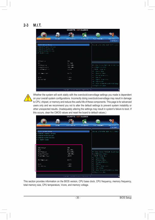
Whether the system will work stably with the overclock/overvoltage settings you made is dependent on your overall system configurations. Incorrectly doing overclock/overvoltage may result in damage to CPU, chipset, or memory and reduce the useful life of these components. This page is for advanced users only and we recommend you not to alter the default settings to prevent system instability or other unexpected results. (Inadequately altering the settings may result in system's failure to boot. If this occurs, clear the CMOS values and reset the board to default values.)
2-3 M.I.T.
This section provides information on the BIOS version, CPU base clock, CPU frequency, memory frequency, total memory size, CPU temperature, Vcore, and memory voltage.
BIOS Setup - 36 -
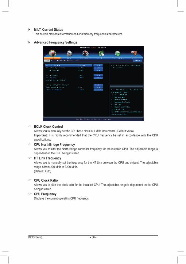
` M.I.T. Current Status This screen provides information on CPU/memory frequencies/parameters.
` Advanced Frequency Settings
& BCLK Clock Control Allows you to manually set the CPU base clock in 1 MHz increments. (Default: Auto) Important: It is highly recommended that the CPU frequency be set in accordance with the CPU
specifications. & CPU NorthBridge Frequency
Allows you to alter the North Bridge controller frequency for the installed CPU. The adjustable range is dependent on the CPU being installed.
& HT Link Frequency Allows you to manually set the frequency for the HT Link between the CPU and chipset. The adjustable
range is from 200 MHz to 3200 MHz. (Default: Auto)
& CPU Clock Ratio Allows you to alter the clock ratio for the installed CPU. The adjustable range is dependent on the CPU
being installed. & CPU Frequency
Displays the current operating CPU frequency.
BIOS Setup- 37 -
(Note) This item is present only when you install a CPU that supports this feature.
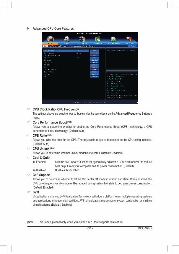
& CPU Clock Ratio, CPU Frequency The settings above are synchronous to those under the same items on the Advanced Frequency Settings
menu. & Core Performance Boost (Note)
Allows you to determine whether to enable the Core Performance Boost (CPB) technology, a CPU performance-boost technology. (Default: Auto)
& CPB Ratio (Note)
Allows you alter the ratio for the CPB. The adjustable range is dependent on the CPU being installed. (Default: Auto)
& CPU Unlock (Note)
Allows you to determine whether unlock hidden CPU cores. (Default: Disabled) & Cool & Quiet
�Enabled Lets the AMD Cool'n'Quiet driver dynamically adjust the CPU clock and VID to reduce heat output from your computer and its power consumption. (Default)
�Disabled Disables this function. & C1E Support
Allows you to determine whether to let the CPU enter C1 mode in system halt state. When enabled, the CPU core frequency and voltage will be reduced during system halt state to decrease power consumption. (Default: Enabled)
& SVM Virtualization enhanced by Virtualization Technology will allow a platform to run multiple operating systems
and applications in independent partitions. With virtualization, one computer system can function as multiple virtual systems. (Default: Enabled)
` Advanced CPU Core Features
BIOS Setup - 38 -
& CPU core Control (Note 1)
Allows you to determine whether to manually enable/disable CPU cores. Automatic mode allows the BIOS to enable all CPU cores (number of cores available depends on the CPU being used). (Default: Automatic mode)
& Core C6 State (Note 1)
Allows you to determine whether to let the CPU enter C6 mode in system halt state. When enabled, the CPU core frequency will be reduced during system halt state to decrease power consumption. The C6 state is a more enhanced power-saving state than C1. (Default: Enabled)
& HPC Mode (Note 1)
Allows you to determine whether to enable High Performance Computing (HPC) mode for the CPU. Enabled prevents the CPU frequency from being lowered during system halt state. (Default: Disabled)
& APM (AMD Application Power Management) (Note 1)
�Enabled Dynamically monitors the power consumption of the CPU cores and automatically optimizes the CPU to its best performance level. (Default)
�Disabled Disables this function.
& Extreme Memory Profile (X.M.P.) (Note 2)
Allows the BIOS to read the SPD data on XMP memory module(s) to enhance memory performance when enabled.
�Disabled Disables this function. (Default) �Profile1 Uses Profile 1 settings. �Profile2 (Note 2) Uses Profile 2 settings.
& System Memory Multiplier Allows you to set the system memory multiplier. Auto sets memory multiplier according to memory SPD
data. (Default: Auto) & Memory Frequency (MHz)
This value is automatically adjusted according to the BCLK Clock Control and System Memory Multiplier settings.
(Note 1) This item is present only when you install a CPU that supports this feature.(Note 2) This item is present only when you install a memory module that supports this feature.

BIOS Setup- 39 -
` Advanced Memory Settings
& Extreme Memory Profile (X.M.P.) (Note), System Memory Multiplier, Memory Frequency(MHz)
The settings above are synchronous to those under the same items on the Advanced Frequency Settings menu.
& DRAM Timing Selectable Quick and Expert allows the memory timing settings below to be configurable. Options are: Auto (default),
Quick, Expert. & Profile DDR Voltage
When using a non-XMP memory module or Extreme Memory Profile (X.M.P.) is set to Disabled, this item will display as 1.50V. When Extreme Memory Profile (X.M.P.) is set to Profile1 or Profile2, this item will display the value based on the SPD data on the XMP memory.
& Profile VTT Voltage The value displayed here is dependent on the CPU being used.
& Channel Interleaving Enables or disables memory channel interleaving. Enabled allows the system to simultaneously access
different channels of the memory to increase memory performance and stability. Auto lets the BIOS automatically configure this setting. (Default: Auto)
& Rank Interleaving Enables or disables memory rank interleaving. Enabled allows the system to simultaneously access different
ranks of the memory to increase memory performance and stability. Auto lets the BIOS automatically configure this setting. (Default: Auto)
(Note) This item is present only when you install a memory module that supports this feature.
BIOS Setup - 40 -
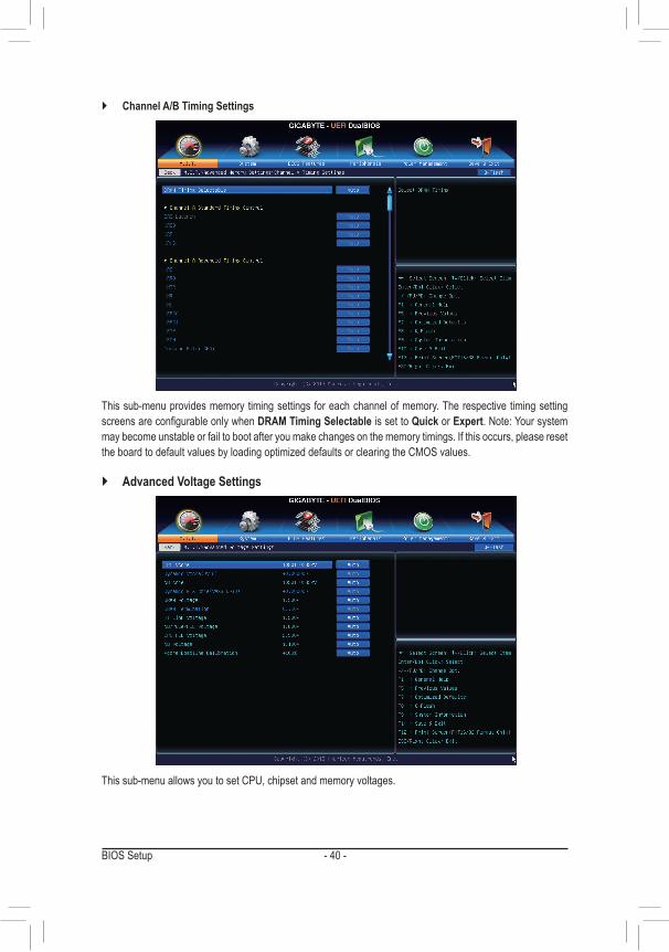
This sub-menu provides memory timing settings for each channel of memory. The respective timing setting screens are configurable only when DRAM Timing Selectable is set to Quick or Expert. Note: Your system may become unstable or fail to boot after you make changes on the memory timings. If this occurs, please reset the board to default values by loading optimized defaults or clearing the CMOS values.
` Channel A/B Timing Settings
` Advanced Voltage Settings
This sub-menu allows you to set CPU, chipset and memory voltages.
BIOS Setup- 41 -
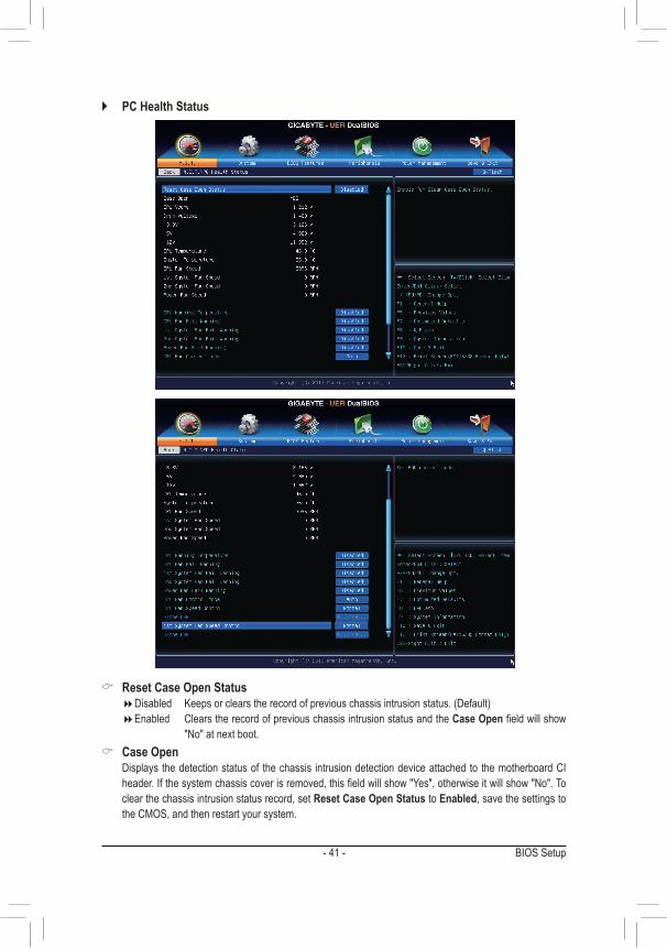
` PC Health Status
& Reset Case Open Status �Disabled Keeps or clears the record of previous chassis intrusion status. (Default) �Enabled Clears the record of previous chassis intrusion status and the Case Open field will show
"No" at next boot. & Case Open
Displays the detection status of the chassis intrusion detection device attached to the motherboard CI header. If the system chassis cover is removed, this field will show "Yes", otherwise it will show "No". To clear the chassis intrusion status record, set Reset Case Open Status to Enabled, save the settings to the CMOS, and then restart your system.
BIOS Setup - 42 -
& CPU Vcore/Dram Voltage/+3.3V/+5V/+12V Displays the current system voltages.
& CPU/System Temperature Displays current CPU/system temperature.
& CPU/System/Power Fan Speed Displays current CPU/system/power fan speed.
& CPU Warning Temperature Sets the warning threshold for CPU temperature. When CPU temperature exceeds the threshold, BIOS
will emit warning sound. Options are: Disabled (default), 60oC/140oF, 70oC/158oF, 80oC/176oF, 90oC/194oF. & CPU/System/Power Fan Fail Warning
Allows the system to emit warning sound if the fan is not connected or fails. Check the fan condition or fan connection when this occurs. (Default: Disabled)
& CPU Fan Control mode �Auto Lets the BIOS automatically detect the type of CPU fan installed and sets the optimal CPU
fan control mode. (Default) �Voltage Sets Voltage mode for a 3-pin CPU fan. �PWM Sets PWM mode for a 4-pin CPU fan.
& CPU Fan Speed Control Allows you to determine whether to enable the fan speed control function and adjust the fan speed.
�Normal Allows the fan to run at different speeds according to the CPU temperature. You can adjust the fan speed with EasyTune based on your system requirements. (Default)
�Silent Allows the fan to run at slow speeds. �Manual Allows you to control the fan speed under the Slope PWM item. �Disabled Allows the fan to run at full speeds.
& Slope PWM Allows you to control the CPU fan speed. This item is configurable only when CPU Fan Speed Control is
set to Manual. Options are: 0.75 PWM value /oC ~ 2.50 PWM value /oC. & 1st System Fan Speed Control (SYS_FAN1 Connector)
Allows you to determine whether to enable the fan speed control function and adjust the fan speed. �Normal Allows the fan to run at different speeds according to the system temperature. You can adjust
the fan speed with EasyTune based on your system requirements. (Default) �Silent Allows the fan to run at slow speeds. �Manual Allows you to control the fan speed under the Slope PWM item. �Disabled Allows the fan to run at full speeds.
& Slope PWM Allows you to control the system fan speed. This item is configurable only when 1st System Fan Speed
Control is set to Manual. Options are: 0.75 PWM value /oC ~ 2.50 PWM value /oC.
BIOS Setup- 43 -
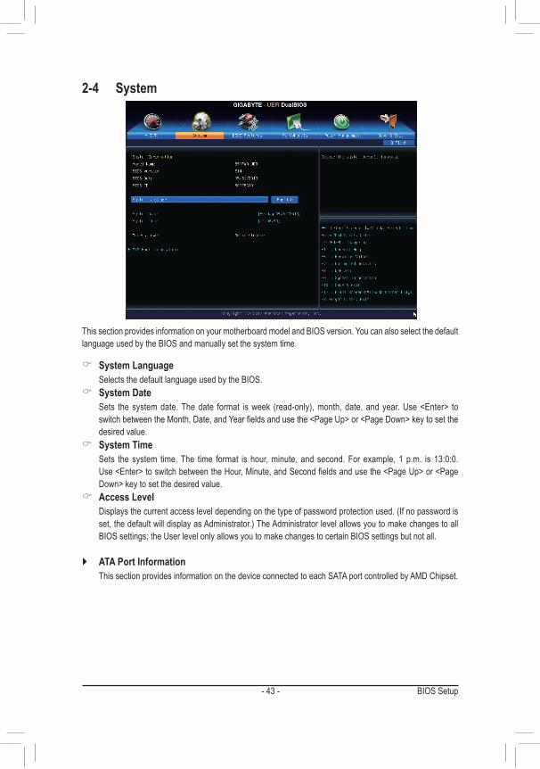
2-4 System
This section provides information on your motherboard model and BIOS version. You can also select the default language used by the BIOS and manually set the system time.
& System Language Selects the default language used by the BIOS.
& System Date Sets the system date. The date format is week (read-only), month, date, and year. Use <Enter> to
switch between the Month, Date, and Year fields and use the <Page Up> or <Page Down> key to set the desired value.
& System Time Sets the system time. The time format is hour, minute, and second. For example, 1 p.m. is 13:0:0.
Use <Enter> to switch between the Hour, Minute, and Second fields and use the <Page Up> or <Page Down> key to set the desired value.
& Access Level Displays the current access level depending on the type of password protection used. (If no password is
set, the default will display as Administrator.) The Administrator level allows you to make changes to all BIOS settings; the User level only allows you to make changes to certain BIOS settings but not all.
` ATA Port Information This section provides information on the device connected to each SATA port controlled by AMD Chipset.
BIOS Setup - 44 -
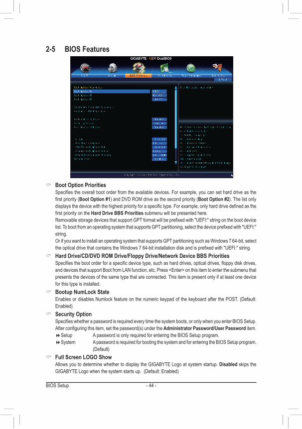
2-5 BIOS Features
& Boot Option Priorities Specifies the overall boot order from the available devices. For example, you can set hard drive as the
first priority (Boot Option #1) and DVD ROM drive as the second priority (Boot Option #2). The list only displays the device with the highest priority for a specific type. For example, only hard drive defined as the first priority on the Hard Drive BBS Priorities submenu will be presented here.
Removable storage devices that support GPT format will be prefixed with "UEFI:" string on the boot device list. To boot from an operating system that supports GPT partitioning, select the device prefixed with "UEFI:" string.
Or if you want to install an operating system that supports GPT partitioning such as Windows 7 64-bit, select the optical drive that contains the Windows 7 64-bit installation disk and is prefixed with "UEFI:" string.
& Hard Drive/CD/DVD ROM Drive/Floppy Drive/Network Device BBS Priorities Specifies the boot order for a specific device type, such as hard drives, optical drives, floppy disk drives,
and devices that support Boot from LAN function, etc. Press <Enter> on this item to enter the submenu that presents the devices of the same type that are connected. This item is present only if at least one device for this type is installed.
& Bootup NumLock State Enables or disables Numlock feature on the numeric keypad of the keyboard after the POST. (Default:
Enabled) & Security Option
Specifies whether a password is required every time the system boots, or only when you enter BIOS Setup. After configuring this item, set the password(s) under the Administrator Password/User Password item.
�Setup A password is only required for entering the BIOS Setup program. �System A password is required for booting the system and for entering the BIOS Setup program.
(Default) & Full Screen LOGO Show
Allows you to determine whether to display the GIGABYTE Logo at system startup. Disabled skips the GIGABYTE Logo when the system starts up. (Default: Enabled)

BIOS Setup- 45 -
& OS Type Allows you to select the operating system to be installed. (Default: Other OS)
& CSM Support Enables or disables UEFI CSM (Compatibility Support Module) to support a legacy PC boot process.
�Always Enables UEFI CSM. (Default) �Never Disables UEFI CSM and supports UEFI BIOS boot process only.
This item is configurable only when OS Type is set to Windows 8. & Boot Mode Selection
Allows you to select which type of operating system to boot. � UEFI and Legacy Allows booting from operating systems that support legacy option ROM or UEFI option
ROM. (Default) �Legacy Only Allows booting from operating systems that only support legacy Option ROM. �UEFI Only Allows booting from operating systems that only support UEFI Option ROM.
This item is configurable only when CSM Support is set to Always. & LAN PXE Boot Option ROM
Allows you to select whether to enable the legacy option ROM for the LAN controller. (Default: Disabled) This item is configurable only when CSM Support is set to Always.
& Storage Boot Option Control Allows you to select whether to enable the UEFI or legacy option ROM for the storage device controller.
�Disabled Disables option ROM. �Legacy Only Enables legacy option ROM only. (Default) �UEFI Only Enables UEFI option ROM only. �Legacy First Enables legacy option ROM first. �UEFI First Enables UEFI option ROM first.
This item is configurable only when CSM Support is set to Always. & Other PCI Device ROM Priority
Allows you to select whether to enable the UEFI or Legacy option ROM for the PCI device controller other than the LAN, storage device, and graphics controllers.
�Legacy OpROM Enables legacy option ROM only. �UEFI OpROM Enables UEFI option ROM only. (Default)
& Network stack Disables or enables booting from the network to install a GPT format OS, such as installing the OS from
the Windows Deployment Services server. (Default: Disable) & Ipv4 PXE Support
Enables or disables IPv4 PXE Support. This item is configurable only when Network stack is enabled. & Ipv6 PXE Support
Enables or disables IPv6 PXE Support. This item is configurable only when Network stack is enabled.
& Administrator Password Allows you to configure an administrator password. Press <Enter> on this item, type the password, and
then press <Enter>. You will be requested to confirm the password. Type the password again and press <Enter>. You must enter the administrator password (or user password) at system startup and when entering BIOS Setup. Differing from the user password, the administrator password allows you to make changes to all BIOS settings.
BIOS Setup - 46 -
& User Password Allows you to configure a user password. Press <Enter> on this item, type the password, and then press
<Enter>. You will be requested to confirm the password. Type the password again and press <Enter>. You must enter the administrator password (or user password) at system startup and when entering BIOS Setup. However, the user password only allows you to make changes to certain BIOS settings but not all.
To cancel the password, press <Enter> on the password item and when requested for the password, enter the correct one first. When prompted for a new password, press <Enter> without entering any password. Press <Enter> again when prompted to confirm.
BIOS Setup- 47 -
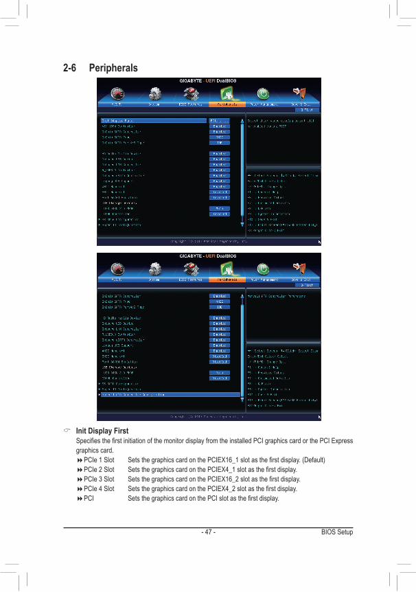
2-6 Peripherals
& Init Display First Specifies the first initiation of the monitor display from the installed PCI graphics card or the PCI Express
graphics card. �PCIe 1 Slot Sets the graphics card on the PCIEX16_1 slot as the first display. (Default) �PCIe 2 Slot Sets the graphics card on the PCIEX4_1 slot as the first display. �PCIe 3 Slot Sets the graphics card on the PCIEX16_2 slot as the first display. �PCIe 4 Slot Sets the graphics card on the PCIEX4_2 slot as the first display. �PCI Sets the graphics card on the PCI slot as the first display.

BIOS Setup - 48 -
& VIA 1394 Controller Enables or disables the onboard IEEE 1394 function. (Default: Enabled)
& OnChip SATA Controller (AMD SB950 SATA Controllers) Enables or disables the integrated SATA controllers. (Default: Enabled)
& OnChip SATA Type (AMD SB950 South Bridge, SATA3 0~3 connectors) Enables or disables RAID for the SATA controllers integrated in the Chipset or configures the SATA controllers
to AHCI mode. �Native IDE Configures the SATA controller to IDE mode. �RAID Enables RAID for the SATA controller. �AHCI Configures the SATA controllers to AHCI mode. Advanced Host Controller Interface
(AHCI) is an interface specification that allows the storage driver to enable advanced Serial ATA features such as Native Command Queuing and hot plug. (Default)
& OnChip SATA Port4/5 Type (AMD SB950 South Bridge, SATA3 4~5 connectors) This option is configurable only when OnChip SATA Type is set to RAID or AHCI. Configures the operating
mode of the integrated SATA3 4~SATA3 5 connectors. �As SATA Type The mode depends on the OnChip SATA Type settings. �IDE Configures the SATA3 4~SATA3 5 connectors to PATA mode. (Default)
& HD Audio Azalia Device Enables or disables the onboard audio function. (Default: Enabled) If you wish to install a 3rd party add-in audio card instead of using the onboard audio, set this item to
Disabled. & Onboard USB Device
Enables or disables the integrated USB controller. (Default: Enabled) & Onboard LAN Controller
Enables or disables the onboard LAN function. (Default: Enabled) If you wish to install a 3rd party add-in network card instead of using the onboard LAN, set this item to
Disabled. & R_USB3.0 Controller (VIA® VL805 USB Controller, USB 3.0/2.0 ports)
Enables or disables the VIA® VL805 USB controller. (Default: Enabled) & Onboard eSATA Controller (Marvell® 88SE9172 Chip, eSATA connectors)
Enables or disables the SATA controller integrated in the Marvell® 88SE9172 chip. (Default: Enabled) & Legacy USB Support
Allows USB keyboard/mouse to be used in MS-DOS. (Default: Enabled) & XHCI Hand-off
Determines whether to enable XHCI Hand-off feature for an operating system without XHCI Hand-off support. (Default: Enabled)
& EHCI Hand-off Determines whether to enable EHCI Hand-off feature for an operating system without EHCI Hand-off
support. (Default: Disabled) & Port 60/64 Emulation
Enables or disables emulation of I/O ports 64h and 60h. This should be enabled for full legacy support for USB keyboards/mice in MS-DOS or in operating system that does not natively support USB devices. (Default: Disabled)

BIOS Setup- 49 -
& USB Storage Devices Displays a list of connected USB mass storage devices. This item appears only when a USB storage device
is installed. & IOMMU Controller
Enables or disables AMD IOMMU support. (Default: Disabled) ` Trusted Computing & TPM SUPPORT
Enables or disables Trusted Platform Module (TPM). Set this item to Enable when a TPM device is installed. (Default: Disable)
` SB SATA Configuration
& SATA Hot Plug on PORT0~SATA Hot Plug on PORT5 Enables or disable the hot plug capability for each SATA port. (Default: Disabled)
& SATA Power on PORT0~SATA Power on PORT5 Enables or disables each SATA port. (Default: Enabled)

BIOS Setup - 50 -
` Marvell ATA Controller Configuration
& GSATA Controller (Marvell® 88SE9172 Chip, eSATA connectors) Enables or disables RAID for the SATA controller integrated in the Marvell® 88SE9172 chip or configures
the SATA controller to AHCI mode. �IDE Mode Disables RAID for the SATA controller and configures the SATA controller to IDE mode. �AHCI Mode Configures the SATA controller to AHCI mode. Advanced Host Controller Interface
(AHCI) is an interface specification that allows the storage driver to enable advanced Serial ATA features such as Native Command Queuing and hot plug. (Default)
�RAID Mode Enables RAID for the SATA controller.
BIOS Setup- 51 -
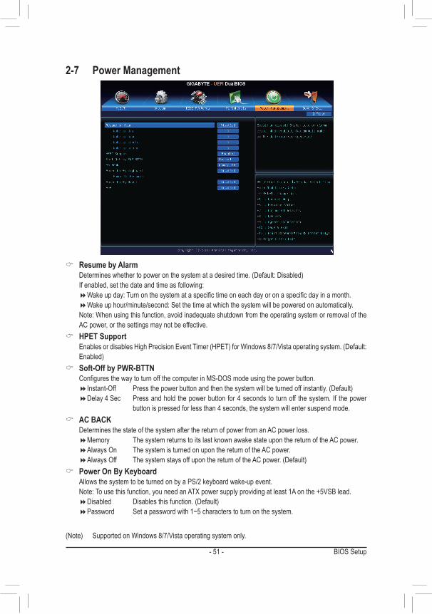
& Resume by Alarm Determines whether to power on the system at a desired time. (Default: Disabled) If enabled, set the date and time as following:
�Wake up day: Turn on the system at a specific time on each day or on a specific day in a month. �Wake up hour/minute/second: Set the time at which the system will be powered on automatically.
Note: When using this function, avoid inadequate shutdown from the operating system or removal of the AC power, or the settings may not be effective.
& HPET Support Enables or disables High Precision Event Timer (HPET) for Windows 8/7/Vista operating system. (Default:
Enabled) & Soft-Off by PWR-BTTN
Configures the way to turn off the computer in MS-DOS mode using the power button. �Instant-Off Press the power button and then the system will be turned off instantly. (Default) �Delay 4 Sec Press and hold the power button for 4 seconds to turn off the system. If the power
button is pressed for less than 4 seconds, the system will enter suspend mode. & AC BACK
Determines the state of the system after the return of power from an AC power loss. �Memory The system returns to its last known awake state upon the return of the AC power. �Always On The system is turned on upon the return of the AC power. �Always Off The system stays off upon the return of the AC power. (Default)
& Power On By Keyboard Allows the system to be turned on by a PS/2 keyboard wake-up event. Note: To use this function, you need an ATX power supply providing at least 1A on the +5VSB lead.
�Disabled Disables this function. (Default) �Password Set a password with 1~5 characters to turn on the system.
2-7 Power Management
(Note) Supported on Windows 8/7/Vista operating system only.

BIOS Setup - 52 -
�Keyboard 98 Press POWER button on the Windows 98 keyboard to turn on the system. �Any key Press any key to turn on the system.
& Power On Password Set the password when Power On By Keyboard is set to Password. Press <Enter> on this item and set a password with up to 5 characters and then press <Enter> to accept.
To turn on the system, enter the password and press <Enter>. Note: To cancel the password, press <Enter> on this item. When prompted for the password, press <Enter>
again without entering the password to clear the password settings. & Power On By Mouse
Allows the system to be turned on by a PS/2 mouse wake-up event. Note: To use this function, you need an ATX power supply providing at least 1A on the +5VSB lead.
�Disabled Disables this function. (Default) �Move Move the mouse to turn on the system. �Double Click Double click on left button on the mouse to turn on the system.
& ErP Determines whether to let the system consume least power in S5 (shutdown) state. (Default: Disabled) Note: When this item is set to Enabled, the following functions will become unavailable: PME event wake
up, power on by mouse, power on by keyboard, and wake on LAN.
BIOS Setup- 53 -
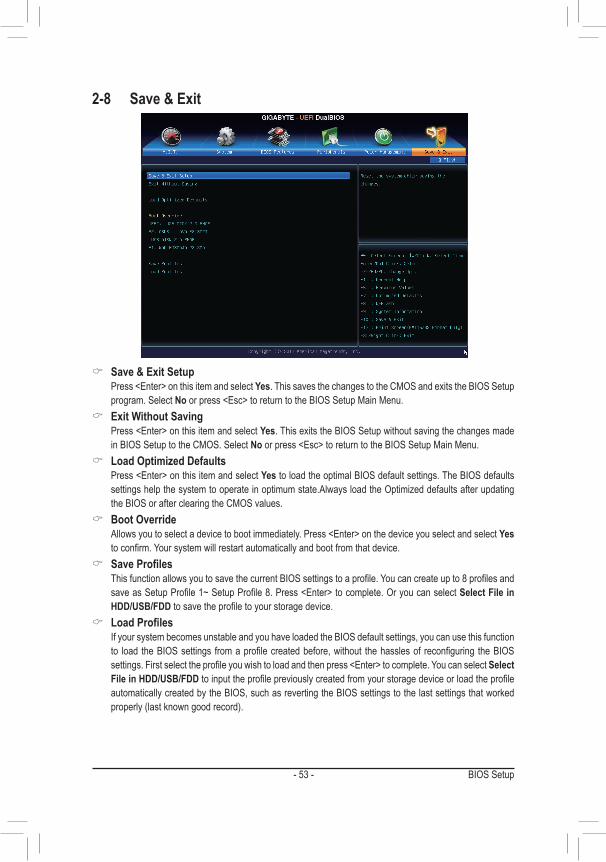
2-8 Save & Exit
& Save & Exit Setup Press <Enter> on this item and select Yes. This saves the changes to the CMOS and exits the BIOS Setup
program. Select No or press <Esc> to return to the BIOS Setup Main Menu. & Exit Without Saving
Press <Enter> on this item and select Yes. This exits the BIOS Setup without saving the changes made in BIOS Setup to the CMOS. Select No or press <Esc> to return to the BIOS Setup Main Menu.
& Load Optimized Defaults Press <Enter> on this item and select Yes to load the optimal BIOS default settings. The BIOS defaults
settings help the system to operate in optimum state.Always load the Optimized defaults after updating the BIOS or after clearing the CMOS values.
& Boot Override Allows you to select a device to boot immediately. Press <Enter> on the device you select and select Yes
to confirm. Your system will restart automatically and boot from that device. & Save Profiles
This function allows you to save the current BIOS settings to a profile. You can create up to 8 profiles and save as Setup Profile 1~ Setup Profile 8. Press <Enter> to complete. Or you can select Select File in HDD/USB/FDD to save the profile to your storage device.
& Load Profiles If your system becomes unstable and you have loaded the BIOS default settings, you can use this function
to load the BIOS settings from a profile created before, without the hassles of reconfiguring the BIOS settings. First select the profile you wish to load and then press <Enter> to complete. You can select Select File in HDD/USB/FDD to input the profile previously created from your storage device or load the profile automatically created by the BIOS, such as reverting the BIOS settings to the last settings that worked properly (last known good record).

BIOS Setup - 54 -

- 55 - Configuring SATA Hard Drive(s)
Chapter 3 Configuring SATA Hard Drive(s)
(Note 1) Skip this step if you do not want to create RAID array on the SATA controller.(Note 2) Required when the SATA controller is set to AHCI or RAID mode.
RAID 0 RAID 1 RAID 5 RAID 10Minimum Number of Hard Drives
≥2 2 ≥3 ≥4
Array Capacity Number of hard drives * Size of the smallest drive
Size of the smallest drive
(Number of hard drives -1) * Size of the smallest drive
(Number of hard drives/2) * Size of the smallest drive
Fault Tolerance No Yes Yes Yes
RAID Levels
To configure SATA hard drive(s), follow the steps below:A. Install SATA hard drive(s) in your computer.B. Configure SATA controller mode in BIOS Setup.C. Configure a RAID array in RAID BIOS (Note 1)
D. Install the SATA RAID/AHCI driver and operating system (Note 2)
Before you begin • At least two SATA hard drives (to ensure optimal performance, it is recommended that you use two hard drives with identical model and capacity). If you do not want to create RAID, you may prepare only one hard drive.
• Windows 8/7/XP setup disk. • Motherboard driver disk. • A USB flash drive. • A USB floppy disk drive (needed during Windows XP installation). • An empty formatted floppy disk (needed during Windows XP installation).
3-1 Configuring AMD SB950 SATA Controllers
A. Installing SATA hard drive(s) in your computerAttach one end of the SATA signal cable to the rear of the SATA hard drive and the other end to available SATA port on the motherboard. If there is more than one SATA controller on your motherboard, refer to "Chapter 1," "Hardware Installation," to identify the SATA controller for the SATA port. (For example, on this motherboard, the SATA3 0~SATA3 5 ports are supported by the AMD SB950 South Bridge.) Then connect the power connector from your power supply to the hard drive.Then connect the power connector from your power supply to the hard drive

Configuring SATA Hard Drive(s) - 56 -
The BIOS Setup menus described in this section may differ from the exact settings for your motherboard. The actual BIOS Setup menu options you will see shall depend on the motherboard you have and the BIOS version.
B. Configuring SATA controller mode in BIOS SetupMake sure to configure the SATA controller mode correctly in system BIOS Setup. Step 1:Turn on your computer and press <Delete> to enter BIOS Setup during the POST (Power-On Self-Test). Ensure OnChip SATA Channel is enabled under Peripherals. To enable RAID for the SATA3 0/1/2/3 connectors, set OnChip SATA Type to RAID. To enable RAID for the SATA3 4/SATA3 5 connectors, set OnChip SATA Type to RAID and set OnChip SATA Port4/5 Type to As SATA Type.
Figure 1
Step 2:If you want to configure UEFI RAID, follow the steps in "C-1." To enter the legacy RAID ROM, save the settings and exit BIOS Setup. Refer to "C-2" for more information.

- 57 - Configuring SATA Hard Drive(s)
C-1. UEFI RAID ConfigurationThis mode supports Windows 8 64-bit installation only.Step 1:In BIOS Setup, go to BIOS Features and set OS Type to Windows 8 and CSM Support to Never. (Figure 2) Save the changes and exit BIOS Setup.
Step 2:Restart your computer and press <F12> to enter the boot device configuration menu. Use the up or down arrow key to select UEFI: Built-in EFI Shell. Press <Enter> to access the screen as shown in Figure 3. Follow the steps below and enter the commands to access the RAID setup utility.1. Enter drvcfg at Shell and press <Enter>: Shell> drvcfg2. When Drv [XX] Ctrl [XX] Lang [eng] appears, enter the following commands at Shell again: Shell> drvcfg -s XX XX (XXs are the values shown in the brackets after Drv and Ctrl above, which may vary by hard drives.)Then press <Enter> to enter the RAID setup utility.
Figure 2
Figure 3
EFI Shell version 2.31 [4.653]Current running mode 1.1.2Device mapping table fs0 : Removable HardDisk Alias hd12d0b blk0 PciRoot (0x0)/Pci (0x10, 0x0)/USB (0x3, 0x0)/HD (1.MBR,0x016777a6, 0x3f, 0x1e1fc0) fs1 : Removable CDRom Alias cd14c0b blk1 PciRoot (0x0)/Pci (0x11, 0x0)/Scsi (0x2, 0x0)/CDROM (0x1,0x6e, 0X1A0263) ......
Press ESC in 1 seconds to skip startup.nsh, any other key to continue. Shell> drvcfgConfigurable Components Drv [59] Ctrl [CF] Lang [eng]
Shell> drvcfg -s 59 cf
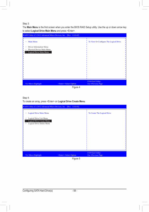
Configuring SATA Hard Drive(s) - 58 -
Step 3:The Main Menu is the first screen when you enter the BIOS RAID Setup utility. Use the up or down arrow key to select Logical Drive Main Menu and press <Enter>.
Figure 4
Figure 5
RAID Utility (C) 2012 Advanced Micro Devices, Inc. [Rev. 1.0.0.45]
F10=Exit Utility hi=Move Highlight <Enter>=Select Option Esc=Previous Page
+ Main Menu
+ Driver Information Menu+ Physical Device Main Menu+ Logical Drive Main Menu
To View Or Configure The Logical Drive
Step 4:To create an array, press <Enter> on Logical Drive Create Menu.
RAID Utility (C) 2012 Advanced Micro Devices, Inc. [Rev. 1.0.0.45]
F10=Exit Utility hi=Move Highlight <Enter>=Select Option Esc=Previous Page
+ Logical Drive Main Menu
+ Logical Drive List Menu+ Logical Drive Create Menu+ Logical Drive Delete Menu
To Create The Logical Drive

- 59 - Configuring SATA Hard Drive(s)
Step 5:Usable hard drives are listed on the Logical Drive Create Menu. Use the up or down arrow key to select the hard drive to be included in the array and press the <Space> key. The selected hard drives will be marked with [X]. Then move to Basic Setting and press <Enter>.
Step 6:Use the up or down arrow key to move to and configure each required item in sequence.After completing, press <Enter> on Start To Create (Figure 7). When the message "Are You Sure To Create Logical Drive?" appears, press <Enter> to begin creating the RAID array or <Esc> to cancel.
When completed, a message which says "Successful To Create Logical Drive" will appear. Press <Enter> to complete. Press <F10> to exit the RAID setup utility.
Figure 6
Figure 7
RAID Utility (C) 2012 Advanced Micro Devices, Inc. [Rev. 1.0.0.45]
F10=Exit Utility hi=Move Highlight <Space>=Toggle Checkbox Esc=Previous Page
+ Logical Drive Create Menu
+ Usable Physical Drive List- Hitachi HDT721032SLA360 | 500.10 GB [X]- Hitachi HDT721032SLA360 | 500.10 GB [X]
+ Basic Setting
Usable Physical Disk On(Port : 4, TargetId : 1)
RAID Utility (C) 2012 Advanced Micro Devices, Inc. [Rev. 1.0.0.45]
F10=Exit Utility hi=Move Highlight <Enter>=Select Option Esc=Previous Page
+ Logical Drive Create Menu
- Raid Mode : <RAID 0>- Stripe Block (KB) : <64>- Setcor Size (Bytes) : <512>- Initialization : <Fast>- Gigabyte Boundary : <Enable>- Read Policy : <Read Ahead>- Write Policy : <Write Back>- Ld Name : GBT
+ Ld Size Setting- Ld Max Size : 1000.21 GB- Ld Size (GB) : [0]
+ Start To Create
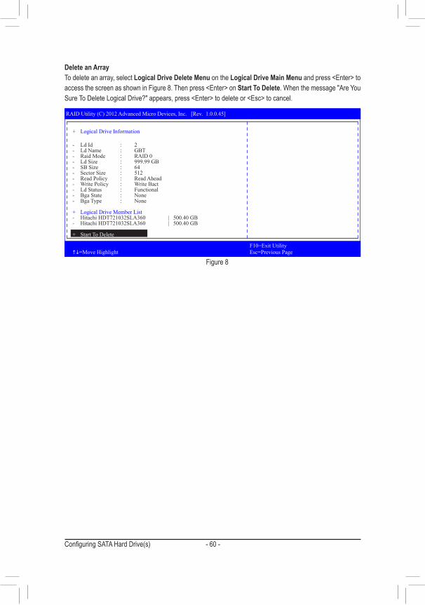
Configuring SATA Hard Drive(s) - 60 -
Figure 8
Delete an ArrayTo delete an array, select Logical Drive Delete Menu on the Logical Drive Main Menu and press <Enter> to access the screen as shown in Figure 8. Then press <Enter> on Start To Delete. When the message "Are You Sure To Delete Logical Drive?" appears, press <Enter> to delete or <Esc> to cancel.
RAID Utility (C) 2012 Advanced Micro Devices, Inc. [Rev. 1.0.0.45]
F10=Exit Utility hi=Move Highlight Esc=Previous Page
+ Logical Drive Information
- Ld Id : 2- Ld Name : GBT- Raid Mode : RAID 0- Ld Size : 999.99 GB- SB Size : 64- Sector Size : 512- Read Policy : Read Ahead- Write Policy : Write Bact- Ld Status : Functional- Bga State : None- Bga Type : None
+ Logical Drive Member List- Hitachi HDT721032SLA360 | 500.40 GB- Hitachi HDT721032SLA360 | 500.40 GB
+ Start To Delete

- 61 - Configuring SATA Hard Drive(s)
C-2. Configuring Legacy RAID ROMEnter the RAID BIOS setup utility to configure a RAID array. Skip this step if you do not want to create RAID array on the SATA controller.
Step 1:After the POST memory test begins and before the operating system boot begins, look for a message which says "Press <Ctrl-F> to enter RAID Option ROM Utility" (Figure 2). Press <Ctrl> + <F> to enter the RAID BIOS setup utility.
Figure 2
Step 2:Main MenuThis is the first option screen when you enter the BIOS RAID Setup utility. (Figure 3)To view the disk drives assigned to arrays, press <1> to enter the View Drive Assignments window.To create an array, press <2> to enter the LD View/LD Define Menu window.To delete an array, press <3> to enter the Delete LD Menu window.To view controller settings, press <4> to enter the Controller Configuration window.
Figure 3
RAID Option ROM Version 3.3.1540.17(c) 2011 Advanced Micro Devices, Inc. All rights reserved.
No Array is defined..
Press <Ctrl-F> to enter RAID Option ROM Utility...
View Drive Assignments........................... [ 1 ]
LD View/ LD Define Menu...................... [ 2 ]
Delete LD Menu....................................... [ 3 ]
Controller Configuration............................ [ 4 ]
Option ROM Utility (c) 2011 Advanced Micro Devices, Inc.
Press 1..4 to Select Option [ESC] Exit
[ Keys Available ]
[ Main Menu ]

Configuring SATA Hard Drive(s) - 62 -
In the LD Define Menu, use the up or down arrow key to move to an item for further configuration (Figure 5).
Figure 4
Figure 5
Create a RAID ArrayTo create a new array, press <2> to enter the LD View Menu window (Figure 4). To create an array, press <Ctrl+C> to access the LD Define Menu.
Option ROM Utility (c) 2011 Advanced Micro Devices, Inc.
[ LD View Menu ]
< There is no any LD >
[h] Up [i] Down [PaUp/PaDn] Switch Page [Ctrl+C] Define LD [Enter] View LD [Ctrl+V] View Single Disk [ESC] Exit
[ Keys Available ]
[ Keys Available ]
Option ROM Utility (c) 2011 Advanced Micro Devices, Inc.
[ LD Define Menu ]
[h] Up [i] Down [PaUp/PaDn] Switch Page [Space] Change Option [Ctrl+Y] Save [ESC] Exit
[ Keys Available ]
[ Drives Assignments ]
Port:ID Drive Model Capabilities Capacity (GB) Assignment 01:00 WDC WD800JD-22LSA0 SATA 3G 79.89 N 02:00 WDC WD800JD-22LSA0 SATA 3G 80.02 N
LD No LD Name RAID Mode Drv LD 1 Logical Drive 1 RAID 0 0
Stripe Block 64 KB Initialization FastGigabyte Boundary ON Read Policy Read Ahead Write Policy WriteBack

- 63 - Configuring SATA Hard Drive(s)
In the following procedure, we'll create RAID 0 as an example.Steps:1. Under the RAID Mode section, press the <SPACE> key to select RAID 0.2. Set the Stripe Block size. 64 KB is the default.3. Under the Drives Assignments section, press the up or down arrow key to highlight a drive.4. Press the <SPACE> key or <Y> to change the Assignment option to Y. This action adds the drive to the
disk array. The Drv section will show the number of disks assigned. 5. Press <Ctrl>+<Y> keys to save the information. The message in Figure 6 will appear. Press <Ctrl>+<Y> to
input the array name. If you do not input the array name, the default array name will be used.
Figure 7
Figure 8
7. Press <Ctrl>+<Y> to set the capacity of the RAID array or press other keys to set the array to its maximum capacity.
8. After the creation is complete, the screen will return to LD View Menu where you will see the newly-created array.
9. Press <Esc> to return to Main Menu and press <Esc> again if you want to exit the RAID BIOS utility.
Fast Initialization Option has been selectedIt will erase the MBR data of the disk.<Press Ctrl-Y Key if you are sure to erase it><Press any other key to ignore this option>
Press Ctrl-Y to Modify Array Capacity or press any other key to use maximum capacity...
Figure 6
Please press Ctrl-Y key to input the LD Nameor press any key to exit.If you do not input any LD name, the defaultLD name will be used.
6. When the next message appears, press <Ctrl>+<Y> to clear the MBR or press other keys to ignore this option. Then, the message in Figure 8 will appear.

Configuring SATA Hard Drive(s) - 64 -
Delete an ArrayThe Delete Array menu option allows for deletion of disk array assignments.
1. To delete an array, press <3> in the Main Menu to enter the Delete LD Menu. Then highlight the array you wish to delete and press the <Delete> key or the <Alt>+<D> keys.
2. The View LD Definition Menu will appear (as shown in Figure 10) showing which drives are assigned to this array. Press <Ctrl>+<Y> if you are sure to delete the array or other keys to abort.
3. When the array is deleted, the screen will return to Delete LD Menu. Press <Esc>to return to Main Menu.
Figure 10
Deleting an existing disk array could result in loss of data. Record all array information including the array type, the disk members, and stripe block size in case you wish to undo a deletion.
View Drive AssignmentsThe View Drive Assignments option in the Main Menu displays whether the attached hard drives are assigned to a disk array or are unassigned. Under the Assignment column, drives are labeled with their assigned disk array or shown as Free if unassigned.
Figure 9
Option ROM Utility (c) 2011 Advanced Micro Devices, Inc.
[ Keys Available ]
[ View Drives Assignments ]
[h] Up [i] Down [PaUp/PaDn] Switch Page [Ctrl+H] Secure Erase [ESC] Exit
Port:ID Drive Model Capabilities Capacity (GB) Assignment 01:00 WDC WD800JD-22LSA0 SATA 3G 79.89 [S.M.A.R.T.] Health Extent 1 79.82 LD 1-1 02:00 WDC WD800JD-22LSA0 SATA 3G 80.2 [S.M.A.R.T.] Health Extent 1 80.02 LD 1-2
[ Keys Available ]
Option ROM Utility (c) 2011 Advanced Micro Devices, Inc.
[ View LD Definition Menu ]
[ Keys Available ]
[ Drives Assignments ]
Port:ID Drive Model Capabilities Capacity (GB) 01:00 WDC WD800JD-22LSA0 SATA 3G 79.89 02:00 WDC WD800JD-22LSA0 SATA 3G 80.02
Press Ctrl-Y to delete the data in the disk!or press any other key to abort...
LD No LD Name RAID Mode Drv Capacity(GB)
LD 1 GBT RAID 0 2 80
Stripe Block 64 KB Sector Size 512 BRead Policy Read Ahead Write Policy WriteBack
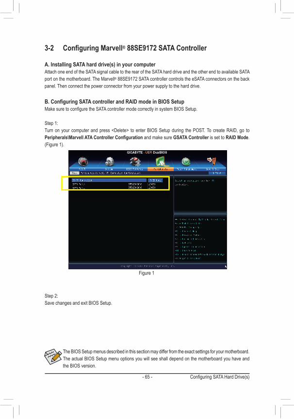
- 65 - Configuring SATA Hard Drive(s)
3-2 Configuring Marvell® 88SE9172 SATA Controller
A. Installing SATA hard drive(s) in your computerAttach one end of the SATA signal cable to the rear of the SATA hard drive and the other end to available SATA port on the motherboard. The Marvell® 88SE9172 SATA controller controls the eSATA connectors on the back panel. Then connect the power connector from your power supply to the hard drive.
B. Configuring SATA controller and RAID mode in BIOS SetupMake sure to configure the SATA controller mode correctly in system BIOS Setup.
Step 1: Turn on your computer and press <Delete> to enter BIOS Setup during the POST. To create RAID, go to Peripherals\Marvell ATA Controller Configuration and make sure GSATA Controller is set to RAID Mode. (Figure 1).
Figure 1
The BIOS Setup menus described in this section may differ from the exact settings for your motherboard. The actual BIOS Setup menu options you will see shall depend on the motherboard you have and the BIOS version.
Step 2:Save changes and exit BIOS Setup.

Configuring SATA Hard Drive(s) - 66 -
Figure 2
C. Configuring a RAID array in RAID BIOSEnter the RAID BIOS setup utility to configure a RAID array. Skip this step and proceed to the installation of Windows operating system for a non-RAID configuration. After the POST memory test begins and before the operating system boot begins, look for a message which says "Press <Ctrl>+<M> to enter BIOS Setup or <Space> to continue" (Figure 2). Press <Ctrl> + <M> to enter the RAID setup utility.
On the main screen of the RAID setup utility (Figure 3), use the left or right arrow key to move through tabs.
Figure 3
Marvell 88SE91xx Adapter - BIOS Version 1.0.1.0027PCIe x1 5.0GbpsMode: RAID[Virtual Disks] No Virtual Disk![Physical Disks]Adapter 0Port Disk Name Size Max SpeedS0 SATA: WDC WD800JD-22LSA0 76.3GB SATA 3Gb/sS1 SATA: WDC WD800JD-22LSA0 76.3GB SATA 3Gb/s
Press <Ctrl>+<M> to enter BIOS Setup or <Space> to continue_
ENTER/SPACE: Select, ESC: Back/Exit
Adapter 0
[ Adapter ][ Selection ] [ Devices ] [ RAID ]
Vendor ID Device ID: 1B4B:91A2BIOS Version: 1.0.0.0027PCI Slot: 00IRQ Number: 0BRaid Mode: RAID0 RAID1
Marvell BIOS Setup (c) 2009 Marvell Technology Group Ltd.
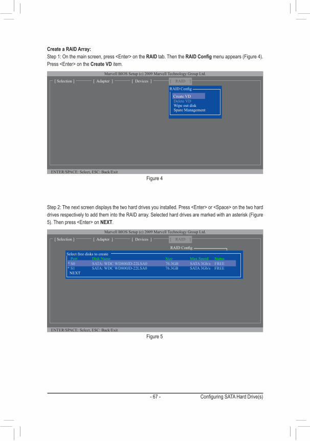
- 67 - Configuring SATA Hard Drive(s)
Figure 4
Create a RAID Array:Step 1: On the main screen, press <Enter> on the RAID tab. Then the RAID Config menu appears (Figure 4). Press <Enter> on the Create VD item.
Figure 5
Step 2: The next screen displays the two hard drives you installed. Press <Enter> or <Space> on the two hard drives respectively to add them into the RAID array. Selected hard drives are marked with an asterisk (Figure 5). Then press <Enter> on NEXT.
ENTER/SPACE: Select, ESC: Back/Exit
Marvell BIOS Setup (c) 2009 Marvell Technology Group Ltd.
[ Adapter ][ Selection ] [ Devices ] [ RAID ]
Delete VD Wipe out disk Spare Management
RAID Config
Create VD
ENTER/SPACE: Select, ESC: Back/Exit
Marvell BIOS Setup (c) 2009 Marvell Technology Group Ltd.
[ Adapter ][ Selection ] [ Devices ] [ RAID ]
RAID Config
Port Disk Name Size Max Speed Status * S1 SATA: WDC WD800JD-22LSA0 76.3GB SATA 3Gb/s FREE NEXT
Select free disks to create
* S0 SATA: WDC WD800JD-22LSA0 76.3GB SATA 3Gb/s FREE

Configuring SATA Hard Drive(s) - 68 -
Figure 6
Step 3: On the Create VD menu (Figure 6), use the up or down arrow key to move the selection bar to select an item and press <Enter> to display options. Set the required items in sequence and press the down arrow key to proceed to the next item. Sequence:1. RAID Level: Select a RAID level. Options include RAID 0 (Stripe) and RAID 1 (Mirror). 2. Stripe Size: Select the stripe block size. Options include 32 KB, 64 KB, and 128 KB. 3. Quick Init: Select whether to quickly erase old data on the hard drives when creating the array. 4. Cache Mode: Select write-back or write-through cache. 5. VD Name: Enter an array name with 1~10 letters (letters cannot be special characters).
Figure 7
6. NEXT: After completing the settings above, move to NEXT and press <Enter> to begin creating the array. When prompted to confirm, press <Y> to confirm or <N> to cancel (Figure 7).
ENTER/SPACE: Select, ESC: Back/Exit
Marvell BIOS Setup (c) 2009 Marvell Technology Group Ltd.
[ Adapter ][ Selection ] [ Devices ] [ RAID ]
RAID Config
Port Disk Name Size Max Speed Status * S0 SATA: WDC WD800JD-22LSA0 76.3GB SATA 3Gb/s FREE * S1 SATA: WDC WD800JD-22LSA0 76.3GB SATA 3Gb/s FREE
Select free disks to create
RAID Level : Max Size (MB): 152478Stripe Size : 64KBQuick Init : NoCache Mode : WriteBackVD Name : Disks ID : 0 1NEXT
Create VDRAID0
Marvell BIOS Setup (c) 2009 Marvell Technology Group Ltd.
[ Adapter ][ Selection ] [ Devices ] [ RAID ]
Create the VD?[Y]
RAID Config
Port Disk Name Size Max Speed Status * S0 SATA: WDC WD800JD-22LSA0 76.3GB SATA 3Gb/s FREE * S1 SATA: WDC WD800JD-22LSA0 76.3GB SATA 3Gb/s FREE NEXT
Select free disks to create
RAID Level : RAID0 Max Size (MB): 152478Stripe Size : 64KBQuick Init : NoCache Mode : WriteBackVD Name : GBTDisk ID : 01
Create VD
NEXT

- 69 - Configuring SATA Hard Drive(s)
To exit the RAID BIOS utility, press <Esc> on the main screen and press <Y> to confirm.Now, you can proceed to install the operating system.
When completed, the RAID tab will display the new array (Figure 8).
Figure 8
Delete the RAID Array:To deleted the existing array, press <Enter> on the RAID tab and select Delete VD. When the Delete VD menu appears, press <Enter> on the array to select it and then press <Enter> on NEXT. When prompted, press <Y> to confirm (Figure 9). When the message "Do you want to delete the VD's MBR?" appears, press <Y> to clear the MBR or press other keys to ignore.
Figure 9
Use the Marvell® Storage Utility in the Operating System: With the Marvell® Storage utility, you can set up an array or view the current array status in the operating system. To install the utility, insert the motherboard driver disk, then go to Application Software\Install Application Software and select Marvell Storage Utility to install. Note: After the installation, you must login the utility with the same account name and password that you use to login the operating system. If you did not set the account password before, click Login to enter the Marvell Storage Utility directly. Please note that if you set the hard drive(s) to IDE or AHCI mode, it is normal that you will not see the hard drive(s) in the Marvell Storage Utility.
ENTER/SPACE: Select, ESC: Back/Exit
Marvell BIOS Setup (c) 2009 Marvell Technology Group Ltd.
[Virtual Disks]ID Name Size Level Status Stripe CacheMode0 GBT 152.4GB RAID0 ONLINE 64KB WriteBack[Physical Disks]Port Disk Name Size Max Speed StatusS0 SATA: WDC WD800JD-22LSA0 76.3GB SATA 3Gb/s ASSIGNEDS1 SATA: WDC WD800JD-22LSA0 76.3GB SATA 3Gb/s ASSIGNED
[ Adapter ][ Selection ] [ Devices ] [ RAID ]
Marvell BIOS Setup (c) 2009 Marvell Technology Group Ltd.
Delete the VD?[Y]
RAID Config
ID Name Size Level Status Stripe CacheMode* 0 GBT 152.4GB RAID0 ONLINE 64KB WriteBack
NEXT
Delete VD
[ Adapter ][ Selection ] [ Devices ] [ RAID ]

Configuring SATA Hard Drive(s) - 70 -
3-3 Installing the SATA RAID/AHCI Driver and Operating SystemWith the correct BIOS settings, you are ready to install the operating system.
A. Installing Windows 8/7(The following instructions use Windows 8 as the example operating system.)For the AMD SB950:Step 1:You need to install the SATA RAID/AHCI driver during the OS installation. Use an alternative system to copy the SATA RAID/AHCI driver from the motherboard driver disk to a USB flash drive. Copy the Hw8 folder under BootDrv in the driver disk.
Step 2:Boot from the Windows 8 setup disk and perform standard OS installation steps. When the screen requesting you to load the driver appears, select Browse.
Step 3:Then browse to the USB flash drive and select the location of the driver. The locations of the drivers are as follows:RAID driver for Windows 8 32-bit: Hw8\RAID\x86 RAID driver for Windows 8 64-bit: Hw8\RAID\x64 AHCI driver for Windows 8 32-bit: Hw8\AHCI\W8 AHCI driver for Windows 8 64-bit: Hw8\AHCI\W864A For Windows 7, browse to the Hw7 folder.
Step 4:When a screen as shown in Figure 1 appears, select AMD AHCI Compatible RAID Controller and click Next to load the driver and continue the OS installation.
Figure 1

- 71 - Configuring SATA Hard Drive(s)
For the Marvell® 88SE9172:Step 1: Copy the Marvell folder under BootDrv in the driver disk to your USB flash drive.
Step 2: Boot from the Windows 8/7 setup disk and perform standard OS installation steps. When the screen requesting you to load the driver appears, select Browse.
Step 3: Insert the USB flash drive and then browse to the location of the driver. The locations of the drivers are as follows:RAID driver for Windows 32-bit: \BootDrv\Marvell\RAID\Floppy32RAID driver for Windows 64-bit: \BootDrv\Marvell\RAID\Floppy64AHCI driver for Windows 32-bit: \BootDrv\Marvell\AHCI\Floppy32AHCI driver for Windows 64-bit: \BootDrv\Marvell\AHCI\Floppy64
Step 4: When a screen as shown in Figure 2 appears, select Marvell 91xx SATA 6G RAID Controller and click Next to load the driver and continue the OS installation.
Figure 2
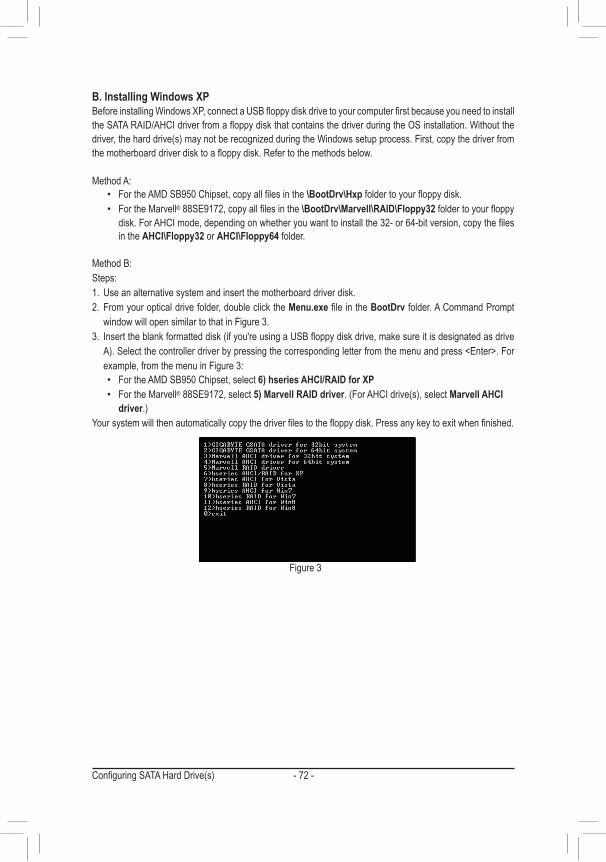
Configuring SATA Hard Drive(s) - 72 -
Figure 3
B. Installing Windows XPBefore installing Windows XP, connect a USB floppy disk drive to your computer first because you need to install the SATA RAID/AHCI driver from a floppy disk that contains the driver during the OS installation. Without the driver, the hard drive(s) may not be recognized during the Windows setup process. First, copy the driver from the motherboard driver disk to a floppy disk. Refer to the methods below.
Method A: • For the AMD SB950 Chipset, copy all files in the \BootDrv\Hxp folder to your floppy disk. • For the Marvell® 88SE9172, copy all files in the \BootDrv\Marvell\RAID\Floppy32 folder to your floppy
disk. For AHCI mode, depending on whether you want to install the 32- or 64-bit version, copy the files in the AHCI\Floppy32 or AHCI\Floppy64 folder.
Method B:Steps: 1. Use an alternative system and insert the motherboard driver disk.2. From your optical drive folder, double click the Menu.exe file in the BootDrv folder. A Command Prompt
window will open similar to that in Figure 3.3. Insert the blank formatted disk (if you're using a USB floppy disk drive, make sure it is designated as drive
A). Select the controller driver by pressing the corresponding letter from the menu and press <Enter>. For example, from the menu in Figure 3:
• For the AMD SB950 Chipset, select 6) hseries AHCI/RAID for XP • For the Marvell® 88SE9172, select 5) Marvell RAID driver. (For AHCI drive(s), select Marvell AHCI
driver.)Your system will then automatically copy the driver files to the floppy disk. Press any key to exit when finished.

- 73 - Configuring SATA Hard Drive(s)
Figure 4
Refer to the following for installing the driver during the Windows setup process.Step 1:Restart your system to boot from the Windows XP setup disk and press <F6> as soon as you see the message "Press F6 if you need to install a 3rd party SCSI or RAID driver." A screen will then appear asking you to specify an additional SCSI adapter. Press <S>.
For the AMD SB950:Step 2:Insert the floppy disk containing the SATA RAID/AHCI driver and press <Enter>. Then a controller menu similar to that in Figure 4 will appear. Select AMD AHCI Compatible RAID Controller-x86 platform and press <Enter>.
Windows Setup
You have chosen to configure a SCSI Adapter for use with Windows, using a device support disk provided by an adapter manufacturer.
Select the SCSI Adapter you want from the following list, or press ESC to return to the previous screen.
ENTER=Select F3=Exit
AMD AHCI Compatible RAID Controller-x86 platformAMD AHCI Compatible RAID Controller-x64 platform

Configuring SATA Hard Drive(s) - 74 -
Step 3:On the next screen, press <Enter> to continue the driver installation. After the driver installation, you can proceed with the Windows XP installation.
For the Marvell® 88SE9172:Insert the floppy disk containing the SATA RAID/AHCI driver and press <Enter>. Both of the Marvell shared library and Marvell 91xx SATA Controller need to be installed. Below we assume that you are installing the 32-bit version. First select Marvell shared library (install first) and press <Enter>. On the next screen, press <S> to return to the screen in Figure 5. Then select Marvell 91xx SATA Controller 32bit Driver and press <Enter>. When both of the two drivers appear on the confirmation screen, press <Enter> to continue the driver installation.
Figure 5
Windows Setup
You have chosen to configure a SCSI Adapter for use with Windows, using a device support disk provided by an adapter manufacturer.
Select the SCSI Adapter you want from the following list, or press ESC to return to the previous screen.
ENTER=Select F3=Exit
Marvell shared library (install first)Marvell 91xx SATA Controller 32bit Driver
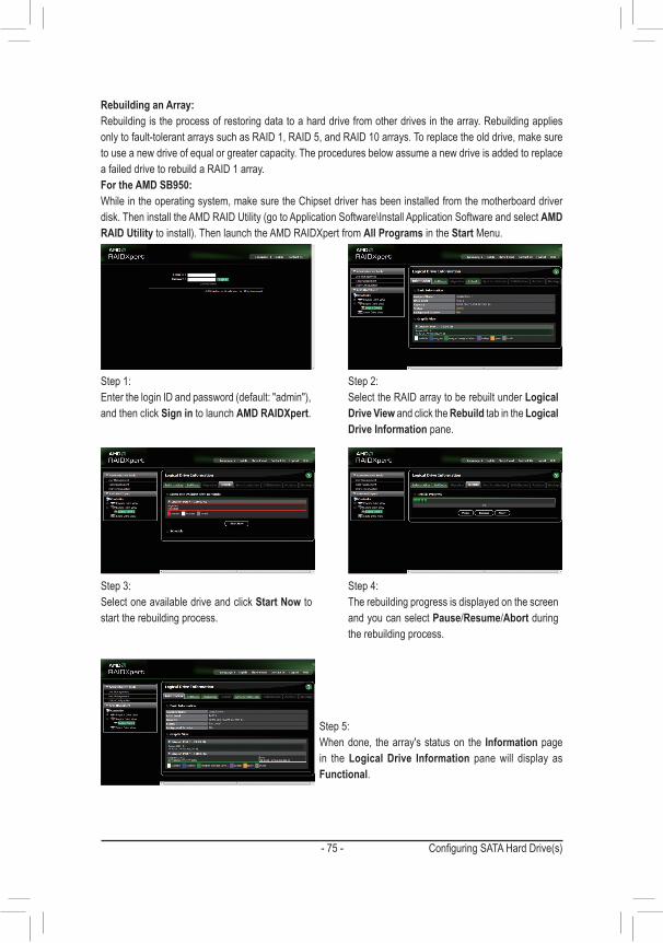
- 75 - Configuring SATA Hard Drive(s)
Rebuilding an Array:Rebuilding is the process of restoring data to a hard drive from other drives in the array. Rebuilding applies only to fault-tolerant arrays such as RAID 1, RAID 5, and RAID 10 arrays. To replace the old drive, make sure to use a new drive of equal or greater capacity. The procedures below assume a new drive is added to replace a failed drive to rebuild a RAID 1 array.For the AMD SB950:While in the operating system, make sure the Chipset driver has been installed from the motherboard driver disk. Then install the AMD RAID Utility (go to Application Software\Install Application Software and select AMD RAID Utility to install). Then launch the AMD RAIDXpert from All Programs in the Start Menu.
Step 1:Enter the login ID and password (default: "admin"), and then click Sign in to launch AMD RAIDXpert.
Step 2:Select the RAID array to be rebuilt under Logical Drive View and click the Rebuild tab in the Logical Drive Information pane.
Step 3:Select one available drive and click Start Now to start the rebuilding process.
Step 4:The rebuilding progress is displayed on the screen and you can select Pause/Resume/Abort during the rebuilding process.
Step 5:When done, the array's status on the Information page in the Logical Drive Information pane will display as Functional.

Configuring SATA Hard Drive(s) - 76 -
Step 2: The new hard drive will be displayed on the screen. Press <Enter> or <Space> on the new hard drive to select it and then press <Enter> on NEXT. When prompted, press <Y> to confirm. The new hard drive is now set as a Spare drive.
For the Marvell® 88SE9172:
Turn off your computer and replace the failed hard drive with a new one. Restart your computer. To enable an automatic rebuild in the operating system, you have to set the new hard drive as a Spare drive in the RAID setup utility first.
• Enabling Automatic RebuildStep 1:When the message "Press <Ctrl>+<M> to enter BIOS Setup or <Space> to continue" appears, press <Ctrl> + <M> to enter the RAID setup utility. On the main screen, press <Enter> on the RAID tab and then press <Enter> on Spare Management.
ENTER/SPACE: Select, ESC: Back/Exit
[ Selection] [ Adapter] [ Devices]
Marvell BIOS Setup (c) 2009 Marvell Technology Group Ltd.
Create VDDelete VDWipe out disk
RAID Config
Spare Management
[ RAID ]
[ Selection] [ Adapter] [ Devices] [ RAID ]
Marvell BIOS Setup (c) 2009 Marvell Technology Group Ltd.
RAID Config
Port Disk Name Size Max Speed Status
NEXT
Spare Management
* S0 SATA: WDC WD800JD-22LSA0 76.3GB SATA 3Gb/s FREE
ENTER/SPACE: Select, ESC: Back/Exit
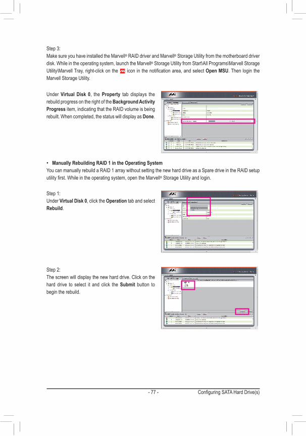
- 77 - Configuring SATA Hard Drive(s)
• Manually Rebuilding RAID 1 in the Operating SystemYou can manually rebuild a RAID 1 array without setting the new hard drive as a Spare drive in the RAID setup utility first. While in the operating system, open the Marvell® Storage Utility and login.
Under Virtual Disk 0, the Property tab displays the rebuild progress on the right of the Background Activity Progress item, indicating that the RAID volume is being rebuilt. When completed, the status will display as Done.
Step 1: Under Virtual Disk 0, click the Operation tab and select Rebuild.
Step 2: The screen will display the new hard drive. Click on the hard drive to select it and click the Submit button to begin the rebuild.
Step 3: Make sure you have installed the Marvell® RAID driver and Marvell® Storage Utility from the motherboard driver disk. While in the operating system, launch the Marvell® Storage Utility from Start\All Programs\Marvell Storage Utility\Marvell Tray, right-click on the icon in the notification area, and select Open MSU. Then login the Marvell Storage Utility.

Configuring SATA Hard Drive(s) - 78 -

- 79 - Drivers Installation
4-1 Installing Chipset Drivers
Chapter 4 Drivers Installation
After inserting the driver disk, "Xpress Install" will automatically scan your system and then list all the drivers that are recommended to install. You can click the Install All button and "Xpress Install" will install all the rec-ommended drivers. Or click Install Single Items to manually select the drivers you wish to install.
• Before installing the drivers, first install the operating system. • After installing the operating system, insert the motherboard driver disk into your optical drive.
The driver Autorun screen is automatically displayed which looks like that shown in the screen shot below. (If the driver Autorun screen does not appear automatically, go to My Computer, double-click the optical drive and execute the Run.exe program.)
• Please ignore the popup dialog box(es) (e.g. the Found New Hardware Wizard) displayed when "Xpress Install" is installing the drivers. Failure to do so may affect the driver installation.
• Some device drivers will restart your system automatically during the driver installation. After the system restart, "Xpress Install" will continue to install other drivers.
• After "Xpress Install" installs all of the drivers, a dialog box will appear asking whether to install new GIGABYTE utilities. Click Yes to automatically install the utilities. Or click No if you want to manually select the utilities to install on the Application Software page later.
• For USB 2.0 driver support under the Windows XP operating system, please install the Windows XP Service Pack 1 or later. After installing the SP1 (or later), if a question mark still exists in Universal Serial Bus Controller in Device Manager, please remove the question mark (by right-clicking your mouse and select Uninstall) and restart the system. (The system will then autodetect and install the USB 2.0 driver.)

Drivers Installation - 80 -
4-2 Application SoftwareThis page displays all the utilities and applications that GIGABYTE develops and some free software. You can click the Install button on the right of an item to install it.
4-3 Technical ManualsThis page provides the content descriptions for this driver disk.
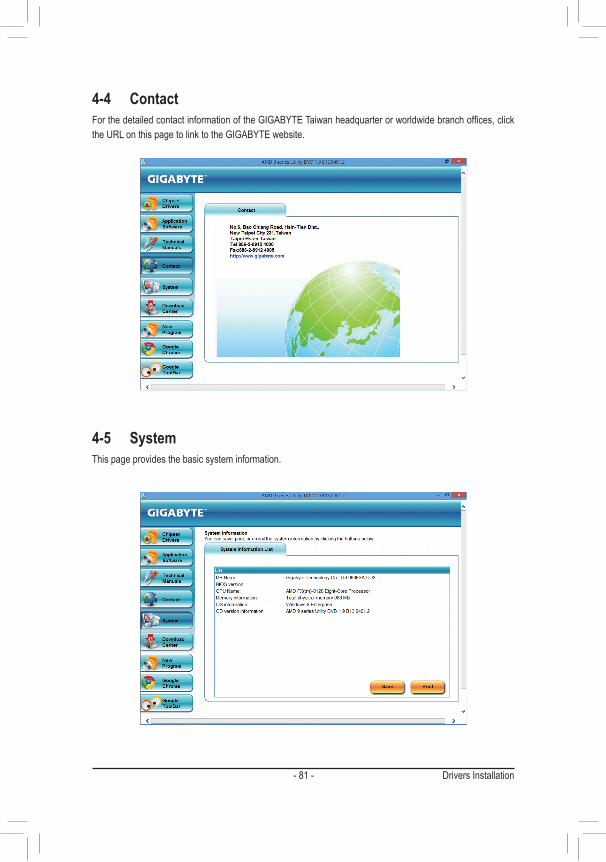
- 81 - Drivers Installation
4-4 ContactFor the detailed contact information of the GIGABYTE Taiwan headquarter or worldwide branch offices, click the URL on this page to link to the GIGABYTE website.
4-5 SystemThis page provides the basic system information.

Drivers Installation - 82 -
4-6 Download CenterTo update the BIOS, drivers, or applications, click the Download Center button to link to the GIGABYTE website. The latest version of the BIOS, drivers, or applications will be displayed.

- 83 - Unique Features
5-1-1 Updating the BIOS with the Q-Flash UtilityA. Before You Begin1. From GIGABYTE's website, download the latest compressed BIOS update file that matches your
motherboard model.2. Extract the file and save the new BIOS file (e.g. 9FXAUD34.F1) to your USB flash drive or hard drive. Note:
The USB flash drive or hard drive must use FAT32/16/12 file system. 3. Restart the system. During the POST, press the <End> key to enter Q-Flash. Note: You can access Q-Flash
by either pressing the <End> key during the POST or pressing the <F8> key in BIOS Setup. However, if the BIOS update file is saved to a hard drive in RAID/AHCI mode or a hard drive attached to an independent SATA controller, use the <End> key during the POST to access Q-Flash.
Because BIOS flashing is potentially risky, please do it with caution. Inadequate BIOS flashing may result in system malfunction.
Chapter 5 Unique Features5-1 BIOS Update Utilities
GIGABYTE motherboards provide two unique BIOS update tools, Q-Flash™ and @BIOS™. GIGABYTE Q-Flash and @BIOS are easy-to-use and allow you to update the BIOS without the need to enter MS-DOS mode. Additionally, this motherboard features the DualBIOS™ design, which enhances protection for the safety and stability of your computer by adding one more physical BIOS chip.
What is DualBIOS™?Motherboards that support DualBIOS have two BIOS onboard, a main BIOS and a backup BIOS. Normally, the system works on the main BIOS. However, if the main BIOS is corrupted or damaged, the backup BIOS will take over on the next system boot and copy the BIOS file to the main BIOS to ensure normal system operation. For the sake of system safety, users cannot update the backup BIOS manually.
What is Q-Flash™?With Q-Flash you can update the system BIOS without having to enter operating systems like MS-DOS or Window first. Embedded in the BIOS, the Q-Flash tool frees you from the hassles of going through complicated BIOS flashing process.
What is @BIOS™?@BIOS allows you to update the system BIOS while in the Windows environment. @BIOS will download the latest BIOS file from the nearest @BIOS server site and update the BIOS.

Unique Features - 84 -
B. Updating the BIOSIn the main menu of Q-Flash, use the keyboard or mouse to select an item to execute. When updating the BIOS, choose the location where the BIOS file is saved. The following procedure assumes that you save the BIOS file to a USB flash drive.
Step 1: 1. Insert the USB flash drive containing the BIOS file into the computer. In the main menu of Q-Flash, select
Update BIOS From Drive.
Step 2: The process of the system reading the BIOS file from the USB flash drive is displayed on the screen. When the message "Are you sure to update BIOS?" appears, select Yes to begin the BIOS update. The monitor will display the update process.
Step 3: When the update process is complete, select Reboot to reboot the system.
2. Select USB Flash Drive.
3. Select the BIOS update file.
• The Save BIOS to Drive option allows you to save the current BIOS file. • Q-Flash only supports USB flash drive or hard drives using FAT32/16/12 file system. • If the BIOS update file is saved to a hard drive in RAID/AHCI mode or a hard drive attached to
an independent SATA controller, use the <End> key during the POST to access Q-Flash.
Make sure the BIOS update file matches your motherboard model.
• Do not turn off or restart the system when the system is reading/updating the BIOS. • Do not remove the USB flash drive or hard drive when the system is updating the BIOS.
Q-Flash Utility v1.05Model Name : 990FXA-UD3BIOS Version : E14BIOS Date : 05/31/2013Flash Type/Size : MXIC 25L3206E 4MB
Update BIOS From DriveSave BIOS to Drive
Return to BIOS setupSelect Device
USB Flash Drive
Q-Flash
BIOS update is completed.
Power offReboot
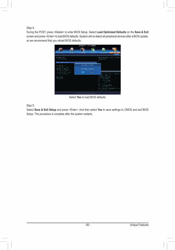
- 85 - Unique Features
Select Yes to load BIOS defaults
Step 4:During the POST, press <Delete> to enter BIOS Setup. Select Load Optimized Defaults on the Save & Exit screen and press <Enter> to load BIOS defaults. System will re-detect all peripheral devices after a BIOS update, so we recommend that you reload BIOS defaults.
Step 5:Select Save & Exit Setup and press <Enter>. And then select Yes to save settings to CMOS and exit BIOS Setup. The procedure is complete after the system restarts.

Unique Features - 86 -
5-1-2 Updating the BIOS with the @BIOS UtilityA. Before You Begin1. In Windows, close all applications and TSR (Terminate and Stay Resident) programs. This helps prevent
unexpected failures when performing a BIOS update.2. During the BIOS update process, ensure the Internet connection is stable and do NOT interrupt the Internet
connection (for example, avoid a power loss or switching off the Internet). Failure to do so may result in a corrupted BIOS or a system that is unable to start.
3. Do not use the G.O.M. (GIGABYTE Online Management) function when using @BIOS. 4. GIGABYTE product warranty does not cover any BIOS damage or system failure resulting from an
inadequate BIOS flashing.
B. Using @BIOS
Make sure that the BIOS file to be flashed matches your motherboard model. Updating the BIOS with an incorrect BIOS file could cause your system not to boot.
1. Update the BIOS Using the Internet Update Function: Click Update BIOS from GIGABYTE Server, select the @BIOS server site closest to your location and
then download the BIOS file that matches your motherboard model. Follow the on-screen instructions to complete.
2. Update the BIOS without Using the Internet Update Function: Click Update BIOS from File, then select the location where you save the BIOS update file obtained from
the Internet or through other source. Follow the on-screen instructions to complete.
3. Save the Current BIOS File: Click Save Current BIOS to File to save the current BIOS file.
4. Load BIOS Defaults after BIOS Update: Select the Load CMOS default after BIOS update check box and then the system will automatically load
BIOS defaults after BIOS update and after the system restarts.
C. After Updating the BIOSRestart your system after updating the BIOS.
If the BIOS update file for your motherboard is not present on the @BIOS server site, please manually download the BIOS update file from GIGABYTE's website and follow the instructions in "Update the BIOS without Using the Internet Update Function" below.
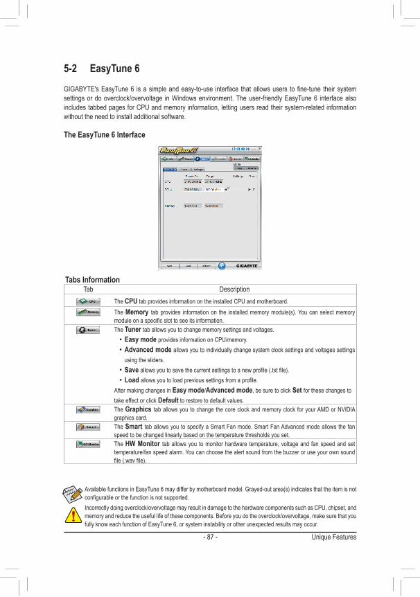
- 87 - Unique Features
Available functions in EasyTune 6 may differ by motherboard model. Grayed-out area(s) indicates that the item is not configurable or the function is not supported.Incorrectly doing overclock/overvoltage may result in damage to the hardware components such as CPU, chipset, and memory and reduce the useful life of these components. Before you do the overclock/overvoltage, make sure that you fully know each function of EasyTune 6, or system instability or other unexpected results may occur.
5-2 EasyTune 6GIGABYTE's EasyTune 6 is a simple and easy-to-use interface that allows users to fine-tune their system settings or do overclock/overvoltage in Windows environment. The user-friendly EasyTune 6 interface also includes tabbed pages for CPU and memory information, letting users read their system-related information without the need to install additional software.
The EasyTune 6 Interface
Tabs InformationTab Description
The CPU tab provides information on the installed CPU and motherboard.The Memory tab provides information on the installed memory module(s). You can select memory module on a specific slot to see its information.The Tuner tab allows you to change memory settings and voltages.
• Easy mode provides information on CPU/memory. • Advanced mode allows you to individually change system clock settings and voltages settings using the sliders.
• Save allows you to save the current settings to a new profile (.txt file). • Load allows you to load previous settings from a profile.
After making changes in Easy mode/Advanced mode, be sure to click Set for these changes to take effect or click Default to restore to default values.The Graphics tab allows you to change the core clock and memory clock for your AMD or NVIDIA graphics card.The Smart tab allows you to specify a Smart Fan mode. Smart Fan Advanced mode allows the fan speed to be changed linearly based on the temperature thresholds you set.The HW Monitor tab allows you to monitor hardware temperature, voltage and fan speed and set temperature/fan speed alarm. You can choose the alert sound from the buzzer or use your own sound file (.wav file).

Unique Features - 88 -
5-3 Smart Recovery 2
Smart Recovery 2 allows you to back up a partition as an image file every hour. You can use these images to restore your system or files when needed.
• Supported operating systems: Windows 8, 7 and Vista. • Smart Recovery 2 only supports NTFS file system. • You need to select the destination partition in Settings the first time
you use Smart Recovery 2. • The Backup Now button will be available only after you log in
Windows for ten minutes.
Creating a backup:Click the Settings button on the main menu. In the Settings dialog box, select the source partition and destination partition and click OK. The initial backup will start after 10 minutes and regular backup will be performed hourly. Note: By default, all partitions on the system drive are selected as the backup source. The backup destination cannot be on the same partition as the backup source.
Recovering a file:Click the File Recovery button on the main menu. Use the time slider on the top of the popped out window to select a previous backup time. The right pane will display the backed-up partitions in the backup destination (in the My Backup folder). Browse to the file you want and copy it.
The Smart Recovery 2 main menu:Button Description
Settings Allows you to select the source and destination partition
Backup Now Allows you to perform the backup immediatelyFile Recovery...
Allows you to recover your files from the backup image
System Recovery...
Allows you to recover your system from the backup image
Saving the the backup to a network location:If you want to save the backup to a network location, select Browse network location. Make sure your computer and the computer where you want to save the backup are in the same domain. Choose the network location where you want to store the backup and enter the user name and password. Follow the on-screen instructions to complete.

- 89 - Unique Features
Recovering your system with Smart Recovery 2 (Windows 8/7 only):Steps:1. Click the File Recovery button on the main menu.2. Select the location where your backup is saved.3. Use the time slider to select a time point.4. Select a partition backup created on the selected time point and
click Restore.5. Confirm whether to restart your system to proceed with the restore
immediately or later. Once you respond "Yes" the system will restart to the Windows recovery environment. Follow the onscreen instructions to restore your system.
Recovering your system using the original Windows installation disk:In case Windows or your hard drive has serious errors, use the original Windows installation disk for system recovery.Steps:1. Restart your computer to boot from the original Windows installation disk.2. When the Windows installation screen appears, select your language and click Next.3. Select Repair your computer.4. Select Restore your computer using a system image that you created earlier and then click Next.5. Select the backup you want to use and then follow the on-screen instructions to complete.
• For Windows Vista, refer to the steps below to use the original Windows installation disk for system recovery.
• All of your files and programs will be deleted and replaced with those on the selected backup. If needed, be sure to make a copy of your data before the restore.
For further instructions, refer to the Help file of Smart Recovery 2.

Unique Features - 90 -
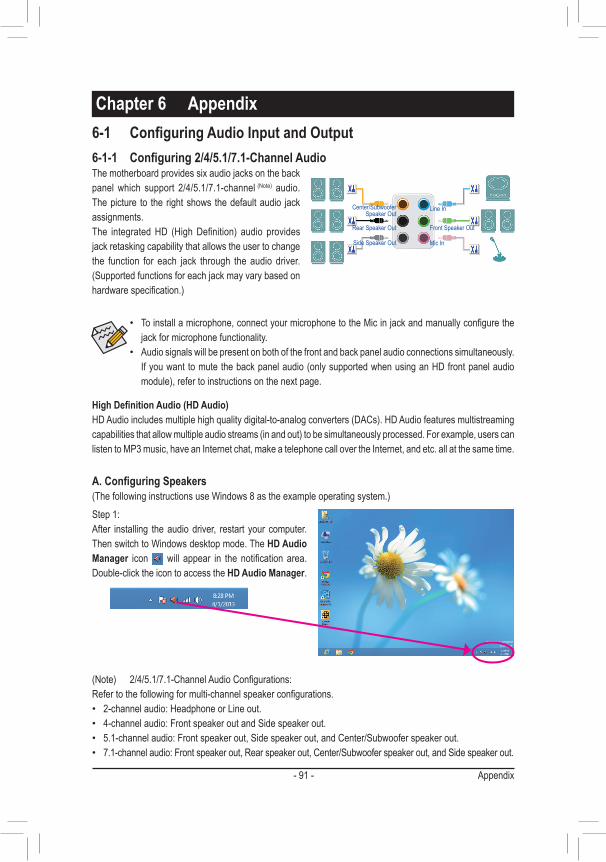
- 91 - Appendix
6-1-1 Configuring2/4/5.1/7.1-ChannelAudioThe motherboard provides six audio jacks on the back panel which support 2/4/5.1/7.1-channel (Note) audio. The picture to the right shows the default audio jack assignments. The integrated HD (High Definition) audio provides jack retasking capability that allows the user to change the function for each jack through the audio driver. (Supported functions for each jack may vary based on hardware specification.)
6-1 ConfiguringAudioInputandOutput
HighDefinitionAudio(HDAudio)HD Audio includes multiple high quality digital-to-analog converters (DACs). HD Audio features multistreaming capabilities that allow multiple audio streams (in and out) to be simultaneously processed. For example, users can listen to MP3 music, have an Internet chat, make a telephone call over the Internet, and etc. all at the same time.
A.ConfiguringSpeakers(The following instructions use Windows 8 as the example operating system.)
• To install a microphone, connect your microphone to the Mic in jack and manually configure the jack for microphone functionality.
• Audio signals will be present on both of the front and back panel audio connections simultaneously. If you want to mute the back panel audio (only supported when using an HD front panel audio module), refer to instructions on the next page.
Center/Subwoofer Speaker Out
Line In
Rear Speaker Out Front Speaker Out
Mic InSide Speaker Out
(Note) 2/4/5.1/7.1-Channel Audio Configurations:Refer to the following for multi-channel speaker configurations. • 2-channel audio: Headphone or Line out. • 4-channel audio: Front speaker out and Side speaker out. • 5.1-channel audio: Front speaker out, Side speaker out, and Center/Subwoofer speaker out. • 7.1-channel audio: Front speaker out, Rear speaker out, Center/Subwoofer speaker out, and Side speaker out.
Chapter6 Appendix
Step 1:After installing the audio driver, restart your computer. Then switch to Windows desktop mode. The HDAudioManager icon will appear in the notification area. Double-click the icon to access the HDAudioManager.

Appendix - 92 -
Step 2:Connect an audio device to an audio jack. The Thecurrentconnecteddeviceis dialog box appears. Select the device according to the type of device you connect. Then click OK.
Step 3:On the Speakers screen, click the SpeakerConfiguration tab. In the SpeakerConfiguration list, select Stereo, Quadraphonic, 5.1Speaker, or 7.1Speaker according to the type of speaker configuration you wish to set up. Then the speaker setup is completed.
If your chassis provides an AC'97 front panel audio module, to activate the AC'97 functionality, click the tool icon on the SpeakerConfiguration tab. On the ConnectorSettings dialog box, select the Disablefrontpaneljackdetection check box. Click OK to complete.
Click Deviceadvancedsettings on the top right corner on the SpeakerConfiguration tab to open the Deviceadvancedsettings dialog box. Select the Mutetherearoutputdevice,whenafrontheadphonepluggedin check box. Click OK to complete.
B.ConfiguringSoundEffectYou may configure an audio environment on the SoundEffects tab.
C.ActivatinganAC'97FrontPanelAudioModule
D.MutingtheBackPanelAudio(ForHDAudioOnly)

- 93 - Appendix
(Note) Enter the DigitalOutput(Optical) screen to configure further settings if you use the S/PDIF Out connector(s) on the back panel for digital audio output or enter the DigitalOutput screen if you use the internal S/PDIF Out connector (SPDIF_O) for digital audio output.
2.ConfiguringS/PDIFOut:On the DigitalOutput(Optical) screen (Note), click the DefaultFormat tab and then select the sample rate and bit depth. Click OK to complete.
The S/PDIF Out jack can transmit audio signals to an external decoder for decoding to get the best audio quality.
1.ConnectingaS/PDIFOutCable:Connect a S/PDIF optical cable to the corresponding S/PDIF out connector as shown below and an external decoder for transmitting the S/PDIF digital audio signals.
6-1-2 ConfiguringS/PDIFOut
Connects to a S/PDIF optical cable
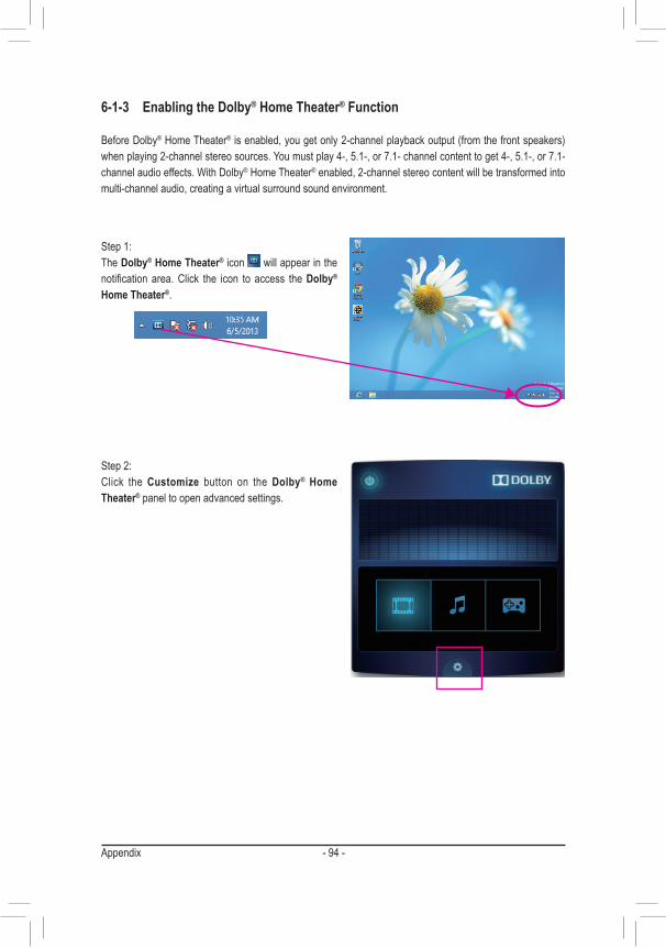
Appendix - 94 -
6-1-3 EnablingtheDolby®HomeTheater®Function
Before Dolby® Home Theater® is enabled, you get only 2-channel playback output (from the front speakers) when playing 2-channel stereo sources. You must play 4-, 5.1-, or 7.1- channel content to get 4-, 5.1-, or 7.1- channel audio effects. With Dolby® Home Theater® enabled, 2-channel stereo content will be transformed into multi-channel audio, creating a virtual surround sound environment.
Step 1:The Dolby®HomeTheater® icon will appear in the notification area. Click the icon to access the Dolby® HomeTheater®.
Step 2:Click the Customize button on the Dolby® HomeTheater® panel to open advanced settings.
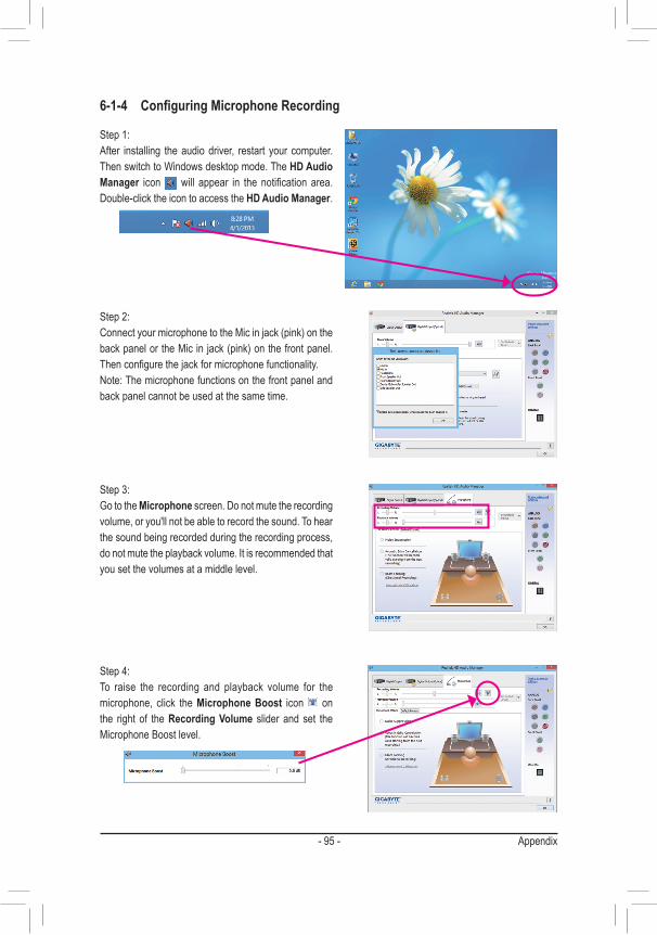
- 95 - Appendix
6-1-4 ConfiguringMicrophoneRecording
Step 2:Connect your microphone to the Mic in jack (pink) on the back panel or the Mic in jack (pink) on the front panel. Then configure the jack for microphone functionality. Note: The microphone functions on the front panel and back panel cannot be used at the same time.
Step 3:Go to the Microphone screen. Do not mute the recording volume, or you'll not be able to record the sound. To hear the sound being recorded during the recording process, do not mute the playback volume. It is recommended that you set the volumes at a middle level.
Step 1:After installing the audio driver, restart your computer. Then switch to Windows desktop mode. The HDAudioManager icon will appear in the notification area. Double-click the icon to access the HDAudioManager.
Step 4:To raise the recording and playback volume for the microphone, click the MicrophoneBoost icon on the right of the RecordingVolume slider and set the Microphone Boost level.

Appendix - 96 -
Step 5:To open the SoundRecorder, move the mouse cursor to the bottom left corner of the screen, click the Start icon to switch to the Start screen (or press the Windows button on the keyboard). Right-click on the screen and click the Allapps icon on the bottom right corner of the screen to access the Apps screen
Step 1:Locate the icon in the notification area and right-click on this icon. Select RecordingDevices.
*EnablingStereoMixIf the HD Audio Manager does not display the recording device you wish to use, refer to the steps below. The following steps explain how to enable Stereo Mix (which may be needed when you want to record sound from your computer).
Step 6:On this screen, click SoundRecorder for audio recording.
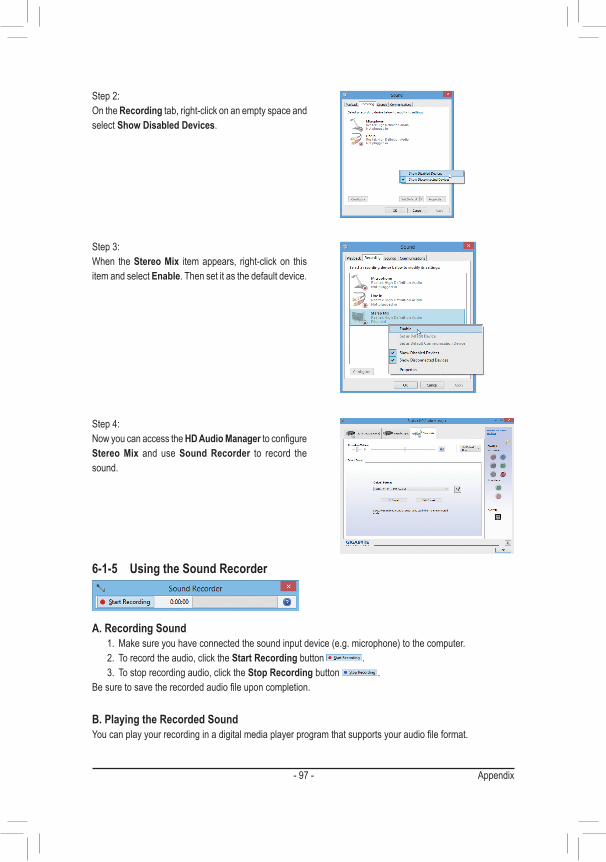
- 97 - Appendix
6-1-5 UsingtheSoundRecorder
A.RecordingSound1. Make sure you have connected the sound input device (e.g. microphone) to the computer.2. To record the audio, click the StartRecording button .3. To stop recording audio, click the StopRecording button .
Be sure to save the recorded audio file upon completion.
B.PlayingtheRecordedSoundYou can play your recording in a digital media player program that supports your audio file format.
Step 4:Now you can access the HDAudioManager to configure StereoMix and use SoundRecorder to record the sound.
Step 2:On the Recording tab, right-click on an empty space and select ShowDisabledDevices.
Step 3:When the StereoMix item appears, right-click on this item and select Enable. Then set it as the default device.

Appendix - 98 -
6-2 Troubleshooting
6-2-1 FrequentlyAskedQuestionsTo read more FAQs for your motherboard, please go to the Support&Downloads\FAQ page on GIGABYTE's website.
Q: Why is the light of my keyboard/optical mouse still on after the computer shuts down?A: Some motherboards provide a small amount of standby power after the computer shuts down and that's why the light is
still on.
Q: How do I clear the CMOS values?A: For motherboards that have a Clear CMOS button, press this button to clear the CMOS values (before doing this, please
turn off the computer and unplug the power cord). For motherboards that have a Clear CMOS jumper, refer to the instruc-tions in Chapter 1 to short the jumper to clear the CMOS values. If your board doesn't have this jumper/button, refer to the instructions on the motherboard battery in Chapter 1. You can temporarily remove the battery from the battery holder to stop supplying power to the CMOS, which will clear the CMOS values after about one minute.
Q: Why do I still get a weak sound even though I have turned my speaker to the maximum volume?A: Make sure your speaker is equipped with an internal amplifier. If not, try a speaker with power/amplifier.
Q: Why cannot I install the onboard HD audio driver successfully? (For Windows XP only)A: Step 1: First, make sure Service Pack 1 or Service Pack 2 has been installed (check in My Computer > Properties > Gen-
eral > System). If not, please update it from Microsoft's website. Then make sure the Microsoft UAA Bus Driver for High Definition Audio has been installed successfully (check in My Computer > Properties > Hardware > Device Manager > System Devices).
Step 2: Check if AudioDeviceonHighDefinitionAudioBus or Unknowndevice is present in DeviceManager or Sound,video,andgamecontrollers. If yes, please disable this device. (If not, skip this step.)
Step 3: Then go back to My Computer > Properties > Hardware > Device Manager > System devices and right-click on MicrosoftUAABusDriverforHighDefinitionAudio and select Disable and Uninstall.
Step 4: In DeviceManager, right-click on the computer name and select Scanforhardwarechanges. When the AddNewHardwareWizard appears, click Cancel. Then install the onboard HD audio driver from the motherboard driver disk or download the audio driver from GIGABYTE's website to install.
For more details, go to the Support&Downloads\FAQ page on our website and search for "onboard HD audio driver."

- 99 - Appendix
6-2-2 TroubleshootingProcedure
If you encounter any troubles during system startup, follow the troubleshooting procedure below to solve the problem.
START
A
Turn off the power. Remove all peripherals, connecting cables, and power cord etc.
Isolate the short circuit.
Secure the CPU cooler on the CPU. Connect the CPU cooler power cable to the motherboard.
Correctly insert the memory into the memory socket.
(Continued...)
Yes
The problem is verified and solved.
The problem is verified and solved.
The problem is verified and solved.
No
No
No
Yes
Yes
Insert the graphics card. Connect the ATX main power cable and the 12V power cable. Turn on the power to start the computer.
Make sure the motherboard does not short-circuit with the chassis or other metal objects.
Check if the CPU cooler is attached to the CPU securely. Is the pow-er connector of the CPU cooler connected to the CPU_FAN header properly?
Check if the memory is installed properly on the memory slot.
Make sure the graphics card is securely seated in the expansion slot and power connectors are firmly attached.

Appendix - 100 -
If the procedure above is unable to solve your problem, contact the place of purchase or local dealer for help. Or go to the Support&Downloads\TechnicalSupport page to submit your question. Our customer service staff will reply you as soon as possible.
The power supply, CPU or CPU socket might fail.
The keyboard or keyboard connector might fail.
END
A
Turn off the computer. Plug in the keyboard and mouse and restart the computer.
The graphics card, expansion slot, or monitor might fail.
The hard drive, connector, or cable might fail.
No
The problem is verified and solved.
The problem is verified and solved.
The problem is verified and solved.
No
No
Yes
Yes
Yes
Reinstall the operating system. Reinstall other devices one by one (install one device at one time and then boot the system to see if the device works successfully).
Press <Delete> to enter BIOS Setup. Select "Load Optimized De-faults." Select "Save & Exit Setup" to save changes and exit BIOS Setup.
Check if there is display on your monitor.
When the computer is turned on, is the CPU cooler running?
Check if the keyboard is working properly.
No
The problem is verified and solved.Yes
Turn off the computer and connect the hard drive(s). Check if the system can boot successfully.
- 101 - Appendix
RegulatoryStatementsRegulatoryNoticesThis document must not be copied without our written permission, and the contents there of must not be imparted to a third party nor be used for any unauthorized purpose. Contravention will be prosecuted. We believe that the information contained herein was accurate in all respects at the time of printing. GIGABYTE cannot, however, assume any responsibility for errors or omissions in this text. Also note that the information in this document is subject to change without notice and should not be construed as a commitment by GIGABYTE.
OurCommitmenttoPreservingtheEnvironmentIn addition to high-efficiency performance, all GIGABYTE motherboards fulfill European Union regulations for RoHS (Restriction of Certain Hazardous Substances in Electrical and Electronic Equipment) and WEEE (Waste Electrical and Electronic Equipment) environmental directives, as well as most major worldwide safety requirements. To prevent releases of harmful substances into the environment and to maximize the use of our natural resources, GIGABYTE provides the following information on how you can responsibly recycle or reuse most of the materials in your "end of life" product.
RestrictionofHazardousSubstances(RoHS)DirectiveStatementGIGABYTE products have not intended to add and safe from hazardous substances (Cd, Pb, Hg, Cr+6, PBDE and PBB). The parts and components have been carefully selected to meet RoHS requirement. Moreover, we at GIGABYTE are continuing our efforts to develop products that do not use internationally banned toxic chemicals.
WasteElectrical&ElectronicEquipment(WEEE)DirectiveStatementGIGABYTE will fulfill the national laws as interpreted from the 2002/96/EC WEEE (Waste Electrical and Electronic Equipment) directive. The WEEE Directive specifies the treatment, collection, recycling and disposal of electric and electronic devices and their components. Under the Directive, used equipment must be marked, collected separately, and disposed of properly.
WEEESymbolStatementThe symbol shown below is on the product or on its packaging, which indicates that this product must not be disposed of with other waste. Instead, the device should be taken to the waste collection centers for activation of the treatment, collection, recycling and disposal procedure. The separate collection and recycling of your waste equipment at the time of disposal will help to conserve natural resources and ensure that it is recycled in a manner that protects human health and the environment.
For more information about where you can drop off your waste equipment for recycling, please contact your local government office, your household waste disposal service or where you purchased the product for details of environmentally safe recycling.
� When your electrical or electronic equipment is no longer useful to you, "take it back" to your local or regional waste collection administration for recycling.
� If you need further assistance in recycling, reusing in your "end of life" product, you may contact us at the Customer Care number listed in your product's user's manual and we will be glad to help you with your effort.
Finally, we suggest that you practice other environmentally friendly actions by understanding and using the energy-saving features of this product (where applicable), recycling the inner and outer packaging (including shipping containers) this product was delivered in, and by disposing of or recycling used batteries properly. With your help, we can reduce the amount of natural resources needed to produce electrical and electronic equipment, minimize the use of landfills for the disposal of "end of life" products, and generally improve our quality of life by ensuring that potentially hazardous substances are not released into the environment and are disposed of properly.

Appendix - 102 -
- 103 - Appendix
ContactUs
• GIGA-BYTETECHNOLOGYCO.,LTD.Address: No.6, Bao Chiang Road, Hsin-Tien Dist.,New Taipei City 231,TaiwanTEL: +886-2-8912-4000FAX: +886-2-8912-4005Tech. and Non-Tech. Support (Sales/Marketing) :http://ggts.gigabyte.com.twWEB address (English): http://www.gigabyte.comWEB address (Chinese): http://www.gigabyte.tw • G.B.T.INC.-U.S.A.
TEL: +1-626-854-9338FAX: +1-626-854-9326Tech. Support: http://ggts.gigabyte.com.twWarranty Info: http://rma.gigabyte.usWeb address: http://www.gigabyte.us • G.B.T.INC(USA)-Mexico
Tel: +1-626-854-9338 x 215 (Soporte de habla hispano)FAX: +1-626-854-9326Correo: [email protected]. Support: http://rma.gigabyte.usWeb address: http://latam.giga-byte.com • Giga-ByteSINGAPOREPTE.LTD.-Singapore
WEB address : http://www.gigabyte.sg • Thailand
WEB address : http://th.giga-byte.com • Vietnam
WEB address : http://www.gigabyte.vn
• NINGBOG.B.T.TECH.TRADINGCO.,LTD.-ChinaWEB address : http://www.gigabyte.cnShanghaiTEL: +86-21-63400912FAX: +86-21-63400682BeijingTEL: +86-10-62102838FAX: +86-10-62102848WuhanTEL: +86-27-87685981FAX: +86-27-87579461GuangZhouTEL: +86-20-87540700FAX: +86-20-87544306ChengduTEL: +86-28-85483135FAX: +86-28-85256822XianTEL: +86-29-85531943FAX: +86-29-85510930ShenyangTEL: +86-24-83992342FAX: +86-24-83992102 • GIGABYTETECHNOLOGY(INDIA)LIMITED-India
WEB address : http://www.gigabyte.in • SaudiArabia
WEB address : http://www.gigabyte.com.sa • GigabyteTechnologyPty.Ltd.-Australia
WEB address : http://www.gigabyte.com.au

Appendix - 104 -
• GIGABYTEGlobalServiceSystem
To submit a technical or non-technical (Sales/Marketing) question, please link to:http://ggts.gigabyte.com.twThen select your language to enter the system.
• G.B.T.TECHNOLOGYTRADINGGMBH-GermanyWEB address : http://www.gigabyte.de • G.B.T.TECH.CO.,LTD.-U.K.
WEB address : http://www.giga-byte.co.uk • Giga-ByteTechnologyB.V.-TheNetherlands
WEB address : http://www.giga-byte.nl • GIGABYTETECHNOLOGYFRANCE-France
WEB address : http://www.gigabyte.fr • Sweden
WEB address : http://www.gigabyte.se • Italy
WEB address : http://www.giga-byte.it • Spain
WEB address : http://www.giga-byte.es • Greece
WEB address : http://www.gigabyte.com.gr • CzechRepublic
WEB address : http://www.gigabyte.cz
• HungaryWEB address : http://www.giga-byte.hu • Turkey
WEB address : http://www.gigabyte.com.tr • Russia
WEB address : http://www.gigabyte.ru • Poland
WEB address : http://www.gigabyte.pl • Ukraine
WEB address : http://www.gigabyte.ua • Romania
WEB address : http://www.gigabyte.com.ro • Serbia
WEB address : http://www.gigabyte.co.rs • Kazakhstan
WEB address : http://www.gigabyte.kz
You may go to the GIGABYTE website, select your language in the language list on the top right corner of the website.