mbe/mbr goodman manufacturing company, l.p. © 2004-2009
TRANSCRIPT

THIS PRODUCT CONTAINS ELECTRONIC COMPONENTS WHICH REQUIRE ADEFINITE GROUND. PROVISIONS ARE MADE FOR CONNECTION OF THEGROUND. A DEDICATED GROUND FROM THE MAIN POWER SUPPLY ORAN EARTH GROUND MUST BE PROVIDED.
INTRODUCTIONThis booklet contains the installation and operating instruc-tions for your modular blower cabinet. All warnings and pre-cautions within this booklet must be observed. Improper in-stallation can result in unsatisfactory operation or dangerousconditions and void the warranty. Read this booklet and anyinstructions packaged with accessories prior to installation.Give this booklet to the user and explain its provisions. Theuser should retain this booklet for future reference.CHECKING PRODUCT RECEIVEDUpon receiving the unit, inspect it for damage from shipment.Claims for damage, either shipping or concealed, should befiled immediately with the shipping company. Check the unitmodel number, specifications, electrical characteristics andaccessories to determine if they are correct. In the event anincorrect unit is shipped, it must be returned to the supplierand must NOT be installed. The manufacturer assumes noresponsibility for installation of incorrectly shipped units.REPLACEMENT PARTSORDERING PARTSWhen reporting shortages or damages, or ordering repair parts,give the complete unit model and serial numbers as stampedon the unit’s nameplate.Replacement parts for this appliance are available through yourcontractor or local distributor. For the location of your nearestdistributor, consult the white business pages, the yellow pagesection of the local telephone book or contact:
CONSUMER AFFAIRSGOODMAN MANUFACTURING COMPANY, L.P.
7401 SECURITY WAYHOUSTON, TEXAS 77040
(877) 254-4729
IMPORTANT SAFETY INSTRUCTIONSRECOGNIZE SAFETY SYMBOLS, WORDS, AND LABELSThe following symbols and labels are used throughout thismanual to indicate immediate or potential hazards. It is theowner’s responsibility to read and comply with all safety infor-mation and instructions accompanying these symbols. Fail-ure to heed safety information increases the risk of propertydamage, product damage, personal injury or death.
HIGH VOLTAGE! Disconnect ALL power before servicing.Multiple power sources may be present.Failure to do so may cause property damage,personal injury or death.
MBE/MBRBLOWER CABINETINSTALLATION INSTRUCTIONS
Goodman Manufacturing Company, L.P. © 2004-2009, 20115151 San Felipe, Suite 500, Houston, TX 77056www.goodmanmfg.com -or- www.amana-hac.comP/N: IO-239F Date: June 2011
CARBON MONOXIDE POISONING HAZARD
-
Special Warning for Installation of Furnace or Air Handling Units inEnclosed Areas such as Garages, Utility Rooms or Parking Areas
Carbon monoxide producing devices (such as an automobile, spaceheater, gas water heater, etc.) should not be operated in enclosed areassuch as unventilated garages, utility rooms or parking areas because ofthe danger of carbon monoxide (CO) poisoning resulting from the exhaustemissions. If a furnace or air handler is installed in an enclosed area suchas a garage, utility room or parking area and a carbon monoxide producingdevice is operated therein, there must be adequate, direct outsideventilation.
This ventilation is necessary to avoid the danger of CO poisoning whichcan occur if a carbon monoxide producing device continues to operate inthe enclosed area. Carbon monoxide emissions can be (re)circulatedthroughout the structure if the furnace or air handler is operating in anymode.
CO can cause serious illness including permanent brain damage or death.
B10259-216
GENERAL INFORMATIONThe MBR/MBE Blower Cabinets are used in combination witha cased evaporator coil. This combination of blower and coilfunctions as the indoor part of a split air-conditioning system,and may be matched with a remote condensing or heat pumpunit. The blower cabinet can also function as an electric fur-nace when used with an electric heater.NOTE: The electric heating elements for electric furnace in-stallation are not shipped with the cabinet and are field-installed.Systems should be properly sized by heat gain and loss cal-culations made according to methods of the Air ConditioningContractors Association (ACCA) or equivalent. It is thecontractor’s responsibility to ensure the system has adequatecapacity to heat or cool the conditioned space.
2
INTRODUCTION ............................................................................................................................................1CHECKING PRODUCT RECEIVED ..............................................................................................................1REPLACEMENT PARTS ................................................................................................................................1
ORDERING PARTS ......................................................................................................................................................................... 1
IMPORTANT SAFETY INSTRUCTIONS.......................................................................................................1RECOGNIZE SAFETY SYMBOLS, WORDS, AND LABELS ............................................................................................................ 1
GENERAL INFORMATION ............................................................................................................................1CLEARANCES AND ACCESSIBILITY ............................................................................................................................................ 3INSULATION .................................................................................................................................................................................. 3
INSTALLATION INSTRUCTIONS..................................................................................................................3BLOWER WITH CASED EVAPORATOR COIL INSTALLATION ..................................................................................................... 3UPFLOW INSTALLATION .............................................................................................................................................................. 3COUNTERFLOW INSTALLATION .................................................................................................................................................. 3HORIZONTAL INSTALLATION ....................................................................................................................................................... 4
ELECTRICAL CONNECTIONS .....................................................................................................................4HIGH VOLTAGE WIRING ................................................................................................................................................................ 4LOW VOLTAGE WIRING ................................................................................................................................................................ 5MISCELLANEOUS ELECTRICAL ................................................................................................................................................... 5THERMOSTAT CONNECTIONS ..................................................................................................................................................... 5MBE MOTOR ................................................................................................................................................................................. 5MOTOR SPEED ADJUSTMENT ..................................................................................................................................................... 5DIPSWITCH FUNCTIONS .............................................................................................................................................................. 5CFM DELIVERY .............................................................................................................................................................................. 5THERMOSTAT “FAN ONLY” MODE ............................................................................................................................................... 6CFM TRIM ADJUST ....................................................................................................................................................................... 6HUMIDITY CONTROL ..................................................................................................................................................................... 6TWO STAGE HEATING ................................................................................................................................................................... 6THERMOSTAT WIRING .................................................................................................................................................................. 6MBR MOTOR ................................................................................................................................................................................. 6BLOWER PERFORMANCE DATA .................................................................................................................................................. 6
SINGLE STAGE COOLING WITH SINGLE OR TWO STAGE HEATING ...................................................9HEAT PUMP WITH SINGLE OR TWO-STAGE HEATING (OPTIONS FOR EMERGENCY HEAT) ........10TWO-STAGE COOLING WITH CONVENTIONAL TWO-STAGE THERMOSTAT ....................................13HEAT PUMP WITH SINGLE OR TWO STAGE HEATING WITH CONVENTIONAL THERMOSTAT
(OPTIONS FOR EMERGENCY HEAT) .................................................................................................152 SPEED HEAT PUMP WITH SINGLE OR TWO-STAGE HEATING
(OPTIONS FOR EMERGENCY HEAT) WITH CONVENTIONAL TWO-STAGE THERMOSTAT.......17TWO STAGE COOLING WITH CONVENTIONAL TWO STAGE THERMOSTAT
(ENCLOSED WITH ADD ON 1N006 DIODES) ......................................................................................20TSTWK01 KIT REQUIRED ..........................................................................................................................20ENCODED TWO STAGE COOLING
WITH GMC THERMOSTAT PART #CHET18-60 TSTWKO1 KIT REQUIRED .....................................21TROUBLESHOOTING ENCODED TWO STAGE COOLING THERMOSTATS OPTIONS ....................22WIRING DIAGRAM ........................................................................................................................................24

3
CLEARANCES AND ACCESSIBILITYThe unit can be positioned for upflow, counterflow, horizontalright or horizontal left operation. Zero clearance is allowed onall sides for combustible materials. Thirty-six inches should beallotted on the door side for maintenance and service.To reduce risk of rusting, do not install the unit blower directlyon the ground or on a floor that is likely to be wet. In suchenvironments, the unit must be elevated by use of a sturdy,nonporous material.
INSULATIONTo ensure efficient operation, review the following precautions.
• If the unit is located in an area with high ambient tem-perature and/or high humidity, the air handler may besubject to nuisance sweating of the casing. On theseinstallations, a wrap of 2” fiberglass insulation with avapor barrier is recommended.
• The factory recommends insulating the duct runningthrough any unconditioned spaces.
To reduce operating sound and vibration transmission use flex-ible canvas duct connections at the cabinet.INSTALLATION INSTRUCTIONSBLOWER WITH CASED EVAPORATOR COILINSTALLATION
TOP CABINET
BOTTOM CABINET
Figure 1Secure the coil and blower together with the two connectorplates and screws supplied in the blower bag assembly. Useone connector plate and six screws on each side of the unit.If accessory electric heat is to be added, install now per theinstructions shipped with the heater kit.
UPFLOW INSTALLATIONFor upflow installations, the blower cabinet must sit on top ofthe coil cabinet (Figure 2). NOTE: All panels should be inplace before installing the cabinet.
1. Place the blower and coil cabinet assembly upright onthe return duct or duct opening. Ensure that there isample support for the cabinet assembly and all attachedductwork.
2. Connect refrigerant and condensate drain connections perthe evaporator coil installation instructions. Ensure re-frigerant and drain lines do not interfere with service ac-cess to the unit.
3. Attach supply ductwork. Seal connections between unitand ductwork as required to reduce/eliminate air leak-age.
4. Make electrical connections as specified in “Electrical”section of this manual.
Air Flow
Figure 2 - Upflow ApplicationCOUNTERFLOW INSTALLATIONFor counterflow installations, the evaporator coil cabinet mustsit on top of the blower cabinet (Figure 3). NOTE: All panelsshould be in place when installing the unit.
Air Flow
figure 3 - Counterflow ApplicationNOTE: Supply ductwork for counterflow applications, must beClass I. However, if combustible ductwork is used, sheet metalprotection is required.
1. Place the blower and coil cabinet assembly supply outleton the supply duct or duct opening. Ensure there is amplesupport for the unit and all attached ductwork.
2. Connect refrigerant and condensate drain connections perthe evaporator coil installation instructions. Ensure re-frigerant and drain lines do not interfere with service ac-cess to the unit.
3. Attach return ductwork. Seal connections between unitand ductwork as required to reduce/eliminate air leak-age.
4. Make electrical connections as specified in “Electrical”section of this manual.
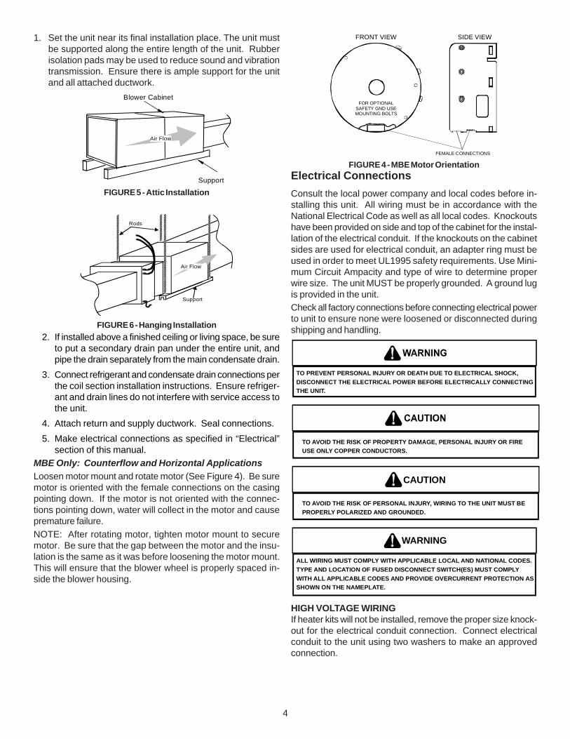
HORIZONTAL INSTALLATIONFor horizontal installations, the coil cabinet must be upstreamof the blower cabinet (Figures 5 and 6). NOTE: All panelsshould be in place when installing the unit.
4
1. Set the unit near its final installation place. The unit mustbe supported along the entire length of the unit. Rubberisolation pads may be used to reduce sound and vibrationtransmission. Ensure there is ample support for the unitand all attached ductwork.
Air Flow
Blower Cabinet
Support
FIGURE 5 - Attic Installation
Air Flow
Rods
Support
FIGURE 6 - Hanging Installation2. If installed above a finished ceiling or living space, be sure
to put a secondary drain pan under the entire unit, andpipe the drain separately from the main condensate drain.
3. Connect refrigerant and condensate drain connections perthe coil section installation instructions. Ensure refriger-ant and drain lines do not interfere with service access tothe unit.
4. Attach return and supply ductwork. Seal connections.5. Make electrical connections as specified in “Electrical”
section of this manual.MBE Only: Counterflow and Horizontal ApplicationsLoosen motor mount and rotate motor (See Figure 4). Be suremotor is oriented with the female connections on the casingpointing down. If the motor is not oriented with the connec-tions pointing down, water will collect in the motor and causepremature failure.NOTE: After rotating motor, tighten motor mount to securemotor. Be sure that the gap between the motor and the insu-lation is the same as it was before loosening the motor mount.This will ensure that the blower wheel is properly spaced in-side the blower housing.
FRONT VIEW
FOR OPTIONAL SAFETY GND USEMOUNTING BOLTS
SIDE VIEW
FEMALE CONNECTIONS
FIGURE 4 - MBE Motor OrientationElectrical ConnectionsConsult the local power company and local codes before in-stalling this unit. All wiring must be in accordance with theNational Electrical Code as well as all local codes. Knockoutshave been provided on side and top of the cabinet for the instal-lation of the electrical conduit. If the knockouts on the cabinetsides are used for electrical conduit, an adapter ring must beused in order to meet UL1995 safety requirements. Use Mini-mum Circuit Ampacity and type of wire to determine properwire size. The unit MUST be properly grounded. A ground lugis provided in the unit.Check all factory connections before connecting electrical powerto unit to ensure none were loosened or disconnected duringshipping and handling.
TO PREVENT PERSONAL INJURY OR DEATH DUE TO ELECTRICAL SHOCK,DISCONNECT THE ELECTRICAL POWER BEFORE ELECTRICALLY CONNECTINGTHE UNIT.
TO AVOID THE RISK OF PROPERTY DAMAGE, PERSONAL INJURY OR FIREUSE ONLY COPPER CONDUCTORS.
TO AVOID THE RISK OF PERSONAL INJURY, WIRING TO THE UNIT MUST BEPROPERLY POLARIZED AND GROUNDED.
CAUTION
ALL WIRING MUST COMPLY WITH APPLICABLE LOCAL AND NATIONAL CODES.TYPE AND LOCATION OF FUSED DISCONNECT SWITCH(ES) MUST COMPLYWITH ALL APPLICABLE CODES AND PROVIDE OVERCURRENT PROTECTION ASSHOWN ON THE NAMEPLATE.
WARNING
HIGH VOLTAGE WIRINGIf heater kits will not be installed, remove the proper size knock-out for the electrical conduit connection. Connect electricalconduit to the unit using two washers to make an approvedconnection.
5
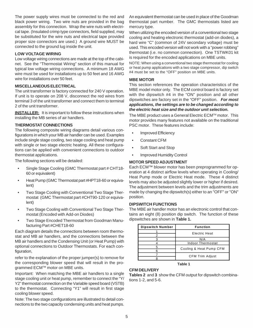
The power supply wires must be connected to the red andblack power wiring. Two wire nuts are provided in the bagassembly for this connection. Wrap the wire nuts with electri-cal tape. (Insulated crimp type connectors, field supplied, maybe substituted for the wire nuts and electrical tape providedproper size connectors are used.) A ground wire MUST beconnected to the ground lug inside the unit.
LOW VOLTAGE WIRINGLow voltage wiring connections are made at the top of the cabi-net. See the “Thermostat Wiring” section of this manual fortypical low voltage wiring connections. A minimum 18 AWGwire must be used for installations up to 50 feet and 16 AWGwire for installations over 50 feet.
MISCELLANEOUS ELECTRICALThe unit transformer is factory connected for 240 V operation.If unit is to operate on 208 V, disconnect the red wires fromterminal 3 of the unit transformer and connect them to terminal2 of the unit transformer.INSTALLER: It is important to follow these instructions wheninstalling the MB series of air handlers.
THERMOSTAT CONNECTIONSThe following composite wiring diagrams detail various con-figurations in which your MB air handler can be used. Examplesinclude single stage cooling, two stage cooling and heat pumpwith single or two stage electric heating. All these configura-tions can be applied with convenient connections to outdoorthermostat applications.The following sections will be detailed:
• Single Stage Cooling (GMC Thermostat part # CHT18-60 or equivalent)
• Heat Pump (GMC Thermostat part #HPT18-60 or equiva-lent)
• Two Stage Cooling with Conventional Two Stage Ther-mostat (GMC Thermostat part #CHT90-120 or equiva-lent)
• Two Stage Cooling with Conventional Two Stage Ther-mostat (Encoded with Add-on Diodes)
• Two Stage Encoded Thermostat from Goodman Manu-facturing Part #CHET18-60
Each diagram details the connections between room thermo-stat and MB air handlers, and the connections between theMB air handlers and the Condensing Unit (or Heat Pump) withoptional connections to Outdoor Thermostats. For each con-figuration,refer to the explanation of the proper jumper(s) to remove forthe corresponding blower speed that will result in the pro-grammed ECMTM motor on MBE units.Important: When matching the MBE air handlers to a singlestage cooling unit or heat pump, remember to connect the “Y/Y2” thermostat connection on the Variable speed board (VSTB)to the thermostat. Connecting “Y1” will result in first stagecooling blower speed.Note: The two stage configurations are illustrated to detail con-nections to the two capacity condensing units and heat pumps.
An equivalent thermostat can be used in place of the Goodmanthermostat part number. The GMC thermostats listed aremercury type.When utilizing the encoded version of a conventional two stagecooling and heating electronic thermostat (add-on diodes), ahard wire “C” (common of 24V secondary voltage) must beused. This encoded version will not work with a “power robbing”thermostat (i.e. no common connection). One TSTWK01 kitis required for the encoded applications on MBE units.NOTE: When using a conventional two stage thermostat for coolingor heat pump applications with a two stage compressor, dip switch#4 must be set to the “OFF” position on MBE units.
MBE MOTORThis section references the operation characteristics of theMBE model motor only. The ECM control board is factory setwith the dipswitch #4 in the “ON” position and all otherdipswitches are factory set in the “OFF” position. For mostapplications, the settings are to be changed according tothe electric heat size and the outdoor unit selection.The MBE product uses a General Electric ECMTM motor. Thismotor provides many features not available on the traditionalPSC motor. These features include:
• Improved Efficiency
• Constant CFM
• Soft Start and Stop
• Improved Humidity Control
MOTOR SPEED ADJUSTMENTEach ECM™ blower motor has been preprogrammed for op-eration at 4 distinct airflow levels when operating in Cooling/Heat Pump mode or Electric Heat mode. These 4 distinctlevels may also be adjusted slightly lower or higher if desired.The adjustment between levels and the trim adjustments aremade by changing the dipswitch(s) either to an "OFF" or "ON"position.
DIPSWITCH FUNCTIONSThe MBE air handler motor has an electronic control that con-tains an eight (8) position dip switch. The function of thesedipswitches are shown in Table 1.
Dipswitch Number Function123 N/A4 Indoor Thermostat5678
Cooling & Heat Pump CFM
CFM Trim Adjust
Electric Heat
Table 1CFM DELIVERYTables 2 and 3 show the CFM output for dipswitch combina-tions 1-2, and 5-6.

6
Model Switch 1 Switch 2 Electric Heat CFMOFF OFF 1200ON OFF 1000OFF ON 800ON ON 600OFF OFF 1600ON OFF 1400OFF ON 1200ON ON 1000OFF OFF 1900ON OFF 1600OFF ON 1400ON ON 1200
MBE1600
MBE2000
MBE1200
Table 2Model Switch 5 Switch 6 Cooling/HP CFM
OFF OFF 1200ON OFF 1000OFF ON 800ON ON 600OFF OFF 1600ON OFF 1400OFF ON 1200ON ON 1000OFF OFF 2000ON OFF 1800OFF ON 1600ON ON 1200
MBE1200
MBE1600
MBE2000
Table 3THERMOSTAT “FAN ONLY” MODEDuring Fan Only Operations, the CFM output is 30% of thecooling setting.
CFM TRIM ADJUSTMinor adjustments can be made through the dip switch combi-nation of 7-8. Table 4 shows the switch position for this fea-ture.NOTE: The airflow will not make the decreasing adjustment inElectric Heat mode.
C FM S w itc h 7 S w itc h 8+ 1 0 % O N O F F-1 5 % O F F O N
Table 4
NOTE: If no adjustment is required, dipswitches 7 & 8 should be leftin the OFF position.
HUMIDITY CONTROLWhen using a Humidistat (normally closed), cut jumper PJ6on the control board. The Humidistat will only affect coolingairflow by adjusting the Airflow to 85%.
TWO STAGE HEATINGWhen using staged electric heat, cut jumper PJ4 on the con-trol board.
THERMOSTAT WIRINGUse thermostat wiring diagram Figures 7 through 37 andthose provided with the thermostat when making these con-nections.
NOTE: If the MBE blower is used with heat pumps, remove the“Y1-O” production wire.
MBR MOTORBLOWER PERFORMANCE DATA
SPEE
D
STA
TIC
MB
R08
00**
-*S
CFM
MB
R12
00**
-*S
CFM
MB
R16
00**
-*SC
FM
MB
R20
00**
-*S
CFM
0.1 1240 1500 1800 21600.2 1170 1460 1740 20800.3 1120 1360 1680 19900.4 1060 1280 1610 18900.5 980 1200 1520 17900.6 900 1110 1430 16900.1 900 1380 1540 17300.2 850 1320 1490 16700.3 790 1270 1450 15900.4 740 1200 1400 15200.5 680 1140 1350 14200.6 605 1040 1280 13200.1 650 1170 1130 15200.2 590 1130 1100 14500.3 540 1080 1070 13600.4 500 1020 1030 12900.5 430 950 990 12000.6 330 830 930 1090
HIGH
MEDIUM
LOW
External static is for blower @ 230 volts. It does notinclude coil , air filter or electric heaters.
7
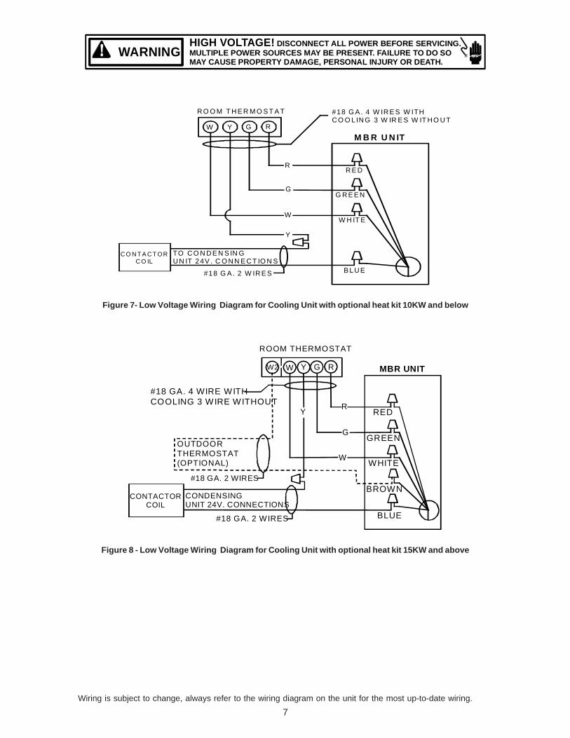
HIGH VOLTAGE! DISCONNECT ALL POWER BEFORE SERVICING.MULTIPLE POWER SOURCES MAY BE PRESENT. FAILURE TO DO SOMAY CAUSE PROPERTY DAMAGE, PERSONAL INJURY OR DEATH.
WARNING
R O O M T H E R M O S T A T
W Y G R
#18 G A . 4 W IR E S W ITHC O O LIN G 3 W IR E S W IT H O U T
R
G
W
Y
TO C O N D E N S IN GU N IT 24V . C O N N E C T IO N S
#18 G A . 2 W IR E S B LU E
W H IT E
G R E E N
R E D
C O N T A C T O RC O IL
M B R U N IT
Figure 7- Low Voltage Wiring Diagram for Cooling Unit with optional heat kit 10KW and below
W2 W Y G R
R
G
Y
W
GREEN
RED
WHITE
BLUE
BROWN
#18 GA. 4 WIRE WITHCOOLING 3 WIRE WITHOUT
ROOM THERMOSTAT
OUTDOOR THERMOSTAT(OPTIONAL)
CONDENSINGUNIT 24V. CONNECTIONS
#18 GA. 2 WIRES
#18 GA. 2 WIRES
CONTACTORCOIL
MBR UNIT
Figure 8 - Low Voltage Wiring Diagram for Cooling Unit with optional heat kit 15KW and above
Wiring is subject to change, always refer to the wiring diagram on the unit for the most up-to-date wiring.

8
HIGH VOLTAGE! DISCONNECT ALL POWER BEFORE SERVICING.MULTIPLE POWER SOURCES MAY BE PRESENT. FAILURE TO DO SOMAY CAUSE PROPERTY DAMAGE, PERSONAL INJURY OR DEATH.
WARNING
HEAT PUMP
C W2 O Y R#18 GA. 7 WIRE
RED
R
BRG
SEE NOTE 3
W
GREEN
WHITE
BLBLUE
R
Y
O
W
BL#18 GA. 5 WIRE
OUTDOOR THERMOSTAT(OPTIONAL) MAKE ON FALL
CONVENTIONALROOM THERMOSTAT
Y O C W2 G R E
HEAT PUMP
C W2 O Y R
RED
YELLOW
ORANGE
WHITE
BLUE
R
Y
O
W
BL
OT-1
OT-2
#18 GA. 5 WIRE
#18 GA. 7 WIRE NEEDED WHEN (2) OTs ARE USED
BL
EHR
SEE NOTE 3
W
1 2
3 4
BLUE
BROWN
WHITE
GREENSEE NOTE 2
G
CONVENTIONALROOM THERMOSTAT
Y O C W2 G R E
R
#18 GA. 7 WIRE
MBRSYSTEM COMPOSITE DIAGRAM
800-200010 KW & BELOW
MBRSYSTEM COMPOSITE DIAGRAM
1200-2000ABOVE 10 KW
NOTES1) OUTDOOR THERMOSTAT (OT-1) SHOULD BE THE FIRST TO CLOSE AND THE FIRST TO OPEN.2) IF OUTDOOR THERMOSTAT IS NOT USED. TIE WHITEAND BROWN WIRES FROM AIR HANDLER TOGETHER.3) REMOVE WIRE WHEN USING OUTDOOR T-STAT. #18 GA. 7 WIRE NEEDED WHEN (2) OTs ARE USED
NOMENCLATUREOT - OUTDOOR THERMOSTAT (OPTIONAL)MOF - MAKE ON FALLEHR - EMERGENCY HEAT RELAY (OPTIONAL)
COLOR CODESR - RED O - ORANGEY - YELLOW W - WHITEBL - BLUE PK - PINKV - VIOLET G - GREENBR - BROWN
SEE NOTE 1
#18 GA. 6 WIRE NEEDED WHEN OT IS USED
FIGURE 9
FIGURE 10
MBR UNIT
RED
MBR UNIT
Wiring is subject to change, always refer to the wiring diagram on the unit for the most up-to-date wiring.

9
HIGH VOLTAGE! DISCONNECT ALL POWER BEFORE SERVICING.MULTIPLE POWER SOURCES MAY BE PRESENT. FAILURE TO DO SOMAY CAUSE PROPERTY DAMAGE, PERSONAL INJURY OR DEATH.
WARNING
SINGLE STAGE COOLING WITH SINGLE OR TWO STAGE HEATING
COOLING ONLY - 2 STAGE HEAT THERMOSTAT
NOTES:1.) Y/Y2 ENABLES HI SPD FAN COOLING
2.) E/W1 ENABLES LO SPD FAN HEATING W/W2 ENABLES HI SPD FAN HEATING 3.) OT1 PJ4 MUST BE CUT FOR THIS CONFIGURATION
OTCO RCE\W1 W/W2 Y1OT1 OT2
YCONCONDENSER
PLEASE REFERTO MANUALFOR PROPERDIP SWITCHCONFIGURATION.
R
DIP
(CFM)
ON
OFF
OUTDOOR
W1
HUM
OT2
OT1W2
HEATPUMPCOM O W2 ED
SW
ITC
H
HEATERW1 W2
24 VACC R
CONDENSINGUNIT
THERMOSTATS
IF N
EED
ED
Y/Y2G HUM
Y1
HUMIDISTAT(OPTIONAL)
HUMIDISTAT
ROOMTHERMOSTAT
W2 C R G YW1
2nd STAGE HEATER1st STAGE HEATER
SEE NOTE 4
4.) CUT HUM PJ6 JUMPER IF USING HUMIDISTAT STAT OPENS ON HUMIDITY RISE
5.) DIP SWITCH #4 MUST BE IN THE "ON" POSITION
PN B1368274
Figure 11
COOLING ONLY - 2 STAGE HEAT (1st ROOM T'STAT & 2nd OT)
ROOMTHERMOSTAT
W C R G Y
OT2OT1 Y1W/W2E\W1 C RO OTC
CONFIGURATION.DIP SWITCHFOR PROPERTO MANUALPLEASE REFER
CONDENSERYCONR
DIP
(CFM)
ON
OFF
OUTDOOR
W1
HUM
OT2
OT1W2
HEATPUMPCOM O W2 ED
SW
ITC
H
HEATERW1 W2
24 VACC R
CONDENSINGUNIT
THERMOSTATS
IF N
EED
ED
HUMG Y/Y2
Y1
SEE NOTE 4
HUMIDISTAT(OPTIONAL)
HUMIDISTAT
NOTES:1.) Y/Y2 ENABLES HI SPD FAN COOLING
2.) E/W1 ENABLES LO SPD FAN HEATING E/W1 WITH OT CLOSED ENABLES HI SPD FAN HEATING 3.) OT1 PJ4 MUST BE CUT FOR THIS CONFIGURATION
5.) DIP SWITCH #4 MUST BE IN THE "ON" POSITION
2nd STAGE HEATER1st STAGE HEATER
OUTDOORTHERMOSTAT
1st STAGE ENABLED THRU ROOM T'STAT2nd STAGE ENABLED THRU CLOSED OT
4.) CUT HUM PJ6 JUMPER IF USING HUMIDISTAT STAT OPENS ON HUMIDITY RISE
PN B1368274
Figure 12
Wiring is subject to change, always refer to the wiring diagram on the unit for the most up-to-date wiring.

10
HIGH VOLTAGE! DISCONNECT ALL POWER BEFORE SERVICING.MULTIPLE POWER SOURCES MAY BE PRESENT. FAILURE TO DO SOMAY CAUSE PROPERTY DAMAGE, PERSONAL INJURY OR DEATH.
WARNING
COOLING ONLY - 2 STAGE HEAT (T'STAT ENABLED OT)
NOTES:1.) Y/Y2 ENABLES HI SPD FAN COOLING
2.) E/W1 ENABLES LO SPD FAN HEATING W/W2 WITH OT CLOSED ENABLES HI SPD FAN HEATING 3.) OT1 PJ4 MUST BE CUT FOR THIS CONFIGURATION OT2 PJ2 MUST BE CUT FOR THIS CONFIGURATION
4.) CUT HUM PJ6 JUMPER IF USING HUMIDISTAT STAT OPENS ON HUMIDITY RISE 5.) DIP SWITCH #4 MUST BE IN THE "ON" POSITION
OT2
PLEASE REFERTO MANUALFOR PROPERDIP SWITCHCONFIGURATION.
(CFM)
HUM
ON
DIP
OFF
YCONCONDENSER
R
E\W1
CONDENSINGUNIT
OUTDOOR
THERMOSTATS
HEATPUMP
W1OT1
COM O
W2
W2 ED
W/W2 O OTC OT1
W1 W2
SW
ITC
H
HEATERC R24 VAC
OT2 C R Y1
W1
IF N
EE
DE
D
THERMOSTATROOM
W2 C R G
2nd STAGE HEATER1st STAGE HEATER
HUMIDISTAT(OPTIONAL)
SEE NOTE 4
Y1
HUMHUMIDISTAT
Y/Y2G
Y
OUTDOORTHERMOSTAT
1st STAGE ENABLED THRU ROOM T'STAT2nd STAGE ENABLED THRU ROOM T'STAT AND CLOSED OT2
PN B1368274
Figure 13
HEAT PUMP WITH SINGLE OR TWO-STAGE HEATING (OPTIONS FOR EMERGENCY HEAT)
REMOVEPRODUCTIONWIRE Y1-O
Figure 14Wiring is subject to change, always refer to the wiring diagram on the unit for the most up-to-date wiring.

11
HIGH VOLTAGE! DISCONNECT ALL POWER BEFORE SERVICING.MULTIPLE POWER SOURCES MAY BE PRESENT. FAILURE TO DO SOMAY CAUSE PROPERTY DAMAGE, PERSONAL INJURY OR DEATH.
WARNING
REMOVEPRODUCTIONWIRE Y1-O
Figure 15O
FFON
SW
ITC
HIF
NE
EDED
REMOVEPRODUCTIONWIRE Y1-O
Figure 16
Wiring is subject to change, always refer to the wiring diagram on the unit for the most up-to-date wiring.

12
HIGH VOLTAGE! DISCONNECT ALL POWER BEFORE SERVICING.MULTIPLE POWER SOURCES MAY BE PRESENT. FAILURE TO DO SOMAY CAUSE PROPERTY DAMAGE, PERSONAL INJURY OR DEATH.
WARNING
REMOVEPRODUCTIONWIRE Y1-O
Figure 17
OT2
W1
OT1OW/W2 OTC
3.) OT1 PJ4 AND 0T2 PJ2 MUST BE CUT FOR THIS CONFIGURATION
CONFIGURATION.
R
OT1
OT2
W2W1
YCON O W2
OUTDOOR
O
R YCON O W2
O
GY1RC
W224 VAC
C R
Y1
G
(OPTIONAL)
REMOVEPRODUCTIONWIRE Y1-O
Figure 18
Wiring is subject to change, always refer to the wiring diagram on the unit for the most up-to-date wiring.
13
HIGH VOLTAGE! DISCONNECT ALL POWER BEFORE SERVICING.MULTIPLE POWER SOURCES MAY BE PRESENT. FAILURE TO DO SOMAY CAUSE PROPERTY DAMAGE, PERSONAL INJURY OR DEATH.
WARNING
TWO-STAGE COOLING WITH CONVENTIONAL TWO-STAGE THERMOSTAT
2 SPD COOLING ONLY - WITH 1 STAGE ELECTRIC HEAT
EE
E
Y1W/W2E W1 O OTC
CONFIGURATION.DIP SWITCHFOR PROPERTO MANUALPLEASE REFER
CONDENSERYCON
DIP
(CFM)
O O
OUTDOOR
W1
HUM
W2
HEATPUMPCOM O W2 ED
SWI
HEATERW1 W2
24 VAC
THERMOSTATSHUMG Y/Y2
Y1
HUMIDISTAT
C
NOTES:1.) Y1 ENABLES LO SPD FAN COOLING Y/Y2 ENABLES HI SPD FAN COOLING
2.) E/W1 ENABLES HI SPD FAN HEATING
3.) IF OT1 PJ4 JUMPER IS CUT E/W1 ENABLES LOW SPD FAN HEATING
4.) CUT HUM PJ6 JUMPER IF USING HUMIDISTAT STAT OPENS ON HUMIDITY RISE
5.)DIP SWITCH #4 MUST BE IN THE “OFF” POSITION
2-SPDCONDENSING
UNIT
ROOMTHERMOSTAT
CW
HUMIDISTAT(OPTIONAL)
SEE NOTE 4
1st STAGE HEATER
Figure 19
2 SPD COOLING ONLY - WITH 2 STAGE HEAT THERMOSTAT
\
Y2
C
Y1NOTES:1.) Y1 ENABLES LO SPD FAN COOLING Y/Y2 ENABLES HI SPD FAN COOLING
2.) E/W1 ENABLES HI SPD FAN HEATING
3.) IF OT1 PJ4 JUMPER IS CUT E/W1 ENABLES LOW SPD FAN HEATING
4.) CUT HUM PJ6 JUMPER IF USING HUMIDISTAT STAT OPENS ON HUMIDITY RISE
5.)DIP SWITCH #4 MUST BE IN THE “OFF” POSITION
2-SPDCONDENSING
UNIT
ROOMTHERMOSTAT
HUMIDISTAT(OPTIONAL)
SEE NOTE 4
1st STAGE HEATER
CW
Figure 20
Wiring is subject to change, always refer to the wiring diagram on the unit for the most up-to-date wiring.

14
HIGH VOLTAGE! DISCONNECT ALL POWER BEFORE SERVICING.MULTIPLE POWER SOURCES MAY BE PRESENT. FAILURE TO DO SOMAY CAUSE PROPERTY DAMAGE, PERSONAL INJURY OR DEATH.
WARNING
2 SPD COOLING ONLY - WITH 2 STAGE HEAT THERMOSTAT
\
Y2
C
Y1
2-SPDCONDENSING
UNIT
NOTES:1.) Y1 ENABLES LO SPD FAN COOLING Y/Y2 ENABLES HI SPD FAN COOLING
2.) E/W1 ENABLES HI SPD FAN HEATING
3.) IF OT1 PJ4 JUMPER IS CUT E/W1 ENABLES LOW SPD FAN HEATING
4.) CUT HUM PJ6 JUMPER IF USING HUMIDISTAT STAT OPENS ON HUMIDITY RISE
5.)DIP SWITCH #4 MUST BE IN THE “OFF” POSITION
CW
HUMIDISTAT(OPTIONAL)
SEE NOTE 4
1st STAGE HEATER
ROOMTHERMOSTAT
Figure 21
PLEASE REFERTO MANUALFOR PROPERDIP SWITCH(CFM)
HUM
ON
DIP
OFF
YCONR
OUTDOOR
THERMOSTATS
HEATPUMP
W1
COM
W2
W2 ED
W1 W2
SW
ITC
H
HEATERC R24 VAC
C R Y1
IF N
EED
ED
Y1
HUMHUMIDISTAT
GW1 W2 RC Y1 Y2
2 SPD COOLING ONLY - 2 STAGE HEAT (T'STAT ENABLED OT)
NOTES:1.) Y1 ENABLES LO SPD FAN COOLING Y/Y2 ENABLES HI SPD FAN COOLING
2.) E/W1 ENABLES LOW SPD FAN HEATING W/W2 WITH OT CLOSED ENABLES HI SPD FAN HEATING
3.) OT1 PJ4 MUST BE CUT FOR THIS CONFIGURATION OT2 PJ2 MUST BE CUT FOR THIS CONFIGURATION
4.) CUT HUM PJ6 JUMPER IF USING HUMIDISTAT STAT OPENS ON HUMIDITY RISE5.)DIP SWITCH #4 MUST BE IN THE “OFF” POSITION
1st STAGE HEATER2nd STAGE HEATER
2-SPDCONDENSING
UNIT
ROOMTHERMOSTAT
HUMIDISTAT(OPTIONAL)
OUTDOORTHERMOSTAT
SEE NOTE 4
Figure 22
Wiring is subject to change, always refer to the wiring diagram on the unit for the most up-to-date wiring.

15
HIGH VOLTAGE! DISCONNECT ALL POWER BEFORE SERVICING.MULTIPLE POWER SOURCES MAY BE PRESENT. FAILURE TO DO SOMAY CAUSE PROPERTY DAMAGE, PERSONAL INJURY OR DEATH.
WARNING
HEAT PUMP WITH SINGLE OR TWO STAGE HEATING WITH CONVENTIONAL THERMOSTAT(OPTIONS FOR EMERGENCY HEAT)
HEATPUMP - WITH 1 STG EMHT 1 STG AUX HEAT
NOTES:1.) Y ENABLES HI SPD FAN COOLING
2.) E AND W2 ENABLE HI SPD FAN HEATING 3.) IF OT2 PJ2 JUMPER IS CUT E AND W2 ENABLE LO SPD FAN HEATING
HUMIDISTAT(OPTIONAL)IF
NEE
DE
D
OT2OT1 Y1W/W2E\W1 C RO OTC
CONFIGURATION.DIP SWITCHFOR PROPERTO MANUALPLEASE REFER
YCONR
DIP
(CFM)
ON
OFF
OUTDOOR
W1
HUM
OT2
OT1W2
HEATPUMPCOM O W2 ED
SW
ITC
H
HEATERW1 W2
24 VACC R
THERMOSTATSHUMG Y/Y2
Y1
HUMIDISTAT
ROOMTHERMOSTAT
E C R G Y
HEATPUMP
R Y C O W2
HEATPUMPYCONR COM O W2 ED
W2 O
4.) CUT HUM PJ6 JUMPER IF USING HUMIDISTAT STAT OPENS ON HUMIDITY RISE
5.) DIP SWITCH #4 MUST BE IN THE "ON" POSITION
REMOVEPRODUCTIONWIRE Y1-O
Figure 23
J1
R1
PN B1368274
R3
CR10
R2
CR9
PJ6
PJ2
PJ4OT1
OT2
HUM
12
34
56
78
PLEASE REFERTO MANUALFOR PROPERDIP SWITCHCONFIGURATION.
W1 W2
R YCON COM O W2 ED
SWITCH
DIP
ON
OFF
24 VACC R
Y1
W2W1
OUTDOOR
HEATPUMPCONDENSER
DS1 CR1
CR2CR5CR6
CR7CR8
CR3
CR11
J2J3
1
4
C2
1
5
Y1RC G Y/Y2OT2 HUMHUMIDISTAT
OT1OTCW/W2E\W1THERMOSTATS
YCON COM O W2 EDHEATPUMPCONDENSER
C O W2 W2E CYR R YGIFNEEDE
HEATPUMP - 2 STG EMHT 1 STG AUX HEAT
O
O
ROOMTHERMOSTAT
HUMIDISTAT(OPTIONAL)
SEE NOTE 4
1st STAGE HEATER
2nd STAGE HEATER
NOTES:1.) Y ENABLES HI SPD FAN COOLING 2.) W2 ENABLES HI SPD FAN HEATING
E ENABLES LOW SPD FAN HEATING
3.) OT1 PJ4 MUST BE CUT FOR THIS CONFIGURATION
4.) CUT HUM PJ6 JUMPER IF USING HUMIDISTAT STAT OPENS ON HUMIDITY RISE
5.) DIP SWITCH #4 MUST BE IN THE “ON” POSITION
REMOVEPRODUCTIONWIRE Y1-O
Figure 24
Wiring is subject to change, always refer to the wiring diagram on the unit for the most up-to-date wiring.
16
HIGH VOLTAGE! DISCONNECT ALL POWER BEFORE SERVICING.MULTIPLE POWER SOURCES MAY BE PRESENT. FAILURE TO DO SOMAY CAUSE PROPERTY DAMAGE, PERSONAL INJURY OR DEATH.
WARNING
J1
PN. B1368274
PJ6
PJ2
PJ4OT1
OT2
HUM
12
34
56
78W1 W2
COM W2
DIP
24 VACW2W1
OUTDOOR
HEATPUMP
J2J3
1
4
1
5
Y/Y2OT2 HUMHUMIDISTAT
OT1OTCW/W2E\W1THERMOSTATS
GOODMAN MFG. CO. L.P.
COM W2HEATPUMP
W2 W2
IF N
EEDE
D
HUMIDISTAT(OPTIONAL)
REMOVEPRODUCTIONWIRE Y1-O
SEE NOTE 4
2nd STAGE HEATER
OUTDOORTHERMOSTAT
NOTES:1.) Y ENABLES HI SPD FAN COOLING2.) E ENABLES LO SPD FAN HEATING W2 ENABLES LOW SPD FAN HEATING W2 AND OT2 CLOSED ENABLES HI SPD FAN HEATING
3.) OT1 PJ2 MUST BE CUT FOR THIS CONFIGURATION
4.) CUT HUM PJ6 JUMPER IF USING HUMIDISTAT STAT OPENS ON HUMIDITY RISE
5.) DIP SWITCH #4 MUST BE IN THE "ON" POSITION
HEATPUMP - 2 STG EMHT 2 STAG AUX - 1 OUTDOOR T-STAT
1ST STAGE HEATER
O
ROOMTHERMOSTATHEATPUMP
Figure 25
J1
PN. B13682704
HUM
R YCON COM ED
TCH
N
C R
CONDENSER
DS1
J2J3
1
4
1
5
RC HUM
R YCON COM EDCONDENSER
IF
O
HUMIDISTAT(OPTIONAL)
SEE NOTE 4
ROOMTHERMOSTATHEATPUMP
NOTES:1.) Y ENABLES HI SPD FAN COOLING 2.) W2 AND OT1 CLOSED ENABLES LOW SPD FAN HEATING W2 AND OT2 CLOSED ENABLES HI SPD FAN HEATING.
E ENABLES LOW SPD FAN HEATING
3.) IF OT2 PJ4 AND OT2 PJ2 MUST BE CUT FOR THIS CONFIGURATION
4.) CUT HUM PJ6 JUMPER IF USING HUMIDISTAT STAT OPENS ON HUMIDITY RISE
5.) DIP SWITCH #4 MUST BE IN THE “ON” POSITION
NO AUX HEAT IN HEATPUMP MODE UNTIL OUTDOOR T’STAT CLOSES
REMOVEPRODUCTIONWIRE Y1-O
Figure 26
Wiring is subject to change, always refer to the wiring diagram on the unit for the most up-to-date wiring.

17
HIGH VOLTAGE! DISCONNECT ALL POWER BEFORE SERVICING.MULTIPLE POWER SOURCES MAY BE PRESENT. FAILURE TO DO SOMAY CAUSE PROPERTY DAMAGE, PERSONAL INJURY OR DEATH.
WARNING
J1
PN. B1368274
PJ6
PJ2
PJ4OT1
OT2
HUM
12
34
56
78W1 W2
COM W2
DIP
24 VACW2W1
OUTDOOR
HEATPUMP
J2J3
1
4
1
5
Y/Y2OT2 HUMHUMIDISTAT
OT1OTCW/W2E\W1THERMOSTATS
GOODMAN MFG. CO. L.P.
COM W2HEATPUMP
W2 W2
IF N
EE
DE
D
HUMIDISTAT(OPTIONAL)
SEE NOTE 4
2nd STAGE HEATER
OUTDOORTHERMOSTAT
NOTES:1.) Y ENABLES HI SPD FAN COOLING2.) E ENABLES LO SPD FAN HEATING W2 AND OT2 CLOSED ENABLES HI SPD FAN HEATING
3.) OT1 PJ4 AND OT2 PJ2 MUST BE CUT FOR THIS CONFIGURATION
4.) CUT HUM PJ6 JUMPER IF USING HUMIDISTAT STAT OPENS ON HUMIDITY RISE
5.) DIP SWITCH #4 MUST BE IN THE "ON" POSITION
HEATPUMP - 2 STG EMHT 1 STG AUX - 1 OUTDOOR T'STAT
1ST STAGE HEATER
O
ROOMTHERMOSTAT
REMOVEPRODUCTIONWIRE Y1-O
Figure 27
2 SPEED HEAT PUMP WITH SINGLE OR TWO-STAGE HEATING(OPTIONS FOR EMERGENCY HEAT) WITH CONVENTIONAL TWO-STAGE THERMOSTAT
J1
PN. B1368274
PJ6
PJ2
PJ4OT1
OT2
HUM
12
34
56
78W1 W2
COM W2
DIP
24 VACW2W1
OUTDOOR
HEATPUMP
J2J3
1
4
1
5
Y/Y2OT2 HUMHUMIDISTAT
OT1OTCW/W2E\W1THERMOSTATS
GOODMAN MFG. CO. L.P.
COM W2HEATPUMP
W2 W2
IF N
EE
DE
D
HEATPUMP - WITH 1 STG EMHT 1 STG AUX HEAT
O
ROOMTHERMOSTAT
HUMIDISTAT(OPTIONAL)
SEE NOTE 4
1st STAGE HEATER2nd STAGE HEATER
NOTES:1.) Y ENABLES HI SPD FAN COOLING 2.)
E ENABLES LOW SPD FAN HEATING
3.) IF OT2 PJ2 JUMBER IS CUT “E’ AND “W2” ENABLE LOW SPD FAN HEATING
4.) CUT HUM PJ6 JUMPER IF USING HUMIDISTAT STAT OPENS ON HUMIDITY RISE
5.) DIP SWITCH #4 MUST BE IN THE “OFF” POSITION
REMOVEPRODUCTIONWIRE Y1-O
Figure 28Wiring is subject to change, always refer to the wiring diagram on the unit for the most up-to-date wiring.

18
HIGH VOLTAGE! DISCONNECT ALL POWER BEFORE SERVICING.MULTIPLE POWER SOURCES MAY BE PRESENT. FAILURE TO DO SOMAY CAUSE PROPERTY DAMAGE, PERSONAL INJURY OR DEATH.
WARNING
R YCON COM O W2 EDHEATPUMPCONDENSER
C O W2 W2E CY2R R Y2G
IF N
EE
DE
DHEATPUMP - WITH 1 STG EMHT 1 STG AUX HEAT
Y1 Y1
J1
R1
R3
CR10
R2
CR9
PJ6
PJ2
PJ4OT1
OT2
HUM
12
34
56
78
PLEASE REFERTO MANUALFOR PROPERDIP SWITCHCONFIGURATION.
W1 W2
R YCON COM O W2 ED
SWITCH
DIP
ON
OFF
24 VACC R
Y1
W2W1
OUTDOOR
HEATPUMPCONDENSER
DS
1 CR1
CR2CR5
CR6
CR7CR8
CR3
CR11
J2J3
1
4
C2
1
5
Y1RC G Y/Y2OT2 HUMHUMIDISTAT
OT1OTCW/W2E\W1THERMOSTATS
O
HUMIDISTAT(OPTIONAL)
SEE NOTE 4
O
1st STAGE HEATER2nd STAGE HEATER
ROOMTHERMOSTAT2 SPD HEATPUMP
NOTES:1.) Y ENABLES HI SPD FAN COOLING 2.) E AND W2 ENABLE HI SPD FAN COOLING
3.) IF OT2 PJ2 JUMPER IS CUT “E” AND “W2” ENABLE LOW SPD FAN HEATING
4.) CUT HUM PJ6 JUMPER IF USING HUMIDISTAT STAT OPENS ON HUMIDITY RISE
5.) DIP SWITCH #4 MUST BE IN THE “OFF” POSITION
REMOVEPRODUCTIONWIRE Y1-O
Figure 29
R YCON COM O W2 EDHEATPUMPCONDENSER
C O W2 W2E CY2R R Y2G
IF N
EE
DE
D
HEATPUMP - 2 STG EMHT 1 STG AUX HEAT
Y1 Y1
J1
R1
R3
CR10
R2
CR9
PJ6
PJ2
PJ4OT1
OT2
HUM
12
34
56
78
PLEASE REFERTO MANUALFOR PROPERDIP SWITCHCONFIGURATION.
W1 W2
R YCON COM O W2 ED
SWITCH
DIP
ON
OFF
24 VACC R
Y1
W2W1
OUTDOOR
HEATPUMPCONDENSER
DS
1 CR1
CR2CR5
CR6
CR7CR8
CR3
CR11
J2J3
1
4
C2
1
5
Y1RC G Y/Y2OT2 HUMHUMIDISTAT
OT1OTCW/W2E\W1THERMOSTATS
O
HUMIDISTAT(OPTIONAL)
SEE NOTE 4
ROOMTHERMOSTAT2 SPD HEATPUMP
1st STAGE HEATER2nd STAGE HEATER
O
NOTES:1.) Y ENABLES HI SPD FAN COOLING 2.) W2 ENABLES HI SPD FAN HEATING
E ENABLES LOW SPD FAN HEATING
3.) IF OT2 PJ4 MUST BE CUT FOR THIS CONFIGURATION
4.) CUT HUM PJ6 JUMPER IF USING HUMIDISTAT STAT OPENS ON HUMIDITY RISE
5.) DIP SWITCH #4 MUST BE IN THE “OFF” POSITION
REMOVEPRODUCTIONWIRE Y1-O
Figure 30
Wiring is subject to change, always refer to the wiring diagram on the unit for the most up-to-date wiring.

19
HIGH VOLTAGE! DISCONNECT ALL POWER BEFORE SERVICING.MULTIPLE POWER SOURCES MAY BE PRESENT. FAILURE TO DO SOMAY CAUSE PROPERTY DAMAGE, PERSONAL INJURY OR DEATH.
WARNING
R YCON COM O W2 EDHEATPUMPCONDENSER
C O W2 W2E CY2R R Y2G
IF N
EE
DE
DHEATPUMP - 2 STG EMHT 2 STG AUX - 1 OUTDOOR T'STAT
Y1 Y1O
J1
R1
R3
CR10
R2
CR9
PJ6
PJ2
PJ4OT1
OT2
HUM
12
34
56
78
PLEASE REFERTO MANUALFOR PROPERDIP SWITCHCONFIGURATION.
W1 W2
R YCON COM O W2 ED
SWITCH
DIP
ON
OFF
24 VACC R
Y1
W2W1
OUTDOOR
HEATPUMPCONDENSER
DS
1 CR1
CR2CR5
CR6
CR7CR8
CR3
CR11
J2J3
1
4
C2
1
5
Y1RC G Y/Y2OT2 HUMHUMIDISTAT
OT1OTCW/W2E\W1THERMOSTATS
HUMIDISTAT(OPTIONAL)
SEE NOTE 4
ROOMTHERMOSTAT2-SPD HEATPUMP
1st STAGE HEATER2nd STAGE HEATER
NOTES:1.) Y ENABLES HI SPD FAN COOLING 2.) W2 ENABLES LOW SPD FAN HEATING W2 AND OT2 CLOSED ENABLES HI SPD FAN HEATING.
E ENABLES LOW SPD FAN HEATING
3.) IF OT2 PJ4 MUST BE CUT FOR THIS CONFIGURATION
4.) CUT HUM PJ6 JUMPER IF USING HUMIDISTAT STAT OPENS ON HUMIDITY RISE
5.) DIP SWITCH #4 MUST BE IN THE “OFF” POSITION
O
1ST STAGE AUX HEAT ENABLED BY ROOM T’STAT2ND STAGE AUX ENABLED BY ROOM T’STAT AND OUTDOOR T’STAT
REMOVEPRODUCTIONWIRE Y1-O
Figure 31
R YCON COM O W2 EDHEATPUMPCONDENSER
C O W2 W2E CY2R R Y2G
IF N
EE
DE
D
HEATPUMP - 2 STG EMHT 2 STG AUX - 2 OUTDOOR T'STATS
Y1 Y1O
J1
R1
R3
CR10
R2
CR9
PJ6
PJ2
PJ4OT1
OT2
HUM
12
34
56
78
PLEASE REFERTO MANUALFOR PROPERDIP SWITCHCONFIGURATION.
W1 W2
R YCON COM O W2 ED
SWITCH
DIP
ON
OFF
24 VACC R
Y1
W2W1
OUTDOOR
HEATPUMPCONDENSER
DS
1 CR1
CR2
CR5CR6
CR7
CR8CR3
CR11
J2J3
1
4
C2
1
5
Y1RC G Y/Y2OT2 HUMHUMIDISTAT
OT1OTCW/W2E\W1THERMOSTATS
OT1 OT2OTC
OUTDOOR
HUMIDISTAT(OPTIONAL)
SEE NOTE 4
ROOMTHERMOSTAT2 SPD HEATPUMP
1st STAGE HEATER2nd STAGE HEATER
OT1
O
NOTES:1.) Y ENABLES HI SPD FAN COOLING 2.) W2AND OT1 CLOSED ENABLES LOW SPD FAN HEATING W2 AND OT2 CLOSED ENABLES HI SPD FAN HEATING.
E ENABLES LOW SPD FAN HEATING
3.) OT1 PJ4 AND OT2 PJ2 MUST BE CUT FOR THIS CONFIGURATION
4.) CUT HUM PJ6 JUMPER IF USING HUMIDISTAT STAT OPENS ON HUMIDITY RISE
5.) DIP SWITCH #4 MUST BE IN THE “OFF” POSITION
NO AUX HEAT IN HEATPUMP MODE UNTIL OUTDOOR T’STAT CLOSES
OT2
REMOVEPRODUCTIONWIRE Y1-O
Figure 32
Wiring is subject to change, always refer to the wiring diagram on the unit for the most up-to-date wiring.

20
HIGH VOLTAGE! DISCONNECT ALL POWER BEFORE SERVICING.MULTIPLE POWER SOURCES MAY BE PRESENT. FAILURE TO DO SOMAY CAUSE PROPERTY DAMAGE, PERSONAL INJURY OR DEATH.
WARNING
R YCON COM O W2 EDHEATPUMPCONDENSER
C O W2 W2E CY2R R Y2G
IF N
EE
DE
DHEATPUMP - 2 STG EMHT 1 STG AUX - 1 OUTDOOR T'STAT
Y1 Y1O
J1
R1
R3
CR10
R2
CR9
PJ6
PJ2
PJ4OT1
OT2
HUM
12
34
56
78
PLEASE REFERTO MANUALFOR PROPERDIP SWITCHCONFIGURATION.
W1 W2
R YCON COM O W2 ED
SWITCH
DIP
ON
OFF
24 VACC R
Y1
W2W1
OUTDOOR
HEATPUMPCONDENSER
DS
1 CR1
CR2CR5
CR6
CR7CR8
CR3
CR11
J2J3
1
4
C2
1
5
Y1RC G Y/Y2OT2 HUMHUMIDISTAT
OT1OTCW/W2E\W1THERMOSTATS
HUMIDISTAT(OPTIONAL)
SEE NOTE 4
ROOMTHERMOSTAT2-SPD HEATPUMP
1st STAGE HEATER2nd STAGE HEATER
NO AUX HEAT IN HEATPUMP MODE UNTIL T’STAT CLOSES
O
NOTES:1.) Y ENABLES HI SPD FAN COOLING 2.) W2 AND OT2 CLOSED ENABLES HI SPD FAN HEATING
E ENABLES LOW SPD FAN HEATING
3.) OT1 PJ4 AND OT2 PJ2 MUST BE CUT FOR THIS CONFIGURATION
4.) CUT HUM PJ6 JUMPER IF USING HUMIDISTAT STAT OPENS ON HUMIDITY RISE
5.) DIP SWITCH #4 MUST BE IN THE “OFF” POSITION
OUTDOORTHERMOSTAT
REMOVEPRODUCTIONWIRE Y1-O
Figure 33
TWO STAGE COOLING WITH CONVENTIONAL TWO STAGE THERMOSTAT(ENCLOSED WITH ADD ON 1N006 DIODES)
TSTWK01 KIT REQUIRED
ENCODED THERM OSTAT
PN. B1368271 REV. A
ZD2ZD3 ZD1
TEST
1N4005DIODES
PN. B1368274
PJ6
PJ2
PJ4
HUM
PLEASE REFERTO MANUALFOR PROPERDIP SWITCHCONFIGURATION.
24 VAC
Y1HEATPUMP
Y1 Y/Y2 HUMHUMIDISTATTHERMOSTATS
24 V
230 V
2 SPD REMOTECONDENSING
UNIT
TSTWK01BOARD
TO COMMON ONTSTWK01 BOARD
TO Y ONTSTWK01 BOARD
HUMIDISTAT(OPTIONAL)HUMIDISTAT(OPTIONAL)
SEE NOTE 1
NOTES:1.) STAT OPENS ON HUMIDITY RISE2.) DIP SWITCH #4 MUST BE IN THE ON POSITION
CUT HUM PJ6 FOR HUMIDISTAT OPERATION
2ND STAGE HEATER
1ST STAGE HEATERCUT OT1 PJ4 FOR 2-STAGE HEAT OPERATION
TSTWK01TRANSFORMER
ENCODED 2 SPD COOLING - WITH 1 OR 2-STG HEAT
Figure 34
Wiring is subject to change, always refer to the wiring diagram on the unit for the most up-to-date wiring.

21
HIGH VOLTAGE! DISCONNECT ALL POWER BEFORE SERVICING.MULTIPLE POWER SOURCES MAY BE PRESENT. FAILURE TO DO SOMAY CAUSE PROPERTY DAMAGE, PERSONAL INJURY OR DEATH.
WARNING
ENCODED THERMOSTAT
PN. B1368271 REV. A
W1 W2
PJ6
PJ2
PJ4OT1
OT2
HUM
W1 W2
W2
DIP
24 VACW2W1
OUTDOOR
Y/Y2OT2 HUMHUMIDISTAT
OT1OTCE\W1THERMOSTATS
ENCODED 2 SPD COOLING - WITH 1 OR 2 STG HEAT - 1 OT
24 V
230 V
TSTWK01TRANSFORMER
TSTWK01BOARD
TO COMMON ONTSTWK01 BOARD
TO Y ONTSTWK01 BOARD
HUMIDISTAT(OPTIONAL)
SEE NOTE 2
2ND STAGE HEATER
1ST STAGE HEATER
OUTDOORTHERMOSTAT
NOTES:1.) OT2 CLOSED AND W2 DEMAND ENABLES2.) STAT OPENS ON HUMIDITY RISE3.) DIP SWITCH #4 MUST BE IN THE ON POSITION
CUT OT2 PJ2 FOR THIS CONFIGURATION
CUT HUM PJ6 FOR HUMIDISTAT OPERATION
2 SPD REMOTECONDENSING
UNIT
Figure 35
ENCODED TWO STAGE COOLING WITH GMC THERMOSTAT PART #CHET18-60TSTWKO1 KIT REQUIRED
GOODMAN MFG. CO. L.P.
PJ6
PJ2
PJ4OT1
OT2
HUM
12
34
56
78
PLEASE REFERTO MANUALFOR PROPERDIP SWITCHCONFIGURATION.
W1 W2
R YCON COM O W2 ED
SWITCH
DIP
ON
OFF
24 VACC R
Y1
W2W1
OUTDOOR
HEATPUMPCON DENSER
Y1RC G Y/Y2OT2 HUMHUMIDISTAT
OT1OTCW/W2E\W1THERMOSTATS
GOODMAN MFG. CO. L.P.
ENCODED 2 SPD COOLING - WITH 1 OR 2 STG HEAT
Y2Y1
C/X
YLO/Y1
Y/Y224 V
CHET 18-60ENCODED
THERMOSTAT2 SPD REMOTECONDENSING
UNIT
TSTWK01TRANSFORMER
TSTWK01BOARD
TO COMMON ONTSTWK01 BOARD
TO Y ONTSTWK01 BOARD
HUMIDISTAT(OPTIONAL)
SEE NOTE 1
2ND STAGE HEATER
1ST STAGE HEATERNOTES:1.) STAT OPENS ON HUMIDITY RISE2.) DIP SWITCH #4 MUST BE IN THE ON POSITION
CUT OT2 PJ2 FOR 2-STAGE HEAT OPERATION
CUT HUM PJ6 FOR HUMIDISTAT OPERATION
Figure 36
Wiring is subject to change, always refer to the wiring diagram on the unit for the most up-to-date wiring.
22
HIGH VOLTAGE! DISCONNECT ALL POWER BEFORE SERVICING.MULTIPLE POWER SOURCES MAY BE PRESENT. FAILURE TO DO SOMAY CAUSE PROPERTY DAMAGE, PERSONAL INJURY OR DEATH.
WARNING
ENCODED THERMOSTAT
PN. B1368271 REV. A
Q2K3
ZD2ZD3
Q1
ZD1
K2
K1
P1
GOODMAN MFG. CO. L.P.
J1
PJ6
PJ2
PJ4OT1
OT2
HUM
12
34
56
78
PLEASE REFERTO MANUALFOR PROPERDIP SWITCHCONFIGURATION.
W1 W2
R YCON COM O W2 ED
SWITCH
DIP
ON
OFF
24 VACC R
Y1
W2W1
OUTDOOR
HEATPUMP
J2J3
Y1RC G Y/Y2OT2 HUMHUMIDISTAT
OT1OTCW/W2E\W1THERMOSTATS
GOODMAN MFG. CO. L.P.
ENCODED 2 SPD COOLING - WITH 1 OR 2 STG HEAT - 1 OT
Y2Y1
C/X
YLO/Y1
Y/Y2
OUTDOORTHERMOSTAT
CHET 18-60ENCODED
THERMOSTAT2 SPD REMOTECONDENSING
UNIT
TSTWK01TRANSFORMER
TSTWK01BOARD
TO COMMON ONTSTWK01 BOARD
TO Y ONTSTWK01 BOARD
HUMIDISTAT(OPTIONAL)
SEE NOTE 2
2ND STAGE HEATER
1ST STAGE HEATERNOTES:1.) OT2 CLOSED AND W2 DEMAND ENABLES 2ND STG HEAT AND HI FAN2.) STAT OPENS ON HUMIDITY RISE3.) DIP SWITCH #4 MUST BE IN THE ON POSITION
CUT OT2 PJ2 FOR THIS CONFIGURATION
CUT HUM PJ6 FOR HUMIDISTAT OPERATION
Figure 37
Troubleshooting Encoded Two Stage Cooling Thermostats Options
TEST FUNCTION SIGNAL OUT SIGNAL FAN
ST
ET
S1 +
* S1 - *
S1 + -
S2 +
S2 -
S2 + -
S3 +
* S3 - *
* S3 + - *
R + -
COM
LOW SPEED COOL
* LO SPEED COOL *
HI SPEED COOL
LO SPEED HEAT
O
LO SPEED HEAT
HI SPEED HEAT
G
N/A
N/A
24 VAC
GND
YCON +
* YCON - *
YCON + -
W1 HEATER
ED -
( FUTURE USE )
W1 HEATER
W2 HEATER
NONE
N/A
N/A
R TO T'STAT
COM TO T'STAT
Y1
* Y / Y2 HI *
Y / Y2
W / W1
O
W / W1
EM / W2
G
N/A
N/A
R
C1 , C2
* ERROR CONDITION ( DIODE ON THERMOSTAT BACKWARDS )
* ERROR CONDITION ( S3 CAN ONLY READ + )
INDICATION
* ERROR CONDITION ( S3 CAN ONLY READ + )
INPUTFROM
THERMOSTAT
POWERTO
THERMOSTAT
NOTES:1.) THE TEST SPADE CAN BE CONNECTED TO ANY OTHER TEST SPADE ON EITHER BOARD.
2.) THE + LED WILL BE RED AND WILL LIGHT TO INDICATE + HALF CYCLES. THE - LED WILL BE GREEN AND WILL LIGHT TO INDICATE - HALF CYCLES. BOTH RED AND GREEN ILLUMINATED WILL INDICATE FULL CYCLES DENOTED BY + - .
3.) SIGNAL OUT CONDITION FOR W1 , W2 HEATER WILL BE AFFECTED BY OT1 PJ4 AND OT2 PJ2 JUMPERS AND OUTDOOR THERMOSTATS ATTACHED. THE TABLE ABOVE ASSUMES OT1 PJ4 IS REMOVED AND OT2 PJ2 IS MADE WITH NO OUTDOOR THERMOSTATS ATTACHED.
SEE NOTE 3
SEE NOTE 3
The chart above provides troubleshooting for either version of the encoded thermostat option. This provides diagnostic informa-tion for the GMC CHET18-60 or a conventional two cool / two stage heat thermostat with IN4005 diodes added as called out inthe above section.
Wiring is subject to change, always refer to the wiring diagram on the unit for the most up-to-date wiring.

23
A test lead or jumper wire can be added from the test terminalto any terminal on the B13682-74 or B13682-71 variable speedterminal board and provide information through the use of theLED lights on the B13682-71 VSTB control. Using this chart,a technician can determine if the proper input signal is beingreceived by the encoded VSTB control and diagnose any prob-lems that may be relayed to the output response of the B13682-74 VSTM control.Example:The system is calling for 1st stage cooling operation. The properinput signal from either thermostat option will cause the red “+”LED light to illuminate when the test terminal and the “S1”terminal are connected using a test lead or jumper wire. Thisverifies proper input from the thermostat. The proper output isa “YCON” signal to the RSG condensing unit. When a test
lead or jumper is connected between Test and YCON, the red“+” LED will illuminate. The corresponding response from theCKTS control will be an illuminated “LOW” LED light and 24Vapplied to the Low capacity contactor through the “LOW” ter-minal output.This similar procedure can be utilized on any terminal on theVSTB controls. The chart above indicates the proper input andLED status as well as the corresponding out signal. Eachmode of operation must be verified during the check out proce-dure when the units are installed. The LED light provides aeasy method to verify operation without the use of a multi-meter.

24Wiring is subject to change, always refer to the wiring diagram on the unit for the most up-to-date wiring.
HIGH VOLTAGE! DISCONNECT ALL POWER BEFORE SERVICING.MULTIPLE POWER SOURCES MAY BE PRESENT. FAILURE TO DO SOMAY CAUSE PROPERTY DAMAGE, PERSONAL INJURY OR DEATH.
WARNING
BK
BL
BK
L1 L2
BK
BK
HTR1TLHTR2
RD
9
8
7
R
WH
BLPU
TL
BK
5
6
3
4
BK
RD
1
2
WH
BK
L2L1
BK
RD
RD
RD
BK
R
HTR1 TL
L1
BK
6
8
9
7
2
RDPU
4
5
3
BK
RD
1
BK
L2 L1 L2
RD
YL
M1
M2
BK
RD
YL
RD
R1M4
RDBK
M3
HTR3 TL
HTR2
HTR1 TL
TL
PU
M2
R2
YL
M1
BL
WH
BR
BLRD
BK
RD
BK
TLHTR1
BK
HTR4
HTR3
HTR2
BK RD
9
7
8
L2L1 L1 L2
2
5
6
3
4
1
RD
M1YL
BK
M2
BL
WH 6
BL
RDBK
YL8
9
7
M6
M5M3
R1
M4
RDPU
M7
R2
M8
BL
TL
TL
TL
YL
BL
RD
BK
RDBL
BR
4
5
3
2
BK 1
ONE (1) ELEMENT ROWS TWO (2) ELEMENT ROWS THREE (3) ELEMENT ROWS FOUR (4) ELEMENT ROWS
FL
M1
M2
FL
FL
M1
M2
M3
M4
FL
FL
FL
FL
FL
FL
FL
USE COPPER WIRE
SPEEDUP
COPPER POWER SUPPLY(SEE RATING PLATE)
EQUIPMENT GROUND
BL BL
SEE NOTE 3
BK
M1
BR
BRRC
EM
RD
BL
BK
RDPU
WH
EBTDR
SR
BL
G
RDXFMR-RXFMR-C
C
R
RDGR
SEE NOTE 2
BL RD GR WH BR
5
NO
COM
NC
K1
K1
PU
PU
RD
RDC
BK
BR
PLF
BK
1
RD PU
2 3
240
24V 4
1 2 3
TR
RD
SEE NOTE 4
BL BR
4 5
WH
6 7 8 9
PLM
GRD
1
BK
2 3
RD
L2L1
4 5 6 7 8 9
0140M00170-D
PLMPLFTR
FACTORY WIRING
FIELD WIRING
NOTES:DELAY RELAY
STRAIN RELIEF
EVAPORATOR MOTOR
ELECTRONIC BLOWER TIME
RUN CAPACITORSR
EM
EBTDR
RC
BKRD
BLYL
BLUE
BLACKREDYELLOW
COMPONENT CODE
BROWNPURPLEGREEN
PUBR
GR
FEMALE PLUG CONNECTORMALE PLUG CONNECTOR
TRANSFORMER
HIGH VOLTAGE LOW VOLTAGE
HIGH VOLTAGE LOW VOLTAGE
PLF3 2
COLOR CODE
RD
TR
WH
6
BR
5 PLF4
4 24V 5
SEE NOTE 11 2 3
RC
HI
EM
GR
WIRING CODE
BL
EBTDR
LO COM
NCM1
EBTDR
NO
208/240 VOLTS
1
1
PLF
PLM
L1
PLM 2
L2
(M2)
PU
RC
(M1) BK
BL MEDIUM
3 SPEEDBR
HIGH
EM
(COM) RD LOW
IF REPLACEMENT OF THE ORIGINAL WIRES SUPPLIED WITH THIS ASSEMBLY IS NECESSARYUSE WIRE THAT CONFORMS TO THE NATIONAL ELECTRIC CODE.
M2
PU
(TR 1)
M2
R GCEBTDR
SEE NOTE 1
FL FUSE LINKTL THERMAL LIMIT
HTR HEAT ELEMENTS
SEE NOTE 5
R RELAY
TERMINAL BLOCK SHOWNFOR 50HZ MODELS ONLY
THREE SPEED MOTOR WIRING(SELECT MODELS ONLY)
SEE NOTE 3
MARK ACCORDING TO NUMBER OF HEATER ELEMENT ROWS INSTALLED. NO MARK INDICATES NO HEAT KIT INSTALLED.KIT COMBINATION ON THIS UNIT'S S&R PLATE. AFTER INSTALLING OPTIONAL HEAT KIT, MARK A "X" IN THE PROVIDED ABOVE.
NOTE: WHEN INSTALLING HEATER KIT, ENSURE SPEED TAP DOES NOT EXCEED MINIMUM BLOWER SPEED (MBS) SPECIFIED FOR THE AIRHANDLER/HEATER
WHITEWH
USE MIN. 75°C FIELD WIRE
1)) RED WIRES TO BE ON TRANSFERMER TERMINAL "3" FOR 240 VOLTS AND ON TERMINAL "2" FOR 208 VOLTS2) SEE COMPOSITE WIRING DIAGRAMS IN INSTALLATION INSTRUCTIONS FOR PROPER LOW VOLTAGE WIRING CONNECTIONS3) CONFIRM SPEED TAP SELECTED IS APPROPRIATE FOR APPLICATION. IF SPEED TAP NEEDS TO BE CHANGED, CONNECT APPROPRIATE MOTOR WIRE (RED FOR LOW, BLUE FOR MEDIUM,AND BLACK FOR HIGH SPEED) ON "COM" CONNECTION OF THE EBTDR INACTIVE MOTOR WIRES SHOULD BE CONNECTED TO "M1 OR M2" ON EBTDR.4) BROWN AND WHITE WIRES ARE USED WITH HEAT KITS ONLY.5) EBTDR HAS A 7 SECOND ON DELAY WHEN "G" IS ENERGIZED AND A 65 SECOND OFF DELAY WHEN "G" IS DE-ENERGIZED.