mc-ii plus exp user manual · mc-ii plus exp flow analyzer august 2005 1 introduction the nuflo...
TRANSCRIPT
Manual No. 101001394, Rev. F
NuFloTM
MC-II Plus EXP Flow Analyzer User Manual

© 2005 NuFlo Technologies, Inc. All information contained in this publication is confidential and proprietary property of NuFlo Technologies, Inc. Any reproduction or use of these instructions, drawings, or photographs without the express written permission of an officer of NuFlo Technologies, Inc. is forbidden.
All Rights Reserved.
Printed in the United States of America.
Manual No. 101001394, Rev. F August 2005
MC-II Plus EXP Flow Analyzer
August 2005 T-1
TABLE OF CONTENTS
Introduction ...........................................................................................................1 Specifications........................................................................................................2 Installation.............................................................................................................3 Operation ..............................................................................................................3 Error Detection......................................................................................................4 Calibration.............................................................................................................5
Liquid Measurement Using Preprogrammed Units of Measure..................6 Gas Measurement Using Preprogrammed Units of Measure.....................9 Liquid Measurement Using a Calculated Divisor and Rate Multiplier .......13 Gas Measurement Using a Calculated Divisor and Rate Multiplier ..........17
Time Out Feature................................................................................................20
Presetting Volume...............................................................................................21 Setting Flow Rate Filtering..................................................................................22 Setting Input Sensitivity.......................................................................................23 Configuring Pulse Output....................................................................................24 Configuring the 4-20 mA Rate Output.................................................................25 Setting a Security Code ......................................................................................27 Accessing an MC-II Plus with a Security Code ...................................................28 Appendix A - Installation ................................................................................... A-1
General .................................................................................................. A-1
Conversion to Alternate Mounting .......................................................... A-1 Mounting on the Flow Meter................................................................... A-2
MC-II Plus EXP Flow Analyzer
T-2 August 2005
Input / Output Features...........................................................................A-2
Pulse Output ...............................................................................A-2 External Power Supply.................................................................A-3 4-20 mA Rate Output ...................................................................A-3 Frequency Output ........................................................................A-3 Remote Reset Input .....................................................................A-4
MC-II Plus EXP Nomenclature ...............................................................A-5 Typical Mounting Dimensions.................................................................A-6 Alternate Mounting Dimensions..............................................................A-7 Installation to Flow Meter........................................................................A-8 Wiring Diagrams .....................................................................................A-9
Flow Meter Input ..........................................................................A-9 Pulse Output ..............................................................................A-10 External Power Supply...............................................................A-11 4-20 mA Rate Output .................................................................A-12 Frequency Output ......................................................................A-13 Reset Input with Power Supply and Reset Switch in Safe Area ...............................................................................A-14 Local Reset Input Using Explosion Proof Switch .......................A-15
Appendix B - Maintenance ................................................................................B-1
Battery Replacement ..............................................................................B-1 Circuit Assembly Replacement...............................................................B-2 Keypad Replacement .............................................................................B-2
MC-II Plus EXP Flow Analyzer
August 2005 T-3
Spare Parts List...................................................................................... B-3
Appendix C - Configuration Menu Flowchart .................................................... C-1 Appendix D - User Interface Prompt Glossary .................................................. D-1 Appendix E - Data Tables ................................................................................. E-1
Table 1 - Determining Atmospheric Pressure from Elevation................. E-1 Table 2 - Table of Conversions of Temperatures ................................... E-2 Table 3 - Table of Conversions of Liquid Volumes................................. E-2 Table 4- Table of Conversions of Gas Volumes..................................... E-2
Appendix F - Calibration Data Sheet..................................................................F-1 Appendix G - Lithium Battery Information .........................................................G-1
Lithium Battery Disposal.........................................................................G-1 Transportation Information .....................................................................G-3 Material Safety Data Sheet ....................................................................G-2
Appendix H – Relay Pulse Output Board Option .............................................. H-1
Installation .............................................................................................. H-1 Specifications ......................................................................................... H-2 Relay Pulse Output Wiring ..................................................................... H-3
Relay Pulse Output Board with Optoisolator Wiring ............................... H-4
Relay Pulse Output Wiring Providing External Power to Main Board..... H-5 Relay Installation.................................................................................... H-6 Optoisolator Installation.......................................................................... H-7 Relay Pulse Output Board Installlation.................................................. H-8

MC-II Plus EXP Flow Analyzer
T-4 August 2005
MC-II Plus EXP Flow Analyzer
August 2005 1
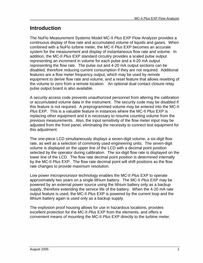
Introduction The NuFlo Measurement Systems Model MC-II Plus EXP Flow Analyzer provides a continuous display of flow rate and accumulated volume of liquids and gases. When combined with a NuFlo turbine meter, the MC-II Plus EXP becomes an accurate system for the measurement and display of instantaneous flow rate and volume. In addition, the MC-II Plus EXP standard circuitry provides a scaled pulse output representing an increment in volume for each pulse and a 4-20 mA output representing the flow rate. The pulse out and 4-20 mA output sections can be disabled, therefore reducing current consumption if they are not required. Additional features are a flow meter frequency output, which may be used by remote equipment to derive flow rate and volume, and a reset feature that allows resetting of the volume to zero from a remote location. An optional dual contact closure relay pulse output board is also available. A security access code prevents unauthorized personnel from altering the calibration or accumulated volume data in the instrument. The security code may be disabled if this feature is not required. A preprogrammed volume may be entered into the MC-II Plus EXP. This is a valuable feature in instances where the MC-II Plus EXP is replacing other equipment and it is necessary to resume counting volume from the previous measurements. Also, the input sensitivity of the flow meter input may be adjusted from the front panel, eliminating the necessity to connect test equipment for this adjustment. The one-piece LCD simultaneously displays a seven-digit volume, a six-digit flow rate, as well as a selection of commonly used engineering units. The seven-digit volume is displayed on the upper line of the LCD with a decimal point position selected by the operator during calibration. The six-digit flow rate is displayed on the lower line of the LCD. The flow rate decimal point position is determined internally by the MC-II Plus EXP. The flow rate decimal point will shift positions as the flow rate changes to provide maximum resolution. Low power microprocessor technology enables the MC-II Plus EXP to operate approximately two years on a single lithium battery. The MC-II Plus EXP may be powered by an external power source using the lithium battery only as a backup supply, therefore extending the service life of the battery. When the 4-20 mA rate output feature is used, the MC-II Plus EXP is powered by the current loop and the lithium battery again is used only as a backup supply. The explosion proof housing allows for use in hazardous locations, provides excellent protection for the MC-II Plus EXP from the elements, and offers a convenient means of mounting the MC-II Plus EXP directly to the turbine meter.
MC-II Plus EXP Flow Analyzer
2 August 2005
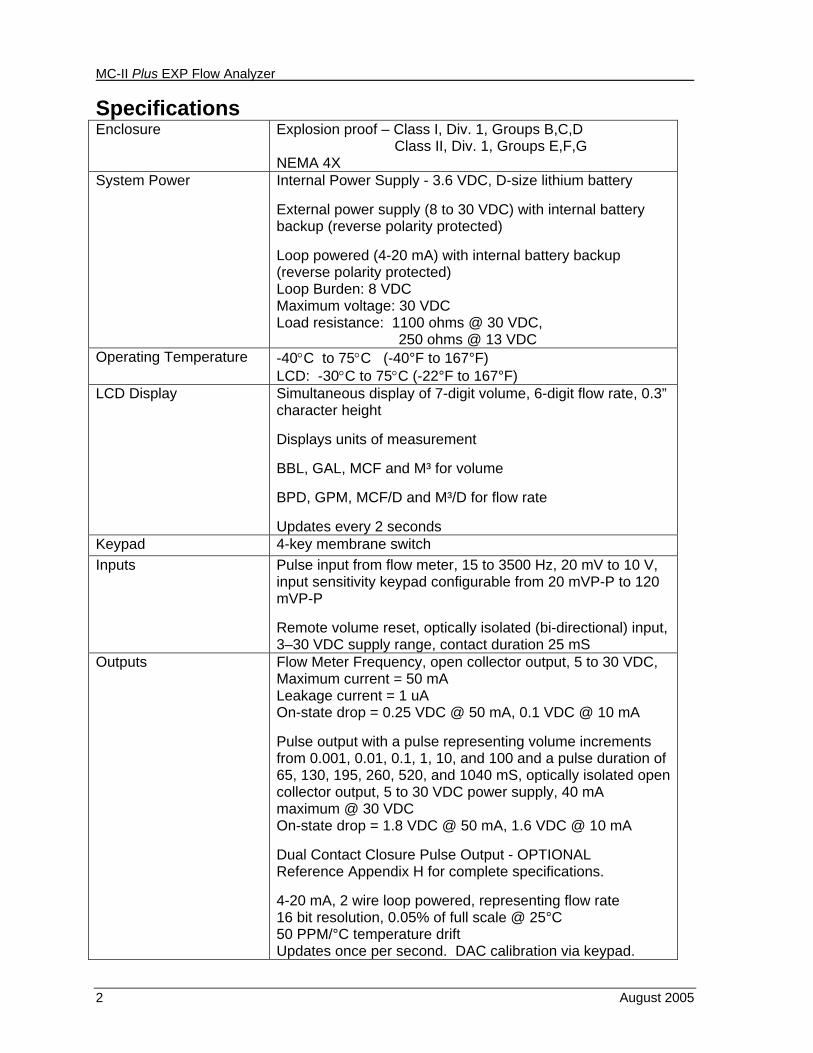
Specifications Enclosure Explosion proof – Class I, Div. 1, Groups B,C,D
Class II, Div. 1, Groups E,F,G NEMA 4X
System Power Internal Power Supply - 3.6 VDC, D-size lithium battery External power supply (8 to 30 VDC) with internal battery backup (reverse polarity protected) Loop powered (4-20 mA) with internal battery backup (reverse polarity protected) Loop Burden: 8 VDC Maximum voltage: 30 VDC Load resistance: 1100 ohms @ 30 VDC, 250 ohms @ 13 VDC
Operating Temperature -40°C to 75°C (-40°F to 167°F) LCD: -30°C to 75°C (-22°F to 167°F)
LCD Display Simultaneous display of 7-digit volume, 6-digit flow rate, 0.3” character height Displays units of measurement BBL, GAL, MCF and M³ for volume BPD, GPM, MCF/D and M³/D for flow rate Updates every 2 seconds
Keypad 4-key membrane switch Inputs Pulse input from flow meter, 15 to 3500 Hz, 20 mV to 10 V,
input sensitivity keypad configurable from 20 mVP-P to 120 mVP-P Remote volume reset, optically isolated (bi-directional) input, 3–30 VDC supply range, contact duration 25 mS
Outputs Flow Meter Frequency, open collector output, 5 to 30 VDC, Maximum current = 50 mA Leakage current = 1 uA On-state drop = 0.25 VDC @ 50 mA, 0.1 VDC @ 10 mA Pulse output with a pulse representing volume increments from 0.001, 0.01, 0.1, 1, 10, and 100 and a pulse duration of 65, 130, 195, 260, 520, and 1040 mS, optically isolated open collector output, 5 to 30 VDC power supply, 40 mA maximum @ 30 VDC On-state drop = 1.8 VDC @ 50 mA, 1.6 VDC @ 10 mA Dual Contact Closure Pulse Output - OPTIONAL Reference Appendix H for complete specifications. 4-20 mA, 2 wire loop powered, representing flow rate 16 bit resolution, 0.05% of full scale @ 25°C 50 PPM/°C temperature drift Updates once per second. DAC calibration via keypad.
MC-II Plus EXP Flow Analyzer
August 2005 3
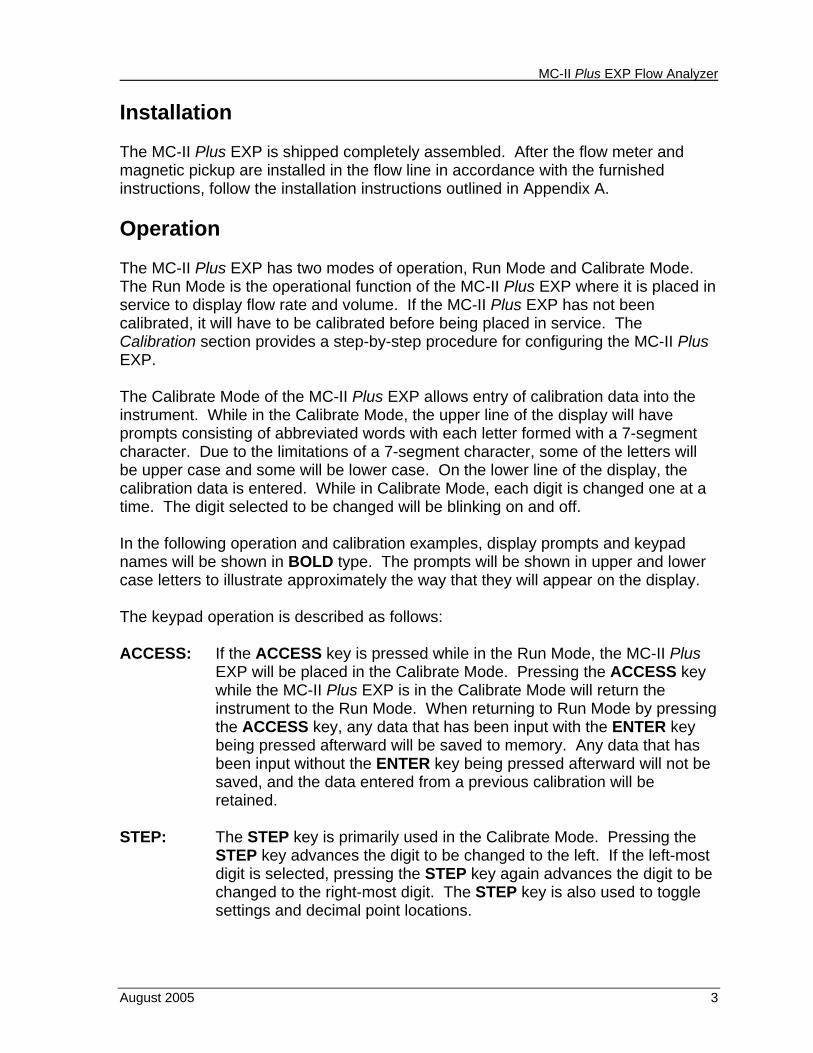
Installation The MC-II Plus EXP is shipped completely assembled. After the flow meter and magnetic pickup are installed in the flow line in accordance with the furnished instructions, follow the installation instructions outlined in Appendix A. Operation The MC-II Plus EXP has two modes of operation, Run Mode and Calibrate Mode. The Run Mode is the operational function of the MC-II Plus EXP where it is placed in service to display flow rate and volume. If the MC-II Plus EXP has not been calibrated, it will have to be calibrated before being placed in service. The Calibration section provides a step-by-step procedure for configuring the MC-II Plus EXP. The Calibrate Mode of the MC-II Plus EXP allows entry of calibration data into the instrument. While in the Calibrate Mode, the upper line of the display will have prompts consisting of abbreviated words with each letter formed with a 7-segment character. Due to the limitations of a 7-segment character, some of the letters will be upper case and some will be lower case. On the lower line of the display, the calibration data is entered. While in Calibrate Mode, each digit is changed one at a time. The digit selected to be changed will be blinking on and off. In the following operation and calibration examples, display prompts and keypad names will be shown in BOLD type. The prompts will be shown in upper and lower case letters to illustrate approximately the way that they will appear on the display. The keypad operation is described as follows: ACCESS: If the ACCESS key is pressed while in the Run Mode, the MC-II Plus
EXP will be placed in the Calibrate Mode. Pressing the ACCESS key while the MC-II Plus EXP is in the Calibrate Mode will return the instrument to the Run Mode. When returning to Run Mode by pressing the ACCESS key, any data that has been input with the ENTER key being pressed afterward will be saved to memory. Any data that has been input without the ENTER key being pressed afterward will not be saved, and the data entered from a previous calibration will be retained.
STEP: The STEP key is primarily used in the Calibrate Mode. Pressing the
STEP key advances the digit to be changed to the left. If the left-most digit is selected, pressing the STEP key again advances the digit to be changed to the right-most digit. The STEP key is also used to toggle settings and decimal point locations.
MC-II Plus EXP Flow Analyzer
4 August 2005
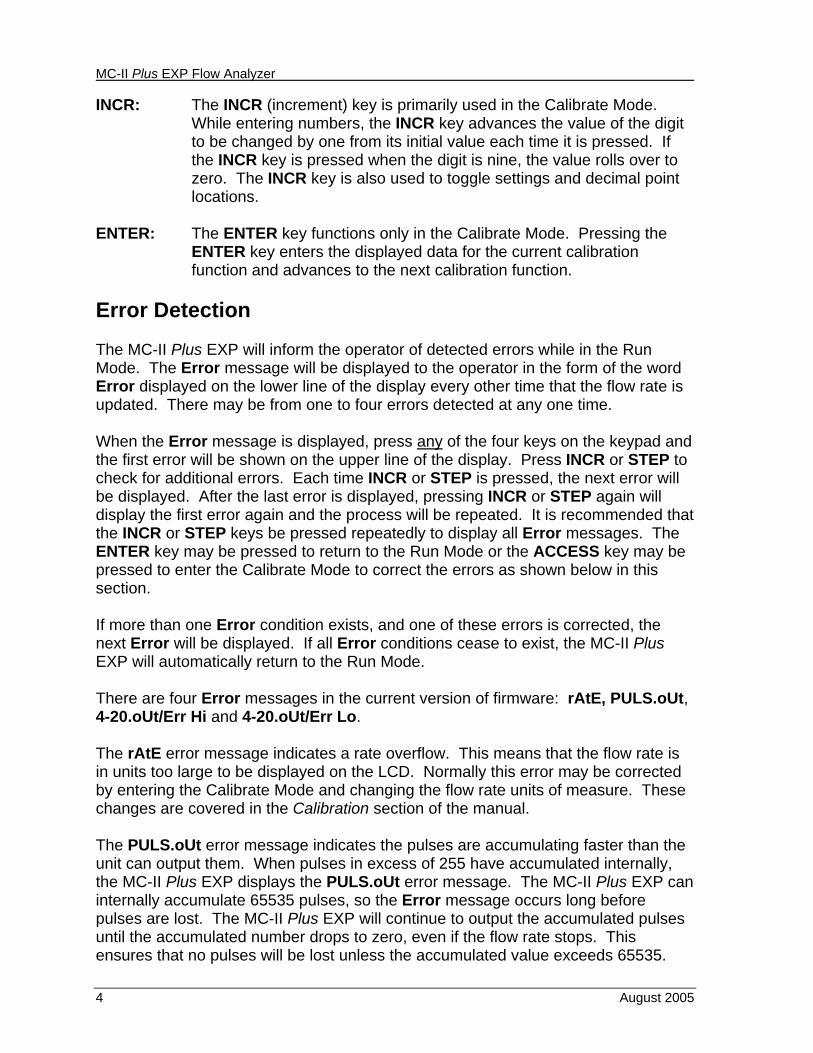
INCR: The INCR (increment) key is primarily used in the Calibrate Mode. While entering numbers, the INCR key advances the value of the digit to be changed by one from its initial value each time it is pressed. If the INCR key is pressed when the digit is nine, the value rolls over to zero. The INCR key is also used to toggle settings and decimal point locations.
ENTER: The ENTER key functions only in the Calibrate Mode. Pressing the
ENTER key enters the displayed data for the current calibration function and advances to the next calibration function.
Error Detection The MC-II Plus EXP will inform the operator of detected errors while in the Run Mode. The Error message will be displayed to the operator in the form of the word Error displayed on the lower line of the display every other time that the flow rate is updated. There may be from one to four errors detected at any one time. When the Error message is displayed, press any of the four keys on the keypad and the first error will be shown on the upper line of the display. Press INCR or STEP to check for additional errors. Each time INCR or STEP is pressed, the next error will be displayed. After the last error is displayed, pressing INCR or STEP again will display the first error again and the process will be repeated. It is recommended that the INCR or STEP keys be pressed repeatedly to display all Error messages. The ENTER key may be pressed to return to the Run Mode or the ACCESS key may be pressed to enter the Calibrate Mode to correct the errors as shown below in this section. If more than one Error condition exists, and one of these errors is corrected, the next Error will be displayed. If all Error conditions cease to exist, the MC-II Plus EXP will automatically return to the Run Mode. There are four Error messages in the current version of firmware: rAtE, PULS.oUt, 4-20.oUt/Err Hi and 4-20.oUt/Err Lo. The rAtE error message indicates a rate overflow. This means that the flow rate is in units too large to be displayed on the LCD. Normally this error may be corrected by entering the Calibrate Mode and changing the flow rate units of measure. These changes are covered in the Calibration section of the manual. The PULS.oUt error message indicates the pulses are accumulating faster than the unit can output them. When pulses in excess of 255 have accumulated internally, the MC-II Plus EXP displays the PULS.oUt error message. The MC-II Plus EXP can internally accumulate 65535 pulses, so the Error message occurs long before pulses are lost. The MC-II Plus EXP will continue to output the accumulated pulses until the accumulated number drops to zero, even if the flow rate stops. This ensures that no pulses will be lost unless the accumulated value exceeds 65535.
MC-II Plus EXP Flow Analyzer
August 2005 5
Normally this error may be corrected by entering the Calibrate Mode and selecting a larger pulse output scale factor and/or a shorter pulse width duration. These changes are covered in the Configuring Pulse Output section of the manual. The 4-20.oUt/Err Hi error message indicates the flow rate has exceeded the full-scale calibrated flow rate setting to the point that the current output has exceeded 22 mA. The Error message appears on the lower line of the display only during the time that the condition exists. When any key is pressed during the error condition, the 4-20.oUt message appears on the upper line of the display and the Err Hi message appears on the lower line of the display. This error may be caused by excessive flow rate or the full scale flow rate calibration point being set too low for normal operating conditions. Changing the full-scale flow rate calibration point is covered in Configuring the 4-20 mA Rate Output section of the manual. The 4-20.oUt/Err Lo error message indicates the flow rate is below the calibrated low flow rate setting. The output current will be 3.9 mA. The Error message appears on the lower line of the display only during the time that the condition exists. When any key is pressed during the error condition, the 4-20.oUt message appears on the upper line of the display and the Err Lo message appears on the lower line of the display. This error may be caused by the flow rate falling below the low flow rate calibration point or the low flow rate calibration point being set too high for normal operating conditions. Changing the low flow rate calibration point is covered in Configuring the 4-20 mA Rate Output section of the manual. Calibration Calibration of the MC-II Plus EXP is a simple matter of entering the necessary parameters for calibration into the instrument using the keypad. The user friendly prompts and the ability of the MC-II Plus EXP microprocessor circuitry to calculate the divisor for volume calculation and the rate multiplier for flow rate calculation make calibrating the instrument a simple process. The steps followed to calibrate the MC-II Plus EXP depend on whether liquid or gas is being measured and the units of measure. There are four categories of measurement: • Liquid Measurement Using Preprogrammed Units of Measure • Gas Measurement Using Preprogrammed Units of Measure • Liquid Measurement Using a Calculated Divisor and Rate Multiplier • Gas Measurement Using a Calculated Divisor and Rate Multiplier The steps followed to calibrate the MC-II Plus EXP for each of these categories are outlined in the following sections.
MC-II Plus EXP Flow Analyzer
6 August 2005
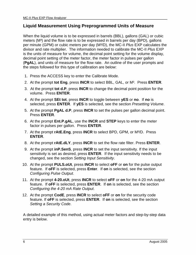
Liquid Measurement Using Preprogrammed Units of Measure When the liquid volume is to be expressed in barrels (BBL), gallons (GAL) or cubic meters (M³) and the flow rate is to be expressed in barrels per day (BPD), gallons per minute (GPM) or cubic meters per day (M³/D), the MC-II Plus EXP calculates the divisor and rate multiplier. The information needed to calibrate the MC-II Plus EXP is the units of measure for volume, the decimal point setting for the volume display, decimal point setting of the meter factor, the meter factor in pulses per gallon (PgAL), and units of measure for the flow rate. An outline of the user prompts and the steps followed for this type of calibration are below: 1. Press the ACCESS key to enter the Calibrate Mode. 2. At the prompt tot Eng, press INCR to select BBL, GAL, or M³. Press ENTER. 3. At the prompt tot d.P, press INCR to change the decimal point position for the
volume. Press ENTER. 4. At the prompt SEt tot, press INCR to toggle between yES or no. If no is
selected, press ENTER. If yES is selected, see the section Presetting Volume. 5. At the prompt PgAL d.P, press INCR to set the pulses per gallon decimal point.
Press ENTER. 6. At the prompt Ent.P.gAL, use the INCR and STEP keys to enter the meter
factor in pulses per gallon. Press ENTER. 7. At the prompt rAtE.Eng, press INCR to select BPD, GPM, or M³/D. Press
ENTER. 8. At the prompt rAtE.dLY, press INCR to set the flow rate filter. Press ENTER. 9. At the prompt inP.SenS, press INCR to set the input sensitivity. If the input
sensitivity is set as desired, press ENTER. If the input sensitivity needs to be changed, see the section Setting Input Sensitivity.
10. At the prompt PULS.oUt, press INCR to select oFF or on for the pulse output feature. If oFF is selected, press Enter. If on is selected, see the section Configuring Pulse Output.
11. At the prompt 4-20.oUt, press INCR to select oFF or on for the 4-20 mA output feature. If oFF is selected, press ENTER. If on is selected, see the section Configuring the 4-20 mA Rate Output.
12. At the prompt CodE, press INCR to select oFF or on for the security code feature. If oFF is selected, press ENTER. If on is selected, see the section Setting a Security Code.
A detailed example of this method, using actual meter factors and step-by-step data entry is below.
MC-II Plus EXP Flow Analyzer
August 2005 7
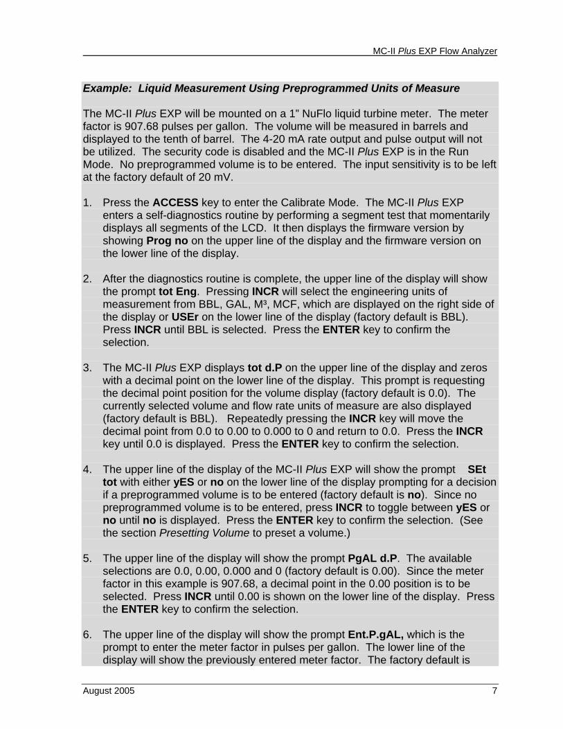
Example: Liquid Measurement Using Preprogrammed Units of Measure The MC-II Plus EXP will be mounted on a 1” NuFlo liquid turbine meter. The meter factor is 907.68 pulses per gallon. The volume will be measured in barrels and displayed to the tenth of barrel. The 4-20 mA rate output and pulse output will not be utilized. The security code is disabled and the MC-II Plus EXP is in the Run Mode. No preprogrammed volume is to be entered. The input sensitivity is to be left at the factory default of 20 mV. 1. Press the ACCESS key to enter the Calibrate Mode. The MC-II Plus EXP
enters a self-diagnostics routine by performing a segment test that momentarily displays all segments of the LCD. It then displays the firmware version by showing Prog no on the upper line of the display and the firmware version on the lower line of the display.
2. After the diagnostics routine is complete, the upper line of the display will show the prompt tot Eng. Pressing INCR will select the engineering units of measurement from BBL, GAL, M³, MCF, which are displayed on the right side of the display or USEr on the lower line of the display (factory default is BBL). Press INCR until BBL is selected. Press the ENTER key to confirm the selection.
3. The MC-II Plus EXP displays tot d.P on the upper line of the display and zeros with a decimal point on the lower line of the display. This prompt is requesting the decimal point position for the volume display (factory default is 0.0). The currently selected volume and flow rate units of measure are also displayed (factory default is BBL). Repeatedly pressing the INCR key will move the decimal point from 0.0 to 0.00 to 0.000 to 0 and return to 0.0. Press the INCR key until 0.0 is displayed. Press the ENTER key to confirm the selection.
4. The upper line of the display of the MC-II Plus EXP will show the prompt SEt tot with either yES or no on the lower line of the display prompting for a decision if a preprogrammed volume is to be entered (factory default is no). Since no preprogrammed volume is to be entered, press INCR to toggle between yES or no until no is displayed. Press the ENTER key to confirm the selection. (See the section Presetting Volume to preset a volume.)
5. The upper line of the display will show the prompt PgAL d.P. The available
selections are 0.0, 0.00, 0.000 and 0 (factory default is 0.00). Since the meter factor in this example is 907.68, a decimal point in the 0.00 position is to be selected. Press INCR until 0.00 is shown on the lower line of the display. Press the ENTER key to confirm the selection.
6. The upper line of the display will show the prompt Ent.P.gAL, which is the
prompt to enter the meter factor in pulses per gallon. The lower line of the display will show the previously entered meter factor. The factory default is
MC-II Plus EXP Flow Analyzer
8 August 2005
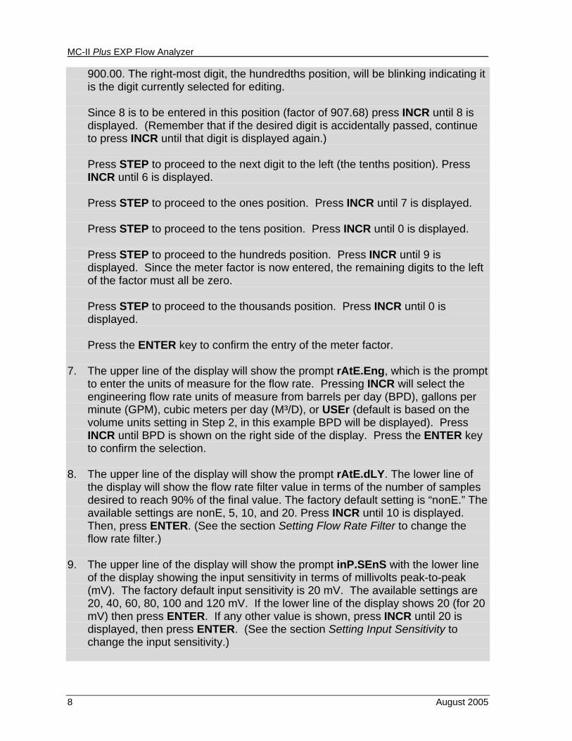
900.00. The right-most digit, the hundredths position, will be blinking indicating it is the digit currently selected for editing. Since 8 is to be entered in this position (factor of 907.68) press INCR until 8 is displayed. (Remember that if the desired digit is accidentally passed, continue to press INCR until that digit is displayed again.) Press STEP to proceed to the next digit to the left (the tenths position). Press INCR until 6 is displayed. Press STEP to proceed to the ones position. Press INCR until 7 is displayed. Press STEP to proceed to the tens position. Press INCR until 0 is displayed. Press STEP to proceed to the hundreds position. Press INCR until 9 is displayed. Since the meter factor is now entered, the remaining digits to the left of the factor must all be zero. Press STEP to proceed to the thousands position. Press INCR until 0 is displayed. Press the ENTER key to confirm the entry of the meter factor.
7. The upper line of the display will show the prompt rAtE.Eng, which is the prompt
to enter the units of measure for the flow rate. Pressing INCR will select the engineering flow rate units of measure from barrels per day (BPD), gallons per minute (GPM), cubic meters per day (M³/D), or USEr (default is based on the volume units setting in Step 2, in this example BPD will be displayed). Press INCR until BPD is shown on the right side of the display. Press the ENTER key to confirm the selection.
8. The upper line of the display will show the prompt rAtE.dLY. The lower line of
the display will show the flow rate filter value in terms of the number of samples desired to reach 90% of the final value. The factory default setting is “nonE.” The available settings are nonE, 5, 10, and 20. Press INCR until 10 is displayed. Then, press ENTER. (See the section Setting Flow Rate Filter to change the flow rate filter.)
9. The upper line of the display will show the prompt inP.SEnS with the lower line
of the display showing the input sensitivity in terms of millivolts peak-to-peak (mV). The factory default input sensitivity is 20 mV. The available settings are 20, 40, 60, 80, 100 and 120 mV. If the lower line of the display shows 20 (for 20 mV) then press ENTER. If any other value is shown, press INCR until 20 is displayed, then press ENTER. (See the section Setting Input Sensitivity to change the input sensitivity.)
MC-II Plus EXP Flow Analyzer
August 2005 9
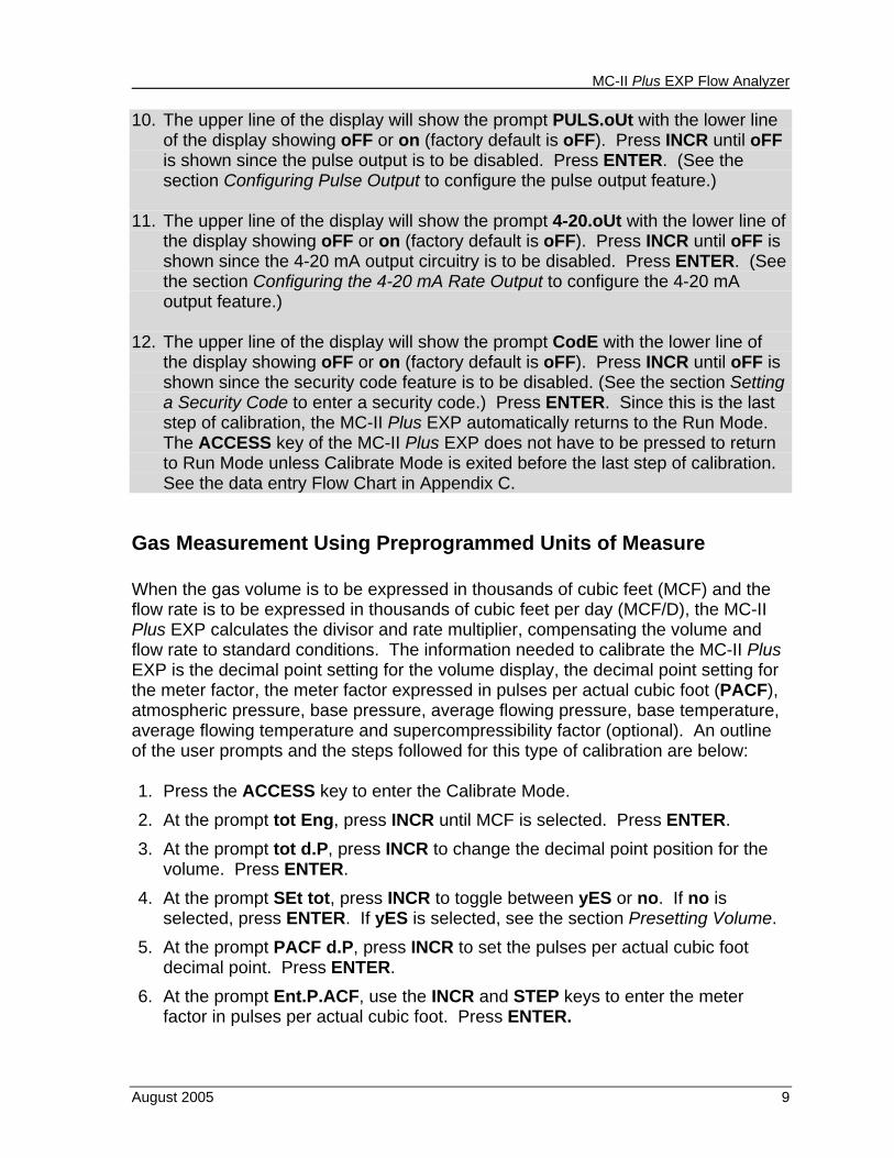
10. The upper line of the display will show the prompt PULS.oUt with the lower line of the display showing oFF or on (factory default is oFF). Press INCR until oFF is shown since the pulse output is to be disabled. Press ENTER. (See the section Configuring Pulse Output to configure the pulse output feature.)
11. The upper line of the display will show the prompt 4-20.oUt with the lower line of
the display showing oFF or on (factory default is oFF). Press INCR until oFF is shown since the 4-20 mA output circuitry is to be disabled. Press ENTER. (See the section Configuring the 4-20 mA Rate Output to configure the 4-20 mA output feature.)
12. The upper line of the display will show the prompt CodE with the lower line of
the display showing oFF or on (factory default is oFF). Press INCR until oFF is shown since the security code feature is to be disabled. (See the section Setting a Security Code to enter a security code.) Press ENTER. Since this is the last step of calibration, the MC-II Plus EXP automatically returns to the Run Mode. The ACCESS key of the MC-II Plus EXP does not have to be pressed to return to Run Mode unless Calibrate Mode is exited before the last step of calibration. See the data entry Flow Chart in Appendix C.
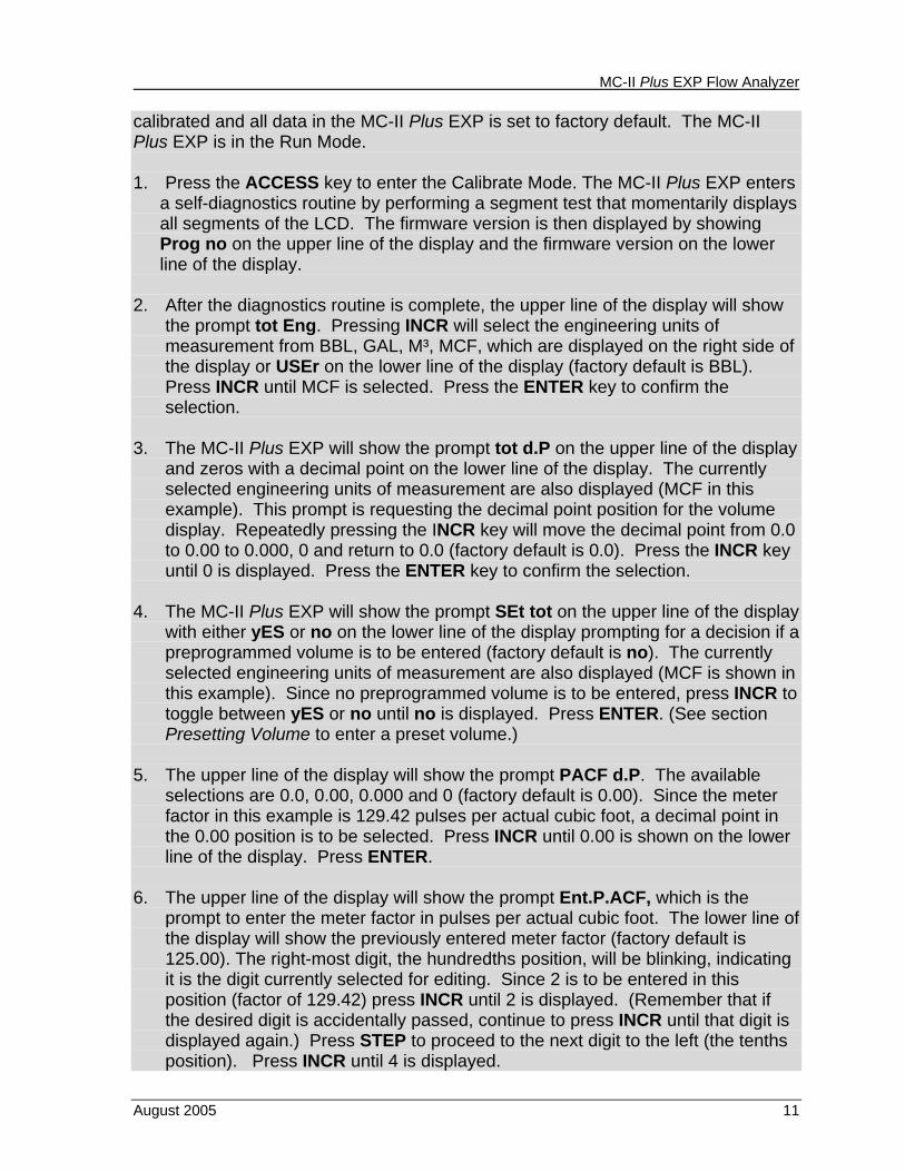
Gas Measurement Using Preprogrammed Units of Measure When the gas volume is to be expressed in thousands of cubic feet (MCF) and the flow rate is to be expressed in thousands of cubic feet per day (MCF/D), the MC-II Plus EXP calculates the divisor and rate multiplier, compensating the volume and flow rate to standard conditions. The information needed to calibrate the MC-II Plus EXP is the decimal point setting for the volume display, the decimal point setting for the meter factor, the meter factor expressed in pulses per actual cubic foot (PACF), atmospheric pressure, base pressure, average flowing pressure, base temperature, average flowing temperature and supercompressibility factor (optional). An outline of the user prompts and the steps followed for this type of calibration are below: 1. Press the ACCESS key to enter the Calibrate Mode. 2. At the prompt tot Eng, press INCR until MCF is selected. Press ENTER. 3. At the prompt tot d.P, press INCR to change the decimal point position for the
volume. Press ENTER. 4. At the prompt SEt tot, press INCR to toggle between yES or no. If no is
selected, press ENTER. If yES is selected, see the section Presetting Volume. 5. At the prompt PACF d.P, press INCR to set the pulses per actual cubic foot
decimal point. Press ENTER. 6. At the prompt Ent.P.ACF, use the INCR and STEP keys to enter the meter
factor in pulses per actual cubic foot. Press ENTER.

MC-II Plus EXP Flow Analyzer
10 August 2005
7. At the prompt bAro.Psi, use the INCR and STEP keys to enter the barometric pressure in pounds per square inch absolute (PSIA). Press ENTER.
8. At the prompt bASE.Psi, use the INCR and STEP keys to enter the base pressure in PSIA. Press ENTER.
9. At the prompt Ent.Psig, use the INCR and STEP keys to enter the average flowing pressure in pounds per square inch (PSIG). Press ENTER.
10. At the prompt bASE F, use the INCR and STEP keys to enter the base temperature in degrees Fahrenheit (F). Press ENTER.
11. At the prompt Ent F, use the INCR and STEP keys to enter the average flowing temperature in degrees F. Press ENTER.
12. At the prompt Ent FPv, use the INCR and STEP keys to enter the supercompressibility factor. Press ENTER.
13. At the prompt rAtE.dLY, press INCR to set the flow rate filter. Press ENTER. 14. At the prompt inP.SenS, press INCR to set the input sensitivity. If the input
sensitivity is set as desired, press ENTER. If the input sensitivity needs to be changed, see the section Setting Input Sensitivity.
15. At the prompt PULS.oUt, press INCR to select oFF or on for the pulse output feature. If oFF is selected, press ENTER. If on is selected, see the section Configuring Pulse Output.
16. At the prompt 4-20.oUt, press INCR to select oFF or on for the 4-20 mA output feature. If oFF is selected, press ENTER. If on is selected, see the section Configuring the 4-20 mA Rate Output.
17. At the prompt CodE, press INCR to select oFF or on for the security code feature. If oFF is selected, press ENTER. If on is selected, see the section Setting a Security Code.
A detailed example of this method, using actual meter factors and step-by-step data entry is below. Example: Gas Measurement Using Preprogrammed Units of Measure The MC-II Plus EXP will be mounted on a 2” NuFlo standard range gas turbine meter. The meter factor is 129.42 pulses per actual cubic foot. The volume units of measure will be in thousands of standard cubic feet (MCF) and the flow rate units of measure will be in thousands of standard cubic feet per day (MCF/D). The average flowing pressure is 120 PSIG. The average flowing temperature is 50 degrees Fahrenheit. The base pressure is 14.73 PSIG and the base temperature is 60 degrees Fahrenheit. The atmospheric pressure is not known but the elevation of the installation is 1000 feet above sea level. The 4-20 mA output, pulse output and security code are to be disabled. The input sensitivity is to be left at 20 mV and no preprogrammed volume is to be entered. The MC-II Plus EXP has not been
MC-II Plus EXP Flow Analyzer
August 2005 11
calibrated and all data in the MC-II Plus EXP is set to factory default. The MC-II Plus EXP is in the Run Mode. 1. Press the ACCESS key to enter the Calibrate Mode. The MC-II Plus EXP enters
a self-diagnostics routine by performing a segment test that momentarily displays all segments of the LCD. The firmware version is then displayed by showing Prog no on the upper line of the display and the firmware version on the lower line of the display.
2. After the diagnostics routine is complete, the upper line of the display will show
the prompt tot Eng. Pressing INCR will select the engineering units of measurement from BBL, GAL, M³, MCF, which are displayed on the right side of the display or USEr on the lower line of the display (factory default is BBL). Press INCR until MCF is selected. Press the ENTER key to confirm the selection.
3. The MC-II Plus EXP will show the prompt tot d.P on the upper line of the display
and zeros with a decimal point on the lower line of the display. The currently selected engineering units of measurement are also displayed (MCF in this example). This prompt is requesting the decimal point position for the volume display. Repeatedly pressing the INCR key will move the decimal point from 0.0 to 0.00 to 0.000, 0 and return to 0.0 (factory default is 0.0). Press the INCR key until 0 is displayed. Press the ENTER key to confirm the selection.
4. The MC-II Plus EXP will show the prompt SEt tot on the upper line of the display
with either yES or no on the lower line of the display prompting for a decision if a preprogrammed volume is to be entered (factory default is no). The currently selected engineering units of measurement are also displayed (MCF is shown in this example). Since no preprogrammed volume is to be entered, press INCR to toggle between yES or no until no is displayed. Press ENTER. (See section Presetting Volume to enter a preset volume.)
5. The upper line of the display will show the prompt PACF d.P. The available selections are 0.0, 0.00, 0.000 and 0 (factory default is 0.00). Since the meter factor in this example is 129.42 pulses per actual cubic foot, a decimal point in the 0.00 position is to be selected. Press INCR until 0.00 is shown on the lower line of the display. Press ENTER.
6. The upper line of the display will show the prompt Ent.P.ACF, which is the
prompt to enter the meter factor in pulses per actual cubic foot. The lower line of the display will show the previously entered meter factor (factory default is 125.00). The right-most digit, the hundredths position, will be blinking, indicating it is the digit currently selected for editing. Since 2 is to be entered in this position (factor of 129.42) press INCR until 2 is displayed. (Remember that if the desired digit is accidentally passed, continue to press INCR until that digit is displayed again.) Press STEP to proceed to the next digit to the left (the tenths position). Press INCR until 4 is displayed.
MC-II Plus EXP Flow Analyzer
12 August 2005
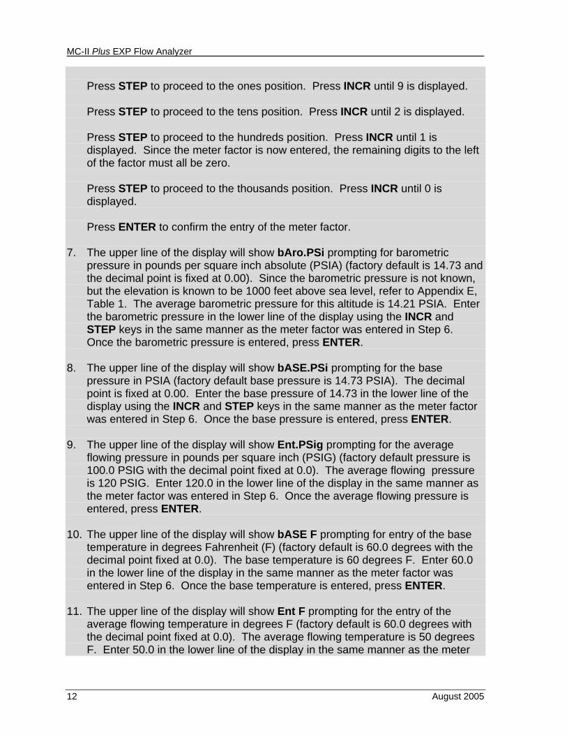
Press STEP to proceed to the ones position. Press INCR until 9 is displayed. Press STEP to proceed to the tens position. Press INCR until 2 is displayed. Press STEP to proceed to the hundreds position. Press INCR until 1 is displayed. Since the meter factor is now entered, the remaining digits to the left of the factor must all be zero.
Press STEP to proceed to the thousands position. Press INCR until 0 is
displayed.
Press ENTER to confirm the entry of the meter factor.
7. The upper line of the display will show bAro.PSi prompting for barometric pressure in pounds per square inch absolute (PSIA) (factory default is 14.73 and the decimal point is fixed at 0.00). Since the barometric pressure is not known, but the elevation is known to be 1000 feet above sea level, refer to Appendix E, Table 1. The average barometric pressure for this altitude is 14.21 PSIA. Enter the barometric pressure in the lower line of the display using the INCR and STEP keys in the same manner as the meter factor was entered in Step 6. Once the barometric pressure is entered, press ENTER.
8. The upper line of the display will show bASE.PSi prompting for the base
pressure in PSIA (factory default base pressure is 14.73 PSIA). The decimal point is fixed at 0.00. Enter the base pressure of 14.73 in the lower line of the display using the INCR and STEP keys in the same manner as the meter factor was entered in Step 6. Once the base pressure is entered, press ENTER.
9. The upper line of the display will show Ent.PSig prompting for the average
flowing pressure in pounds per square inch (PSIG) (factory default pressure is 100.0 PSIG with the decimal point fixed at 0.0). The average flowing pressure is 120 PSIG. Enter 120.0 in the lower line of the display in the same manner as the meter factor was entered in Step 6. Once the average flowing pressure is entered, press ENTER.
10. The upper line of the display will show bASE F prompting for entry of the base
temperature in degrees Fahrenheit (F) (factory default is 60.0 degrees with the decimal point fixed at 0.0). The base temperature is 60 degrees F. Enter 60.0 in the lower line of the display in the same manner as the meter factor was entered in Step 6. Once the base temperature is entered, press ENTER.
11. The upper line of the display will show Ent F prompting for the entry of the
average flowing temperature in degrees F (factory default is 60.0 degrees with the decimal point fixed at 0.0). The average flowing temperature is 50 degrees F. Enter 50.0 in the lower line of the display in the same manner as the meter
MC-II Plus EXP Flow Analyzer
August 2005 13
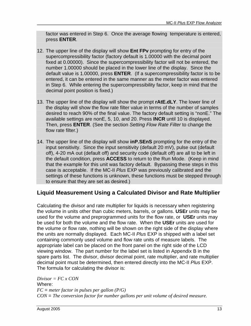
factor was entered in Step 6. Once the average flowing temperature is entered, press ENTER.
12. The upper line of the display will show Ent FPv prompting for entry of the
supercompressibility factor (factory default is 1.00000 with the decimal point fixed at 0.00000). Since the supercompressibility factor will not be entered, the number 1.00000 should be placed in the lower line of the display. Since the default value is 1.00000, press ENTER. (If a supercompressibility factor is to be entered, it can be entered in the same manner as the meter factor was entered in Step 6. While entering the supercompressibility factor, keep in mind that the decimal point position is fixed.)
13. The upper line of the display will show the prompt rAtE.dLY. The lower line of
the display will show the flow rate filter value in terms of the number of samples desired to reach 90% of the final value. The factory default setting is “nonE.” The available settings are nonE, 5, 10, and 20. Press INCR until 10 is displayed. Then, press ENTER. (See the section Setting Flow Rate Filter to change the flow rate filter.)
14. The upper line of the display will show inP.SEnS prompting for the entry of the
input sensitivity. Since the input sensitivity (default 20 mV), pulse out (default off), 4-20 mA out (default off) and security code (default off) are all to be left in the default condition, press ACCESS to return to the Run Mode. (Keep in mind that the example for this unit was factory default. Bypassing these steps in this case is acceptable. If the MC-II Plus EXP was previously calibrated and the settings of these functions is unknown, these functions must be stepped through to ensure that they are set as desired.)
Liquid Measurement Using a Calculated Divisor and Rate Multiplier Calculating the divisor and rate multiplier for liquids is necessary when registering the volume in units other than cubic meters, barrels, or gallons. USEr units may be used for the volume and preprogrammed units for the flow rate, or USEr units may be used for both the volume and the flow rate. When the USEr units are used for the volume or flow rate, nothing will be shown on the right side of the display where the units are normally displayed. Each MC-II Plus EXP is shipped with a label set containing commonly used volume and flow rate units of measure labels. The appropriate label can be placed on the front panel on the right side of the LCD viewing window. The part number for the label set is listed in Appendix B in the spare parts list. The divisor, divisor decimal point, rate multiplier, and rate multiplier decimal point must be determined, then entered directly into the MC-II Plus EXP. The formula for calculating the divisor is: Divisor = FC x CON Where: FC = meter factor in pulses per gallon (P/G) CON = The conversion factor for number gallons per unit volume of desired measure.
MC-II Plus EXP Flow Analyzer
14 August 2005
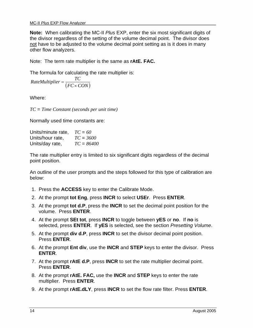
Note: When calibrating the MC-II Plus EXP, enter the six most significant digits of the divisor regardless of the setting of the volume decimal point. The divisor does not have to be adjusted to the volume decimal point setting as is it does in many other flow analyzers. Note: The term rate multiplier is the same as rAtE. FAC. The formula for calculating the rate multiplier is:
( )CONFCTClierRateMultip×
=
Where: TC = Time Constant (seconds per unit time) Normally used time constants are: Units/minute rate, TC = 60 Units/hour rate, TC = 3600 Units/day rate, TC = 86400 The rate multiplier entry is limited to six significant digits regardless of the decimal point position. An outline of the user prompts and the steps followed for this type of calibration are below: 1. Press the ACCESS key to enter the Calibrate Mode. 2. At the prompt tot Eng, press INCR to select USEr. Press ENTER. 3. At the prompt tot d.P, press the INCR to set the decimal point position for the
volume. Press ENTER. 4. At the prompt SEt tot, press INCR to toggle between yES or no. If no is
selected, press ENTER. If yES is selected, see the section Presetting Volume. 5. At the prompt div d.P, press INCR to set the divisor decimal point position.
Press ENTER. 6. At the prompt Ent div, use the INCR and STEP keys to enter the divisor. Press
ENTER. 7. At the prompt rAtE d.P, press INCR to set the rate multiplier decimal point.
Press ENTER. 8. At the prompt rAtE. FAC, use the INCR and STEP keys to enter the rate
multiplier. Press ENTER. 9. At the prompt rAtE.dLY, press INCR to set the flow rate filter. Press ENTER.
MC-II Plus EXP Flow Analyzer
August 2005 15
10. At the prompt inP.SenS, press INCR to set the input sensitivity. If the input sensitivity is set as desired, press ENTER. If the input sensitivity needs to be changed, see the section Setting Input Sensitivity.
11. At the prompt PULS.oUt, press INCR to select oFF or on for the pulse output feature. If oFF is selected, press ENTER. If on is selected, see the section Configuring Pulse Output.
13. At the prompt 4-20.oUt, press INCR to select oFF or on for the 4-20 mA output feature. If oFF is selected, press ENTER. If on is selected, see the section Configuring the 4-20 mA Rate Output.
14. At the prompt CodE, press INCR to select oFF or on for the security code feature. If oFF is selected, press ENTER. If on is selected, see the section Setting a Security Code.
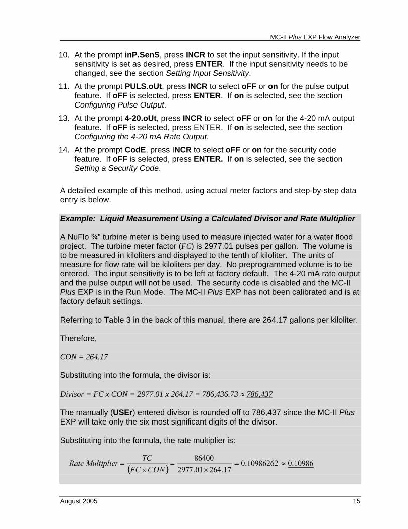
A detailed example of this method, using actual meter factors and step-by-step data entry is below. Example: Liquid Measurement Using a Calculated Divisor and Rate Multiplier A NuFlo ¾” turbine meter is being used to measure injected water for a water flood project. The turbine meter factor (FC) is 2977.01 pulses per gallon. The volume is to be measured in kiloliters and displayed to the tenth of kiloliter. The units of measure for flow rate will be kiloliters per day. No preprogrammed volume is to be entered. The input sensitivity is to be left at factory default. The 4-20 mA rate output and the pulse output will not be used. The security code is disabled and the MC-II Plus EXP is in the Run Mode. The MC-II Plus EXP has not been calibrated and is at factory default settings. Referring to Table 3 in the back of this manual, there are 264.17 gallons per kiloliter. Therefore, CON = 264.17 Substituting into the formula, the divisor is: Divisor = FC x CON = 2977.01 x 264.17 = 786,436.73 ≈ 786,437 The manually (USEr) entered divisor is rounded off to 786,437 since the MC-II Plus EXP will take only the six most significant digits of the divisor. Substituting into the formula, the rate multiplier is:
MC-II Plus EXP Flow Analyzer
16 August 2005
Since the rate multiplier entry is limited from 0.00001 to 99999.9, it is rounded off to 0.10986 as shown above. Note: The rate multiplier in this example was determined by the time constant divided by the previously calculated divisor. This will save a calculation step when calculating the rate multiplier. This applies if the flow rate is in the same units as the volume (in this example kiloliters and kiloliters per day). When the volume and flow rate are to be in different units, such as kiloliters and liters per hour, the volume divisor and divisor for the rate multiplier must be calculated separately. The step-by-step entry of the calibration is as follows: 1. Press the ACCESS key to enter the Calibrate Mode. The MC-II Plus EXP enters
a self-diagnostics routine by performing a segment test that momentarily displays all segments of the LCD. The firmware version is then displayed by showing Prog no on the upper line of the display and the firmware version on the lower line of the display.
2. After the diagnostics routine is complete, the upper line of the display will show
the prompt tot Eng. Pressing INCR will select the engineering units of measurement from BBL, GAL, M³, MCF, which are displayed on the right side of the display or USEr on the lower line of the display (factory default is BBL). Press INCR until USEr is selected. Press ENTER to confirm the selection.
3. The MC-II Plus EXP show the prompt tot d.P on the upper line of the display
and zeros with a decimal point on the lower line of the display (factory default is 0.0). This prompt is requesting the decimal point position for the volume display. Repeatedly pressing the INCR key will move the decimal point from 0.0 to 0.00 to 0.000 to 0 and return to 0.0. Press the INCR key until 0.0 is displayed. Press the ENTER key.
4. The upper line of the display of the MC-II Plus EXP will show the prompt SEt tot
with either yES or no on the lower line of the display prompting for a decision if a preprogrammed volume is to be entered (factory default is no). Since no preprogrammed volume is to be entered, press INCR to toggle between yES or no until no is displayed. Press ENTER. (See the section Presetting Volume to preset a volume.)
5. The upper line of the display will show the prompt div d.P. The available
selections are 0.0, 0.00, 0.000 and 0 (factory default is 0.00). Since the divisor is 786,437, the 0 position, for whole number only, is selected. Press INCR until 0 is shown on the lower line of the display. Press ENTER.
6. The upper line of the display will show Ent div which is prompting for the entry of the divisor. The lower line of the display will show the previously entered meter factor (factory default is 230.00). The right-most digit (the ones position) will be blinking, indicating it is the digit currently selected for editing.
MC-II Plus EXP Flow Analyzer
August 2005 17
Remember to enter the divisor calculated for units of registration regardless of the location of the volume decimal point set in Step 3.
Since 7 is to be entered in this position (factor of 786,437) press INCR until 7 is displayed. (Remember that if the desired digit is accidentally passed, continue to press INCR until that digit is displayed again.)
Press STEP to proceed to the next digit (tens position). Press INCR until 3 is displayed. Press STEP to proceed to the next digit (hundreds position). Press INCR until 4 is displayed. Press STEP to proceed to the next digit (thousands position). Press INCR until 6 is displayed. Press STEP to proceed to the next digit (ten thousands position). Press INCR until 8 is displayed. Press STEP to proceed to the next digit (one hundred thousands position). Press INCR until 7 is displayed.
Press ENTER to confirm the entry of the divisor.
7. The upper line of the display will show rAtE d.P prompting for entry of the rate
multiplier decimal point. The selections for the rate multiplier decimal point are 0.0, 0.00, 0.000, 0.0000 and 0.00000 (factory default is 0.0). Press INCR until 0.00000 is displayed. Press ENTER.
8. The upper line of the display will show rAtE. FAC prompting for entry of the rate multiplier (factory default is 1.00000). Enter the rate multiplier (.10986) in the same manner as the divisor was entered in Step 6 and press ENTER.
9. The upper line of the display will show the prompt rAtE.dLY. The lower line of
the display will show the flow rate filter value in terms of the number of samples desired to reach 90% of the final value. The factory default setting is “nonE.” The available settings are nonE, 5, 10, and 20. Press INCR until 10 is displayed. Then, press ENTER. (See the section Setting Flow Rate Filter to change the flow rate filter.)
10. The upper line of the display will show inP.SEnS prompting for entry of the input
sensitivity in millivolts. Since the input sensitivity (factory default of 20 mV), pulse output (factory default is off), 4-20 mA output (factory default is off) and security code (factory default is off) are to be left at factory default settings, press ACCESS to return to Run Mode. (Keep in mind that the unit for this example was at factory default. Bypassing these steps in this case is acceptable. If the MC-II Plus EXP had been previously calibrated and the
MC-II Plus EXP Flow Analyzer
18 August 2005
settings of these functions unknown, they must be stepped through to ensure that they are set as desired.)
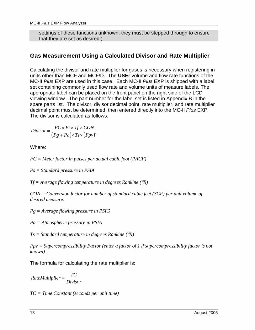
Gas Measurement Using a Calculated Divisor and Rate Multiplier Calculating the divisor and rate multiplier for gases is necessary when registering in units other than MCF and MCF/D. The USEr volume and flow rate functions of the MC-II Plus EXP are used in this case. Each MC-II Plus EXP is shipped with a label set containing commonly used flow rate and volume units of measure labels. The appropriate label can be placed on the front panel on the right side of the LCD viewing window. The part number for the label set is listed in Appendix B in the spare parts list. The divisor, divisor decimal point, rate multiplier, and rate multiplier decimal point must be determined, then entered directly into the MC-II Plus EXP. The divisor is calculated as follows:
( ) ( )2FpvTsPaPgCONTfPsFCDivisor
××+×××
=
Where: FC = Meter factor in pulses per actual cubic foot (PACF) Ps = Standard pressure in PSIA Tf = Average flowing temperature in degrees Rankine (°R) CON = Conversion factor for number of standard cubic feet (SCF) per unit volume of desired measure. Pg = Average flowing pressure in PSIG Pa = Atmospheric pressure in PSIA Ts = Standard temperature in degrees Rankine (°R) Fpv = Supercompressibility Factor (enter a factor of 1 if supercompressibility factor is not known) The formula for calculating the rate multiplier is:
DivisorTClierRateMultip =
TC = Time Constant (seconds per unit time)
MC-II Plus EXP Flow Analyzer
August 2005 19
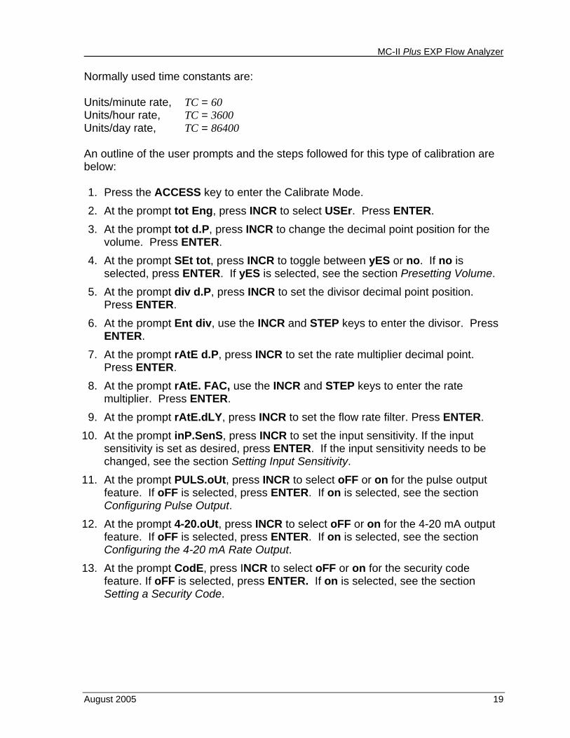
Normally used time constants are: Units/minute rate, TC = 60 Units/hour rate, TC = 3600 Units/day rate, TC = 86400 An outline of the user prompts and the steps followed for this type of calibration are below: 1. Press the ACCESS key to enter the Calibrate Mode. 2. At the prompt tot Eng, press INCR to select USEr. Press ENTER. 3. At the prompt tot d.P, press INCR to change the decimal point position for the
volume. Press ENTER. 4. At the prompt SEt tot, press INCR to toggle between yES or no. If no is
selected, press ENTER. If yES is selected, see the section Presetting Volume. 5. At the prompt div d.P, press INCR to set the divisor decimal point position.
Press ENTER. 6. At the prompt Ent div, use the INCR and STEP keys to enter the divisor. Press
ENTER. 7. At the prompt rAtE d.P, press INCR to set the rate multiplier decimal point.
Press ENTER. 8. At the prompt rAtE. FAC, use the INCR and STEP keys to enter the rate
multiplier. Press ENTER. 9. At the prompt rAtE.dLY, press INCR to set the flow rate filter. Press ENTER.
10. At the prompt inP.SenS, press INCR to set the input sensitivity. If the input sensitivity is set as desired, press ENTER. If the input sensitivity needs to be changed, see the section Setting Input Sensitivity.
11. At the prompt PULS.oUt, press INCR to select oFF or on for the pulse output feature. If oFF is selected, press ENTER. If on is selected, see the section Configuring Pulse Output.
12. At the prompt 4-20.oUt, press INCR to select oFF or on for the 4-20 mA output feature. If oFF is selected, press ENTER. If on is selected, see the section Configuring the 4-20 mA Rate Output.
13. At the prompt CodE, press INCR to select oFF or on for the security code feature. If oFF is selected, press ENTER. If on is selected, see the section Setting a Security Code.
MC-II Plus EXP Flow Analyzer
20 August 2005
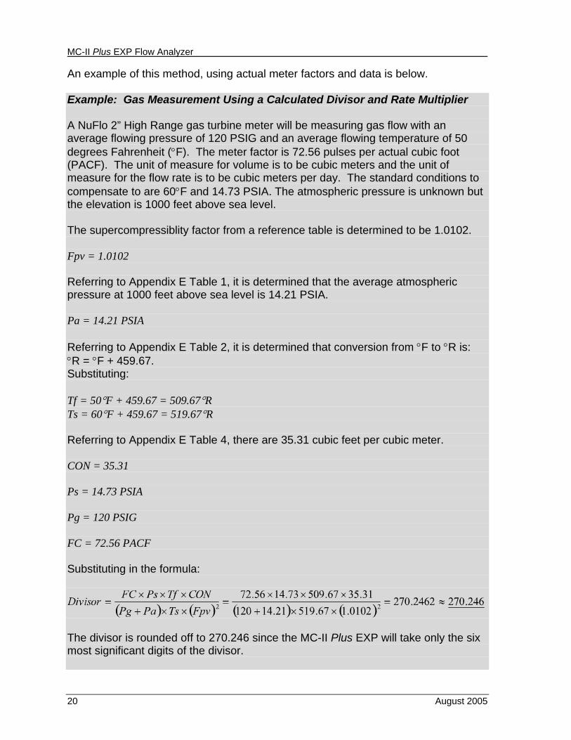
An example of this method, using actual meter factors and data is below. Example: Gas Measurement Using a Calculated Divisor and Rate Multiplier A NuFlo 2” High Range gas turbine meter will be measuring gas flow with an average flowing pressure of 120 PSIG and an average flowing temperature of 50 degrees Fahrenheit (°F). The meter factor is 72.56 pulses per actual cubic foot (PACF). The unit of measure for volume is to be cubic meters and the unit of measure for the flow rate is to be cubic meters per day. The standard conditions to compensate to are 60°F and 14.73 PSIA. The atmospheric pressure is unknown but the elevation is 1000 feet above sea level. The supercompressiblity factor from a reference table is determined to be 1.0102. Fpv = 1.0102 Referring to Appendix E Table 1, it is determined that the average atmospheric pressure at 1000 feet above sea level is 14.21 PSIA. Pa = 14.21 PSIA Referring to Appendix E Table 2, it is determined that conversion from °F to °R is: °R = °F + 459.67. Substituting: Tf = 50°F + 459.67 = 509.67°R Ts = 60°F + 459.67 = 519.67°R Referring to Appendix E Table 4, there are 35.31 cubic feet per cubic meter. CON = 35.31 Ps = 14.73 PSIA Pg = 120 PSIG FC = 72.56 PACF Substituting in the formula:
The divisor is rounded off to 270.246 since the MC-II Plus EXP will take only the six most significant digits of the divisor.
MC-II Plus EXP Flow Analyzer
August 2005 21
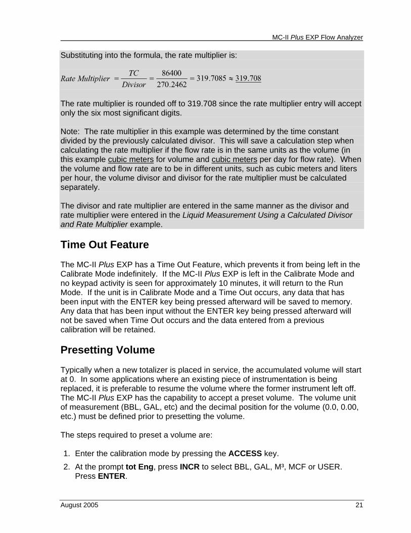
Substituting into the formula, the rate multiplier is:
The rate multiplier is rounded off to 319.708 since the rate multiplier entry will accept only the six most significant digits. Note: The rate multiplier in this example was determined by the time constant divided by the previously calculated divisor. This will save a calculation step when calculating the rate multiplier if the flow rate is in the same units as the volume (in this example cubic meters for volume and cubic meters per day for flow rate). When the volume and flow rate are to be in different units, such as cubic meters and liters per hour, the volume divisor and divisor for the rate multiplier must be calculated separately. The divisor and rate multiplier are entered in the same manner as the divisor and rate multiplier were entered in the Liquid Measurement Using a Calculated Divisor and Rate Multiplier example. Time Out Feature The MC-II Plus EXP has a Time Out Feature, which prevents it from being left in the Calibrate Mode indefinitely. If the MC-II Plus EXP is left in the Calibrate Mode and no keypad activity is seen for approximately 10 minutes, it will return to the Run Mode. If the unit is in Calibrate Mode and a Time Out occurs, any data that has been input with the ENTER key being pressed afterward will be saved to memory. Any data that has been input without the ENTER key being pressed afterward will not be saved when Time Out occurs and the data entered from a previous calibration will be retained. Presetting Volume Typically when a new totalizer is placed in service, the accumulated volume will start at 0. In some applications where an existing piece of instrumentation is being replaced, it is preferable to resume the volume where the former instrument left off. The MC-II Plus EXP has the capability to accept a preset volume. The volume unit of measurement (BBL, GAL, etc) and the decimal position for the volume (0.0, 0.00, etc.) must be defined prior to presetting the volume. The steps required to preset a volume are: 1. Enter the calibration mode by pressing the ACCESS key. 2. At the prompt tot Eng, press INCR to select BBL, GAL, M³, MCF or USER.
Press ENTER.
MC-II Plus EXP Flow Analyzer
22 August 2005
3. At the prompt tot d.P, press INCR to change the decimal point position for the volume. Press ENTER.
4. At the prompt SEt tot, press INCR to toggle between yES or no until yES is selected. Press ENTER.
5. At the prompt SEt.tot, use INCR and STEP to change the volume. The currently selected volumetric unit of measure will be displayed and the current decimal point will be indicated. Press ENTER.
6. At this point, the volume has been preset. Pressing ACCESS exits the Calibrate Mode without making any further changes, or the remaining steps may be implemented.
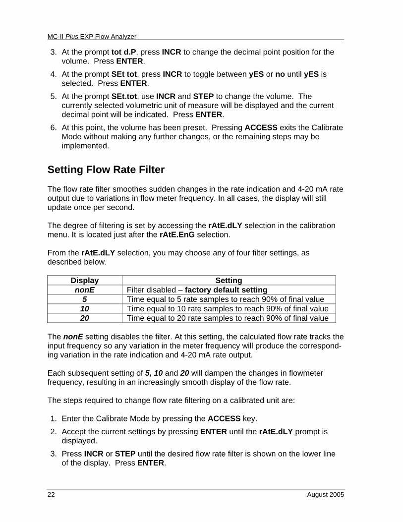
Setting Flow Rate Filter The flow rate filter smoothes sudden changes in the rate indication and 4-20 mA rate output due to variations in flow meter frequency. In all cases, the display will still update once per second. The degree of filtering is set by accessing the rAtE.dLY selection in the calibration menu. It is located just after the rAtE.EnG selection. From the rAtE.dLY selection, you may choose any of four filter settings, as described below.
Display Setting nonE Filter disabled – factory default setting
5 Time equal to 5 rate samples to reach 90% of final value 10 Time equal to 10 rate samples to reach 90% of final value 20 Time equal to 20 rate samples to reach 90% of final value
The nonE setting disables the filter. At this setting, the calculated flow rate tracks the input frequency so any variation in the meter frequency will produce the correspond-ing variation in the rate indication and 4-20 mA rate output. Each subsequent setting of 5, 10 and 20 will dampen the changes in flowmeter frequency, resulting in an increasingly smooth display of the flow rate. The steps required to change flow rate filtering on a calibrated unit are: 1. Enter the Calibrate Mode by pressing the ACCESS key. 2. Accept the current settings by pressing ENTER until the rAtE.dLY prompt is
displayed. 3. Press INCR or STEP until the desired flow rate filter is shown on the lower line
of the display. Press ENTER.
MC-II Plus EXP Flow Analyzer
August 2005 23
4. At this point, the flow rate filtering has been configured. Pressing ACCESS exits the Calibrate Mode without making any further changes, or the remaining steps may be implemented.
Setting Input Sensitivity The input sensitivity of the MC-II Plus EXP is measured in millivolts (mV) peak-to-peak. This is the threshold value at which the circuitry responds to a signal. If the input signal is below this value, the MC-II Plus EXP will not count the electrical pulses as a valid turbine meter signal. If the input signal is equal to or above this value, the electrical pulses received at the input will be counted. Care must be taken to ensure that the input sensitivity is high enough to reject any electrical noise on the signal line but not too high to miss pulses from the flow meter. The input sensitivity of the MC-II Plus EXP may be set to 6 different input sensitivities: 20 mV, 40 mV, 60 mV, 80 mV, 100 mV and 120 mV. The factory default is 20 mV. The steps required to change the input sensitivity on a calibrated unit are: 1. Enter the Calibrate Mode by pressing the ACCESS key. 2. Accept the current settings by pressing ENTER until the inP.SEnS prompt is
displayed. 3. Press INCR until the desired sensitivity is shown on the lower line of the display.
Press ENTER. 4. At this point, the input sensitivity has been configured. Pressing ACCESS exits
the Calibrate Mode without making any further changes, or the remaining steps may be implemented.
MC-II Plus EXP Flow Analyzer
24 August 2005
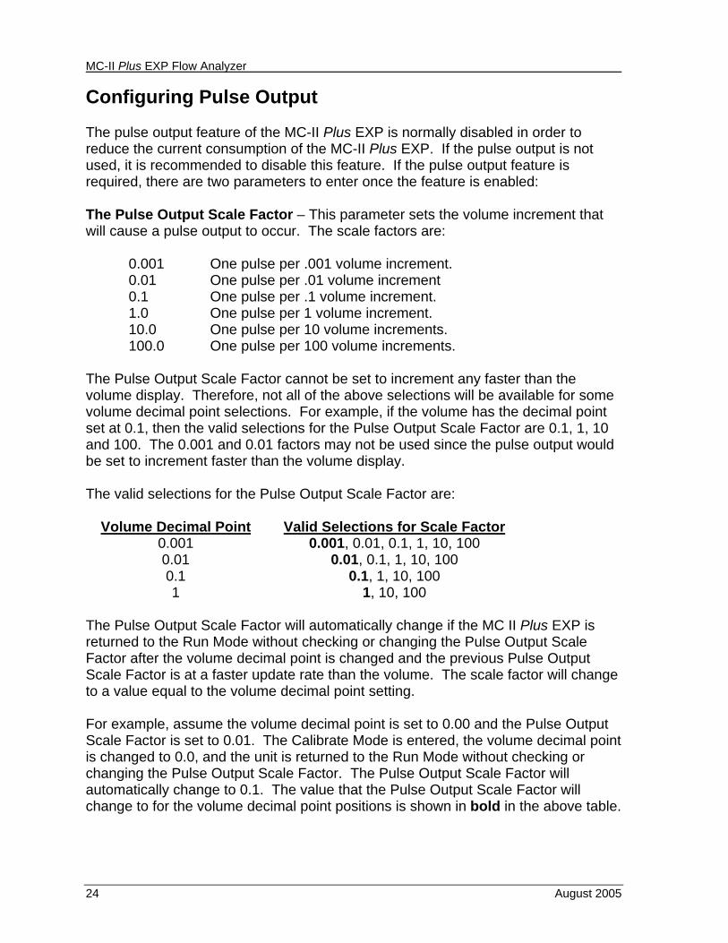
Configuring Pulse Output The pulse output feature of the MC-II Plus EXP is normally disabled in order to reduce the current consumption of the MC-II Plus EXP. If the pulse output is not used, it is recommended to disable this feature. If the pulse output feature is required, there are two parameters to enter once the feature is enabled: The Pulse Output Scale Factor – This parameter sets the volume increment that will cause a pulse output to occur. The scale factors are:
0.001 One pulse per .001 volume increment. 0.01 One pulse per .01 volume increment 0.1 One pulse per .1 volume increment. 1.0 One pulse per 1 volume increment. 10.0 One pulse per 10 volume increments. 100.0 One pulse per 100 volume increments.
The Pulse Output Scale Factor cannot be set to increment any faster than the volume display. Therefore, not all of the above selections will be available for some volume decimal point selections. For example, if the volume has the decimal point set at 0.1, then the valid selections for the Pulse Output Scale Factor are 0.1, 1, 10 and 100. The 0.001 and 0.01 factors may not be used since the pulse output would be set to increment faster than the volume display. The valid selections for the Pulse Output Scale Factor are:
Volume Decimal Point Valid Selections for Scale Factor 0.001 0.001, 0.01, 0.1, 1, 10, 100 0.01 0.01, 0.1, 1, 10, 100 0.1 0.1, 1, 10, 100 1 1, 10, 100
The Pulse Output Scale Factor will automatically change if the MC II Plus EXP is returned to the Run Mode without checking or changing the Pulse Output Scale Factor after the volume decimal point is changed and the previous Pulse Output Scale Factor is at a faster update rate than the volume. The scale factor will change to a value equal to the volume decimal point setting. For example, assume the volume decimal point is set to 0.00 and the Pulse Output Scale Factor is set to 0.01. The Calibrate Mode is entered, the volume decimal point is changed to 0.0, and the unit is returned to the Run Mode without checking or changing the Pulse Output Scale Factor. The Pulse Output Scale Factor will automatically change to 0.1. The value that the Pulse Output Scale Factor will change to for the volume decimal point positions is shown in bold in the above table.
MC-II Plus EXP Flow Analyzer
August 2005 25
The Pulse Length Duration (Pulse Width) – This factor determines the length of each output pulse in milliseconds (ms). There are six user-selectable pulse lengths: 65 ms, 130 ms, 195 ms, 260 ms, 520 ms, and 1040 ms. The steps required to configure the pulse output are:
1. Enter the Calibrate Mode by pressing the ACCESS key. 2. Accept the current settings by pressing ENTER until the PULS.oUt prompt
appears. 3. Press INCR to toggle the bottom line to on in order to enable the feature. If the
output is not used, press INCR until oFF is displayed on the bottom line. Press ENTER.
4. At the PULS.div prompt, press INCR to change the Pulse Output Scale Factor. Press ENTER when the desired setting is displayed.
5. At the PULS.Lng prompt, press INCR to change the Pulse Length Duration. Press ENTER when the desired setting is displayed.
6. At this point, the pulse output has been configured. Pressing ACCESS exits the Calibrate Mode without making any further changes, or the remaining steps may be implemented.
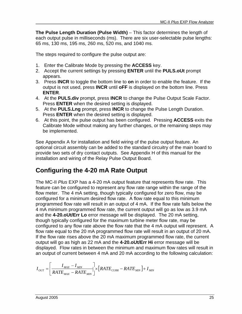
See Appendix A for installation and field wiring of the pulse output feature. An optional circuit assembly can be added to the standard circuitry of the main board to provide two sets of dry contact outputs. See Appendix H of this manual for the installation and wiring of the Relay Pulse Output Board. Configuring the 4-20 mA Rate Output The MC-II Plus EXP has a 4-20 mA output feature that represents flow rate. This feature can be configured to represent any flow rate range within the range of the flow meter. The 4 mA setting, though typically configured for zero flow, may be configured for a minimum desired flow rate. A flow rate equal to this minimum programmed flow rate will result in an output of 4 mA. If the flow rate falls below the 4 mA minimum programmed flow rate, the current output will go as low as 3.9 mA and the 4-20.oUt/Err Lo error message will be displayed. The 20 mA setting, though typically configured for the maximum turbine meter flow rate, may be configured to any flow rate above the flow rate that the 4 mA output will represent. A flow rate equal to the 20 mA programmed flow rate will result in an output of 20 mA. If the flow rate rises above the 20 mA maximum programmed flow rate, the current output will go as high as 22 mA and the 4-20.oUt/Err Hi error message will be displayed. Flow rates in between the minimum and maximum flow rates will result in an output of current between 4 mA and 20 mA according to the following calculation:
[ ] MINMINCURRMINMAX
MINMAXOUT IRATERATE
RATERATEIII +−×⎥
⎦
⎤⎢⎣
⎡−−
=
MC-II Plus EXP Flow Analyzer
26 August 2005
Where:
=OUTI The output current
=MAXI The maximum current output which is 20 mA
=MINI The minimum current output which is 4 mA
=MAXRATE The maximum programmed flow rate
=MINRATE The minimum programmed flow rate
=CURRRATE The flow rate Not only are the minimum and maximum flow rates programmed into the MC-II Plus EXP, but the 4 mA and 20 mA outputs are keypad adjustable for hardware calibration of the system insuring maximum output accuracy. CAUTION! – Before performing any 4-20 mA calibration, ensure that all peripheral equipment connected to the 4-20 mA current loop is either disconnected or disabled. Calibrating and testing the 4-20 mA output feature on the MC-II Plus EXP with the peripheral equipment in operation may cause false alarms or erroneous operation of the peripheral device or associated equipment. This is due to the fact that during calibration, the MC-II Plus EXP outputs a value close to 4.000 mA to calibrate the zero point and a value close to 20.000 mA to calibrate the full scale. The steps required to configure the 4-20 mA output are: 1. Enter the Calibrate Mode by pressing the ACCESS key. 2. Accept the current settings by pressing ENTER until the 4-20.oUt prompt
appears. 3. Press INCR to toggle the bottom line to on in order to enable the feature. If the
output is not used, press INCR until oFF is displayed on the bottom line. Press ENTER.
4. At the Lo A d.P prompt, press INCR to change the decimal point setting on the flow rate that is represented by 4 mA. The available selections are 0.0, 0.00, 0.000 and 0 (factory default is 0.0) with the current selection displayed on the lower line of the display. The current flow rate units are displayed. Press ENTER.
5. At the Lo A.Eng prompt, use the INCR and STEP keys to enter the flow rate that is represented by 4 mA. The currently selected flow rate units will be indicated. Press ENTER.
6. At the Hi A d.P prompt, press INCR to change the decimal point setting on the flow rate that is represented by 20 mA. The available selections are 0.0, 0.00,
MC-II Plus EXP Flow Analyzer
August 2005 27
0.000 and 0 (factory default is 0.0) with the current selection displayed on the lower line of the display. The currently selected flow rate units are displayed. Press ENTER.
7. At the Hi A.Eng prompt, use the INCR and STEP keys to enter the flow rate that is represented by 20 mA. The currently selected flow rate units will be indicated. Press ENTER.
8. For this step and the next step of the calibration, a milliamp meter has to be inserted in series with the 4-20 mA current loop and set to the highest resolution possible in the 4-20 mA range. At the CAL.A Lo prompt, use the INCR and STEP keys to enter the milliamp reading of the meter into the lower line of the display. The lower line of the display will show the previous low flow (4 mA) value (factory default 4.000). If hardware calibration is not required, the previous value can be accepted. In this event, the milliamp meter is not required. Press ENTER.
9. At the CAL.A Hi prompt, use the INCR and STEP keys to enter the milliamp reading of the meter into the lower line of the display. The lower line of the display will show the previous high flow (20 mA) value (factory default 20.000). If hardware calibration is not required, the previous value can be accepted. In this event, the milliamp meter is not required. Press ENTER.
10. At this point, the 4-20 mA output has been calibrated. Pressing ACCESS exits the Calibrate Mode without making any further changes, or the remaining steps may be implemented.
See Appendix A for installation and field wiring of the 4-20 mA feature. Setting a Security Code Setting a security code will prevent altering of calibration data or volume data by unauthorized personnel and is recommended to preserve data integrity of the system. Any 4-digit number may be selected for the security code. (It is recommended that 0000 not be selected as the security code since it is the default number displayed when the MC-II Plus EXP requests security code entry. If 0000 is set as the security code, simply pressing ENTER at this point will access the Calibrate Mode.) Select a number that will be easy to remember, but do not use a number that will be easy for unauthorized personnel to determine. 1. Enter the Calibrate Mode by pressing the ACCESS key. 2. Accept the current settings by pressing ENTER until the CodE prompt appears.
The lower line of the display will show oFF or on (factory default is oFF). Press INCR until on is displayed to enable the feature. Press ENTER.
3. At the Ent.CodE prompt, use INCR and STEP to enter a 4-digit security code. The lower line of the display will show the previously entered code (factory default code is 0000). Press ENTER to return to Run Mode.
MC-II Plus EXP Flow Analyzer
28 August 2005
Accessing an MC-II Plus EXP with a Security Code Accessing the Calibrate Mode of an MC-II Plus EXP with a security code requires knowledge of the security code. 1. Press the ACCESS key to enter the Calibrate Mode. 2. At the SEC.CodE prompt, use the INCR and STEP keys to enter the security
code. Press ENTER. If the correct security code is entered, the user will be granted calibration access. If the security code is incorrect, the device returns to Run Mode.
Appendix A MC-II Plus EXP Flow Analyzer
August 2005 A-1
Appendix A - Installation
General The MC-II Plus EXP is shipped assembled and ready to mount on top of a flow meter. The MC-II Plus EXP is shipped in the standard (typical) mounting configuration with ¾” pipe plugs installed facing right and left with the pipe union facing downward as shown on page A-6. An alternate mounting configuration with one ¾” pipe plug on the housing facing upward and another facing horizontally with the pipe union facing downward is shown on page A-7. To mount in the standard (typical) configuration follow the instructions in the section, Mounting on the Flow Meter in Appendix A. If the alternate mounting configuration is preferred, follow the instructions in the section Conversion to Alternate Mounting Configuration below.
Conversion to Alternate Mounting Configuration To gain access to the inside of the MC-II Plus EXP, rotate the cover of the enclosure counter-clockwise until it unscrews from the main body of the enclosure. Using a small standard blade screwdriver, remove the two #4-40 x 7/8” screws located to the right and left side of the display. Lift the display keypad assembly from the enclosure leaving the battery connected. Using a small standard blade screwdriver, remove the flow meter signal cable from terminal block TB2. Remove the meter signal cable from the pipe adapter/union assembly (refer to the illustration on page A-8 and Nomenclature drawing on page A-5). Remove the pipe plug from the side of the enclosure where the turbine meter is to be mounted. Remove the pipe adapter/union assembly from its current location and install it where the pipe plug was removed. Note: Do not use Teflon tape on threads of the union, adapter, or pipe plugs. Install the pipe plug where the pipe adapter/union assembly was removed. Remove the two phillips head baseplate mounting screws. Lift the baseplate/battery assembly from the enclosure. Replace the baseplate/battery assembly in the enclosure, positioning it with the shortest standoff next to the pipe union location so that the battery is perpendicular to the pipe union. Reinstall the two phillips head screws in the alternate holes in the baseplate. Reinstall the flow meter signal cable in the pipe adapter/union assembly with the wire ends extending into the enclosure. Reconnect the flow meter wiring to terminal block TB2. Mount the display keypad assembly to the enclosure with the two #4-40 x 7/8” screws. Recalibrate the MC-II Plus EXP (if necessary) then replace the enclosure cover. Note: If any input/output features are to be installed to the MC-II Plus EXP, do not replace the enclosure cover until mounting to the flow meter is complete and all wiring is installed.
MC-II Plus EXP Flow Analyzer Appendix A
A-2 August 2005
Mounting on the Flow Meter Install the flow meter into the flow line according to Flow Meter Instruction Manual, p.n. 100062201, supplied with the turbine meter. Lightly grease the threads on both ends of the magnetic pickup taking care to keep grease off of the connector contacts. Install the magnetic pickup as instructed the Flow Meter Instruction Manual. Position the MC-II Plus EXP above the flow meter pickup adapter. Plug the connector of the MC-II Plus EXP cable into the magnetic pickup and hand tighten the knurled nut on the connector. Mount the MC-II Plus EXP on the flow meter pickup adapter with the display facing the desired direction, tightening all sections of the pipe union. Note: Do not use Teflon tape on threads of the union, adapter, or pipe plugs.
Input / Output Features Caution: If the MC-II Plus EXP is installed in a hazardous location, all field wiring must conform to wiring methods for explosion proof installations as defined in the National Electric Code for installations within the United States or as specified in the Canadian Electric Code for installations within Canada. State and local wiring ordinances may also apply. There are five input/output features available for the MC-II Plus EXP. Each feature is covered individually in the following sections with wiring diagrams.
Pulse Output The Pulse Output is provided in the form of an optically isolated open collector transistor circuit. It can be used in conjunction with any other feature on the MC-II Plus EXP. A two-conductor cable from the MC-II Plus EXP to the remote location is required with a 5 to 30VDC power supply and suitable device for reading the open collector pulse output of the MC-II Plus EXP. The maximum current rating of the pulse output circuit is 40mA @ 30VDC. The Pulse Output Wiring Diagram is located on page A-10. The section in the manual, Configuring the Pulse Output, provides information regarding the setup of the pulse output feature.
An optional circuit assembly can be added to the standard circuitry of the main board to provide two sets of dry contact outputs. See Appendix H of this manual for the installation and wiring of the Relay Pulse Output Board.
Appendix A MC-II Plus EXP Flow Analyzer
August 2005 A-3
External Power Supply The External Power Supply feature is provided to allow the MC-II Plus EXP to be powered by an external power source, therefore extending the life of the internal lithium battery. The internal lithium battery provides a power supply backup in the event that the external power source fails. This allows the MC-II Plus EXP to retain calibration data and continue operation during a power failure. The MC-II Plus EXP is connected to the remote power supply by a two-conductor cable. The power supply and cable must be capable of supplying between 8 and 30 VDC @ 10mA. The External Power Supply wiring diagram is located on page A-11. This capability is available only if the 4-20 mA Rate Output is not used. Caution must also be taken when using the Amp & Square Output with the External Power Supply since both share a common negative (-) connection. The power supplies for both features must share a common negative (-) terminal or be totally isolated from each other.
4 to 20mA Rate Output The 4-20mA Rate Output provides a linear current output that represents flow rate. This output requires a two-conductor cable connected to an 8 to 30 VDC power supply (voltage required is dependent on loop resistance) and a current readout device located in the remote location. The 4-20 mA Rate Output current loop also powers the MC-II Plus EXP, therefore extending the life of the internal lithium battery. The internal lithium battery provides a power supply backup to retain calibration data and to continue accumulating volume in the event that the 4-20 mA current loop fails. The 4 to 20 mA Rate Output wiring diagram is located on page A-12. The section in the manual, Configuring the 4-20 mA Rate Output, provides information regarding the setup of the 4-20 mA output feature. The 4-20mA Rate Output and the Flow Meter Frequency Output circuits are not isolated from each other. If both outputs are required, verify that the power supplies and readout devices associated with each output are completely isolated from each other.
Flow Meter Frequency Output The Flow Meter Frequency Output (formerly called Amp & Square Output) provides an open drain transistor output at the turbine meter frequency, which may be used to provide flow rate and/or total information to peripheral equipment. The output requires a two-conductor cable from the MC-II Plus EXP to the remote frequency
MC-II Plus EXP Flow Analyzer Appendix A
A-4 August 2005
readout device requiring 50 mA or less and a 5 to 30 VDC power supply. The Amp & Square Output wiring diagram is located on page A-13. The Flow Meter Frequency Output and 4-20 mA Rate Output are not isolated from each other. If both outputs are required, verify that the power supplies and readout devices associated with each output are completely isolated from each other. Caution must also be taken when using the Flow Meter Frequency Output while powering the device from an external power supply since both share a common negative (-) connection. The power supplies must share a common negative (-) terminal or be totally isolated from each other. The Flow Meter Frequency Output terminals on the MC-II Plus EXP circuit assembly are labeled A & S Out representing Amp & Square Output.
Remote Reset Input The Remote Reset Input allows the operator to reset the accumulated volume on the MC-II Plus EXP to zero without opening the enclosure. This input is optically isolated and bi-polar. It may be connected in a sink or source mode. The input is shown connected in two ways, with a power supply and switch in a remote location and with an explosion proof switch at the instrument. The Remote Reset Input wiring diagrams are located on pages A-14 and A-15.
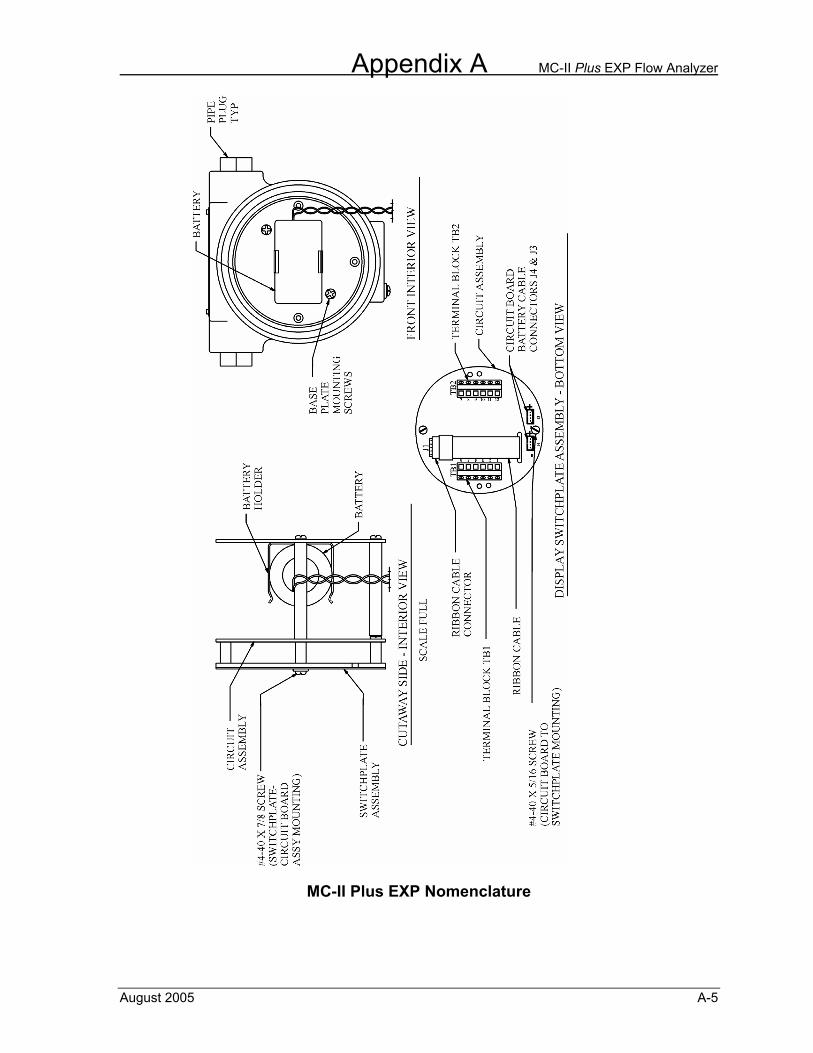
Appendix A MC-II Plus EXP Flow Analyzer
August 2005 A-5
MC-II Plus EXP Nomenclature
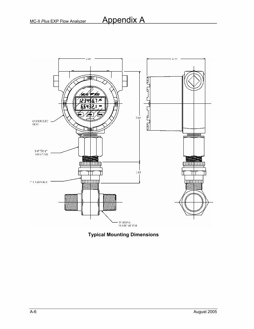
MC-II Plus EXP Flow Analyzer Appendix A
A-6 August 2005
Typical Mounting Dimensions
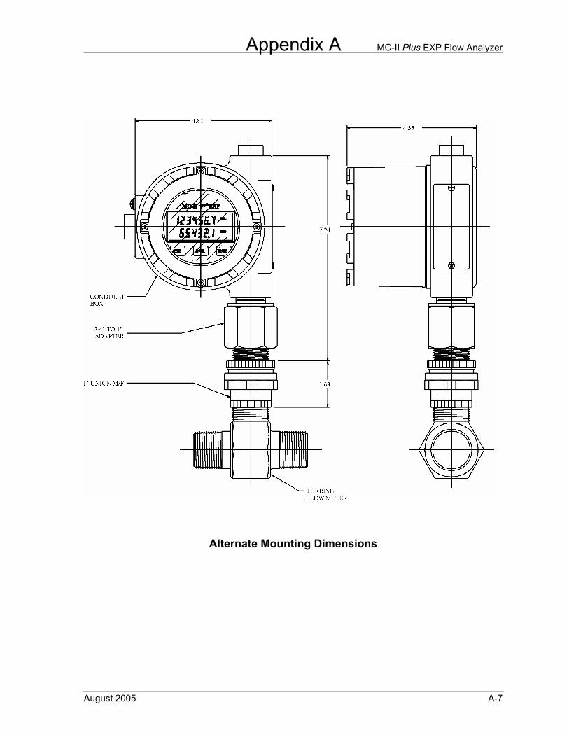
Appendix A MC-II Plus EXP Flow Analyzer
August 2005 A-7
Alternate Mounting Dimensions
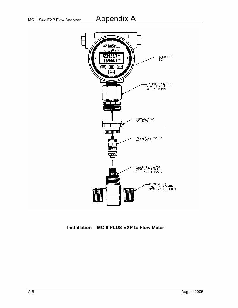
MC-II Plus EXP Flow Analyzer Appendix A
A-8 August 2005
Installation – MC-II PLUS EXP to Flow Meter
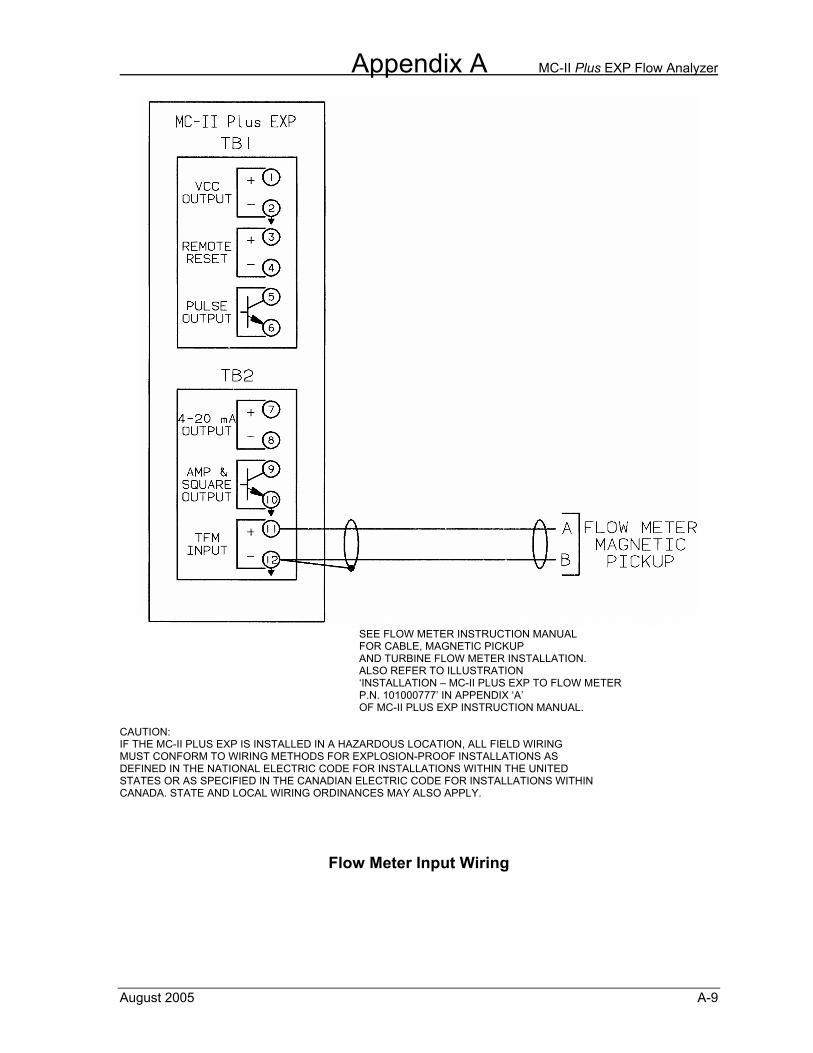
Appendix A MC-II Plus EXP Flow Analyzer
August 2005 A-9
SEE FLOW METER INSTRUCTION MANUAL FOR CABLE, MAGNETIC PICKUP AND TURBINE FLOW METER INSTALLATION.
ALSO REFER TO ILLUSTRATION ‘INSTALLATION – MC-II PLUS EXP TO FLOW METER P.N. 101000777’ IN APPENDIX ‘A’ OF MC-II PLUS EXP INSTRUCTION MANUAL. CAUTION: IF THE MC-II PLUS EXP IS INSTALLED IN A HAZARDOUS LOCATION, ALL FIELD WIRING MUST CONFORM TO WIRING METHODS FOR EXPLOSION-PROOF INSTALLATIONS AS DEFINED IN THE NATIONAL ELECTRIC CODE FOR INSTALLATIONS WITHIN THE UNITED STATES OR AS SPECIFIED IN THE CANADIAN ELECTRIC CODE FOR INSTALLATIONS WITHIN CANADA. STATE AND LOCAL WIRING ORDINANCES MAY ALSO APPLY.
Flow Meter Input Wiring
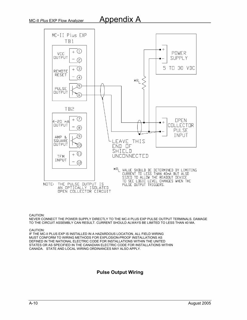
MC-II Plus EXP Flow Analyzer Appendix A
A-10 August 2005
CAUTION: NEVER CONNECT THE POWER SUPPLY DIRECTLY TO THE MC-II PLUS EXP PULSE OUTPUT TERMINALS. DAMAGE TO THE CIRCUIT ASSEMBLY CAN RESULT. CURRENT SHOULD ALWAYS BE LIMITED TO LESS THAN 40 MA. CAUTION: IF THE MC-II PLUS EXP IS INSTALLED IN A HAZARDOUS LOCATION, ALL FIELD WIRING MUST CONFORM TO WIRING METHODS FOR EXPLOSION-PROOF INSTALLATIONS AS DEFINED IN THE NATIONAL ELECTRIC CODE FOR INSTALLATIONS WITHIN THE UNITED STATES OR AS SPECIFIED IN THE CANADIAN ELECTRIC CODE FOR INSTALLATIONS WITHIN CANADA. STATE AND LOCAL WIRING ORDINANCES MAY ALSO APPLY.
Pulse Output Wiring
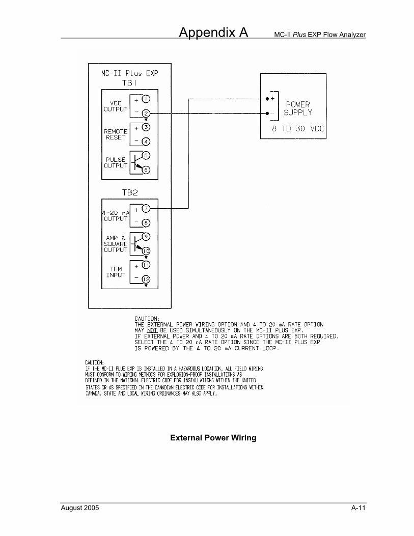
Appendix A MC-II Plus EXP Flow Analyzer
August 2005 A-11
External Power Wiring
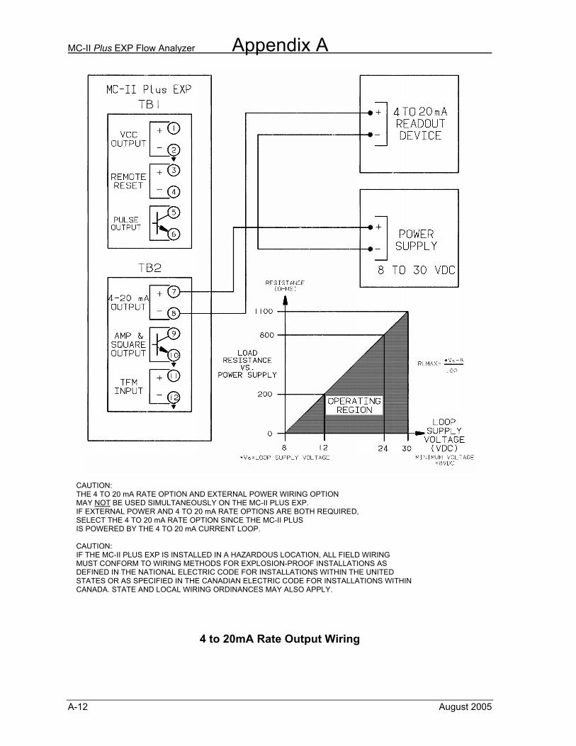
MC-II Plus EXP Flow Analyzer Appendix A
A-12 August 2005
CAUTION: THE 4 TO 20 mA RATE OPTION AND EXTERNAL POWER WIRING OPTION MAY NOT BE USED SIMULTANEOUSLY ON THE MC-II PLUS EXP. IF EXTERNAL POWER AND 4 TO 20 mA RATE OPTIONS ARE BOTH REQUIRED, SELECT THE 4 TO 20 mA RATE OPTION SINCE THE MC-II PLUS IS POWERED BY THE 4 TO 20 mA CURRENT LOOP. CAUTION: IF THE MC-II PLUS EXP IS INSTALLED IN A HAZARDOUS LOCATION, ALL FIELD WIRING MUST CONFORM TO WIRING METHODS FOR EXPLOSION-PROOF INSTALLATIONS AS DEFINED IN THE NATIONAL ELECTRIC CODE FOR INSTALLATIONS WITHIN THE UNITED STATES OR AS SPECIFIED IN THE CANADIAN ELECTRIC CODE FOR INSTALLATIONS WITHIN CANADA. STATE AND LOCAL WIRING ORDINANCES MAY ALSO APPLY.
4 to 20mA Rate Output Wiring
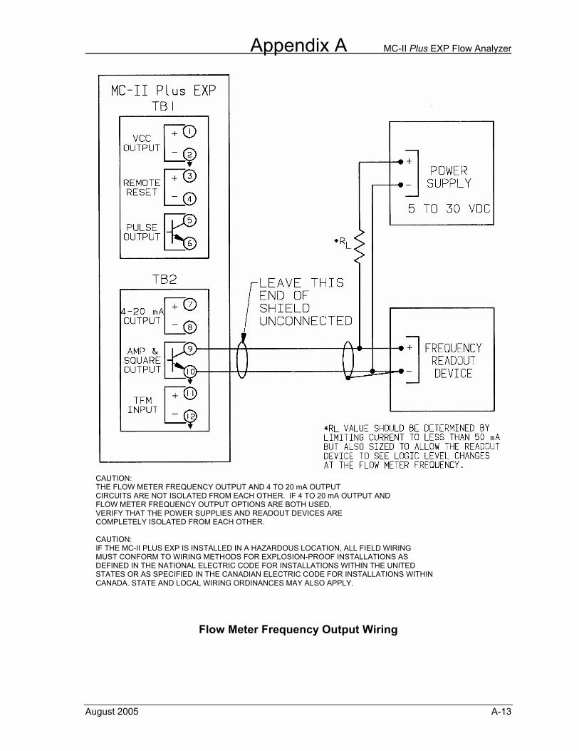
Appendix A MC-II Plus EXP Flow Analyzer
August 2005 A-13
CAUTION: THE FLOW METER FREQUENCY OUTPUT AND 4 TO 20 mA OUTPUT CIRCUITS ARE NOT ISOLATED FROM EACH OTHER. IF 4 TO 20 mA OUTPUT AND FLOW METER FREQUENCY OUTPUT OPTIONS ARE BOTH USED, VERIFY THAT THE POWER SUPPLIES AND READOUT DEVICES ARE COMPLETELY ISOLATED FROM EACH OTHER. CAUTION: IF THE MC-II PLUS EXP IS INSTALLED IN A HAZARDOUS LOCATION, ALL FIELD WIRING MUST CONFORM TO WIRING METHODS FOR EXPLOSION-PROOF INSTALLATIONS AS DEFINED IN THE NATIONAL ELECTRIC CODE FOR INSTALLATIONS WITHIN THE UNITED STATES OR AS SPECIFIED IN THE CANADIAN ELECTRIC CODE FOR INSTALLATIONS WITHIN CANADA. STATE AND LOCAL WIRING ORDINANCES MAY ALSO APPLY.
Flow Meter Frequency Output Wiring
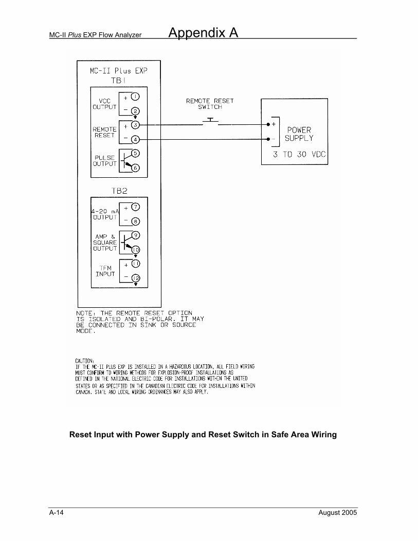
MC-II Plus EXP Flow Analyzer Appendix A
A-14 August 2005
Reset Input with Power Supply and Reset Switch in Safe Area Wiring
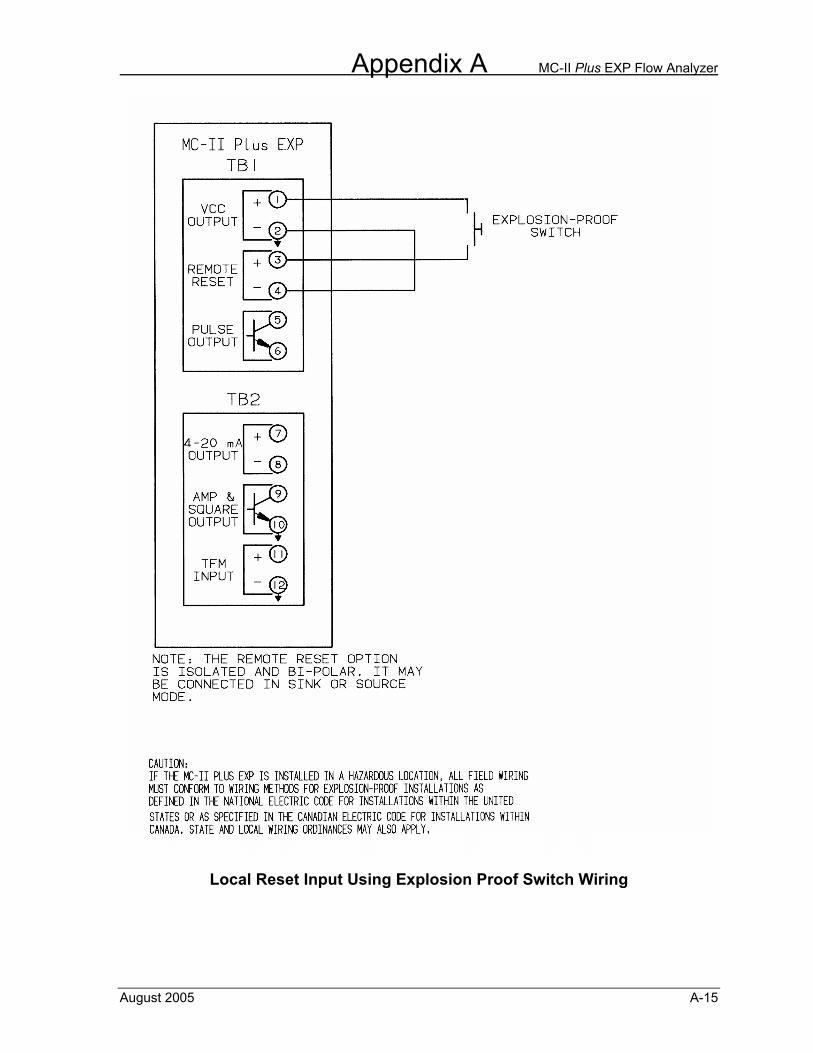
Appendix A MC-II Plus EXP Flow Analyzer
August 2005 A-15
Local Reset Input Using Explosion Proof Switch Wiring

MC-II Plus EXP Flow Analyzer Appendix A
A-16 August 2005
Appendix B MC-II Plus EXP Flow Analyzer
August 2005 B-1
Appendix B - MC-II Plus EXP Maintenance
The MC-II Plus EXP is designed to provide many years of service with minimal maintenance. Typical maintenance of the MC-II Plus EXP is periodic replacement of the lithium battery, which is designed to last two or more years in normal service. Other maintenance of the MC-II Plus EXP covered in this section is circuit assembly or keypad assembly replacement.
Warning! Under normal conditions the MC-II Plus EXP poses no hazard when opened in a safe area. Do not open the enclosure in an area classified as a hazardous area. Caution The lithium battery, which powers the MC-II Plus EXP is a sealed unit; but if one of these batteries leaks, there is the possibility of toxic fumes being present when the enclosure is opened. Select a well-ventilated area in which to open the enclosure and avoid breathing fumes, which may be trapped inside the enclosure. Care must be taken in handling and disposing of a spent or damaged battery. See additional Lithium Battery Information in Appendix G of this manual.
Battery Replacement The MC-II Plus EXP uses a lithium battery with a life expectancy of approximately two years. Due to the flat discharge curve characteristics of the lithium battery, it is difficult to determine how much life remains in a battery. It is recommended that the battery be replaced at two-year intervals to preserve calibration and accumulated volume data. Caution There are two battery cable connectors on the lower portion of the circuit assembly labeled J3 and J4. The original battery cable will be connected to one of these connectors. When replacing the battery, plug the replacement battery cable into the unused connector before removing the used battery. Failure to connect the replacement battery before disconnecting the used battery will result in loss of accumulated volume and calibration data. To gain access to the inside of the MC-II Plus EXP, rotate the cover of the enclosure counter-clockwise until it unscrews from the main body of the enclosure. Using a small standard blade screwdriver, remove the two #4-40 x 7/8” screws located to the right and left side of the display. Lift the display/keypad assembly from the enclosure making sure the circuit assembly does not contact the enclosure. Remove the battery from the battery holder in the enclosure ensuring that the battery cable stays connected to the circuit assembly. Install the replacement battery in the battery holder in the same position as the original battery. Plug the replacement battery into the circuit assembly at J3 or J4.
MC-II Plus EXP Flow Analyzer Appendix B
B-2 August 2005
Disconnect the used battery from the circuit assembly. Place the circuit assembly over the standoffs and fasten with the two #4-40 x 7/8” screws insuring that all connector wiring is inside the enclosure and in no position where it may be damaged when the enclosure cover is replaced. Replace the enclosure cover by threading it onto the enclosure in a clockwise direction. Circuit Assembly Replacement If the circuit assembly being replaced is still fully or partially functional, record the volume reading and all calibration data before removing the circuit assembly. To gain access to the inside of the MC-II Plus EXP, rotate the cover of the enclosure counter-clockwise until it unscrews from the main body of the enclosure. Using a small standard blade screwdriver, remove the two #4-40 x 7/8” screws located to the right and left side of the display. Lift the display/keypad assembly from the enclosure. Write down the location of all cable connections to the circuit assembly. Remove all power from all peripheral circuits to the MC-II Plus EXP. If this is not possible, place insulating tape on all wiring leads when removing them from the terminal blocks. Using a small standard blade screwdriver, remove all wiring from terminal blocks TB1 and TB2 insuring that all wiring that is connected to powered circuits is insulated with tape, as described above, to prevent short circuits. Unplug the battery cable from the circuit assembly. Unplug the keypad ribbon cable from J1 on the circuit assembly. Remove the two #4-40 x 5/16” screws fastening the circuit assembly to the keypad assembly. Remove the original circuit assembly, allowing the keypad ribbon cable to slip through the slot in the circuit assembly. Insert the ribbon cable of the keypad through the slot in the replacement circuit assembly and plug it into J1. Mount the circuit assembly to the keypad with the two #4-40 x 5/16” screws. Reconnect the battery cable to J3 or J4 on the circuit assembly. Reconnect all wiring to terminal blocks TB1 and TB2. Mount the display/keypad assembly to the enclosure with the two #4-40 x 7/8” screws. Recalibrate the MC-II Plus EXP, then replace the enclosure cover. Re-establish power to the peripheral circuitry. Keypad Replacement To gain access to the inside of the MC-II Plus EXP, rotate the cover of the enclosure counter-clockwise until it unscrews from the main body of the enclosure. Using a small standard blade screwdriver, remove the two #4-40 x 7/8” screws located to the right and left side of the display. Lift the display/keypad assembly from the enclosure. Unplug the switchplate ribbon cable from J1 on the circuit assembly. Remove the two #4-40 x 5/16” screws fastening the circuit assembly to the switchplate. Remove the circuit assembly, allowing the switchplate ribbon cable to slip through the slot in the circuit assembly.
Appendix B MC-II Plus EXP Flow Analyzer
August 2005 B-3
Insert the ribbon cable of the replacement switchplate through the slot in the circuit assembly and connect it to J1. Mount the circuit assembly to the switchplate with the two #4-40 x 5/16” screws. Mount the display/keypad assembly to the enclosure with the two #4-40 x 7/8” screws. Recalibrate the MC-II Plus EXP if necessary and replace the enclosure cover.
Spare Parts List
Quantity Part Number Description
1 100079534 Switchplate Assembly 1 101001372 CPU Circuit Assembly 1 100080050 Cable Assembly – Flowmeter 1 101203194 Label Set 1 100005111 Battery – Lithium – 3.6V 1 100002605 Desiccant Packet 1 101209152 Relay Option Circuit Assembly 1 101209622 Relay Option Relay
EXPLOSION HAZARD – SUBSTITUTION OF COMPONENTS MAY IMPAIR SUITABILITY FOR CLASS I, DIV. 1 and CLASS II, DIV. 1 CERTIFICATION.
USE OF SPARE PARTS OTHER THAN THOSE IDENTIFIED BY NUFLO VOIDS CSA CERTIFICATION. NUFLO BEARS NO LEGAL RESPONSIBILITY FOR THE PERFORMANCE OF A PRODUCT THAT HAS BEEN SERVICED OR REPAIRED WITH PARTS THAT ARE NOT AUTHORIZED BY NUFLO.
!WARNING

MC-II Plus EXP Flow Analyzer Appendix B
B-4 August 2005
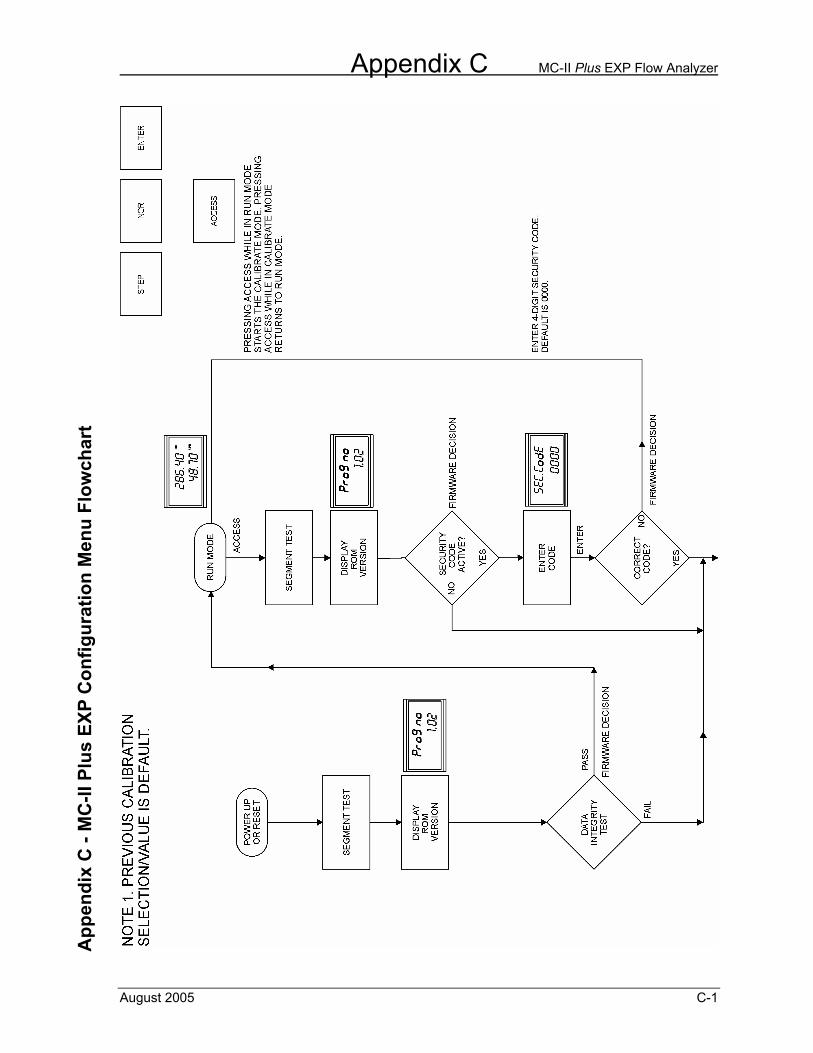
Appendix C MC-II Plus EXP Flow Analyzer
August 2005 C-1
App
endi
x C
- M
C-II
Plu
s EX
P C
onfig
urat
ion
Men
u Fl
owch
art
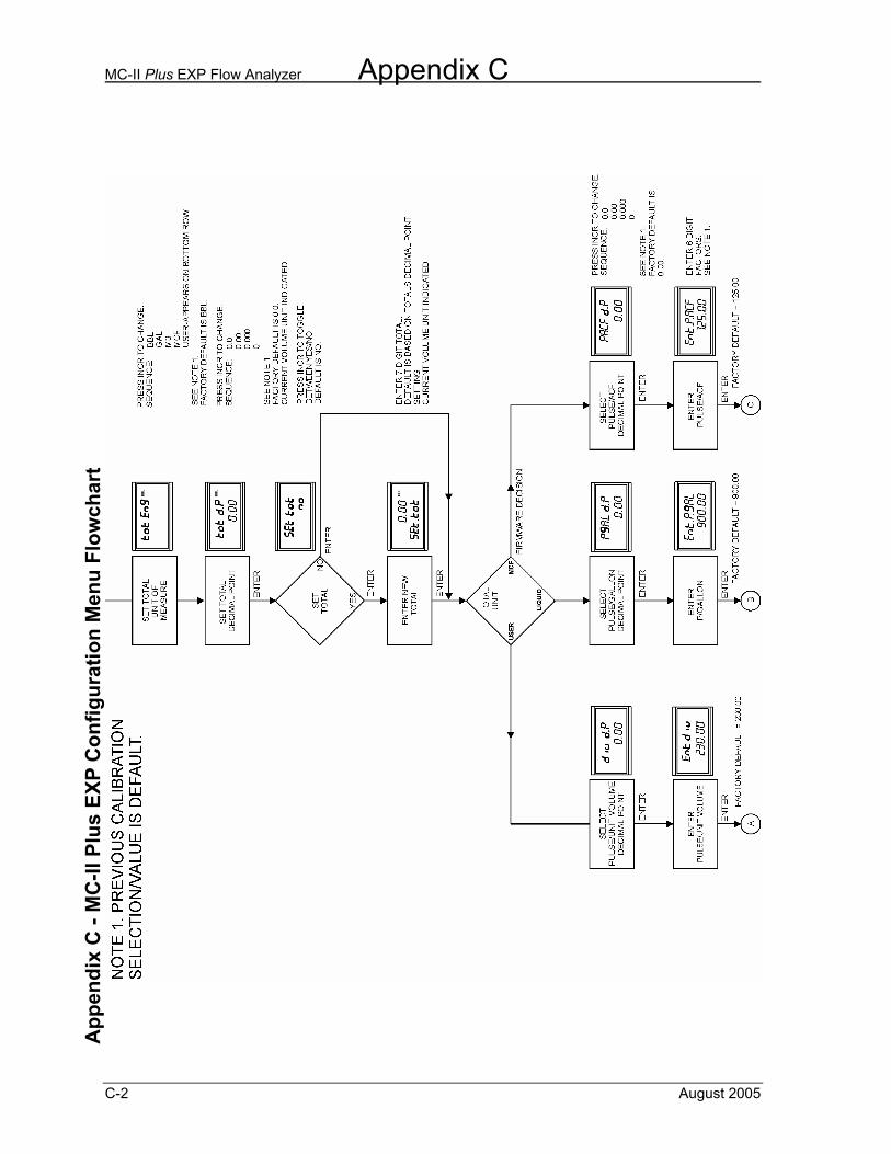
MC-II Plus EXP Flow Analyzer Appendix C
C-2 August 2005
App
endi
x C
- M
C-II
Plu
s EX
P C
onfig
urat
ion
Men
u Fl
owch
art
App
endi
x C
- M
C-II
Plu
s EX
P C
onfig
urat
ion
Men
u Fl
owch
art
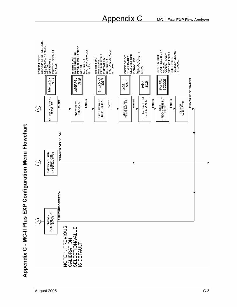
Appendix C MC-II Plus EXP Flow Analyzer
August 2005 C-3
App
endi
x C
- M
C-II
Plu
s EX
P C
onfig
urat
ion
Men
u Fl
owch
art
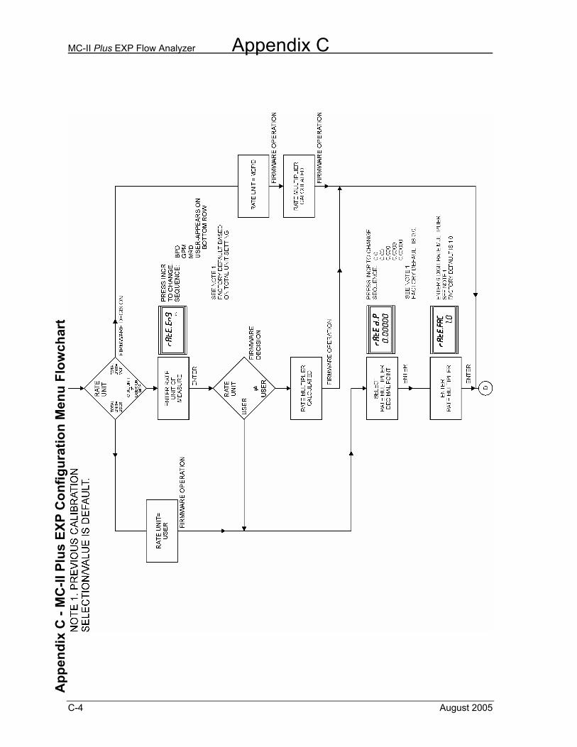
MC-II Plus EXP Flow Analyzer Appendix C
C-4 August 2005
A
ppen
dix
C -
MC
-II P
lus
EXP
Con
figur
atio
n M
enu
Flow
char
t
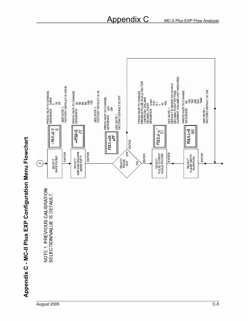
Appendix C MC-II Plus EXP Flow Analyzer
August 2005 C-5
App
endi
x C
- M
C-II
Plu
s EX
P C
onfig
urat
ion
Men
u Fl
owch
art
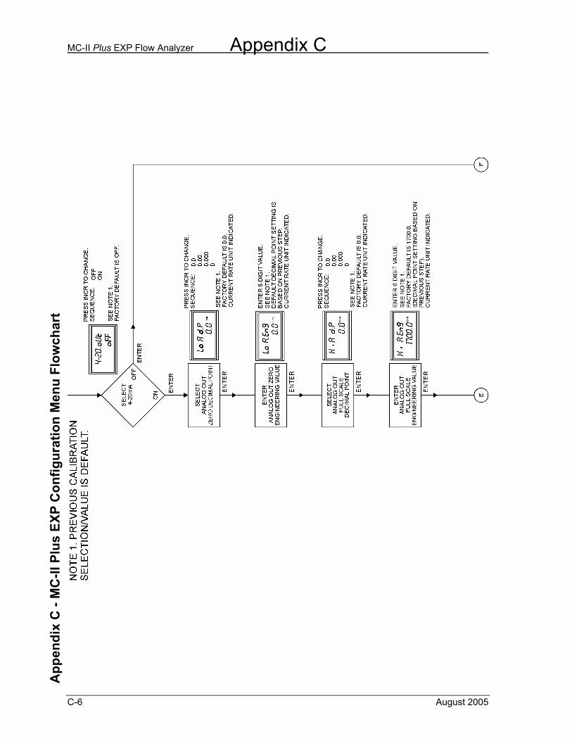
MC-II Plus EXP Flow Analyzer Appendix C
C-6 August 2005
App
endi
x C
- M
C-II
Plu
s EX
P C
onfig
urat
ion
Men
u Fl
owch
art
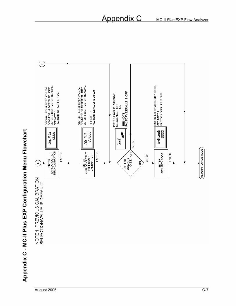
Appendix C MC-II Plus EXP Flow Analyzer
August 2005 C-7
A
ppen
dix
C -
MC
-II P
lus
EXP
Con
figur
atio
n M
enu
Flow
char
t

MC-II Plus EXP Flow Analyzer Appendix C
C-8 August 2005
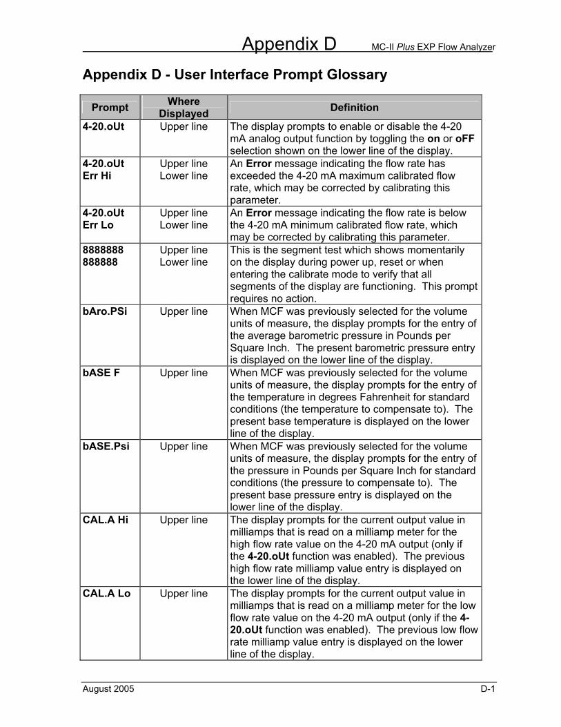
Appendix D MC-II Plus EXP Flow Analyzer
August 2005 D-1
Appendix D - User Interface Prompt Glossary
Prompt Where Displayed Definition
4-20.oUt Upper line The display prompts to enable or disable the 4-20 mA analog output function by toggling the on or oFF selection shown on the lower line of the display.
4-20.oUt Err Hi
Upper line Lower line
An Error message indicating the flow rate has exceeded the 4-20 mA maximum calibrated flow rate, which may be corrected by calibrating this parameter.
4-20.oUt Err Lo
Upper line Lower line
An Error message indicating the flow rate is below the 4-20 mA minimum calibrated flow rate, which may be corrected by calibrating this parameter.
8888888 888888
Upper line Lower line
This is the segment test which shows momentarily on the display during power up, reset or when entering the calibrate mode to verify that all segments of the display are functioning. This prompt requires no action.
bAro.PSi Upper line When MCF was previously selected for the volume units of measure, the display prompts for the entry of the average barometric pressure in Pounds per Square Inch. The present barometric pressure entry is displayed on the lower line of the display.
bASE F Upper line When MCF was previously selected for the volume units of measure, the display prompts for the entry of the temperature in degrees Fahrenheit for standard conditions (the temperature to compensate to). The present base temperature is displayed on the lower line of the display.
bASE.Psi Upper line When MCF was previously selected for the volume units of measure, the display prompts for the entry of the pressure in Pounds per Square Inch for standard conditions (the pressure to compensate to). The present base pressure entry is displayed on the lower line of the display.
CAL.A Hi Upper line The display prompts for the current output value in milliamps that is read on a milliamp meter for the high flow rate value on the 4-20 mA output (only if the 4-20.oUt function was enabled). The previous high flow rate milliamp value entry is displayed on the lower line of the display.
CAL.A Lo Upper line The display prompts for the current output value in milliamps that is read on a milliamp meter for the low flow rate value on the 4-20 mA output (only if the 4-20.oUt function was enabled). The previous low flow rate milliamp value entry is displayed on the lower line of the display.
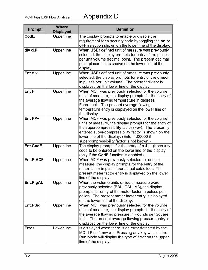
MC-II Plus EXP Flow Analyzer Appendix D
D-2 August 2005
Prompt Where Displayed Definition
CodE Upper line The display prompts to enable or disable the requirement for a security code by toggling the on or oFF selection shown on the lower line of the display.
div d.P Upper line When USEr defined unit of measure was previously selected, the display prompts for entry of the pulses per unit volume decimal point. The present decimal point placement is shown on the lower line of the display.
Ent div Upper line When USEr defined unit of measure was previously selected, the display prompts for entry of the divisor in pulses per unit volume. The present divisor is displayed on the lower line of the display.
Ent F Upper line When MCF was previously selected for the volume units of measure, the display prompts for the entry of the average flowing temperature in degrees Fahrenheit. The present average flowing temperature entry is displayed on the lower line of the display.
Ent FPv Upper line When MCF was previously selected for the volume units of measure, the display prompts for the entry of the supercompressibility factor (Fpv). The presently entered super-compressibility factor is shown on the lower line of the display. (Enter 1.00000 if supercompressibility factor is not known.)
Ent.CodE Upper line The display prompts for the entry of a 4-digit security code to be entered on the lower line of the display (only if the CodE function is enabled).
Ent.P.ACF Upper line When MCF was previously selected for units of measure, the display prompts for the entry of the meter factor in pulses per actual cubic foot. The present meter factor entry is displayed on the lower line of the display.
Ent.P.gAL Upper line When the volume units of liquid measure were previously selected (BBL, GAL, M3), the display prompts for entry of the meter factor in pulses per gallon. The present meter factor entry is displayed on the lower line of the display.
Ent.PSig Upper line When MCF was previously selected for the volume units of measure, the display prompts for the entry of the average flowing pressure in Pounds per Square Inch. The present average flowing pressure entry is displayed on the lower line of the display.
Error Lower line Is displayed when there is an error detected by the MC-II Plus firmware. Pressing any key while in the Run Mode will display the type of error on the upper line of the display.
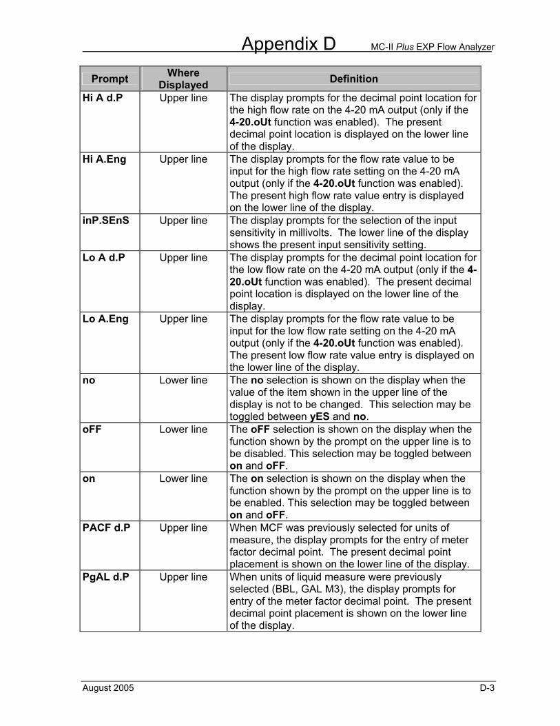
Appendix D MC-II Plus EXP Flow Analyzer
August 2005 D-3
Prompt Where Displayed Definition
Hi A d.P Upper line The display prompts for the decimal point location for the high flow rate on the 4-20 mA output (only if the 4-20.oUt function was enabled). The present decimal point location is displayed on the lower line of the display.
Hi A.Eng Upper line The display prompts for the flow rate value to be input for the high flow rate setting on the 4-20 mA output (only if the 4-20.oUt function was enabled). The present high flow rate value entry is displayed on the lower line of the display.
inP.SEnS Upper line The display prompts for the selection of the input sensitivity in millivolts. The lower line of the display shows the present input sensitivity setting.
Lo A d.P Upper line The display prompts for the decimal point location for the low flow rate on the 4-20 mA output (only if the 4-20.oUt function was enabled). The present decimal point location is displayed on the lower line of the display.
Lo A.Eng Upper line The display prompts for the flow rate value to be input for the low flow rate setting on the 4-20 mA output (only if the 4-20.oUt function was enabled). The present low flow rate value entry is displayed on the lower line of the display.
no Lower line The no selection is shown on the display when the value of the item shown in the upper line of the display is not to be changed. This selection may be toggled between yES and no.
oFF Lower line The oFF selection is shown on the display when the function shown by the prompt on the upper line is to be disabled. This selection may be toggled between on and oFF.
on Lower line The on selection is shown on the display when the function shown by the prompt on the upper line is to be enabled. This selection may be toggled between on and oFF.
PACF d.P Upper line When MCF was previously selected for units of measure, the display prompts for the entry of meter factor decimal point. The present decimal point placement is shown on the lower line of the display.
PgAL d.P Upper line When units of liquid measure were previously selected (BBL, GAL M3), the display prompts for entry of the meter factor decimal point. The present decimal point placement is shown on the lower line of the display.
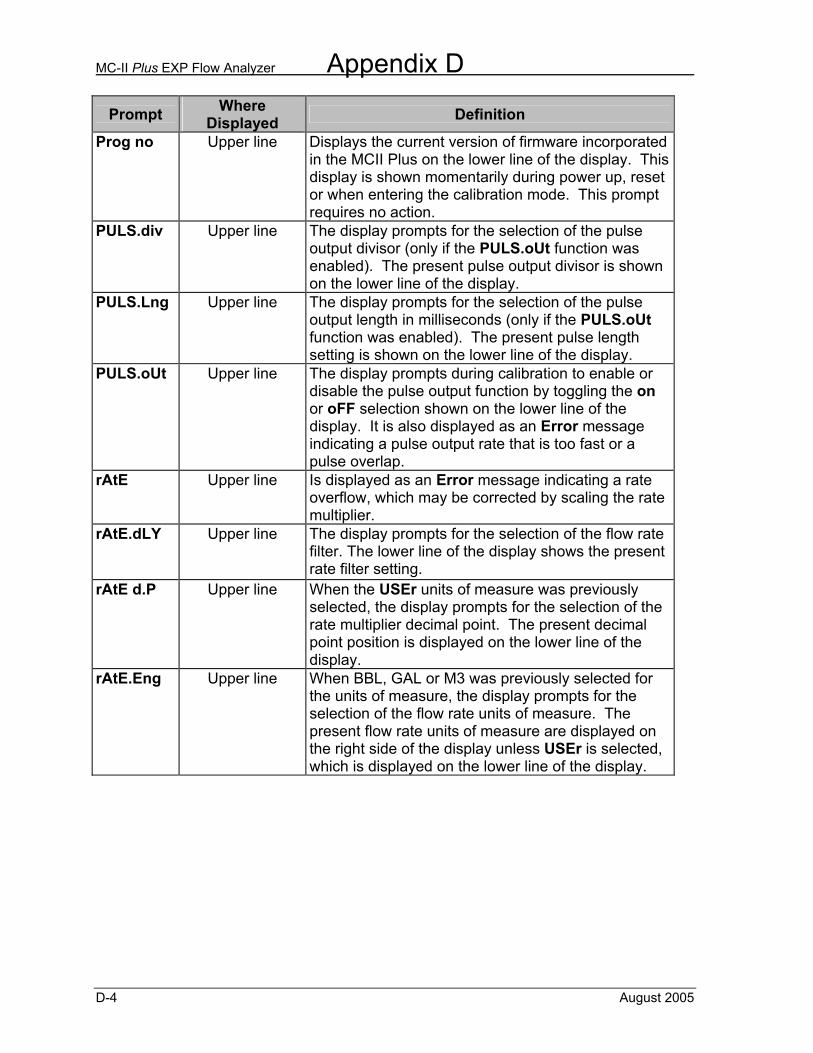
MC-II Plus EXP Flow Analyzer Appendix D
D-4 August 2005
Prompt Where Displayed Definition
Prog no Upper line Displays the current version of firmware incorporated in the MCII Plus on the lower line of the display. This display is shown momentarily during power up, reset or when entering the calibration mode. This prompt requires no action.
PULS.div Upper line The display prompts for the selection of the pulse output divisor (only if the PULS.oUt function was enabled). The present pulse output divisor is shown on the lower line of the display.
PULS.Lng Upper line The display prompts for the selection of the pulse output length in milliseconds (only if the PULS.oUt function was enabled). The present pulse length setting is shown on the lower line of the display.
PULS.oUt Upper line The display prompts during calibration to enable or disable the pulse output function by toggling the on or oFF selection shown on the lower line of the display. It is also displayed as an Error message indicating a pulse output rate that is too fast or a pulse overlap.
rAtE Upper line Is displayed as an Error message indicating a rate overflow, which may be corrected by scaling the rate multiplier.
rAtE.dLY Upper line The display prompts for the selection of the flow rate filter. The lower line of the display shows the present rate filter setting.
rAtE d.P Upper line When the USEr units of measure was previously selected, the display prompts for the selection of the rate multiplier decimal point. The present decimal point position is displayed on the lower line of the display.
rAtE.Eng Upper line When BBL, GAL or M3 was previously selected for the units of measure, the display prompts for the selection of the flow rate units of measure. The present flow rate units of measure are displayed on the right side of the display unless USEr is selected, which is displayed on the lower line of the display.
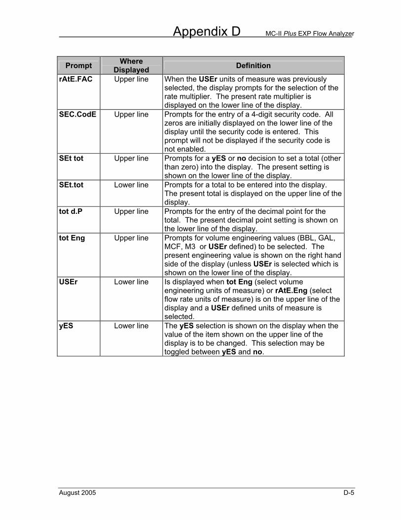
Appendix D MC-II Plus EXP Flow Analyzer
August 2005 D-5
Prompt Where Displayed Definition
rAtE.FAC Upper line When the USEr units of measure was previously selected, the display prompts for the selection of the rate multiplier. The present rate multiplier is displayed on the lower line of the display.
SEC.CodE Upper line Prompts for the entry of a 4-digit security code. All zeros are initially displayed on the lower line of the display until the security code is entered. This prompt will not be displayed if the security code is not enabled.
SEt tot Upper line Prompts for a yES or no decision to set a total (other than zero) into the display. The present setting is shown on the lower line of the display.
SEt.tot Lower line Prompts for a total to be entered into the display. The present total is displayed on the upper line of the display.
tot d.P Upper line Prompts for the entry of the decimal point for the total. The present decimal point setting is shown on the lower line of the display.
tot Eng Upper line Prompts for volume engineering values (BBL, GAL, MCF, M3 or USEr defined) to be selected. The present engineering value is shown on the right hand side of the display (unless USEr is selected which is shown on the lower line of the display.
USEr Lower line Is displayed when tot Eng (select volume engineering units of measure) or rAtE.Eng (select flow rate units of measure) is on the upper line of the display and a USEr defined units of measure is selected.
yES Lower line The yES selection is shown on the display when the value of the item shown on the upper line of the display is to be changed. This selection may be toggled between yES and no.

MC-II Plus EXP Flow Analyzer Appendix D
D-6 August 2005
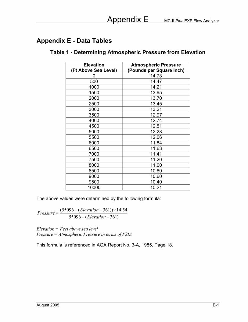
Appendix E MC-II Plus EXP Flow Analyzer
August 2005 E-1
Appendix E - Data Tables
Table 1 - Determining Atmospheric Pressure from Elevation
Elevation (Ft Above Sea Level)
Atmospheric Pressure (Pounds per Square Inch)
0 14.73 500 14.47 1000 14.21 1500 13.95 2000 13.70 2500 13.45 3000 13.21 3500 12.97 4000 12.74 4500 12.51 5000 12.28 5500 12.06 6000 11.84 6500 11.63 7000 11.41 7500 11.20 8000 11.00 8500 10.80 9000 10.60 9500 10.40
10000 10.21
The above values were determined by the following formula:
)361(5509654.14))361(55096(
−+×−−
=Elevation
ElevationPressure
Elevation = Feet above sea level Pressure = Atmospheric Pressure in terms of PSIA This formula is referenced in AGA Report No. 3-A, 1985, Page 18.
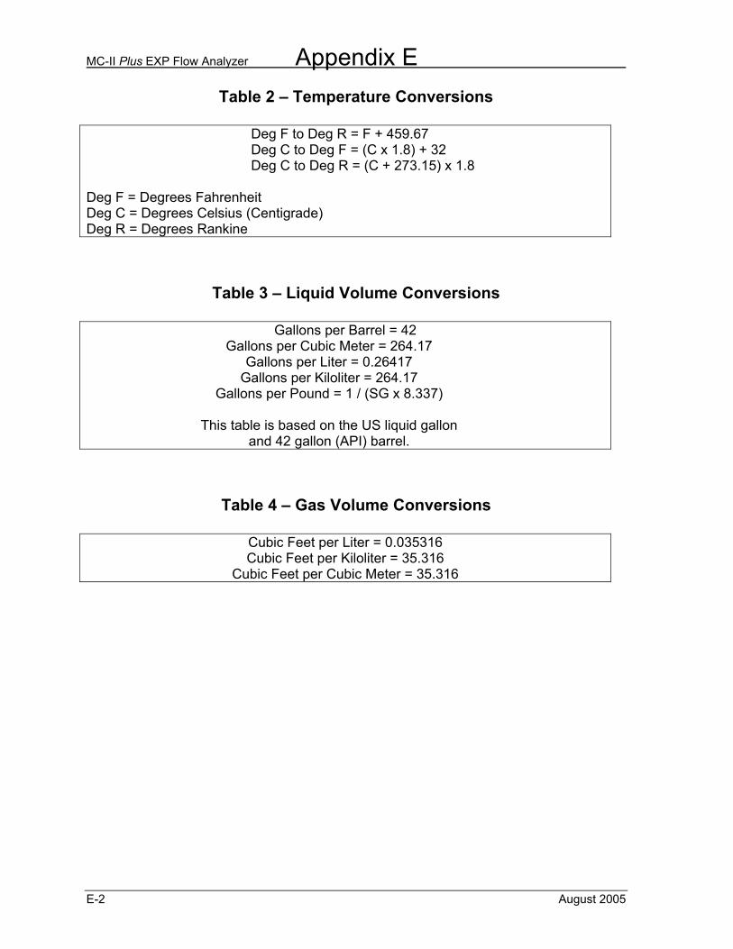
MC-II Plus EXP Flow Analyzer Appendix E
E-2 August 2005
Table 2 – Temperature Conversions Deg F to Deg R = F + 459.67 Deg C to Deg F = (C x 1.8) + 32 Deg C to Deg R = (C + 273.15) x 1.8 Deg F = Degrees Fahrenheit Deg C = Degrees Celsius (Centigrade) Deg R = Degrees Rankine
Table 3 – Liquid Volume Conversions
Gallons per Barrel = 42 Gallons per Cubic Meter = 264.17
Gallons per Liter = 0.26417 Gallons per Kiloliter = 264.17
Gallons per Pound = 1 / (SG x 8.337)
This table is based on the US liquid gallon and 42 gallon (API) barrel.
Table 4 – Gas Volume Conversions
Cubic Feet per Liter = 0.035316 Cubic Feet per Kiloliter = 35.316
Cubic Feet per Cubic Meter = 35.316
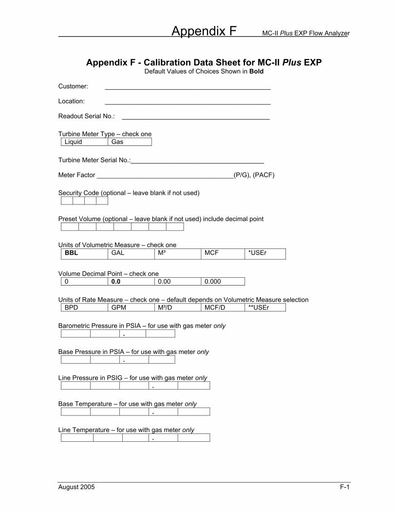
Appendix F MC-II Plus EXP Flow Analyzer
August 2005 F-1
Appendix F - Calibration Data Sheet for MC-II Plus EXP
Default Values of Choices Shown in Bold Customer: ______________________________________________ Location: ______________________________________________ Readout Serial No.: _________________________________________
Turbine Meter Type – check one Liquid Gas
Turbine Meter Serial No.:_____________________________________ Meter Factor ______________________________________(P/G), (PACF)
Security Code (optional – leave blank if not used)
Preset Volume (optional – leave blank if not used) include decimal point
Units of Volumetric Measure – check one
BBL GAL M³ MCF *USEr
Volume Decimal Point – check one
0 0.0 0.00 0.000
Units of Rate Measure – check one – default depends on Volumetric Measure selection
BPD GPM M³/D MCF/D **USEr
Barometric Pressure in PSIA – for use with gas meter only
.
Base Pressure in PSIA – for use with gas meter only
.
Line Pressure in PSIG – for use with gas meter only
.
Base Temperature – for use with gas meter only
.
Line Temperature – for use with gas meter only
.
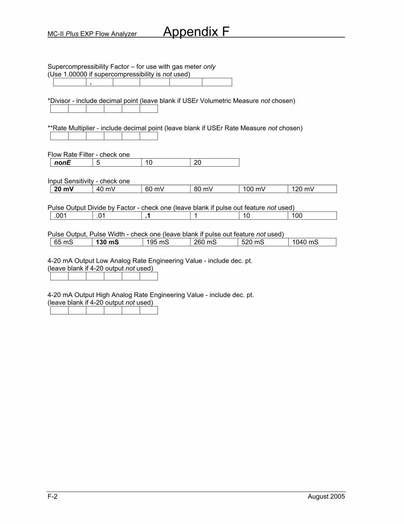
MC-II Plus EXP Flow Analyzer Appendix F
F-2 August 2005
Supercompressibility Factor – for use with gas meter only (Use 1.00000 if supercompressibility is not used)
.
*Divisor - include decimal point (leave blank if USEr Volumetric Measure not chosen)
**Rate Multiplier - include decimal point (leave blank if USEr Rate Measure not chosen)
Flow Rate Filter - check one
nonE 5 10 20
Input Sensitivity - check one
20 mV 40 mV 60 mV 80 mV 100 mV 120 mV
Pulse Output Divide by Factor - check one (leave blank if pulse out feature not used)
.001 .01 .1 1 10 100
Pulse Output, Pulse Width - check one (leave blank if pulse out feature not used)
65 mS 130 mS 195 mS 260 mS 520 mS 1040 mS
4-20 mA Output Low Analog Rate Engineering Value - include dec. pt. (leave blank if 4-20 output not used)
4-20 mA Output High Analog Rate Engineering Value - include dec. pt. (leave blank if 4-20 output not used)
Appendix G MC-II Plus EXP Flow Analyzer
August 2005 G-1
Appendix G – Lithium Battery Information
Lithium Battery Disposal Once a lithium battery is removed from a device and/or is destined for disposal, it is classified as solid waste under EPA guidelines. Depleted lithium batteries are also considered to be hazardous waste because they meet the definition of Reactivity, as per 40 CFR 261.23(a)(2), (3) and (5). This document describes how the lithium reacts violently with water, forms potentially explosive mixtures with water, and when exposed to certain pH conditions, generates toxic cyanide or sulfide gases. Federal law requires that depleted lithium batteries be sent to a fully permitted Treatment, Storage and Disposal Facility (TSDF) or to a permitted recycling/reclamation facility. Important: Do not ship lithium batteries to NuFlo Measurement Systems. NuFlo Measurement Systems facilities are not permitted recycling/reclamation facilities.
Caution: Profiling and waste characterization procedures must be followed prior to shipping a lithium battery to a disposal site. It is the shipper’s responsibility to comply with all applicable federal transportation regulations (see below).
Transportation Information
Warning: The MC-II Plus EXP flow analyzer contains lithium batteries. The internal component (thionyl chloride) is hazardous under the criteria of the Federal OHSA Hazard Communication Standard 29 CFR 1920.1200. Before shipping a lithium battery or equipment containing a lithium battery, verify that the packaging and labeling conforms to the latest version of all applicable regulations.
The transport of the lithium batteries is regulated by the United Nations, “Model Regulations on Transport of Dangerous Goods,” (special provisions 188, 230, and 310), latest revision. Within the US the lithium batteries and cells are subject to shipping requirements under Part 49 of the Code of Federal Regulations (49 CFR, Parts 171, 172, 173, and 175) of the US Hazardous Materials Regulations (HMR), latest revision. Shipping of lithium batteries in aircraft is regulated by the International Civil Aviation Organization (ICAO) and the International Air Transport Association (IATA) requirements in Special Provisions A45, A88 and A99, latest revision.
MC-II Plus EXP Flow Analyzer Appendix G
G-2 August 2005
Shipping of lithium batteries on sea is regulated the International Maritime Dangerous Goods (IMDG) requirements in special provisions 188, 230 and 310, latest revision. Shipping of lithium batteries on road and rail is regulated by requirements in special provisions 188, 230 and 310, latest revision. Material Safety Data Sheet For a link to the current MSDS for the lithium batteries used to power the MC-II Plus EXP Flow Analyzer, see the NuFlo Measurement Systems website: www.nuflotech.com.
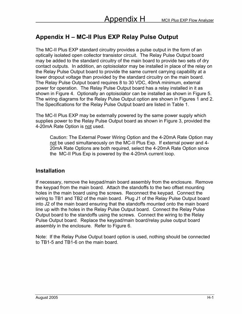
Appendix H MCII Plus EXP Flow Analyzer
August 2005 H-1
Appendix H – MC-II Plus EXP Relay Pulse Output The MC-II Plus EXP standard circuitry provides a pulse output in the form of an optically isolated open collector transistor circuit. The Relay Pulse Output board may be added to the standard circuitry of the main board to provide two sets of dry contact outputs. In addition, an optoisolator may be installed in place of the relay on the Relay Pulse Output board to provide the same current carrying capability at a lower dropout voltage than provided by the standard circuitry on the main board. The Relay Pulse Output board requires 8 to 30 VDC, 40mA minimum, external power for operation. The Relay Pulse Output board has a relay installed in it as shown in Figure 4. Optionally an optoisolator can be installed as shown in Figure 5. The wiring diagrams for the Relay Pulse Output option are shown in Figures 1 and 2. The Specifications for the Relay Pulse Output board are listed in Table 1. The MC-II Plus EXP may be externally powered by the same power supply which supplies power to the Relay Pulse Output board as shown in Figure 3, provided the 4-20mA Rate Option is not used.
Caution: The External Power Wiring Option and the 4-20mA Rate Option may not be used simultaneously on the MC-II Plus Exp. If external power and 4-20mA Rate Options are both required, select the 4-20mA Rate Option since the MC-II Plus Exp is powered by the 4-20mA current loop.
Installation If necessary, remove the keypad/main board assembly from the enclosure. Remove the keypad from the main board. Attach the standoffs to the two offset mounting holes in the main board using the screws. Reconnect the keypad. Connect the wiring to TB1 and TB2 of the main board. Plug J1 of the Relay Pulse Output board into J2 of the main board ensuring that the standoffs mounted onto the main board line up with the holes in the Relay Pulse Output board. Connect the Relay Pulse Output board to the standoffs using the screws. Connect the wiring to the Relay Pulse Output board. Replace the keypad/main board/relay pulse output board assembly in the enclosure. Refer to Figure 6. Note: If the Relay Pulse Output board option is used, nothing should be connected to TB1-5 and TB1-6 on the main board.
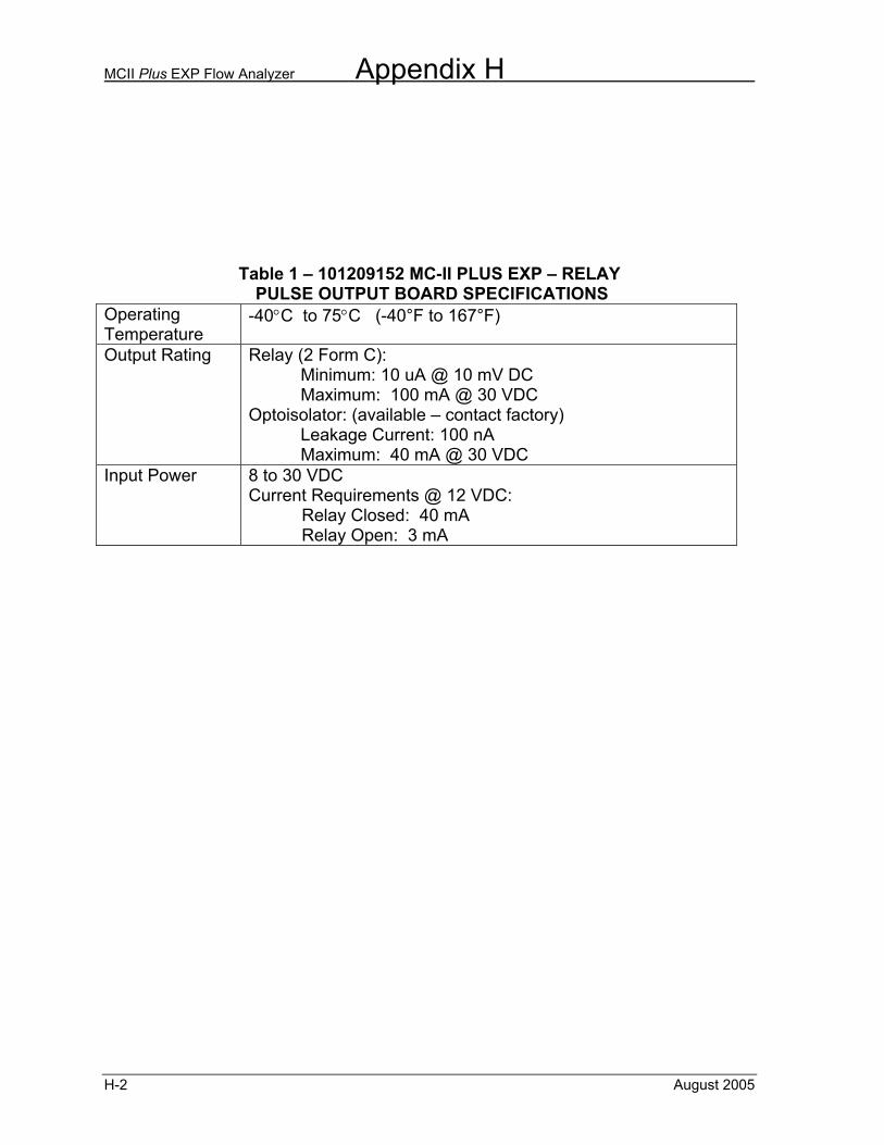
MCII Plus EXP Flow Analyzer Appendix H
H-2 August 2005
Table 1 – 101209152 MC-II PLUS EXP – RELAY PULSE OUTPUT BOARD SPECIFICATIONS
Operating Temperature
-40°C to 75°C (-40°F to 167°F)
Output Rating Relay (2 Form C): Minimum: 10 uA @ 10 mV DC Maximum: 100 mA @ 30 VDC Optoisolator: (available – contact factory) Leakage Current: 100 nA Maximum: 40 mA @ 30 VDC
Input Power 8 to 30 VDC Current Requirements @ 12 VDC: Relay Closed: 40 mA Relay Open: 3 mA
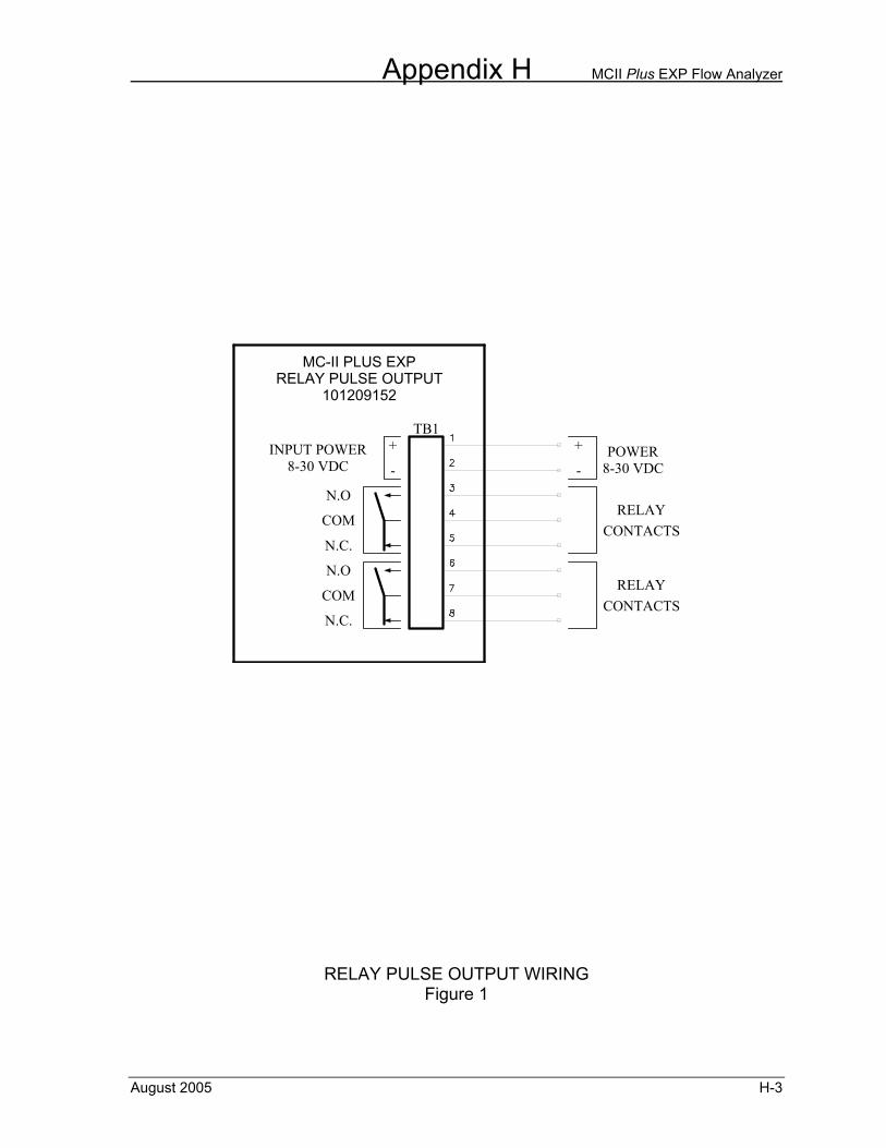
Appendix H MCII Plus EXP Flow Analyzer
August 2005 H-3
COM
N.O
N.C.
COM
N.O
+
-
N.C.
-
+8-30 VDCPOWER
RELAYCONTACTS
RELAYCONTACTS
INPUT POWER8-30 VDC
101209152RELAY PULSE OUTPUT
MC-II PLUS EXP
TB1
RELAY PULSE OUTPUT WIRING Figure 1
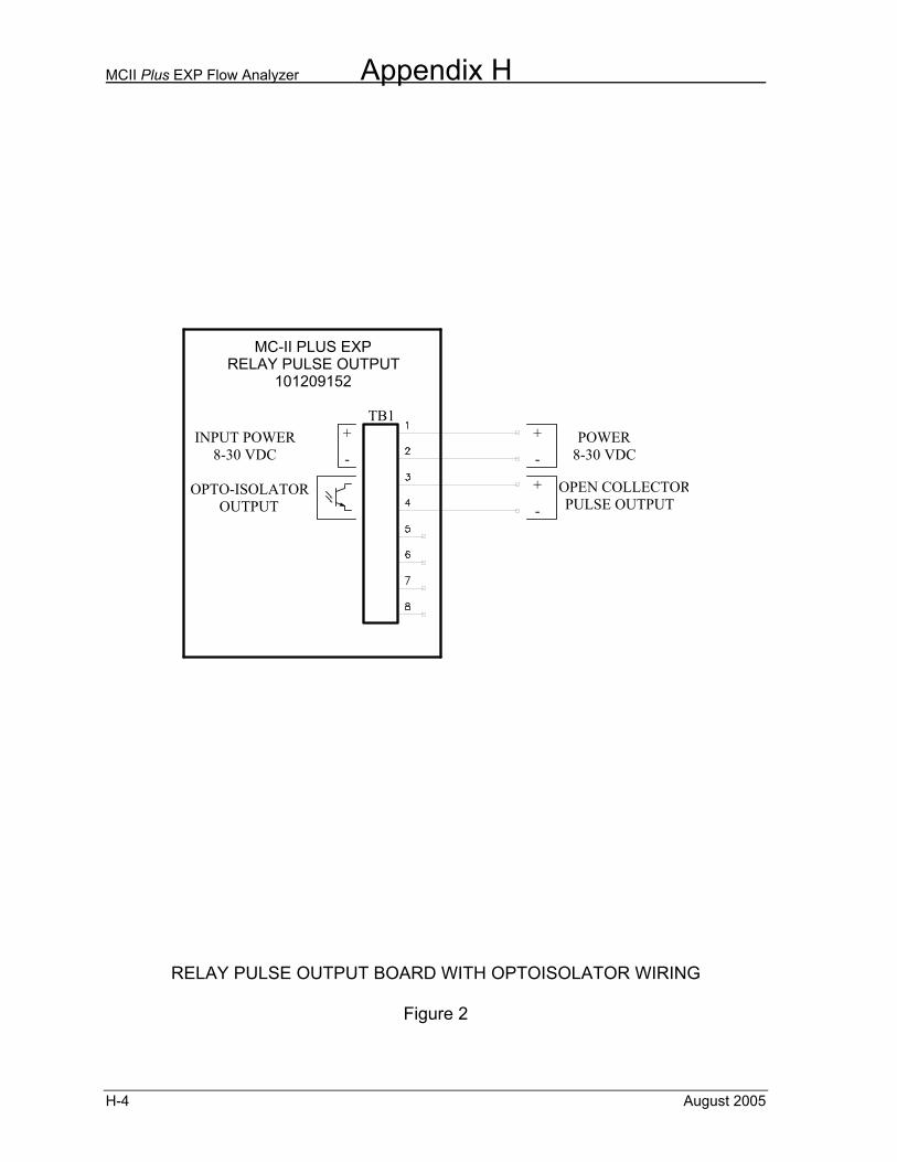
MCII Plus EXP Flow Analyzer Appendix H
H-4 August 2005
INPUT POWER
OUTPUTOPTO-ISOLATOR
8-30 VDC -
+
101209152RELAY PULSE OUTPUT
MC-II PLUS EXP
TB1
OPEN COLLECTORPULSE OUTPUT
+
-
POWER8-30 VDC
+
-
RELAY PULSE OUTPUT BOARD WITH OPTOISOLATOR WIRING
Figure 2

Appendix H MCII Plus EXP Flow Analyzer
August 2005 H-5
MC-II PLUS EXPRELAY PULSE OUTPUT
101209152
MC-II PLUS EXPMAIN BOARD
101001372
TB1
TB2
+
-OUTPUTVCC
+
-REMOTE
RESET
+
-PULSE
OUTPUT
+
-OUTPUT4-20 mA
+
-
AMP &SQUAREOUTPUT
+
-TFM
INPUT
NOTE: NO CONNECTION TO BE MADEAT TB1 PINS 5 AND 6 OFMAIN BOARD, PN 101001372
+
N.C.
-
N.O
COM
N.C.
N.O
COM
TB3
-
+8-30 VDCPOWER
RELAYCONTACTS
RELAYCONTACTS
INPUT POWER8-30 VDC
RELAY PULSE OUTPUT WIRING PROVIDING EXTERNAL POWER TO MAIN BOARD
FIGURE 3
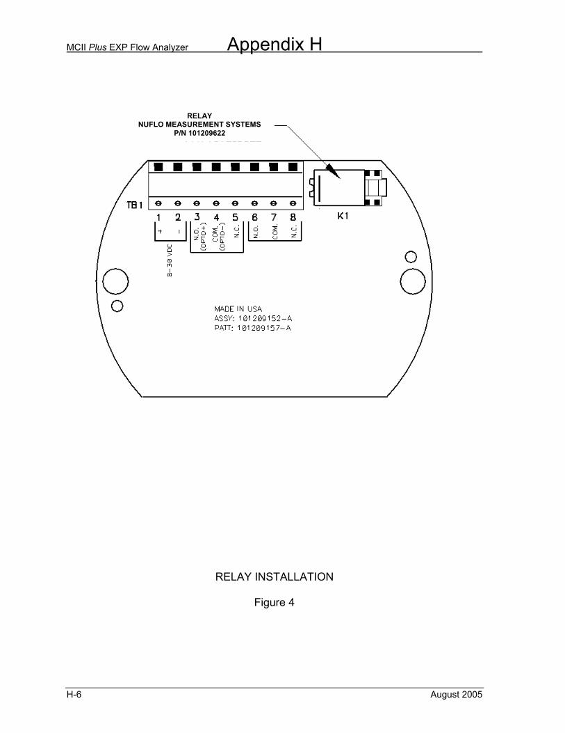
MCII Plus EXP Flow Analyzer Appendix H
H-6 August 2005
RELAY INSTALLATION
Figure 4
NUFLO MEASUREMENT SYSTEMSRELAY
NUFLO MEASUREMENT SYSTEMS P/N 101209622
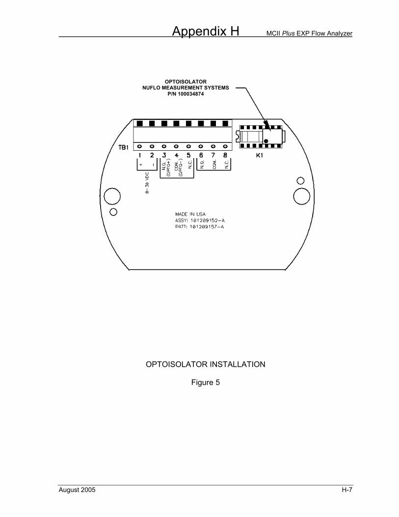
Appendix H MCII Plus EXP Flow Analyzer
August 2005 H-7
OPTOISOLATOR INSTALLATION
Figure 5
NUFLO MEASUREMENT SYSTEMSOPTOISOLATOR
NUFLO MEASUREMENT SYSTEMS P/N 100034874
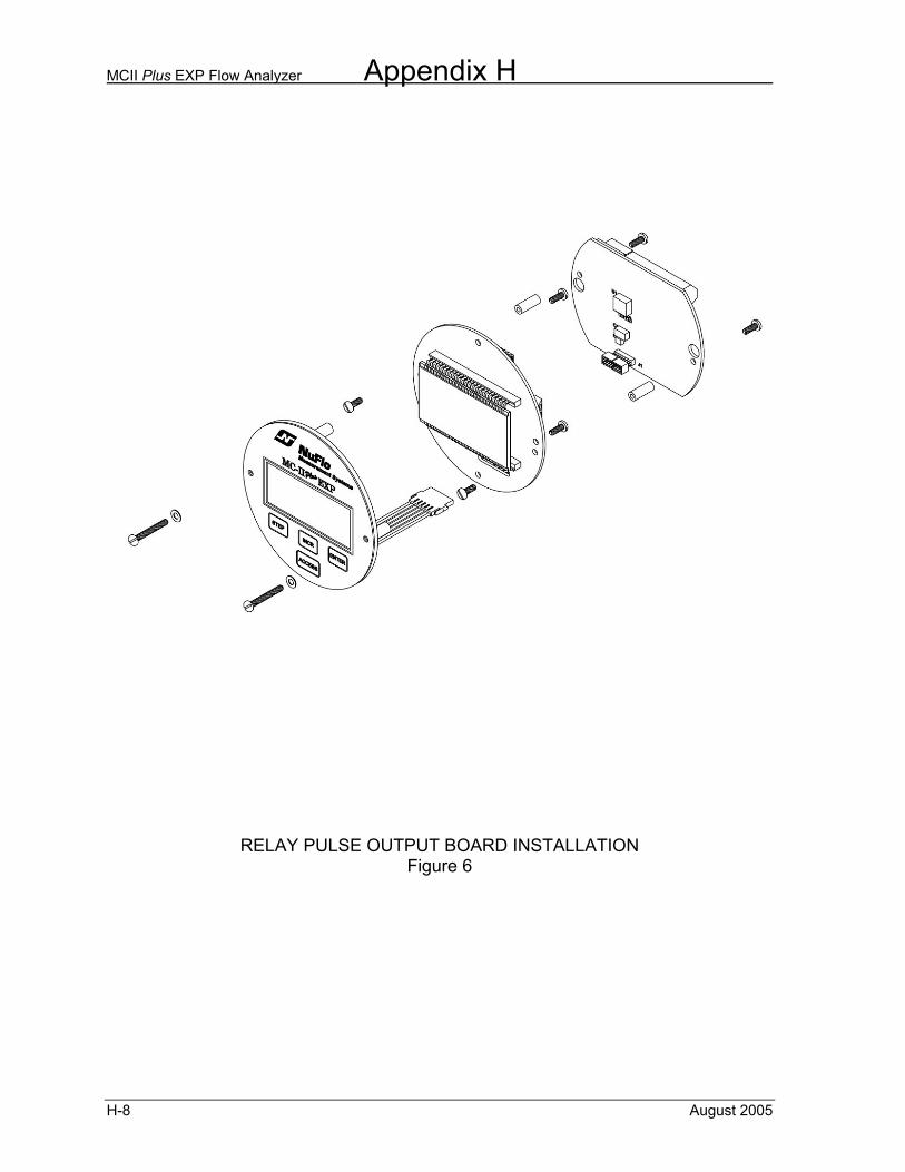
MCII Plus EXP Flow Analyzer Appendix H
H-8 August 2005
RELAY PULSE OUTPUT BOARD INSTALLATION Figure 6
WARRANTY - LIMITATION OF LIABILITY: Seller warrants only title to the products, software, supplies and materials and that, except as to software, the same are free from defects in workmanship and materials for a period of one (1) year from the date of delivery. Seller does not warranty that software is free from error or that software will run in an uninterrupted fashion. Seller provides all software "as is". THERE ARE NO WARRANTIES, EXPRESS OR IMPLIED, OF MERCHANTABILITY, FITNESS OR OTHERWISE WHICH EXTEND BEYOND THOSE STATED IN THE IMMEDIATELY PRECEDING SENTENCE. Seller's liability and Buyer's exclusive remedy in any case of action (whether in contract, tort, breach of warranty or otherwise) arising out of the sale or use of any products, software, supplies, or materials is expressly limited to the replacement of such products, software, supplies, or materials on their return to Seller or, at Seller's option, to the allowance to the customer of credit for the cost of such items. In no event shall Seller be liable for special, incidental, indirect, punitive or consequential damages. Seller does not warrant in any way products, software, supplies and materials not manufactured by Seller, and such will be sold only with the warranties that are given by the manufacturer thereof. Seller will pass only through to its purchaser of such items the warranty granted to it by the manufacturer.