mc10t, mc10ta interface module
TRANSCRIPT

MC10T, MC10TA
Interface module
Technical Specifications
DATA SYSTEMS
HEIM DATaRec® 4 MDR
The HEIM DATaRec® 4 MDR MC10T/MC10TA module is a hybrid module with a combination of 4 internal signal boards. Each signal board is an independent signal part with separate channels. These modular signal board concept in general allows a wide span of channel type combinations and functions.
MDR module with Telemetry Transmit output, PCM input, configurable PCM loopback, Voice input/loopback, PCM signal input and Ethernet signal boards. The assembly options and the function codes for each signal board can be seen per column:
C7A = Telemetry Transmit/PCM input/configurable PCM loopback (C), 75 Ohm single ended termination (7), packed/unpacked and throughput recording modes and filter function (A).
VMB = (MC10TA only) Voice (V), 10 kOhm bias resistor (M) and no additional functions (B).
EBA = Ethernet (E), no assembly options (B) and message filtering (A).
MC10T (SHS511-1001) MC10TA (HS511-1002)
1 Telemetry Transmit data channel on 1 Physical output
1 PCM data channel for recording of theTelemetry Transmit data channel. 2 PCM data channels on
1 Physical input and 1 Physical output;Physical output is configurable: Either E to E loopback from the PCM inputor a second telemetry downlink output (replica of the Telemetry Transmit output)
4 Voice data channels on 4 Physical inputs and 4 Voice Loopback outputs (MC10TA only)
4 Ethernet Data channels on 2 Physical inputs/outputs
© Safran Data Systems GmbH - All trademarks acknowledged. - Safran Data Systems GmbH reserves the right to amend these specifications without notice.Document No.: TS_MC10TMC10TA_200122_T7142R04030.fm Page 1 of 7
MC10T, MC10TA Technical SpecificationsHEIM DATaRec® 4 MDR
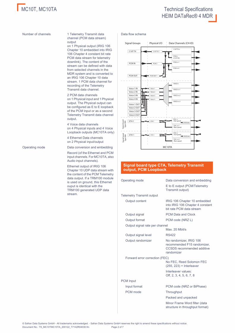
Number of channels 1 Telemetry Transmit data channel (PCM data stream) output on 1 Physical output (IRIG 106 Chapter 10 embedded into IRIG 106 Chapter 4 constant bit rate PCM data stream for telemetry downlink). The content of the stream can be defined with data from selected channels in the MDR system and is converted to an IRIG 106 Chapter 10 data stream. 1 PCM data channel for recording of the Telemetry Transmit data channel.
2 PCM data channels on 1 Physical input and 1 Physical output. The Physical output can be configured as E to E loopback of the PCM input or as a second Telemetry Transmit data channel output.
4 Voice data channels on 4 Physical inputs and 4 Voice Loopback outputs (MC10TA only)
4 Ethernet Data channels on 2 Physical input/output
Operating mode Data conversion and embedding
Record (of the Ethernet and PCM input channels. For MC10TA, also Audio input channels).
Ethernet output of IRIG 106 Chapter 10 UDP data stream with the content of the PCM Telemetry data output. If a TRM100 module is used on ground, this Ethernet ouput is identical with the TRM100 generated UDP data stream.
Data flow schema
Operating mode Data conversion and embedding
E to E output (PCM/Telemetry Transmit output)
Telemetry Transmit output
Output content IRIG 106 Chapter 10 embedded into IRIG 106 Chapter 4 constant bit rate PCM data stream
Output signal PCM Data and Clock
Output format PCM code (NRZ L)
Output signal rate per channelMax. 20 Mbit/s
Output signal level RS422
Output randomizer No randomizer, IRIG 106 recommended F15 randomizer, CCSDS recommended additive randomizer
Forward error correction (FEC)No FEC, Reed Solomon FEC (255, 223) + Interleaver
Interleaver values: Off, 2, 3, 4, 5, 6, 7, 8
PCM Input
Input format PCM code (NRZ or BiPhase)
PCM mode Throughput
Packed and unpacked
Minor Frame Word filter (data structure in throughput format)
Signal board type C7A, Telemetry Transmit output, PCM Loopback
MC10TA
Signal Groups Physical I/O Data Channels (CH-ID)
C10T TX C10T TX n
PCM n(C10T RX)
PCM n+1
PCM n+2
C10T TX 1
PCM IN PCM 2
PCM OUT PCM OUT 1
Voice 2 IN
Voice 3 IN
Voice 1 IN
VOICE n
Voice 1VOICE n+1
Voice 2
VOICE n+2Voice 3
Voice 4 INVOICE n+3
Voice 4
Voice 2 OUT
Voice 3 OUT
Voice 1 OUT
Voice 4 OUT
Sig
na
l bo
ard
typ
e E
BA ETH 1
ETH n
ETH 1
ETH n+1
CH-ID Lists(Full speed)
(Red. speed)
Sig
na
l bo
ard
typ
e E
BA ETH 1
ETH n
ETH 1
ETH n+1
CH-ID Lists(Full speed)
(Red. speed)
© Safran Data Systems GmbH - All trademarks acknowledged. - Safran Data Systems GmbH reserves the right to amend these specifications without notice.Document No.: TS_MC10TMC10TA_200122_T7142R04030.fm Page 2 of 7

MC10T, MC10TA Technical SpecificationsHEIM DATaRec® 4 MDR
Signal rate per channel (R)NRZ-L, -M, -S code: 1 kbit/s to 30 Mbit/s
BiPhase-L, -M, -S code: 10 kbit/s to 10 Mbit/s
Clock source External or internal
Clock rate External: automatic synchronisation to the incoming data rate.
Internal: fixed clock rate in steps (no built-in synchroniser)
Clock edge Rising or falling edge
Interface standards Symmetrical or asymmetrical
Interface standard sym. RS422 or RS485
Symmetrical threshold level ±250 mV (measured at module input, proper terminated)
Asymmetrical threshold levelThreshold selectable in steps from 0 V to 3.3 V
Absolute max. signal −8 V to +13 V (referenced to GND)
Time stamping resolution 100 ns
Input impedance (Termination Low-Z or High-Z; selectable) Low-Z is 75 Ω (asym.)
Low-Z is 100 Ω (sym.)
High-Z is 22 kΩ
Configurable PCM output
Signal level RS422
Output format PCM loopback: As PCM input format
Telemetry output: Replica of the first telemetry output channel
Output clock edge Rising or falling edge (data can also be inverted)
Operating mode Record
E to E loopback
Audio input
Input signal 4 input single ended headset channels
Input ranges 1 Vp, 1Vrms
100 mVp, 100 mVrms
10 mVp, 10 mVrms
Input impedance 10 kΩ
Sampling rate Max. 25 kS/s selectable
Resolution 8 bit / 16 bit
Dynamic range 48 dB (8 bit) / 70 dB (16-bit) 100 mVp and above
48 dB (both 8 and 16 bit) in 10mVp and 10mVrms
Loopback output ranges 1 Vp
100 mVp, 100 mVrms
10 mVp, 10 mVrms
Audio loopback output
Output signal E to E of the 4 audio input channels (output range max. 1 V peak)
Operating mode Record (no E to E)
Input signal 10 / 100 / 1000 Mbit/s Ethernet bus communication
Network interface Ethernet
IEEE 802.3 industry standard
10 Mbps baseband CSMA/CD (10BASE-T)
100 Mbps baseband CSMA/CD (100BASE-TX)
1000 Mbps baseband
Autonegotiation or forced 10/100/1000T mode
Jumbo frames up to 9.6 kByte are supported
Total data rate max. 640 Mbit/s continuously per hybrid module (depending on mainframe/module configuration and channel functions)
For bursts, the total data rate is allowed to be higher than the specified max. total data rate.
Note: Each signal board provides 1 Data Channel unfiltered at max. 640 Mbit/s or filtered (hardware filters) at max. 560 Mbit/s and 1 limited Data Channel unfiltered or filtered (hardware filters) at max. 40 Mbit/s average with max. bursts up to 100 Mbit/s.
Local buffer 512 MByte per hybrid module
Recorded information All frames received on MAC layer, starting with:
Destination address, source address, length, data, FCS (checksum)
The module also records runt packets (frame fragments).
Additional information There are flags available in the data packet for all messages for frame or CRC error, data buffer overflow and Ethernet bus speed
By default, frames >1518 Byte (Jumbo frames) are not marked with an error flag. Jumbo frame error marking is selectable.
Time stamping For each Ethernet MAC frame
Resolution 100ns
Accuracy 1μs
Signal board type VMB, Voice input/loopback
Signal board type EBA, Ethernet data
© Safran Data Systems GmbH - All trademarks acknowledged. - Safran Data Systems GmbH reserves the right to amend these specifications without notice.Document No.: TS_MC10TMC10TA_200122_T7142R04030.fm Page 3 of 7

MC10T, MC10TA Technical SpecificationsHEIM DATaRec® 4 MDR
IP/MAC address The module records all messages received on the Ethernet bus similar to a passive tap.
It will only output data if protocol handling or message generation is enabled.
If protocol handling is enabled, an IPv4 address can be assigned via the parameter setup per physical I/O.
Each physical I/O will also be assigned a factory default MAC address from the Zodiac Data Systems MAC domain which is accessible via the parameter setup .
Supported protocols ARP (MAC and IP address assignment) and ICMP (ping)
Each physical input will actively respond to ARP resolution protocol negotiations. This will allow to send unicast data messages to the module input.
Message generation One freely user programmable message (up to 460 byte long) can be independently transmitted per Physical I/O on the Ethernet bus.
Message header and content is fully user definable (hex-format).
The message transmission rate can be set from 1 ms to 60 seconds in 1 ms steps.
Filter functions Filter types: One choice from: a) Source MAC-address, b) Destination MAC-address, c) Source IPv4-address, d) Destination IPv4-address, e) source UDP port number, f) destination UDP port number, g) one 8,16 or 32-bit field with a fix offset in the data part, h) IENA Key + UDP port.
The module total data rate can drop down to 120 Mbit/s with IENA-filter enabled.
Number of filters = up to 64.
Filter modes = Include or Exclude
Each filter description contains the full information according to the filter type (e. g. no don´t care masks allowed for IP-addresses).
UDP output streaming function (with Telemetry Transmit output)In combination with a Telemetry Transmit output data channel (in the same module), the channel can stream IRIG 106 Chapter 10 UDP data packets defined by channel ID lists.
Power consumption 7W typical; max. 8W
Connector 62-pin HD D-Sub (female),
Dimensions 110 × 19 × 108 mm (w × h × d)
Weight 220g typical
General
© Safran Data Systems GmbH - All trademarks acknowledged. - Safran Data Systems GmbH reserves the right to amend these specifications without notice.Document No.: TS_MC10TMC10TA_200122_T7142R04030.fm Page 4 of 7
MC10T, MC10TA Technical SpecificationsHEIM DATaRec® 4 MDR
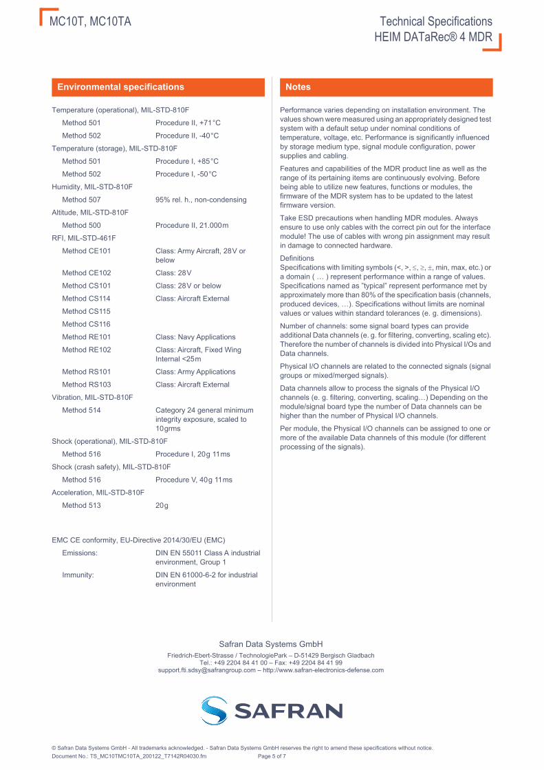
Temperature (operational), MIL-STD-810F
Method 501 Procedure II, +71 °C
Method 502 Procedure II, -40 °C
Temperature (storage), MIL-STD-810F
Method 501 Procedure I, +85 °C
Method 502 Procedure I, -50 °C
Humidity, MIL-STD-810F
Method 507 95% rel. h., non-condensing
Altitude, MIL-STD-810F
Method 500 Procedure II, 21.000 m
RFI, MIL-STD-461F
Method CE101 Class: Army Aircraft, 28 V or below
Method CE102 Class: 28 V
Method CS101 Class: 28 V or below
Method CS114 Class: Aircraft External
Method CS115
Method CS116
Method RE101 Class: Navy Applications
Method RE102 Class: Aircraft, Fixed Wing Internal <25 m
Method RS101 Class: Army Applications
Method RS103 Class: Aircraft External
Vibration, MIL-STD-810F
Method 514 Category 24 general minimum integrity exposure, scaled to 10 grms
Shock (operational), MIL-STD-810F
Method 516 Procedure I, 20 g 11 ms
Shock (crash safety), MIL-STD-810F
Method 516 Procedure V, 40 g 11 ms
Acceleration, MIL-STD-810F
Method 513 20 g
EMC CE conformity, EU-Directive 2014/30/EU (EMC)
Emissions: DIN EN 55011 Class A industrial environment, Group 1
Immunity: DIN EN 61000-6-2 for industrial environment
Performance varies depending on installation environment. The values shown were measured using an appropriately designed test system with a default setup under nominal conditions of temperature, voltage, etc. Performance is significantly influenced by storage medium type, signal module configuration, power supplies and cabling.
Features and capabilities of the MDR product line as well as the range of its pertaining items are continuously evolving. Before being able to utilize new features, functions or modules, the firmware of the MDR system has to be updated to the latest firmware version.
Take ESD precautions when handling MDR modules. Always ensure to use only cables with the correct pin out for the interface module! The use of cables with wrong pin assignment may result in damage to connected hardware.
DefinitionsSpecifications with limiting symbols (<, >, , , , min, max, etc.) or a domain ( … ) represent performance within a range of values. Specifications named as ”typical” represent performance met by approximately more than 80% of the specification basis (channels, produced devices, …). Specifications without limits are nominal values or values within standard tolerances (e. g. dimensions).
Number of channels: some signal board types can provide additional Data channels (e. g. for filtering, converting, scaling etc). Therefore the number of channels is divided into Physical I/Os and Data channels.
Physical I/O channels are related to the connected signals (signal groups or mixed/merged signals).
Data channels allow to process the signals of the Physical I/O channels (e. g. filtering, converting, scaling…) Depending on the module/signal board type the number of Data channels can be higher than the number of Physical I/O channels.
Per module, the Physical I/O channels can be assigned to one or more of the available Data channels of this module (for different processing of the signals).
Environmental specifications Notes
Safran Data Systems GmbHFriedrich-Ebert-Strasse / TechnologiePark – D-51429 Bergisch Gladbach
Tel.: +49 2204 84 41 00 – Fax: +49 2204 84 41 [email protected] – http://www.safran-electronics-defense.com
© Safran Data Systems GmbH - All trademarks acknowledged. - Safran Data Systems GmbH reserves the right to amend these specifications without notice.Document No.: TS_MC10TMC10TA_200122_T7142R04030.fm Page 5 of 7

MC10T, MC10TA Technical SpecificationsHEIM DATaRec® 4 MDR
The HEIM series is a range of tough, versatile and very compact components for flight test recorders and ground based analysis systems. Zodiac Data System provides a special module combination that can be used for data downlink from an airborne recording system to a ground based analysis system.
Following a priciple description of the Telemetry application with the Zodiac Data System product family (with a graphic of an example system).
The HEIM DATaRec® 4 MDR system generates an IRIG106 Chapter 10 Data stream with the data of all channels of captured data for recording. With a Telemetry Downlink module (e. g. MC10T/MC10TA or MTVME-TM7B...) a selection of these channels (of the IRIG106 chapter 10 data stream) can be embedded into an IRIG106 Chapter 7 constant bit rate PCM data stream (telemetry downlink stream). This PCM data stream is fully compatible with standard airborne encryption and RF transmitters (e. g. IRIG Chapter 4 systems) and can be transferred via telemetry (using standard Telemetry transmitter and Telemetry receiver/bit synchronizer).
With a TRM module and/or a GMDR system with a Telemetry receive module (e. g. MTVME-RGGG...) the embedded channels from the telemetry downlink stream can be used for reconstruction of the physical signals, recording or transferring to external processing systems (e. g. PCM decom, Mission audio output, IP-video viewer).
For a principle application example see the following graphic.
Different Receive modules are available.
MTVME-RGGG-... (GMDR module): reproducing the complete transmitted IRIG 106 Chapter 10 data (e. g. for UDP broadcast on ground based networks or for playback with GMDR Playback modules). Additionally, one Ethernet channel, 3 PCM data channels and 4 audio channels can be picked up from the IRIG106 Chapter 10 data stream and be physically reconstructed (Gateway mode).
TRM100: reproducing the complete transmitted IRIG 106 Chapter 10 data (e. g. for UDP broadcast on ground based networks). Additionally, one Ethernet channel and one PCM data channel can be picked up from the IRIG106 Chapter 10 data stream and be physically reconstructed (Gateway mode).
TRM200: physically reconstruction of 4 x video streams with embedded stereo audio channels on DVI-D interfaces and 2 audio channels (Gateway mode). The supported video streams are compatible with the MVCRx modules of the MDR series.
TRM300: extracting up to 7 independent PCM streams (collected by any PCM channels of the MDR) and physically reconstruct them (Gateway mode).
In combination with the TRM module family, two configurations are possible:
Stand-alone configuration: The IRIG 106 Chapter 7 data stream is led directly to each TRM module.
Daisy Chain configuration: The IRIG 106 Chapter 7 data stream is led to one TRM module. Every TRM module has an E to E output of the incoming telemetry data stream (for TRM100 the PCM output channel is either e-to-e or Gateway output). A serial daisy chain with further TRM modules can be configured.
Application note
MDR with MC10T/TA or MTVME-TM7B-...
GMDR with MTVME-RGGG-...
Playback modules (Gateway mode)reconstruction of all data types supported
by GMDR playback modulese. g.: ARINC429, MIL1553B, Video, PCM, ...
Reconstructed physical signals
MTVME-RGGG...module
Gateway signal boards
MC10T/TA or MTVME-TM7B... module
IRIG 106 Chapter10 data streamse. g.: ARINC429, MIL1553B, Video, PCM, ...
Telemetry receiverand bit
synchronizer
Telemetry transmitter
Sensor data(all data types supported by MDR modules
e.g. ARINC429, MIL1553B,
Video, PCM)
IRIG106 Chapter 10UDP data streaming
Ethernet
Mission audio
IRIG 106 Chapter7 data stream
IRIG 106 Chapter4 constant bit rate stream
PCM data
PCM data
PCM data
Ethern
et
Recording
PCMIRIG 106 Chapter10 data streamse. g.: ARINC429, MIL1553B, Video, PCM, ...
PCM Decom
Audio
RMM
DVI -Video Mission audio (low latency, <20ms)
PCM
PCM Decom
IRIG 106 Chapter7 data stream
IRIG 106 Chapter4 constant bit rate stream
AARI
NC
4C
4C
4C
4C
4C
4C
4C
4C
4C
4C
4C
4C
4C
4C
4C
4C
4CC
44429229292922
MIL
1L1L1L1LLLLLLLLLLLLLLLLLLLLLLLLLLLLLLLLL5
55
55
55
55
3B
3BBB
3B
3
IP camera videovia Ethernet
ZDS-Viewer
IP camera1
IP camera3
IP camera2
IP camera4
PCM data
Ethernet
IRIG106 Chapter 10UDP data streaming
Mission audio
SD/HD video data (incl. stereo audio)
PCM data
PCM data
PCM data
PCM data
PCM data
PCM data
PCM data
TRM100 TRM200 TRM300
Daisy chain telemetry streamm Daisy chain telemetry streamm
Daisy ChainZDS-Viewer
IRIG 106 Chapter7 data stream
IRIG 106 Chapter4 constant bit rate stream
© Safran Data Systems GmbH - All trademarks acknowledged. - Safran Data Systems GmbH reserves the right to amend these specifications without notice.Document No.: TS_MC10TMC10TA_200122_T7142R04030.fm Page 6 of 7

MC10T, MC10TA Technical SpecificationsHEIM DATaRec® 4 MDR
Modul uses HD-DSUB 62 Pin Male Plug (CTZ37-62P1 from FCT)
Connector Pin out
Pin Nr. Description
22 Common ground
1 C10T_TX output Data-
43 C10T_TX output Clock-
23 C10T_TX output Data+
2 PCM input Clock-
44 C10T_TX output Clock+
24 PCM input Clock+
3 PCM input Data-
45 C10T_TX output signal ground
25 PCM input Data+
4 PCM output or 2. C10T_TX output (replica of 1. C10T_TX) Clock-
46 PCM input signal ground
26 PCM output or 2. C10T_TX output (replica of 1. C10T_TX) Clock+
5 PCM output or 2. C10T_TX output (replica of 1. C10T_TX) Data-
47 PCM output signal ground
27 PCM output or 2. C10T_TX output (replica of 1. C10T_TX) Data+
6 Voice 1 Output (MC10TA)
48 Voice 4 Output (MC10TA)
28 Voice 1 GND (MC10TA)
7 Voice 1 Input (MC10TA)
49 Voice 4 Input (MC10TA)
29 Voice 4 GND (MC10TA)
8 GND (MC10TA)
50 GND (MC10TA)
30 Voice 2 GND (MC10TA)
9 Voice 2 Input (MC10TA)
51 Voice 3 Input (MC10TA)
31 Voice 3 GND (MC10TA)
10 Voice 2 Output (MC10TA)
52 Voice 3 Output (MC10TA)
32 GND (MC10TA)
11 ETH 1 Gigabit Ethernet Case / Shield
53 Reserved/Not connected
33 Reserved/Not connected
12 ETH 1 Gigabit Ethernet Data 0-
54 Reserved/Not connected
34 ETH 1 Gigabit Ethernet Data 0+
13 ETH 1 Gigabit Ethernet Data 1-
55 Reserved/Not connected
35 ETH 1 Gigabit Ethernet Data 1+
14 ETH 1 Gigabit Ethernet Data 2-
56 Reserved/Not connected
36 ETH 1 Gigabit Ethernet Data 2+
15 ETH 1 Gigabit Ethernet Data 3-
57 Reserved/Not connected
37 ETH 1 Gigabit Ethernet Data 3+
16 ETH 2 Gigabit Ethernet Case / Shield
58 Reserved/Not connected
38 Reserved/Not connected
17 ETH 2 Gigabit Ethernet Data 0-
59 Reserved/Not connected
39 ETH 2 Gigabit Ethernet Data 0+
18 ETH 2 Gigabit Ethernet Data 1-
60 Reserved/Not connected
40 ETH 2 Gigabit Ethernet Data 1+
19 ETH 2 Gigabit Ethernet Data 2-
61 Reserved/Not connected
41 ETH 2 Gigabit Ethernet Data 2+
20 ETH 2 Gigabit Ethernet Data 3-
62 Reserved/Not connected
42 ETH 2 Gigabit Ethernet Data 3+
21 Common ground
© Safran Data Systems GmbH - All trademarks acknowledged. - Safran Data Systems GmbH reserves the right to amend these specifications without notice.Document No.: TS_MC10TMC10TA_200122_T7142R04030.fm Page 7 of 7