mc3090-z rfid mobile computer integrator guide, p/n 72e ... · configuration menu options ... zebra...
TRANSCRIPT
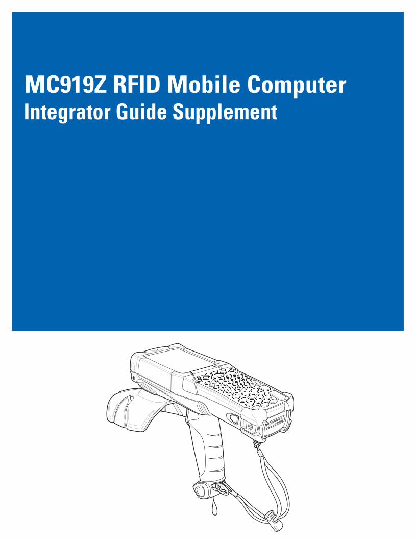
MC919Z RFID Mobile ComputerIntegrator Guide Supplement


MC919Z Integrator Guide Supplement
72E-157455-02Rev A
March 2015

ii MC919Z Integrator Guide Supplement
© 2015 Symbol Technologies, Inc.
No part of this publication may be reproduced or used in any form, or by any electrical or mechanical means, without permission in writing from Zebra. This includes electronic or mechanical means, such as photocopying, recording, or information storage and retrieval systems. The material in this manual is subject to change without notice.
The software is provided strictly on an “as is” basis. All software, including firmware, furnished to the user is on a licensed basis. Zebra grants to the user a non-transferable and non-exclusive license to use each software or firmware program delivered hereunder (licensed program). Except as noted below, such license may not be assigned, sublicensed, or otherwise transferred by the user without prior written consent of Zebra. No right to copy a licensed program in whole or in part is granted, except as permitted under copyright law. The user shall not modify, merge, or incorporate any form or portion of a licensed program with other program material, create a derivative work from a licensed program, or use a licensed program in a network without written permission from Zebra. The user agrees to maintain Zebra’s copyright notice on the licensed programs delivered hereunder, and to include the same on any authorized copies it makes, in whole or in part. The user agrees not to decompile, disassemble, decode, or reverse engineer any licensed program delivered to the user or any portion thereof.
Zebra reserves the right to make changes to any software or product to improve reliability, function, or design.
Zebra does not assume any product liability arising out of, or in connection with, the application or use of any product, circuit, or application described herein.
No license is granted, either expressly or by implication, estoppel, or otherwise under any Zebra Technologies Corporation., intellectual property rights. An implied license only exists for equipment, circuits, and subsystems contained in Zebra products.
Zebra and the Zebra head graphic are registered trademarks of ZIH Corp. The Symbol logo is a registered trademark of Symbol Technologies, Inc., a Zebra Technologies company.
Zebra Technologies CorporationLincolnshire, IL U.S.A.http://www.zebra.com
iii
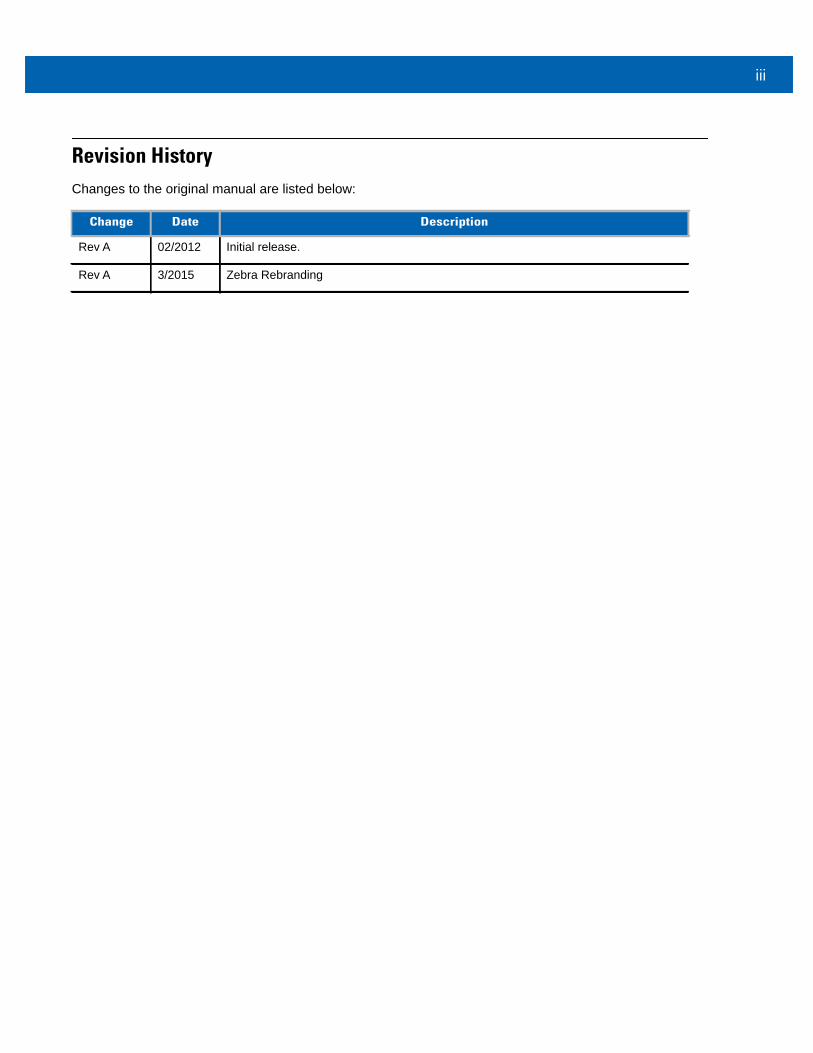
Revision HistoryChanges to the original manual are listed below:
Change Date Description
Rev A 02/2012 Initial release.
Rev A 3/2015 Zebra Rebranding

iv MC919Z Integrator Guide Supplement
Table of Contents
Revision History............................................................................................................. iii
Table of Contents
About This GuideIntroduction .................................................................................................................... ixConfigurations................................................................................................................ ixChapter Descriptions ..................................................................................................... xNotational Conventions.................................................................................................. xRelated Documents and Software ................................................................................. xiService Information........................................................................................................ xi
Chapter 1: Getting StartedIntroduction ................................................................................................................... 1-1RFID Technology Overview .......................................................................................... 1-1
RFID Components .................................................................................................. 1-2MC919Z RFID Mobile Computer .................................................................................. 1-3MC919Z Parts ............................................................................................................... 1-4
MC919Z LED Indicators .......................................................................................... 1-5Reading Tags ............................................................................................................... 1-5
Chapter 2: Updating the RFID Mobile ComputerIntroduction ................................................................................................................... 2-1Updating the Device Image .......................................................................................... 2-1
Downloading an Update Loader Package .............................................................. 2-1Updating Images via ActiveSync ............................................................................ 2-1
Updating the RFID Firmware ........................................................................................ 2-2
vi MC919Z Integrator Guide Supplement
Chapter 3: MobileRFID FunctionalityIntroduction ................................................................................................................... 3-1MobileRFID Icons ......................................................................................................... 3-2MobileRFID Menu ......................................................................................................... 3-3
Configure Region .................................................................................................... 3-4Configure RFID ....................................................................................................... 3-7Version Information ................................................................................................. 3-8Run/Stop RFID ........................................................................................................ 3-9
Chapter 4: RFID Sample ApplicationIntroduction ................................................................................................................... 4-1Launching the RFID Sample Application ...................................................................... 4-2Connection .................................................................................................................... 4-3Capabilities ................................................................................................................... 4-4Configuration Menu Options ......................................................................................... 4-5
Tag Storage Settings .............................................................................................. 4-5Antenna ................................................................................................................... 4-6RF Mode ................................................................................................................. 4-7Singulation .............................................................................................................. 4-8Power On/Off Radio ................................................................................................ 4-9Reset to Factory Default ......................................................................................... 4-9
Operations Menu Options ............................................................................................. 4-10Antenna Info ............................................................................................................ 4-10Filter ........................................................................................................................ 4-11Access .................................................................................................................... 4-14Triggers ................................................................................................................... 4-19
Management Menu Options ......................................................................................... 4-26Help Menu .................................................................................................................... 4-26Exit ................................................................................................................................ 4-26
Chapter 5: Tag Locator Introduction ................................................................................................................... 5-1Using Tag Locator ........................................................................................................ 5-2Locating Tags Using a .csv File .................................................................................... 5-3
Chapter 6: TroubleshootingIntroduction ................................................................................................................... 6-1Troubleshooting ............................................................................................................ 6-1
MC919Z .................................................................................................................. 6-1Bluetooth Connection .............................................................................................. 6-3Four Slot Charge Only Cradle ................................................................................. 6-4Four Slot Ethernet Cradle ....................................................................................... 6-4Four Slot Spare Battery Charger ............................................................................ 6-6Single Slot Serial/USB Cradle ................................................................................. 6-6Cable Adapter Module ............................................................................................ 6-7Magnetic Stripe Reader .......................................................................................... 6-8Modem Module ....................................................................................................... 6-9
Table of Contents vii
Appendix A: Technical SpecificationsMC919Z Specifications ................................................................................................. A-1
Decode Zones ......................................................................................................... A-5SE960 Standard Range Laser Decode Zones ........................................................ A-5SE1524 Long Range Laser Decode Zones ............................................................ A-7SE4500 Standard Range Imager Decode Zones ................................................... A-9Mobile Computer Pin-Outs ...................................................................................... A-13
Accessory Specifications .............................................................................................. A-14Single Slot Serial/USB Cradle ................................................................................. A-14Four Slot Ethernet Cradle ....................................................................................... A-14Four Slot Charge Only Cradle ................................................................................. A-15Four Slot Battery Charger ....................................................................................... A-15Magnetic Stripe Reader .......................................................................................... A-16Accessory CAM and MSR Pin-Outs ....................................................................... A-17
Appendix B: RFID APIs
Index

viii MC919Z Integrator Guide Supplement
About This Guide
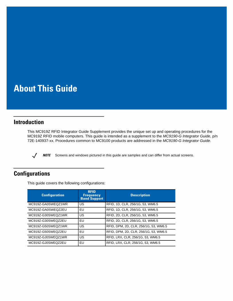
IntroductionThis MC919Z RFID Integrator Guide Supplement provides the unique set up and operating procedures for the MC919Z RFID mobile computers. This guide is intended as a supplement to the MC9190-G Integrator Guide, p/n 72E-140937-xx. Procedures common to MC9100 products are addressed in the MC9190-G Integrator Guide.
ConfigurationsThis guide covers the following configurations:
NOTE Screens and windows pictured in this guide are samples and can differ from actual screens.
ConfigurationRFID
FrequencyBand Support
Description
MC919Z-GA0SWEQZ1WR US RFID, 1D, CLR, 256/1G, 53, WM6.5
MC919Z-GA0SWEQZ2EU EU RFID, 1D, CLR, 256/1G, 53, WM6.5
MC919Z-G30SWEQZ1WR US RFID, 2D, CLR, 256/1G, 53, WM6.5
MC919Z-G30SWEQZ2EU EU RFID, 2D, CLR, 256/1G, 53, WM6.5
MC919Z-G50SWEQZ1WR US RFID, DPM, 2D, CLR, 256/1G, 53, WM6.5
MC919Z-G50SWEQZ2EU EU RFID, DPM, 2D, CLR, 256/1G, 53, WM6.5
MC919Z-GJ0SWEQZ1WR US RFID, LRX, CLR, 256/1G, 53, WM6.5
MC919Z-GJ0SWEQZ2EU EU RFID, LRX, CLR, 256/1G, 53, WM6.5
x MC919Z Integrator Guide Supplement
Chapter DescriptionsTopics covered in this guide are as follows:
• Chapter 1, Getting Started provides an overview of RFID technology and components, and a description of the MC919Z RFID mobile computer and features.
• Chapter 2, Updating the RFID Mobile Computer describes how to update the device image and radio firmware.
• Chapter 3, MobileRFID Functionality includes information on configuring the RFID radio and reading tags.
• Chapter 4, RFID Sample Application provides information on the RFID sample application and how to use it to assist in custom application development.
• Chapter 5, Tag Locator provides information on the application used to detect the location of a tag.
• Chapter 6, Troubleshooting describes MC919Z RFID mobile computer troubleshooting procedures.
• Appendix A, Technical Specifications includes the technical specifications for the reader.
• Appendix B, RFID APIs provides a reference for information on supported RFID APIs.
Notational ConventionsThe following conventions are used in this document:
• “Mobile computer” refers to the MC919Z hand-held computer.
• Italics are used to highlight the following:• Chapters and sections in this guide• Related documents
• Bold text is used to highlight the following:• Dialog box, window and screen names• Drop-down list and list box names• Check box and radio button names• Icons on a screen• Key names on a keypad• Button names on a screen.
• Bullets (•) indicate:• Action items• Lists of alternatives• Lists of required steps that are not necessarily sequential.
• Sequential lists (e.g., those that describe step-by-step procedures) appear as numbered lists.
About This Guide xi
Related Documents and SoftwareThe following documents provide more information about the MC919Z.
• MC919Z Quick Start Guide, p/n 72-152191-xx
• MC919Z Regulatory Guide, p/n 72-157453-xx
• MC9190-G User Guide, p/n 72E-140936-xx
• MC9190-G Integrator Guide, p/n 72E-140937-xx
• Enterprise Mobility Developer Kits, available at: http://www.zebra.com/support.
• Microsoft Sync software, available at: http://www.microsoft.com.
For the latest version of this guide and all guides, go to: http://www.zebra.com/support.
Service InformationIf you have a problem with your equipment, contact Zebra for your region. Contact information is available at: http://www.zebra.com/support.
When contacting Zebra support, please have the following information available:
• Serial number of the unit
• Model number or product name
• Software type and version number
Zebra responds to calls by e-mail, telephone or fax within the time limits set forth in service agreements.
If your problem cannot be solved by Zebra support, you may need to return your equipment for servicing and will be given specific directions. Zebra is not responsible for any damages incurred during shipment if the approved shipping container is not used. Shipping the units improperly can possibly void the warranty.
If you purchased your business product from a Zebra business partner, please contact that business partner for support.

xii MC919Z Integrator Guide Supplement
Chapter 1 Getting Started
IntroductionThis chapter provides an overview of RFID technology and components, and describes the MC919Z RFID mobile computer and product features.
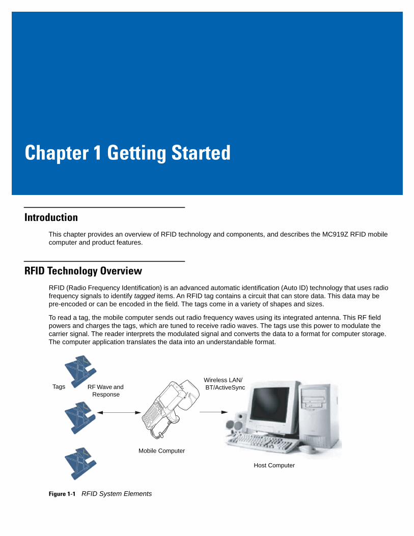
RFID Technology OverviewRFID (Radio Frequency Identification) is an advanced automatic identification (Auto ID) technology that uses radio frequency signals to identify tagged items. An RFID tag contains a circuit that can store data. This data may be pre-encoded or can be encoded in the field. The tags come in a variety of shapes and sizes.
To read a tag, the mobile computer sends out radio frequency waves using its integrated antenna. This RF field powers and charges the tags, which are tuned to receive radio waves. The tags use this power to modulate the carrier signal. The reader interprets the modulated signal and converts the data to a format for computer storage. The computer application translates the data into an understandable format.
Figure 1-1 RFID System Elements
Host Computer
Tags
Mobile Computer
Wireless LAN/ BT/ActiveSyncRF Wave and
Response

1 - 2 MC919Z Integrator Guide Supplement
RFID Components
Zebra RFID solutions offer low cost, long read range, and a high read rate. These features provide real time end-to-end visibility of products and assets in the factory, distribution center, retail outlet, or other facility. The MC919Z RFID system consists of the following components:
• Silicon-based RFID tags that attach to retail products, vehicles, trailers, containers, pallets, boxes, etc.
• An integrated antenna that supports applications such as item level tracking and asset tracking.
• An embedded radio module that powers and communicates with tags for data capture and provides host connectivity for data migration.
Tags
Tags contain embedded chips that store unique information. Available in various shapes and sizes, tags, often called transponders, receive and respond to data requests. Tags require power to send data.
There are several categories of tags based on the protocol they support, read/write memory, and power options:
• Active RFID tags are powered by internal light-weight batteries, and also use these batteries to broadcast radio waves to the reader.
• Semi-passive RFID tags are also powered by internal light-weight batteries, but draw broadcasting power from the reader.
• Passive RFID tags are powered by a reader-generated RF field. These tags are much lighter and less expensive than active tags, and are typically applied to less expensive goods.
Antenna
Antennas transmit and receive radio frequency signals.
Radio Module
The radio module communicates with the tags and transfers the data to a host computer. It also provides features such as filtering, CRC check, and tag writing. The MC919Z RFID mobile computer supports standard RFID tags as described by EPCGlobalTM Class 1 Gen2 protocol.
Getting Started 1 - 3
MC919Z RFID Mobile ComputerThe Zebra MC919Z RFID mobile computer includes an intelligent C1G2 UHF RFID reader with RFID read performance that provides real-time, seamless EPC-compliant tag processing. MC919Z RFID mobile computers are designed for back room inventory management, manufacturing floors, inside/outside loading dock and asset tracking applications, and can host third-party, customer-driven embedded applications. Features include:
• ISO 18000-6C standard (EPC Class 1 Gen 2)
• Read, write, kill, lock, block write/block erase, and permalock functionality
• 53-key alphanumeric keypad
• 3.7” VGA color display
• Touch panel with 340 dpi resolution
• Orientation-insensitive integrated external RFID antenna
• Reads 1D and 2D bar codes
• Windows® Mobile 6.5
• WLAN 802.11 a/b/g wireless connectivity
• Application-specific setup for ease of installation
• Low Level Reader Protocol (LLRP) - For LLRP custom extensions, refer to the Software Interface Guide p/n 72E-131718-XX.
• Sample application and support for custom or third-party applications
• RFID API support
• Event and tag management support
Figure 1-2 MC919Z RFID Mobile Computer
1 - 4 MC919Z Integrator Guide Supplement
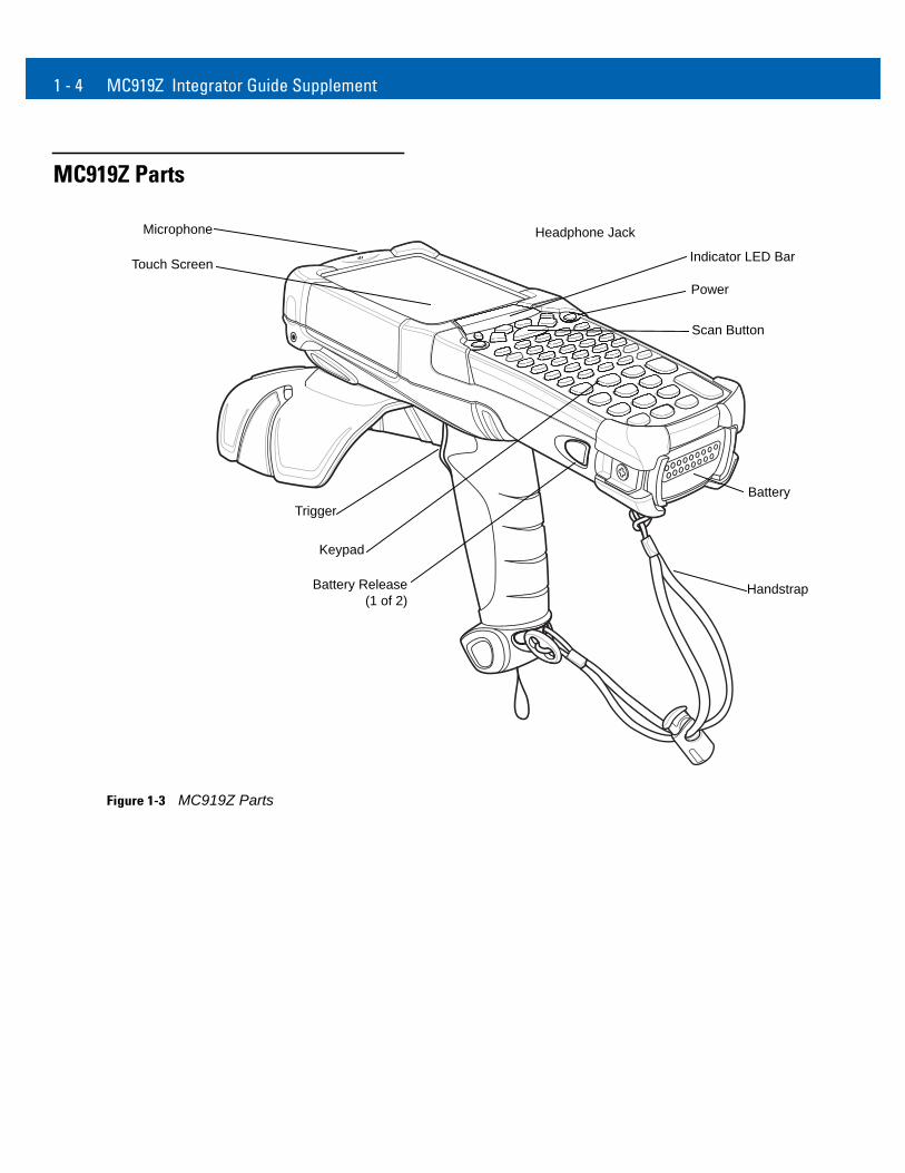
MC919Z Parts
Figure 1-3 MC919Z Parts
Indicator LED Bar
Power
BatteryTrigger
Microphone
Touch Screen
Scan Button
Headphone Jack
Keypad
HandstrapBattery Release(1 of 2)
Getting Started 1 - 5
MC919Z LED Indicators
The LEDs indicate charging and reader status as described in Table 1-1.
Reading TagsTo read RFID tags:
1. Remove the MC919Z from AC power and ensure the LLRP icon is green.
2. Use an RFID reader application to enable tag reading. For a sample application, tap on icon RFID Demo in the start menu, or browse to the MC919Z Application directory and select CS_RFID3Sample6.exe. See RFID Sample Application on page 4-1.
3. Aim the mobile computer at the tag, oriented horizontally or vertically depending on the tag orientation. The distance between the tag and the antenna is the approximate read range.
Press the trigger or tap the on-screen Read command within the application to interrogate all RFID tags within the radio frequency (RF) field of view and capture data from each new tag found. Release the trigger or tap the Stop Read command to stop interrogating tags.
Table 1-1 MC919Z LED Status Indicators
LED Indication
Charging Indicators
Off Mobile computer not placed correctly in the cradle; cable not connected correctly; charger not powered.
Fast Blinking Amber Error in charging; check placement of mobile computer.
Slow Blinking Amber Mobile computer is charging.
Solid Amber Charging complete.Note: When the battery is initially inserted in the mobile computer, the amber LED flashes once if the battery power is low or the battery is not fully inserted.
NOTE When connected to power, the mobile computer cannot read RFID tags.

1 - 6 MC919Z Integrator Guide Supplement
Chapter 2 Updating the RFID MobileComputer
IntroductionThis chapter describes how to update the device image and radio firmware.
Updating the Device ImageWindows Mobile contains an Image Update feature that updates all operating system components. Zebra distributes all updates as update packages on the Support Central Web Site http://www.zebra.com/support. These packages contain either partial or complete updates for the operating system.
To update an operating system component, copy the update package to the mobile computer using ActiveSync or MSP.
Downloading an Update Loader Package
1. Download the appropriate update loader package from the Zebra Support Central web site http://www.zebra.com/support to a host computer.
2. Locate the update loader package file on the host computer and un-compress the file into a separate directory:9190w65HenULxxxxx.zip for updating via ActiveSync
Updating Images via ActiveSync
To install an update loader package using ActiveSync:
1. Insert the mobile computer into the cradle and connect the cradle to AC power.
2. Connect the mobile computer to the host computer using ActiveSync.
3. In ActiveSync on the host computer, open Explorer on the mobile computer.
4. Copy the contents of xxxxw65xenULxxxxxX\UpdateLoader (the files only, not the folder) into the \Storage Card folder on the mobile computer. For example, the name for the MC9190Z is 9190w65HenUL024103\UpdateLoader.
2 - 2 MC919Z Integrator Guide Supplement
5. On the mobile computer, navigate to the \Storage Card folder and tap the program STARTUPDLDR.EXE. The update takes approximately 10 minutes. Do not remove AC power during this time.
6. Copy MCRFIDInstall_x.x.x.CAB into the \Storage Card folder on the mobile computer.
7. On the mobile computer, navigate to the \Storage Card folder and tap MCRFIDInstall_x.x.x.CAB. The device reboots after the installation with RFID operational.
Updating the RFID FirmwareThe RFID_FLASH utility, used to update the RFID radio firmware, is no longer provided. For related issues, contact Zebra support.
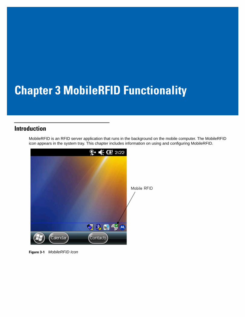
Chapter 3 MobileRFID Functionality
IntroductionMobileRFID is an RFID server application that runs in the background on the mobile computer. The MobileRFID icon appears in the system tray. This chapter includes information on using and configuring MobileRFID.
Figure 3-1 MobileRFID Icon
3 - 2 MC919Z Integrator Guide Supplement
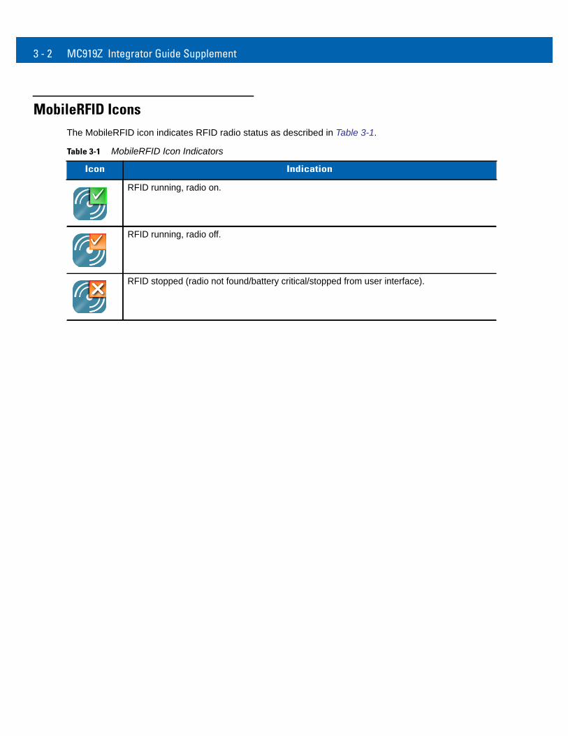
MobileRFID IconsThe MobileRFID icon indicates RFID radio status as described in Table 3-1.
Table 3-1 MobileRFID Icon Indicators
Icon Indication
RFID running, radio on.
RFID running, radio off.
RFID stopped (radio not found/battery critical/stopped from user interface).
MobileRFID Functionality 3 - 3
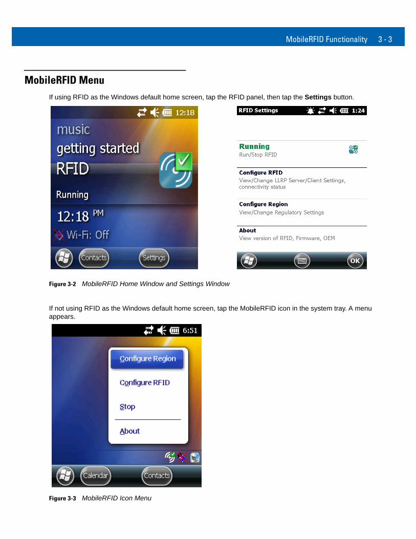
MobileRFID MenuIf using RFID as the Windows default home screen, tap the RFID panel, then tap the Settings button.
Figure 3-2 MobileRFID Home Window and Settings Window
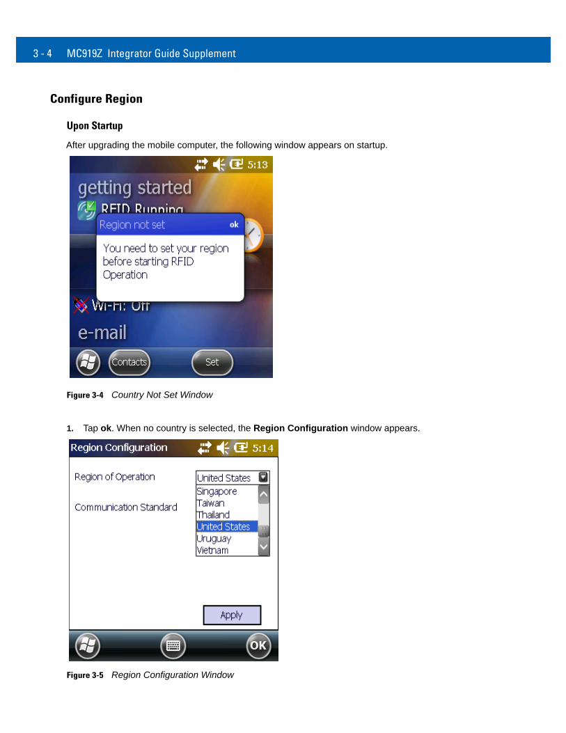
If not using RFID as the Windows default home screen, tap the MobileRFID icon in the system tray. A menu appears.
Figure 3-3 MobileRFID Icon Menu
3 - 4 MC919Z Integrator Guide Supplement
Configure Region
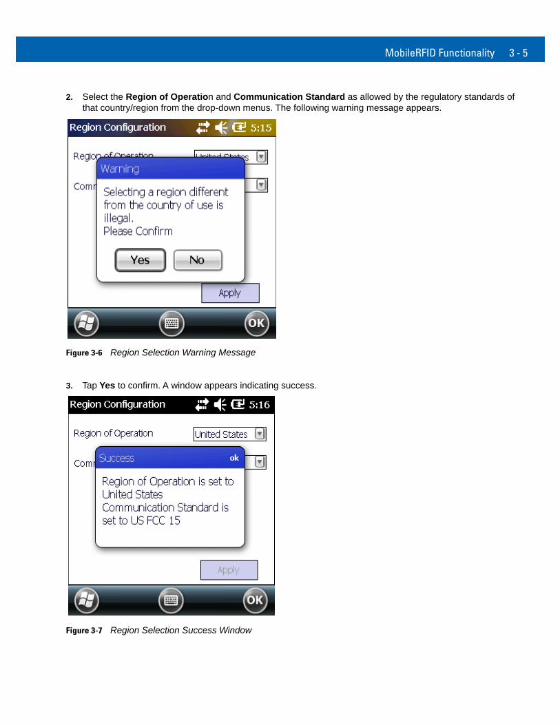
Upon Startup
After upgrading the mobile computer, the following window appears on startup.
Figure 3-4 Country Not Set Window
1. Tap ok. When no country is selected, the Region Configuration window appears.
Figure 3-5 Region Configuration Window
MobileRFID Functionality 3 - 5
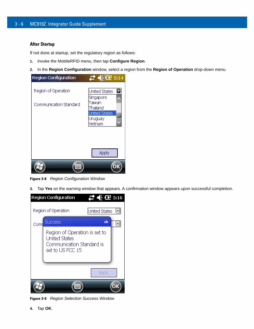
2. Select the Region of Operation and Communication Standard as allowed by the regulatory standards of that country/region from the drop-down menus. The following warning message appears.
Figure 3-6 Region Selection Warning Message
3. Tap Yes to confirm. A window appears indicating success.
Figure 3-7 Region Selection Success Window
3 - 6 MC919Z Integrator Guide Supplement
After Startup
If not done at startup, set the regulatory region as follows:
1. Invoke the MobileRFID menu, then tap Configure Region.
2. In the Region Configuration window, select a region from the Region of Operation drop-down menu.
Figure 3-8 Region Configuration Window
3. Tap Yes on the warning window that appears. A confirmation window appears upon successful completion.
Figure 3-9 Region Selection Success Window
4. Tap OK.
MobileRFID Functionality 3 - 7
Configure RFID
RFID is in Server Mode by default. To configure RFID to operate in Client Mode:
1. Invoke the MobileRFID menu, then tap Configure RFID.
Figure 3-10 RFID Configuration Window
2. Select the Client Mode check box.
3. In the LLRP Port field, enter the port number on which the server waits for the RFID client to communicate. The default is 5084.
4. In the Server IP field, enter the server IP for the remote host to which RFID communicates as a client.
5. Tap Apply.
6. Tap OK to close the window.
3 - 8 MC919Z Integrator Guide Supplement
Version Information
To view software version information for the RFID application, invoke the MobileRFID menu, then tap About.
Figure 3-11 About MobileRFID Window
This window displays the MobileRFID application version, radio library version, radio firmware version, and radio OEM data version.
NOTE The version information in Figure 3-11 may differ from the information on the actual mobile computer screen.
MobileRFID Functionality 3 - 9
Run/Stop RFID
To stop RFID service, tap Stop in MobileRFID menu.
Figure 3-12 RFID Stopped
To restart RFID, tap Run in MobileRFID menu.

3 - 10 MC919Z Integrator Guide Supplement

Chapter 4 RFID Sample Application
IntroductionThe RFID Application CS_RFID3Sample6.exe provides an overview of how the application works and assists application developers in developing custom applications.
The mobile computer can read, write, lock, kill, and program Gen2 tags. Each tag contains the EPC number (64 or 96 bits), CRC, and kill code. The mobile computer can also collect data by decoding in-range EPC Gen2 RFID tags.
Initiating the read command within the sample application causes the mobile computer to interrogate all RFID tags within the radio frequency (RF) field of view. The reader captures data from each new tag and adds it to the list box in the EPC ID window. Select Stop Read to stop interrogating tags.
4 - 2 MC919Z Integrator Guide Supplement
Launching the RFID Sample ApplicationSelect RFID Demo in the Start menu to start the RFID sample application.
Figure 4-1 RFID Demo Icon
Figure 4-2 RFID Sample Application Window
In the sample application window:
• Tap the Start Reading button to initiate the tag read. Tap Stop Reading to terminate tag reading.
• Use the Mem Bank drop-down to select a tag memory bank to read. The default memory bank is EPC (None). Other options are TID, Reserved, and User.
RFID Sample Application 4 - 3
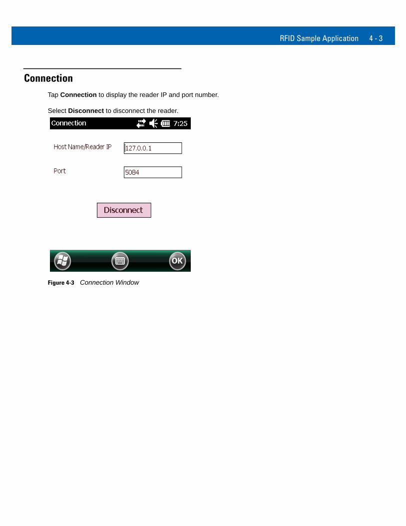
ConnectionTap Connection to display the reader IP and port number.
Select Disconnect to disconnect the reader.
Figure 4-3 Connection Window
4 - 4 MC919Z Integrator Guide Supplement
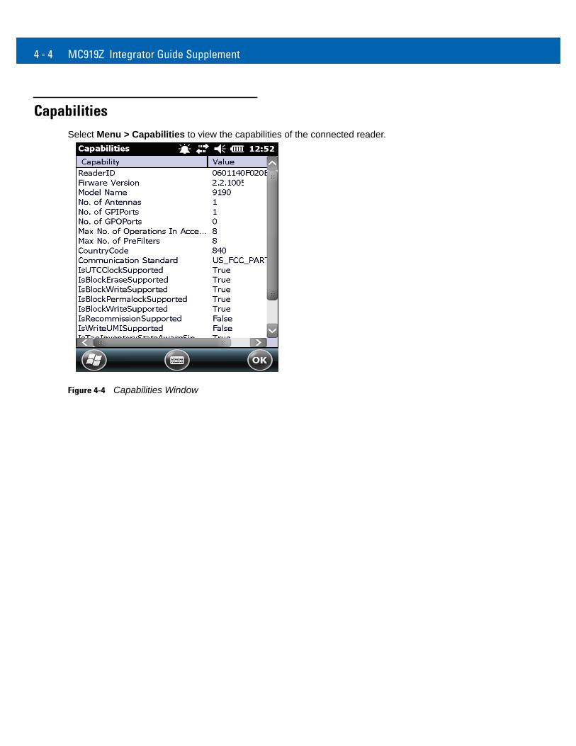
CapabilitiesSelect Menu > Capabilities to view the capabilities of the connected reader.
Figure 4-4 Capabilities Window
RFID Sample Application 4 - 5
Configuration Menu OptionsThe Configuration Menu includes the following options:
• Tag Storage Settings
• Antenna
• RF Mode
• Singulation
• Power On/Off Radio
• Reset to Factory Defaults
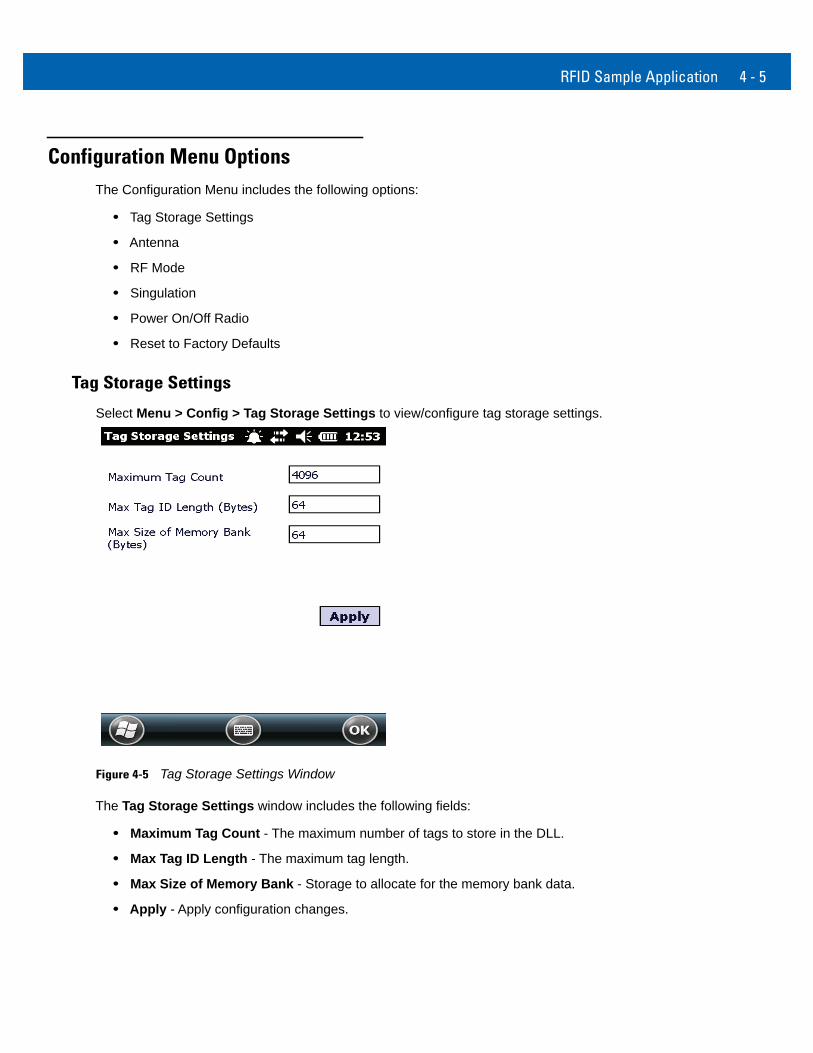
Tag Storage Settings
Select Menu > Config > Tag Storage Settings to view/configure tag storage settings.
Figure 4-5 Tag Storage Settings Window
The Tag Storage Settings window includes the following fields:
• Maximum Tag Count - The maximum number of tags to store in the DLL.
• Max Tag ID Length - The maximum tag length.
• Max Size of Memory Bank - Storage to allocate for the memory bank data.
• Apply - Apply configuration changes.
4 - 6 MC919Z Integrator Guide Supplement
Antenna
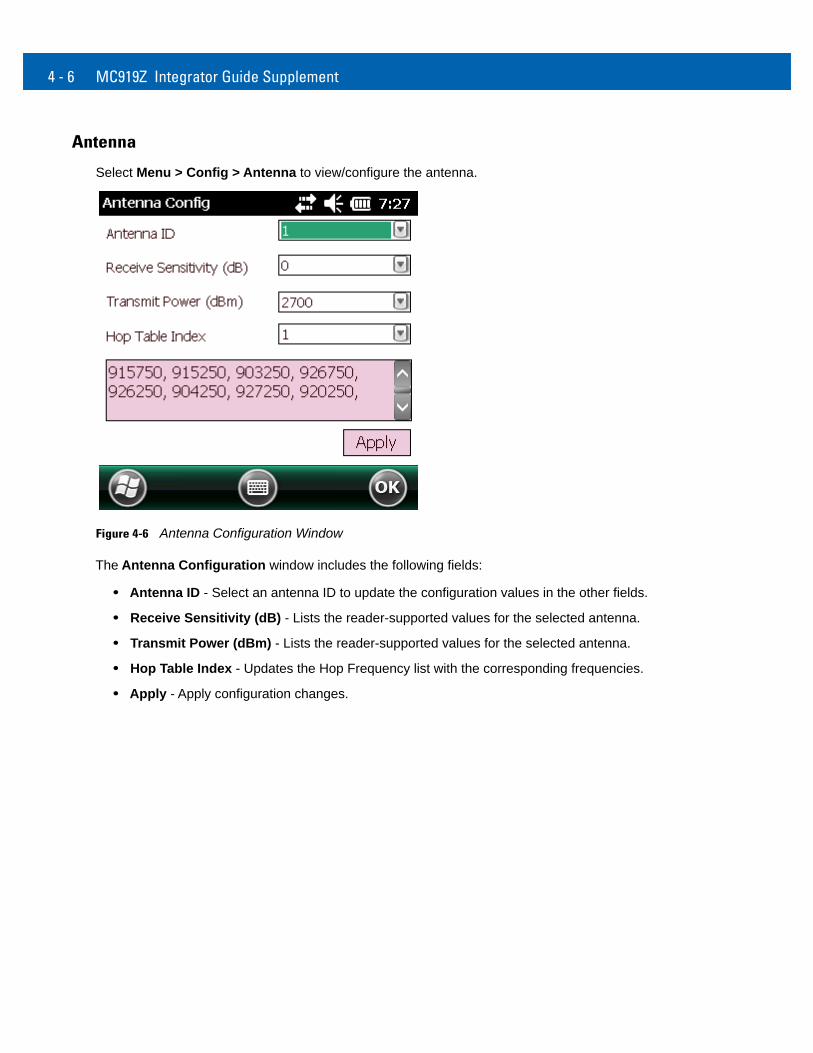
Select Menu > Config > Antenna to view/configure the antenna.
Figure 4-6 Antenna Configuration Window
The Antenna Configuration window includes the following fields:
• Antenna ID - Select an antenna ID to update the configuration values in the other fields.
• Receive Sensitivity (dB) - Lists the reader-supported values for the selected antenna.
• Transmit Power (dBm) - Lists the reader-supported values for the selected antenna.
• Hop Table Index - Updates the Hop Frequency list with the corresponding frequencies.
• Apply - Apply configuration changes.
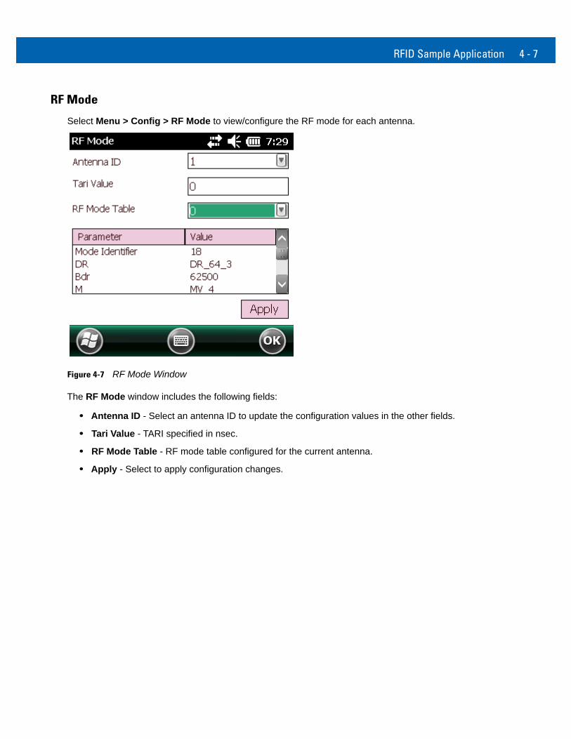
RFID Sample Application 4 - 7
RF Mode
Select Menu > Config > RF Mode to view/configure the RF mode for each antenna.
Figure 4-7 RF Mode Window
The RF Mode window includes the following fields:
• Antenna ID - Select an antenna ID to update the configuration values in the other fields.
• Tari Value - TARI specified in nsec.
• RF Mode Table - RF mode table configured for the current antenna.
• Apply - Select to apply configuration changes.
4 - 8 MC919Z Integrator Guide Supplement
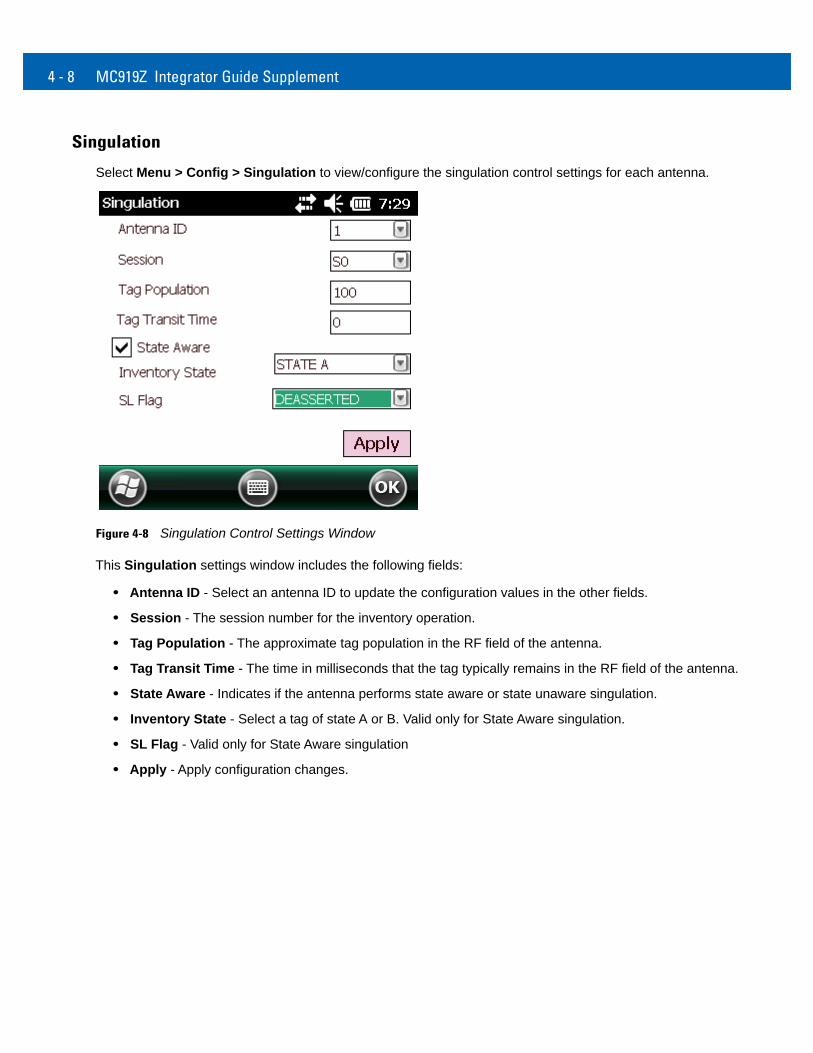
Singulation
Select Menu > Config > Singulation to view/configure the singulation control settings for each antenna.
Figure 4-8 Singulation Control Settings Window
This Singulation settings window includes the following fields:
• Antenna ID - Select an antenna ID to update the configuration values in the other fields.
• Session - The session number for the inventory operation.
• Tag Population - The approximate tag population in the RF field of the antenna.
• Tag Transit Time - The time in milliseconds that the tag typically remains in the RF field of the antenna.
• State Aware - Indicates if the antenna performs state aware or state unaware singulation.
• Inventory State - Select a tag of state A or B. Valid only for State Aware singulation.
• SL Flag - Valid only for State Aware singulation
• Apply - Apply configuration changes.
RFID Sample Application 4 - 9
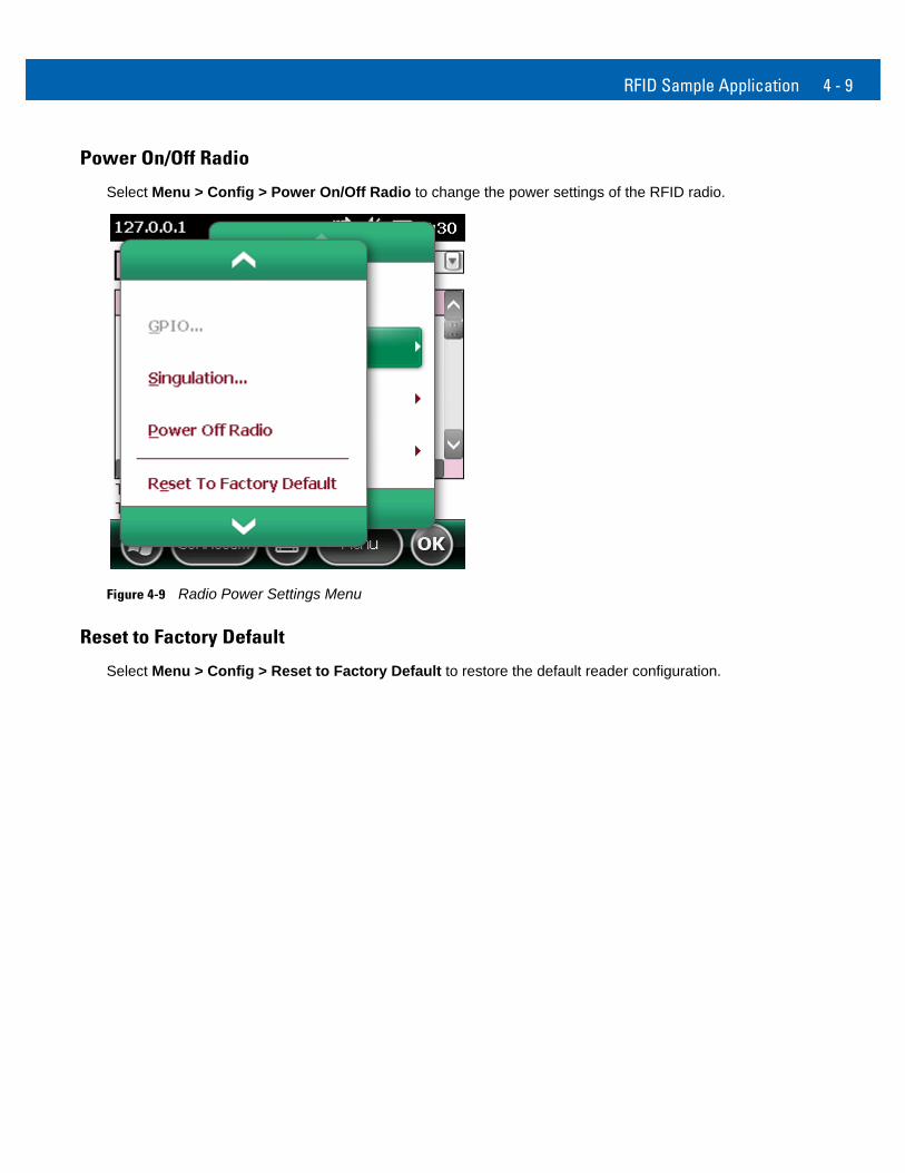
Power On/Off Radio
Select Menu > Config > Power On/Off Radio to change the power settings of the RFID radio.
Figure 4-9 Radio Power Settings Menu
Reset to Factory Default
Select Menu > Config > Reset to Factory Default to restore the default reader configuration.
4 - 10 MC919Z Integrator Guide Supplement
Operations Menu OptionsThe Operations Menu includes the following options:
• Antenna Info
• Filter
• Access
• Triggers
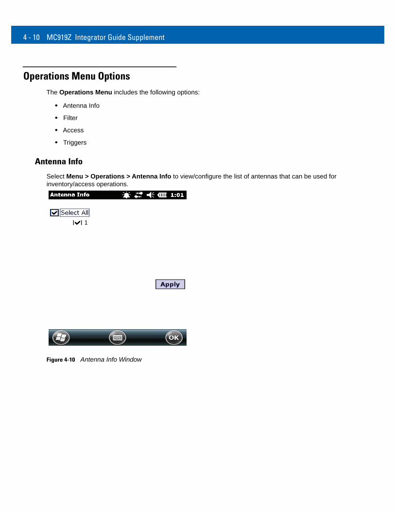
Antenna Info
Select Menu > Operations > Antenna Info to view/configure the list of antennas that can be used for inventory/access operations.
Figure 4-10 Antenna Info Window
RFID Sample Application 4 - 11
Filter
Select Menu > Operations > Filter to view/configure the following filters:
• Pre-Filter
• Post-Filter
• Access-Filter
Pre-Filter
Select Menu > Operations > Filter > Pre-Filter to view/configure pre-filters.
Figure 4-11 PreFilter Window
This Pre-Filter window includes the following fields:
• Antenna ID - Select an antenna ID to update the configuration values in the other fields.
• Memory Bank - Memory bank on which the filter is applied.
• Offset - The first (msb) bit location of the specified memory bank against which to compare the tag mask.
• Tag Pattern - The pattern against which to compare the specified memory bank.
• Filter Action - Select the required filter action. For more information, refer to the Gen2 specification available at http://www.epcglobalinc.org/standards/.
4 - 12 MC919Z Integrator Guide Supplement
Post-Filter
Select Menu > Operations > Filter > Post-Filter to view/configure post-filters.
Figure 4-12 Post-Filter Window
This Post-Filter window includes the following fields:
• Memory Bank - Memory bank on which the filter is applied.
• Offset - The first (msb) bit location of the specified memory bank against which to compare the tag mask.
• Tag Pattern - The pattern against which to compare the specified memory bank.
• Tag Mask - The bit mask to facilitate bit wise filtering.
• Match Pattern - Select the tag pattern to match (A, B, both, or neither).
RFID Sample Application 4 - 13
Access-Filter
Select Menu > Operations > Filter > Access-Filter to view/configure the access-filters.
Figure 4-13 Access-Filter Window
This Access-Filter window includes the following fields:
• Memory Bank - Memory bank on which the filter is applied.
• Offset - The first (msb) bit location of the specified memory bank against which to compare the tag mask.
• Tag Pattern - The pattern against which to compare the specified memory bank.
• Tag Mask - The bit mask to facilitate bit wise filtering.
• Match Pattern - Select the tag pattern to match (A, B, both, or neither).
4 - 14 MC919Z Integrator Guide Supplement
Access
Select Menu > Operations > Access to perform the following access operations.
Figure 4-14 Access Menu
The Access menu includes the following options:
• Read
• Write
• Lock
• Kill
• Block Write
• Block Erase
RFID Sample Application 4 - 15
To perform an access option on a single tag, right-click the tag in the list of read tags on the main window to invoke the tag’s context menu.
Figure 4-15 Tag Context Menu
Access Operation Windows
The Access Operation windows include the following fields. Set options as required in the various parameter windows. Not all windows include all options.
• Tag ID - The name of the selected tag.
• Password - Set a password before performing any access operation (except Kill).
• Memory Bank - Select the memory bank (Reserved, EPC, TID, User)
• Offset - Offset of the first word to read from the selected memory bank.
• Length - Tag/data length.
• Write Data - The data to write to the selected tag (Write window only).
• Lock Privilege - Access options for the selected tag (Write window only): • None - Can not change the lock privilege of the particular memory bank. • Read_Write - User can read and write to the tag. • Perma_Lock - Permanent lock. • Perma_Unlock - Permanent unlock. • Unlock - User can unlock the tag for writing.
4 - 16 MC919Z Integrator Guide Supplement
Figure 4-16 Read Access Operation Window
Figure 4-17 Write / Block-Write Access Operation Window
RFID Sample Application 4 - 17
Figure 4-18 Lock Access Operation Window
Figure 4-19 Kill Access Operation Window
4 - 18 MC919Z Integrator Guide Supplement
Figure 4-20 Block Erase Access Operation Window
RFID Sample Application 4 - 19
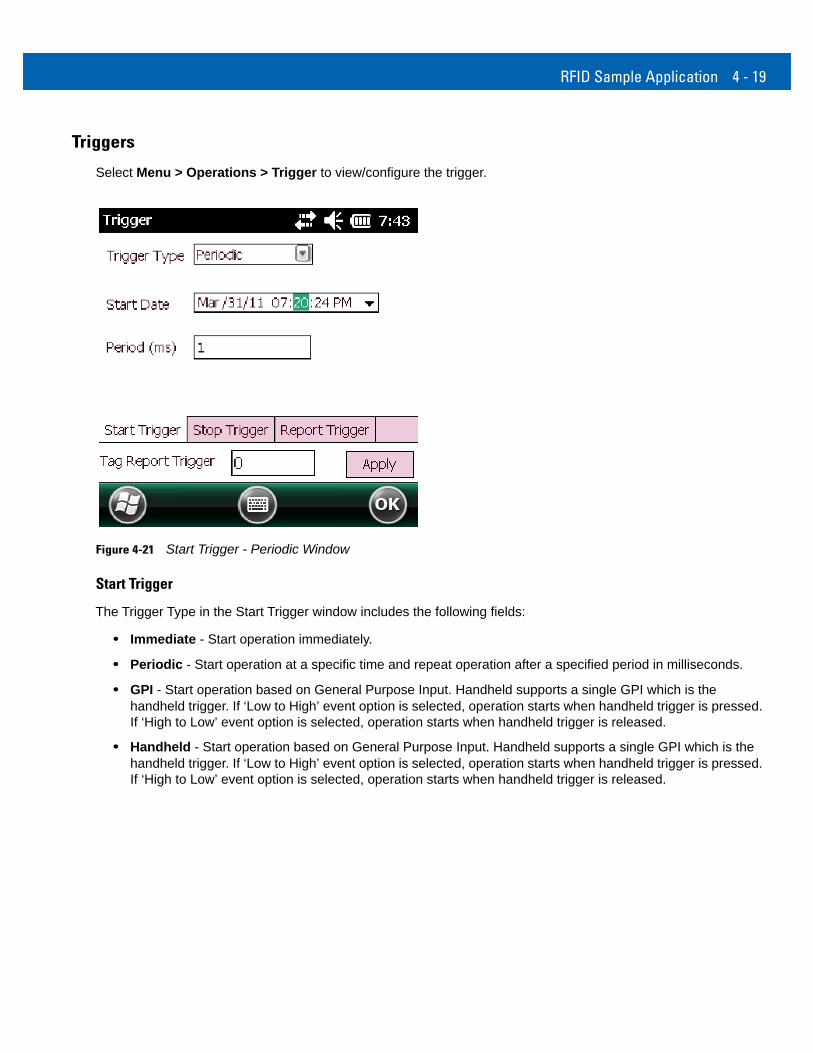
Triggers
Select Menu > Operations > Trigger to view/configure the trigger.
Figure 4-21 Start Trigger - Periodic Window
Start Trigger
The Trigger Type in the Start Trigger window includes the following fields:
• Immediate - Start operation immediately.
• Periodic - Start operation at a specific time and repeat operation after a specified period in milliseconds.
• GPI - Start operation based on General Purpose Input. Handheld supports a single GPI which is the handheld trigger. If ‘Low to High’ event option is selected, operation starts when handheld trigger is pressed. If ‘High to Low’ event option is selected, operation starts when handheld trigger is released.
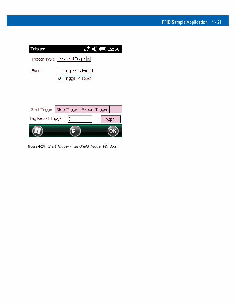
• Handheld - Start operation based on General Purpose Input. Handheld supports a single GPI which is the handheld trigger. If ‘Low to High’ event option is selected, operation starts when handheld trigger is pressed. If ‘High to Low’ event option is selected, operation starts when handheld trigger is released.
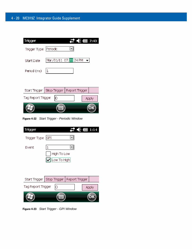
4 - 20 MC919Z Integrator Guide Supplement
Figure 4-22 Start Trigger - Periodic Window
Figure 4-23 Start Trigger - GPI Window
RFID Sample Application 4 - 21
Figure 4-24 Start Trigger - Handheld Trigger Window
4 - 22 MC919Z Integrator Guide Supplement
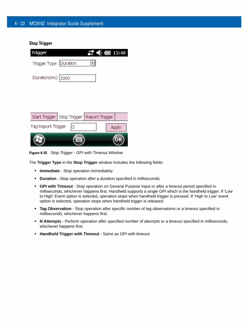
Stop Trigger
Figure 4-25 Stop Trigger - GPI with Timeout Window
The Trigger Type in the Stop Trigger window includes the following fields:
• Immediate - Stop operation immediately.
• Duration - Stop operation after a duration specified in milliseconds.
• GPI with Timeout - Stop operation on General Purpose Input or after a timeout period specified in milliseconds, whichever happens first. Handheld supports a single GPI which is the handheld trigger. If ‘Low to High’ Event option is selected, operation stops when handheld trigger is pressed. If ‘High to Low’ event option is selected, operation stops when handheld trigger is released.
• Tag Observation - Stop operation after specific number of tag observations or a timeout specified in milliseconds, whichever happens first.
• N Attempts - Perform operation after specified number of attempts or a timeout specified in milliseconds, whichever happens first.
• Handheld Trigger with Timeout - Same as GPI with timeout
RFID Sample Application 4 - 23
Figure 4-26 Stop Trigger - GPI with Timeout
Figure 4-27 Stop Trigger - Tag Observation with Timeout Window
4 - 24 MC919Z Integrator Guide Supplement
Figure 4-28 Stop Trigger - N Attempts with Timeout Window
Figure 4-29 Stop Trigger - Handheld Trigger with Timeout Window
RFID Sample Application 4 - 25
Report Trigger
Figure 4-30 Report Trigger Window
Report settings are applicable when tag options are checked in the main window of the demo application. The following event generations are controlled by criteria settings in Report Trigger.
The events associated with a tag are as follows:
• New Tag - Tag seen by the reader for the first time.
• Tag Invisible - Tag which was in the field of view of the reader is now not seen.
• Tag Back to Visibility - An invisible tag has come back in field of view of reader.
Criteria selections are as follows:
• Never - Corresponding event is never reported.
• Immediate - Corresponding event is immediately reported when it happens.
• Moderated - Event is generated after monitoring for sustained occurrence of the event for a period of time specified in milliseconds.
4 - 26 MC919Z Integrator Guide Supplement
Management Menu OptionsManagement options are not applicable for handheld readers.
Help MenuSelect Menu > Help to display the version information. The version numbers displayed in this window are examples. Actual version numbers are based on the versions of the files on the device.
Figure 4-31 Help Window
ExitSelect Menu > Exit to exit the RFID sample application.
Chapter 5 Tag Locator
IntroductionUse Tag Locator to detect the location of a tag. By providing the TagID of an item, this application can find the relative position of the tag with respect to the mobile computer. Move the mobile computer back and forth to obtain the location of the tag as indicated by the beep frequency and a vertical progress bar showing the relative position of the tag.
The Tag Locator application requires the following components/DLLs on the device:
• RFIDAPI32.dll (Version 5.1.15 or higher)
• Symbol.RFID3.Device.dll (Assembly version 5.2.0.8, File version 1.2.0.0 or higher)
• Symbol.Audio.dll
• Symbol.dll
• Symbol.Notification.dll
• Symbol.StandardForms.dll
5 - 2 MC919Z Integrator Guide Supplement
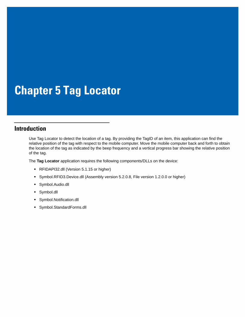
Using Tag LocatorTo use the Tag Locator application:
1. Tap Tag Locator in the Application folder on the mobile computer to open the Tag Locator application.
Figure 5-1 Tag Locator
2. Enter the tag ID in one of three ways:
• Type the tag ID in the TagID text box, then select Locate or press and hold the trigger.
• Perform a search operation by selecting the Search Tags button or by pressing and holding the trigger.
• Select the Import Tags button to import a list of saved tags from a .csv file. See Locating Tags Using a .csv File on page 5-3.
Tag Locator 5 - 3
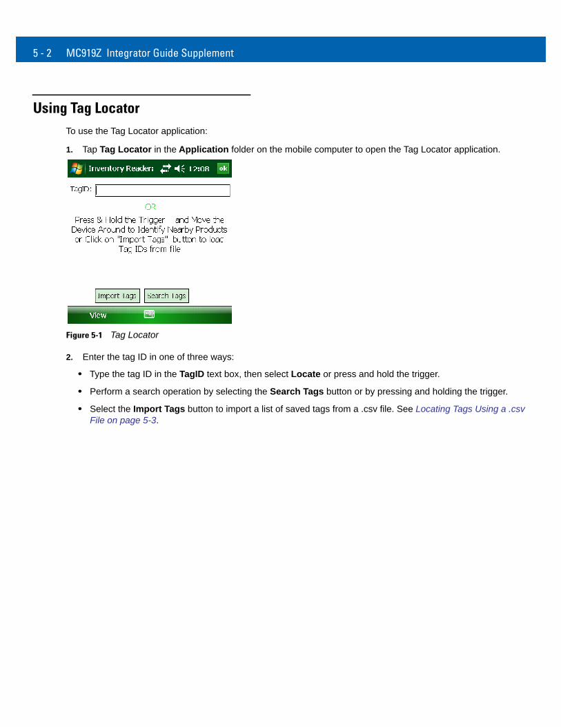
Locating Tags Using a .csv File1. Select the Import Tags button to import a list of saved tags from a .csv file. The following window appears.
Figure 5-2 Opening a .csv File
2. Select the desired .csv file to import the tags to the list.
Figure 5-3 Tag List
3. Select a tag from the list to search.
5 - 4 MC919Z Integrator Guide Supplement
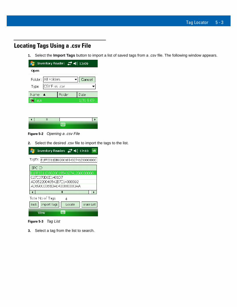
4. Select the Locate button or press and hold the trigger. Move the mobile computer in all directions to get the relative position of the tag, indicated by a beep, the vertical progress bar, or both.
Figure 5-4 Tag Search
Use the Options menu to turn the beeper on and off and to display data in ASCII or hexadecimal format.
Figure 5-5 Options Menu
Chapter 6 Troubleshooting
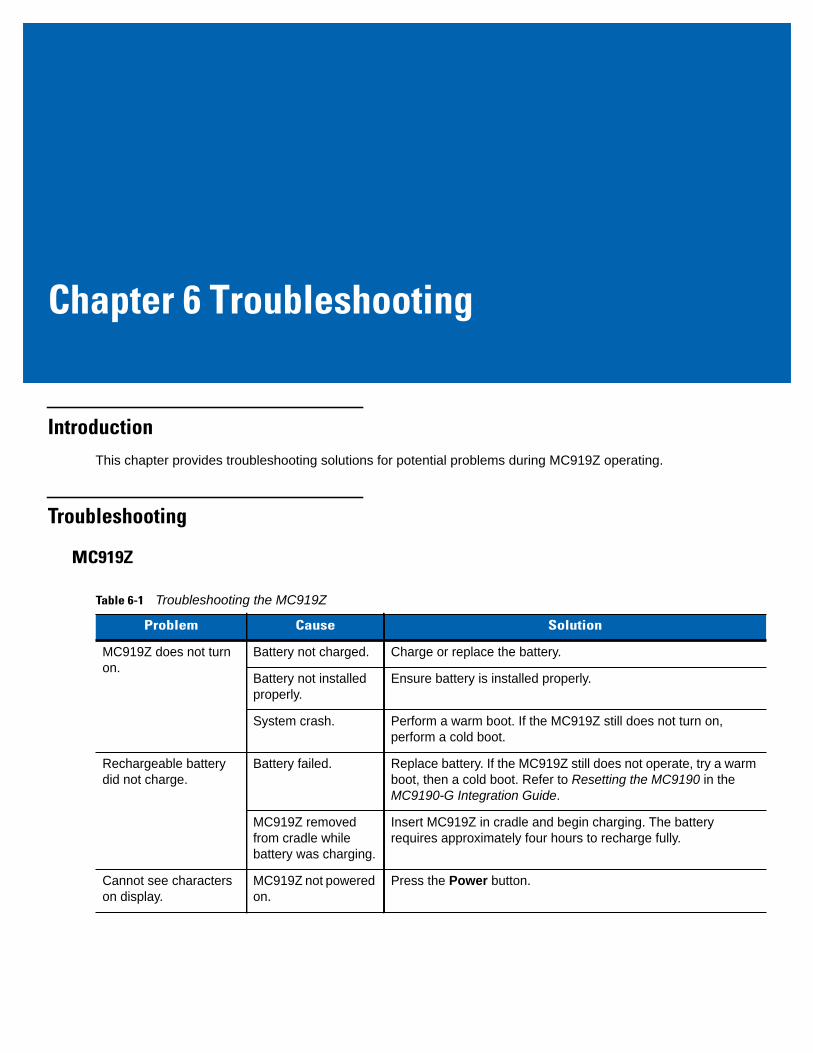
IntroductionThis chapter provides troubleshooting solutions for potential problems during MC919Z operating.
Troubleshooting
MC919Z
Table 6-1 Troubleshooting the MC919Z
Problem Cause Solution
MC919Z does not turn on.
Battery not charged. Charge or replace the battery.
Battery not installed properly.
Ensure battery is installed properly.
System crash. Perform a warm boot. If the MC919Z still does not turn on, perform a cold boot.
Rechargeable battery did not charge.
Battery failed. Replace battery. If the MC919Z still does not operate, try a warm boot, then a cold boot. Refer to Resetting the MC9190 in the MC9190-G Integration Guide.
MC919Z removed from cradle while battery was charging.
Insert MC919Z in cradle and begin charging. The battery requires approximately four hours to recharge fully.
Cannot see characters on display.
MC919Z not powered on.
Press the Power button.
6 - 2 MC919Z Integrator Guide Supplement
During data communication, no data was transmitted, or transmitted data was incomplete.
MC919Z removed from cradle or unplugged from host computer during communication.
Replace the MC919Z in the cradle, or reattach the Synchronization cable and re-transmit.
Incorrect cable configuration.
See the System Administrator.
Communication software was incorrectly installed or configured.
Perform setup. Refer to refer to the MC9190-G Integration Guide for details.
Ensure that Microsoft ActiveSync 4.5 or greater is installed on the host computer.
No sound is audible. Volume setting is low or turned off.
Turn on or increase volume.
MC919Z turns itself off. MC919Z is inactive. The MC919Z turns off after a period of inactivity. If the MC919Z is running on battery power, this period can be set to 30 sec., 1, 2, 3, 4, 5 or 6 minutes. If the MC919Z is running on external power, this period can be set to 1, 2, 3, 5, 10, 15 and 30 minutes.For Windows Mobile 6.5 devices, Check the power settings by tapping Start > Settings > System > Power > Advanced. Change the setting if you need a longer delay before the automatic shutoff feature activates.
Battery is depleted. Replace the battery.
Battery is not inserted properly.
Insert the battery properly.
Tapping the window buttons or icons does not activate the corresponding feature.
LCD screen not aligned correctly.
Re-calibrate the screen.
The system is hung. Warm boot the system. To perform a warm boot (refer to Resetting the MC9190-G in the MC9190-G Integration Guide).
A message appears stating that the MC919Z memory is full.
Too many files stored on the MC919Z.
Delete unused memos and records. You can save these records on the host computer.
Too many applications installed on the MC919Z.
If you have installed additional applications on the MC919Z, remove them to recover memory.For Windows Mobile 6.5 devices, tap Start > Settings > System > Remove Programs.Select the unused program and tap Remove.
Table 6-1 Troubleshooting the MC919Z (Continued)
Problem Cause Solution
Troubleshooting 6 - 3
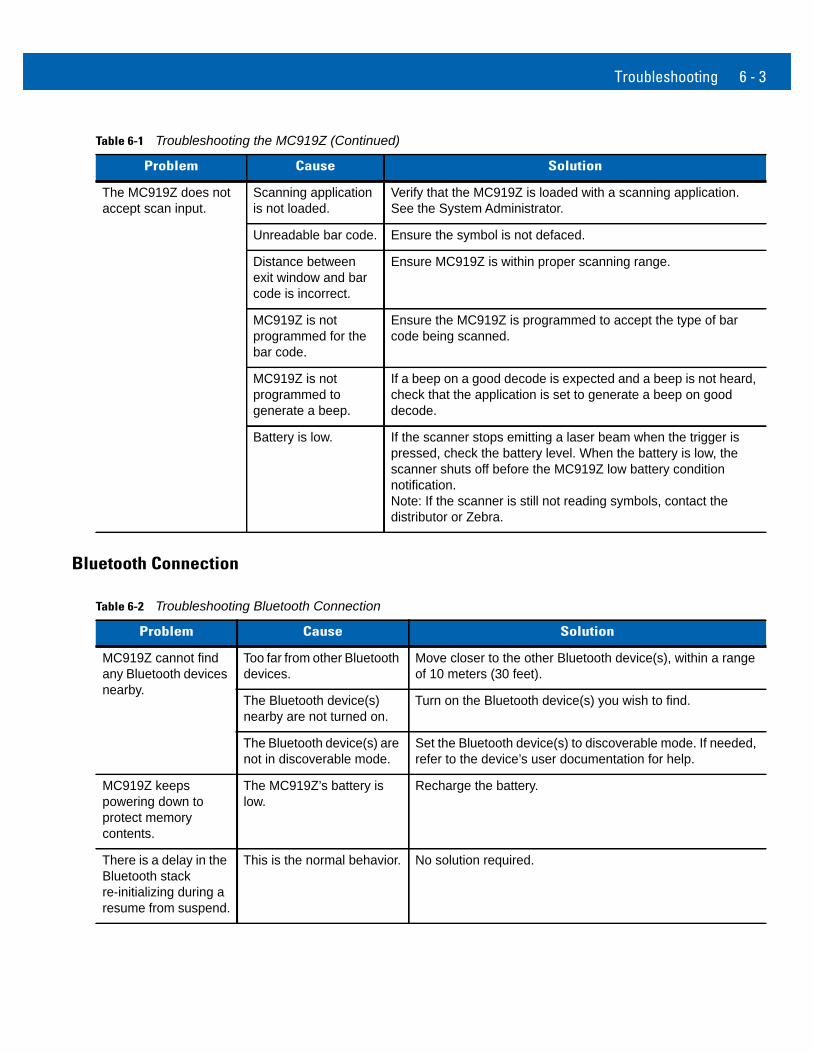
Bluetooth Connection
The MC919Z does not accept scan input.
Scanning application is not loaded.
Verify that the MC919Z is loaded with a scanning application. See the System Administrator.
Unreadable bar code. Ensure the symbol is not defaced.
Distance between exit window and bar code is incorrect.
Ensure MC919Z is within proper scanning range.
MC919Z is not programmed for the bar code.
Ensure the MC919Z is programmed to accept the type of bar code being scanned.
MC919Z is not programmed to generate a beep.
If a beep on a good decode is expected and a beep is not heard, check that the application is set to generate a beep on good decode.
Battery is low. If the scanner stops emitting a laser beam when the trigger is pressed, check the battery level. When the battery is low, the scanner shuts off before the MC919Z low battery condition notification. Note: If the scanner is still not reading symbols, contact the distributor or Zebra.
Table 6-1 Troubleshooting the MC919Z (Continued)
Problem Cause Solution
Table 6-2 Troubleshooting Bluetooth Connection
Problem Cause Solution
MC919Z cannot find any Bluetooth devices nearby.
Too far from other Bluetooth devices.
Move closer to the other Bluetooth device(s), within a range of 10 meters (30 feet).
The Bluetooth device(s) nearby are not turned on.
Turn on the Bluetooth device(s) you wish to find.
The Bluetooth device(s) are not in discoverable mode.
Set the Bluetooth device(s) to discoverable mode. If needed, refer to the device’s user documentation for help.
MC919Z keeps powering down to protect memory contents.
The MC919Z’s battery is low.
Recharge the battery.
There is a delay in the Bluetooth stack re-initializing during a resume from suspend.
This is the normal behavior. No solution required.
6 - 4 MC919Z Integrator Guide Supplement
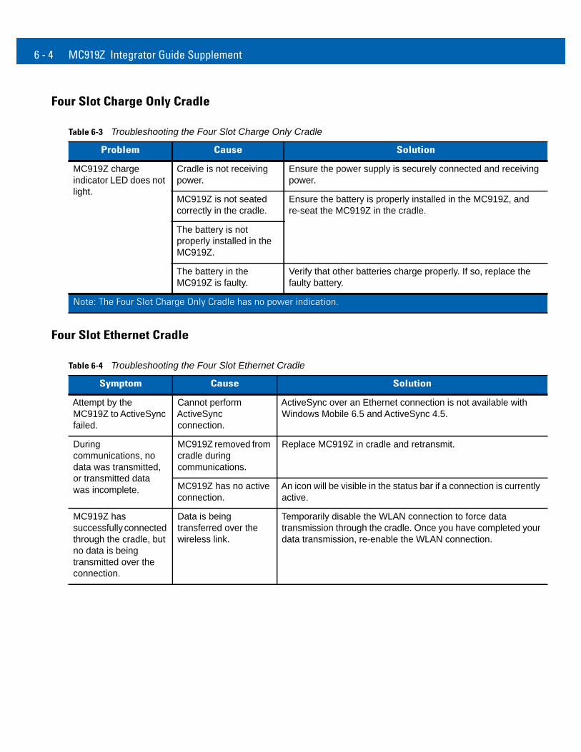
Four Slot Charge Only Cradle
Four Slot Ethernet Cradle
Table 6-3 Troubleshooting the Four Slot Charge Only Cradle
Problem Cause Solution
MC919Z charge indicator LED does not light.
Cradle is not receiving power.
Ensure the power supply is securely connected and receiving power.
MC919Z is not seated correctly in the cradle.
Ensure the battery is properly installed in the MC919Z, and re-seat the MC919Z in the cradle.
The battery is not properly installed in the MC919Z.
The battery in the MC919Z is faulty.
Verify that other batteries charge properly. If so, replace the faulty battery.
Note: The Four Slot Charge Only Cradle has no power indication.
Table 6-4 Troubleshooting the Four Slot Ethernet Cradle
Symptom Cause Solution
Attempt by the MC919Z to ActiveSync failed.
Cannot perform ActiveSync connection.
ActiveSync over an Ethernet connection is not available with Windows Mobile 6.5 and ActiveSync 4.5.
During communications, no data was transmitted, or transmitted data was incomplete.
MC919Z removed from cradle during communications.
Replace MC919Z in cradle and retransmit.
MC919Z has no active connection.
An icon will be visible in the status bar if a connection is currently active.
MC919Z has successfully connected through the cradle, but no data is being transmitted over the connection.
Data is being transferred over the wireless link.
Temporarily disable the WLAN connection to force data transmission through the cradle. Once you have completed your data transmission, re-enable the WLAN connection.
Troubleshooting 6 - 5
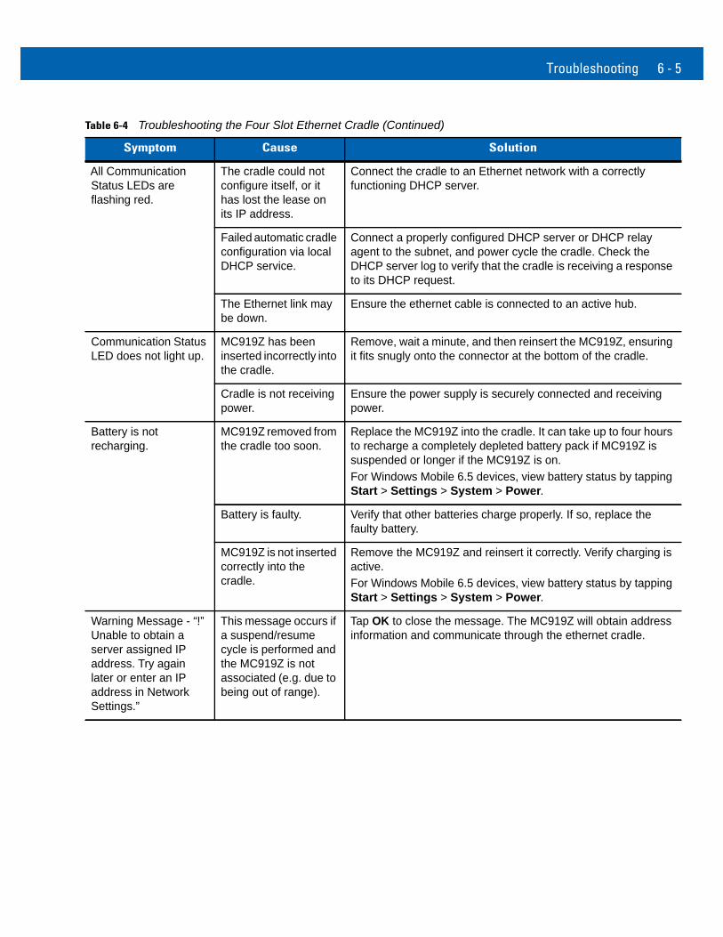
All Communication Status LEDs are flashing red.
The cradle could not configure itself, or it has lost the lease on its IP address.
Connect the cradle to an Ethernet network with a correctly functioning DHCP server.
Failed automatic cradle configuration via local DHCP service.
Connect a properly configured DHCP server or DHCP relay agent to the subnet, and power cycle the cradle. Check the DHCP server log to verify that the cradle is receiving a response to its DHCP request.
The Ethernet link may be down.
Ensure the ethernet cable is connected to an active hub.
Communication Status LED does not light up.
MC919Z has been inserted incorrectly into the cradle.
Remove, wait a minute, and then reinsert the MC919Z, ensuring it fits snugly onto the connector at the bottom of the cradle.
Cradle is not receiving power.
Ensure the power supply is securely connected and receiving power.
Battery is not recharging.
MC919Z removed from the cradle too soon.
Replace the MC919Z into the cradle. It can take up to four hours to recharge a completely depleted battery pack if MC919Z is suspended or longer if the MC919Z is on. For Windows Mobile 6.5 devices, view battery status by tapping Start > Settings > System > Power.
Battery is faulty. Verify that other batteries charge properly. If so, replace the faulty battery.
MC919Z is not inserted correctly into the cradle.
Remove the MC919Z and reinsert it correctly. Verify charging is active. For Windows Mobile 6.5 devices, view battery status by tapping Start > Settings > System > Power.
Warning Message - “!” Unable to obtain a server assigned IP address. Try again later or enter an IP address in Network Settings.”
This message occurs if a suspend/resume cycle is performed and the MC919Z is not associated (e.g. due to being out of range).
Tap OK to close the message. The MC919Z will obtain address information and communicate through the ethernet cradle.
Table 6-4 Troubleshooting the Four Slot Ethernet Cradle (Continued)
Symptom Cause Solution
6 - 6 MC919Z Integrator Guide Supplement
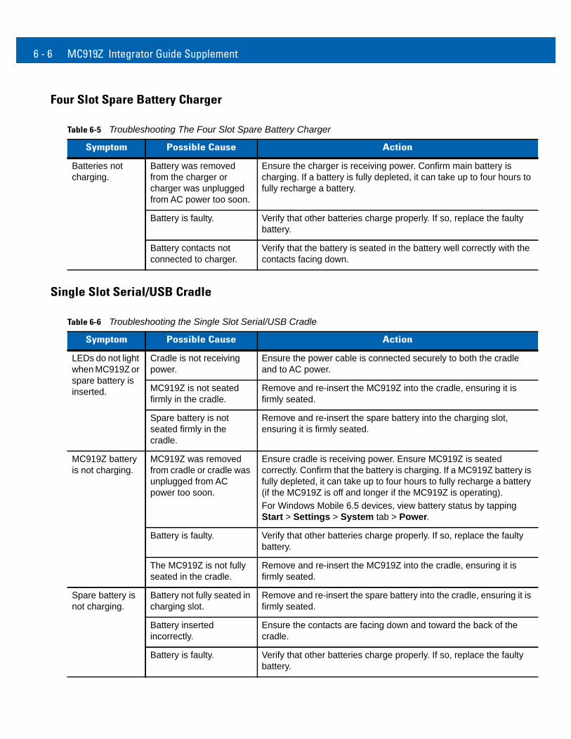
Four Slot Spare Battery Charger
Single Slot Serial/USB Cradle
Table 6-5 Troubleshooting The Four Slot Spare Battery Charger
Symptom Possible Cause Action
Batteries not charging.
Battery was removed from the charger or charger was unplugged from AC power too soon.
Ensure the charger is receiving power. Confirm main battery is charging. If a battery is fully depleted, it can take up to four hours to fully recharge a battery.
Battery is faulty. Verify that other batteries charge properly. If so, replace the faulty battery.
Battery contacts not connected to charger.
Verify that the battery is seated in the battery well correctly with the contacts facing down.
Table 6-6 Troubleshooting the Single Slot Serial/USB Cradle
Symptom Possible Cause Action
LEDs do not light when MC919Z or spare battery is inserted.
Cradle is not receiving power.
Ensure the power cable is connected securely to both the cradle and to AC power.
MC919Z is not seated firmly in the cradle.
Remove and re-insert the MC919Z into the cradle, ensuring it is firmly seated.
Spare battery is not seated firmly in the cradle.
Remove and re-insert the spare battery into the charging slot, ensuring it is firmly seated.
MC919Z battery is not charging.
MC919Z was removed from cradle or cradle was unplugged from AC power too soon.
Ensure cradle is receiving power. Ensure MC919Z is seated correctly. Confirm that the battery is charging. If a MC919Z battery is fully depleted, it can take up to four hours to fully recharge a battery (if the MC919Z is off and longer if the MC919Z is operating).For Windows Mobile 6.5 devices, view battery status by tapping Start > Settings > System tab > Power.
Battery is faulty. Verify that other batteries charge properly. If so, replace the faulty battery.
The MC919Z is not fully seated in the cradle.
Remove and re-insert the MC919Z into the cradle, ensuring it is firmly seated.
Spare battery is not charging.
Battery not fully seated in charging slot.
Remove and re-insert the spare battery into the cradle, ensuring it is firmly seated.
Battery inserted incorrectly.
Ensure the contacts are facing down and toward the back of the cradle.
Battery is faulty. Verify that other batteries charge properly. If so, replace the faulty battery.
Troubleshooting 6 - 7
Cable Adapter Module
During data communications, no data was transmitted, or transmitted data was incomplete.
MC919Z removed from cradle during communications.
Replace MC919Z in cradle and retransmit.
Incorrect cable configuration.
See the System Administrator.
Communications software is not installed or configured properly.
Perform setup as described in the Accessories section of the MC9190-G Integration Guide.
Ensure that Microsoft ActiveSync 4.5 or greater is installed on the host computer.
Table 6-6 Troubleshooting the Single Slot Serial/USB Cradle (Continued)
Symptom Possible Cause Action
Table 6-7 Troubleshooting The Cable Adapter Module
Symptom Possible Cause Action
MC919Z battery is not charging.
MC919Z was removed from CAM or CAM was unplugged from AC power too soon.
Ensure CAM is receiving power. Ensure MC919Z is attached correctly. Confirm that the battery is charging. If a MC919Z battery is fully depleted, it can take up to four hours to fully recharge a battery (if the MC919Z is off and longer if the MC919Z is operating).For Windows Mobile 6.5 devices, view battery status by tapping Start > Settings > System > Power.
Battery is faulty. Verify that other batteries charge properly. If so, replace the faulty battery.
The MC919Z is not fully attached to the CAM.
Detach and re-attach the CAM to the MC919Z, ensuring it is firmly connected.
During data communications, no data was transmitted, or transmitted data was incomplete.
MC919Z detached from CAM during communications.
Re-attach MC919Z to CAM and retransmit.
Incorrect cable configuration.
See the System Administrator.
Communications software is not installed or configured properly.
Perform setup as described in the Accessories section of the MC9190-G Integration Guide.
6 - 8 MC919Z Integrator Guide Supplement
Magnetic Stripe Reader
Table 6-8 Troubleshooting the Magnetic Stripe Reader
Symptom Possible Cause Action
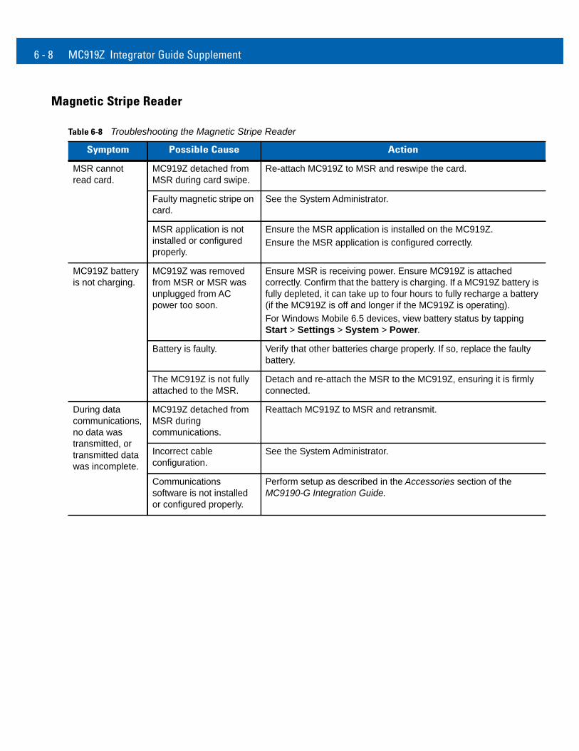
MSR cannot read card.
MC919Z detached from MSR during card swipe.
Re-attach MC919Z to MSR and reswipe the card.
Faulty magnetic stripe on card.
See the System Administrator.
MSR application is not installed or configured properly.
Ensure the MSR application is installed on the MC919Z. Ensure the MSR application is configured correctly.
MC919Z battery is not charging.
MC919Z was removed from MSR or MSR was unplugged from AC power too soon.
Ensure MSR is receiving power. Ensure MC919Z is attached correctly. Confirm that the battery is charging. If a MC919Z battery is fully depleted, it can take up to four hours to fully recharge a battery (if the MC919Z is off and longer if the MC919Z is operating).For Windows Mobile 6.5 devices, view battery status by tapping Start > Settings > System > Power.
Battery is faulty. Verify that other batteries charge properly. If so, replace the faulty battery.
The MC919Z is not fully attached to the MSR.
Detach and re-attach the MSR to the MC919Z, ensuring it is firmly connected.
During data communications, no data was transmitted, or transmitted data was incomplete.
MC919Z detached from MSR during communications.
Reattach MC919Z to MSR and retransmit.
Incorrect cable configuration.
See the System Administrator.
Communications software is not installed or configured properly.
Perform setup as described in the Accessories section of the MC9190-G Integration Guide.
Troubleshooting 6 - 9
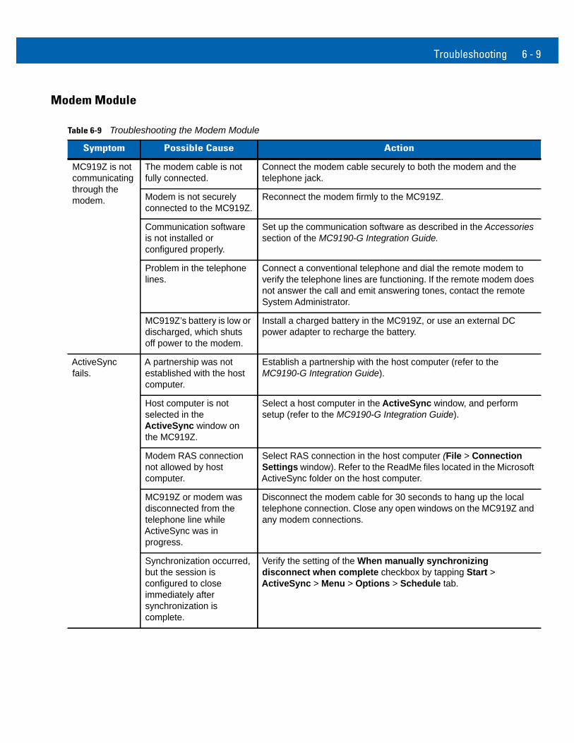
Modem Module
Table 6-9 Troubleshooting the Modem Module
Symptom Possible Cause Action
MC919Z is not communicating through the modem.
The modem cable is not fully connected.
Connect the modem cable securely to both the modem and the telephone jack.
Modem is not securely connected to the MC919Z.
Reconnect the modem firmly to the MC919Z.
Communication software is not installed or configured properly.
Set up the communication software as described in the Accessories section of the MC9190-G Integration Guide.
Problem in the telephone lines.
Connect a conventional telephone and dial the remote modem to verify the telephone lines are functioning. If the remote modem does not answer the call and emit answering tones, contact the remote System Administrator.
MC919Z’s battery is low or discharged, which shuts off power to the modem.
Install a charged battery in the MC919Z, or use an external DC power adapter to recharge the battery.
ActiveSync fails.
A partnership was not established with the host computer.
Establish a partnership with the host computer (refer to the MC9190-G Integration Guide).
Host computer is not selected in the ActiveSync window on the MC919Z.
Select a host computer in the ActiveSync window, and perform setup (refer to the MC9190-G Integration Guide).
Modem RAS connection not allowed by host computer.
Select RAS connection in the host computer (File > Connection Settings window). Refer to the ReadMe files located in the Microsoft ActiveSync folder on the host computer.
MC919Z or modem was disconnected from the telephone line while ActiveSync was in progress.
Disconnect the modem cable for 30 seconds to hang up the local telephone connection. Close any open windows on the MC919Z and any modem connections.
Synchronization occurred, but the session is configured to close immediately after synchronization is complete.
Verify the setting of the When manually synchronizing disconnect when complete checkbox by tapping Start > ActiveSync > Menu > Options > Schedule tab.
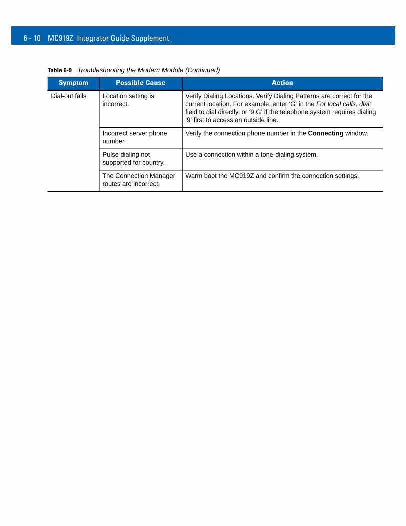
6 - 10 MC919Z Integrator Guide Supplement
Dial-out fails Location setting is incorrect.
Verify Dialing Locations. Verify Dialing Patterns are correct for the current location. For example, enter ‘G’ in the For local calls, dial: field to dial directly, or ‘9,G’ if the telephone system requires dialing ‘9’ first to access an outside line.
Incorrect server phone number.
Verify the connection phone number in the Connecting window.
Pulse dialing not supported for country.
Use a connection within a tone-dialing system.
The Connection Manager routes are incorrect.
Warm boot the MC919Z and confirm the connection settings.
Table 6-9 Troubleshooting the Modem Module (Continued)
Symptom Possible Cause Action

Appendix A Technical Specifications
MC919Z SpecificationsThe following table summarizes the MC919Z’s technical specifications.
Table A-1 Technical Specifications
Item Description
Physical and Environmental Characteristics
Dimensions 10.83 in. L x 4.7 in. W x 7.6 in. H27.50 cm L x 11.95 cm H x 19.3 cm H
Weight (includes battery, scanner and radio)
Lorax: 1077 g (38 oz.)SE4500 or SE960: 974 g (34.4 oz.)
Keyboard 28-key; 43-key; 53-key
Display 3.7” VGA color display with digitizer and backlight
Touch Screen Integral resistive touch panel with 340 dpi resolution
Power Removable, rechargeable 7.2 V Lithium Ion 2200 mAh battery pack, 15.8 watt hours
Performance Characteristics
CPU Marvell PXA320 processor at 806 MHz
Operating System
Windows Mobile 6.5
Memory 256 MB RAM/1 GB FLASH
Expansion SD/MMC
Application Development
EMDK available through Zebra Support Central Web site
A - 2 MC919Z Integrator Guide Supplement
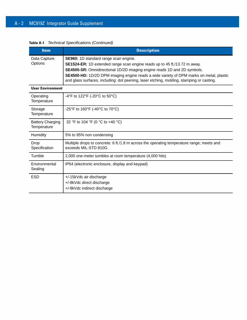
Data Capture Options
SE960: 1D standard range scan engine.SE1524-ER: 1D extended range scan engine reads up to 45 ft./13.72 m away.SE4500-SR: Omnidirectional 1D/2D imaging engine reads 1D and 2D symbols.SE4500-HD: 1D/2D DPM imaging engine reads a wide variety of DPM marks on metal, plastic and glass surfaces, including: dot peening, laser etching, molding, stamping or casting.
User Environment
Operating Temperature
-4°F to 122°F (-20°C to 50°C)
Storage Temperature
-25°F to 160°F (-40°C to 70°C)
Battery Charging Temperature
32 °F to 104 °F (0 °C to +40 °C)
Humidity 5% to 95% non condensing
Drop Specification
Multiple drops to concrete: 6 ft./1.8 m across the operating temperature range; meets and exceeds MIL-STD 810G
Tumble 2,000 one-meter tumbles at room temperature (4,000 hits)
Environmental Sealing
IP64 (electronic enclosure, display and keypad)
ESD +/-15kVdc air discharge+/-8kVdc direct discharge+/-8kVdc indirect discharge
Table A-1 Technical Specifications (Continued)
Item Description
Technical Specifications A - 3
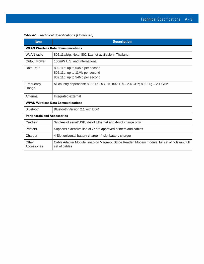
WLAN Wireless Data Communications
WLAN radio 802.11a/b/g. Note: 802.11a not available in Thailand.
Output Power 100mW U.S. and International
Data Rate 802.11a: up to 54Mb per second802.11b: up to 11Mb per second802.11g: up to 54Mb per second
Frequency Range
All country dependent: 802.11a - 5 GHz; 802.11b – 2.4 GHz; 802.11g – 2.4 GHz
Antenna Integrated external
WPAN Wireless Data Communications
Bluetooth Bluetooth Version 2.1 with EDR
Peripherals and Accessories
Cradles Single-slot serial/USB, 4-slot Ethernet and 4-slot charge only
Printers Supports extensive line of Zebra approved printers and cables
Charger 4-Slot universal battery charger, 4-slot battery charger
Other Accessories
Cable Adapter Module; snap-on Magnetic Stripe Reader; Modem module; full set of holsters; full set of cables
Table A-1 Technical Specifications (Continued)
Item Description
A - 4 MC919Z Integrator Guide Supplement
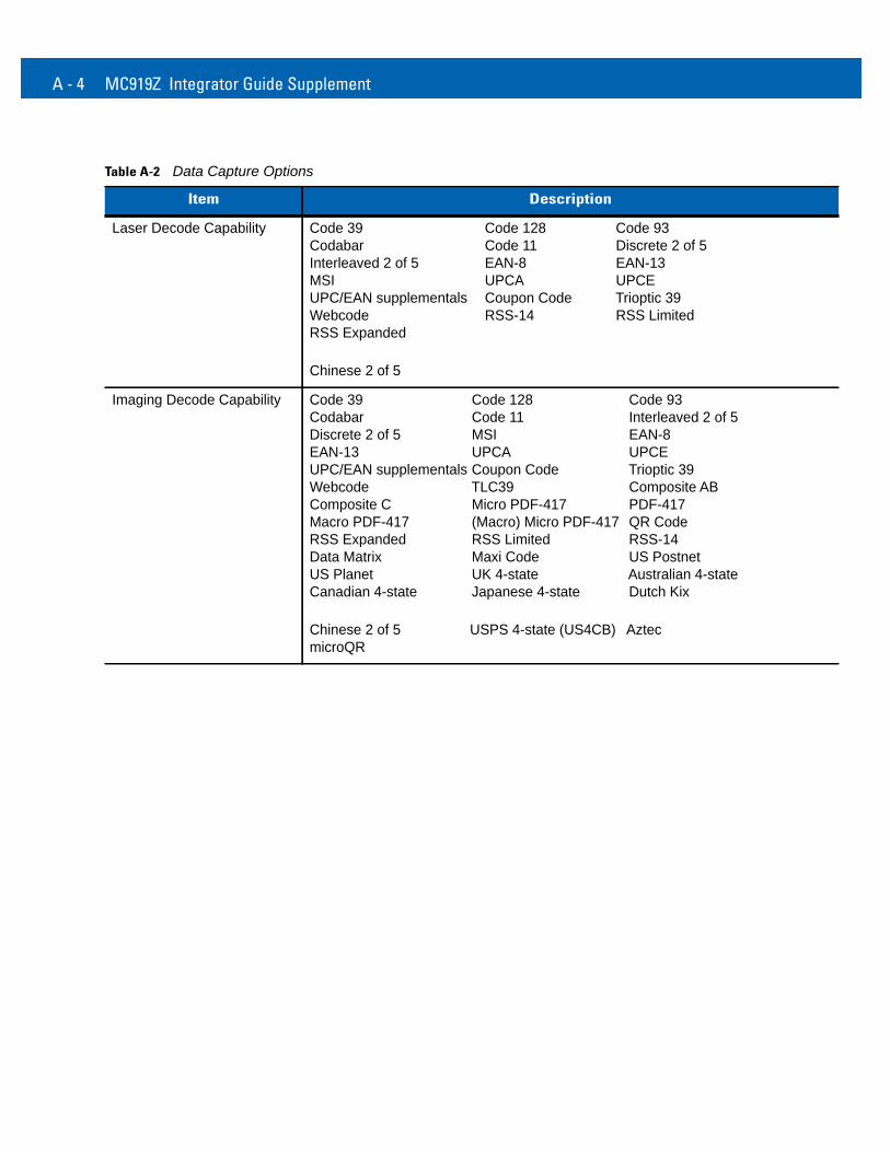
Table A-2 Data Capture Options
Item Description
Laser Decode Capability Code 39 Code 128 Code 93Codabar Code 11 Discrete 2 of 5Interleaved 2 of 5 EAN-8 EAN-13MSI UPCA UPCEUPC/EAN supplementals Coupon Code Trioptic 39Webcode RSS-14 RSS LimitedRSS Expanded
Chinese 2 of 5
Imaging Decode Capability Code 39 Code 128 Code 93Codabar Code 11 Interleaved 2 of 5Discrete 2 of 5 MSI EAN-8EAN-13 UPCA UPCEUPC/EAN supplementals Coupon Code Trioptic 39Webcode TLC39 Composite ABComposite C Micro PDF-417 PDF-417Macro PDF-417 (Macro) Micro PDF-417 QR CodeRSS Expanded RSS Limited RSS-14Data Matrix Maxi Code US PostnetUS Planet UK 4-state Australian 4-stateCanadian 4-state Japanese 4-state Dutch Kix
Chinese 2 of 5 USPS 4-state (US4CB) AztecmicroQR
Technical Specifications A - 5
Decode Zones
SE960 Standard Range Laser Decode Zones
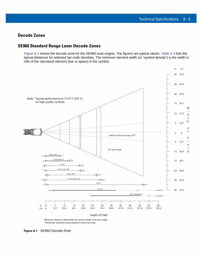
Figure A-1 shows the decode zone for the SE960 scan engine. The figures are typical values. Table A-3 lists the typical distances for selected bar code densities. The minimum element width (or “symbol density”) is the width in mils of the narrowest element (bar or space) in the symbol.
Figure A-1 SE960 Decode Zone
in.cm
00
5 mil Code 391.2 12.5
7.5 mil
100% UPC
1.1 18.5
27.0
52.0
100.0**
200.0**
5
5
in. cm
Widt
h
of
Field10
10
12.7
12.7
25.45 mil C128
1.2 7.7
10 mil Code 1281.2 19.0
1.6
15 mil Code 12829.51.0
1.4
3076.2
3588.9
40101.6
45114.3
15 38.1
20 50.8
15 38.1
20 50.8
20 mil
55 mil
100 mil Reflective
Note: Typical performance at 73.4o F (23o C) on high quality symbols.
*Minimum distance determined by symbol length and scan angle
Depth of Field
1025.4
1538.1
2050.8
2563.5
31.6
00
50127.0
60152.4
512.7
55127.0
25 63.5
30 76.2
25 63.5
30 76.2
3.4*
25
47o Scan Angle
Adaptive Scanning Angle (10o)
**Distances achieved using adaptive scanning mode.
A - 6 MC919Z Integrator Guide Supplement
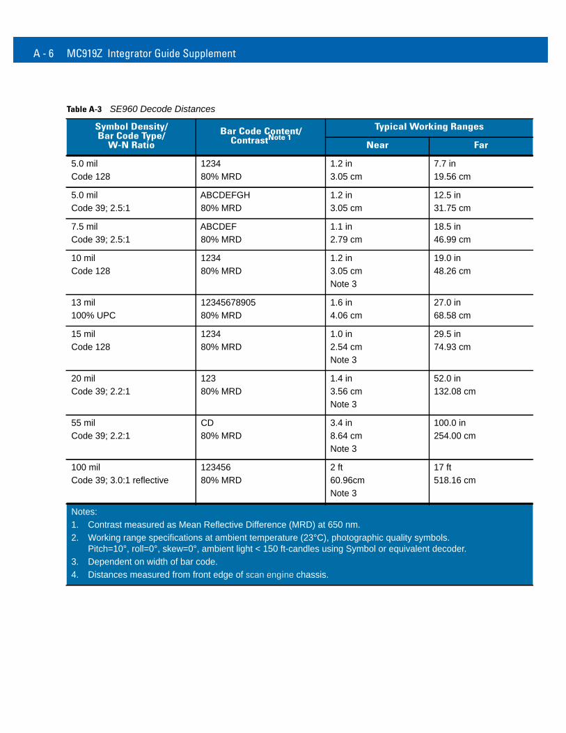
Table A-3 SE960 Decode Distances
Symbol Density/Bar Code Type/
W-N RatioBar Code Content/
ContrastNote 1Typical Working Ranges
Near Far
5.0 milCode 128
123480% MRD
1.2 in3.05 cm
7.7 in19.56 cm
5.0 milCode 39; 2.5:1
ABCDEFGH80% MRD
1.2 in3.05 cm
12.5 in31.75 cm
7.5 milCode 39; 2.5:1
ABCDEF80% MRD
1.1 in2.79 cm
18.5 in46.99 cm
10 milCode 128
123480% MRD
1.2 in3.05 cmNote 3
19.0 in48.26 cm
13 mil100% UPC
1234567890580% MRD
1.6 in4.06 cm
27.0 in68.58 cm
15 milCode 128
123480% MRD
1.0 in2.54 cmNote 3
29.5 in74.93 cm
20 milCode 39; 2.2:1
12380% MRD
1.4 in3.56 cmNote 3
52.0 in132.08 cm
55 milCode 39; 2.2:1
CD80% MRD
3.4 in8.64 cmNote 3
100.0 in254.00 cm
100 milCode 39; 3.0:1 reflective
12345680% MRD
2 ft60.96cmNote 3
17 ft518.16 cm
Notes:1. Contrast measured as Mean Reflective Difference (MRD) at 650 nm.2. Working range specifications at ambient temperature (23°C), photographic quality symbols.
Pitch=10°, roll=0°, skew=0°, ambient light < 150 ft-candles using Symbol or equivalent decoder.3. Dependent on width of bar code.4. Distances measured from front edge of scan engine chassis.
Technical Specifications A - 7
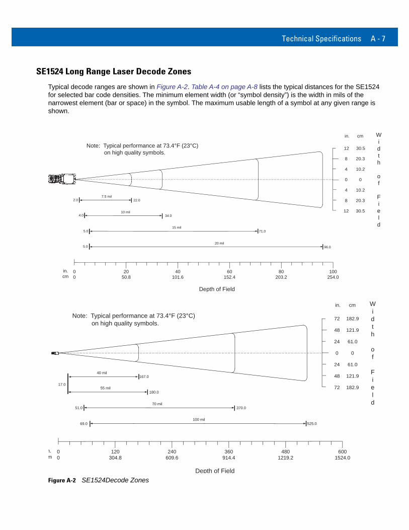
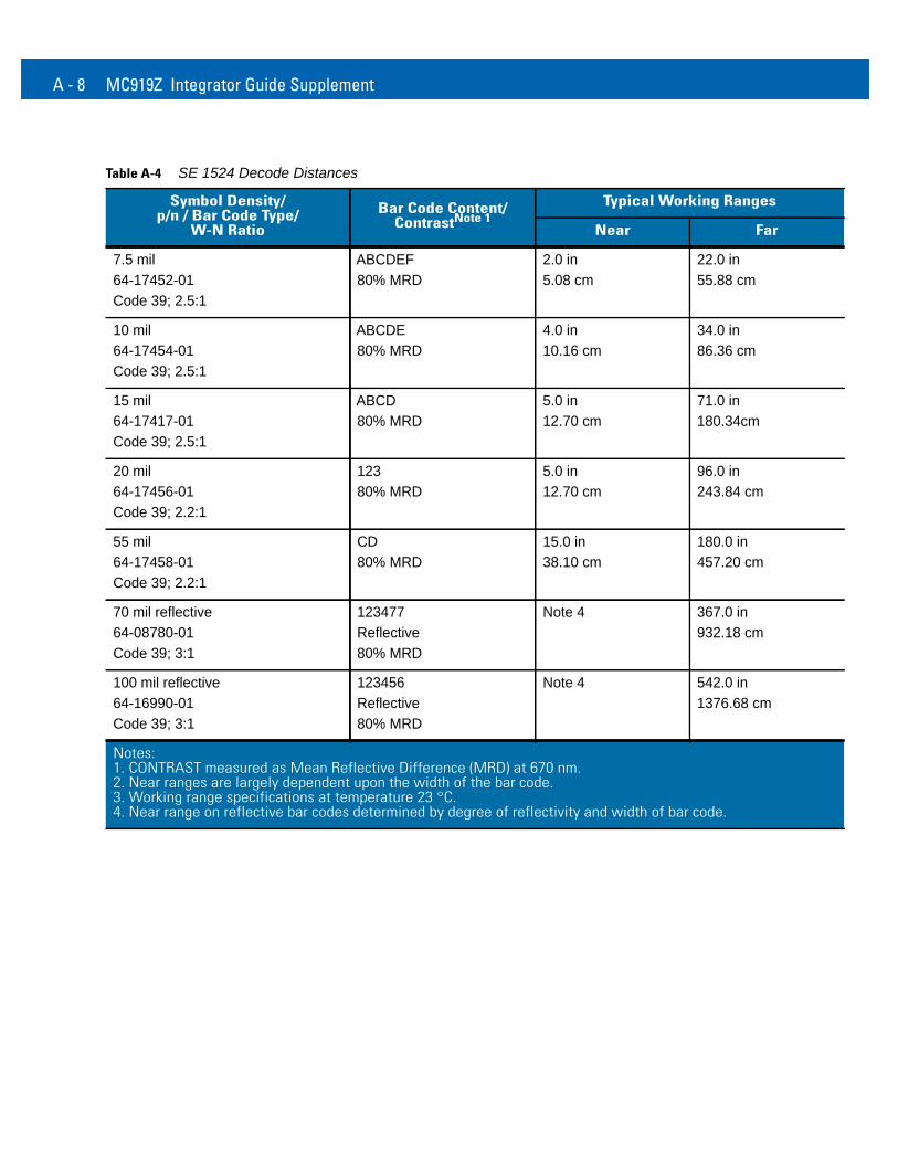
SE1524 Long Range Laser Decode Zones
Typical decode ranges are shown in Figure A-2. Table A-4 on page A-8 lists the typical distances for the SE1524 for selected bar code densities. The minimum element width (or “symbol density”) is the width in mils of the narrowest element (bar or space) in the symbol. The maximum usable length of a symbol at any given range is shown.
Figure A-2 SE1524Decode Zones
7.5 mil2.0 22.0
15 mil71.0
96.020 mil
in. cm Width
of
Field
Depth of Field
Note: Typical performance at 73.4°F (23°C) on high quality symbols.
5.0
0
4
8
12
8
12
5.0
10 mil34.04.0
in.cm
00
40101.6
2050.8
60152.4
80203.2
100254.0
4
0
10.2
20.3
30.5
20.3
30.5
10.2
55 mil17.0
180.0
100 mil525.0
in. cm Width
of
Field
Depth of Field
Note: Typical performance at 73.4°F (23°C) on high quality symbols.
0
24
48
72
48
72
69.0
70 mil370.051.0
n.m
00
240609.6
120304.8
360914.4
4801219.2
6001524.0
24
0
61.0
121.9
182.9
121.9
182.9
61.0
40 mil167.0
A - 8 MC919Z Integrator Guide Supplement
Table A-4 SE 1524 Decode Distances
Symbol Density/p/n / Bar Code Type/
W-N RatioBar Code Content/
ContrastNote 1Typical Working Ranges
Near Far
7.5 mil64-17452-01Code 39; 2.5:1
ABCDEF80% MRD
2.0 in5.08 cm
22.0 in55.88 cm
10 mil64-17454-01Code 39; 2.5:1
ABCDE80% MRD
4.0 in10.16 cm
34.0 in86.36 cm
15 mil64-17417-01Code 39; 2.5:1
ABCD80% MRD
5.0 in12.70 cm
71.0 in180.34cm
20 mil64-17456-01Code 39; 2.2:1
12380% MRD
5.0 in12.70 cm
96.0 in243.84 cm
55 mil64-17458-01Code 39; 2.2:1
CD80% MRD
15.0 in38.10 cm
180.0 in457.20 cm
70 mil reflective64-08780-01Code 39; 3:1
123477Reflective80% MRD
Note 4 367.0 in932.18 cm
100 mil reflective64-16990-01Code 39; 3:1
123456Reflective80% MRD
Note 4 542.0 in1376.68 cm
Notes:1. CONTRAST measured as Mean Reflective Difference (MRD) at 670 nm.2. Near ranges are largely dependent upon the width of the bar code.3. Working range specifications at temperature 23 °C.4. Near range on reflective bar codes determined by degree of reflectivity and width of bar code.
Technical Specifications A - 9
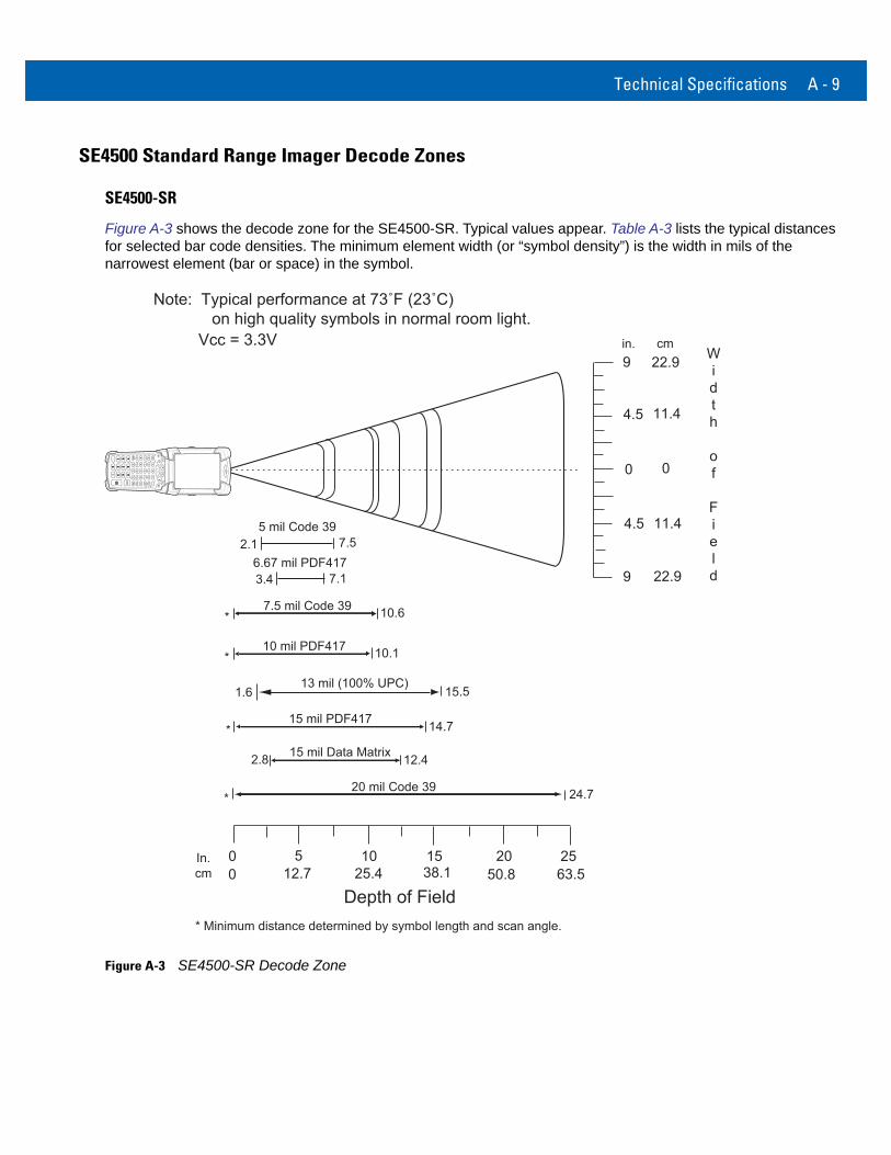
SE4500 Standard Range Imager Decode Zones
SE4500-SR
Figure A-3 shows the decode zone for the SE4500-SR. Typical values appear. Table A-3 lists the typical distances for selected bar code densities. The minimum element width (or “symbol density”) is the width in mils of the narrowest element (bar or space) in the symbol.
Figure A-3 SE4500-SR Decode Zone
In.cm
0
20 mil Code 39
Depth of Field
24.7
5 10 15 20 250 12.7 25.4 38.1 50.8 63.5
13 mil (100% UPC)
14.7
1.6 15.5
15 mil PDF417
0
cmWidth
of
Field
0
4.5 11.4
9 22.9
22.9
*
*
* Minimum distance determined by symbol length and scan angle.
9
11.4
in.
Note: Typical performance at 73˚F (23˚C) on high quality symbols in normal room light.
Vcc = 3.3V
4.5
12.415 mil Data Matrix2.8
10.110 mil PDF417*
10.67.5 mil Code 39*
6.67 mil PDF4173.4 7.1
5 mil Code 392.1 7.5
A - 10 MC919Z Integrator Guide Supplement
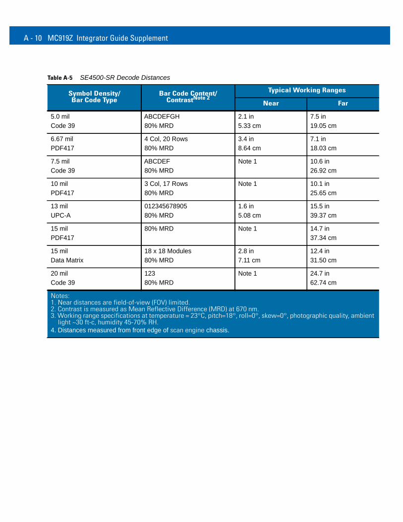
Table A-5 SE4500-SR Decode Distances
Symbol Density/Bar Code Type
Bar Code Content/ContrastNote 2
Typical Working Ranges
Near Far
5.0 milCode 39
ABCDEFGH80% MRD
2.1 in5.33 cm
7.5 in19.05 cm
6.67 mil PDF417
4 Col, 20 Rows80% MRD
3.4 in8.64 cm
7.1 in18.03 cm
7.5 milCode 39
ABCDEF80% MRD
Note 1 10.6 in26.92 cm
10 milPDF417
3 Col, 17 Rows80% MRD
Note 1 10.1 in25.65 cm
13 milUPC-A
01234567890580% MRD
1.6 in5.08 cm
15.5 in39.37 cm
15 milPDF417
80% MRD Note 1 14.7 in37.34 cm
15 milData Matrix
18 x 18 Modules80% MRD
2.8 in7.11 cm
12.4 in31.50 cm
20 milCode 39
12380% MRD
Note 1 24.7 in62.74 cm
Notes:1. Near distances are field-of-view (FOV) limited.2. Contrast is measured as Mean Reflective Difference (MRD) at 670 nm.3. Working range specifications at temperature = 23°C, pitch=18°, roll=0°, skew=0°, photographic quality, ambient
light ~30 ft-c, humidity 45-70% RH.4. Distances measured from front edge of scan engine chassis.
Technical Specifications A - 11
SE4500-HD
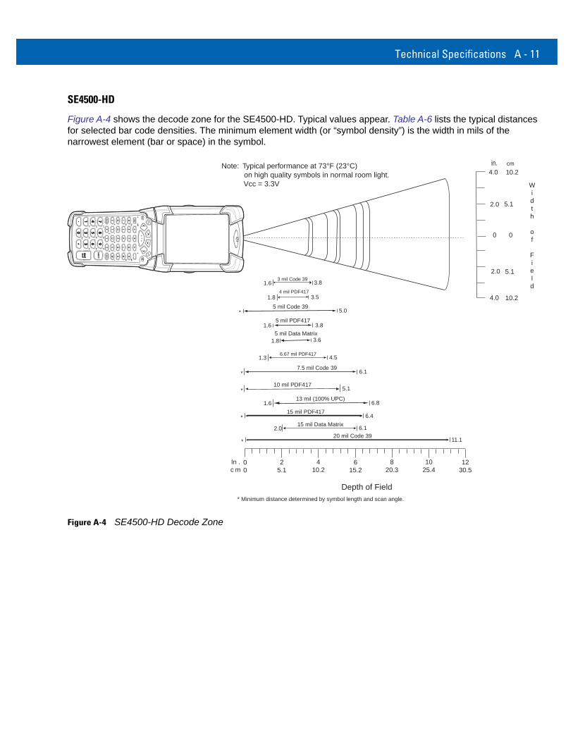
Figure A-4 shows the decode zone for the SE4500-HD. Typical values appear. Table A-6 lists the typical distances for selected bar code densities. The minimum element width (or “symbol density”) is the width in mils of the narrowest element (bar or space) in the symbol.
Figure A-4 SE4500-HD Decode Zone
Depth of Field
13 mil (100% UPC)
6.4
5 mil PDF417
1.6 6.8
1.6 3.8
15 mil PDF417
0
cm
Width
of
Field
0
5.1
4.0 10.2
10.2
*
* Minimum distance determined by symbol length and scan angle.
4.0 in.Note: Typical performance at 73°F (23°C)
on high quality symbols in normal room light. Vcc = 3.3V
7.5 mil Code 39* 6.1
6.67 mil PDF4171.3 4.5
10 mil PDF417* 5.1
4 mil PDF4171.8 3.5
2.0
5.12.0
3 mil Code 391.6 3.8
5 mil Code 39* 5.0
5 mil Data Matrix1.8 3.6
In .c m
00
1230.5
25.1
410.2
615.2
820.3
1025.4
11.120 mil Code 39
*
2.0 6.115 mil Data Matrix
A - 12 MC919Z Integrator Guide Supplement
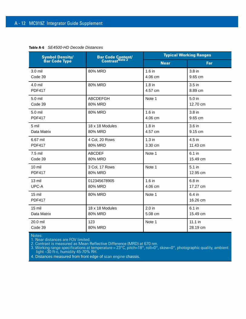
Table A-6 SE4500-HD Decode Distances
Symbol Density/Bar Code Type
Bar Code Content/ContrastNote 2
Typical Working Ranges
Near Far
3.0 milCode 39
80% MRD 1.6 in4.06 cm
3.8 in9.65 cm
4.0 mil PDF417
80% MRD 1.8 in4.57 cm
3.5 in8.89 cm
5.0 milCode 39
ABCDEFGH80% MRD
Note 1 5.0 in12.70 cm
5.0 milPDF417
80% MRD 1.6 in4.06 cm
3.8 in9.65 cm
5 milData Matrix
18 x 18 Modules80% MRD
1.8 in4.57 cm
3.6 in9.15 cm
6.67 mil PDF417
4 Col, 20 Rows80% MRD
1.3 in3.30 cm
4.5 in11.43 cm
7.5 milCode 39
ABCDEF80% MRD
Note 1 6.1 in15.49 cm
10 milPDF417
3 Col, 17 Rows80% MRD
Note 1 5.1 in12.95 cm
13 milUPC-A
01234567890580% MRD
1.6 in4.06 cm
6.8 in17.27 cm
15 milPDF417
80% MRD Note 1 6.4 in16.26 cm
15 milData Matrix
18 x 18 Modules80% MRD
2.0 in5.08 cm
6.1 in15.49 cm
20.0 milCode 39
12380% MRD
Note 1 11.1 in28.19 cm
Notes:1. Near distances are FOV limited.2. Contrast is measured as Mean Reflective Difference (MRD) at 670 nm.3. Working range specifications at temperature = 23°C, pitch=18°, roll=0°, skew=0°, photographic quality, ambient
light ~30 ft-c, humidity 45-70% RH.4. Distances measured from front edge of scan engine chassis.
Technical Specifications A - 13
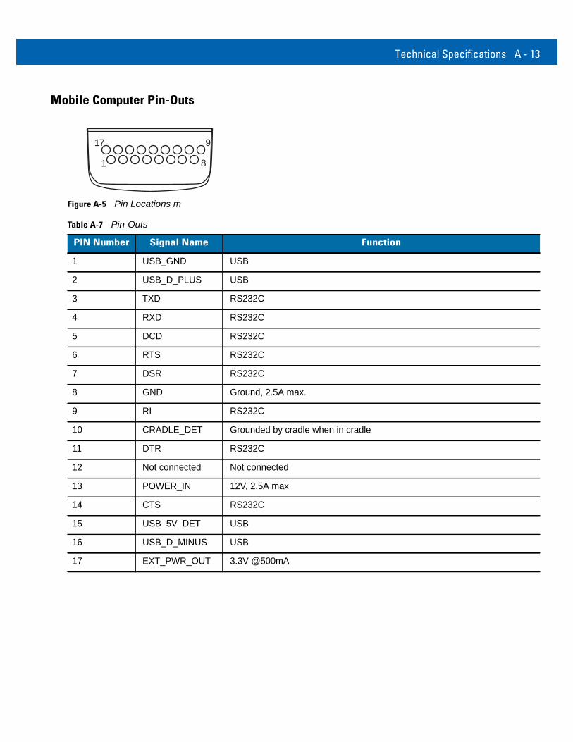
Mobile Computer Pin-Outs
Figure A-5 Pin Locations m
Table A-7 Pin-Outs
PIN Number Signal Name Function
1 USB_GND USB
2 USB_D_PLUS USB
3 TXD RS232C
4 RXD RS232C
5 DCD RS232C
6 RTS RS232C
7 DSR RS232C
8 GND Ground, 2.5A max.
9 RI RS232C
10 CRADLE_DET Grounded by cradle when in cradle
11 DTR RS232C
12 Not connected Not connected
13 POWER_IN 12V, 2.5A max
14 CTS RS232C
15 USB_5V_DET USB
16 USB_D_MINUS USB
17 EXT_PWR_OUT 3.3V @500mA
1 8
17 9
A - 14 MC919Z Integrator Guide Supplement
Accessory Specifications
Single Slot Serial/USB Cradle
Four Slot Ethernet Cradle
Table A-8 Single SLot Serial/USB Cradle Technical Specifications
Feature Description
Dimensions Height: 13.02 cm (5.13 in.)Width: 15.24 cm (6.0 in.)Depth: 15.24 cm (6.0 in.)
Input Power 12 VDC
Interface Serial and USB
Operating Temperature -25°C to 50°C (-13°F to 122°F)
Storage Temperature -40°C to 70°C (-40°F to 158°F)
Charging Temperature 0°C to 40°C (32°F to 104°F)
Humidity 5% to 95% non-condensing
Drop 76.2 cm (30.0 in.) drops to vinyl tiled concrete at room temperature
Electrostatic Discharge (ESD) +/- 15 kV air+/- 8 kV contact
Table A-9 Four Slot Ethernet Cradle Technical Specifications
Feature Description
Dimensions Height: 10.16 cm (4.0 in.)Width: 48.77 cm (19.00 in.)Depth:15.24 cm (6.0 in.)
Input Power 12 VDC
Interface Ethernet
Operating Temperature -25°C to 50°C (-13°F to 122°F)
Storage Temperature -40°C to 70°C (-40°F to 158°F)
Charging Temperature 0°C to 40°C (32°F to 104°F)
Technical Specifications A - 15
Four Slot Charge Only Cradle
Four Slot Battery Charger
Humidity 5% to 95% non-condensing
Drop 76.2 cm (30.0 in.) drops to vinyl tiled concrete at room temperature
Electrostatic Discharge (ESD) +/- 15 kV air+/- 8 kV contact
Table A-9 Four Slot Ethernet Cradle Technical Specifications (Continued)
Feature Description
Table A-10 Four Slot Charge Only Cradle Technical Specifications
Feature Description
Dimensions Height: 10.16 cm (4.0 in.)Width: 48.77 cm (19.00 in.)Depth:15.24 cm (6.0 in.)
Input Power 12 VDC
Operating Temperature -25°C to 50°C (-13°F to 122°F)
Storage Temperature -40°C to 70°C (-40°F to 158°F)
Charging Temperature 0°C to 40°C (32°F to 104°F)
Humidity 5% to 95% non-condensing
Drop 76.2 cm (30.0 in.) drops to vinyl tiled concrete at room temperature
Electrostatic Discharge (ESD) +/- 15 kV air+/- 8 kV contact
Table A-11 Four Slot Battery Charger Technical Specifications
Feature Description
Dimensions Height: 10.16 cm (4.0 in.)Width: 15.24 cm (6.0 in.)Depth: 15.24 cm (6.0 in.)
Input Power 12 VDC
Operating Temperature 0°C to 45°C (32°F to 113°F)
Storage Temperature -40°C to 70°C (-40°F to 158°F)
Charging Temperature 0°C to 40°C (32°F to 104°F)
A - 16 MC919Z Integrator Guide Supplement
Magnetic Stripe ReaderFigure A-6 Magnetic Stripe Reader (MSR) Technical Specifications (Continued)
Humidity 5% to 95% non-condensing
Drop 76.2 cm (30.0 in.) drops to vinyl tiled concrete at room temperature
Electrostatic Discharge (ESD) +/- 15 kV air+/- 8 kV contact
Table A-11 Four Slot Battery Charger Technical Specifications (Continued)
Feature Description
Feature Description
Interface Serial with baud rate up to 19,200
Format ANSI, ISO, AAMVA, CA DMV, user-configurable generic format
Swipe Speed 5 to 50 in. (127 to 1270 mm) /sec, bi-directional
Decoders Generic, Raw Data
Mode Buffered, unbuffered
Track Reading Capabilities Tracks 1 and 3: 210 bpiTrack 2: 75 and 210 bpi, autodetect
Operating Temperature -25°C to 50°C (-13°F to 122°F)
Storage Temperature -40°C to 70°C (-40°F to 158°F)
Humidity 5% to 95% non-condensing
Drop 1.22 m (4 ft.) drops to concrete
Electrostatic Discharge (ESD) +/- 15 kV air+/- 8 kV contact
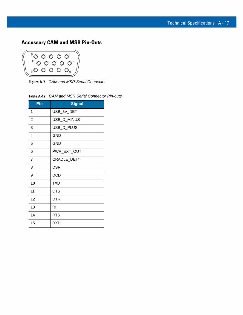
Technical Specifications A - 17
Accessory CAM and MSR Pin-Outs
Figure A-7 CAM and MSR Serial Connector
Table A-12 CAM and MSR Serial Connector Pin-outs
Pin Signal
1 USB_5V_DET
2 USB_D_MINUS
3 USB_D_PLUS
4 GND
5 GND
6 PWR_EXT_OUT
7 CRADLE_DET*
8 DSR
9 DCD
10 TXD
11 CTS
12 DTR
13 RI
14 RTS
15 RXD

A - 18 MC919Z Integrator Guide Supplement

Appendix B RFID APIs
RFID APIs are available in C, .NET, and Java. For information on supported RFID APIs, refer to the Enterprise Mobility Developer Kit (EMDK), available at http://www.zebra.com/support
For C, refer to the EMDK for C v2.1 or later. For .Net, refer to the EMDK for .NET v2.2 or later.

B - 2 MC919Z Integrator Guide Supplement
Index
Aactivesync . . . . . . . . . . . . . . . . . . . . . . . . . . . . . . . . . 2-1antenna . . . . . . . . . . . . . . . . . . . . . . . . . . . . . . . .1-2, 1-3APIs . . . . . . . . . . . . . . . . . . . . . . . . . . . . . . . . . . . . . . B-1
Bbattery charging temperature . . . . . . . . . . . . . . . . . . A-2bullets . . . . . . . . . . . . . . . . . . . . . . . . . . . . . . . . . . . . . . x
Cconfiguration . . . . . . . . . . . . . . . . . . . . . . . . . . . . . . . . .ixconfiguring MobileRFID . . . . . . . . . . . . . . . . . . . . . . . 3-7
region . . . . . . . . . . . . . . . . . . . . . . . . . . . . . . . . . 3-4connection
sample application . . . . . . . . . . . . . . . . . . . . . . . 4-3conventions
notational . . . . . . . . . . . . . . . . . . . . . . . . . . . . . . . . xCPU . . . . . . . . . . . . . . . . . . . . . . . . . . . . . . . . . . . . . . A-1
DDCP for MC9090w . . . . . . . . . . . . . . . . . . . . . . . . . . . . .xidecode distances . . . . . . . . . . . . . . . . . . . . . . . . A-6, A-8
HD focus . . . . . . . . . . . . . . . . . . . . . . . . . . . . . . A-12SR focus . . . . . . . . . . . . . . . . . . . . . . . . . . . . . . A-10
decode zone . . . . . . . . . . . . . . . . . . . . . . . . . . . . . . . A-5decode zones . . . . . . . . . . . . . . . . . . . . . . . . . . A-7, A-9
DL focus . . . . . . . . . . . . . . . . . . . . . . . . . . . . . . A-10HD focus . . . . . . . . . . . . . . . . . . . . . . . . . . . . . . A-11
demo . . . . . . . . . . . . . . . . . . . . . . . . . . . . . . . . . . . . . 4-1connection . . . . . . . . . . . . . . . . . . . . . . . . . . . . . . 4-3launching . . . . . . . . . . . . . . . . . . . . . . . . . . . . . . . 4-2
Device Configuration Package for MC9090w . . . . . . . .xidimensions . . . . . . . . . . . . . . . . . . . . . . . . . . . . . . . . A-1
display . . . . . . . . . . . . . . . . . . . . . . . . . . . . . . . . . . . . A-1drop specification . . . . . . . . . . . . . . . . . . . . . . . . . . . A-2
EEMDK for eVC4 . . . . . . . . . . . . . . . . . . . . . . . . . . . . . . .xiEnterprise Mobility Developer Kit for eVC4 . . . . . . . . . .xi
Ffirmware update . . . . . . . . . . . . . . . . . . . . . . . . . . . . 2-2
HHD focus decode distances . . . . . . . . . . . . . . . . . . A-12humidity . . . . . . . . . . . . . . . . . . . . . . . . . . . . . . . . . . . A-2
Iicons
MobileRFID . . . . . . . . . . . . . . . . . . . . . . . . . . . . . 3-2image update . . . . . . . . . . . . . . . . . . . . . . . . . . . . . . 2-1
activesync . . . . . . . . . . . . . . . . . . . . . . . . . . . . . . 2-1update loader . . . . . . . . . . . . . . . . . . . . . . . . . . . 2-1
information, service . . . . . . . . . . . . . . . . . . . . . . . . . . . .xi
Kkeyboard . . . . . . . . . . . . . . . . . . . . . . . . . . . . . . . . . . A-1
Llocating tags . . . . . . . . . . . . . . . . . . . . . . . . . . . . . . . 5-1
Mmemory . . . . . . . . . . . . . . . . . . . . . . . . . . . . . . . . . . . A-1
Index - 2 MC919Z Integrator Guide Supplement
MobileRFID . . . . . . . . . . . . . . . . . . . . . . . . . . . . . . . . 3-1client mode . . . . . . . . . . . . . . . . . . . . . . . . . . . . . 3-7configuring . . . . . . . . . . . . . . . . . . . . . . . . . . . . . 3-7configuring region . . . . . . . . . . . . . . . . . . . . . . . . 3-4icons . . . . . . . . . . . . . . . . . . . . . . . . . . . . . . . . . . 3-2menu . . . . . . . . . . . . . . . . . . . . . . . . . . . . . . . . . . 3-3server mode . . . . . . . . . . . . . . . . . . . . . . . . . . . . 3-7starting . . . . . . . . . . . . . . . . . . . . . . . . . . . . . . . . 3-9stopping . . . . . . . . . . . . . . . . . . . . . . . . . . . . . . . 3-9version information . . . . . . . . . . . . . . . . . . . . . . . 3-8
Ooperating system . . . . . . . . . . . . . . . . . . . . . . . . . . . . A-1operating temperature . . . . . . . . . . . . . . . . . . . . . . . . A-2
Ppin-outs
accessory . . . . . . . . . . . . . . . . . . . . . . . . . . . . . A-17mobile computer . . . . . . . . . . . . . . . . . . . . . . . . A-13
Rradio . . . . . . . . . . . . . . . . . . . . . . . . . . . . . . . . . . . . . . 1-2region
configuring . . . . . . . . . . . . . . . . . . . . . . . . . . . . . 3-4RFID APIs . . . . . . . . . . . . . . . . . . . . . . . . . . . . . . . . . B-1RFID components . . . . . . . . . . . . . . . . . . . . . . . . . . . 1-2
antennas . . . . . . . . . . . . . . . . . . . . . . . . . . . . . . . 1-2radio . . . . . . . . . . . . . . . . . . . . . . . . . . . . . . . . . . 1-2tags . . . . . . . . . . . . . . . . . . . . . . . . . . . . . . . . . . . 1-2
RFID firmware update . . . . . . . . . . . . . . . . . . . . . . . . 2-2RFID overview . . . . . . . . . . . . . . . . . . . . . . . . . . . . . . 1-1
Ssample application . . . . . . . . . . . . . . . . . . . . . . . . . . . 4-1
connection . . . . . . . . . . . . . . . . . . . . . . . . . . . . . . 4-3launching . . . . . . . . . . . . . . . . . . . . . . . . . . . . . . . 4-2
SR focus decode distances . . . . . . . . . . . . . . . . . . . A-10starting RFID . . . . . . . . . . . . . . . . . . . . . . . . . . . . . . . 3-9stopping RFID . . . . . . . . . . . . . . . . . . . . . . . . . . . . . . 3-9storage temperature . . . . . . . . . . . . . . . . . . . . . . . . . A-2
Ttags . . . . . . . . . . . . . . . . . . . . . . . . . . . . . . . . . . . . . . 1-2
locating . . . . . . . . . . . . . . . . . . . . . . . . . . . . . . . . 5-1troubleshooting . . . . . . . . . . . . . . . . . . . . . . . . . . . . . 6-1
Uupdating device . . . . . . . . . . . . . . . . . . . . . . . . . . . . . 2-1
activesync . . . . . . . . . . . . . . . . . . . . . . . . . . . . . . 2-1firmware . . . . . . . . . . . . . . . . . . . . . . . . . . . . . . . . 2-2RFID firmware . . . . . . . . . . . . . . . . . . . . . . . . . . . 2-2update loader . . . . . . . . . . . . . . . . . . . . . . . . . . . 2-1
Wweight . . . . . . . . . . . . . . . . . . . . . . . . . . . . . . . . . . . . . A-1


72E-157455-02 Revision A - March 2015
Zebra Technologies CorporationLincolnshire, IL U.S.A.http://www.zebra.com
Zebra and the Zebra head graphic are registered trademarks of ZIH Corp. The Symbol logo is a registered trademark of Symbol Technologies, Inc., a ZebraTechnologies company.
© 2015 Symbol Technologies, Inc.