mcac-2008-11 air-cooled modular chiller contents · mcac-2008-11 air-cooled modular chiller 1...
TRANSCRIPT
MCAC-2008-11 Air-cooled Modular Chiller
1
Contents
1. Nomenclature…………..………………………………………………...
2. Product Schedule………………………………………………………..
3. Features…………………………………………………………………...
4. Specification……………………………………………………………...
5. Dimension…………………………………………………………………
6. Piping Diagrams & Pipe Connection Drawing……………………...
7. Wiring Diagrams……………………….………………………………..
8. Electric Characteristics…………………………………………….......
9. Capacity Tables…………………………………………………………
10. Exploded View………………………………………………………….
11. Troubleshooting……………..…………………………………………
12. Installation……………………………..………………………………..
13. Debugging...…………………………..………………………………
14. Maintenance…..…………………………..……………………………
15. Control……………………………..……………………………………. ※ Manufacture reserves the right to discontinue, or change at any time, specifications or designs without notices and without incurring obligations.

MCAC-2008-11 Air-cooled Modular Chiller
2
1. Nomenclature
RefrigerantN1 R410A -- R22
Power SupplyS 380V~,50Hz,3Ph
Outdoor Unit
Cooling Capacity(kW)
Compressor TypeD Digital Scroll CompressorF Fixed speed Scroll Compressor
Modular Air-Cooled Chiller SystemA Time A Design
Light Commercial Chiller System
Midea
M G A - D 65 W/S N1

MCAC-2008-11 Air-cooled Modular Chiller
3
2. Product Schedule Net dimension Net weight
No Model Refrigerant (L×W×H) (unit: mm) (kg)
Power supply
1 MGA-F30W/SN1 R410A 1514×850×1820 440 380-415V/3ph/50Hz
2 MGA-F65W/SN1 R410A 2492×850×1820 700 380-415V/3ph/50Hz
3 MGA-D30W/SN1 R410A 1514×850×1820 440 380-415V/3ph/50Hz
4 MGA-D65W/SN1 R410A 2492×850×1820 700 380-415V/3ph/50Hz
External appearance:
30 kW module 65kW module

MCAC-2008-11 Air-cooled Modular Chiller
4
3. Features Environmental-friendly refrigerant R410A will not destroy the ozonosphere. Modular design, flexible combination, more convenient for design and installation. The maximum combination of the system consists of 1 main unit and 7 slave units (for 30kW
unit, 15 slave units, so maximum capacity can reach 520kW).
Adopts digital scroll compressor, the capacity can be realized stepless adjustment.
Chilled water outlet temperature adjustable.
Chilled water outlet temperature can be adjusted by wire controller according to customer’s demand. In cooling mode, the adjustable range from 5-17, and in heating mode, it ranges from 45-50.
High reliability and efficiency. Digital and constant module unit can be combined into one group water pipe system and control system. The capacity output can be adjusted and the load of different module unit can be distributed uniformly by control system. The unit system can adjust output according to requirement without energy waste.

MCAC-2008-11 Air-cooled Modular Chiller
5
Easy connection between main unit and slave units.
Connecting all the units together with a wired controller in series type. Using two-core shielded twisted wire as communication signal wire. Any of unit can be set as main unit by setting its address No.0, the other as slave units.
Strong micro-computer intelligent control and monitor function. Stepless capacity modulation, more efficiency. Operation mode control. Automatic and uniform adjusting function among multi compressors. Anti-frost and anti-cold air functions in heating mode. Anti-freezing function of water system in winter. Self-protection and Self-diagnosis function. Realize auto-restart function with wired controller. Built-in remote ON-OFF switch.

MCAC-2008-11 Air-cooled Modular Chiller
6
4. Specification For fix speed heat pump 30kW module:
MGA-F( )W/SN1 Model
30 60 90 120 150 180 210 240
Combination (Main module + auxiliary module) Pieces 1+0 1+1 1+2 1+3 1+4 1+5 1+6 1+7
Cooling Capacity kW 30 60 90 120 150 180 210 240
Heating Capacity kW 32 64 96 128 160 192 224 256
Power supply V/Ph/Hz 380-415/3/50
Type Scroll (fixed speed) Compressor
Quantities Pieces 2 4 6 8 10 12 14 16
Cooling kW 10 20 30 40 50 60 70 80 Power input
Heating kW 9.8 19.5 29.3 39 48.8 58.5 68.3 78
Type R410A Refrigerant
Weight kg 7 7×2 7×3 7×4 7×5 7×6 7×7 7×8
Air side heat-exchanger type Copper-fin-coil
Quantities of fan motor Pieces 1 2 3 4 5 6 7 8
Air flow volume ×103m3/h 12 24 36 48 60 72 84 96
Condenser
(Air side)
Fan motor input kW 0.7 0.7×2 0.7×3 0.7×4 0.7×5 0.7×6 0.7×7 0.7×8
Water side heat-exchanger type Plate type
Water resistance loss kPa 18 18 18 18 18 18 18 18
Water inlet/outlet pipeline diameter mm 133 133 133 133 133 133 133 133
Water flow volume m3/h 5.2 10.3 15.5 20.6 25.8 30.9 36 41.2
Max. Pressure MPa 1 1 1 1 1 1 1 1
Evaporator
(Water side)
Water pipe connection type Soft connection
L mm 1514 1514 1514 1514 1514 1514 1514 1514
W mm 850 2300 3750 5200 6650 8100 9550 11000Dimension
H mm 1820 1820 1820 1820 1820 1820 1820 1820
Packing size L×W×H mm 1620×1034×2041
Net weight kg 440 880 1320 1760 2200 2640 3080 3520 Weight
Operating weight kg 470 940 1410 1880 2350 2820 3290 3760
Power wiring mm2×No. 10×5-core Connection
wiring Signal wiring mm2×No. 0.75×3-core
Control type Wired controller
Safety protection device High/low-pressure switch, anti-frost protection, water-flow switch, over-load
protection, and power phases sequence protection.
Power supply V/Ph/Hz 380/3/50 Electric
heater
(optional) Power input W 7.5 15 22.5 30 37.5 45 52.5 60
Noise level dB(A) 58
Operation water temp Cooling:5~17 Heating:45~50
Ambient temp Cooling:17~48 Heating:-10~21
Note: Please refer to the water flow volume in the above table strictly to design and install.

MCAC-2008-11 Air-cooled Modular Chiller
7
For fix speed heat pump 30kW module: MGA-F( )W/SN1
Model 270 300 330 360 390 420 450 480
Combination (Main module + auxiliary
module) Pieces 1+8 1+9 1+10 1+11 1+12 1+13 1+14 1+15
Cooling Capacity kW 270 300 330 360 390 420 450 480
Heating Capacity kW 288 320 352 384 416 448 480 512
Power supply V/Ph/Hz 380-415/3/50
Type Scroll (fixed speed) Compressor
Quantities Pieces 18 20 22 24 26 28 30 32
Cooling kW 90 100 110 120 130 140 150 160 Power input
Heating kW 87.8 97.5 107.3 117 126.8 136.5 146.3 156
Type R410A Refrigerant
Weight kg 7×9 7×10 7×11 7×12 7×13 7×14 7×15 7×16
Air side
heat-exchanger type Copper-fin-coil
Quantities of fan
motor Pieces 9 10 11 12 13 14 15 16
Air flow volume ×103m3/h 108 120 132 144 156 168 180 192
Condenser (Air
side)
Fan motor input kW 0.7×9 0.7×10 0.7×11 0.7×12 0.7×13 0.7×14 0.7×15 0.7×16
Water side
heat-exchanger type Plate type
Water resistance loss kPa 18 18 18 18 18 18 18 18
Water inlet/outlet
pipeline diameter mm 133 133 133 133 133 133 133 133
Water flow volume m3/h 46.4 51.5 56.7 61.8 67 72.1 77.3 82.4
Max. Pressure MPa 1 1 1 1 1 1 1 1
Evaporator
(Water side)
Water pipe
connection type Soft connection
L mm 1514 1514 1514 1514 1514 1514 1514 1514
W mm 12450 13900 15350 16800 18250 19700 21150 22600 Dimension
H mm 1820 1820 1820 1820 1820 1820 1820 1820
Packing size L×W×H mm 1620×1034×2041
Net weight kg 3960 4400 4840 5280 5720 6160 6600 7040 Weight
Operating weight kg 4230 4700 5170 5640 6110 6580 7050 7520
Power wiring mm2×No. 10×5-core Connection
wiring Signal wiring mm2×No. 0.75×3-core
Control type Wired controller
Safety protection device High/low-pressure switch, anti-frost protection, water-flow switch, over-load protection, and
power phases sequence protection.
Power supply V/Ph/Hz 380/3/50 Electric heater
(optional) Power input W 67.5 75 82.5 90 97.5 105 112.5 120
Noise level dB(A) 58
Operation water temp Cooling:5~17 Heating:45~50
Ambient temp Cooling:17~48 Heating:-10~21
Note: Please refer to the water flow volume in the above table strictly to design and install.

MCAC-2008-11 Air-cooled Modular Chiller
8
For fix speed heat pump 65kW module: MGA-F( )W/SN1
Model 65 130 195 260 325 390 455 520
Combination (Main module + auxiliary
module) Pieces 1+0 1+1 1+2 1+3 1+4 1+5 1+6 1+7
Cooling Capacity kW 65 130 195 260 325 390 455 520
Heating Capacity kW 69 139 207 276 345 414 483 552
Power supply V/Ph/Hz 380/3/50
Type Scroll (fixed speed) Compressor
Quantities Pieces 4 8 12 16 20 24 28 32
Cooling kW 21.5 43 64.5 86 107.5 129 150.5 172 Power input
Heating kW 21 42 63 84 105 126 147 168
Type R410A R410A R410A R410A R410A R410A R410A R410ARefrigerant
Weight kg 14 14×2 14×3 14×4 14×5 14×6 14×7 14×8
Air side heat-exchanger type Copper-fin-coil
Quantities of fan motor Pieces 2 4 6 8 10 12 14 16
Air flow volume ×103m3/h 24 24×2 24×3 24×4 24×5 24×6 24×7 24×8
Condenser
(Air side)
Fan motor input kW 0.7×2 0.7×4 0.7×6 0.7×8 0.7×10 0.7×12 0.7×14 0.7×16
Water side heat-exchanger
type Plate type
Water resistance loss kPa 29.4 29.4 29.4 29.4 29.4 29.4 29.4 29.4
Water inlet/outlet pipeline
diameter mm 133 133 133 133 133 133 133 133
Water flow volume m3/h 11.2 22.4 33.6 44.8 56 67.2 78.4 89.6
Max. Pressure MPa 1 1 1 1 1 1 1 1
Evaporator
(Water side)
Water pipe connection type Soft connection
L mm 2492 2492 2492 2492 2492 2492 2492 2492
W mm 850 2300 3750 5200 6650 8100 9550 11000 Dimension
H mm 1820 1820 1820 1820 1820 1820 1820 1820
Packing
size L×W×H mm 2612×1034×2041
Net weight kg 700 1400 2100 2800 3500 4200 4900 5600 Weight
Operating weight kg 765 1530 2295 3060 3825 4590 5355 6120
Power wiring mm2×No. 10×5-core Connection
wiring Signal wiring mm2×No. 0.75×3-core
Control type Wired controller
Safety protection device High/low-pressure switch, anti-frost protection, water-flow switch, over-load protection,
and power phases sequence protection.
Power supply V/Ph/Hz 380/3/50 Electric
heater
(optional) Power input W 15 30 45 60 75 90 105 120
Noise level dB(A) 60
Operation water temp Cooling:5~17 Heating:45~50
Ambient temp Cooling:17~48 Heating:-10~21
Note: Please refer to the water flow volume in the above table strictly to design and install.

MCAC-2008-11 Air-cooled Modular Chiller
9
For digital scroll heat pump 30kW module: MGA-D( )W/SN1
Model 30 60 90 120 150 180 210 240
Combination (Main module + auxiliary module) Pieces 1+0 1+1 1+2 1+3 1+4 1+5 1+6 1+7
Cooling Capacity kW 30 60 90 120 150 180 210 240
Heating Capacity kW 32 64 96 128 160 192 224 256
Power supply V/Ph/Hz 380-415/3/50
Type Scroll (1 digital scroll plus 1 fixed speed) Compressor
Quantities Pieces 2 4 6 8 10 12 14 16
Cooling kW 10 20 30 40 50 60 70 80 Power input
Heating kW 9.8 19.5 29.3 39 48.8 58.5 68.3 78
Type R410A R410A R410A R410A R410A R410A R410A R410ARefrigerant
Weight kg 7 7×2 7×3 7×4 7×5 7×6 7×7 7×8
Air side heat-exchanger type Copper-fin-coil
Quantities of fan motor Pieces 1 2 3 4 5 6 7 8
Air flow volume ×103m3/h 12 24 36 48 60 72 84 96
Condenser
(Air side)
Fan motor input kW 0.7 0.7×2 0.7×3 0.7×4 0.7×5 0.7×6 0.7×7 0.7×8
Water side heat-exchanger type Plate type
Water resistance loss kPa 18 18 18 18 18 18 18 18
Water inlet/outlet pipeline diameter mm 133 133 133 133 133 133 133 133
Water flow volume m3/h 5.2 10.3 15.5 20.6 25.8 30.9 36 41.2
Max. Pressure MPa 1 1 1 1 1 1 1 1
Evaporator
(Water side)
Water pipe connection type Soft connection
L mm 1514 1514 1514 1514 1514 1514 1514 1514
W mm 850 2300 3750 5200 6650 8100 9550 11000Dimension
H mm 1820 1820 1820 1820 1820 1820 1820 1820
Packing
size L×W×H mm 1620×1034×2041
Net weight kg 440 880 1320 1760 2200 2640 3080 3520 Weight
Operating weight kg 470 940 1410 1880 2350 2820 3290 3760
Power wiring mm2×No. 10×5-core Connection
wiring Signal wiring mm2×No. 0.75×3-core
Control type Wired controller
Safety protection device High/low-pressure switch, anti-frost protection, water-flow switch, over-load
protection, and power phases sequence protection.
Power supply V/Ph/Hz 380/3/50 Electric
heater
(optional) Power input W 7.5 15 22.5 30 37.5 45 52.5 60
Noise level dB(A) 58
Operation water temp Cooling:5~17 Heating:45~50
Ambient temp Cooling:17~48 Heating:-10~21
Note: Please refer to the water flow volume in the above table strictly to design and install.
MCAC-2008-11 Air-cooled Modular Chiller
10
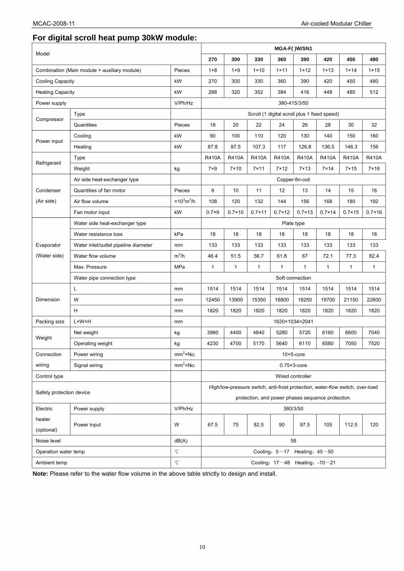
For digital scroll heat pump 30kW module: MGA-F( )W/SN1
Model 270 300 330 360 390 420 450 480
Combination (Main module + auxiliary module) Pieces 1+8 1+9 1+10 1+11 1+12 1+13 1+14 1+15
Cooling Capacity kW 270 300 330 360 390 420 450 480
Heating Capacity kW 288 320 352 384 416 448 480 512
Power supply V/Ph/Hz 380-415/3/50
Type Scroll (1 digital scroll plus 1 fixed speed) Compressor
Quantities Pieces 18 20 22 24 26 28 30 32
Cooling kW 90 100 110 120 130 140 150 160 Power input
Heating kW 87.8 97.5 107.3 117 126.8 136.5 146.3 156
Type R410A R410A R410A R410A R410A R410A R410A R410ARefrigerant
Weight kg 7×9 7×10 7×11 7×12 7×13 7×14 7×15 7×16
Air side heat-exchanger type Copper-fin-coil
Quantities of fan motor Pieces 9 10 11 12 13 14 15 16
Air flow volume ×103m3/h 108 120 132 144 156 168 180 192
Condenser
(Air side)
Fan motor input kW 0.7×9 0.7×10 0.7×11 0.7×12 0.7×13 0.7×14 0.7×15 0.7×16
Water side heat-exchanger type Plate type
Water resistance loss kPa 18 18 18 18 18 18 18 18
Water inlet/outlet pipeline diameter mm 133 133 133 133 133 133 133 133
Water flow volume m3/h 46.4 51.5 56.7 61.8 67 72.1 77.3 82.4
Max. Pressure MPa 1 1 1 1 1 1 1 1
Evaporator
(Water side)
Water pipe connection type Soft connection
L mm 1514 1514 1514 1514 1514 1514 1514 1514
W mm 12450 13900 15350 16800 18250 19700 21150 22600Dimension
H mm 1820 1820 1820 1820 1820 1820 1820 1820
Packing size L×W×H mm 1620×1034×2041
Net weight kg 3960 4400 4840 5280 5720 6160 6600 7040 Weight
Operating weight kg 4230 4700 5170 5640 6110 6580 7050 7520
Power wiring mm2×No. 10×5-core Connection
wiring Signal wiring mm2×No. 0.75×3-core
Control type Wired controller
Safety protection device High/low-pressure switch, anti-frost protection, water-flow switch, over-load
protection, and power phases sequence protection.
Power supply V/Ph/Hz 380/3/50 Electric
heater
(optional) Power input W 67.5 75 82.5 90 97.5 105 112.5 120
Noise level dB(A) 58
Operation water temp Cooling:5~17 Heating:45~50
Ambient temp Cooling:17~48 Heating:-10~21
Note: Please refer to the water flow volume in the above table strictly to design and install.
MCAC-2008-11 Air-cooled Modular Chiller
11
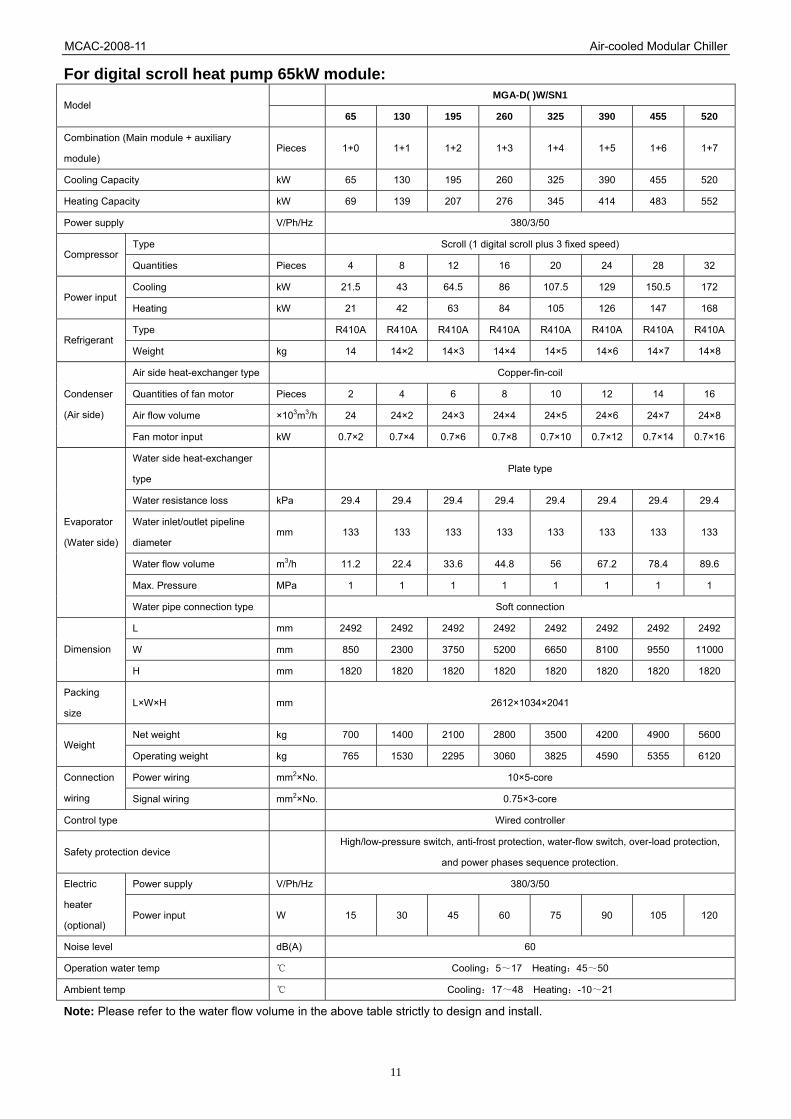
For digital scroll heat pump 65kW module: MGA-D( )W/SN1
Model 65 130 195 260 325 390 455 520
Combination (Main module + auxiliary
module) Pieces 1+0 1+1 1+2 1+3 1+4 1+5 1+6 1+7
Cooling Capacity kW 65 130 195 260 325 390 455 520
Heating Capacity kW 69 139 207 276 345 414 483 552
Power supply V/Ph/Hz 380/3/50
Type Scroll (1 digital scroll plus 3 fixed speed) Compressor
Quantities Pieces 4 8 12 16 20 24 28 32
Cooling kW 21.5 43 64.5 86 107.5 129 150.5 172 Power input
Heating kW 21 42 63 84 105 126 147 168
Type R410A R410A R410A R410A R410A R410A R410A R410ARefrigerant
Weight kg 14 14×2 14×3 14×4 14×5 14×6 14×7 14×8
Air side heat-exchanger type Copper-fin-coil
Quantities of fan motor Pieces 2 4 6 8 10 12 14 16
Air flow volume ×103m3/h 24 24×2 24×3 24×4 24×5 24×6 24×7 24×8
Condenser
(Air side)
Fan motor input kW 0.7×2 0.7×4 0.7×6 0.7×8 0.7×10 0.7×12 0.7×14 0.7×16
Water side heat-exchanger
type Plate type
Water resistance loss kPa 29.4 29.4 29.4 29.4 29.4 29.4 29.4 29.4
Water inlet/outlet pipeline
diameter mm 133 133 133 133 133 133 133 133
Water flow volume m3/h 11.2 22.4 33.6 44.8 56 67.2 78.4 89.6
Max. Pressure MPa 1 1 1 1 1 1 1 1
Evaporator
(Water side)
Water pipe connection type Soft connection
L mm 2492 2492 2492 2492 2492 2492 2492 2492
W mm 850 2300 3750 5200 6650 8100 9550 11000 Dimension
H mm 1820 1820 1820 1820 1820 1820 1820 1820
Packing
size L×W×H mm 2612×1034×2041
Net weight kg 700 1400 2100 2800 3500 4200 4900 5600 Weight
Operating weight kg 765 1530 2295 3060 3825 4590 5355 6120
Power wiring mm2×No. 10×5-core Connection
wiring Signal wiring mm2×No. 0.75×3-core
Control type Wired controller
Safety protection device High/low-pressure switch, anti-frost protection, water-flow switch, over-load protection,
and power phases sequence protection.
Power supply V/Ph/Hz 380/3/50 Electric
heater
(optional) Power input W 15 30 45 60 75 90 105 120
Noise level dB(A) 60
Operation water temp Cooling:5~17 Heating:45~50
Ambient temp Cooling:17~48 Heating:-10~21
Note: Please refer to the water flow volume in the above table strictly to design and install.

MCAC-2008-11 Air-cooled Modular Chiller
12
5. Dimension 5.1 30kW modular outline:
5.2 65kW modular outline:

MCAC-2008-11 Air-cooled Modular Chiller
13
6. Piping Diagrams & Pipe Connection Drawing 6.1 Refrigeration system sketch drawing for 30kW module unit 30kW module has two separate refrigeration systems (system A and system B), each system consists of one compressor and the two systems share one double-system plate exchanger.
Condenser
Throttle
Plate of exchanger
Water inlet
Water outlet
FilterFilter
Com
p 2
Gas-liquid separator
Com
p 1
Hig
h pr
essu
re s
witc
h
Low pressure switch
Four-way valve
6.2 Refrigeration system sketch drawing for 65kW: 65kW module has two unit modules; the refrigeration system sketch drawing of unit modules is above refrigeration system sketch drawing of 30kW. 6.3 Water pipe sketch drawing for 30kW module unit system:
Compressor Plate heat-exchanger Water input
Water output
Water output Water input

MCAC-2008-11 Air-cooled Modular Chiller
14
6.4 Water pipe sketch drawing for 65kW module unit system:
6.5 Sketch drawing of units combination system(30kW、65kW) Module unit can be combined by single unit, double units or both. By connecting each own inlet & outlet pipeline in series, 1-8 modules (2-16 units) can be combined and the max. cooling capacity is 520kW, unit system of principle is shown as follows:
65kw module 65kw module
Total water input pipe
30kw module
water pump
Total water output pipe water outlet temp. sensor plugging up flange

MCAC-2008-11 Air-cooled Modular Chiller
15
6.6 Sketch drawing of auxiliary electric heater installation
A Water heater/chiller unit I Gate valve 2
B Back flush valve J Gate valve 3
C Temperature-testing tube K Filter
D Pressure gauge L Flow switch
E Drain valve M Exhaust valve
F Absorbing pipe fittings N Safety valve
G Gate valve P Foundation
H Gate valve 1
MCAC-2008-11 Air-cooled Modular Chiller
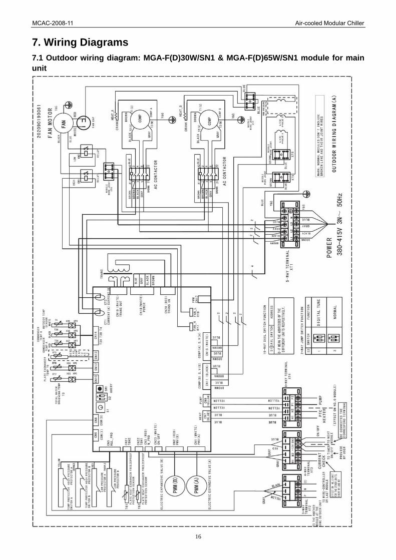
16
7. Wiring Diagrams 7.1 Outdoor wiring diagram: MGA-F(D)30W/SN1 & MGA-F(D)65W/SN1 module for main unit

MCAC-2008-11 Air-cooled Modular Chiller
17
7.2 Outdoor wiring diagram: MGA-F(D)30W/SN1 & MGA-F(D)65W/SN1 module for auxiliary unit
MCAC-2008-11 Air-cooled Modular Chiller
18
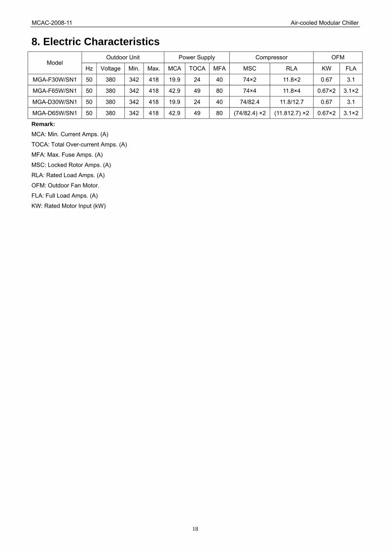
8. Electric Characteristics Outdoor Unit Power Supply Compressor OFM
Model Hz Voltage Min. Max. MCA TOCA MFA MSC RLA KW FLA
MGA-F30W/SN1 50 380 342 418 19.9 24 40 74×2 11.8×2 0.67 3.1
MGA-F65W/SN1 50 380 342 418 42.9 49 80 74×4 11.8×4 0.67×2 3.1×2
MGA-D30W/SN1 50 380 342 418 19.9 24 40 74/82.4 11.8/12.7 0.67 3.1
MGA-D65W/SN1 50 380 342 418 42.9 49 80 (74/82.4) ×2 (11.812.7) ×2 0.67×2 3.1×2
Remark: MCA: Min. Current Amps. (A)
TOCA: Total Over-current Amps. (A)
MFA: Max. Fuse Amps. (A)
MSC: Locked Rotor Amps. (A)
RLA: Rated Load Amps. (A)
OFM: Outdoor Fan Motor.
FLA: Full Load Amps. (A)
KW: Rated Motor Input (kW)
MCAC-2008-11 Air-cooled Modular Chiller
19
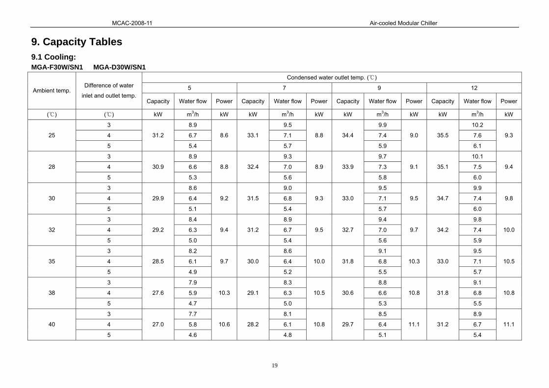
9. Capacity Tables 9.1 Cooling: MGA-F30W/SN1 MGA-D30W/SN1
Condensed water outlet temp. ( )
5 7 9 12 Ambient temp. Difference of water
inlet and outlet temp. Capacity Water flow Power Capacity Water flow Power Capacity Water flow Power Capacity Water flow Power
( ) ( ) kW m3/h kW kW m3/h kW kW m3/h kW kW m3/h kW
3 8.9 9.5 9.9 10.2
4 6.7 7.1 7.4 7.6 25
5
31.2
5.4
8.6 33.1
5.7
8.8 34.4
5.9
9.0 35.5
6.1
9.3
3 8.9 9.3 9.7 10.1
4 6.6 7.0 7.3 7.5 28
5
30.9
5.3
8.8 32.4
5.6
8.9 33.9
5.8
9.1 35.1
6.0
9.4
3 8.6 9.0 9.5 9.9
4 6.4 6.8 7.1 7.4 30
5
29.9
5.1
9.2 31.5
5.4
9.3 33.0
5.7
9.5 34.7
6.0
9.8
3 8.4 8.9 9.4 9.8
4 6.3 6.7 7.0 7.4 32
5
29.2
5.0
9.4 31.2
5.4
9.5 32.7
5.6
9.7 34.2
5.9
10.0
3 8.2 8.6 9.1 9.5
4 6.1 6.4 6.8 7.1 35
5
28.5
4.9
9.7 30.0
5.2
10.0 31.8
5.5
10.3 33.0
5.7
10.5
3 7.9 8.3 8.8 9.1
4 5.9 6.3 6.6 6.8 38
5
27.6
4.7
10.3 29.1
5.0
10.5 30.6
5.3
10.8 31.8
5.5
10.8
3 7.7 8.1 8.5 8.9
4 5.8 6.1 6.4 6.7 40
5
27.0
4.6
10.6 28.2
4.8
10.8 29.7
5.1
11.1 31.2
5.4
11.1

MCAC-2008-11 Air-cooled Modular Chiller
20
MGA-F65W/SN1 MGA-D65W/SN1 Condensed water outlet temp. ( )
5 7 9 12 Ambient temp. Difference of water
inlet and outlet temp. Capacity Water flow Power Capacity Water flow Power Capacity Water flow Power Capacity Water flow Power
( ) ( ) kW m3/h kW kW m3/h kW kW m3/h kW kW m3/h kW
3 19.4 20.6 21.4 22.0
4 14.5 15.4 16.0 16.5 25
5
67.6
11.6
18.6 71.7
12.3
19.1 74.5
12.8
19.5 76.9
13.2
20.0
3 19.2 20.1 21.1 21.8
4 14.4 15.1 15.8 16.3 28
5
67.0
11.5
19.1 70.2
12.1
19.3 73.5
12.6
19.7 76.1
13.1
20.4
3 18.5 19.6 20.5 21.5
4 13.9 14.7 15.4 16.1 30
5
64.7
11.1
19.9 68.3
11.7
20.0 71.5
12.3
20.5 75.1
12.9
21.1
3 18.1 19.4 20.3 21.2
4 13.6 14.5 15.2 15.9 32
5
63.3
10.9
20.4 67.6
11.6
20.6 70.9
12.2
21.0 74.1
12.7
21.7
3 17.7 18.6 19.7 20.5
4 13.3 14.0 14.8 15.4 35
5
61.8
10.6
21.0 65.0
11.2
21.5 68.9
11.8
22.3 71.5
12.3
22.8
3 17.1 18.1 19.0 19.7
4 12.9 13.6 14.3 14.8 38
5
59.8
10.3
22.3 63.1
10.8
22.8 66.3
11.4
23.4 68.9
11.8
23.4
3 16.8 17.5 18.4 19.4
4 12.6 13.1 13.8 14.5 40
5
58.5
10.1
23.0 61.1
10.5
23.4 64.4
11.1
24.1 67.6
11.6
24.1

MCAC-2008-11 Air-cooled Modular Chiller
21
9.2 Heating: MGA-F30W/SN1 MGA-D30W/SN1
Warm water outlet temp. ( )
39 42 45 48 50 Ambient
temp.
Difference
of water
inlet and
outlet
temp.
Capacity Water
flow Power Capacity
Water
flow Power Capacity
Water
flow Power Capacity
Water
flow Power Capacity
Water
flow Power
( ) ( ) kW m3/h kW kW m3/h kW kW m3/h kW kW m3/h kW kW m3/h kW
3 11.3 11.1 10.9 10.5 10.4
4 8.5 8.3 8.2 7.9 7.8 13
5
39.4
6.8
9.4 38.7
6.7
9.8 38.1
6.6
10.3 36.8
6.3
10.8 36.2
6.2
11.1
3 10.5 10.4 10.2 9.9 9.6
4 7.9 7.8 7.6 7.4 7.2 10
5
36.8
6.3
9.2 36.2
6.2
9.6 35.5
6.1
10.0 34.5
5.9
10.4 33.6
5.8
10.8
3 9.7 9.5 9.2 9.0 8.7
4 7.3 7.1 6.9 6.7 6.5 7
5
33.9
5.8
9.0 33.0
5.7
9.4 32.0
5.5
9.8 31.4
5.4
10.3 30.4
5.2
10.7
3 8.6 8.4 8.1 7.8 7.5
4 6.5 6.3 6.1 5.8 5.6 2
5
30.1
5.2
8.8 29.2
5.0
9.2 28.2
4.8
9.6 27.2
4.7
10.0 26.3
4.5
10.3
3 7.4 7.2 6.9 6.7 6.4
4 5.6 5.4 5.2 5.0 4.8 -2
5
25.9
4.5
8.5 25.0
4.3
8.9 24.0
4.1
9.4 23.4
4.0
9.8 22.4
3.9
10.2
3 6.4 6.2 6.0 5.8 5.5
4 4.8 4.7 4.5 4.3 4.1 -6
5
22.4
3.9
8.3 21.8
3.7
8.7 20.8
3.6
9.2 20.2
3.5
9.6 19.2
3.3
10.0
3 5.9 5.7 5.5 5.5 5.0
4 4.4 4.3 4.1 3.9 3.7 -10
5
20.5
3.5
8.1 19.9
3.4
8.5 19.2
3.3
9.0 18.3
3.1
9.4 17.3
3.0
9.8

MCAC-2008-11 Air-cooled Modular Chiller
22
MGA-F65W/SN1 MGA-D65W/SN1 Warm water outlet temp. ( )
39 42 45 48 50 Ambient
temp.
Difference
of water
inlet and
outlet
temp.
Capacity Water
flow Power Capacity
Water
flow Power Capacity
Water
flow Power Capacity
Water
flow Power Capacity
Water
flow Power
( ) ( ) kW m3/h kW kW m3/h kW kW m3/h kW kW m3/h kW kW m3/h kW
3 24.4 24.0 23.7 22.9 22.4
4 18.3 18.0 17.7 17.1 16.8 13
5
85.3
14.7
20.3 83.9
14.4
21.1 82.6
14.2
22.2 79.7
13.7
23.3 78.3
13.5
24.1
3 22.9 22.4 22.0 21.4 20.9
4 17.1 16.8 16.5 16.1 15.6 10
5
79.7
13.7
19.8 78.3
13.5
20.7 76.9
13.2
21.6 74.8
12.9
22.5 72.8
12.5
23.4
3 21.1 20.5 19.9 19.5 18.9
4 15.8 15.4 14.9 14.6 14.2 7
5
73.5
12.6
19.4 71.5
12.3
20.3 69.0
11.9
21.0 67.9
11.7
22.2 65.9
11.3
23.1
3 18.7 18.1 17.5 16.9 16.3
4 14.0 13.6 13.1 12.7 12.2 2
5
65.2
11.2
19.1 63.2
10.9
19.8 61.0
10.5
20.7 58.9
10.1
21.6 56.9
9.8
22.2
3 16.1 15.5 14.9 14.5 13.9
4 12.1 11.6 11.2 10.9 10.4 -2
5
56.1
9.6
18.4 54.1
9.3
19.2 52.0
8.9
20.3 50.6
8.7
21.1 48.5
8.3
22.0
3 13.9 13.5 12.9 12.5 11.9
4 10.4 10.1 9.7 9.4 8.9 -6
5
48.5
8.3
18.0 47.1
8.1
18.9 45.1
7.7
19.8 43.7
7.5
20.7 41.6
7.2
21.6
3 12.7 12.3 11.9 11.3 10.7
4 9.5 9.2 8.9 8.5 8.1 -10
5
44.4
7.6
17.8 43.0
7.4
18.4 41.6
7.2
19.4 39.5
6.8
20.3 37.5
6.4
21.1

MCAC-2008-11 Air-cooled Modular Chiller
23
10. Exploded View 10.1 MGA-F30W/SN1

MCAC-2008-11 Air-cooled Modular Chiller
24
No. Part Name Quantity No. Part Name Quantity 1 Top cover 1 30 Base ass'y 1 2 Axial flow fan 1 31 Suction pipe ass'y A 1 3 Motor 1 31.1 Pressure controller 1 4 Top cover 1 32 Suction pipe ass'y B 1 5 Motor bracket 2 32.1 Pressure controller 1 6 Rear cover 1 33 Accumulator cylinder 2 7 Side board 2 34 Middle partition plate 1 8 Side sealed board 4 35 Compressor 1 9 Front cover 1 36 Compressor 1 10 Cover board 2 37 Clapboard supporting board 3 11 Drainage pan 1 38 Condenser ass'y 1 12 Drainage pan holder 2 38.1 Temp sensor ass'y 1 13 Clamp 1 38.2 Temp sensor ass'y 3 14 Holder for Plate Heat-exchanger 1 39 Cover 1 15 Sealed board 1 40 E-part box ass'y 1 16 Cover 2 40.1 E-part box 1 17 Rear—front net 2 40.2 Transformer 1 18 Water Inlet/Outlet pipe ass'y 1 40.3 Main controller ass'y 1 19 Holder ring 2 40.4 Relay 2 20 Support board 2 40.5 Contactor 2 21 Cover 1 40.6 Compressor capacitor 1 22 4-way valve ass'y 1 40.7 Wire joint 1 22.1 Muffler 1 40.8 Wire joint 4 22.2 4-way valve 1 40.9 Wire joint 1 22.3 Pipe joint 2 40.10 Wire joint, 3p 1 22.4 Strainer 3 40.11 Wire joint, 4p 1 22.5 Pressure controller 1 41 E-Part box cover 1 22.7 Discharge temp sensor 1 43 Protecting water box 1 23 4-way valve ass'y 1 44 Sealed board ass'y 2 23.1 4-Ways valve solenoid 1 45 Condenser ass'y 1 23.2 Strainer 1 45.1 Temp sensor ass'y 3 23.3 Pressure controller 1 46 Motor holder 2 23.4 Muffler 1 47 Heat-exchanger ass'y 1 23.5 4-way valve 1 47.1 Electronic expansion valve 2 23.6 Pipe joint 3 47.2 Strainer 2 23.7 Discharge temp sensor 1 47.3 Plate Heat-exchanger 1 24 Bracket ass'y 2 47.4 EEV solenoid 2 25 Base ass'y 1 48 Sealed board ass'y 1 26 Bracket ass'y 2 49 Connecting pipe 1 27 Strengthen bracket 6 50 Connecting pipe ass'y 1 28 Base bracket 1 51 4-way valve connection pipe 1 29 Base bracket 1 52 R410A 3.5×2kg

MCAC-2008-11 Air-cooled Modular Chiller
25
10.2 MGA-F65W/SN1

MCAC-2008-11 Air-cooled Modular Chiller
26
No. Part Name Quantity No. Part Name Quantity1 Top cover 2 24 Base ass'y 2 2 Axial flow fan 2 25 Strengthen bracket 8 3 Motor 2 26 Compressor 4 4 Beam 1 27 Accumulator cylinder 4 5 Suction pipe ass'y B 2 28 Base bracket 1 5.1 Pressure controller 1 29 Base bracket 1 6 Suction pipe ass'y A 2 30 Clamp 2 6.1 Pressure controller 2 31 Holder for Plate Heat-exchanger 2 7 4-way valve ass'y 2 32 E-part box ass'y 2 7.1 Muffler 1 32.1 Main controller ass'y 2 7.2 4-way valve 1 32.2 Wire joint 8 7.3 Pipe joint 3 32.3 Wire joint 2 7.4 Strainer 1 32.4 Wire joint 2 7.5 Pressure controller 1 32.5 Transformer 2 7.6 EEV solenoid 1 32.6 Relay 4 7.7 Discharge temp sensor 1 32.7 Contactor 4 8 4-way valve ass'y 1 32.8 Compressor capacitor 2 8.1 Muffler 1 32.9 E-part box 2 8.2 4-way valve 1 33 Bracket ass'y 2 8.3 Pipe joint 1 34 Base ass'y 1 8.4 Strainer 1 35 Bracket ass'y 2 8.5 Pressure controller 1 36 Drainage pan holder 4 8.6 EEV solenoid 1 37 Connecting pipe ass'y 1 8.7 Discharge temp sensor 1 38 Connecting pipe 1 9 4-way valve ass'y 1 39 4-way valve connection pipe 1 9.1 EEV solenoid 1 40 Heat-exchanger plate 1 9.2 Strainer 1 40.1 Plate Heat-exchanger 1 9.3 Pressure controller 1 41 Heat-exchanger ass'y 1 9.4 Muffler 1 41.1 Electronic expansion valve 2 9.5 4-way valve 1 41.2 Strainer 2 9.6 Pipe joint 3 41.3 Plate Heat-exchanger 1 10 Clapboard supporting board 6 42 Middle partition plate 1 11 Motor bracket 4 43 Sealed board 1 12 Drainage pan 2 44 Water Inlet/Outlet pipe ass'y 1 13 Cover board 4 45 Holder ring 4 14 Side board 2 46 Side sealed board 4 15 Compressor cover bracket 2 47 Cover 2 16 Cover 2 48 Front cover 1 17 4-way valve connection pipe ass'y 1 49 Top cover 1 18 4-way valve connection pipe ass'y 1 50 Support board 4 19 Connecting pipe ass'y 1 51 Rear—front net 4 20 Connecting pipe ass'y 1 52 Sealed board ass'y 2 21 Protecting water box 2 53 Cover 4 22 Rear cover 1 54 Sealed board ass'y 1 23 E-Part box cover 2 55 Sealed board ass'y 1
MCAC-2008-11 Air-cooled Modular Chiller
27
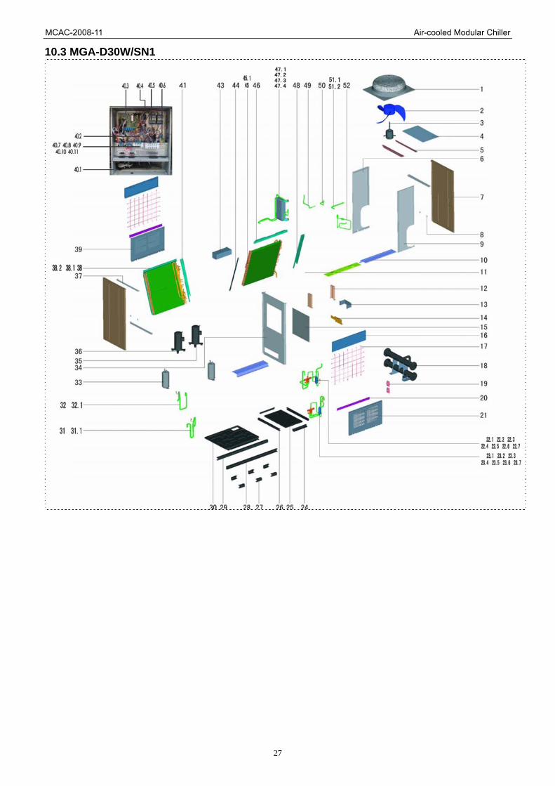
10.3 MGA-D30W/SN1
MCAC-2008-11 Air-cooled Modular Chiller
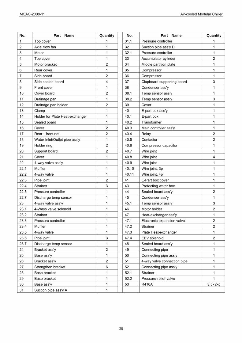
28
No. Part Name Quantity No. Part Name Quantity1 Top cover 1 31.1 Pressure controller 1 2 Axial flow fan 1 32 Suction pipe ass'y D 1 3 Motor 1 32.1 Pressure controller 1 4 Top cover 1 33 Accumulator cylinder 2 5 Motor bracket 2 34 Middle partition plate 1 6 Rear cover 1 35 Compressor 1 7 Side board 2 36 Compressor 1 8 Side sealed board 4 37 Clapboard supporting board 3 9 Front cover 1 38 Condenser ass'y 1 10 Cover board 2 38.1 Temp sensor ass'y 1 11 Drainage pan 1 38.2 Temp sensor ass'y 3 12 Drainage pan holder 2 39 Cover 1 13 Clamp 1 40 E-part box ass'y 1 14 Holder for Plate Heat-exchanger 1 40.1 E-part box 1 15 Sealed board 1 40.2 Transformer 1 16 Cover 2 40.3 Main controller ass'y 1 17 Rear—front net 2 40.4 Relay 2 18 Water Inlet/Outlet pipe ass'y 1 40.5 Contactor 2 19 Holder ring 2 40.6 Compressor capacitor 1 20 Support board 2 40.7 Wire joint 1 21 Cover 1 40.8 Wire joint 4 22 4-way valve ass'y 1 40.9 Wire joint 1 22.1 Muffler 1 40.10 Wire joint, 3p 1 22.2 4-way valve 1 40.11 Wire joint, 4p 1 22.3 Pipe joint 2 41 E-Part box cover 1 22.4 Strainer 3 43 Protecting water box 1 22.5 Pressure controller 1 44 Sealed board ass'y 2 22.7 Discharge temp sensor 1 45 Condenser ass'y 1 23 4-way valve ass'y 1 45.1 Temp sensor ass'y 3 23.1 4-Ways valve solenoid 1 46 Motor holder 2 23.2 Strainer 1 47 Heat-exchanger ass'y 1 23.3 Pressure controller 1 47.1 Electronic expansion valve 2 23.4 Muffler 1 47.2 Strainer 2 23.5 4-way valve 1 47.3 Plate Heat-exchanger 1 23.6 Pipe joint 3 47.4 EEV solenoid 2 23.7 Discharge temp sensor 1 48 Sealed board ass'y 1 24 Bracket ass'y 2 49 Connecting pipe 1 25 Base ass'y 1 50 Connecting pipe ass'y 1 26 Bracket ass'y 2 51 4-way valve connection pipe 1 27 Strengthen bracket 6 52 Connecting pipe ass'y 1 28 Base bracket 1 52.1 Strainer 1 29 Base bracket 1 52.2 Pressure-relief-valve 1 30 Base ass'y 1 53 R410A 3.5×2kg 31 Suction pipe ass'y A 1

MCAC-2008-11 Air-cooled Modular Chiller
29
10.4 MGA-D65W/SN1
No. Part Name Quantity No. Part Name Quantity1 Top cover 2 31 Accumulator cylinder 4 2 Axial flow fan 2 32 Base bracket 1 3 Motor 2 33 Base bracket 1 4 Beam 1 34 Clamp 2 5 Suction pipe ass'y B 1 35 Holder for Plate Heat-exchanger 2 5.1 Pressure controller 1 36 E-part box ass'y 2 6 Suction pipe ass'y A 2 36.1 Compressor capacitor 2 6.1 Pressure controller 1 36.2 Contactor 4 7 4-way valve ass'y 2 36.3 E-part box 2 7.1 Muffler 1 36.4 Transformer 2 7.2 4-way valve 1 36.5 Main controller ass'y 2 7.3 Pipe joint 3 36.6 Relay 4 7.4 Strainer 1 36.7 Wire joint 2 7.5 Pressure controller 1 36.8 Wire joint 8 7.6 EEV solenoid 1 36.9 Wire joint 2 7.7 Discharge temp sensor 1
36.10 Wire joint, 3p 1

MCAC-2008-11 Air-cooled Modular Chiller
30
8 4-way valve ass'y 1 36.11 Wire joint, 4p 1 8.1 Muffler 1 37 Bracket ass'y 2 8.2 4-way valve 1 38 Base ass'y 1 8.3 Pipe joint 3 39 Bracket ass'y 2 8.4 Strainer 1 40 Drainage pan holder 4 8.5 Pressure controller 1 41 Connecting pipe ass'y 1 8.6 EEV solenoid 1 42 Connecting pipe 1 8.7 Discharge temp sensor 1 43 4-way valve connection pipe 1 9 Suction pipe ass'y D 1 44 Heat-exchanger plate 1 9.1 Pressure controller 1 44.1 Plate Heat-exchanger 1 10 4-way valve ass'y 1 45 Heat-exchanger ass'y 1 10.1 4-Ways valve solenoid 1 45.1 Electronic expansion valve 2 10.2 Strainer 1 45.2 Strainer 2 10.3 Pressure controller 1 45.3 Plate Heat-exchanger 1 10.4 Muffler 1 46 Middle partition plate 1 10.5 4-way valve 1 47 Sealed board 1 10.6 Pipe joint 3 48 Water Inlet/Outlet pipe ass'y 1 10.7 EEV solenoid 1 49 Holder ring 4 10.8 Discharge temp sensor 1 50 Side sealed board 4 11 Clapboard supporting board 6 51 Cover 2 12 Motor bracket 4 52 Front cover 1 13 Drainage pan 2 53 Top cover 1 14 Cover board 4 54 Support board 4 15 Side board 2 55 Rear—front net 4 16 Compressor cover bracket 2 56 Sealed board ass'y 2 17 Cover 2 57 Cover 4 18 4-way valve connection pipe ass'y 1 58 Sealed board ass'y 1 19 4-way valve connection pipe ass'y 1 59 Sealed board ass'y 1 20 Connecting pipe ass'y 1 60 Condenser side board 1 21 Connecting pipe ass'y 1 61 Condenser side board ass'y 1 22 Connecting pipe ass'y 1 62 Motor holder 4 22.1 Strainer 1 63 Condenser ass'y 2 22.2 Pressure-relief-valve 1 63.1 Temp sensor ass'y 5 23 Protecting water box 2 63.2 Temp sensor ass'y 1 24 Rear cover 1 64 Condenser ass'y 2 25 E-Part box cover 2 64.1 Temp sensor ass'y 6 26 Base ass'y 1 64.2 Temp sensor ass'y 1 27 Strengthen bracket 8 65 Condenser Partition board ass'y 1 28 Compressor 1 66 Middle supporting board 2 29 Compressor 3 67 R410A 3.5×4Kg30 Base ass'y 1

MCAC-2008-11 Air-cooled Modular Chiller
31
11. Troubleshooting 11.1 Failure & Protection Codes of the Module
Code Trouble
E0 Water-flow check trouble(wire controller and control board must be restarted when the trouble is displayed for
the third time)
E1 Power phases sequence failure
E2 Communication failure
E3 Total outlet water Temperature sensor failure (available for main unit)
E4 Plate heat exchanger outlet water Temperature sensor failure
E5 Condenser A tube Temperature sensor failure
E6 Condenser B tube Temperature sensor failure
E7 Outdoor Temperature sensor failure
E8 System A compressor discharge gas Temperature sensor failure
E9 Water-flow check trouble(wire controller and control board can recover automatically when the trouble is
displayed for the first and second times
EA The number of auxiliary unit checked by main unit decrease(only for wire controller)
EB Prevent frostbite Temp. sensor of plate heat-exchanger A trouble
EC Wire controller can not search the modules on line
ED Data communication between wire controller and modules failure(only for wire controller)
EE Communication between wire controller and computer failure(only for wire controller)
EF Prevent frostbite Temp. sensor of plate heat-exchanger B trouble
P0 System A high-pressure protection or discharge gas Temperature protection
P1 System A low-pressure protection
P2 System B high-pressure protection or discharge gas Temperature protection
P3 System B low-pressure protection
P4 System A current protection
P5 System B current protection
P6 System A Condenser high-Temperature protection
P7 System B Condenser high-Temperature protection
P8 Digital compressor discharge Temperature protection, when it is above 125
Pb System anti-freeze protection
PC Gas discharge Temp. of digital compressor above 125 protection(only for wire controller)
PE Low-temperature protection of plate heat-exchanger
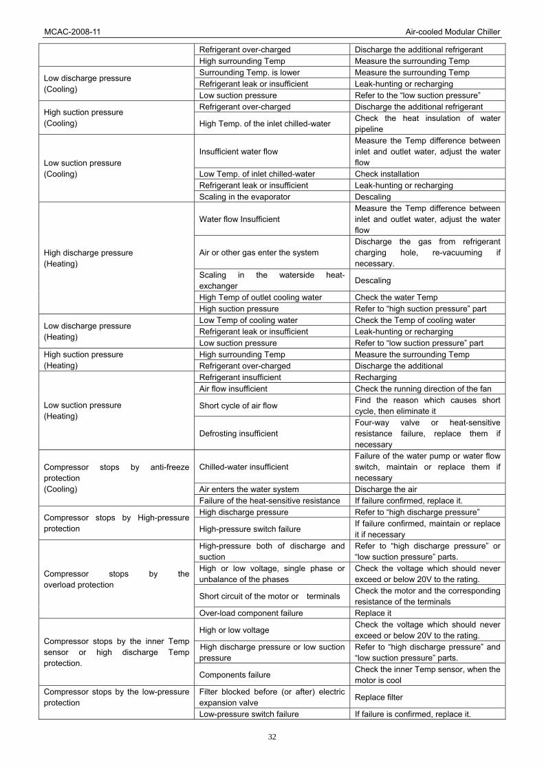
11.2 Troubles and Solutions Troubles Possible reasons Solutions
Air or other gas enter the system Discharge the gas from refrigerant charging hole, re-vacuuming if necessary
Fins are dirty or jammed by some obstacles
Splash the fins of condenser
The condenser wind flow is insufficient or motor fail
Check the condenser motor, repair it if necessary
High discharge pressure (Cooling)
High suction pressure Refer to the “high suction pressure” part.
MCAC-2008-11 Air-cooled Modular Chiller
32
Refrigerant over-charged Discharge the additional refrigerant High surrounding Temp Measure the surrounding Temp Surrounding Temp. is lower Measure the surrounding Temp Refrigerant leak or insufficient Leak-hunting or recharging
Low discharge pressure (Cooling)
Low suction pressure Refer to the “low suction pressure” Refrigerant over-charged Discharge the additional refrigerant
High suction pressure (Cooling) High Temp. of the inlet chilled-water
Check the heat insulation of water pipeline
Insufficient water flow Measure the Temp difference between inlet and outlet water, adjust the water flow
Low Temp. of inlet chilled-water Check installation Refrigerant leak or insufficient Leak-hunting or recharging
Low suction pressure (Cooling)
Scaling in the evaporator Descaling
Water flow Insufficient Measure the Temp difference between inlet and outlet water, adjust the water flow
Air or other gas enter the system Discharge the gas from refrigerant charging hole, re-vacuuming if necessary.
Scaling in the waterside heat- exchanger
Descaling
High Temp of outlet cooling water Check the water Temp
High discharge pressure (Heating)
High suction pressure Refer to “high suction pressure” part Low Temp of cooling water Check the Temp of cooling water Refrigerant leak or insufficient Leak-hunting or recharging
Low discharge pressure (Heating)
Low suction pressure Refer to “low suction pressure” part High surrounding Temp Measure the surrounding Temp High suction pressure
(Heating) Refrigerant over-charged Discharge the additional Refrigerant insufficient Recharging Air flow insufficient Check the running direction of the fan
Short cycle of air flow Find the reason which causes short cycle, then eliminate it
Low suction pressure (Heating)
Defrosting insufficient Four-way valve or heat-sensitive resistance failure, replace them if necessary
Chilled-water insufficient Failure of the water pump or water flow switch, maintain or replace them if necessary
Air enters the water system Discharge the air
Compressor stops by anti-freeze protection (Cooling)
Failure of the heat-sensitive resistance If failure confirmed, replace it. High discharge pressure Refer to “high discharge pressure”
Compressor stops by High-pressure protection High-pressure switch failure
If failure confirmed, maintain or replace it if necessary
High-pressure both of discharge and suction
Refer to “high discharge pressure” or “low suction pressure” parts.
High or low voltage, single phase or unbalance of the phases
Check the voltage which should never exceed or below 20V to the rating.
Short circuit of the motor or terminals Check the motor and the corresponding resistance of the terminals
Compressor stops by the overload protection
Over-load component failure Replace it
High or low voltage Check the voltage which should never exceed or below 20V to the rating.
High discharge pressure or low suction pressure
Refer to “high discharge pressure” and “low suction pressure” parts.
Compressor stops by the inner Temp sensor or high discharge Temp protection.
Components failure Check the inner Temp sensor, when the motor is cool
Filter blocked before (or after) electric expansion valve
Replace filter Compressor stops by the low-pressure protection
Low-pressure switch failure If failure is confirmed, replace it.
MCAC-2008-11 Air-cooled Modular Chiller
33
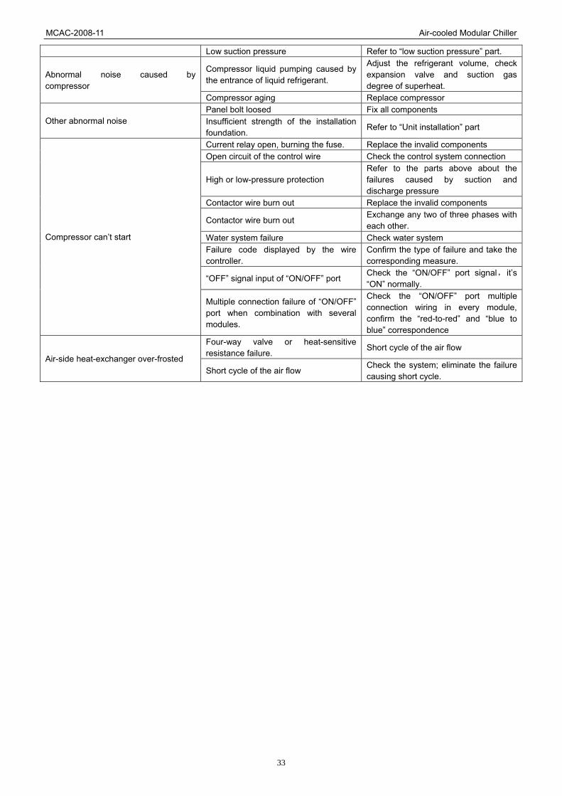
Low suction pressure Refer to “low suction pressure” part.
Compressor liquid pumping caused by the entrance of liquid refrigerant.
Adjust the refrigerant volume, check expansion valve and suction gas degree of superheat.
Abnormal noise caused by compressor
Compressor aging Replace compressor Panel bolt loosed Fix all components
Other abnormal noise Insufficient strength of the installation foundation.
Refer to “Unit installation” part
Current relay open, burning the fuse. Replace the invalid components Open circuit of the control wire Check the control system connection
High or low-pressure protection Refer to the parts above about the failures caused by suction and discharge pressure
Contactor wire burn out Replace the invalid components
Contactor wire burn out Exchange any two of three phases with each other.
Water system failure Check water system Failure code displayed by the wire controller.
Confirm the type of failure and take the corresponding measure.
“OFF” signal input of “ON/OFF” port Check the “ON/OFF” port signal, it’s “ON” normally.
Compressor can’t start
Multiple connection failure of “ON/OFF” port when combination with several modules.
Check the “ON/OFF” port multiple connection wiring in every module, confirm the “red-to-red” and “blue to blue” correspondence
Four-way valve or heat-sensitive resistance failure.
Short cycle of the air flow Air-side heat-exchanger over-frosted
Short cycle of the air flow Check the system; eliminate the failure causing short cycle.

MCAC-2008-11 Air-cooled Modular Chiller
34
12. Installation 12.1 Unit Installation 12.1.1 Transportation
Be sure that the package will be transported safely, unpack until reach installation site. The leaning angle during the transportation should be smaller than 15 degree to prevent the module
from rolling over. When transporting the module with rolling bars, it is recommended to use 6 bars under the module (4
bars with 30kW module), each one should be a bit longer than the width of basement to keep the module’s in balance.
30kW module 65kW module
Sling the module with steel wire, be sure that the wire could bear the weight 3 times heavier than that of the module, and check whether it hooks to module tightly. The hanging angle should be bigger than 60 degrees. Notice: it is absolutely forbidden to stand under the module while hanging, please use soft board to protect the module surface which contacts the steel wire from scratch and distortion.

MCAC-2008-11 Air-cooled Modular Chiller
35
12.1.2 Required installation place Clean, bright and well ventilated place such as roof, balcony or courtyard. Place without the interference of lampblack, steam and other kind of heat source. Place where it is convenient for piping and water drainage with the least influence to surroundings
caused by noise, cool or heat wind. Place close to electrical source for wiring. Place with solid basement preventing causing resonance and noise. Ensure there is sufficient space for the maintenance, the required room is as shown as follows, check
whether there are any barriers which would block the airflow. The wall around the module should be not higher than 1m (from the bottom of module).It is recommended to cover the module to prevent rain or snow, but the space between the cover and the top of module should be more than 2m.When parallel installing modules, it is suggested to leave sufficient space among modules for maintenance.
12.1.3 Installation Foundation
Before installation, structure and prefabrication of the basement should be seriously paid attention to, when installing on the top floor or middle, the floor intensity and noise prevention should be considered, it is referable to communicate with building designer before installation.
The drainage channel must be made around the basement which ensures the water can be drowning out fluently. In order to avoid the vibration and noise caused by module, a pad for reducing vibration must be set between the module and the basement, moreover, the module should be installed on the plane, and a shockproof basement can be adopted if it is necessary.
It is recommended to take some measures to strengthen fixing to prevent the movement caused by long-term running, earthquake or typhoon.
The installation basement for main module (just for reference) is shown as follows; the auxiliary module is the same as the main one. 60mm distance should be left between modules. The weight that the concrete can support should be 1.5 to 2 times more than the weight of modules when the modules are installed on the ground.

MCAC-2008-11 Air-cooled Modular Chiller
36
12.1.4 Operation Limits a. The range of voltage: Power supply: 380V 3ph 50Hz, the permitted max. Voltage: 418V, the permitted min. voltage: 342V. b. Temperature range for unit operation:
Cooling mode Heating mode Item
Model Ambient temperature Chilled water outlet Ambient temperature Heating water outlet
Heat pump 17 ~4 8 5 ~1 7 -10 ~ 21 45 ~5 0

MCAC-2008-11 Air-cooled Modular Chiller
37
12.2 Water System Installation Every pipeline’s joint has outlet and inlet mark. Please notice when connecting pipelines: Because the plate heat-exchanger has been used, the space for water passing is narrow, so it is easy
to be jammed by particulate, which may cause harmful freezing and damage the system. So it is strongly recommended to install a 20-item mesh net Y-shaped filter close to module-side chilled-water inlet (or cooling water) as much as possible.
Before connecting the water system to unit, it is necessary to clean the whole water pipeline and replace a new filter net, after ensuring that the water pipeline is clean, the connection can be done.
The soft connector should be used between the inlet (outlet) water pipeline and the unit to avoid vibration.
Turn on the water pump before unit starting, the water-flow switch should be installed on the water inlet pipeline before unit and connect pump’s wire to main module’s W1, W2 terminals.
Water-discharge switch must be installed on the outlet pipeline and the gas discharge valve on the inlet pipeline, the hand of the discharge switch must be taken away to prevent water shortage caused by wrong hand operation when unit is running.
The chilled-water pipeline should be covered with adequate heat insulated material to keep the Temp. of the water and prevent dewing.
In winter, if the unit is shut down, the water in the plate heat-exchanger and pipeline may freeze. To prevent freezing, it is absolutely forbidden to shut down the system (the system has the anti-freeze function) .If there is still be frozen, all the water in the system should be drained away, if it is difficult to drain the water, it is recommended to use some anti-freeze mixture such as glycol or propylene glycol.
Note: It is absolutely forbidden to use salt mixture, because it would corrode the system and cause damage.
There is no scale problem when using industrial standard water as chilled-water, on other hand, if the water from well or river is used, it may form much scale and sand. So it is necessary to pre-filter the water and intenerate by using relevant equipment before it enters the chilled-water system. If there is sand or mud in the evaporator, it will be blocked and cause freezing .So it is important to test the water’s PH value, conductivity, chlorine hydronium, sulfur hydronium etc. before used.
Note: For 30kW module ,each module consists of two units (two systems).They are system A,system B respectively from water-pipe
side; For 65kW module, each module consists of two units (four systems) and they are system A, system B (for main unit),
system A, system B (for auxiliary unit) respectively from water-pipe side.

MCAC-2008-11 Air-cooled Modular Chiller
38
Reference figure of water system installation
MCAC-2008-11 Air-cooled Modular Chiller
39
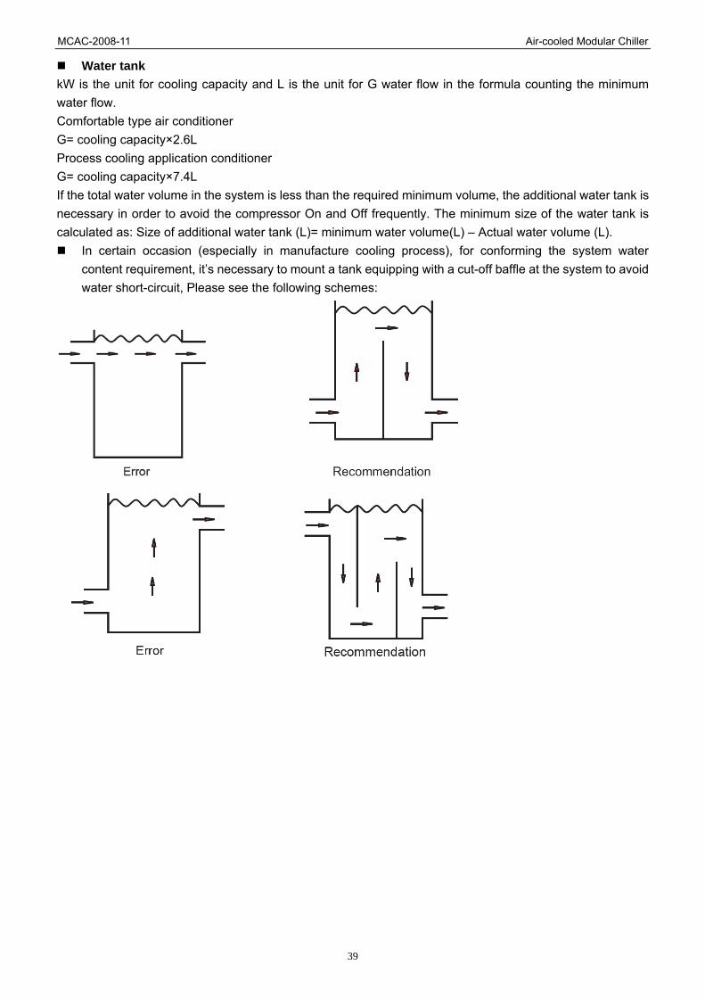
Water tank kW is the unit for cooling capacity and L is the unit for G water flow in the formula counting the minimum water flow. Comfortable type air conditioner G= cooling capacity×2.6L Process cooling application conditioner G= cooling capacity×7.4L If the total water volume in the system is less than the required minimum volume, the additional water tank is necessary in order to avoid the compressor On and Off frequently. The minimum size of the water tank is calculated as: Size of additional water tank (L)= minimum water volume(L) – Actual water volume (L).
In certain occasion (especially in manufacture cooling process), for conforming the system water content requirement, it’s necessary to mount a tank equipping with a cut-off baffle at the system to avoid water short-circuit, Please see the following schemes:

MCAC-2008-11 Air-cooled Modular Chiller
40
Water Quality The demanded quality of the water used by system is shown as follows: The freezing point and the boiling point of the glycol liquor(The consistency of glycol for preventing freezing)
poidometer 5 10 15 20 25 30 35 40 Liquor
Consistency% volumenometer 4.4 8.9 13.6 18.1 22.9 27.7 32.6 37.5
freezing point -1.4 -3.2 -5.4 -7.8 -10.7 -14.1 -17.9 -22.3
boiling point(100.7kpa) 100.6 101.1 101.7 102.2 103.3 104.4 105.0 105.6
The following is the standard of water quality:
PH value: 6.5~8.0 Total rigidity: <50ppm
Conductivity: <200μV/cm (25 ) Sulfur hydronium: None
Chlorine hydronium: <50ppm Ammonia hydronium: None
Vitriol hydronium: <50ppm Xi: <30ppm
Iron thickness <0.3ppm Natrium hydronium: None
Calcium hydronium: <50ppm
Relationship of water quality, furring and causticity
Water quality Furring Causticity Remark
1 PH≤6 acidic water Hard Big Hard CaSO4 will be built easily
2 PH≥8 acidic water Soft -------- Soft deposit with Fe3+&Cl- will be
made.
3 Water of Ca2+, Mg2+ Hard -------- Hard furring will be built easily.
4 Water of Cl- Dirt
resultant
Very
strong
Causticity will be very strong
special for iron and copper.
5 Water of SO42-, SiO2
2- Hard Big Hard CaSO4& CaSO2 will be built
easily
6 Water of Fe3+ Hard &
Dirt
l
Big Deposit of Fe(OH)3& Fe2O3
- will
be made.
7 Feculent water Dirt
resultant
Very
strong
Causticity will be very strong for
copper.
8 Organic compound of water Dirt
resultant -------- Furring will be built easily.
9 Water of exhaust gas -------- Big Copper pipe will be causticized
and perforated
10 Water of plastic dust Dirt
resultant -------- --------
11 Water of sulfurous acid gas in atmosphere -------- Very
strong --------
12 Water interfused by natural effects of pollution, for ex.
humidity nearby sea or hexapod body of garden belt
Dirt
resultant Big --------

MCAC-2008-11 Air-cooled Modular Chiller
41
Water flow switch installation reference 1. Water flow flake selecting Selecting flow flake should be according to the diameter of the water pipe at where the water switch installed. The length of flow flake should be a little short than the water pipe diameter. It cannot be too short, otherwise its action will be difficult when it gets the water current shocking. And it cannot be too long to get to the water pipe. 2. Installation sketch drawing
FLOW
FLOW
Water flow switch
Distance A must be 5 times than water pipe diameter
3. Wire sketch drawing of Water flow switch
Water flow decrease
Adjustableknob
Closedterminal OFF
Opendterminal ON
Commonterminal COM
Water flow increase
Adjustableknob
Disconnecting flow of water flow switch The disconnecting flow is 60% of system design flow. For example, there are 8 module units 65kw combined. The design flow is m and m=10.3×8=82.4, so if the disconnecting flow is m1, then m1=82.4×60%=49.4m3/h. Before adjusting the water flow switch, it should be confirmed whether the system is full of water and the air is almost exhausted totally. The adjusting should be carried on the condition that the main unit is off and only the water pump is working.
MCAC-2008-11 Air-cooled Modular Chiller
42
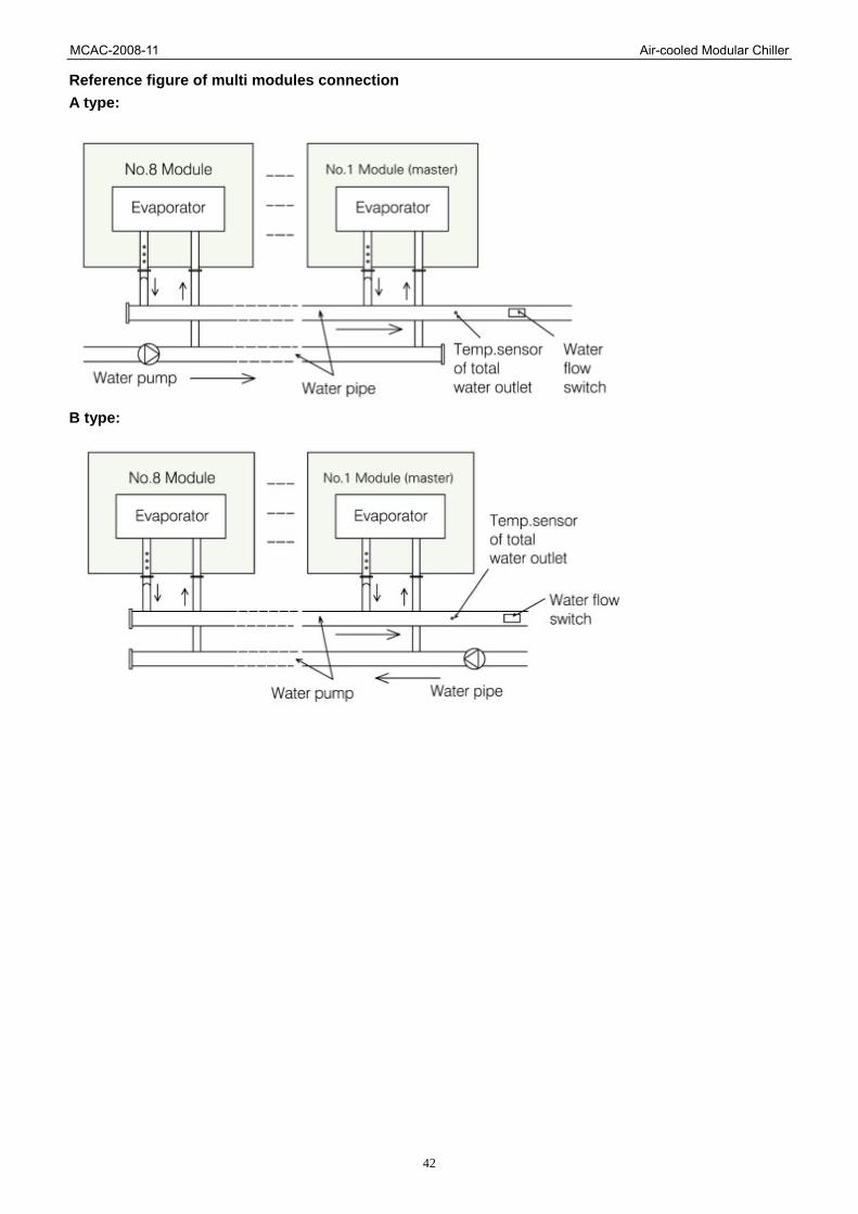
Reference figure of multi modules connection A type:
B type:

MCAC-2008-11 Air-cooled Modular Chiller
43
12.3 Wiring Installation All wiring installation should be done by qualified person. 12.3.1 Precautions: 1. The power supply must be stable when the unit is running. Considering all voltage-drop factors, the running voltage needed by the system should be kept within ±10% range of the rating. Too high or too low voltage will have bad effect on the unit. 2. The difference of voltage among phases should be not more than 2% of the rating, and the max current difference among phases should be less than 3% the rating to prevent compressor from overheating. 3. The frequency of the power should be kept within ±2%of the rating. 4. The lowest starting voltage should be more than 90% of the rating. 5. The compressor may be unable to start if the wire is too longer, so the length of the wire should be limited to ensure the voltage-drop between the two ends of the wire is less than 2% of the rating. If it is unavailable to shorten the wire, thicker wire is available. 6. All wire must conform to concerning national standards and well insulated. The insulation between terminals and modules should be checked by 500v high resistance meter and its insulation resistance should be not less than 10 MΩ. 7. For safety, according to the concerning standards, unit should be grounded well to prevent electric shock. 8. The running current, input power and other parameters on the nameplate might be different from the actual situation, which is decided by the actual load and cooling water temp., so it is recommended to select power source, transformer, fuse switch and the size of the wire in the consideration of the worst condition. 9. In order to control the compressors conveniently as well as independently and avoid the damage caused by the short circuit, it is necessary to equip the suitable no-fuse air switch for each inlet wire. 10. For 30KW & 65 KW, One module consists of two units, each unit’s main power should be wired independently and the detail is shown as follow:
The minimal diameter Of wire (mm2)
(metal tube, vinylite) Manual switch(A)
Items
Model Power
Power wire(<30m) Grounding Volume Fuse
Creepage
protector
30kW module
65kW module
380V 3N~
50Hz 10 10 50 36 100mA
11. Any part of wiring cannot be exposed when wiring is connected to the terminal. 12. Leak electric switch must be set in power supply system of every module unit. 13. The control signal wiring must use two-cores shielded twisted-pair(KVVP 1mm2 or RVVP 1mm2 ). Don’t use many-cores wiring (above 3 cores), otherwise the weak signal would be distributed, especially in the place with inverter equipments. 12.3.2 Wiring Specification 1. Category of common wiring.
Wiring model Description
RV Cooper core, PVC insulation, tabulate soft wiring
BVV Fix, lay, cooper core, PVC insulation, PVC jacket cable
RVV Cooper core, PVC insulation, PVC jacket, circular soft cable
RVVB Cooper core, PVC insulation, PVC jacket, tabulate soft cable
RVVP Cooper core, PVC insulation, PVC jacket, screened soft cable
KVV-C Cooper core, PVC insulation, PVC jacket, control cable
KVVP Cooper core, PVC insulation, PVC jacket, screened control cable

MCAC-2008-11 Air-cooled Modular Chiller
44
VV Cooper core, PVC insulation, PVC jacket, electric power cable
ZR-VV Anti-burning, Cooper core, PVC insulation, PVC jacket, electric power cable
YCW Heavy-duty, rubber-bushed, soft electric power cable
2. Specification of control wiring Description Length (m) Specification
Communication signal wiring
Wiring controller signal wiring ≤500m
KVVP-300/300 2×1.0mm2 or
RVVP-300/300 2×1.0mm2
Wiring controller power wiring ≤50m KVVP-300/500 3×1.5mm2
Remark: shield twisted-pair should be used for communication effect. 3. Diameter selection of grounding wiring 1). Minimum section area of insulative grounding wiring is 1.5mm2; 2). Minimum section area of exposed grounding wiring is 4mm2; 3). Maximum section area of grounding wiring is 50mm2; 4) Commonly, section area is as follow list:
Phase section area of power supply wiring (S) Grounding and protection wiring
S≤16 S
16<S≤35 16
S>35 S/2
4. Power wiring (1) Category selection of power wiring
Occasion Code Compression
resistance Description
Common VV 600V/1000V Cooper core, PVC insulation, PVC jacket, power cable
Anti-burn ZR-VV 600V/1000V Anti-burned, cooper core, PVC insulation, PVC jacket, power cable
Armored VV22 600V/1000V Armored, cooper core, PVC insulation, PVC jacket, power cable
Anti-oil & outdoors YCW 450V/750V Heavy-duty, rubber-bushed, soft electric power cable
(2) Diameter selection Modules 30kW & 65kW
Wiring (mm2)
≤20m Total Capacity (kW)
Diameter of Phase wiring Diameter of Zero wiring
30 10 6
60 10 6
90 25 10
120 35 16
150 50 25
180 70 35
210 95 50
240 95 50
MCAC-2008-11 Air-cooled Modular Chiller
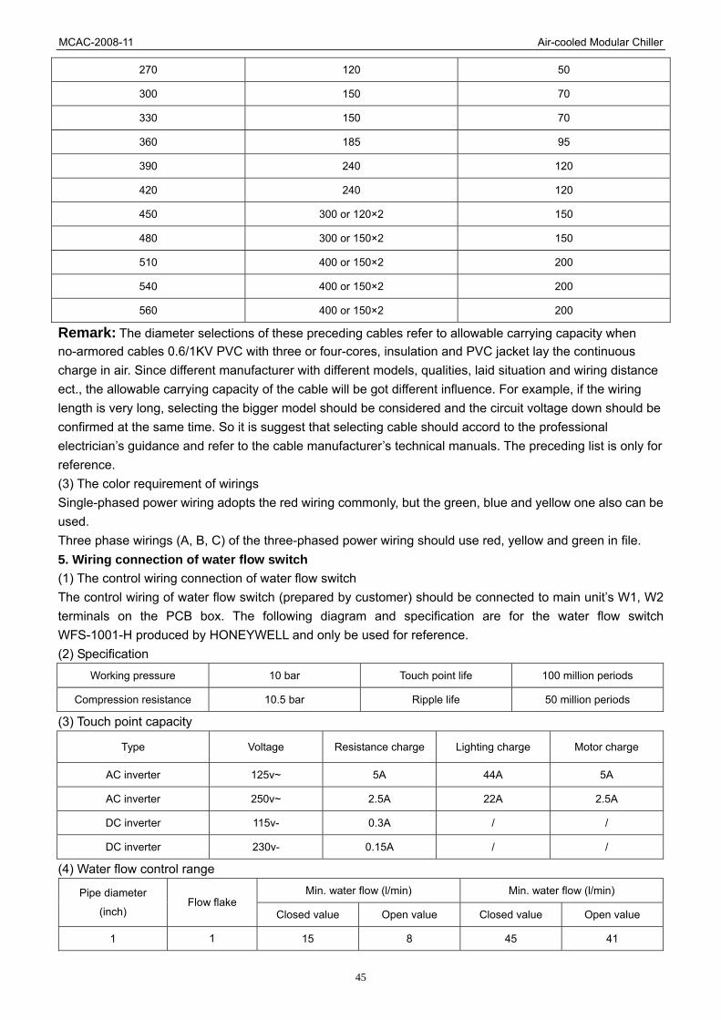
45
270 120 50
300 150 70
330 150 70
360 185 95
390 240 120
420 240 120
450 300 or 120×2 150
480 300 or 150×2 150
510 400 or 150×2 200
540 400 or 150×2 200
560 400 or 150×2 200
Remark: The diameter selections of these preceding cables refer to allowable carrying capacity when no-armored cables 0.6/1KV PVC with three or four-cores, insulation and PVC jacket lay the continuous charge in air. Since different manufacturer with different models, qualities, laid situation and wiring distance ect., the allowable carrying capacity of the cable will be got different influence. For example, if the wiring length is very long, selecting the bigger model should be considered and the circuit voltage down should be confirmed at the same time. So it is suggest that selecting cable should accord to the professional electrician’s guidance and refer to the cable manufacturer’s technical manuals. The preceding list is only for reference. (3) The color requirement of wirings Single-phased power wiring adopts the red wiring commonly, but the green, blue and yellow one also can be used. Three phase wirings (A, B, C) of the three-phased power wiring should use red, yellow and green in file. 5. Wiring connection of water flow switch (1) The control wiring connection of water flow switch The control wiring of water flow switch (prepared by customer) should be connected to main unit’s W1, W2 terminals on the PCB box. The following diagram and specification are for the water flow switch WFS-1001-H produced by HONEYWELL and only be used for reference. (2) Specification
Working pressure 10 bar Touch point life 100 million periods
Compression resistance 10.5 bar Ripple life 50 million periods
(3) Touch point capacity
Type Voltage Resistance charge Lighting charge Motor charge
AC inverter 125v~ 5A 44A 5A
AC inverter 250v~ 2.5A 22A 2.5A
DC inverter 115v- 0.3A / /
DC inverter 230v- 0.15A / /
(4) Water flow control range Min. water flow (l/min) Min. water flow (l/min) Pipe diameter
(inch) Flow flake
Closed value Open value Closed value Open value
1 1 15 8 45 41

MCAC-2008-11 Air-cooled Modular Chiller
46
1-1/4 26 13 75 68
1-1/2 29 20 105 94
2 34 17 120 105
2-1/2 60 34 210 188
3
2
68 30 288 275
4 128 64 412 360
5 225 113 750 652
6
3
345 172 1125 975
Note: Water flow switch can be installed outdoors without waterproof and horizontally or vertically. The buffer pipes must be installed in front of and behind water flow switch and its length should be 5 times of pipe diameter; since water flow switch cannot be got impact, so don’t install the fast closed valve at lower reaches of it. If cannot avoid such thing, should use the throttle to protecting it. 6. Auxiliary electric heater control wire connection (outfitting by users): The control wire of AC contactor must pass the main unit’s terminals H1, H2. The reference diagram is as follows:
7. Water pump control wire connection: the control wire of A/C contactor should through P1、P2 terminals of main unit as follows.
8. Wiring of “ON/OFF” weak electric port: first, corresponding parallel connect the “ON/OFF” port of each module’s electric control box (no more than 16) ,then, connect the “ON/OFF” signal (from the user’s timer) to the “ON/OFF” port of main unit as follows.

MCAC-2008-11 Air-cooled Modular Chiller
47
9. The module wiring and the installation wiring refer to the following:

MCAC-2008-11 Air-cooled Modular Chiller
48
Unit electric control & communication figure (for 30kW module)

MCAC-2008-11 Air-cooled Modular Chiller
49
Unit electric control & communication figure (for 65kW module)

MCAC-2008-11 Air-cooled Modular Chiller
50
Note: 1) Electrify unit 12 hours before starting to pre-heating the compressors, if it is not been done in advance,
the compressor may be damaged. 2) Regulate the water flow switch and the valve on the inlet pipeline carefully to ensure the water flow can
keep the 90% of the rating. 3) Check if the components of unit are loose. 4) Check if there is any problem of power supply or wiring before starting, especially phases sequence, if it
is incorrect, exchange any two of them with each other and ensure all the components are tightly connected.
5) Connect the water flow switch correctly to the control cycle. 6) Set tightly the Temp. Sensor to the corresponding site of unit.
13. Testing 1. Preparation After cleaning the water system pipeline for several times, ensure the water is clean, then pump and drain again, and start the pump to ensure the flow and the pressure of inlet and outlet pipeline is qualified. Notice: the water pump is under the control of the main unit, so when the water system is running, it can make the control circuit of water pump AC contactor electrify by temporarily wiring, thus to make the water pump running. Warning: it is absolutely forbidden to start the pump by the control of main unit before the water system has been adjusted well. 1) Please set the address switch on the module unit’s PCB according to the rule below. Warning: address switch setting must be done without any electric supply and when the unit is electrified, setting is absolutely forbidden.
Unit address setting Corresponding table between address code and unit address
0 presents NO. 0 main unit,1~F in turn presents NO
1~15 auxiliary units.(respectively)
One module consists of two units, so there are two
addresses for each module.
Address of each unit should not be repeated;
otherwise modules would be unable to start due to
protection. So it must set the switch to different address
code.
Address
code Unit address
0 NO. 0 main unit
1 NO. 1auxiliary unit
2 NO. 2 auxiliary unit
3 NO. 3 auxiliary unit
4 NO. 4 auxiliary unit
5 NO. 5 auxiliary unit
6 NO. 6 auxiliary unit
7 NO. 7 auxiliary unit
8 NO. 8 auxiliary unit
9 NO. 9 auxiliary unit
A NO. A auxiliary unit
B NO. B auxiliary unit
C NO. C auxiliary unit
D NO. D auxiliary unit
E NO. E auxiliary unit
F NO. F auxiliary unit
2) Digital scroll modular and Normal scroll modular can be selected according to DIGIT switch.

MCAC-2008-11 Air-cooled Modular Chiller
51
Notice: a. The DIGIT switch has been set well in the factory and needn’t change. b. Please turn on the main power 12 hours before staring to preheat the compressor. If the compressor is not preheated enough, it maybe damaged. 3) Adjust carefully the water flow switch on water system or close valve at inlet to ensure the water flow volume is 90% of the rating. 4) Check if any component of the unit is loose and the unit has no distortion and rupture. 5) Before starting, please check carefully if the power voltage and wiring are right. Check if the power sequence is correct. If not, it needs to exchange. Check if the connecting part is tight and fasten once again. 6) Connect the water flow switch correctly to the control cycle. 7) Put the Temp. Sensor to the right position, and then fasten it well to prevent from falling off. 2. Testing 1) Turn on the unit by wire controller. If there is ERROR Code displayed, please first eliminate the malfunction; confirm there is no malfunction before restarting. 2) After 30 minutes, when the temp of water is stable, adjust the water flow volume to nominal value to ensure the unit running normally. 3) When the unit is working, check the Running Current, Running Pressure, Water Pressure, Water flow Volume, Water Temp. Difference between inlet and outlet water, What’s more, adjust the water flow volume according to the actual conditions to ensure the unit running normally. The follow real values are reference: Ambient temp.=27 , Cooling condition
4) Optimizing the setting parameters according to the local weather and concerning operation references. 5) After the unit stops, start the unit 10 minutes later to prevent the unit from starting frequently. Check if the control and protection devices are normal according to the following table:
Models 30kW module and 65kW module
High-pressure switch
Cut off
Close
MPa
Reset automatically, unadjusted
4.4
3.2
For compressor Low-pressure switch
Cut off
Close
MPa
Reset automatically, unadjusted
0.15
0.3
“00” presents to select digital compressor (as the main unit.)
“11” presents to select constant compressor (as the auxiliary unit.)
System
Item
A system
(Digital)
A system
(Constant)
A system
(Constant)
A system
(Constant)
Compressor running current 6A 8A 8A 8A
Condenser temp. 39 38 38 37

MCAC-2008-11 Air-cooled Modular Chiller
52
Temp Sensor inside the digital
compressor -
Controlled by micro- controller
When the Temp. is lower than 125 , compressor will not work. When
the Temp. is higher than 125 , the capacity output of digital
compressor will decrease to 40%. When the Temp. is higher than
140 ,compressor will stop. After the malfunction disappears,
compressor will restart 3 minutes later.
Over-current protection A 18
Heating belt
Capacity W
Each compressor has one
40
Discharge Temp. Protection
Cut off
Close
130
90
Anti-freeze Protection
Switch
Controlled by micro- controller (one every cycle.)
3
Notices: 1. Because the water pump is under the control of main unit, it is forbidden to start the pump by the main unit when cleaning water system pipeline. 2. Before finishing draining water out from pipeline, it is forbidden to start unit. 3. Install the water flow switch correctly; otherwise water shortage accident will happen. 4. During test-running, do not restart the unit by manual in 4 minutes after the unit stops. 5. In the season when the unit needs to be frequently used, don’t switch off power after the unit stops. Otherwise, the compressor can’t be preheated, which may damage the compressor. 6. After a long time without electrifying, please pre-electrify the unit 12 hours in advance to preheat the compressors.

MCAC-2008-11 Air-cooled Modular Chiller
53
14. Maintenance To ensure the unit can reliably run for a long time, debugging and maintenance should be done by the qualified persons. The items below should be noticed especially. Warning: 1. If it is on fire, switch off the main power at once and eradicate the fire with extinguisher. 2. The unit can’t be operated near the flammable gas to prevent fire or explosion. Caution: 1. Maintain unit regularly according to the reference to keep unit in a good condition. 2. Do not touch the discharge pipeline to avoid any scald. 3. If malfunction causes the unit stop, please refer to the “Troubles and solutions” part of this manual or contact with us to find out the reason. After the malfunction is eliminated, the unit can be restarted again. It is absolutely forbidden to forced restart the unit without solving the problems. If refrigerant or chilled water (cooling water) has leakage, it must shut down all switches. If the unit can’t be stopped by the controller, it must switch off the main power to stop the unit. 4. Do not use any iron wire, copper wire instead of the demanded fuse, otherwise it will cause the fire and damage the system. 5. Don’t make the protection device short-circuited, otherwise it may cause accident. Maintenance for main components: 1. During running, please notice the discharge pressure and suction pressure. If there is anything abnormal, please find out the reason and eliminate the malfunction. 2. Don’t adjust the control and protection devices at random. 3. Check the wire connection regularly to confirm there is no any loose or bad contact caused by oxidation or other reasons. Please frequently check the work voltage, current and phases balance. 4. Check the reliability of the electric components, and replace the invalid and the unreliable in time. Descaling: After a long term running, the surface of the heat-exchanger of water side will form calcium oxide and other mineral. Those kinds of material will decrease the heat transfer efficiency, cause more power consumption and higher discharge pressure (or lower suction pressure). These materials can be cleaned by formyl, citric acid, vinegar acid, etc, but any liquid which contains chlorine acid or fluoride ingredient is forbidden. Because the pipe is made of stainless steel, it is easy to be rotted by such material. 1. Cleaning work of waterside heat exchanger should be operated by the professional, please contact with our local MIDEA service center. 2. After cleaning by chemical liquid detergent, scour the pipeline with clean water and heat the exchanger again. Pre-dispose the water to avoid rotting and forming of the scale again. 3. On the condition of using chemical liquid detergent, please select the intensity, cleaning time and Temperature of the liquid according to the actual situation. 4. After cleaning, the waste liquid should be neutralized, so please contact the professional company to get the further disposal for the waste. 5. Detergent and neutralization liquid are harmful to human beings, so it is necessary to use some protective device, such as special glasses, gloves, shoes, mask, etc. Turn off the unit in winter When turning off the units in winter, clean and dry the inner and outer surface of the unit, then cover them to prevent dust. Open the water discharge valve, drain away the water in heat exchanger of water side and water pipe to prevent freeze. It is recommended to inject some anti-freeze material into the water pipe. First start after the unit stops The following must be done when restarting the unit after a long-term vacancy: 1. Check and clean unit thoroughly. 2. Clean the water system pipeline. 3. Check water pump, adjust switch and other devices of the water system. 4. Tighten all the wire connections. Accessory replacement Only MIDEA accessory can be used and please don’t use any different one. Refrigeration system Check the discharge and suction pressure to determine whether the unit needs to recharge or not. Take leakage test for the system; if there is leakage or some components needs to be replaced, leakage test is necessary. When recharging refrigerant, two cases must be separated: 1. The refrigerant has leaked out totally
MCAC-2008-11 Air-cooled Modular Chiller
54
In this case, leakage test must be done by using nitrogen (15~20 kgf/cm2) or refrigerant. If necessary, welding should be done after all gas of the system is discharged out. 1) Connect the vacuum pump pipeline to the refrigerant charging hole. 2) Vacuum refrigerant pipeline more than 15 minutes and confirm it achieve -1.0×10⁵Pa (-76cmHg). 3) After having achieved the designated vacuity, add refrigerant to the system from the cylinder, corresponding volume of the refrigerant can be got from the nameplate and parameters table. It should be noticed that charging just be allowed from the liquid pipeline side. 4) The volume charged into the system will vary from different surrounding Temperature, if the designated volume can’t be achieved, unit can be started for recharging while the water system is running. Wire the low-pressure switch to short circuit if necessary. Notice: rewiring the connection after charging. 2. Additional refrigerant charge Connect refrigerant cylinder to the refrigerant charging hole and mount a pressure detector on the gas side pipeline. 1) Recycle the chilled-water, then start unit, take low-pressure control switch to short circuit if necessary. 2) Charge the refrigerant into the system slowly, and check the discharge and suction pressure. Warning: it is absolutely forbidden to charge the oxygen, acetylene or other gas which is poisonous or flammable into the system for leak hunting or leakage test, just nitrogen or refrigerant is allowed. Remove compressor If it is necessary to remove the compressor, please operate with the sequence below: 1) Switch off the power 2) Remove the electric wire 3) Remove the suction and discharge pipeline 4) Loosen the fixing bolts. 5) Remove the compressor. Auxiliary electric heater When the outdoor Temperature (is) below 0 , the condenser outside will frost, which will cause the heat transfer efficiency come down, for the reason above, when using unit in the areas where the lowest Temp is between -10~0 in the winter, it is recommended to select the auxiliary electric heat er to supply the additional heat. Select the heater with the reference of “Specification Table”, if the Temp below -10 , the higher power-input can be selected. System anti-freeze If plate heat exchanger is frozen, the exchanger will be damaged; in addition, this kind of damage is out of guarantee, so it should be specially noticed. Users should pay special attention to the three points below: 1. When there is a long-term vacancy with low outdoor Temp Water in waterside heat exchanger should be drained out if the Temp below 0 . 2. When running If the chilled-water flow switch and anti-freeze Temp Sensor are invalid, water pipeline will be frozen, so the wire of water flow switch must apply to the “wiring principle figure” 3. When maintaining It is possible to freeze waterside heat exchanger when recharging and discharging refrigerant. Whenever the pressure of the refrigerant is below 0.4Mpa, freezing would happen. So it is necessary to drained out all of the water or keeps the water flowing.

MCAC-2008-11 Air-cooled Modular Chiller
55
15. Control System 15.1 PCB Outline and Description 15.1.1 PCB, outlook view (30kW & 65kW module)
Notice: 1. Failure When main unit fails, the unit stops as well as the others stop too. When auxiliary unit fails, this unit stops while the others keep running. 2. Protection When main unit’s protection acts, the unit stops while the others keep running. When auxiliary unit’s protection acts, this unit stops while the others keep running. 15.1.2 Components description of 30kW & 65kW module
1——Compressor B current detection (Protection code P5) 2——Compressor A current detection (Protection code P4) The current will not be detected at the first 5 seconds when starting, after that, if the current is exceeds
the pre-set protection standard, (18A for both of digital and constant), compressor will stop, and restart 3 minutes later.
3——T4: Outdoor Temperature sensor (failure code E7).

MCAC-2008-11 Air-cooled Modular Chiller
56
T3B: Condenser B tube Temperature sensor (failure code E6, protection code P7). T3A: Condenser A tube Temperature sensor (failure code E5, protection code P6).
T4 If any one system needs to start the outdoor fan, the fan will be started by the unit electric controller. The fan has two speed levels: high and low which all depends on the T4 Temperature.
T3B、T3A When unit electric controller detects the Temperature of T3B or T3A are higher than 65 , the corresponding
system will stop, then restart after the Temperature is lower than 60 or less. Meanwhile the other system
keeps running without any influence. T4、T3B、T3A
The alarm will work if the voltage detected by the Temperature sensor is less than 0.05V or more than 4.95V. If main unit sensor of fails: all units will stop. If auxiliary unit sensor fails: this unit will stop while the others keep running.
4——System A compressor discharge gas Temperature sensor (failure code E8, protection code P8) is only available for main unit.
5——Outlet water Temperature sensor of plate heat exchanger (failure code E4). Capacity output will adjust according to the outlet water Temperature of the plate heat exchanger both in cooling and heating modes. (Auxiliary unit) constantly adjusting range: ON and OFF;
(Main unit) digitally adjusting range: Cooling mode: OFF, 30%, 40%, 50%, 60%, 70%, 80%, 90% and 100%. Heating mode: OFF, 30%, 40%, 50%, 60%, 70%, 80%, 90% and 100%.
6——Total outlet water Temperature sensor (failure code E3), just valid for main unit. Adjust the capacity output according to the outlet water Temperature of the plate heat exchanger both in cooling and heating modes
Adjusting range: OFF, 40%, 60%, 80%, and 100%. 7——CHECK. It can be achieved by CHECK to observe the running condition of the outdoor systems. The
corresponding data will be shown as follows:
A system running current
B compressor capacity
Running model
Normal display
Condenser A Temp.
Online modules
Ambient Temp.
Exv A liftExv B lift Condenser B 8——DIGIT Digital compressor selecting switch.
“00” presents selecting digital compressor (as the main unit.)
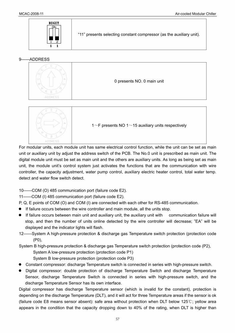
MCAC-2008-11 Air-cooled Modular Chiller
57
“11” presents selecting constant compressor (as the auxiliary unit).
9——ADDRESS
0 presents NO. 0 main unit
1~F presents NO 1~15 auxiliary units respectively
For modular units, each module unit has same electrical control function, while the unit can be set as main unit or auxiliary unit by adjust the address switch of the PCB. The No.0 unit is prescribed as main unit. The digital module unit must be set as main unit and the others are auxiliary units. As long as being set as main unit, the module unit’s control system just activates the functions that are the communication with wire controller, the capacity adjustment, water pump control, auxiliary electric heater control, total water temp. detect and water flow switch detect. 10——COM (O) 485 communication port (failure code E2). 11——COM (I) 485 communication port (failure code E2). P, Q, E points of COM (O) and COM (I) are connected with each other for RS-485 communication.
If failure occurs between the wire controller and main module, all the units stop. If failure occurs between main unit and auxiliary unit, the auxiliary unit with communication failure will
stop, and then the number of units online detected by the wire controller will decrease; ”EA” will be displayed and the indicator lights will flash.
12——System A high-pressure protection & discharge gas Temperature switch protection (protection code (P0),
System B high-pressure protection & discharge gas Temperature switch protection (protection code (P2), System A low-pressure protection (protection code P1) System B low-pressure protection (protection code P3)
Constant compressor: discharge Temperature switch is connected in series with high-pressure switch. Digital compressor: double protection of discharge Temperature Switch and discharge Temperature
Sensor, discharge Temperature Switch is connected in series with high-pressure switch, and the discharge Temperature Sensor has its own interface.
Digital compressor has discharge Temperature sensor (which is invalid for the constant), protection is depending on the discharge Temperature (DLT), and it will act for three Temperature areas if the sensor is ok (failure code E8 means sensor absent): safe area without protection when DLT below 125 ; yellow area
appears in the condition that the capacity dropping down to 40% of the rating, when DLT is higher than

MCAC-2008-11 Air-cooled Modular Chiller
58
125 for 10 minutes. If DLT is lower than 125 , protection will eliminate, on the other hand, if DLT keeps
increasing to 140 or more, it enter red area when the compressor stop and restart 3 minutes later if the problem has been solved. 13——Anti-frost protection sensor of plate exchanger T6, T62. 14——Water flow check (failure code E0 for main unit) which is just valid for main unit.
Main unit: main unit controller displays E9 when water flow is abnormal first time and second time and displays E0 when water flow is abnormal third time. (Display resumes after cutting power supply). Wire controller also displays E0 after three times’ checking.
Auxiliary: without water flow checking. 15——System B electric expansion valve. 16——System A electric expansion valve. EXV can adjust the refrigerant flow according to different running models and capacity requested by surrounding. 17——HEAT auxiliary heater. Notice: the actual figure of controller of the heater is not 220V power supply but ON/OFF switch! On heating mode, when the total outlet water temperature is below 45 , the switch closes and auxiliary
heater starts working; on the other hand, when the Temperature is above 50 , the switch opens to stop
heating and heater stops working. 18——WATER PUMP Notice: the actual figure of controller of the pump is not 220V power supply but ON/OFF switch!
Water pump will start at once after receiving the opening order and keep running during the whole running term of the system. Pump will close 2 minutes later after all the units having been shut down on cooling or heating mode.
Pump can be closed directly on the pump mode. 19——System B compressor
Ground wire System B four-way valve Ground wire
20——Digital tube On waiting mode: display unit address. On running mode: Main unit display the current capacity of the digital compressor as 40, 60, 80 and 10. (Notice “10” is
followed by “.”) Auxiliary unit display 10. (Notice “10” is followed by “.”) On failure or protection mode: display failure code or protection code.
21——System A compressor; Earth wire Four-way valve of system A Earth wire
22——High speed of outdoor fan, controlled by T4. 23——Low speed of outdoor fan, controlled by T4. 24——PWM, used for digital compressor capacity adjustment. (It is valid for main unit). 25——Transformer input, 220V/AC. 26——Power input by three-phase four-wire system (E1 for failure code). A, B, C phases should be supplied together with the 120 degree angle difference among three phases. If it is not qualified, it may cause phases sequence failure or phases absent failure then the corresponding code will be displayed until the power get right. Notice: phases sequence failure or phases absent failure are just
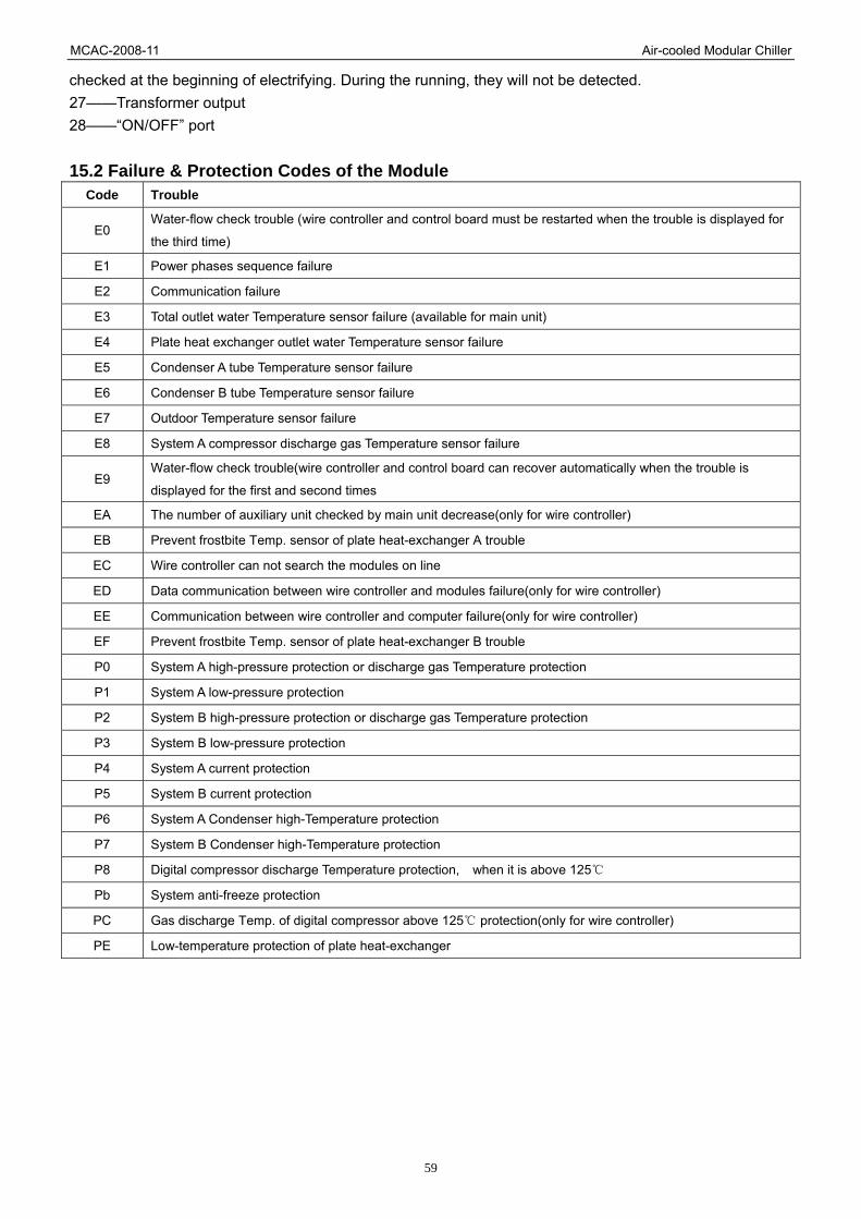
MCAC-2008-11 Air-cooled Modular Chiller
59
checked at the beginning of electrifying. During the running, they will not be detected. 27——Transformer output 28——“ON/OFF” port 15.2 Failure & Protection Codes of the Module
Code Trouble
E0 Water-flow check trouble (wire controller and control board must be restarted when the trouble is displayed for
the third time)
E1 Power phases sequence failure
E2 Communication failure
E3 Total outlet water Temperature sensor failure (available for main unit)
E4 Plate heat exchanger outlet water Temperature sensor failure
E5 Condenser A tube Temperature sensor failure
E6 Condenser B tube Temperature sensor failure
E7 Outdoor Temperature sensor failure
E8 System A compressor discharge gas Temperature sensor failure
E9 Water-flow check trouble(wire controller and control board can recover automatically when the trouble is
displayed for the first and second times
EA The number of auxiliary unit checked by main unit decrease(only for wire controller)
EB Prevent frostbite Temp. sensor of plate heat-exchanger A trouble
EC Wire controller can not search the modules on line
ED Data communication between wire controller and modules failure(only for wire controller)
EE Communication between wire controller and computer failure(only for wire controller)
EF Prevent frostbite Temp. sensor of plate heat-exchanger B trouble
P0 System A high-pressure protection or discharge gas Temperature protection
P1 System A low-pressure protection
P2 System B high-pressure protection or discharge gas Temperature protection
P3 System B low-pressure protection
P4 System A current protection
P5 System B current protection
P6 System A Condenser high-Temperature protection
P7 System B Condenser high-Temperature protection
P8 Digital compressor discharge Temperature protection, when it is above 125
Pb System anti-freeze protection
PC Gas discharge Temp. of digital compressor above 125 protection(only for wire controller)
PE Low-temperature protection of plate heat-exchanger

MCAC-2008-11 Air-cooled Modular Chiller
60
15.3 Controllers 15.3.1 Wired Controller: KJR-08B/BE:
Name of keys on the wired controller and the keypad operation description: 1. ON/OFF button: In the power off status, press this key and the startup indicator comes on, and the wire controller enters the startup status and keeps the current set information such as temperature value, timing. In the startup status, press this button once, and the startup indicator goes off and transmits the shutdown information. 2. Operation mode button: In the power off status, press this button to select the operation mode. This function is invalid at power on status. Modes shifted sequence as follows:
3. MANUAL/AUTO button Press this button; you could select [MANUAL/AUTO] these 2 modes. When select Manual mode, you could increase or decrease the online units via [PAGEUP/TEMP+] and [PAGEDOWN/TEMP-]. 4. QUERY button Press this button to query the status information of outdoor units 0~15(Outdoor unit 0 by default). After entering the query status, use [ADDRESS+] and [ADDRESS-] keys to query information of the previous or next outdoor unit. After selecting to query a specific outdoor unit, use the [PAGEDOWN/TEMP+] and [PAGEDOWN/TEMP-] keys to query the status information of this outdoor unit. The query sequence is: Outlet water temperature T1->Outdoor pipe temperature T3->Outdoor environment temperature T4->Setting temperature Ts->Current of compressor A and Current of compressor B -> Fault->Protection->Outlet water temperature T1.since there are many fault protection codes for the outdoor unit, the wire controller only displays the two fault protection messages with the highest priority when you check the fault protection information. 5. Heat button This button has no effect to KJR-08B/BE. 6 & 7 TIME ON/OFF button Every time when you press [TIME ON] button, the HOUR and MINUTE of timing startup blink at a frequency of 2Hz. They stop blinking when you adjust the hour and minute; and continue blinking 2 seconds after you stop adjustment. Press [TIME ON] key to select the timing HOUR for adjusting, and the timing hour blinks at frequency of 2Hz. Use the [PAGEUP/TEMP+] and [PAGEDOWN/TEMP-] keys to adjust the MINUTE. If you

MCAC-2008-11 Air-cooled Modular Chiller
61
keep idle without adjustment operation within 8 seconds after entering the timing setup status, the system will confirm the time setup and exit the timing setup status. Press [TIME OFF] key, as per the above method to set close time. Long press [TIME ON] button, you could cancel this function. Long press [TIME OFF] button, you could cancel this function. 8. TEMP SET button Setup the total water outlet temperature in cooling and heating mode. Setup tank or pool temperature in water heating mode. 9. OK button Once finished upon, press OK key, wire controller will delivery order to main unit. 10. ADDRESS+ button Press this button at Check mode; when select the next modular, the operation status of the next modular will display; if the current modular is 15# and the next one is 0#. Press this button for add address at wire address setting mode. If the wire controller address is 15, press this key will display the next address is 0. 11. ADDRESS- button Press this button at query mode; when select the previous modular, the operation status of the previous modular will display; if the current modular is 0# and the previous one is 15#. Press this button for minus address at wire address setting mode. If the wire controller address is 0, press this key will display the next address is 15. 12 & 13 PAGEUP/DOWN (TEMP+/-) button In manual mode, press these keys could add or minus the unit quantity. In the main page, press these keys could check the operation parameter of the unit. In temperature setting page, add or minus the temperature setting. In timing ON/OFF setting, press these keys to adjust the time of startup or closedown. 14. RESET button (Hidden) Use a 1mm-diameter round stick to press this button, and the current setting will be cancelled and the wire controller enters the reset status. 15. LOCK button (Hidden) Use a 1mm-diameter round bar to lock the current setting. Press this button again to unlock. 16. ADDRESS SET button (Hidden) The address of wire controller is set by press this button. The address range 0~15, therefore, 16 wire controller could be parallel at most. When there is only one wire controller, it is no necessary to execute this setting, because the address of wire controller has been set to '0'(main wire controller) in the factory.
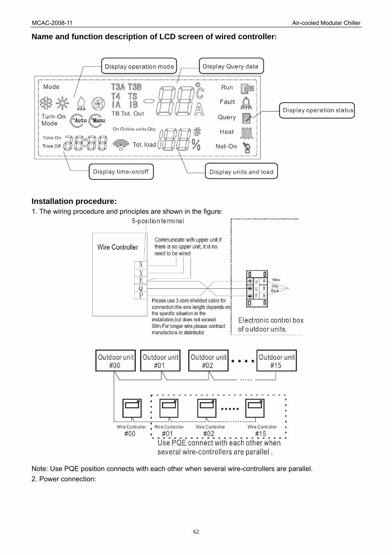
MCAC-2008-11 Air-cooled Modular Chiller
62
Name and function description of LCD screen of wired controller:
Installation procedure: 1. The wiring procedure and principles are shown in the figure:
Note: Use PQE position connects with each other when several wire-controllers are parallel. 2. Power connection:

MCAC-2008-11 Air-cooled Modular Chiller
63
Operation procedure of wired controller: 1. Press AUTO/MANUAL mode at shutdown status, you could select MANUAL or AUTO turn-on mode as you want. The function is invalid at startup status. In Manual mode, press [PAGEUP/TEMP+] or [PAGEDOWN/TEMP-] button for select your require online unit quantity. 2. Press [TEMP SET], [PAGEUP/TEMP +], [PAGEDOWN/TEMP -] button, for select your require temperature. For KJR-08B/BE: Cooling range:5~17 ; Heating range:45~50 . 3. Press [ON/OFF] button, running indicator of wire controller is light, unit is start to run, and display running status at wire controller. Press this button once again, unit will stop running. Operation procedure of Time ON 1. Press [TIME ON] button adjust your require time by [PAGEUP/TEMP+] or [PAGEDOWN/TEMP-] (MINUTE and HOUR could be shifted by this button). Use the same method to set Time off. (Note: Time ON/OFF is relative time.) Operation procedure of disable the function of Time ON/OFF. 1. Long press [TIME ON] button, you could cancel this function. Long press [TIME OFF] button, you could cancel this function.

MCAC-2008-11 Air-cooled Modular Chiller
64
Operation procedure of units information querying 1. Press [QUERY] entering Check status. 2. Press [ADDRESS+] or [ADDRESS-] button, select the unit you are wanted to query. 3. Press [PAGEUP/TEMP+)] or [PAGEDOWN/TEMP-] button to query the units information, which includes outdoor ambient temperature T4, pipe temperature T3, setting temperature Ts, CEB out water temp. TB, online quantity and compressor current, etc. Operation procedure of system information querying 1. Press [PAGEUP/TEMP+] or [PAGEDOWN/TEMP-] button in the main page, system information could be queried. Operation procedure of water temperature setting 1. Press [TEMP SET] button of wire controller when background light is on. 2. Press [PAGEUP/TEMP+] or [PAGEDOWN/TEMP-] button select your require water temperature. Once selected upon, temperature value will blinks a couple of seconds then confirm it. 3. KJR-08B/BE temperature range: Cooling: 5~17 Heating: 45~50 Fault alarm handing When unit fails or the wire controller detects failure of communication with the outdoor units, the indicator blinks. After all faults of the system and the wire controller are eliminated, the indicator stops blinking. The fault indicator and the operation indicator share the same LCD.

MCAC-2008-11 Air-cooled Modular Chiller
65
15.3.2 CCM10 LCD Touch Screen (optional) It can control 8 units, 16 compressors. Control function as Query/Mode setting/Lock/Weekly timer setting/Power failure memory.
Mechanical installation LCD touch screen normally installed in the casing of unit or the front board of console. Before installation, you should drill a mounting hole at unit casing or the front board of console firstly; and then, the thickness of the front not exceeds than 6mm; thirdly, LCD touch screen cannot be drilled. See following figure for outline dimension of the screen and size of drilled hole.
For guarantee the defective-proof level of the front board maintains at IP65, when installing you should install a gasket correctly as following processes: Mount LCD into mounting hole from forehead of the casing or console. Fix LCD up and ensure it would not fall down. Insert the attached hooks to corresponding flutes of LCD. Flutes sites are arrowed as following figure.
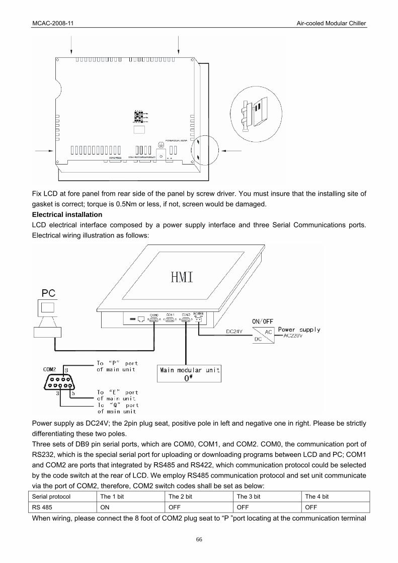
MCAC-2008-11 Air-cooled Modular Chiller
66
Fix LCD at fore panel from rear side of the panel by screw driver. You must insure that the installing site of gasket is correct; torque is 0.5Nm or less, if not, screen would be damaged. Electrical installation LCD electrical interface composed by a power supply interface and three Serial Communications ports. Electrical wiring illustration as follows:
Power supply as DC24V; the 2pin plug seat, positive pole in left and negative one in right. Please be strictly differentiating these two poles. Three sets of DB9 pin serial ports, which are COM0, COM1, and COM2. COM0, the communication port of RS232, which is the special serial port for uploading or downloading programs between LCD and PC; COM1 and COM2 are ports that integrated by RS485 and RS422, which communication protocol could be selected by the code switch at the rear of LCD. We employ RS485 communication protocol and set unit communicate via the port of COM2, therefore, COM2 switch codes shall be set as below: Serial protocol The 1 bit The 2 bit The 3 bit The 4 bit
RS 485 ON OFF OFF OFF
When wiring, please connect the 8 foot of COM2 plug seat to “P ”port locating at the communication terminal
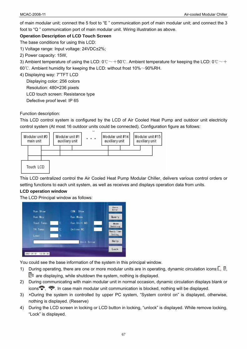
MCAC-2008-11 Air-cooled Modular Chiller
67
of main modular unit; connect the 5 foot to “E ” communication port of main modular unit; and connect the 3 foot to “Q ” communication port of main modular unit. Wiring illustration as above. Operation Description of LCD Touch Screen The base conditions for using this LCD: 1) Voltage range: Input voltage: 24VDC±2%; 2) Power capacity: 15W, 3) Ambient temperature of using the LCD: 0~+50 . Ambient temperature for keeping the LCD: 0 ~+
60 . Ambient humidity for keeping the LCD: without frost 10% ~90%RH. 4) Displaying way: 7”TFT LCD
Displaying color: 256 colors Resolution: 480×236 pixels LCD touch screen: Resistance type Defective proof level: IP 65
Function description: This LCD control system is configured by the LCD of Air Cooled Heat Pump and outdoor unit electricity control system (At most 16 outdoor units could be connected). Configuration figure as follows:
This LCD centralized control the Air Cooled Heat Pump Modular Chiller, delivers various control orders or setting functions to each unit system, as well as receives and displays operation data from units. LCD operation window The LCD Principal window as follows:
You could see the base information of the system in this principal window. 1) During operating, there are one or more modular units are in operating, dynamic circulation icons: , ,
are displaying, while shutdown the system, nothing is displayed. 2) During communicating with main modular unit in normal occasion, dynamic circulation displays blank or
icons , . In case main modular unit communication is blocked, nothing will be displayed. 3) ×During the system in controlled by upper PC system, “System control on” is displayed, otherwise,
nothing is displayed. (Reserve) 4) During the LCD screen in locking or LCD button in locking, “unlock” is displayed. While remove locking,
“Lock” is displayed.

MCAC-2008-11 Air-cooled Modular Chiller
68
Query window Click “query”, access to the following window:
In this page, you can query the information from unit No.0 to No.15. On-line units’ number shows in light blue, while out-line units' number shows in gray. Page 1 of Query Window: Press a certain on-line units' number, the following window shows and relevant parameters of the units system could be queried.
Page 2 of Query Window: Press “Next FG.” button, the other information of this unit group can be queried.
Press “Next unit” or “Previous unit” can query its neighbor unit's information. LCD setting window. Press “Mode setting” in principal window, the following window is entered.

MCAC-2008-11 Air-cooled Modular Chiller
69
At this page, you could select Operation Mode and Control Mode, adjust temperature and set Power Failure Memory. Temperature setting range: Cooling 7 ~12 , Heating 45 ~50 . Malfunction queried window: Press “Check Error” button at Query window or press “Check Error record” in principal window accessing to following window:
Malfunction occurring time and detail contents could be queried in this page. Click the malfunction in the form, and then click “Help” button, simple troubleshoot methods will be showed for user reference. Error history window In the page 1 of error history window, click “Check history record” button get in following window:
In this page, the ever occurred malfunctions and occurring times would be showed, however, once power failure, the malfunctions records would vanish. Weekly timer setting window: In this page, click “Weekly timer set” enters into following window:

MCAC-2008-11 Air-cooled Modular Chiller
70
In this window, there are seven timing segments from “Time_set1” to “Time_set 7” for your setting. Click a timing segment, and then click “Setting”, enter to this time parameter setting, window as follows:
Electricity control function description LCD operation description Query function Click “Query” button at principal window, and then enter to query window. The address codes of on-line units will show in this page in light blue. Click a light blue button, the page 1 of query window will be entered, click “Main FG” back to principal window. At the page 1 of “Query window”, click “Next Fig” could enter to other parameters setting pages; click “Next unit” or “Previous unit” could shift on-line units, click “Return” back to principal window; click“ Check Error” or “Check Error record” button enter to malfunction query window, in which, you could check the detail of the malfunction, additionally, increase or decrease the units number's value could skips among the different units whose malfunctions could be showed. Selected a malfunction, and click “Help”, system will enter into troubleshoot window providing some malfunction remove methods for user. Click “Return” back to previous window. Mode setting function Click “Mode setting” in the principal window enter to Mode Setting window. Click “Run Way change” realizing the transition between Manual Control Mode and Auto Control Mode. When switch to “Auto” mode, run unit quantity will be shielded, i.e. in this mode, system will automatically deicide the operating unit quantity as per capacity requirement, and drive up unit sequential according to their address from small to large. When switch to “Manual” mode, you should input the quantity to “Run unit” (Such value cannot larger than actual connected unit's quantity within the system.) If the system already in operating, any set are unavailable, but shutdown, because operation cannot be changed during operating. If the system in close-down, press the “Mode set” button, the mode would be changed once a time, the mode changed sequence as follows:

MCAC-2008-11 Air-cooled Modular Chiller
71
Under cooling mode operation, click temperature decreasing key to decrease temperature, once a degree, default temperature is 7 . Cooling adjusted temperature range is 7 ~12 Under heating mode operation, click temperature increasing key to increase temperature, once a degree, default temperature is 45 . Heating adjusted temperature range is 45 ~50 Under water pump mode, temperature adjusted keys will be shielded. In this page, you could query or return to previous page. Locking function If the LCD touch screen without be locked by upper PC or by keys, “Lock” is display in the upper left in the screen, click “Lock” then will be noticed to input user's name and password, after that, screen will be locked, “Unlock” is display. If the LCD touch screen be locked by upper PC or by keys, “Unlock” is display in the upper left in the screen, click “Unlock”, the screen is unlocked, “Lock” is display. When LCD or key is locked, all functions operations are invalid, but Query, System Setting and Help functions are excepted. Run/Stop button At Mode Setting window, Stop button is available when unit operating, while Run button that shielded by Shielded Mode will unavailable though be shifted. Run button is available when unit standbying, all buttons are available but Stop button. Unit is closed down when system in operating, and it will run according to last mode (Includes operation mode and manual/auto control mode) till to the next start-up, but the start-up mode or control mode have been reset. Run/Stop button are available in anytime. Every time you press this key, which is unavailable at once until the operation order have been sent out (cost no more than 5 seconds). Temp. Set button After setting up “Temp. Set” at heating or cooling mode, press “Set” button to confirm the finish of temperature setting. Communicate with unit group Provided that LCD without receive data from main modular unit last than10 seconds, that means main modular unit communication malfunction is occur, and “Equipment communication have blocked” is displayed in the screen. Malfunction could be removed when communication is recovery. If communication data error occurs in main modular unit or auxiliary unit, which means communication malfunction between LCD and modular unit is come out, error code “ED” shows, which could be removed when communication is recovered. Communicate with upper PC (Reserve) LCD in receiving status at normal occasion, waiting for receives data from upper PC. If LCD receives data from upper PC, unit is in network controlling, “Network control ON” displays. If no signal receives from upper PC last than 1 second that means unit exit from network controlling and “Network control ON” disappear. If frame error or data verified error comes out during data communication that means communication malfunction between LCD and PC is put out, code “EE” shows, it will recovery after malfunction be removed.

MCAC-2008-11 Air-cooled Modular Chiller
72
Operation mode and control mode setting Select “Mode Setting” window by the key in principal window, and then select “Run Way” and required “Run Unit” quantity in the mode setting window. 1) When “Auto” control mode is selected, operation mode and control mode in there are stand for the
modes of whole unit group system, thus you don't need to selected the” Run Unit” quantity that has been defined as the actual on-line unit quantity. The actual operating unit quantity is decided by electricity control of main modular unit.
2) When “Manual” control mode is selected, such operation mode and control mode are stand for the current selected unit, and “Run Unit” quantity could be altered. Once click “Run Unit”, actual operating unit quantity is decided by LCD. Units will be driven up sequential according to their address from small to large till to the set quantity is satisfied. While they will close off sequential according to their address from large to small till to the set quantity is satisfied.
3) Only the pump in main modular unit will open, when open Pump Mode at manual control mode. Main modular unit cannot be taken place of another, provided that malfunction is come out from it.
Malfunction alarm disposing In case protection or malfunction comes out, the corresponding malfunction unit's number will display in the principal window. User could check malfunction detail via Query Function. In case main modular unit come out of malfunction, all units within this modular would close down according to their address code value from large to small. Unit will return to work in normal when restarted by main modular unit or LCD until malfunction has been settled out. Power failure memory
You could select this function manually in LCD. When this function is shielded, system will not read and save parameters.
The set parameters in memorizer. (Operation Mode: Cooling or Heating or Pump mode; Run Way: Manual or Auto mode; Temperature setting; Run/Stop: Unit Run or Unit Stop; Lock or Unlock, etc.) When power be input at the first time, reading of set parameter as zero.
Once open the power failure memory function, memorizer will record the latest parameter setting, through is different from previous setting.
Timing ON/OFF function Time parameters in this function are take the time displayed in LCD as a standard, applying weekly timer to realize. There are seven time segments for your selection in Time Setting window, from time_1 to time_7, and there are 9 parameters needed to be set under each segment, which are: Device=1(Keep default as 1,don't alter it.) Week=0(User could input 0~7, 1~7 are represent from Mon. to Sun., 0 stand for everyday) Enabled=0(1 stand for weekly timer is available, 0 stand for weekly timer is unavailable) Time=00:00(User could input anytime from 00:00 to 24:00) Run Way=0(0 stand for Auto, 1 stand for Manual) Temp. Set=0(Cooling temperature from 7 ~12 , Heating temperature from 45 ~50 ) Run Unit=0(At manual control mode, operating unit quantity shall not be chosen exceeding than on-line unit quantity, otherwise, system run abnormally or auto mode inefficiency) Mode Set=0(1 stand for Cooling mode, 2 stand for Heating mode and 3 Stand for Pump mode; Shutdown the unit shall be set as 0.) On Off Set=0(0 stand for shut-down, 2 stand for start-up)