mccook main tunnel system connection to tarp mainstream tunnel on right chicago tunneling overview...
TRANSCRIPT

CHICAGO TUNNELING OVERVIEW & RESERVOIRS CONNECTING TUNNELS
Faruk Oksuz, P.E. & Cary Hirner, P.E.
McCook Main Tunnel System connection to TARP Mainstream Tunnel on right

Welcome to Chicago
• Windy City
• Lake Front Attractions
• Museum Campus - Art Institute
• Navy Pier
• Maggie Daley Park / Grant Park
• Michigan Avenue
• Cubs Game
• Choose CTA Blue Line into the City, and CTA Red Line to Wrigley Field
• McCook Reservoir & Tunnel Project Visit on Thursday, August 17

Chicago Tunneling Overview
• A True Tunneling Town
• Tunneling Geology
• Tunneling Aspects Unique to Chicago
• TARP McCook Reservoir Connection
• TARP Thornton Composite Reservoir Thorn Creek Diversion Tunnel Connection
• Q & A
Chicago has more tunnels than most other cities in the world. Flat topography and favorable ground conditions inspired tunnels to be built and utilized since 1866 with Lake Michigan Water Intake. In 1899, the Illinois Telephone and Telegraph Company secretly built the first utility and railway tunnel (Chicago Tribune).

Chicago Tunnels
• 1899 to 1933 - Nearly 60 miles of freight/utility tunnels - about 45 miles is still in use for utilities -power, gas, cable, fiber optic, data, etc.
• City of Chicago, Water Tunnels since 1866
• CTA’s transit tunnels
• 550 miles of MWRD interceptors with tunnels
• 1972 to 2006 – 110 miles of tunnels for TARP, ranging from 8 to 33-ft in diameter
• Miles & miles of more other raw water and sewer, stormwater tunnels
Over 300 miles of large (>8-ft) diameter tunnels in and around the City
MWRD Thorn Creek Diversion Tunnel , a 22-foot, unlined hard rock TBM tunnel excavated by Jay Dee for flood water diversions into Thornton Transitional Reservoir in early 2000, and later lined with concrete by Walsh in 2014.

Tunnels are Long-Term & Sustainable Solutions
• Tunnels have been serving Chicagoland with a 100-year plus service life
• Benefits of shortest distance to get from point A to B, and without interfering with rivers, roadways, railways, and utilities
• Gravity conveyance benefits are maximized -no pumping or energy needed to operate except terminus pump stations
• Chicago’s below ground and “forgotten” marvels until the famous Chicago Tunnel Flood in 1992
Tunnels are very integral part of the water supply and environmental protection for Chicagoland’s 14 million population, including residential, commercial, and industrial users.

There are so many tunnels in Chicago
• Over the past 130 years, tunnels were built for water, coal freight, railways, utilities, river/railroad/roadway crossings, sewer, combined sewer overflows and flood management
• Tunnels have been a significant, and surely the most reliable and sustainable fabric of “Chicago’s Urban Living”
• Flat topography and ground conditions favorable for tunneling – hardpan/blue clay soils and Silurian Dolomite
• Water/wastewater infrastructure, Lake Michigan, and environmental protection - nowhere for water to run
• Dense and compact urban setting
• Maybe the Windy City folks are seeking shelter from cold weather, too
Chicago Tribune, Tempo, August 2, 2007 – P. T. Reardon

1860 1870 1880 1890 1900 1910 1920 1930 1940 1950 1960 1970 1980 1990 2000 2010 2020
Chicago Discovered and Built Tunnels Since 1860s…
All resulted in best tunnel engineering and construction experience / projects
1866Lake Michigan Water Intake
1869River Crossings
1906Freight Tunnels
1943Subways
2004FermiLab Physics Tunnels
1985 - 2006TARP Phase I
2006 - 2017TARP Phase II(Reservoir Connections)
1899Utility/Railway Tunnels
1950Interceptors

2020 2025 2030 2035 …. ….
Future is also Looking Bright for Tunnels in Chicago
Tunnels continue to prove to be the most effective urban solutions, particularly for flood and CSO management
2020 – 2025 ?Downtown - O’Hare Airport Hyperloop Tunnel ?
2018 -MWRD, City of Chicago, Evanston - Water, Flood Management, CSO Tunnels
2020 - ?FermiLab Accelerator Physics Tunnels
2025 - ?Rail Tunnel Upgrades & New Ones

Tunneling Geology of Chicago Area
9

General Stratigraphy of the Chicago Area
William H.B., Geology of the Chicago Area, ISGS, 1971. 10
Major Geologic Formations Tunneling Aspects
Glacial Till Freight tunnels, rail tunnels, water and sewer tunnels, utility tunnels
Silurian Limestone/ Dolomite
TARP tunnels, water and sewer and utility crossing tunnels.
Maquoketa Shale Not used - limited underground aggregate mining and physics tunnels penetrate through
Galena Dolomite Underground aggregate mining
St. Peter Sandstone No tunnels or mining
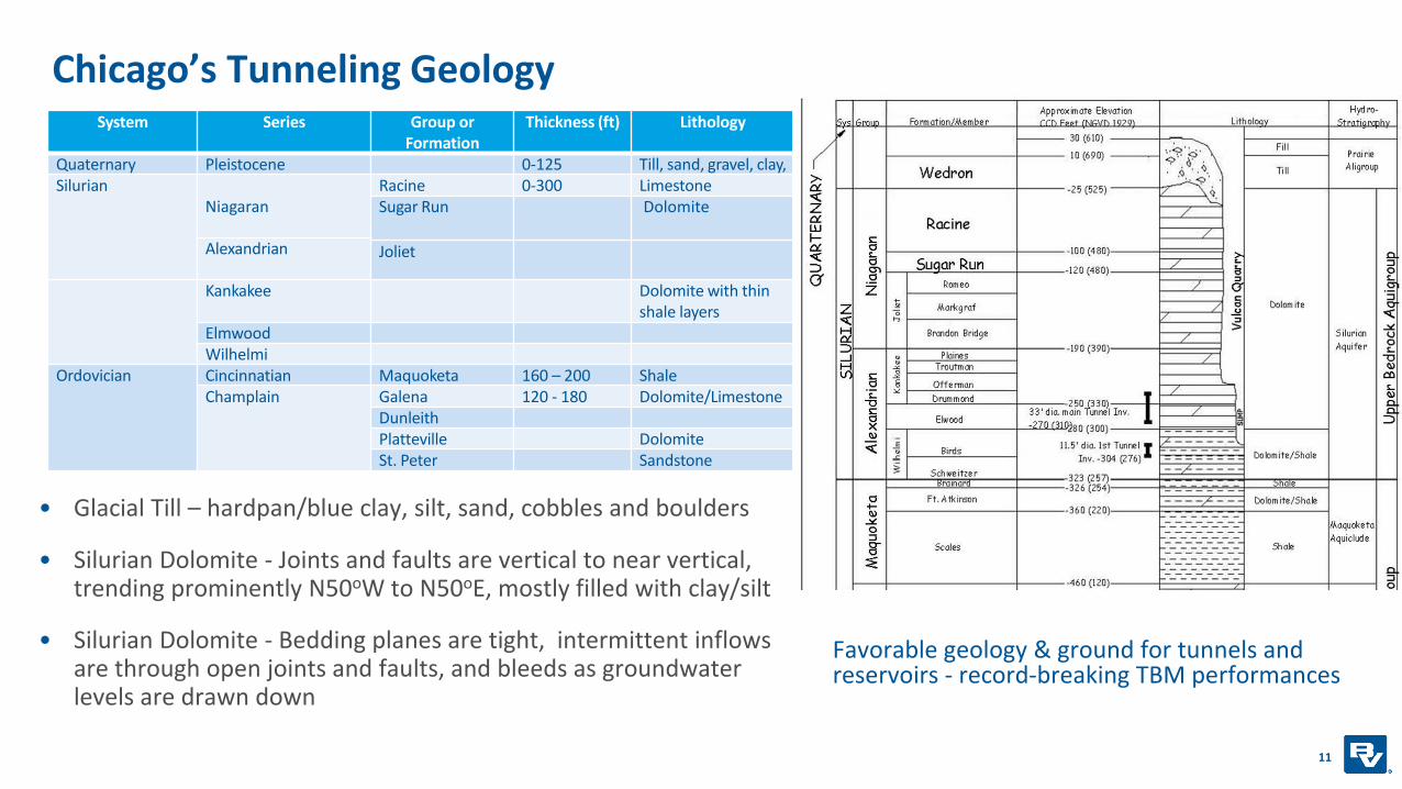
Chicago’s Tunneling Geology
• Glacial Till – hardpan/blue clay, silt, sand, cobbles and boulders
• Silurian Dolomite - Joints and faults are vertical to near vertical, trending prominently N50oW to N50oE, mostly filled with clay/silt
• Silurian Dolomite - Bedding planes are tight, intermittent inflows are through open joints and faults, and bleeds as groundwater levels are drawn down
11
System Series Group or Formation
Thickness (ft) Lithology
Quaternary Pleistocene 0-125 Till, sand, gravel, clay, Silurian
NiagaranRacine 0-300 LimestoneSugar Run Dolomite
Alexandrian Joliet
Kankakee Dolomite with thin shale layers
ElmwoodWilhelmi
Ordovician Cincinnatian Maquoketa 160 – 200 ShaleChamplain Galena 120 - 180 Dolomite/Limestone
DunleithPlatteville DolomiteSt. Peter Sandstone
Favorable geology & ground for tunnels and reservoirs - record-breaking TBM performances

Existing Tunnels and Deep Quarries Provide Excellent Data Source for Rock Tunnels
• Abundance of existing data
• Historic reversal of rivers and construction of the Illinois-Michigan Canal
• Deep surface quarries and underground aggregate mines
• Previous tunnels
• Foundations for tall buildings, bridges, and roadways
• Predictable Ground Conditions
• Geotechnical drilling and testing needs are far less than other locations due to already existing data, uniformity of ground, and past tunneling experience
• GBRs are kind of “optional” as there is an overwhelming tunneling experience available to tunnel constructors
• Groundwater – mostly dealt by dewatering (panning and pumping) and lowered water table in rock
12

Tunneling Aspects Unique to Chicago Area
13

Design Completion4 to 8 months6 to 8 months3 to 6 Mos.Design Start
Hydraulics
Operations & Maintenance
Compliance
Easements/Permits
Geotechnical
Environmental
Traffic/Community
Tunnels & Shafts
Pump Stations
Gates & Valves
Diversion Works
Cost Estimates
Preliminary Schedule
Procurement
TUNNEL DESIGN PROCESS
ConfirmFacility Plans
Basis of DesignFinal DesignPlans-Specs GBR*/GDR
AdvertiseContract
Pre-design / VE Workshops
Design Validation Process
Plans & Specs Development
COST AND CONSTRUCTABILITY
RISK MANAGEMENT
Preliminary Engineering
Typical Tunnel Design Process

Tunnels Risk Management Process
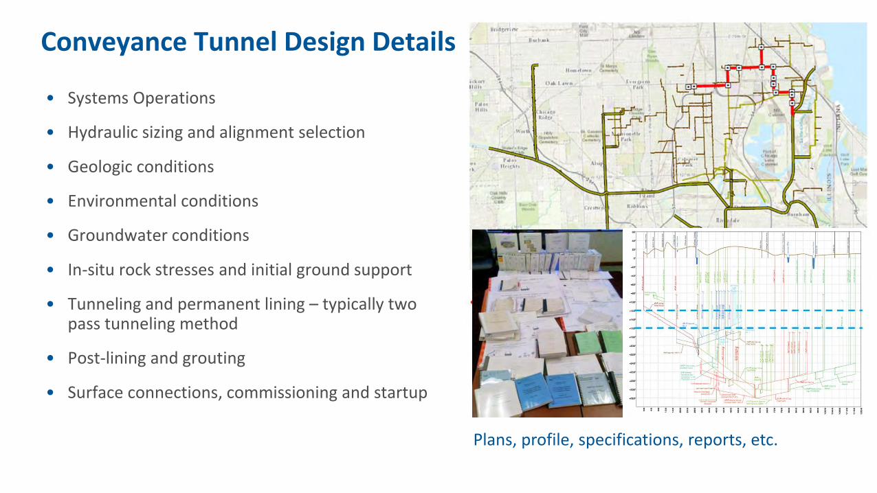
Conveyance Tunnel Design Details
• Systems Operations
• Hydraulic sizing and alignment selection
• Geologic conditions
• Environmental conditions
• Groundwater conditions
• In-situ rock stresses and initial ground support
• Tunneling and permanent lining – typically two pass tunneling method
• Post-lining and grouting
• Surface connections, commissioning and startup
Plans, profile, specifications, reports, etc.

Tunnel Sizing and Alignment Selection
• System Hydraulics & Operational Flexibility
• Horizontal/Vertical Alignment Evaluation:
• Risks (technical, political, and contractual)
• Shaft locations
• Easements
• Capital and operating costs
• Geotechnical considerations
• Community impacts
• Proximity to sensitive structures
• Tunneling under rivers, wetlands, etc.
• Permits
• Constructability issues
Tunnel alignment and shaft location selections can benefit from innovative tools and solutions in a virtual reality environment.

Tunnel Cost Analysis
Benchmarking to Recent Chicago Tunnels:
• Des Plaines Inflow ~ $125M (bid)
• Albany Park ~ $62M (bid)
• McCook Main Tunnel ~ $132M (bid)
• Cost of diversion works, gates, pump stations, etc. can be substantial and skew per foot/diaestimates.

Diversion Works and Drop Shafts Designs
Vortex Drop Shaft (Milwaukee)Plunge Drop Shaft (Chicago)

CSO to Tunnel
River
CSO Outfall
Storage Tunnel
Drop Shafts
Consolidation Sewer
Regulators
Wet
Weather
Deep Tunnel Pump Station to WWTP
Working Shaft
Combined SewerTo WWTP
WWTP
CSO to Tunnel
Combined Flow
to WWTP and
Tunnel
BEDROCK
SOILS
Understanding of How Deep Tunnel Systems WorkCombined Sewers Overflow (CSO) Management Tunnels

Chicago TARP – Tunnel and Reservoir Plan
• Largest combined sewer overflow and flood management system
• Services Chicago downtown and 123 suburban communities
• 110 miles of rock tunnels, 8 to 33-ft dia., 170 to 300-ft deep
• 3 mega reservoirs – two excavated in rock
Chicago’s largest infrastructure undertaking for nearly four decades
21
McCook Reservoir
Thornton Reservoir

Chicago Tunnel and Reservoir Plan - TARP
Operation Cycle
1. Dry Weather
2. Wet Weather
3. Interceptors and Tunnels Full
4. Reservoir Full
5. Store, Pump out, Treat, and Discharge

How did MWRD build TARP ?
• Storage and gravity conveyance system
• Tunnel Boring Machines (TBM)
• Excavated 150 to 300 ft below ground, through limestone rock
• Lined with concrete
• Unique inlet/drop shaft layout
• Self cleaning systems
Mainstream Tunnel system was the largest (30-ft dia.) and the longest (40.5 miles) TBM tunnel in the U.S.
when completed in 1985.

Little Calumet Tunnel - TBM & Cutter Head
Open-face, hard-rock gripper TBMs
Silurian dolomite (~ 15 to 25 kpsi)
Record-breaking advance rates and continuous tunnel drives
Minimal groundwater or gas problems
Hard rock TBM assembly
(for illustration, typically done in underground)
Chicago Area Hard Rock Tunneling Experience Runs Deep

Drop shafts, diversions, pumping stations
• Plunge Drop or Chicago style drop shafts
• 250 + across TARP
• Up to 300 ft deep and
4 to 17-ft dia.
• 600 plus diversion structures
• 3 pumping stations
• 550 miles of interceptor sewers

26
McCook Reservoir

McCook Reservoir and Tunnel Systems
Distribution Tunnels &
Chamber
Main Tunnel &
Gates
Courtesy of USACE

Flow from Chicagoland
Outlet to Reservoir
Outlet to Stickney
Air Vent
Isometric Schematic No Scale
TARP Mainstream Tunnel (in service)
To McCook Reservoir
Main Gates
McCook Reservoir - Main Tunnel SystemFrom Mainstream Tunnel (Chicago)
To Mainstream Pump Station & Stickney Treatment Plant
Flow in both directions

McCook Main Tunnel System Layout
29
To MS Pump Station & Stickney WRP
McCook Reservoir
From Mainstream TARP
Gates
Concrete Bulkhead
ConnectionGate / Construction Access ShaftPortal / Energy
Dissipation
Reservoir Region
Bifurcation & Transition Region
TAPR / Mainstream TunnelConnection Region
Concrete Bulkhead

McCook Main Tunnel System – Plan & Profile

Main Tunnel System - Gate Chamber Layout

Numerical Modeling Using UDEC (Universal Distinct Element Code)• Applicable for tunnels and shafts with circular
and horseshoe shape geometries
• Incorporates existing tunnel lining and support details
• Two dimensional numerical program based on the distinct element method for discontinuummodeling. UDEC simulates the response of soils and discontinuous rock mass subjected to either static or dynamic loading
• Influence of water pressure
• Cohesion and friction of intact soil/rock and discontinuities.
• Shear strength of planar and rough surfaces, filled joints, faults, etc.
Successfully performed for the Chicago area tunnels. 32

Unique Features - Connection to Existing TARP Mainstream Tunnel
• Optimized for hydraulics to manage large flows (30,000 cfs) and velocities (up to 35 fps)
• Live connection while TARP tunnel is kept in service
• 16.5 ft radius sides allows smooth transition to cross-section of 33 ft diameter Mainstream Tunnel
• Flat top maximizes the height of the profile across the connection section and flow from Mainstream Tunnel is forced downwards
• Reducing the height, but increasing the width results in a flare for a smoother turning of the flow into the Main Tunnel and Reservoir
33
Horizontal sweep radius = 7.5ft
Horizontal sweep radius = 30ft
Horizontal sweep radius = 5ft
33.6ft 34.5ft 35.8ft 37.6ft
31.375ft
29.75ft
28.125ft
26.5ft
33ft
Section A-A Section B-B Section C-C Section D-D Section E-E
Section F-F
Joint smoothed to 1.5ft radius
Sides = 16.5ft radius
Corners = 4ft radius
General Detail for Sections B-B to E-E
A
A
B
B
E
E
C
C
D
D
Elevation
Plan
F
F24ft 24ft12ft 12ft

Mainstream Tunnel Connection - Elliptical Mitre
Velocity on central plane
Region with sub-atmospheric pressure
Maximum velocity = 48 fpsMinimum absolute pressure = 0.6atm
Note separation of flow at connection

High Head Wheel Gates for Tunnels
35
Large gates allow for hydraulic controls in tunnels, systems operations and storage optimization, and maintenance of reservoirs and tunnels
Factory Acceptance Tests for gates for McCook

McCook Main Gates Design - Computational Fluid Dynamics (CFD) Modeling
• High head wheel gates for tunnels are unique to Chicago (three gate systems installed, fourth is under construction)
• McCook Gates - total of six (6) 29-ft high x 14.5-ft wide wheel gates inside 88-ft diashaft and bifurcated tunnel
• Operates under up to 300 psi pressure
• Separate design, fabrication, and installation contracts
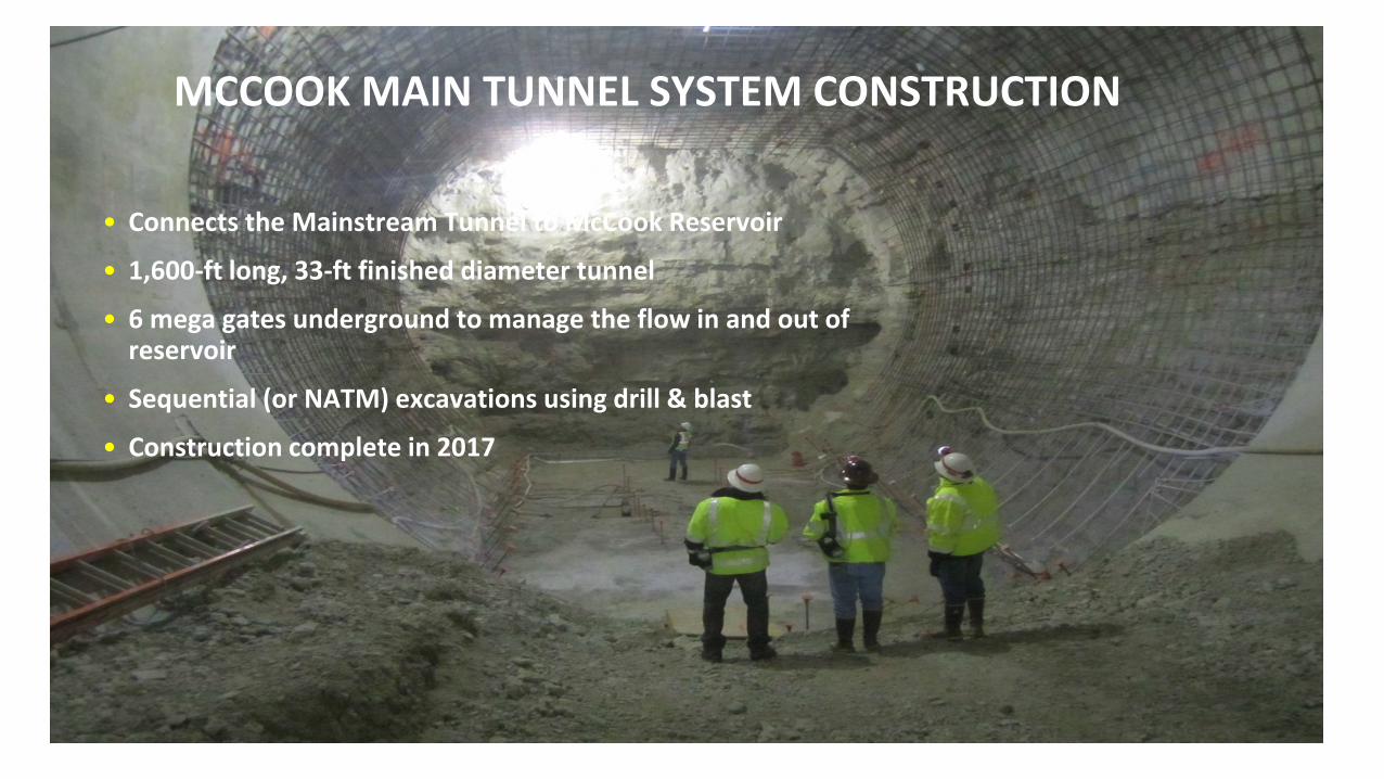
MCCOOK MAIN TUNNEL SYSTEM CONSTRUCTION
• Connects the Mainstream Tunnel to McCook Reservoir
• 1,600-ft long, 33-ft finished diameter tunnel
• 6 mega gates underground to manage the flow in and out of reservoir
• Sequential (or NATM) excavations using drill & blast
• Construction complete in 2017

DROP Structures – BIM & 3D CONSTRUCTION RENDERINGs

39Construction Shaft and Site Layout

40Gate Chamber and tunnel heading excavation

41Excavated tunnel and reinforcement (concrete forms in the background)

42Concrete form work

Bifurcation Steel Liner
43

DRILL & BLAST PLAN
• Sequential (or NATM) excavation included top heading (upper half of tunnel) removal followed with lower bench excavation
• One unique drill & blast excavation layout included a single round full 36-dia face and 15-feet long section prior to connection to Mainstream Tunnel
44

45
Lined sections of the tunnel and gates bifurcation area

Bifurcation Steel Liner
• 3.5 million lbs of fabricated steel
• 32 Fabricated Sections
• Welding
• Shop Welds
• 5,300lf Full Penetration Weld
• 22,000lf fillet welds
• Field Welds
• 5,000lf Full Penetration Weld
• Shipments
• By Fabricator – 48 Permit loads (Missoula to Chicago)
• Average shipment size 16ft Wide x 35ft Long x 13.5ft Tall

47
Steel liner installation around gate openings with tolerance less than ½-inch over 60-ft height

48Gate chamber concrete placement

Mainstream Connection - Top Heading and Construction Platform in TARP tunnel

Mainstream Connection – Upstream Cofferdam in Tunnel and Lining Work

Mainstream Connection – Completed.
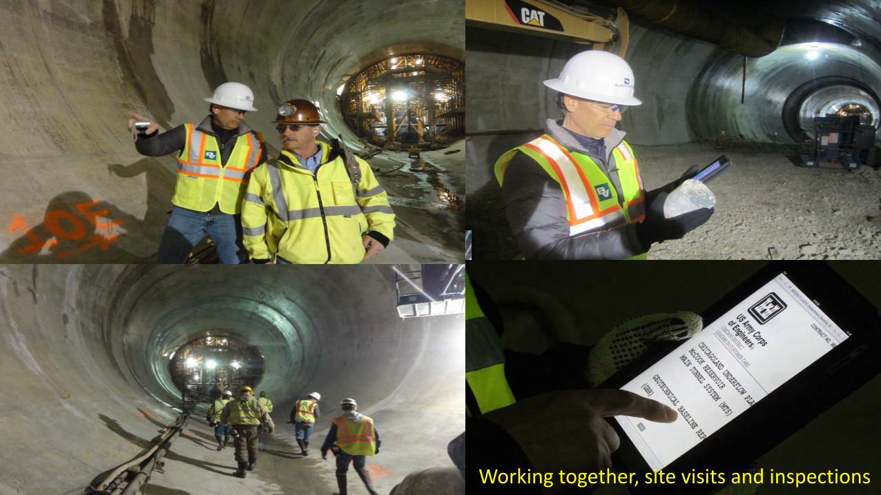
52Working together, site visits and inspections

Partnering
• Bi-monthly partnering meetings facilitated by Kiewit
• Discussion of outstanding issues, resolutions, and action items
• Participants include USACE, MWRD, Kiewit and Black & Veatch
• Followed by site visits as needed.

Thornton Reservoir Creek Tunnel • Tunnel structural integrity modeling – predictive
approach
• Geology and geotechnical (existing borings, tunnel construction data)
• Supplemental soil borings, wells, piezometers, falling head and pump tests, and dye testing to characterize ground conditions and permeability of soils/rock
• Evaluate any signs of movements/ground losses in vicinity of shafts and tunnels
• Instrumentation and monitoring plan during dewatering
• Emergency Response Plan
54
MWRD’s Thorn Creek Tunnel – Example of an unlined rock tunnel. B&V designed and implemented concrete lining and contact grouting program for this 3,800 feet long tunnel rehab.

Thornton Composite Reservoir
• Serves TARP Calumet System and also designed
to capture Thorn Creek over-the-bank flood
waters when Transitional Reservoir is
decommissioned
• Key components - groundwater protection
system, connecting tunnels and gates to TARP
system and a roller-compacted concrete (RCC)
dam
• Dewaters to Calumet Pump Station and Water
Reclamation Plant
Thornton Composite Reservoir received the 2016 Project of the Year Recognition and Award by the American Public Works Association (APWA)

Thornton Composite Reservoir and Thorn Creek Diversion Tunnel in foreground, TARP tunnels, drop shafts & Calumet WRP in background

Thornton Composite Reservoir
• 7.8 BG Reservoir (24,100 acre-feet)
• Allocation: 4.8 BG CSOs and 3.0 BG Thorn Creek storm water
(courtesy MWRDGC)

Thornton Composite Reservoir
• Completion of aggregate mining
• Perimeter Grout Curtain
• Roller-Compacted-Concrete (RCC)
Dam
• TARP Indiana Avenue Tunnel
Connection and Main Gates
• Thorn Creek Tunnel Connection
and Reservoir Preparations

North Lobe
Existing Mainstream Tunnel
Existing Dewatering Tunnel
Existing Diversion Tunnel
Gates
Connecting Tunnel
Grout Curtain
Drainage Adit
Tunnel PlugTunnel Plug
Thorn Creek Tunnel
Visitor Parking & Working Pad
Quarry Plugs
Tollway Grout Curtain
Tollway Dam

Thorn Creek Diversion Tunnel Connection to Thornton Composite Reservoir

Thorn Creek Connection Tunnel
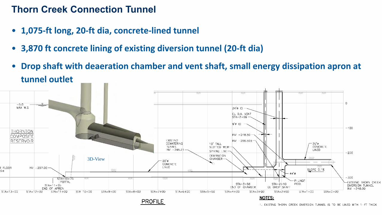
• 1,075-ft long, 20-ft dia, concrete-lined tunnel
• 3,870 ft concrete lining of existing diversion tunnel (20-ft dia)
• Drop shaft with deaeration chamber and vent shaft, small energy dissipation apron at
tunnel outlet
Thorn Creek Connection Tunnel
3D-View

Perimeter Grout Curtain
• Inclined - double row
• Primary, Secondary, and
Tertiary boreholes
• Maximum depth of 500 ft
• Balanced-stabilized grout
mixes
• Automated grout control
systems

Grout Curtain Installation
Comparison of Water Pressure Testing vs. Pressure Grouting
Pressure GroutingDownhole Geophysics
Grout Takes
Water Takes

Drainage Adit Conversion
• Reinforced concrete tunnel plugs at both ends
• Drain holes to increase effectiveness
• Drilled upward at 30-ft intervals along aditcrown
• Inclined 30o from vertical to better intercept joints
• 10-ft dia access shaft and connection tunnel
• To access drainage adit
• Potential back-up for dewatering adit

January 13, 2010B&V -
Drainage Adit Conversion
Reduce seepage from Reservoir passing to Main Lobe and minimize potential instability of Tollway Dam

Thornton Reservoir and Tunnels – APWA 2016 Project of the Year Award

Chicago River Front - many fish species have returned, now a regular place for the Annual Bass Fishing Tournament !
Acknowledgements
U.S. Army Corps of Engineers
CHICAGO DISTRICT
F.H. Paschen
