mcguire nuclear station ufsar appendix 8a. tables
TRANSCRIPT
McGuire Nuclear Station UFSAR Appendix 8A. Tables
Appendix 8A. Tables
McGuire Nuclear Station UFSAR Table 8-1 (Page 1 of 12)
(13 OCT 2018)
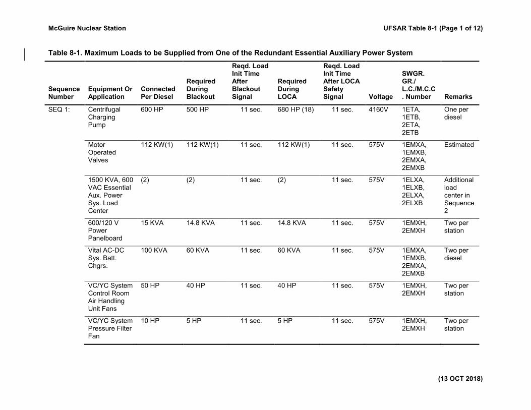
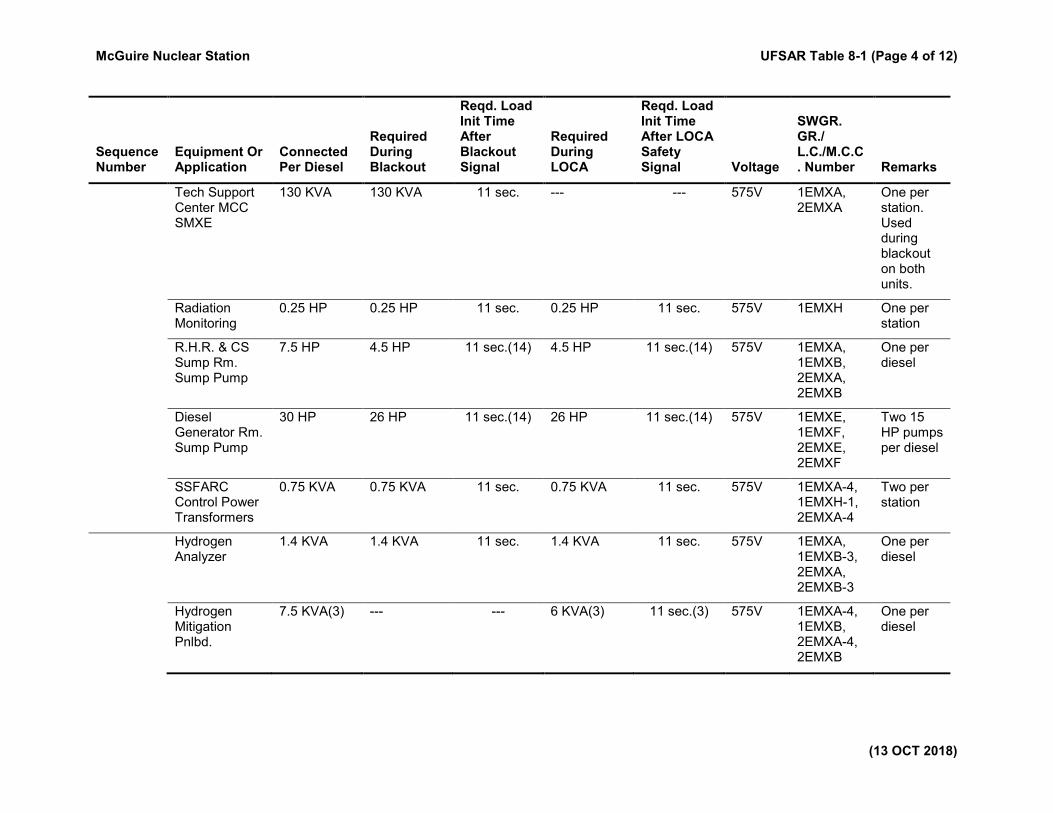
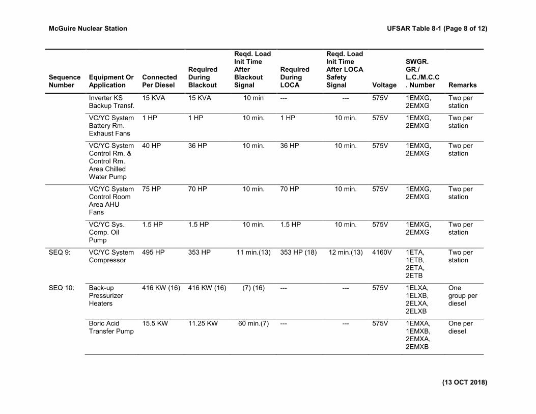
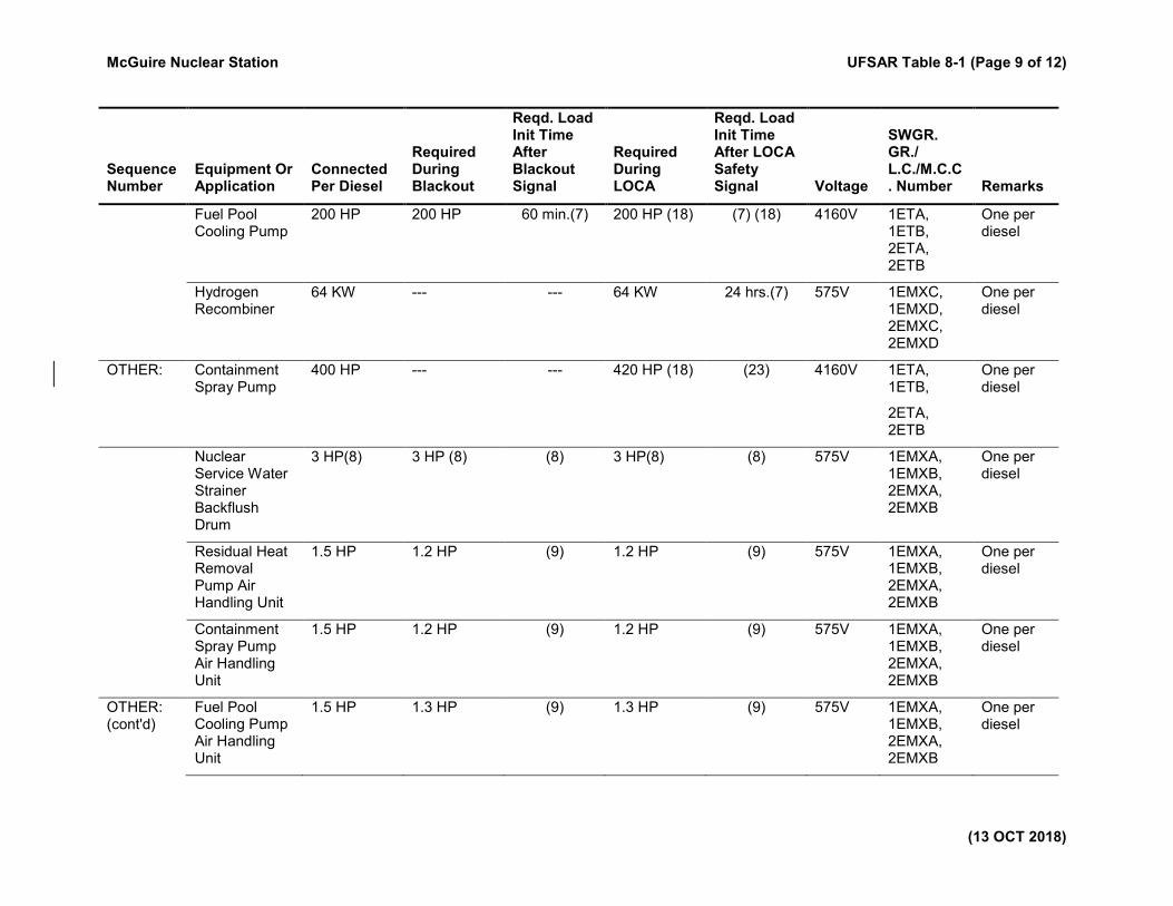
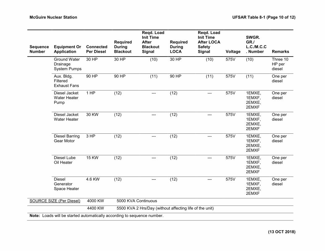
Table 8-1. Maximum Loads to be Supplied from One of the Redundant Essential Auxiliary Power System
Sequence Number
Equipment Or Application
Connected Per Diesel
Required During Blackout
Reqd. Load Init Time After Blackout Signal
Required During LOCA
Reqd. Load Init Time After LOCA Safety Signal Voltage
SWGR. GR./ L.C./M.C.C. Number Remarks
SEQ 1: Centrifugal Charging Pump
600 HP 500 HP 11 sec. 680 HP (18) 11 sec. 4160V 1ETA, 1ETB, 2ETA, 2ETB
One per diesel
Motor Operated Valves
112 KW(1) 112 KW(1) 11 sec. 112 KW(1) 11 sec. 575V 1EMXA, 1EMXB, 2EMXA, 2EMXB
Estimated
1500 KVA, 600 VAC Essential Aux. Power Sys. Load Center
(2) (2) 11 sec. (2) 11 sec. 575V 1ELXA, 1ELXB, 2ELXA, 2ELXB
Additional load center in Sequence 2
600/120 V Power Panelboard
15 KVA 14.8 KVA 11 sec. 14.8 KVA 11 sec. 575V 1EMXH, 2EMXH
Two per station
Vital AC-DC Sys. Batt. Chgrs.
100 KVA 60 KVA 11 sec. 60 KVA 11 sec. 575V 1EMXA, 1EMXB, 2EMXA, 2EMXB
Two per diesel
VC/YC System Control Room Air Handling Unit Fans
50 HP 40 HP 11 sec. 40 HP 11 sec. 575V 1EMXH, 2EMXH
Two per station
VC/YC System Pressure Filter Fan
10 HP 5 HP 11 sec. 5 HP 11 sec. 575V 1EMXH, 2EMXH
Two per station
McGuire Nuclear Station UFSAR Table 8-1 (Page 2 of 12)
(13 OCT 2018)
Sequence Number
Equipment Or Application
Connected Per Diesel
Required During Blackout
Reqd. Load Init Time After Blackout Signal
Required During LOCA
Reqd. Load Init Time After LOCA Safety Signal Voltage
SWGR. GR./ L.C./M.C.C. Number Remarks
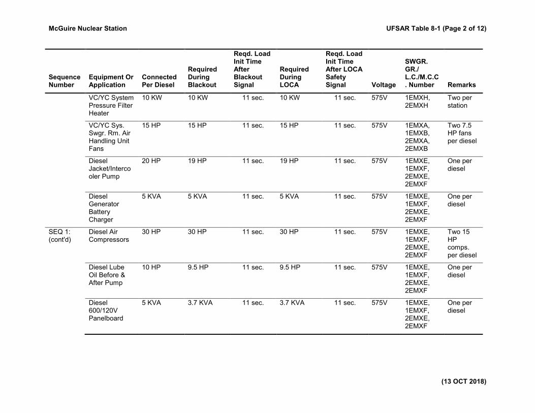
VC/YC System Pressure Filter Heater
10 KW 10 KW 11 sec. 10 KW 11 sec. 575V 1EMXH, 2EMXH
Two per station
VC/YC Sys. Swgr. Rm. Air Handling Unit Fans
15 HP 15 HP 11 sec. 15 HP 11 sec. 575V 1EMXA, 1EMXB, 2EMXA, 2EMXB
Two 7.5 HP fans per diesel
Diesel Jacket/Intercooler Pump
20 HP 19 HP 11 sec. 19 HP 11 sec. 575V 1EMXE, 1EMXF, 2EMXE, 2EMXF
One per diesel
Diesel Generator Battery Charger
5 KVA 5 KVA 11 sec. 5 KVA 11 sec. 575V 1EMXE, 1EMXF, 2EMXE, 2EMXF
One per diesel
SEQ 1: (cont'd)
Diesel Air Compressors
30 HP 30 HP 11 sec. 30 HP 11 sec. 575V 1EMXE, 1EMXF, 2EMXE, 2EMXF
Two 15 HP comps. per diesel
Diesel Lube Oil Before & After Pump
10 HP 9.5 HP 11 sec. 9.5 HP 11 sec. 575V 1EMXE, 1EMXF, 2EMXE, 2EMXF
One per diesel
Diesel 600/120V Panelboard
5 KVA 3.7 KVA 11 sec. 3.7 KVA 11 sec. 575V 1EMXE, 1EMXF, 2EMXE, 2EMXF
One per diesel
McGuire Nuclear Station UFSAR Table 8-1 (Page 3 of 12)
(13 OCT 2018)
Sequence Number
Equipment Or Application
Connected Per Diesel
Required During Blackout
Reqd. Load Init Time After Blackout Signal
Required During LOCA
Reqd. Load Init Time After LOCA Safety Signal Voltage
SWGR. GR./ L.C./M.C.C. Number Remarks
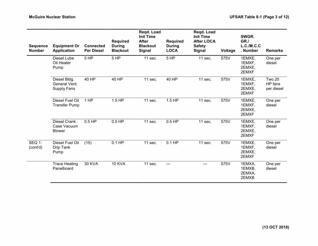
Diesel Lube Oil Heater Pump
5 HP 5 HP 11 sec. 5 HP 11 sec. 575V 1EMXE, 1EMXF, 2EMXE, 2EMXF
One per diesel
Diesel Bldg. General Vent. Supply Fans
40 HP 40 HP 11 sec. 40 HP 11 sec. 575V 1EMXE, 1EMXF, 2EMXE, 2EMXF
Two 20 HP fans per diesel
Diesel Fuel Oil Transfer Pump
1 HP 1.5 HP 11 sec. 1.5 HP 11 sec. 575V 1EMXE, 1EMXF, 2EMXE, 2EMXF
One per diesel
Diesel Crank Case Vacuum Blower
0.5 HP 0.5 HP 11 sec. 0.5 HP 11 sec. 575V 1EMXE, 1EMXF, 2EMXE, 2EMXF
One per diesel
SEQ 1: (cont'd)
Diesel Fuel Oil Drip Tank Pump
(15) 0.1 HP 11 sec. 0.1 HP 11 sec. 575V 1EMXE, 1EMXF, 2EMXE, 2EMXF
One per diesel
Trace Heating Panelboard
30 KVA 10 KVA 11 sec. --- --- 575V 1EMXA, 1EMXB, 2EMXA, 2EMXB
One per diesel
McGuire Nuclear Station UFSAR Table 8-1 (Page 4 of 12)
(13 OCT 2018)
Sequence Number
Equipment Or Application
Connected Per Diesel
Required During Blackout
Reqd. Load Init Time After Blackout Signal
Required During LOCA
Reqd. Load Init Time After LOCA Safety Signal Voltage
SWGR. GR./ L.C./M.C.C. Number Remarks
Tech Support Center MCC SMXE
130 KVA 130 KVA 11 sec. --- --- 575V 1EMXA, 2EMXA
One per station. Used during blackout on both units.
Radiation Monitoring
0.25 HP 0.25 HP 11 sec. 0.25 HP 11 sec. 575V 1EMXH One per station
R.H.R. & CS Sump Rm. Sump Pump
7.5 HP 4.5 HP 11 sec.(14) 4.5 HP 11 sec.(14) 575V 1EMXA, 1EMXB, 2EMXA, 2EMXB
One per diesel
Diesel Generator Rm. Sump Pump
30 HP 26 HP 11 sec.(14) 26 HP 11 sec.(14) 575V 1EMXE, 1EMXF, 2EMXE, 2EMXF
Two 15 HP pumps per diesel
SSFARC Control Power Transformers
0.75 KVA 0.75 KVA 11 sec. 0.75 KVA 11 sec. 575V 1EMXA-4, 1EMXH-1, 2EMXA-4
Two per station
Hydrogen Analyzer
1.4 KVA 1.4 KVA 11 sec. 1.4 KVA 11 sec. 575V 1EMXA, 1EMXB-3, 2EMXA, 2EMXB-3
One per diesel
Hydrogen Mitigation Pnlbd.
7.5 KVA(3) --- --- 6 KVA(3) 11 sec.(3) 575V 1EMXA-4, 1EMXB, 2EMXA-4, 2EMXB
One per diesel
McGuire Nuclear Station UFSAR Table 8-1 (Page 5 of 12)
(13 OCT 2018)
Sequence Number
Equipment Or Application
Connected Per Diesel
Required During Blackout
Reqd. Load Init Time After Blackout Signal
Required During LOCA
Reqd. Load Init Time After LOCA Safety Signal Voltage
SWGR. GR./ L.C./M.C.C. Number Remarks
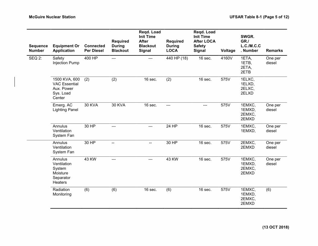
SEQ 2: Safety Injection Pump
400 HP --- --- 440 HP (18) 16 sec. 4160V 1ETA, 1ETB, 2ETA, 2ETB
One per diesel
1500 KVA, 600 VAC Essential Aux. Power Sys. Load Center
(2) (2) 16 sec. (2) 16 sec. 575V 1ELXC, 1ELXD, 2ELXC, 2ELXD
Emerg. AC Lighting Panel
30 KVA 30 KVA 16 sec. --- --- 575V 1EMXC, 1EMXD, 2EMXC, 2EMXD
One per diesel
Annulus Ventilation System Fan
30 HP --- --- 24 HP 16 sec. 575V 1EMXC, 1EMXD,
One per diesel
Annulus Ventilation System Fan
30 HP -- -- 30 HP 16 sec. 575V 2EMXC, 2EMXD
One per diesel
Annulus Ventilation System Moisture Separator Heaters
43 KW --- --- 43 KW 16 sec. 575V 1EMXC, 1EMXD, 2EMXC, 2EMXD
One per diesel
Radiation Monitoring
(6) (6) 16 sec. (6) 16 sec. 575V 1EMXC, 1EMXD, 2EMXC, 2EMXD
(6)
McGuire Nuclear Station UFSAR Table 8-1 (Page 6 of 12)
(13 OCT 2018)
Sequence Number
Equipment Or Application
Connected Per Diesel
Required During Blackout
Reqd. Load Init Time After Blackout Signal
Required During LOCA
Reqd. Load Init Time After LOCA Safety Signal Voltage
SWGR. GR./ L.C./M.C.C. Number Remarks
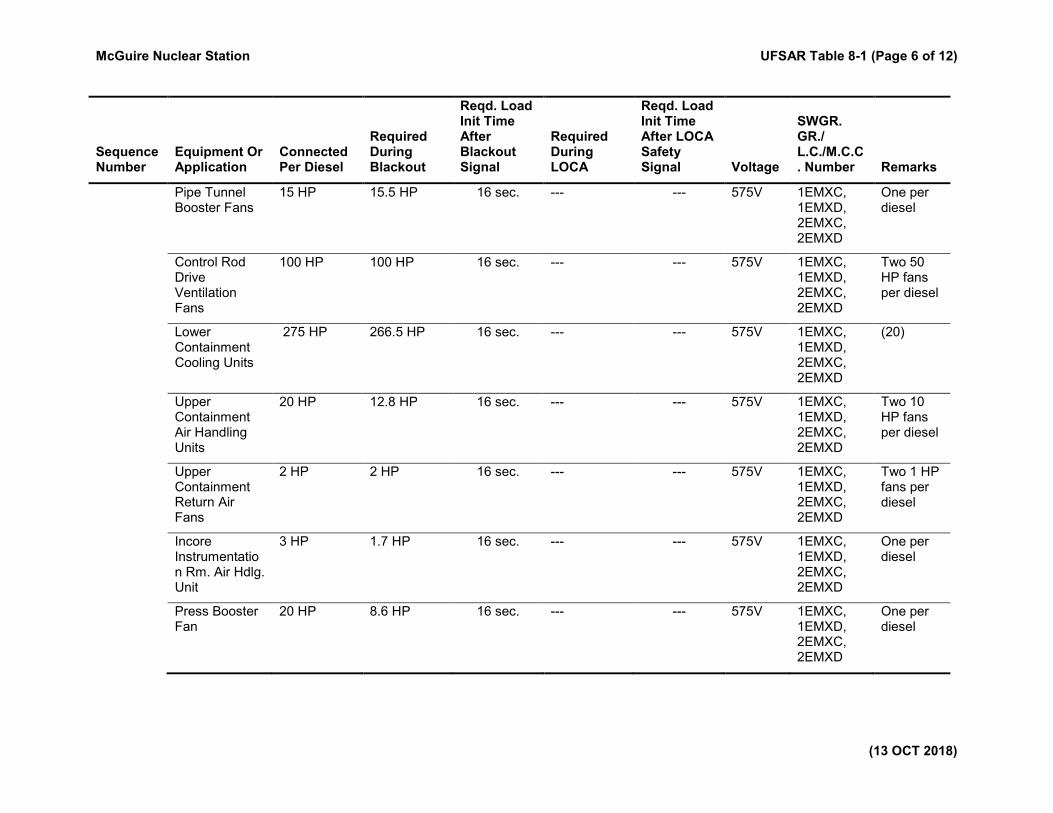
Pipe Tunnel Booster Fans
15 HP 15.5 HP 16 sec. --- --- 575V 1EMXC, 1EMXD, 2EMXC, 2EMXD
One per diesel
Control Rod Drive Ventilation Fans
100 HP 100 HP 16 sec. --- --- 575V 1EMXC, 1EMXD, 2EMXC, 2EMXD
Two 50 HP fans per diesel
Lower Containment Cooling Units
275 HP 266.5 HP 16 sec. --- --- 575V 1EMXC, 1EMXD, 2EMXC, 2EMXD
(20)
Upper Containment Air Handling Units
20 HP 12.8 HP 16 sec. --- --- 575V 1EMXC, 1EMXD, 2EMXC, 2EMXD
Two 10 HP fans per diesel
Upper Containment Return Air Fans
2 HP 2 HP 16 sec. --- --- 575V 1EMXC, 1EMXD, 2EMXC, 2EMXD
Two 1 HP fans per diesel
Incore Instrumentation Rm. Air Hdlg. Unit
3 HP 1.7 HP 16 sec. --- --- 575V 1EMXC, 1EMXD, 2EMXC, 2EMXD
One per diesel
Press Booster Fan
20 HP 8.6 HP 16 sec. --- --- 575V 1EMXC, 1EMXD, 2EMXC, 2EMXD
One per diesel
McGuire Nuclear Station UFSAR Table 8-1 (Page 7 of 12)
(13 OCT 2018)
Sequence Number
Equipment Or Application
Connected Per Diesel
Required During Blackout
Reqd. Load Init Time After Blackout Signal
Required During LOCA
Reqd. Load Init Time After LOCA Safety Signal Voltage
SWGR. GR./ L.C./M.C.C. Number Remarks
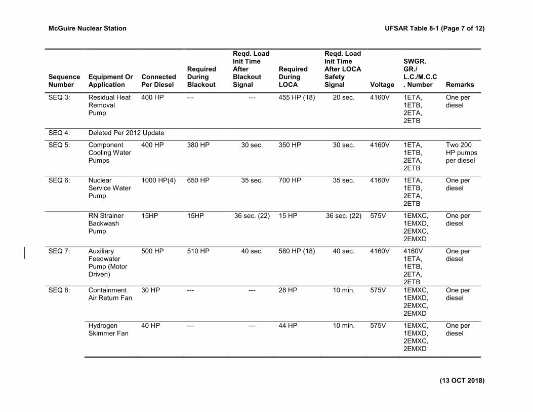
SEQ 3: Residual Heat Removal Pump
400 HP --- --- 455 HP (18) 20 sec. 4160V 1ETA, 1ETB, 2ETA, 2ETB
One per diesel
SEQ 4: Deleted Per 2012 Update
SEQ 5: Component Cooling Water Pumps
400 HP 380 HP 30 sec. 350 HP 30 sec. 4160V 1ETA, 1ETB, 2ETA, 2ETB
Two 200 HP pumps per diesel
SEQ 6: Nuclear Service Water Pump
1000 HP(4) 650 HP 35 sec. 700 HP 35 sec. 4160V 1ETA, 1ETB, 2ETA, 2ETB
One per diesel
RN Strainer Backwash Pump
15HP 15HP 36 sec. (22) 15 HP 36 sec. (22) 575V 1EMXC, 1EMXD, 2EMXC, 2EMXD
One per diesel
SEQ 7: Auxiliary Feedwater Pump (Motor Driven)
500 HP 510 HP 40 sec. 580 HP (18) 40 sec. 4160V 4160V 1ETA, 1ETB, 2ETA, 2ETB
One per diesel
SEQ 8: Containment Air Return Fan
30 HP --- --- 28 HP 10 min. 575V 1EMXC, 1EMXD, 2EMXC, 2EMXD
One per diesel
Hydrogen Skimmer Fan
40 HP --- --- 44 HP 10 min. 575V 1EMXC, 1EMXD, 2EMXC, 2EMXD
One per diesel
McGuire Nuclear Station UFSAR Table 8-1 (Page 8 of 12)
(13 OCT 2018)
Sequence Number
Equipment Or Application
Connected Per Diesel
Required During Blackout
Reqd. Load Init Time After Blackout Signal
Required During LOCA
Reqd. Load Init Time After LOCA Safety Signal Voltage
SWGR. GR./ L.C./M.C.C. Number Remarks
Inverter KS Backup Transf.
15 KVA 15 KVA 10 min --- --- 575V 1EMXG, 2EMXG
Two per station
VC/YC System Battery Rm. Exhaust Fans
1 HP 1 HP 10 min. 1 HP 10 min. 575V 1EMXG, 2EMXG
Two per station
VC/YC System Control Rm. & Control Rm. Area Chilled Water Pump
40 HP 36 HP 10 min. 36 HP 10 min. 575V 1EMXG, 2EMXG
Two per station
VC/YC System Control Room Area AHU Fans
75 HP 70 HP 10 min. 70 HP 10 min. 575V 1EMXG, 2EMXG
Two per station
VC/YC Sys. Comp. Oil Pump
1.5 HP 1.5 HP 10 min. 1.5 HP 10 min. 575V 1EMXG, 2EMXG
Two per station
SEQ 9: VC/YC System Compressor
495 HP 353 HP 11 min.(13) 353 HP (18) 12 min.(13) 4160V 1ETA, 1ETB, 2ETA, 2ETB
Two per station
SEQ 10: Back-up Pressurizer Heaters
416 KW (16) 416 KW (16) (7) (16) --- --- 575V 1ELXA, 1ELXB, 2ELXA, 2ELXB
One group per diesel
Boric Acid Transfer Pump
15.5 KW 11.25 KW 60 min.(7) --- --- 575V 1EMXA, 1EMXB, 2EMXA, 2EMXB
One per diesel
McGuire Nuclear Station UFSAR Table 8-1 (Page 9 of 12)
(13 OCT 2018)
Sequence Number
Equipment Or Application
Connected Per Diesel
Required During Blackout
Reqd. Load Init Time After Blackout Signal
Required During LOCA
Reqd. Load Init Time After LOCA Safety Signal Voltage
SWGR. GR./ L.C./M.C.C. Number Remarks
Fuel Pool Cooling Pump
200 HP 200 HP 60 min.(7) 200 HP (18) (7) (18) 4160V 1ETA, 1ETB, 2ETA, 2ETB
One per diesel
Hydrogen Recombiner
64 KW --- --- 64 KW 24 hrs.(7) 575V 1EMXC, 1EMXD, 2EMXC, 2EMXD
One per diesel
OTHER: Containment Spray Pump
400 HP --- --- 420 HP (18) (23) 4160V 1ETA, 1ETB,
2ETA, 2ETB
One per diesel
Nuclear Service Water Strainer Backflush Drum
3 HP(8) 3 HP (8) (8) 3 HP(8) (8) 575V 1EMXA, 1EMXB, 2EMXA, 2EMXB
One per diesel
Residual Heat Removal Pump Air Handling Unit
1.5 HP 1.2 HP (9) 1.2 HP (9) 575V 1EMXA, 1EMXB, 2EMXA, 2EMXB
One per diesel
Containment Spray Pump Air Handling Unit
1.5 HP 1.2 HP (9) 1.2 HP (9) 575V 1EMXA, 1EMXB, 2EMXA, 2EMXB
One per diesel
OTHER: (cont'd)
Fuel Pool Cooling Pump Air Handling Unit
1.5 HP 1.3 HP (9) 1.3 HP (9) 575V 1EMXA, 1EMXB, 2EMXA, 2EMXB
One per diesel
McGuire Nuclear Station UFSAR Table 8-1 (Page 10 of 12)
(13 OCT 2018)
Sequence Number
Equipment Or Application
Connected Per Diesel
Required During Blackout
Reqd. Load Init Time After Blackout Signal
Required During LOCA
Reqd. Load Init Time After LOCA Safety Signal Voltage
SWGR. GR./ L.C./M.C.C. Number Remarks
Ground Water Drainage System Pumps
30 HP 30 HP (10) 30 HP (10) 575V (10) Three 10 HP per diesel
Aux. Bldg. Filtered Exhaust Fans
90 HP 90 HP (11) 90 HP (11) 575V (11) One per diesel
Diesel Jacket Water Heater Pump
1 HP (12) --- (12) --- 575V 1EMXE, 1EMXF, 2EMXE, 2EMXF
One per diesel
Diesel Jacket Water Heater
30 KW (12) --- (12) --- 575V 1EMXE, 1EMXF, 2EMXE, 2EMXF
One per diesel
Diesel Barring Gear Motor
3 HP (12) --- (12) --- 575V 1EMXE, 1EMXF, 2EMXE, 2EMXF
One per diesel
Diesel Lube Oil Heater
15 KW (12) --- (12) --- 575V 1EMXE, 1EMXF, 2EMXE, 2EMXF
One per diesel
Diesel Generator Space Heater
4.6 KW (12) --- (12) --- 575V 1EMXE, 1EMXF, 2EMXE, 2EMXF
One per diesel
SOURCE SIZE (Per Diesel) 4000 KW 5000 KVA Continuous
4400 KW 5500 KVA 2 Hrs/Day (without affecting life of the unit)
Note: Loads will be started automatically according to sequence number.
McGuire Nuclear Station UFSAR Table 8-1 (Page 11 of 12)
(13 OCT 2018)
Sequence Number
Equipment Or Application
Connected Per Diesel
Required During Blackout
Reqd. Load Init Time After Blackout Signal
Required During LOCA
Reqd. Load Init Time After LOCA Safety Signal Voltage
SWGR. GR./ L.C./M.C.C. Number Remarks
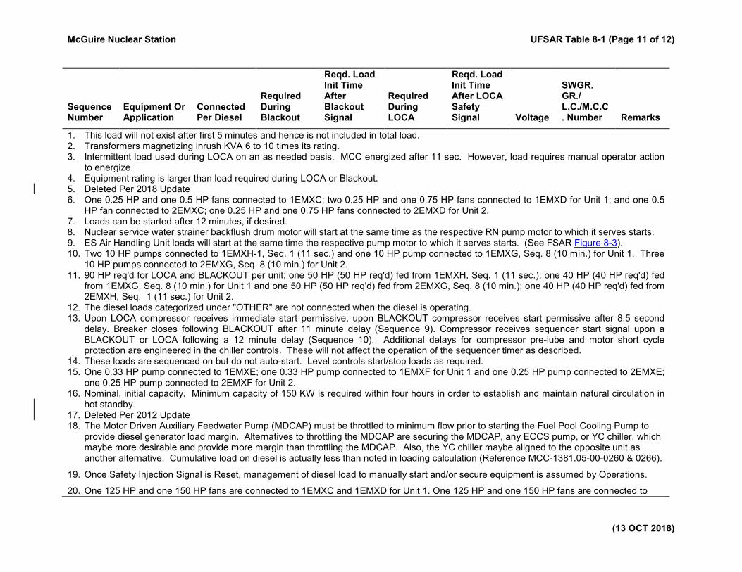
1. This load will not exist after first 5 minutes and hence is not included in total load. 2. Transformers magnetizing inrush KVA 6 to 10 times its rating. 3. Intermittent load used during LOCA on an as needed basis. MCC energized after 11 sec. However, load requires manual operator action
to energize. 4. Equipment rating is larger than load required during LOCA or Blackout. 5. Deleted Per 2018 Update 6. One 0.25 HP and one 0.5 HP fans connected to 1EMXC; two 0.25 HP and one 0.75 HP fans connected to 1EMXD for Unit 1; and one 0.5
HP fan connected to 2EMXC; one 0.25 HP and one 0.75 HP fans connected to 2EMXD for Unit 2. 7. Loads can be started after 12 minutes, if desired. 8. Nuclear service water strainer backflush drum motor will start at the same time as the respective RN pump motor to which it serves starts. 9. ES Air Handling Unit loads will start at the same time the respective pump motor to which it serves starts. (See FSAR Figure 8-3). 10. Two 10 HP pumps connected to 1EMXH-1, Seq. 1 (11 sec.) and one 10 HP pump connected to 1EMXG, Seq. 8 (10 min.) for Unit 1. Three
10 HP pumps connected to 2EMXG, Seq. 8 (10 min.) for Unit 2. 11. 90 HP req'd for LOCA and BLACKOUT per unit; one 50 HP (50 HP req'd) fed from 1EMXH, Seq. 1 (11 sec.); one 40 HP (40 HP req'd) fed
from 1EMXG, Seq. 8 (10 min.) for Unit 1 and one 50 HP (50 HP req'd) fed from 2EMXG, Seq. 8 (10 min.); one 40 HP (40 HP req'd) fed from 2EMXH, Seq. 1 (11 sec.) for Unit 2.
12. The diesel loads categorized under "OTHER" are not connected when the diesel is operating. 13. Upon LOCA compressor receives immediate start permissive, upon BLACKOUT compressor receives start permissive after 8.5 second
delay. Breaker closes following BLACKOUT after 11 minute delay (Sequence 9). Compressor receives sequencer start signal upon a BLACKOUT or LOCA following a 12 minute delay (Sequence 10). Additional delays for compressor pre-lube and motor short cycle protection are engineered in the chiller controls. These will not affect the operation of the sequencer timer as described.
14. These loads are sequenced on but do not auto-start. Level controls start/stop loads as required. 15. One 0.33 HP pump connected to 1EMXE; one 0.33 HP pump connected to 1EMXF for Unit 1 and one 0.25 HP pump connected to 2EMXE;
one 0.25 HP pump connected to 2EMXF for Unit 2. 16. Nominal, initial capacity. Minimum capacity of 150 KW is required within four hours in order to establish and maintain natural circulation in
hot standby. 17. Deleted Per 2012 Update 18. The Motor Driven Auxiliary Feedwater Pump (MDCAP) must be throttled to minimum flow prior to starting the Fuel Pool Cooling Pump to
provide diesel generator load margin. Alternatives to throttling the MDCAP are securing the MDCAP, any ECCS pump, or YC chiller, which maybe more desirable and provide more margin than throttling the MDCAP. Also, the YC chiller maybe aligned to the opposite unit as another alternative. Cumulative load on diesel is actually less than noted in loading calculation (Reference MCC-1381.05-00-0260 & 0266).
19. Once Safety Injection Signal is Reset, management of diesel load to manually start and/or secure equipment is assumed by Operations.
20. One 125 HP and one 150 HP fans are connected to 1EMXC and 1EMXD for Unit 1. One 125 HP and one 150 HP fans are connected to
McGuire Nuclear Station UFSAR Table 8-1 (Page 12 of 12)
(13 OCT 2018)
Sequence Number
Equipment Or Application
Connected Per Diesel
Required During Blackout
Reqd. Load Init Time After Blackout Signal
Required During LOCA
Reqd. Load Init Time After LOCA Safety Signal Voltage
SWGR. GR./ L.C./M.C.C. Number Remarks
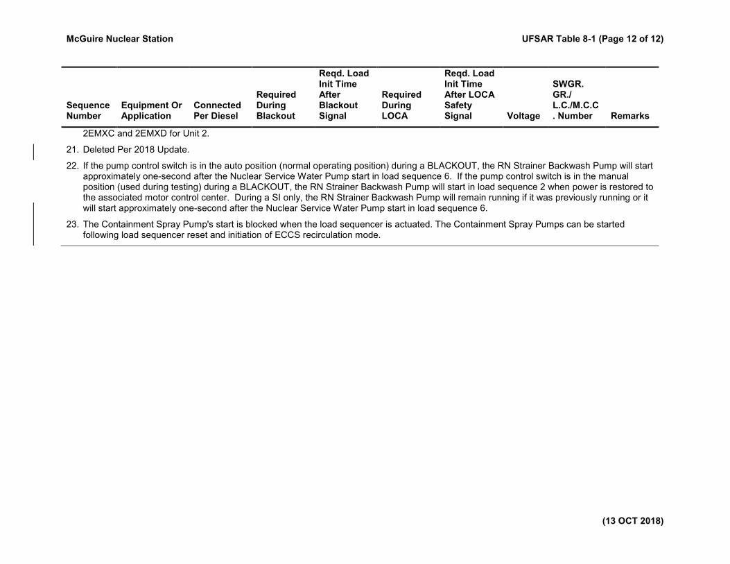
2EMXC and 2EMXD for Unit 2.
21. Deleted Per 2018 Update.
22. If the pump control switch is in the auto position (normal operating position) during a BLACKOUT, the RN Strainer Backwash Pump will start approximately one-second after the Nuclear Service Water Pump start in load sequence 6. If the pump control switch is in the manual position (used during testing) during a BLACKOUT, the RN Strainer Backwash Pump will start in load sequence 2 when power is restored to the associated motor control center. During a SI only, the RN Strainer Backwash Pump will remain running if it was previously running or it will start approximately one-second after the Nuclear Service Water Pump start in load sequence 6.
23. The Containment Spray Pump's start is blocked when the load sequencer is actuated. The Containment Spray Pumps can be started following load sequencer reset and initiation of ECCS recirculation mode.

McGuire Nuclear Station UFSAR Table 8-2 (Page 1 of 1)
(05 APR 2011)
Table 8-2. Single Failure Analysis for the Offsite Power Systems
Component Malfunction Resulting Consequences
1. Duke Energy
Transmission
System
Loss of power due to
blackout
a. The switchyard PCBs connecting the unit
to the system (switchyard) trip
automatically.
b. The onsite diesel generators start and
blackout loads are sequenced on
automatically. The Essential Systems
continue to receive an uninterrupted flow
of power.
2. Switchyard red or
yellow bus
Loss of one a. No consequence. The red or yellow bus
power circuit breakers (as applicable) trip.
The unit is still connected to the system
through two independent circuits from the
remaining switchyard bus.
3. Switchyard power
circuit breakers
connecting the
stepup transformers
to switchyard
or
Circuit from
switchyard to either
main transformer
or
Main transformer
Loss of one due to a
fault
a. The faulted equipment is isolated by
protective relaying and protective
equipment.
b. The other independent offsite circuit
remains unaffected.
c. The two auxiliary switchgears normally
supplied from the faulted circuit are
connected in a rapid bus transfer to the
other auxiliary transformer in the second
independent circuit of that unit within a
maximum of 8 cycles dead time and all
unit and essential auxiliaries continue to
receive uninterrupted offsite power.
d. The unit generator automatically runs
back to 56 percent rated output, or
generator trips.
e. One of the two independent offsite
circuits to each unit is available.
4. Busline circuits
from 230 kV
switchyard to main
transformer or Unit
1.
Collaspe of Rock
Springs Line onto both
busline circuits.
a. The faulted lines are isolated by
protective relaying and protective
equipment..
b. An alternate offsite power source which is
completely independent of the two Unit 1
overhead transmission circuits is provided
through an intertie with the Unit 2 offsite
power system
McGuire Nuclear Station UFSAR Table 8-3 (Page 1 of 1)
(05 APR 2011)
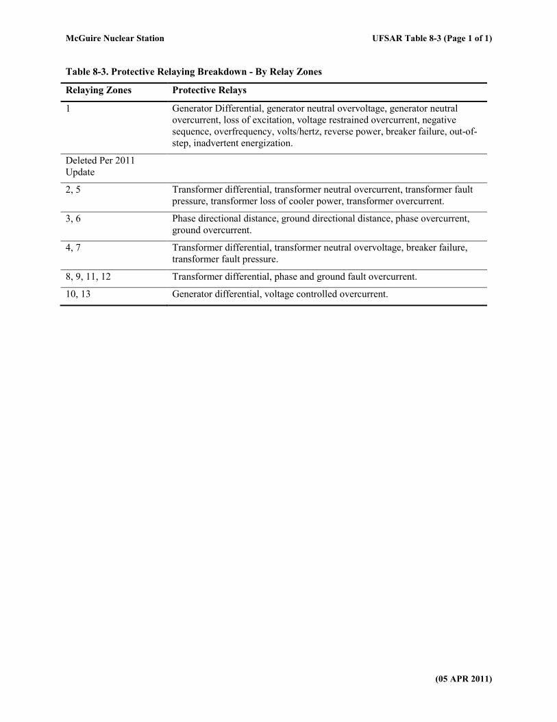
Table 8-3. Protective Relaying Breakdown - By Relay Zones
Relaying Zones Protective Relays
1 Generator Differential, generator neutral overvoltage, generator neutral
overcurrent, loss of excitation, voltage restrained overcurrent, negative
sequence, overfrequency, volts/hertz, reverse power, breaker failure, out-of-
step, inadvertent energization.
Deleted Per 2011
Update
2, 5 Transformer differential, transformer neutral overcurrent, transformer fault
pressure, transformer loss of cooler power, transformer overcurrent.
3, 6 Phase directional distance, ground directional distance, phase overcurrent,
ground overcurrent.
4, 7 Transformer differential, transformer neutral overvoltage, breaker failure,
transformer fault pressure.
8, 9, 11, 12 Transformer differential, phase and ground fault overcurrent.
10, 13 Generator differential, voltage controlled overcurrent.
McGuire Nuclear Station UFSAR Table 8-4 (Page 1 of 4)
(13 OCT 2018)
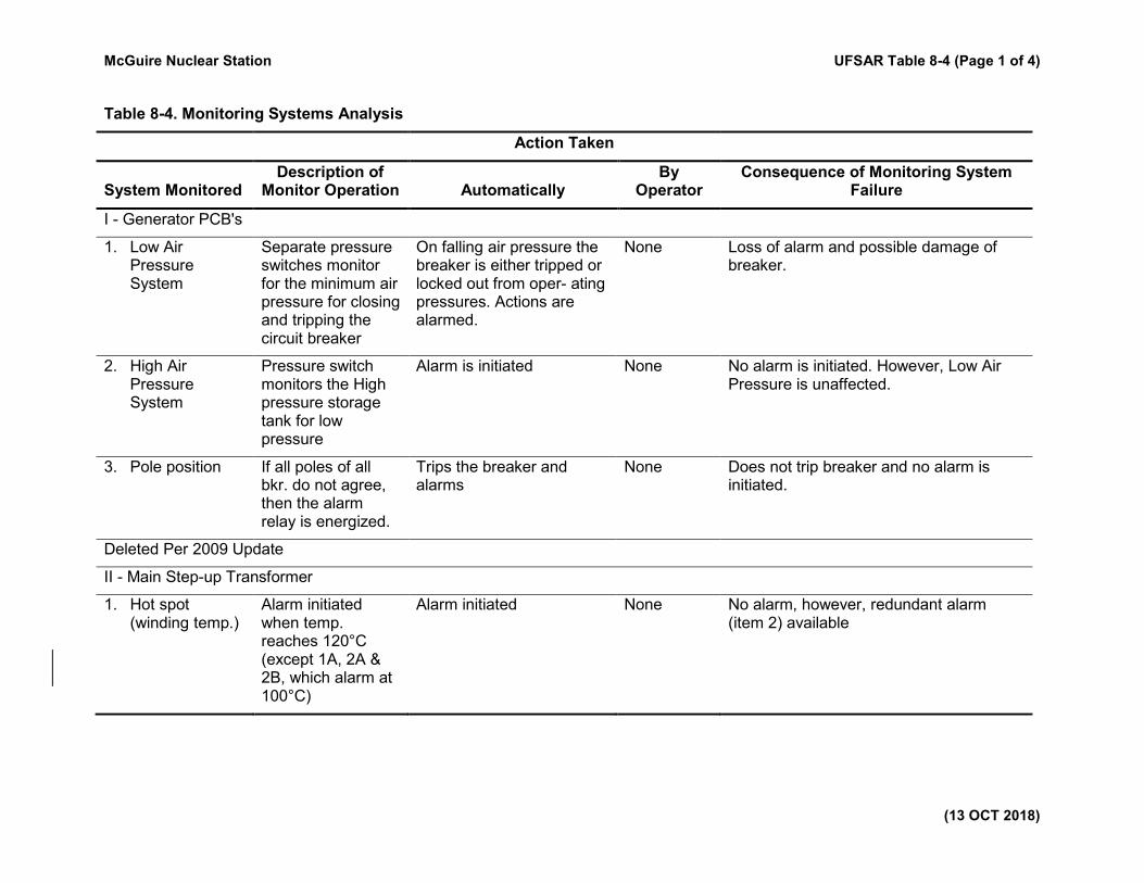
Table 8-4. Monitoring Systems Analysis
Action Taken
System Monitored Description of
Monitor Operation Automatically By
Operator Consequence of Monitoring System
Failure
I - Generator PCB's
1. Low Air Pressure System
Separate pressure switches monitor for the minimum air pressure for closing and tripping the circuit breaker
On falling air pressure the breaker is either tripped or locked out from oper- ating pressures. Actions are alarmed.
None Loss of alarm and possible damage of breaker.
2. High Air Pressure System
Pressure switch monitors the High pressure storage tank for low pressure
Alarm is initiated None No alarm is initiated. However, Low Air Pressure is unaffected.
3. Pole position If all poles of all bkr. do not agree, then the alarm relay is energized.
Trips the breaker and alarms
None Does not trip breaker and no alarm is initiated.
Deleted Per 2009 Update
II - Main Step-up Transformer
1. Hot spot (winding temp.)
Alarm initiated when temp. reaches 120°C (except 1A, 2A & 2B, which alarm at 100°C)
Alarm initiated
None No alarm, however, redundant alarm (item 2) available
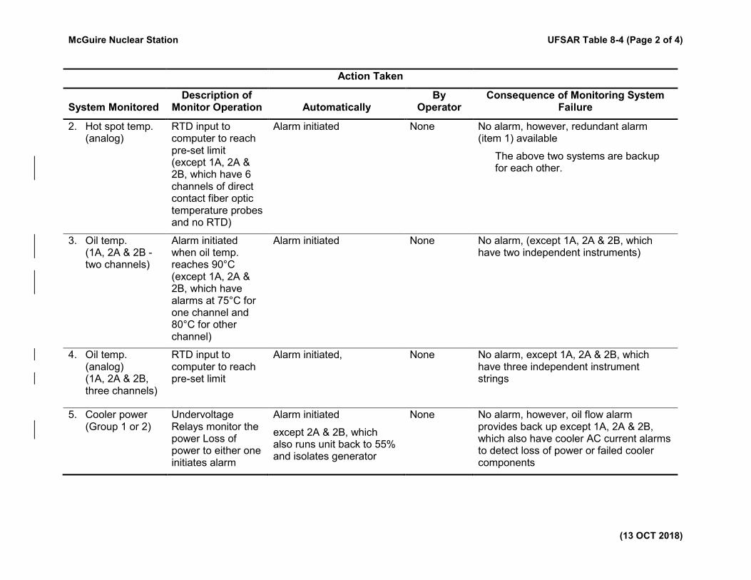
McGuire Nuclear Station UFSAR Table 8-4 (Page 2 of 4)
(13 OCT 2018)
Action Taken
System Monitored Description of
Monitor Operation Automatically By
Operator Consequence of Monitoring System
Failure
2. Hot spot temp. (analog)
RTD input to computer to reach pre-set limit (except 1A, 2A & 2B, which have 6 channels of direct contact fiber optic temperature probes and no RTD)
Alarm initiated
None No alarm, however, redundant alarm (item 1) available
The above two systems are backup for each other.
3. Oil temp. (1A, 2A & 2B - two channels)
Alarm initiated when oil temp. reaches 90°C (except 1A, 2A & 2B, which have alarms at 75°C for one channel and 80°C for other channel)
Alarm initiated
None No alarm, (except 1A, 2A & 2B, which have two independent instruments)
4. Oil temp. (analog) (1A, 2A & 2B, three channels)
RTD input to computer to reach pre-set limit
Alarm initiated, None No alarm, except 1A, 2A & 2B, which have three independent instrument strings
5. Cooler power (Group 1 or 2)
Undervoltage Relays monitor the power Loss of power to either one initiates alarm
Alarm initiated
except 2A & 2B, which also runs unit back to 55% and isolates generator
None No alarm, however, oil flow alarm provides back up except 1A, 2A & 2B, which also have cooler AC current alarms to detect loss of power or failed cooler components

McGuire Nuclear Station UFSAR Table 8-4 (Page 3 of 4)
(13 OCT 2018)
Action Taken
System Monitored Description of
Monitor Operation Automatically By
Operator Consequence of Monitoring System
Failure
6. Cooler power (total loss)
Alarm initiated upon loss of power to both
Alarm initiated
except 2A & 2B, which has the same runback/trip response as item 5
None No alarm, however, oil flow alarm provides back up except 1A, 2A & 2B, which also have cooler AC current alarms to detect loss of power or failed cooler components
7. Mech pressure relief
Alarm initiated due to excess pressure
Alarm initiated None No alarm, however, item 10 provides alarm except: 1A, which has two devices with alarms and 2A & 2B, which have three devices with alarms
8. Oil flow Alarm initiated upon failure of one or more oil pumps.
Alarm initiated None No alarm, however, items 3 and 4 provide alarm except 1A, 2A & 2B, which also have cooler AC current alarms to detect pump failures or obstructions
9. Gas accumulation
Accumulated gas forces oil down to initiate relay
Alarm initiated None No alarm, however, covered under maintenance procedures except 1A which has one channel of detection and 2A & 2B, which have two channels of detection. Item 12 also provides backup.
10. Fault Pressure Contact closure upon sudden rise of transformer internal pressure
Trip the transformer off and initiate alarm
None No trip from fault pressure relay, however, items 7 and 9 provide alarm. 1A, 2A & 2B, have three alarming sensors, with 2 out of 3 logic to operate trip.
11. Oil level Contact closure when the oil level reaches the lowest safe level
Trip the transformer off and initiate alarm
None No trip from oil level switch.
1A, 2A & 2B, each have three alarming sensors, with 2 out of 3 logic to operate trip.
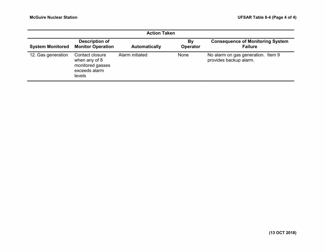
McGuire Nuclear Station UFSAR Table 8-4 (Page 4 of 4)
(13 OCT 2018)
Action Taken
System Monitored Description of
Monitor Operation Automatically By
Operator Consequence of Monitoring System
Failure
12. Gas generation Contact closure when any of 8 monitored gasses exceeds alarm levels
Alarm initiated None No alarm on gas generation. Item 9 provides backup alarm.
McGuire Nuclear Station UFSAR Table 8-5 (Page 1 of 1)
(14 OCT 2000)
Table 8-5. Deleted Per 1999 Update
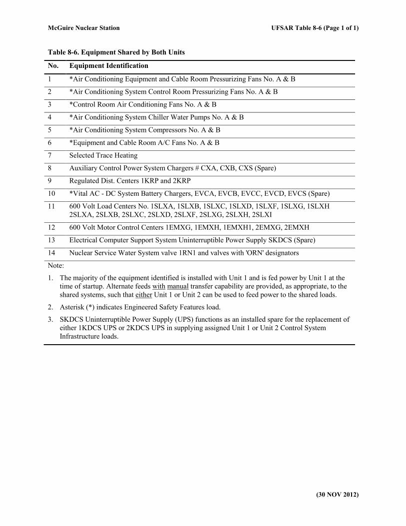
McGuire Nuclear Station UFSAR Table 8-6 (Page 1 of 1)
(30 NOV 2012)
Table 8-6. Equipment Shared by Both Units
No. Equipment Identification
1 *Air Conditioning Equipment and Cable Room Pressurizing Fans No. A & B
2 *Air Conditioning System Control Room Pressurizing Fans No. A & B
3 *Control Room Air Conditioning Fans No. A & B
4 *Air Conditioning System Chiller Water Pumps No. A & B
5 *Air Conditioning System Compressors No. A & B
6 *Equipment and Cable Room A/C Fans No. A & B
7 Selected Trace Heating
8 Auxiliary Control Power System Chargers # CXA, CXB, CXS (Spare)
9 Regulated Dist. Centers 1KRP and 2KRP
10 *Vital AC - DC System Battery Chargers, EVCA, EVCB, EVCC, EVCD, EVCS (Spare)
11 600 Volt Load Centers No. 1SLXA, 1SLXB, 1SLXC, 1SLXD, 1SLXF, 1SLXG, 1SLXH
2SLXA, 2SLXB, 2SLXC, 2SLXD, 2SLXF, 2SLXG, 2SLXH, 2SLXI
12 600 Volt Motor Control Centers 1EMXG, 1EMXH, 1EMXH1, 2EMXG, 2EMXH
13 Electrical Computer Support System Uninterruptible Power Supply SKDCS (Spare)
14 Nuclear Service Water System valve 1RN1 and valves with 'ORN' designators
Note:
1. The majority of the equipment identified is installed with Unit 1 and is fed power by Unit 1 at the
time of startup. Alternate feeds with manual transfer capability are provided, as appropriate, to the
shared systems, such that either Unit 1 or Unit 2 can be used to feed power to the shared loads.
2. Asterisk (*) indicates Engineered Safety Features load.
3. SKDCS Uninterruptible Power Supply (UPS) functions as an installed spare for the replacement of
either 1KDCS UPS or 2KDCS UPS in supplying assigned Unit 1 or Unit 2 Control System
Infrastructure loads.
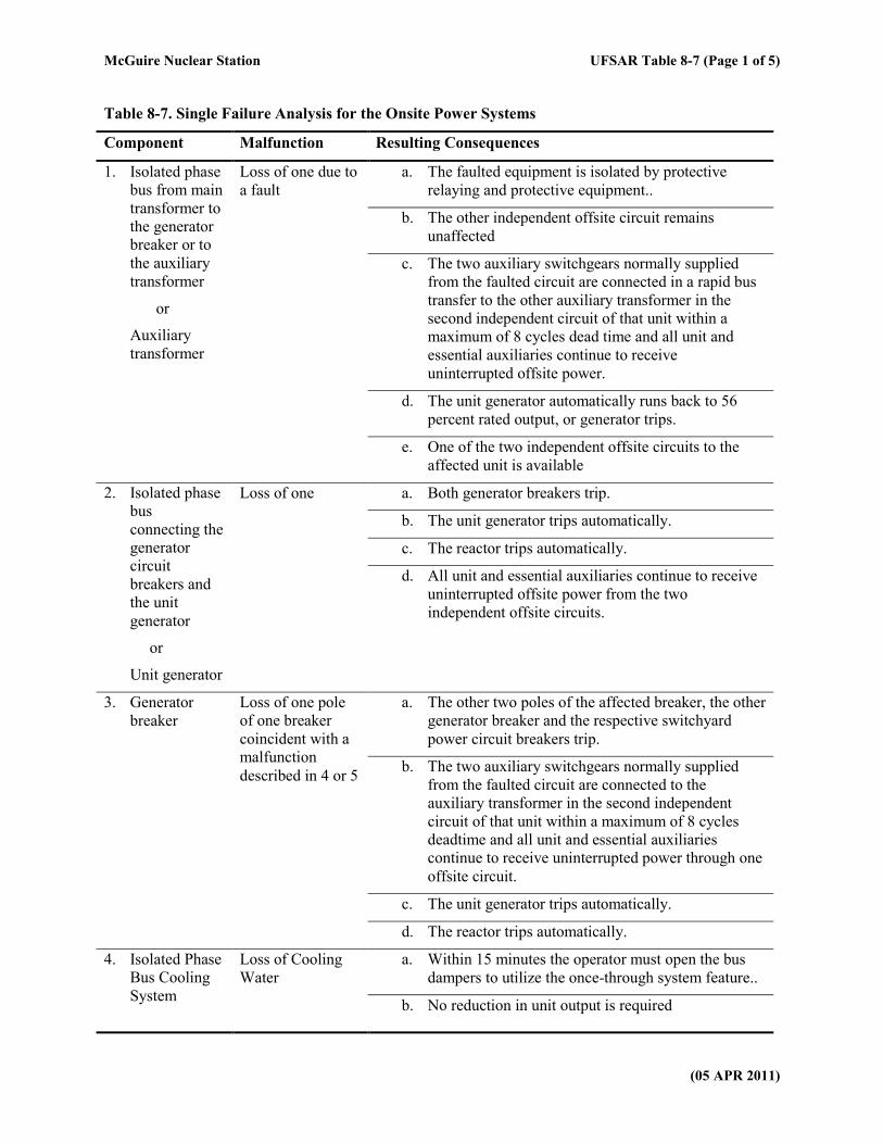
McGuire Nuclear Station UFSAR Table 8-7 (Page 1 of 5)
(05 APR 2011)
Table 8-7. Single Failure Analysis for the Onsite Power Systems
Component Malfunction Resulting Consequences
1. Isolated phase
bus from main
transformer to
the generator
breaker or to
the auxiliary
transformer
or
Auxiliary
transformer
Loss of one due to
a fault
a. The faulted equipment is isolated by protective
relaying and protective equipment..
b. The other independent offsite circuit remains
unaffected
c. The two auxiliary switchgears normally supplied
from the faulted circuit are connected in a rapid bus
transfer to the other auxiliary transformer in the
second independent circuit of that unit within a
maximum of 8 cycles dead time and all unit and
essential auxiliaries continue to receive
uninterrupted offsite power.
d. The unit generator automatically runs back to 56
percent rated output, or generator trips.
e. One of the two independent offsite circuits to the
affected unit is available
2. Isolated phase
bus
connecting the
generator
circuit
breakers and
the unit
generator
or
Unit generator
Loss of one a. Both generator breakers trip.
b. The unit generator trips automatically.
c. The reactor trips automatically.
d. All unit and essential auxiliaries continue to receive
uninterrupted offsite power from the two
independent offsite circuits.
3. Generator
breaker
Loss of one pole
of one breaker
coincident with a
malfunction
described in 4 or 5
a. The other two poles of the affected breaker, the other
generator breaker and the respective switchyard
power circuit breakers trip.
b. The two auxiliary switchgears normally supplied
from the faulted circuit are connected to the
auxiliary transformer in the second independent
circuit of that unit within a maximum of 8 cycles
deadtime and all unit and essential auxiliaries
continue to receive uninterrupted power through one
offsite circuit.
c. The unit generator trips automatically.
d. The reactor trips automatically.
4. Isolated Phase
Bus Cooling
System
Loss of Cooling
Water
a. Within 15 minutes the operator must open the bus
dampers to utilize the once-through system feature..
b. No reduction in unit output is required
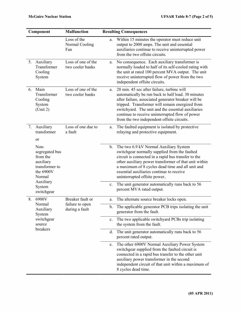
McGuire Nuclear Station UFSAR Table 8-7 (Page 2 of 5)
(05 APR 2011)
Component Malfunction Resulting Consequences
Loss of the
Normal Cooling
Fan
a. Within 15 minutes the operator must reduce unit
output to 2000 amps. The unit and essential
auxiliaries continue to receive uninterrupted power
from the two offsite circuits.
5. Auxiliary
Transformer
Cooling
System
Loss of one of the
two cooler banks
a. No consequence. Each auxiliary transformer is
normally loaded to half of its self-cooled rating with
the unit at rated 100 percent MVA output. The unit
receive uninterrupted flow of power from the two
independent offsite circuits.
6. Main
Transformer
Cooling
System
(Unit 2)
Loss of one of the
two cooler banks
a. 28 min. 45 sec after failure, turbine will
automatically be run back to half load. 30 minutes
after failure, associated generator breaker will be
tripped. Transformer will remain energized from
switchyard. The unit and the essential auxiliaries
continue to receive uninterrupted flow of power
from the two independent offsite circuits.
7. Auxiliary
transformer
or
Loss of one due to
a fault
a. The faulted equipment is isolated by protective
relaying and protective equipment.
Non-
segregated bus
from the
auxiliary
transformer to
the 6900V
Normal
Auxiliary
System
switchgear
b. The two 6.9 kV Normal Auxiliary System
switchgear normally supplied from the faulted
circuit is connected in a rapid bus transfer to the
other auxiliary power transformer of that unit within
a maximum of 8 cycles dead time and all unit and
essential auxiliaries continue to receive
uninterrupted offsite power..
c. The unit generator automatically runs back to 56
percent MVA rated output.
8. 6900V
Normal
Auxiliary
System
switchgear
source
breakers
Breaker fault or
failure to open
during a fault
a. The alternate source breaker locks open.
b. The applicable generator PCB trips isolating the unit
generator from the fault.
c. The two applicable switchyard PCBs trip isolating
the system from the fault.
d. The unit generator automatically runs back to 56
percent rated output.
e. The other 6900V Normal Auxiliary Power System
switchgear supplied from the faulted circuit is
connected in a rapid bus transfer to the other unit
auxiliary power transformer in the second
independent circuit of that unit within a maximum of
8 cycles dead time.
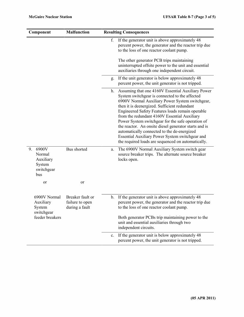
McGuire Nuclear Station UFSAR Table 8-7 (Page 3 of 5)
(05 APR 2011)
Component Malfunction Resulting Consequences
f. If the generator unit is above approximately 48
percent power, the generator and the reactor trip due
to the loss of one reactor coolant pump.
The other generator PCB trips maintaining
uninterrupted offsite power to the unit and essential
auxiliaries through one independent circuit.
g. If the unit generator is below approximately 48
percent power, the unit generator is not tripped.
h. Assuming that one 4160V Essential Auxiliary Power
System switchgear is connected to the affected
6900V Normal Auxiliary Power System switchgear,
then it is deenergized. Sufficient redundant
Engineered Safety Features loads remain operable
from the redundant 4160V Essential Auxiliary
Power System switchgear for the safe operation of
the reactor. An onsite diesel generator starts and is
automatically connected to the de-energized
Essential Auxiliary Power System switchgear and
the required loads are sequenced on automatically.
9. 6900V
Normal
Auxiliary
System
switchgear
bus
Bus shorted a. The 6900V Normal Auxiliary System switch gear
source breaker trips. The alternate source breaker
locks open.
or
or
6900V Normal
Auxiliary
System
switchgear
feeder breakers
Breaker fault or
failure to open
during a fault
b. If the generator unit is above approximately 48
percent power, the generator and the reactor trip due
to the loss of one reactor coolant pump.
Both generator PCBs trip maintaining power to the
unit and essential auxiliaries through two
independent circuits.
c. If the generator unit is below approximately 48
percent power, the unit generator is not tripped.
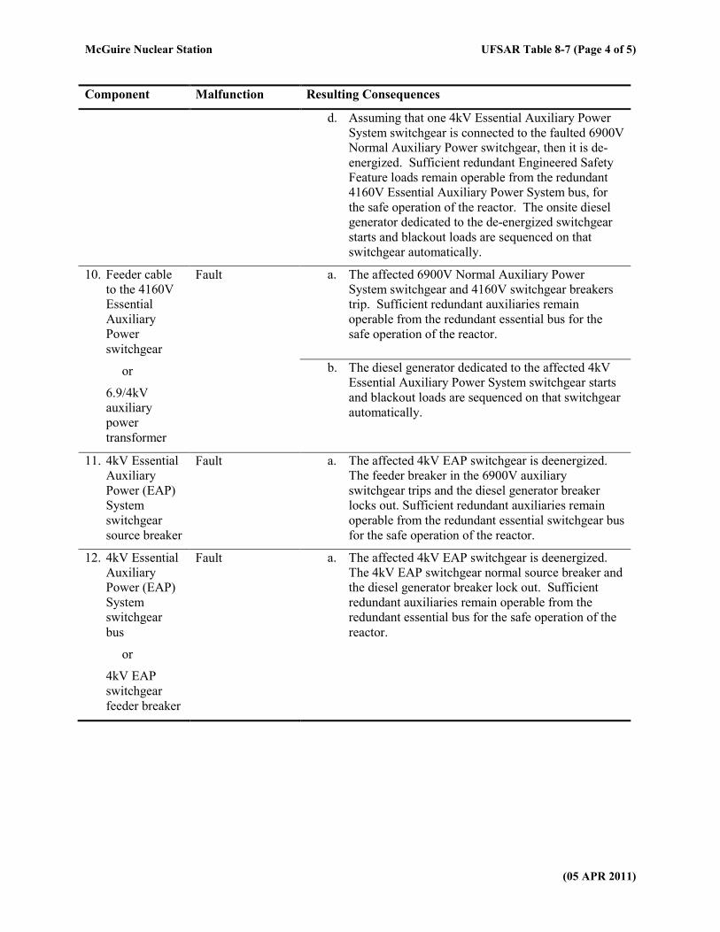
McGuire Nuclear Station UFSAR Table 8-7 (Page 4 of 5)
(05 APR 2011)
Component Malfunction Resulting Consequences
d. Assuming that one 4kV Essential Auxiliary Power
System switchgear is connected to the faulted 6900V
Normal Auxiliary Power switchgear, then it is de-
energized. Sufficient redundant Engineered Safety
Feature loads remain operable from the redundant
4160V Essential Auxiliary Power System bus, for
the safe operation of the reactor. The onsite diesel
generator dedicated to the de-energized switchgear
starts and blackout loads are sequenced on that
switchgear automatically.
10. Feeder cable
to the 4160V
Essential
Auxiliary
Power
switchgear
or
6.9/4kV
auxiliary
power
transformer
Fault a. The affected 6900V Normal Auxiliary Power
System switchgear and 4160V switchgear breakers
trip. Sufficient redundant auxiliaries remain
operable from the redundant essential bus for the
safe operation of the reactor.
b. The diesel generator dedicated to the affected 4kV
Essential Auxiliary Power System switchgear starts
and blackout loads are sequenced on that switchgear
automatically.
11. 4kV Essential
Auxiliary
Power (EAP)
System
switchgear
source breaker
Fault a. The affected 4kV EAP switchgear is deenergized.
The feeder breaker in the 6900V auxiliary
switchgear trips and the diesel generator breaker
locks out. Sufficient redundant auxiliaries remain
operable from the redundant essential switchgear bus
for the safe operation of the reactor.
12. 4kV Essential
Auxiliary
Power (EAP)
System
switchgear
bus
or
4kV EAP
switchgear
feeder breaker
Fault a. The affected 4kV EAP switchgear is deenergized.
The 4kV EAP switchgear normal source breaker and
the diesel generator breaker lock out. Sufficient
redundant auxiliaries remain operable from the
redundant essential bus for the safe operation of the
reactor.
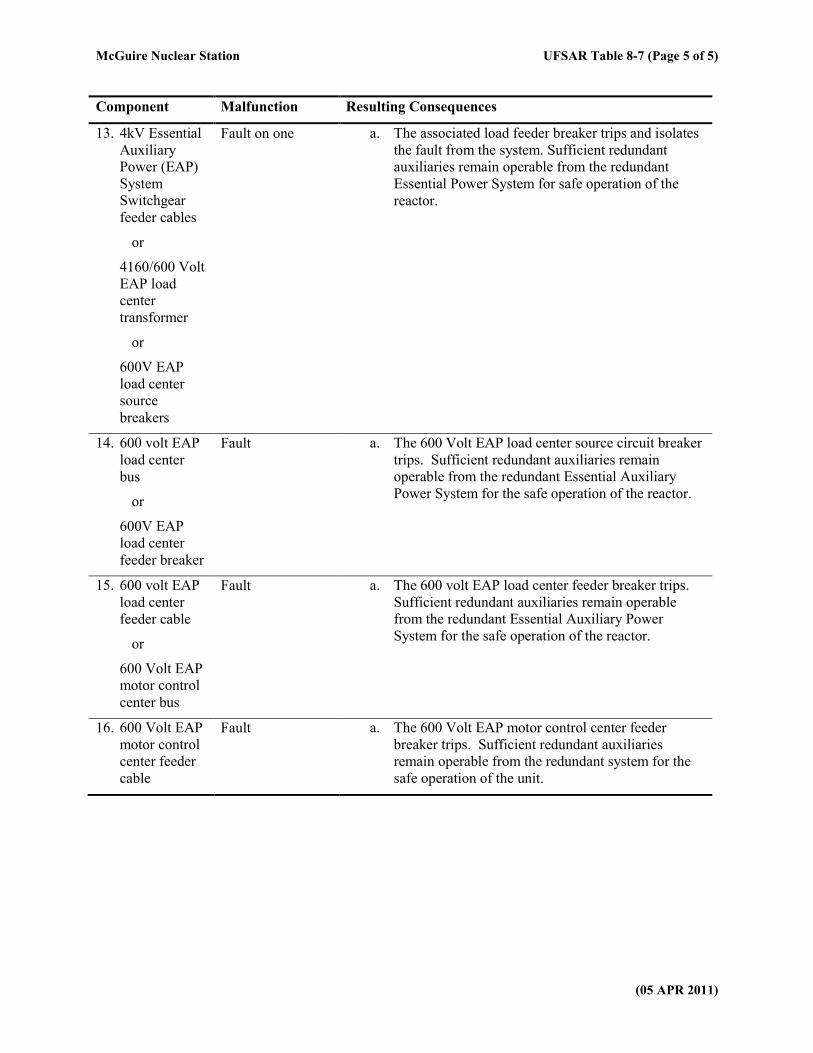
McGuire Nuclear Station UFSAR Table 8-7 (Page 5 of 5)
(05 APR 2011)
Component Malfunction Resulting Consequences
13. 4kV Essential
Auxiliary
Power (EAP)
System
Switchgear
feeder cables
or
4160/600 Volt
EAP load
center
transformer
or
600V EAP
load center
source
breakers
Fault on one a. The associated load feeder breaker trips and isolates
the fault from the system. Sufficient redundant
auxiliaries remain operable from the redundant
Essential Power System for safe operation of the
reactor.
14. 600 volt EAP
load center
bus
or
600V EAP
load center
feeder breaker
Fault a. The 600 Volt EAP load center source circuit breaker
trips. Sufficient redundant auxiliaries remain
operable from the redundant Essential Auxiliary
Power System for the safe operation of the reactor.
15. 600 volt EAP
load center
feeder cable
or
600 Volt EAP
motor control
center bus
Fault a. The 600 volt EAP load center feeder breaker trips.
Sufficient redundant auxiliaries remain operable
from the redundant Essential Auxiliary Power
System for the safe operation of the reactor.
16. 600 Volt EAP
motor control
center feeder
cable
Fault a. The 600 Volt EAP motor control center feeder
breaker trips. Sufficient redundant auxiliaries
remain operable from the redundant system for the
safe operation of the unit.
McGuire Nuclear Station UFSAR Table 8-8 (Page 1 of 1)
(13 OCT 2018)
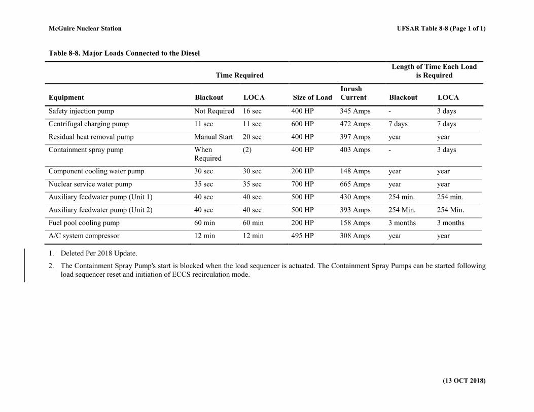
Table 8-8. Major Loads Connected to the Diesel
Time Required
Length of Time Each Load
is Required
Equipment Blackout LOCA Size of Load
Inrush
Current Blackout LOCA
Safety injection pump Not Required 16 sec 400 HP 345 Amps - 3 days
Centrifugal charging pump 11 sec 11 sec 600 HP 472 Amps 7 days 7 days
Residual heat removal pump Manual Start 20 sec 400 HP 397 Amps year year
Containment spray pump When
Required
(2) 400 HP 403 Amps - 3 days
Component cooling water pump 30 sec 30 sec 200 HP 148 Amps year year
Nuclear service water pump 35 sec 35 sec 700 HP 665 Amps year year
Auxiliary feedwater pump (Unit 1) 40 sec 40 sec 500 HP 430 Amps 254 min. 254 min.
Auxiliary feedwater pump (Unit 2) 40 sec 40 sec 500 HP 393 Amps 254 Min. 254 Min.
Fuel pool cooling pump 60 min 60 min 200 HP 158 Amps 3 months 3 months
A/C system compressor 12 min 12 min 495 HP 308 Amps year year
1. Deleted Per 2018 Update.
2. The Containment Spray Pump's start is blocked when the load sequencer is actuated. The Containment Spray Pumps can be started following
load sequencer reset and initiation of ECCS recirculation mode.
McGuire Nuclear Station UFSAR Table 8-9 (Page 1 of 1)
(14 OCT 2000)
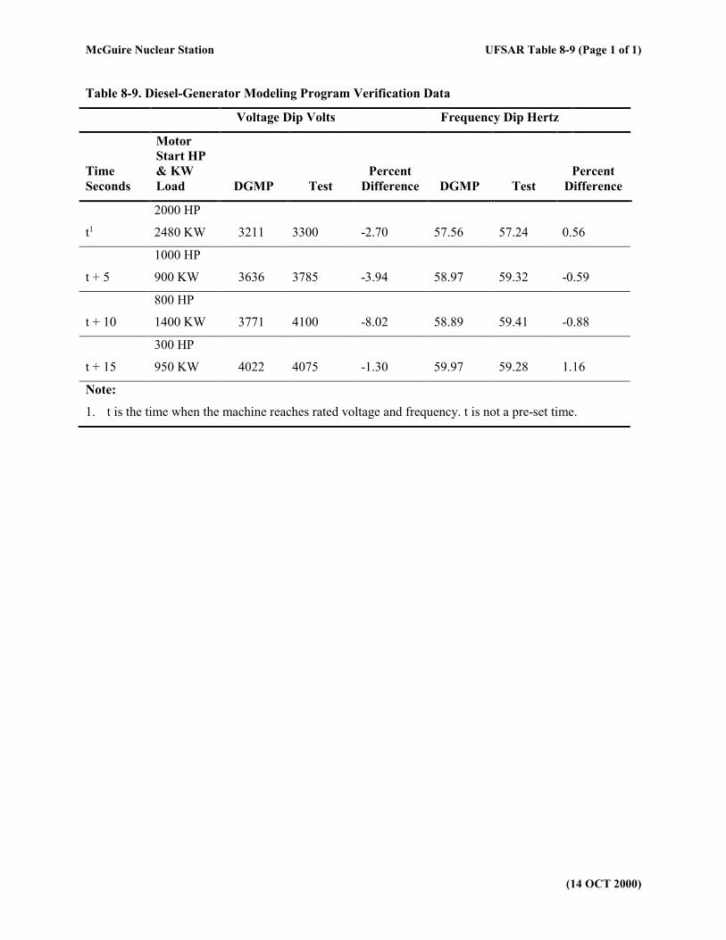
Table 8-9. Diesel-Generator Modeling Program Verification Data
Voltage Dip Volts Frequency Dip Hertz
Time
Seconds
Motor
Start HP
& KW
Load DGMP Test
Percent
Difference DGMP Test
Percent
Difference
t1
2000 HP
2480 KW 3211 3300 -2.70 57.56 57.24 0.56
t + 5
1000 HP
900 KW 3636 3785 -3.94 58.97 59.32 -0.59
t + 10
800 HP
1400 KW 3771 4100 -8.02 58.89 59.41 -0.88
t + 15
300 HP
950 KW 4022 4075 -1.30 59.97 59.28 1.16
Note:
1. t is the time when the machine reaches rated voltage and frequency. t is not a pre-set time.
McGuire Nuclear Station UFSAR Table 8-10 (Page 1 of 2)
(14 OCT 2000)
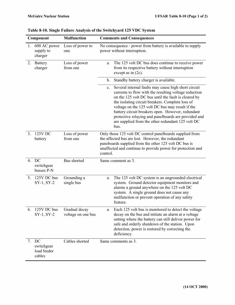
Table 8-10. Single Failure Analysis of the Switchyard 125 VDC System
Component Malfunction Comments and Consequences
1. 600 AC power
supply to
charger
Loss of power to
one
No consequence - power from battery is available to supply
power without interruption.
2. Battery
charger
Loss of power
from one
a. The 125 volt DC bus does continue to receive power
from its respective battery without interruption
except as in (2c).
b. Standby battery charger is available.
c. Several internal faults may cause high short circuit
currents to flow with the resulting voltage reduction
on the 125 volt DC bus until the fault is cleared by
the isolating circuit breakers. Complete loss of
voltage on the 125 volt DC bus may result if the
battery circuit breakers open. However, redundant
protective relaying and panelboards are provided and
are supplied from the other redundant 125 volt DC
bus.
3. 125V DC
battery
Loss of power
from one
Only those 125 volt DC control panelboards supplied from
the affected bus are lost. However, the redundant
paneboards supplied from the other 125 volt DC bus is
unaffected and continue to provide power for protection and
control.
4. DC
switchgear
busses P-N
Bus shorted Same comment as 3.
5. 125V DC bus
SY-1, SY-2
Grounding a
single bus
a. The 125 volt DC system is an ungrounded electrical
system. Ground detector equipment monitors and
alarms a ground anywhere on the 125 volt DC
system. A single ground does not cause any
malfunction or prevent operation of any safety
feature.
6. 125V DC bus
SY-1, SY-2
Gradual decay
voltage on one bus
a. Each 125 volt bus is monitored to detect the voltage
decay on the bus and initiate an alarm at a voltage
setting where the battery can still deliver power for
safe and orderly shutdown of the station. Upon
detection, power is restored by correcting the
deficiency.
7. DC
switchgear
load feeder
cables
Cables shorted Same comments as 3.
McGuire Nuclear Station UFSAR Table 8-10 (Page 2 of 2)
(14 OCT 2000)
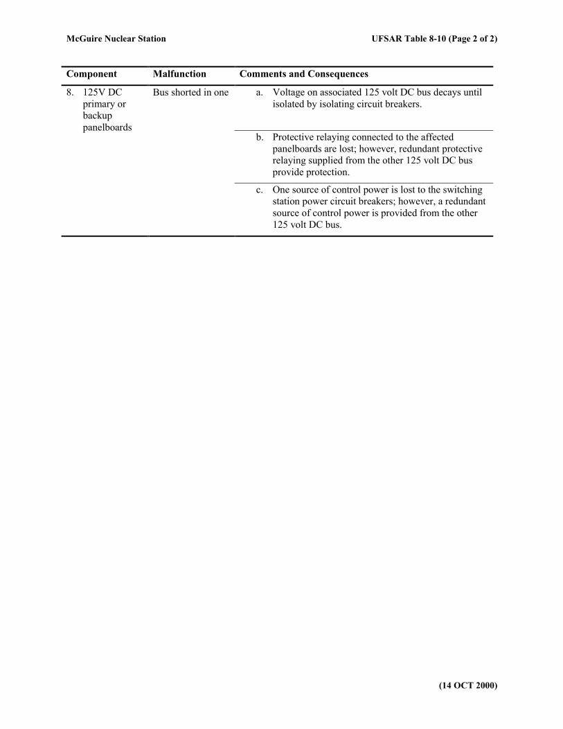
Component Malfunction Comments and Consequences
8. 125V DC
primary or
backup
panelboards
Bus shorted in one a. Voltage on associated 125 volt DC bus decays until
isolated by isolating circuit breakers.
b. Protective relaying connected to the affected
panelboards are lost; however, redundant protective
relaying supplied from the other 125 volt DC bus
provide protection.
c. One source of control power is lost to the switching
station power circuit breakers; however, a redundant
source of control power is provided from the other
125 volt DC bus.

McGuire Nuclear Station UFSAR Table 8-11 (Page 1 of 1)
(09 OCT 2015)
Table 8-11. 250 VDC Auxiliary Power System Loads Used for Battery Sizing1
Load Rating of Load Total Amperes Inrush/Continuous
Turbine emergency bearing oil pump motor
75 HP 783/261
Deleted per 2015 update
Unit 1 (only) Generator air side seal oil backup pump motor
25 HP 270/90
Unit 2 (only) Seal oil pump motor
15 HP 202.7/51.2
Feedwater pump turbine No. 1A emergency oil pump motor
7.5 HP 87/29
Feedwater pump turbine No 1B emergency oil pump motor
7.5 HP 87/29
Lighting (U1&U2) and seal oil starter motor monitoring (Unit 2 only)
203.4/203.4
Bus Voltage & System Failure Circuits
2/2
Turbine Backup Vapor Extractor
1.5 HP 17.25/5.75
Note:
1. Batteries are sized to supply seal oil pump, vapor extractor and remaining DC lights for four hours along with the FWPT Emergency Oil (backup) Pumps (EOPs) which run for three hours, provided the Reactor Bldg. and Admin. Bldg. DC lights are removed within two hours. Loads on Unit 1 and 2 are similar except as noted.
McGuire Nuclear Station UFSAR Table 8-12 (Page 1 of 1)
(14 OCT 2000)
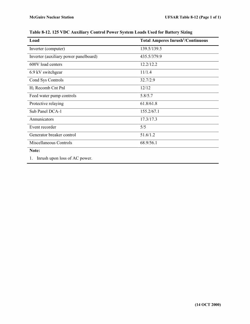
Table 8-12. 125 VDC Auxiliary Control Power System Loads Used for Battery Sizing
Load Total Amperes Inrush1/Continuous
Inverter (computer) 139.5/139.5
Inverter (auxiliary power panelboard) 435.5/379.9
600V load centers 12.2/12.2
6.9 kV switchgear 11/1.4
Cond Sys Controls 32.7/2.9
H2 Recomb Cnt Pnl 12/12
Feed water pump controls 5.8/5.7
Protective relaying 61.8/61.8
Sub Panel DCA-1 155.2/67.1
Annunicators 17.3/17.3
Event recorder 5/5
Generator breaker control 51.6/1.2
Miscellaneous Controls 68.9/56.1
Note:
1. Inrush upon loss of AC power.
McGuire Nuclear Station UFSAR Table 8-13 (Page 1 of 2)
(14 OCT 2000)
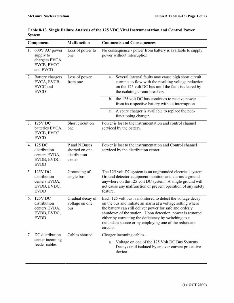
Table 8-13. Single Failure Analysis of the 125 VDC Vital Instrumentation and Control Power
System
Component Malfunction Comments and Consequences
1. 600V AC power
supply to
chargers EVCA,
EVCB, EVCC
and EVCD
Loss of power to
one
No consequence - power from battery is available to supply
power without interruption.
2. Battery chargers
EVCA, EVCB,
EVCC and
EVCD
Loss of power
from one
a. Several internal faults may cause high short circuit
currents to flow with the resulting voltage reduction
on the 125 volt DC bus until the fault is cleared by
the isolating circuit breakers.
b. the 125 volt DC bus continues to receive power
from its respective battery without interruption
c. A spare charger is available to replace the non-
functioning charger.
3. 125V DC
batteries EVCA,
EVCB, EVCC
EVCD
Short circuit on
one
Power is lost to the instrumentation and control channel
serviced by the battery.
4. 125 DC
distribution
centers EVDA,
EVDB, EVDC,
EVDD
P and N Buses
shorted on one
distribution
center
Power is lost to the instrumentation and Control channel
serviced by the distribution center.
5. 125V DC
distribution
centers EVDA,
EVDB, EVDC,
EVDD
Grounding of
single bus
The 125 volt DC system is an ungrounded electrical system.
Ground detector equipment monitors and alarms a ground
anywhere on the 125 volt DC system. A single ground will
not cause any malfunction or prevent operation of any safety
feature.
6. 125V DC
distribution
centers EVDA,
EVDB, EVDC,
EVDD
Gradual decay of
voltage on one
bus
Each 125 volt bus is monitored to detect the voltage decay
on the bus and initiate an alarm at a voltage setting where
the battery can still deliver power for safe and orderly
shutdown of the station. Upon detection, power is restored
either by correcting the deficiency by switching to a
redundant source or by employing one of the redundant
circuits.
7. DC distribution
center incoming
feeder cables
Cables shorted Charger incoming cables -
a. Voltage on one of the 125 Volt DC Bus Systems
Decays until isolated by an over current protective
device.
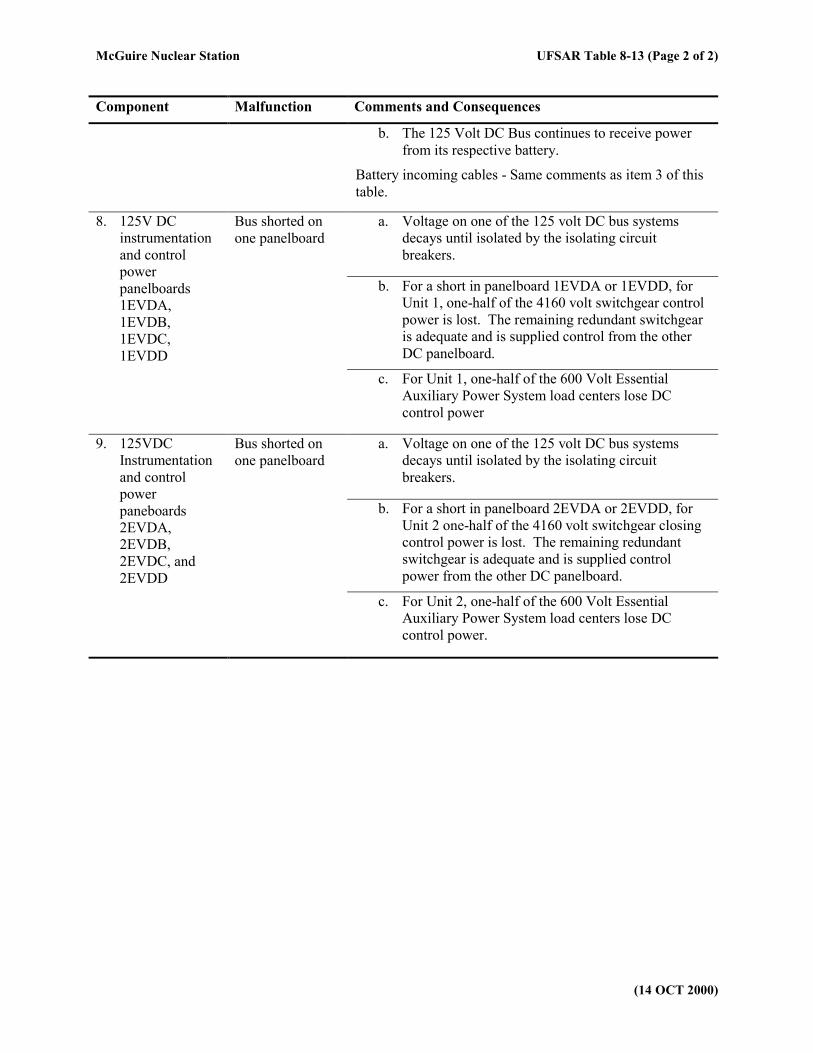
McGuire Nuclear Station UFSAR Table 8-13 (Page 2 of 2)
(14 OCT 2000)
Component Malfunction Comments and Consequences
b. The 125 Volt DC Bus continues to receive power
from its respective battery.
Battery incoming cables - Same comments as item 3 of this
table.
8. 125V DC
instrumentation
and control
power
panelboards
1EVDA,
1EVDB,
1EVDC,
1EVDD
Bus shorted on
one panelboard
a. Voltage on one of the 125 volt DC bus systems
decays until isolated by the isolating circuit
breakers.
b. For a short in panelboard 1EVDA or 1EVDD, for
Unit 1, one-half of the 4160 volt switchgear control
power is lost. The remaining redundant switchgear
is adequate and is supplied control from the other
DC panelboard.
c. For Unit 1, one-half of the 600 Volt Essential
Auxiliary Power System load centers lose DC
control power
9. 125VDC
Instrumentation
and control
power
paneboards
2EVDA,
2EVDB,
2EVDC, and
2EVDD
Bus shorted on
one panelboard
a. Voltage on one of the 125 volt DC bus systems
decays until isolated by the isolating circuit
breakers.
b. For a short in panelboard 2EVDA or 2EVDD, for
Unit 2 one-half of the 4160 volt switchgear closing
control power is lost. The remaining redundant
switchgear is adequate and is supplied control
power from the other DC panelboard.
c. For Unit 2, one-half of the 600 Volt Essential
Auxiliary Power System load centers lose DC
control power.
McGuire Nuclear Station UFSAR Table 8-14 (Page 1 of 1)
(14 OCT 2000)
Table 8-14. Deleted Per 1991 Update. The information is available in Figure 8-39
McGuire Nuclear Station UFSAR Table 8-15 (Page 1 of 1)
(14 OCT 2000)
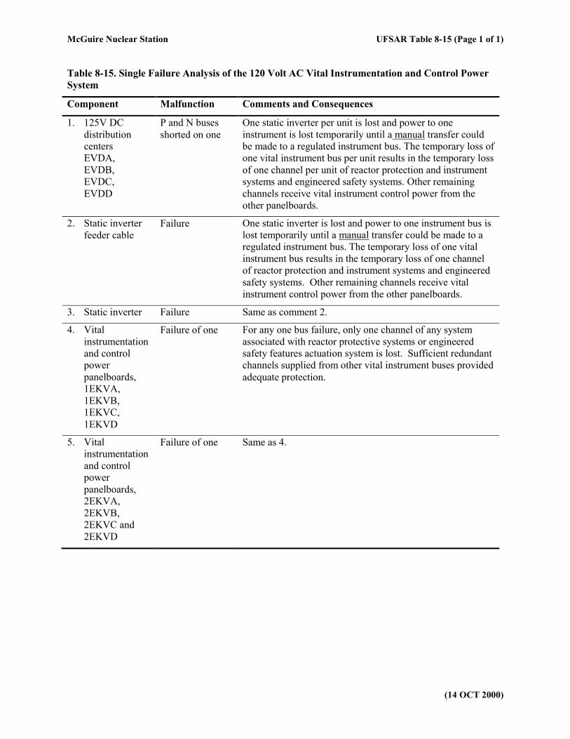
Table 8-15. Single Failure Analysis of the 120 Volt AC Vital Instrumentation and Control Power
System
Component Malfunction Comments and Consequences
1. 125V DC
distribution
centers
EVDA,
EVDB,
EVDC,
EVDD
P and N buses
shorted on one
One static inverter per unit is lost and power to one
instrument is lost temporarily until a manual transfer could
be made to a regulated instrument bus. The temporary loss of
one vital instrument bus per unit results in the temporary loss
of one channel per unit of reactor protection and instrument
systems and engineered safety systems. Other remaining
channels receive vital instrument control power from the
other panelboards.
2. Static inverter
feeder cable
Failure One static inverter is lost and power to one instrument bus is
lost temporarily until a manual transfer could be made to a
regulated instrument bus. The temporary loss of one vital
instrument bus results in the temporary loss of one channel
of reactor protection and instrument systems and engineered
safety systems. Other remaining channels receive vital
instrument control power from the other panelboards.
3. Static inverter Failure Same as comment 2.
4. Vital
instrumentation
and control
power
panelboards,
1EKVA,
1EKVB,
1EKVC,
1EKVD
Failure of one For any one bus failure, only one channel of any system
associated with reactor protective systems or engineered
safety features actuation system is lost. Sufficient redundant
channels supplied from other vital instrument buses provided
adequate protection.
5. Vital
instrumentation
and control
power
panelboards,
2EKVA,
2EKVB,
2EKVC and
2EKVD
Failure of one Same as 4.
McGuire Nuclear Station UFSAR Table 8-16 (Page 1 of 1)
(14 OCT 2000)
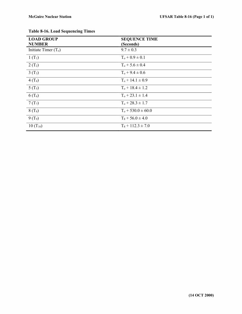
Table 8-16. Load Sequencing Times
LOAD GROUP
NUMBER
SEQUENCE TIME
(Seconds)
Initiate Timer (To) 9.7 ± 0.3
1 (T1) To + 0.9 ± 0.1
2 (T2) To + 5.6 ± 0.4
3 (T3) To + 9.4 ± 0.6
4 (T4) To + 14.1 ± 0.9
5 (T5) To + 18.4 ± 1.2
6 (T6) To + 23.1 ± 1.4
7 (T7) To + 28.3 ± 1.7
8 (T8) To + 530.0 ± 60.0
9 (T9) T8 + 56.0 ± 4.0
10 (T10) T8 + 112.3 ± 7.0
McGuire Nuclear Station UFSAR Table 8-17 (Page 1 of 6)
(27 MAR 2002)
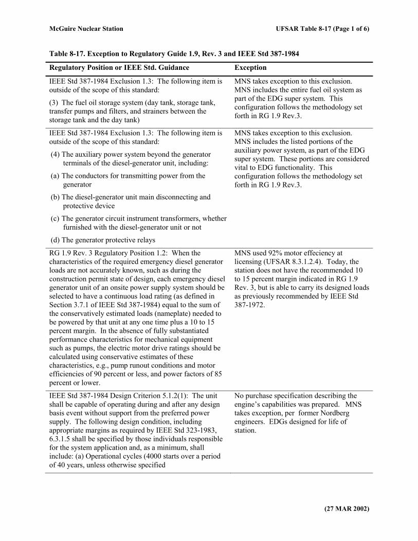
Table 8-17. Exception to Regulatory Guide 1.9, Rev. 3 and IEEE Std 387-1984
Regulatory Position or IEEE Std. Guidance Exception
IEEE Std 387-1984 Exclusion 1.3: The following item is
outside of the scope of this standard:
(3) The fuel oil storage system (day tank, storage tank,
transfer pumps and filters, and strainers between the
storage tank and the day tank)
MNS takes exception to this exclusion.
MNS includes the entire fuel oil system as
part of the EDG super system. This
configuration follows the methodology set
forth in RG 1.9 Rev.3.
IEEE Std 387-1984 Exclusion 1.3: The following item is
outside of the scope of this standard:
(4) The auxiliary power system beyond the generator
terminals of the diesel-generator unit, including:
(a) The conductors for transmitting power from the
generator
(b) The diesel-generator unit main disconnecting and
protective device
(c) The generator circuit instrument transformers, whether
furnished with the diesel-generator unit or not
(d) The generator protective relays
MNS takes exception to this exclusion.
MNS includes the listed portions of the
auxiliary power system, as part of the EDG
super system. These portions are considered
vital to EDG functionality. This
configuration follows the methodology set
forth in RG 1.9 Rev.3.
RG 1.9 Rev. 3 Regulatory Position 1.2: When the
characteristics of the required emergency diesel generator
loads are not accurately known, such as during the
construction permit state of design, each emergency diesel
generator unit of an onsite power supply system should be
selected to have a continuous load rating (as defined in
Section 3.7.1 of IEEE Std 387-1984) equal to the sum of
the conservatively estimated loads (nameplate) needed to
be powered by that unit at any one time plus a 10 to 15
percent margin. In the absence of fully substantiated
performance characteristics for mechanical equipment
such as pumps, the electric motor drive ratings should be
calculated using conservative estimates of these
characteristics, e.g., pump runout conditions and motor
efficiencies of 90 percent or less, and power factors of 85
percent or lower.
MNS used 92% motor effeciency at
licensing (UFSAR 8.3.1.2.4). Today, the
station does not have the recommended 10
to 15 percent margin indicated in RG 1.9
Rev. 3, but is able to carry its designed loads
as previously recommended by IEEE Std
387-1972.
IEEE Std 387-1984 Design Criterion 5.1.2(1): The unit
shall be capable of operating during and after any design
basis event without support from the preferred power
supply. The following design condition, including
appropriate margins as required by IEEE Std 323-1983,
6.3.1.5 shall be specified by those individuals responsible
for the system application and, as a minimum, shall
include: (a) Operational cycles (4000 starts over a period
of 40 years, unless otherwise specified
No purchase specification describing the
engine’s capabilities was prepared. MNS
takes exception, per former Nordberg
engineers. EDGs designed for life of
station.
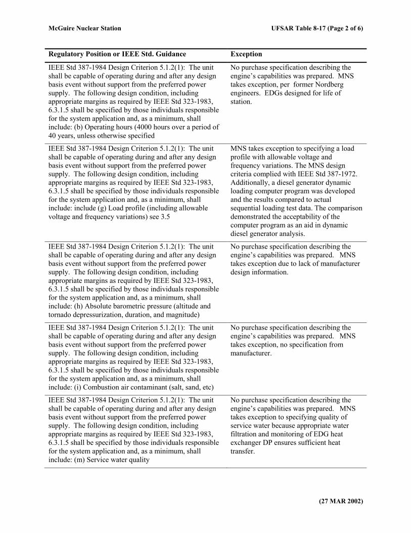
McGuire Nuclear Station UFSAR Table 8-17 (Page 2 of 6)
(27 MAR 2002)
Regulatory Position or IEEE Std. Guidance Exception
IEEE Std 387-1984 Design Criterion 5.1.2(1): The unit
shall be capable of operating during and after any design
basis event without support from the preferred power
supply. The following design condition, including
appropriate margins as required by IEEE Std 323-1983,
6.3.1.5 shall be specified by those individuals responsible
for the system application and, as a minimum, shall
include: (b) Operating hours (4000 hours over a period of
40 years, unless otherwise specified
No purchase specification describing the
engine’s capabilities was prepared. MNS
takes exception, per former Nordberg
engineers. EDGs designed for life of
station.
IEEE Std 387-1984 Design Criterion 5.1.2(1): The unit
shall be capable of operating during and after any design
basis event without support from the preferred power
supply. The following design condition, including
appropriate margins as required by IEEE Std 323-1983,
6.3.1.5 shall be specified by those individuals responsible
for the system application and, as a minimum, shall
include: include (g) Load profile (including allowable
voltage and frequency variations) see 3.5
MNS takes exception to specifying a load
profile with allowable voltage and
frequency variations. The MNS design
criteria complied with IEEE Std 387-1972.
Additionally, a diesel generator dynamic
loading computer program was developed
and the results compared to actual
sequential loading test data. The comparison
demonstrated the acceptability of the
computer program as an aid in dynamic
diesel generator analysis.
IEEE Std 387-1984 Design Criterion 5.1.2(1): The unit
shall be capable of operating during and after any design
basis event without support from the preferred power
supply. The following design condition, including
appropriate margins as required by IEEE Std 323-1983,
6.3.1.5 shall be specified by those individuals responsible
for the system application and, as a minimum, shall
include: (h) Absolute barometric pressure (altitude and
tornado depressurization, duration, and magnitude)
No purchase specification describing the
engine’s capabilities was prepared. MNS
takes exception due to lack of manufacturer
design information.
IEEE Std 387-1984 Design Criterion 5.1.2(1): The unit
shall be capable of operating during and after any design
basis event without support from the preferred power
supply. The following design condition, including
appropriate margins as required by IEEE Std 323-1983,
6.3.1.5 shall be specified by those individuals responsible
for the system application and, as a minimum, shall
include: (i) Combustion air contaminant (salt, sand, etc)
No purchase specification describing the
engine’s capabilities was prepared. MNS
takes exception, no specification from
manufacturer.
IEEE Std 387-1984 Design Criterion 5.1.2(1): The unit
shall be capable of operating during and after any design
basis event without support from the preferred power
supply. The following design condition, including
appropriate margins as required by IEEE Std 323-1983,
6.3.1.5 shall be specified by those individuals responsible
for the system application and, as a minimum, shall
include: (m) Service water quality
No purchase specification describing the
engine’s capabilities was prepared. MNS
takes exception to specifying quality of
service water because appropriate water
filtration and monitoring of EDG heat
exchanger DP ensures sufficient heat
transfer.
McGuire Nuclear Station UFSAR Table 8-17 (Page 3 of 6)
(27 MAR 2002)
Regulatory Position or IEEE Std. Guidance Exception
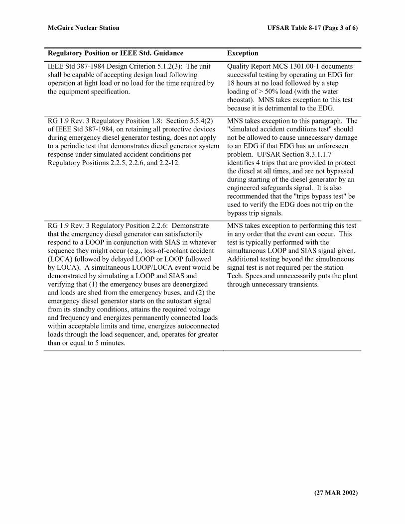
IEEE Std 387-1984 Design Criterion 5.1.2(3): The unit
shall be capable of accepting design load following
operation at light load or no load for the time required by
the equipment specification.
Quality Report MCS 1301.00-1 documents
successful testing by operating an EDG for
18 hours at no load followed by a step
loading of > 50% load (with the water
rheostat). MNS takes exception to this test
because it is detrimental to the EDG.
RG 1.9 Rev. 3 Regulatory Position 1.8: Section 5.5.4(2)
of IEEE Std 387-1984, on retaining all protective devices
during emergency diesel generator testing, does not apply
to a periodic test that demonstrates diesel generator system
response under simulated accident conditions per
Regulatory Positions 2.2.5, 2.2.6, and 2.2-12.
MNS takes exception to this paragraph. The
"simulated accident conditions test" should
not be allowed to cause unnecessary damage
to an EDG if that EDG has an unforeseen
problem. UFSAR Section 8.3.1.1.7
identifies 4 trips that are provided to protect
the diesel at all times, and are not bypassed
during starting of the diesel generator by an
engineered safeguards signal. It is also
recommended that the "trips bypass test" be
used to verify the EDG does not trip on the
bypass trip signals.
RG 1.9 Rev. 3 Regulatory Position 2.2.6: Demonstrate
that the emergency diesel generator can satisfactorily
respond to a LOOP in conjunction with SIAS in whatever
sequence they might occur (e.g., loss-of-coolant accident
(LOCA) followed by delayed LOOP or LOOP followed
by LOCA). A simultaneous LOOP/LOCA event would be
demonstrated by simulating a LOOP and SIAS and
verifying that (1) the emergency buses are deenergized
and loads are shed from the emergency buses, and (2) the
emergency diesel generator starts on the autostart signal
from its standby conditions, attains the required voltage
and frequency and energizes permanently connected loads
within acceptable limits and time, energizes autoconnected
loads through the load sequencer, and, operates for greater
than or equal to 5 minutes.
MNS takes exception to performing this test
in any order that the event can occur. This
test is typically performed with the
simultaneous LOOP and SIAS signal given.
Additional testing beyond the simultaneous
signal test is not required per the station
Tech. Specs.and unnecessarily puts the plant
through unnecessary transients.
McGuire Nuclear Station UFSAR Table 8-17 (Page 4 of 6)
(27 MAR 2002)
Regulatory Position or IEEE Std. Guidance Exception
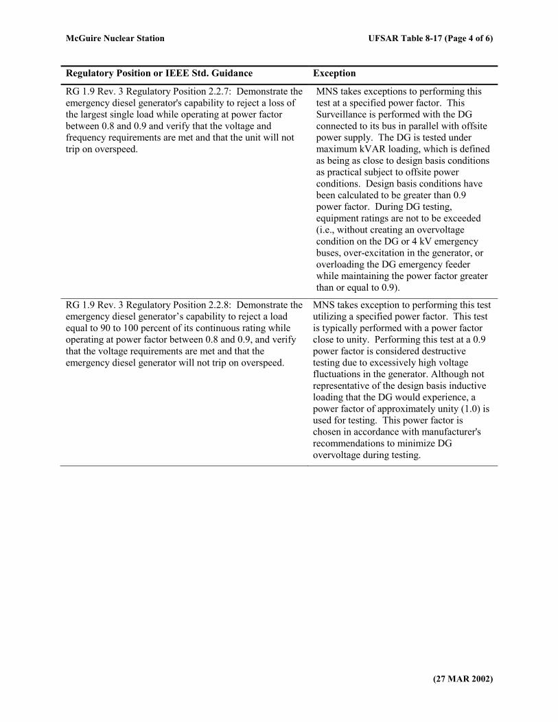
RG 1.9 Rev. 3 Regulatory Position 2.2.7: Demonstrate the
emergency diesel generator's capability to reject a loss of
the largest single load while operating at power factor
between 0.8 and 0.9 and verify that the voltage and
frequency requirements are met and that the unit will not
trip on overspeed.
MNS takes exceptions to performing this
test at a specified power factor. This
Surveillance is performed with the DG
connected to its bus in parallel with offsite
power supply. The DG is tested under
maximum kVAR loading, which is defined
as being as close to design basis conditions
as practical subject to offsite power
conditions. Design basis conditions have
been calculated to be greater than 0.9
power factor. During DG testing,
equipment ratings are not to be exceeded
(i.e., without creating an overvoltage
condition on the DG or 4 kV emergency
buses, over-excitation in the generator, or
overloading the DG emergency feeder
while maintaining the power factor greater
than or equal to 0.9).
RG 1.9 Rev. 3 Regulatory Position 2.2.8: Demonstrate the
emergency diesel generator’s capability to reject a load
equal to 90 to 100 percent of its continuous rating while
operating at power factor between 0.8 and 0.9, and verify
that the voltage requirements are met and that the
emergency diesel generator will not trip on overspeed.
MNS takes exception to performing this test
utilizing a specified power factor. This test
is typically performed with a power factor
close to unity. Performing this test at a 0.9
power factor is considered destructive
testing due to excessively high voltage
fluctuations in the generator. Although not
representative of the design basis inductive
loading that the DG would experience, a
power factor of approximately unity (1.0) is
used for testing. This power factor is
chosen in accordance with manufacturer's
recommendations to minimize DG
overvoltage during testing.
McGuire Nuclear Station UFSAR Table 8-17 (Page 5 of 6)
(27 MAR 2002)
Regulatory Position or IEEE Std. Guidance Exception
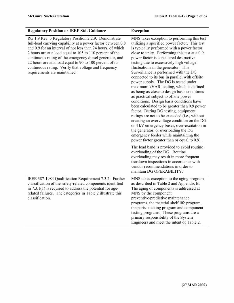
RG 1.9 Rev. 3 Regulatory Position 2.2.9: Demonstrate
full-load carrying capability at a power factor between 0.8
and 0.9 for an interval of not less than 24 hours, of which
2 hours are at a load equal to 105 to 110 percent of the
continuous rating of the emergency diesel generator, and
22 hours are at a load equal to 90 to 100 percent of its
continuous rating. Verify that voltage and frequency
requirements are maintained.
MNS takes exception to performing this test
utilizing a specified power factor. This test
is typically performed with a power factor
close to unity. Performing this test at a 0.9
power factor is considered destructive
testing due to excessively high voltage
fluctuations in the generator. This
Surveillance is performed with the DG
connected to its bus in parallel with offsite
power supply. The DG is tested under
maximum kVAR loading, which is defined
as being as close to design basis conditions
as practical subject to offsite power
conditions. Design basis conditions have
been calculated to be greater than 0.9 power
factor. During DG testing, equipment
ratings are not to be exceeded (i.e., without
creating an overvoltage condition on the DG
or 4 kV emergency buses, over-excitation in
the generator, or overloading the DG
emergency feeder while maintaining the
power factor greater than or equal to 0.9).
The load band is provided to avoid routine
overloading of the DG. Routine
overloading may result in more frequent
teardown inspections in accordance with
vendor recommendations in order to
maintain DG OPERABILITY.
IEEE 387-1984 Qualification Requirement 7.3.2: Further
classification of the safety-related components identified
in 7.3.1(1) is required to address the potential for age-
related failures. The categories in Table 2 illustrate this
classification.
MNS takes exception to the aging program
as described in Table 2 and Appendix B.
The aging of components is addressed at
MNS by the component
preventive/predictive maintenance
programs, the material shelf life program,
the parts stocking program and component
testing programs. These programs are a
primary responsibility of the System
Engineers and meet the intent of Table 2.
McGuire Nuclear Station UFSAR Table 8-17 (Page 6 of 6)
(27 MAR 2002)
Regulatory Position or IEEE Std. Guidance Exception
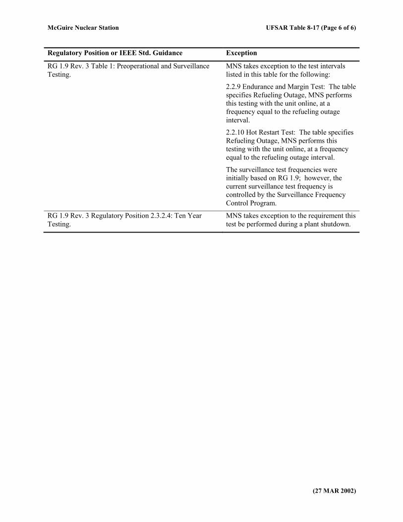
RG 1.9 Rev. 3 Table 1: Preoperational and Surveillance
Testing.
MNS takes exception to the test intervals
listed in this table for the following:
2.2.9 Endurance and Margin Test: The table
specifies Refueling Outage, MNS performs
this testing with the unit online, at a
frequency equal to the refueling outage
interval.
2.2.10 Hot Restart Test: The table specifies
Refueling Outage, MNS performs this
testing with the unit online, at a frequency
equal to the refueling outage interval.
The surveillance test frequencies were
initially based on RG 1.9; however, the
current surveillance test frequency is
controlled by the Surveillance Frequency
Control Program.
RG 1.9 Rev. 3 Regulatory Position 2.3.2.4: Ten Year
Testing.
MNS takes exception to the requirement this
test be performed during a plant shutdown.
McGuire Nuclear Station UFSAR Table 8-18 (Page 1 of 5)
(05 APR 2011)
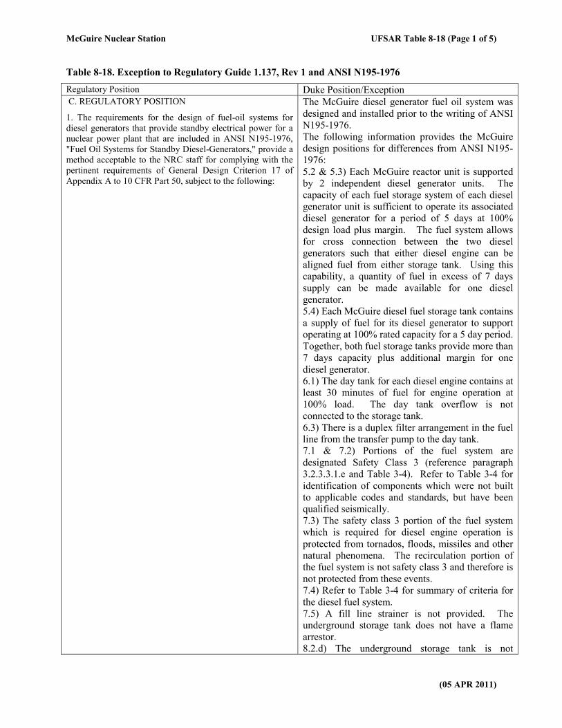
Table 8-18. Exception to Regulatory Guide 1.137, Rev 1 and ANSI N195-1976
Regulatory Position Duke Position/Exception C. REGULATORY POSITION
1. The requirements for the design of fuel-oil systems for
diesel generators that provide standby electrical power for a
nuclear power plant that are included in ANSI N195-1976,
"Fuel Oil Systems for Standby Diesel-Generators," provide a
method acceptable to the NRC staff for complying with the
pertinent requirements of General Design Criterion 17 of
Appendix A to 10 CFR Part 50, subject to the following:
The McGuire diesel generator fuel oil system was
designed and installed prior to the writing of ANSI
N195-1976.
The following information provides the McGuire
design positions for differences from ANSI N195-
1976:
5.2 & 5.3) Each McGuire reactor unit is supported
by 2 independent diesel generator units. The
capacity of each fuel storage system of each diesel
generator unit is sufficient to operate its associated
diesel generator for a period of 5 days at 100%
design load plus margin. The fuel system allows
for cross connection between the two diesel
generators such that either diesel engine can be
aligned fuel from either storage tank. Using this
capability, a quantity of fuel in excess of 7 days
supply can be made available for one diesel
generator.
5.4) Each McGuire diesel fuel storage tank contains
a supply of fuel for its diesel generator to support
operating at 100% rated capacity for a 5 day period.
Together, both fuel storage tanks provide more than
7 days capacity plus additional margin for one
diesel generator.
6.1) The day tank for each diesel engine contains at
least 30 minutes of fuel for engine operation at
100% load. The day tank overflow is not
connected to the storage tank.
6.3) There is a duplex filter arrangement in the fuel
line from the transfer pump to the day tank.
7.1 & 7.2) Portions of the fuel system are
designated Safety Class 3 (reference paragraph
3.2.3.3.1.e and Table 3-4). Refer to Table 3-4 for
identification of components which were not built
to applicable codes and standards, but have been
qualified seismically.
7.3) The safety class 3 portion of the fuel system
which is required for diesel engine operation is
protected from tornados, floods, missiles and other
natural phenomena. The recirculation portion of
the fuel system is not safety class 3 and therefore is
not protected from these events.
7.4) Refer to Table 3-4 for summary of criteria for
the diesel fuel system.
7.5) A fill line strainer is not provided. The
underground storage tank does not have a flame
arrestor.
8.2.d) The underground storage tank is not
McGuire Nuclear Station UFSAR Table 8-18 (Page 2 of 5)
(05 APR 2011)
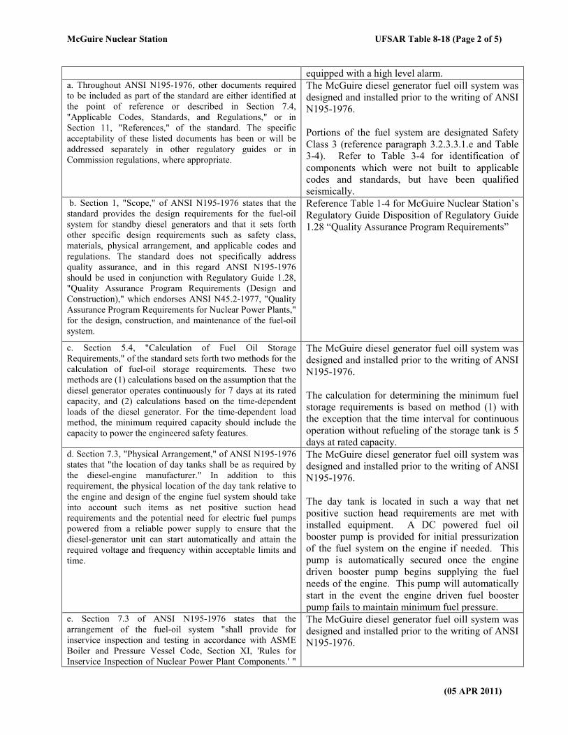
equipped with a high level alarm. a. Throughout ANSI N195-1976, other documents required
to be included as part of the standard are either identified at
the point of reference or described in Section 7.4,
"Applicable Codes, Standards, and Regulations," or in
Section 11, "References," of the standard. The specific
acceptability of these listed documents has been or will be
addressed separately in other regulatory guides or in
Commission regulations, where appropriate.
The McGuire diesel generator fuel oill system was
designed and installed prior to the writing of ANSI
N195-1976.
Portions of the fuel system are designated Safety
Class 3 (reference paragraph 3.2.3.3.1.e and Table
3-4). Refer to Table 3-4 for identification of
components which were not built to applicable
codes and standards, but have been qualified
seismically. b. Section 1, "Scope," of ANSI N195-1976 states that the
standard provides the design requirements for the fuel-oil
system for standby diesel generators and that it sets forth
other specific design requirements such as safety class,
materials, physical arrangement, and applicable codes and
regulations. The standard does not specifically address
quality assurance, and in this regard ANSI N195-1976
should be used in conjunction with Regulatory Guide 1.28,
"Quality Assurance Program Requirements (Design and
Construction)," which endorses ANSI N45.2-1977, "Quality
Assurance Program Requirements for Nuclear Power Plants,"
for the design, construction, and maintenance of the fuel-oil
system.
Reference Table 1-4 for McGuire Nuclear Station’s
Regulatory Guide Disposition of Regulatory Guide
1.28 “Quality Assurance Program Requirements”
c. Section 5.4, "Calculation of Fuel Oil Storage
Requirements," of the standard sets forth two methods for the
calculation of fuel-oil storage requirements. These two
methods are (1) calculations based on the assumption that the
diesel generator operates continuously for 7 days at its rated
capacity, and (2) calculations based on the time-dependent
loads of the diesel generator. For the time-dependent load
method, the minimum required capacity should include the
capacity to power the engineered safety features.
The McGuire diesel generator fuel oill system was
designed and installed prior to the writing of ANSI
N195-1976.
The calculation for determining the minimum fuel
storage requirements is based on method (1) with
the exception that the time interval for continuous
operation without refueling of the storage tank is 5
days at rated capacity. d. Section 7.3, "Physical Arrangement," of ANSI N195-1976
states that "the location of day tanks shall be as required by
the diesel-engine manufacturer." In addition to this
requirement, the physical location of the day tank relative to
the engine and design of the engine fuel system should take
into account such items as net positive suction head
requirements and the potential need for electric fuel pumps
powered from a reliable power supply to ensure that the
diesel-generator unit can start automatically and attain the
required voltage and frequency within acceptable limits and
time.
The McGuire diesel generator fuel oill system was
designed and installed prior to the writing of ANSI
N195-1976.
The day tank is located in such a way that net
positive suction head requirements are met with
installed equipment. A DC powered fuel oil
booster pump is provided for initial pressurization
of the fuel system on the engine if needed. This
pump is automatically secured once the engine
driven booster pump begins supplying the fuel
needs of the engine. This pump will automatically
start in the event the engine driven fuel booster
pump fails to maintain minimum fuel pressure. e. Section 7.3 of ANSI N195-1976 states that the
arrangement of the fuel-oil system "shall provide for
inservice inspection and testing in accordance with ASME
Boiler and Pressure Vessel Code, Section XI, 'Rules for
Inservice Inspection of Nuclear Power Plant Components.' "
The McGuire diesel generator fuel oill system was
designed and installed prior to the writing of ANSI
N195-1976.
McGuire Nuclear Station UFSAR Table 8-18 (Page 3 of 5)
(05 APR 2011)
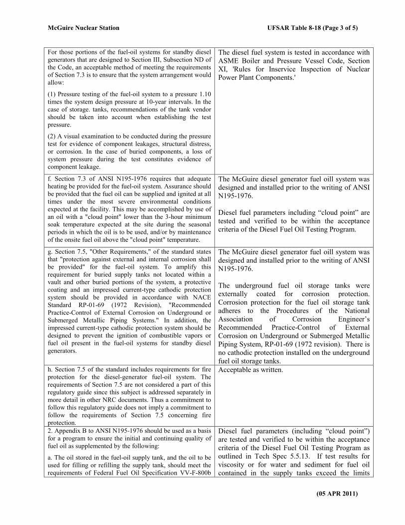
For those portions of the fuel-oil systems for standby diesel
generators that are designed to Section III, Subsection ND of
the Code, an acceptable method of meeting the requirements
of Section 7.3 is to ensure that the system arrangement would
allow:
(1) Pressure testing of the fuel-oil system to a pressure 1.10
times the system design pressure at 10-year intervals. In the
case of storage. tanks, recommendations of the tank vendor
should be taken into account when establishing the test
pressure.
(2) A visual examination to be conducted during the pressure
test for evidence of component leakages, structural distress,
or corrosion. In the case of buried components, a loss of
system pressure during the test constitutes evidence of
component leakage.
The diesel fuel system is tested in accordance with
ASME Boiler and Pressure Vessel Code, Section
XI, 'Rules for Inservice Inspection of Nuclear
Power Plant Components.'
f. Section 7.3 of ANSI N195-1976 requires that adequate
heating be provided for the fuel-oil system. Assurance should
be provided that the fuel oil can be supplied and ignited at all
times under the most severe environmental conditions
expected at the facility. This may be accomplished by use of
an oil with a "cloud point" lower than the 3-hour minimum
soak temperature expected at the site during the seasonal
periods in which the oil is to be used, and/or by maintenance
of the onsite fuel oil above the "cloud point" temperature.
The McGuire diesel generator fuel oill system was
designed and installed prior to the writing of ANSI
N195-1976.
Diesel fuel parameters including “cloud point” are
tested and verified to be within the acceptance
criteria of the Diesel Fuel Oil Testing Program.
g. Section 7.5, "Other Requirements," of the standard states
that "protection against external and internal corrosion shall
be provided" for the fuel-oil system. To amplify this
requirement for buried supply tanks not located within a
vault and other buried portions of the system, a protective
coating and an impressed current-type cathodic protection
system should be provided in accordance with NACE
Standard RP-01-69 (1972 Revision), "Recommended
Practice-Control of External Corrosion on Underground or
Submerged Metallic Piping Systems." In addition, the
impressed current-type cathodic protection system should be
designed to prevent the ignition of combustible vapors or
fuel oil present in the fuel-oil systems for standby diesel
generators.
The McGuire diesel generator fuel oill system was
designed and installed prior to the writing of ANSI
N195-1976.
The underground fuel oil storage tanks were
externally coated for corrosion protection.
Corrosion protection for the fuel oil storage tank
adheres to the Procedures of the National
Association of Corrosion Engineer’s
Recommended Practice-Control of External
Corrosion on Underground or Submerged Metallic
Piping System, RP-01-69 (1972 revision). There is
no cathodic protection installed on the underground
fuel oil storage tanks. h. Section 7.5 of the standard includes requirements for fire
protection for the diesel-generator fuel-oil system. The
requirements of Section 7.5 are not considered a part of this
regulatory guide since this subject is addressed separately in
more detail in other NRC documents. Thus a commitment to
follow this regulatory guide does not imply a commitment to
follow the requirements of Section 7.5 concerning fire
protection.
Acceptable as written.
2. Appendix B to ANSI N195-1976 should be used as a basis
for a program to ensure the initial and continuing quality of
fuel oil as supplemented by the following:
a. The oil stored in the fuel-oil supply tank, and the oil to be
used for filling or refilling the supply tank, should meet the
requirements of Federal Fuel Oil Specification VV-F-800b
Diesel fuel parameters (including “cloud point”)
are tested and verified to be within the acceptance
criteria of the Diesel Fuel Oil Testing Program as
outlined in Tech Spec 5.5.13. If test results for
viscosity or for water and sediment for fuel oil
contained in the supply tanks exceed the limits
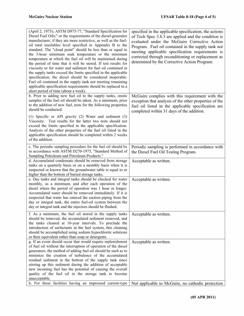
McGuire Nuclear Station UFSAR Table 8-18 (Page 4 of 5)
(05 APR 2011)
(April 2, 1975); ASTM D975-77, "Standard Specification for
Diesel Fuel Oils;" or the requirements of the diesel-generator
manufacturer, if they are more restrictive, as well as the fuel-
oil total insolubles level specified in Appendix B to the
standard. The "cloud point" should be less than or equal to
the 3-hour minimum soak temperature or the minimum
temperature at which the fuel oil will be maintained during
the period of time that it will be stored. If test results for
viscosity or for water and sediment for fuel oil contained in
the supply tanks exceed the limits specified in the applicable
specification, the diesel should be considered inoperable.
Fuel oil contained in the supply tank not meeting remaining
applicable specification requirements should be replaced in a
short period of time (about a week).
specified in the applicable specification, the actions
of Tech Spec 3.8.3 are applied and the condition is
evaluated under the McGuire Corrective Action
Program. Fuel oil contained in the supply tank not
meeting applicable specification requirements is
corrected through reconditioning or replacement as
determined by the Corrective Action Program.
b. Prior to adding new fuel oil to the supply tanks, onsite
samples of the fuel oil should be taken. As a minimum, prior
to the addition of new fuel, tests for the following properties
should be conducted:
(1) Specific or API gravity (2) Water and sediment (3)
Viscosity. Test results for the latter two tests should not
exceed the limits specified in the applicable specification.
Analysis of the other properties of the fuel oil listed in the
applicable specification should be completed within 2 weeks
of the addition.
McGuire complies with this requirement with the
exception that analysis of the other properties of the
fuel oil listed in the applicable specification are
completed within 31 days of the addition.
c. The periodic sampling procedure for the fuel oil should be
in accordance with ASTM D270-1975, "Standard Method of
Sampling Petroleum and Petroleum Products."
Periodic sampling is performed in accordance with
the Diesel Fuel Oil Testing Program.
d. Accumulated condensate should be removed from storage
tanks on a quarterly basis or on a monthly basis when it is
suspected or known that the groundwater table is equal to or
higher than the bottom of buried storage tanks.
Acceptable as written.
e. Day tanks and integral tanks should be checked for water
monthly, as a minimum, and after each operation of the
diesel where the period of operation was 1 hour or longer.
Accumulated water should be removed immediately. If it is
suspected that water has entered the suction piping from the
day or integral tank, the entire fuel-oil system between the
day or integral tank and the injectors should be flushed.
Acceptable as written.
f. As a minimum, the fuel oil stored in the supply tanks
should be removed, the accumulated sediment removed, and
the tanks cleaned at 10-year intervals. To preclude the
introduction of surfactants in the fuel system, this cleaning
should be accomplished using sodium hypochlorite solutions
or their equivalent rather than soap or detergents.
Acceptable as written.
g. If an event should occur that would require replenishment
of fuel oil without the interruption of operation of the diesel
generators, the method of adding fuel oil should be such as to
minimize the creation of turbulence of the accumulated
residual sediment in the bottom of the supply tank since
stirring up this sediment during the addition of acceptable
new incoming fuel has the potential of causing the overall
quality of the fuel oil in the storage tank to become
unacceptable.
Acceptable as written.
h. For those facilities having an impressed current-type Not applicable to McGuire, no cathodic protection
McGuire Nuclear Station UFSAR Table 8-18 (Page 5 of 5)
(05 APR 2011)
cathodic protection system, cathodic protection surveillance
should be conducted according to the following procedures:
(1) At intervals not exceeding 12 months, tests should be
conducted on each underground cathodic protection system
to determine whether the protection is adequate.
(2) The test leads required for cathodic protection should be
maintained in such a condition that electrical measurements
can be obtained to ensure the system is adequately protected.
(3) At intervals not exceeding 2 months, each of the cathodic
protection rectifiers should be inspected.
(4) Records of each inspection and test should be maintained
over the life of the facility to assist in evaluating the extent of
degradation of the corrosion protection systems.
exists on the underground tanks.
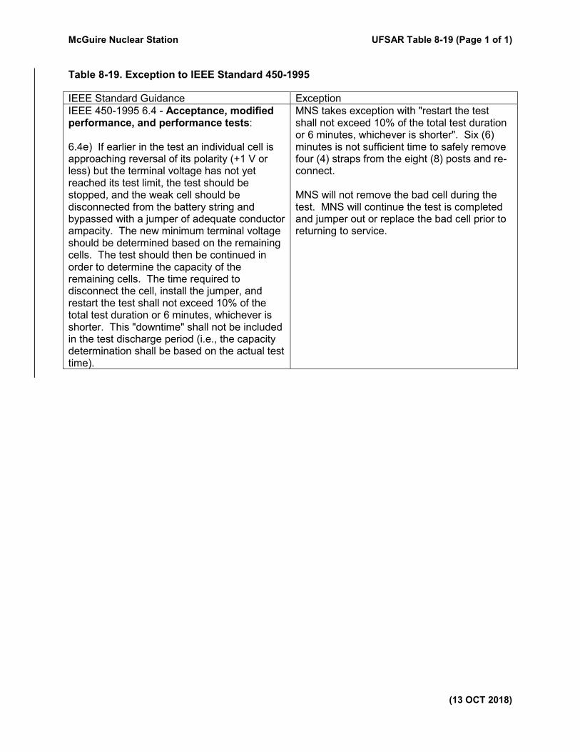
McGuire Nuclear Station UFSAR Table 8-19 (Page 1 of 1)
(13 OCT 2018)
Table 8-19. Exception to IEEE Standard 450-1995
IEEE Standard Guidance Exception
IEEE 450-1995 6.4 - Acceptance, modified performance, and performance tests: 6.4e) If earlier in the test an individual cell is approaching reversal of its polarity (+1 V or less) but the terminal voltage has not yet reached its test limit, the test should be stopped, and the weak cell should be disconnected from the battery string and bypassed with a jumper of adequate conductor ampacity. The new minimum terminal voltage should be determined based on the remaining cells. The test should then be continued in order to determine the capacity of the remaining cells. The time required to disconnect the cell, install the jumper, and restart the test shall not exceed 10% of the total test duration or 6 minutes, whichever is shorter. This "downtime" shall not be included in the test discharge period (i.e., the capacity determination shall be based on the actual test time).
MNS takes exception with "restart the test shall not exceed 10% of the total test duration or 6 minutes, whichever is shorter". Six (6) minutes is not sufficient time to safely remove four (4) straps from the eight (8) posts and re-connect. MNS will not remove the bad cell during the test. MNS will continue the test is completed and jumper out or replace the bad cell prior to returning to service.