mcosmos-e4180-525
DESCRIPTION
Mcoscosmos Mitutiyo manualTRANSCRIPT
�����������������������������������������
������������������������������
�����������������������������
�����������������������������
��������������
�����������������
����������������
������������������������
Catalog No. E4180-525
Coordinate Measuring Machines
High-specification user-friendly software for CMM
Data Processing System for Manual/CNC CMM
MCOSMOS
2
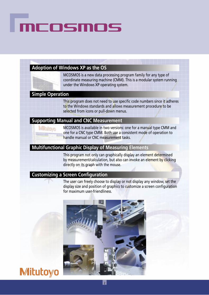
MCOSMOS is a new data processing program family for any type of coordinate measuring machine (CMM). This is a modular system running under the Windows XP operating system.
Adoption of Windows XP as the OS
This program does not need to use specific code numbers since it adheres to the Windows standards and allows measurement procedure to be selected from icons or pull-down menus.
Simple Operation
MCOSMOS is available in two versions: one for a manual type CMM and one for a CNC type CMM. Both use a consistent mode of operation to handle manual or CNC measurement tasks.
Supporting Manual and CNC Measurement
This program not only can graphically display an element determined by measurement/calculation, but also can invoke an element by clicking directly on its graph with the mouse.
Multifunctional Graphic Display of Measuring Elements
The user can freely choose to display or not display any window, set the display size and position of graphics to customize a screen configuration for maximum user-friendliness.
Customizing a Screen Configuration

3
System performance from every viewpoint
PartManager The control center from which the software package is initialized, and individual part programs are managed.
Performance features of standard software packages.
MCOSMOS 1 MCOSMOS 2 MCOSMOS 3
GEOPAK (Geometry module)For (online/offline) part program creation, using the measurement of geometric elements. Extensive tolerance comparisons and output functions are included.
CAT1000S (3D freeform surface evaluation module)CAD model based generation of surface measurement points, and comparison of actual/nominal data, with graphical output.
CAT1000P (CAD based programming module)For (online/offline) part program creation, using the measurement of geometric elements directly from the CAD model, with automatic collision avoidance.
SCANPAK (2D profile evaluation module)For the scanning and evaluation of workpiece contours, and 3D digitizing of surfaces.
Manual CNC
* CAT 1000S and SCANPAK can be individually added to MCOSMO 1 and MCOSMOS 2.
4
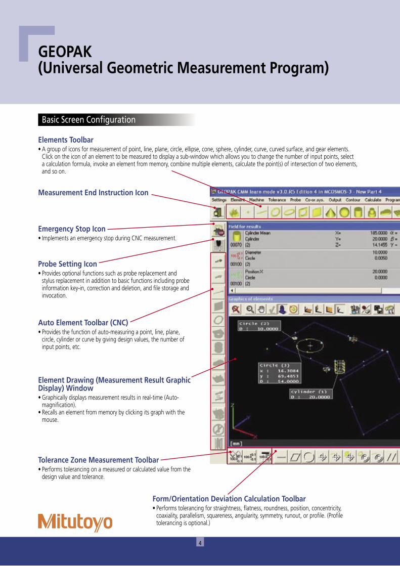
GEOPAK (Universal Geometric Measurement Program)
Elements Toolbar• A group of icons for measurement of point, line, plane, circle, ellipse, cone, sphere, cylinder, curve, curved surface, and gear elements.
Click on the icon of an element to be measured to display a sub-window which allows you to change the number of input points, select a calculation formula, invoke an element from memory, combine multiple elements, calculate the point(s) of intersection of two elements, and so on.
Measurement End Instruction Icon
Emergency Stop Icon• Implements an emergency stop during CNC measurement.
Probe Setting Icon• Provides optional functions such as probe replacement and
stylus replacement in addition to basic functions including probe information key-in, correction and deletion, and file storage and invocation.
Auto Element Toolbar (CNC)• Provides the function of auto-measuring a point, line, plane,
circle, cylinder or curve by giving design values, the number of input points, etc.
Element Drawing (Measurement Result Graphic Display) Window• Graphically displays measurement results in real-time (Auto-
magnification).• Recalls an element from memory by clicking its graph with the
mouse.
Tolerance Zone Measurement Toolbar• Performs tolerancing on a measured or calculated value from the
design value and tolerance.
Form/Orientation Deviation Calculation Toolbar• Performs tolerancing for straightness, flatness, roundness, position, concentricity,
coaxiality, parallelism, squareness, angularity, symmetry, runout, or profile. (Profile tolerancing is optional.)
Basic Screen Configuration
5
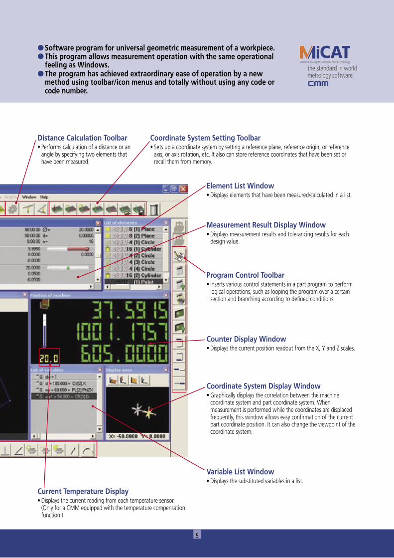
● Software program for universal geometric measurement of a workpiece.● This program allows measurement operation with the same operational
feeling as Windows.● The program has achieved extraordinary ease of operation by a new
method using toolbar/icon menus and totally without using any code or code number.
Current Temperature Display• Displays the current reading from each temperature sensor.
(Only for a CMM equipped with the temperature compensation function.)
Distance Calculation Toolbar• Performs calculation of a distance or an
angle by specifying two elements that have been measured.
Coordinate System Setting Toolbar• Sets up a coordinate system by setting a reference plane, reference origin, or reference
axis, or axis rotation, etc. It also can store reference coordinates that have been set or recall them from memory.
Element List Window• Displays elements that have been measured/calculated in a list.
Program Control Toolbar• Inserts various control statements in a part program to perform
logical operations, such as looping the program over a certain section and branching according to defined conditions.
Measurement Result Display Window• Displays measurement results and tolerancing results for each
design value.
Counter Display Window• Displays the current position readout from the X, Y and Z scales.
Coordinate System Display Window• Graphically displays the correlation between the machine
coordinate system and part coordinate system. When measurement is performed while the coordinates are displaced frequently, this window allows easy confirmation of the current part coordinate position. It can also change the viewpoint of the coordinate system.
Variable List Window• Displays the substituted variables in a list.
6
PART MANAGER
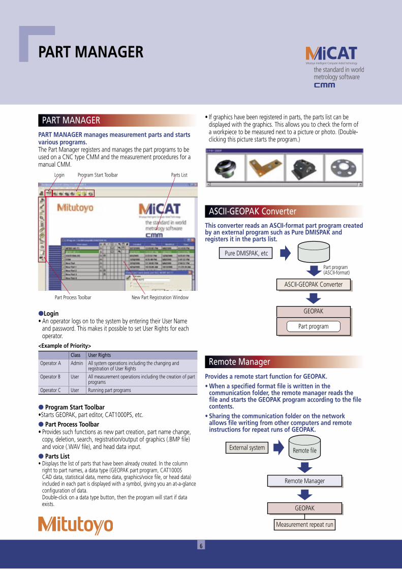
PART MANAGER manages measurement parts and starts various programs.The Part Manager registers and manages the part programs to be used on a CNC type CMM and the measurement procedures for a manual CMM.
●Login• An operator logs on to the system by entering their User Name
and password. This makes it possible to set User Rights for each operator.
● Program Start Toolbar•Starts GEOPAK, part editor, CAT1000PS, etc.● Part Process Toolbar• Provides such functions as new part creation, part name change,
copy, deletion, search, registration/output of graphics (.BMP file) and voice (.WAV file), and head data input.
● Parts List• Displays the list of parts that have been already created. In the column
right to part names, a data type (GEOPAK part program, CAT1000S CAD data, statistical data, memo data, graphics/voice file, or head data) included in each part is displayed with a symbol, giving you an at-a-glance configuration of data.
Double-click on a data type button, then the program will start if data exists.
This converter reads an ASCII-format part program created by an external program such as Pure DMISPAK and registers it in the parts list.
Provides a remote start function for GEOPAK.• When a specified format file is written in the
communication folder, the remote manager reads the file and starts the GEOPAK program according to the file contents.
• Sharing the communication folder on the network allows file writing from other computers and remote instructions for repeat runs of GEOPAK.
�����������������
����������������������
���������������������������
������
������������
��������������
������
����������������������
��������������� ����������
<Example of Priority>
Class User Rights
Operator A Admin All system operations including the changing and registration of User Rights
Operator B User All measurement operations including the creation of part programs
Operator C User Running part programs
PART MANAGER
Remote Manager
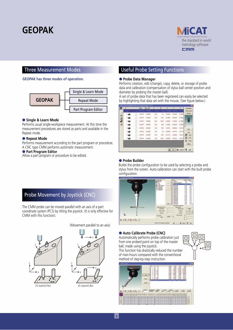
• If graphics have been registered in parts, the parts list can be displayed with the graphics. This allows you to check the form of a workpiece to be measured next to a picture or photo. (Double-clicking this picture starts the program.)
ASCII-GEOPAK Converter
New Part Registration Window
Login Program Start Toolbar Parts List
Part Process Toolbar
7
GEOPAK has three modes of operation.
● Single & Learn ModePerforms usual single-workpiece measurement. At this time the measurement procedures are stored as parts and available in the Repeat mode.● Repeat ModePerforms measurement according to the part program or procedure. A CNC type CMM performs automatic measurement.● Part Program EditorAllow a part program or procedure to be edited.
������ �����������
�������������������
�������������������
�
�
���
�
�
�
� �
�
��
�
������������������������������
������������������������������������
�
�
�
�
The CMM probe can be moved parallel with an axis of a part coordinate system (PCS) by tilting the joystick. (It is only effective for CMM with this function).
GEOPAK
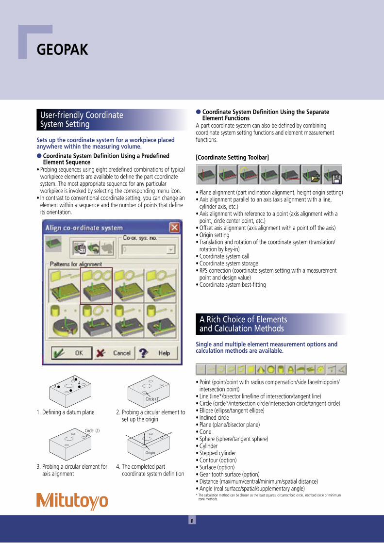
● Probe Data ManagerPerforms creation, edit (change), copy, delete, or storage of probe data and calibration (compensation of stylus ball center position and diameter by probing the master ball).A set of probe data that has been registered can easily be selected by highlighting that data set with the mouse. (See figure below.)
Three Measurement Modes
● Probe BuilderBuilds the probe configuration to be used by selecting a probe and stylus from the screen. Auto-calibration can start with the built probe configuration.
● Auto Calibrate Probe (CNC)Automatically performs probe calibration just from one probed point on top of the master ball, made using the joystick.This function has drastically reduced the number of man-hours compared with the conventional method of step-by-step instruction.
Useful Probe Setting Functions
Probe Movement by Joystick (CNC)
8
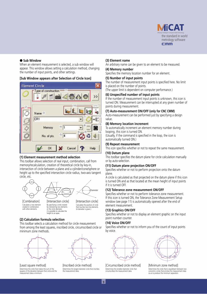
Sets up the coordinate system for a workpiece placed anywhere within the measuring volume.● Coordinate System Definition Using a Predefined
Element Sequence• Probing sequences using eight predefined combinations of typical
workpiece elements are available to define the part coordinate system. The most appropriate sequence for any particular workpiece is invoked by selecting the corresponding menu icon.
• In contrast to conventional coordinate setting, you can change an element within a sequence and the number of points that define its orientation.
��
��
����������
������
�����������
● Coordinate System Definition Using the Separate Element Functions
A part coordinate system can also be defined by combining coordinate system setting functions and element measurement functions.
[Coordinate Setting Toolbar]
• Plane alignment (part inclination alignment, height origin setting)• Axis alignment parallel to an axis (axis alignment with a line,
cylinder axis, etc.)• Axis alignment with reference to a point (axis alignment with a
point, circle center point, etc.)• Offset axis alignment (axis alignment with a point off the axis)• Origin setting• Translation and rotation of the coordinate system (translation/
rotation by key-in)• Coordinate system call• Coordinate system storage• RPS correction (coordinate system setting with a measurement
point and design value)• Coordinate system best-fitting
Single and multiple element measurement options and calculation methods are available.
• Point (point/point with radius compensation/side face/midpoint/intersection point)
• Line (line*/bisector line/line of intersection/tangent line)• Circle (circle*/intersection circle/intersection circle/tangent circle)• Ellipse (ellipse/tangent ellipse)• Inclined circle• Plane (plane/bisector plane)• Cone• Sphere (sphere/tangent sphere)• Cylinder• Stepped cylinder• Contour (option)• Surface (option)• Gear tooth surface (option)• Distance (maximum/central/minimum/spatial distance)• Angle (real surface/spatial/supplementary angle)* The calculation method can be chosen as the least squares, circumscribed circle, inscribed circle or minimum
zone methods.
GEOPAK
A Rich Choice of Elements and Calculation Methods
User-friendly Coordinate System Setting
1. Defining a datum plane 2. Probing a circular element to set up the origin
3. Probing a circular element for axis alignment
4. The completed part coordinate system definition
9
● Sub WindowWhen an element measurement is selected, a sub window will appear. This window allows setting a calculation method, changing the number of input points, and other settings.
[Sub Window appears after Selection of Circle Icon]
(1) Element measurement method selectionThis toolbar allows selection of real input, combination, call from memory/recalculation, creation of theoretical circle by key-in, intersection of circle between a plane and a cylinder/cone/sphere or height up to the specified intersection circle radius, two-axis tangent circle, etc.
��
�
�
���������������������
��������
������������������������������������������������������������������������������������������������������
��������������������������������������������������������������������������������������������������������������������������������������
����������������������������������������������������������������������������������������
(2) Calculation formula selectionThis toolbar selects a calculation method for circle measurement from among the least squares, inscribed circle, circumscribed circle or minimum zone methods.
[Least square method]Determines the circle that makes the sum of the squares of the deviation between that circle and the measurement data a minimum.
[Inscribed circle method]Determines the largest diameter circle that inscribes the measurement data.
[Circumscribed circle method]Determines the smallest diameter circle that circumscribes the measurement data.
[Minimum zone method]Determines the circle that is equidistant between two concentric circles that enclose the measurement data so as to produce the minimum separation.
(3) Element nameAn arbitrary name can be given to an element to be measured.(4) Memory numberSpecifies the memory location number for an element.(5) Number of input pointsThe number of measurement input points is specified here. No limit is placed on the number of points.(The upper limit is dependent on computer performance.)(6) Unspecified number of input pointsIf the number of measurement input points is unknown, this icon is turned ON. Measurement can be interrupted at any given number of points during measurement.(7) Auto-measurement ON/OFF (only for CNC CMM)Auto-measurement can be performed just by specifying a design value.(8) Memory location incrementTo automatically increment an element memory number during looping, this icon is turned ON. (Usually, if the command is specified in the loop, the icon is automatically turned ON.)(9) Repeat measurementThis icon specifies whether or not to repeat the same measurement.(10) Datum planeThis toolbar specifies the datum plane for circle calculation manually or by auto-selection.(11) Datum plane projection ON/OFFSpecifies whether or not to perform projection onto the datum plane.A circle is calculated as that projected on the datum plane if this icon is turned ON and as that located at the mean height of input points if it is turned OFF.(12) Tolerance zone measurement ON/OFFSpecifies whether or not to perform tolerance zone measurement.If this icon is turned ON, the Tolerance Zone Measurement Setup window (see page 11) is automatically opened after the end of element measurement.(13) Graphics ON/OFFSpecifies whether or not to display an element graphic on the input point number counter.(14) Voice ON/OFFSpecifies whether or not to inform you of the count of input points by voice.
(1)
(2)
(3)
(10)
(7)
(8)
(9)(6)
(4)
(5)
(11)
(12)
(13)
(14)
10
Compares element data from measurement or calculation against the design value for a specified tolerance.● Element/Form Tolerance Zone MeasurementThe measurement result for an element is analyzed by specifying the element that has been measured or calculated and giving the design value and tolerance to be applied.
[Items That Can Be Toleranced for Each Element]
Elements Items to be specifiedPoint CoordinateLine Coordinate, angle, straightnessPlane Coordinate, angle, distance, flatnessCircle Coordinate, radius/diameter, roundnessEllipse Coordinate, minor axis, major axis, ellipticityCone Coordinate, angle, full apex angle/half apex angle, conicitySphere Coordinate, radius, diameter, roundness, sphericityCylinder Coordinate, radius, diameter, cylindricityDistance Distance and its individual X, Y, Z component outputsAngle Spatial angle, XY-, YZ-, and ZX-projected angles
GEOPAK
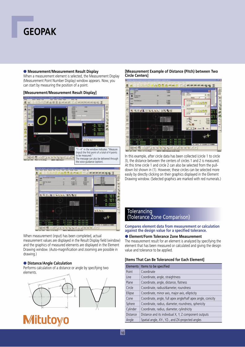
● Measurement/Measurement Result DisplayWhen a measurement element is selected, the Measurement Display (Measurement Point Number Display) window appears. Now, you can start by measuring the position of a point.
[Measurement/Measurement Result Display]
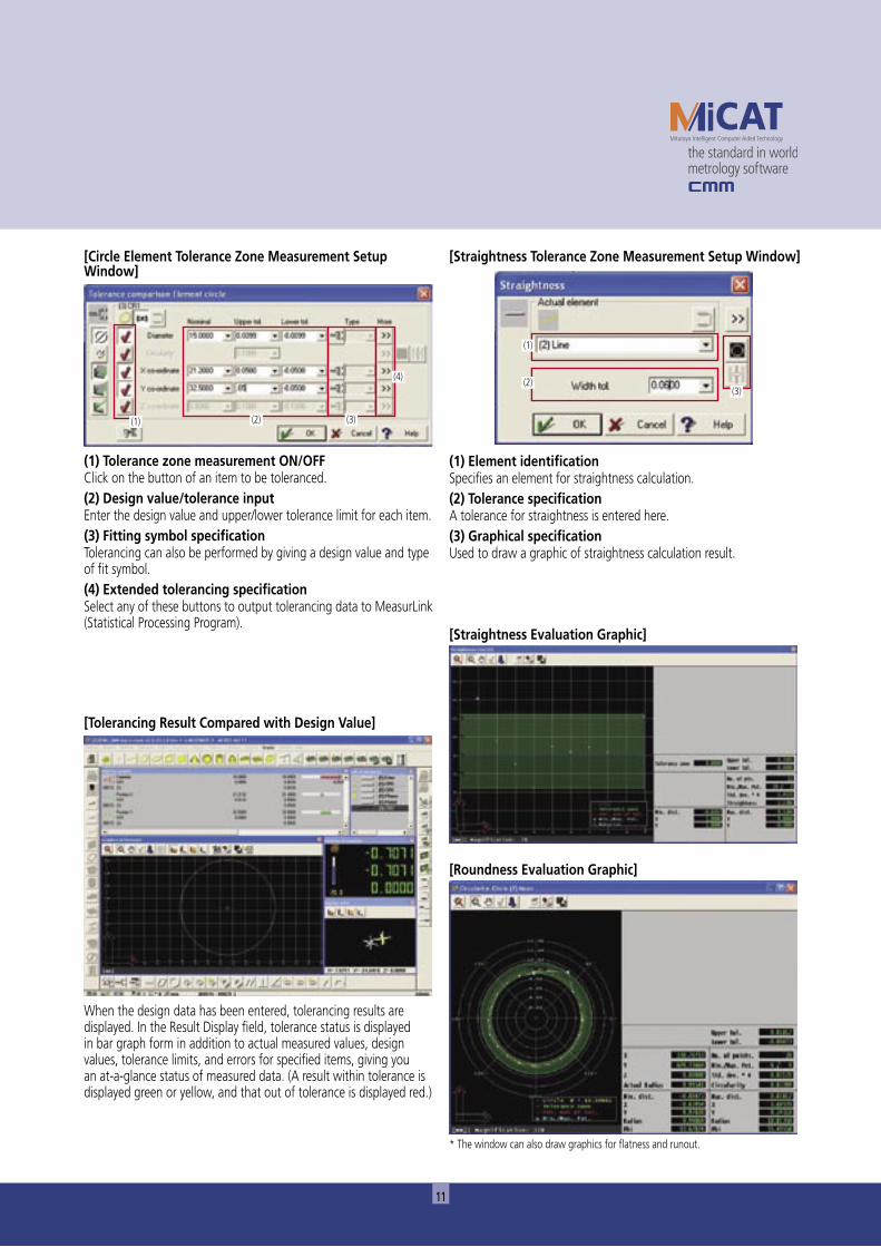
● Distance/Angle CalculationPerforms calculation of a distance or angle by specifying two elements.
[Measurement Example of Distance (Pitch) between Two Circle Centers]
In this example, after circle data has been collected (circle 1 to circle 3), the distance between the centers of circles 1 and 2 is measured. At this time circle 1 and circle 2 can also be selected from the pull-down list shown in (1). However, these circles can be selected more easily by directly clicking on their graphics displayed in the Element Drawing window. (Selected graphics are marked with red numerals.)
When measurement (input) has been completed, actual measurement values are displayed in the Result Display field (window) and the graphics of measured elements are displayed in the Element Drawing window. (Auto-magnification and zooming are possible in drawing.)
Tolerancing (Tolerance Zone Comparison)
“1 - 4” in the window indicates “Measure (input) the first point of a total of 4 points to be measured.”The message can also be delivered through the voice guidance (option).
(1)
11
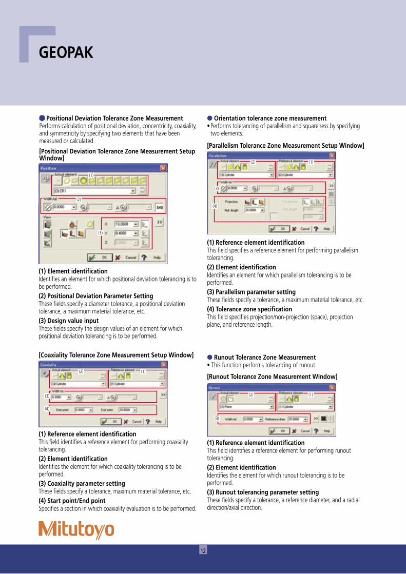
(1) Tolerance zone measurement ON/OFFClick on the button of an item to be toleranced.(2) Design value/tolerance inputEnter the design value and upper/lower tolerance limit for each item.(3) Fitting symbol specificationTolerancing can also be performed by giving a design value and type of fit symbol.(4) Extended tolerancing specificationSelect any of these buttons to output tolerancing data to MeasurLink (Statistical Processing Program).
When the design data has been entered, tolerancing results are displayed. In the Result Display field, tolerance status is displayed in bar graph form in addition to actual measured values, design values, tolerance limits, and errors for specified items, giving you an at-a-glance status of measured data. (A result within tolerance is displayed green or yellow, and that out of tolerance is displayed red.)
[Tolerancing Result Compared with Design Value]
(1) Element identificationSpecifies an element for straightness calculation.(2) Tolerance specificationA tolerance for straightness is entered here.(3) Graphical specificationUsed to draw a graphic of straightness calculation result.
* The window can also draw graphics for flatness and runout.
[Straightness Tolerance Zone Measurement Setup Window]
[Straightness Evaluation Graphic]
[Roundness Evaluation Graphic]
[Circle Element Tolerance Zone Measurement Setup Window]
(1) (2) (3)
(4)
(1)
(2)(3)
12
GEOPAK
(1) Reference element identificationThis field specifies a reference element for performing parallelism tolerancing.(2) Element identificationIdentifies an element for which parallelism tolerancing is to be performed.(3) Parallelism parameter settingThese fields specify a tolerance, a maximum material tolerance, etc.(4) Tolerance zone specificationThis field specifies projection/non-projection (space), projection plane, and reference length.
● Runout Tolerance Zone Measurement• This function performs tolerancing of runout.
(1) Reference element identificationThis field identifies a reference element for performing runout tolerancing.(2) Element identificationIdentifies the element for which runout tolerancing is to be performed.(3) Runout tolerancing parameter settingThese fields specify a tolerance, a reference diameter, and a radial direction/axial direction.
[Runout Tolerance Zone Measurement Window]
[Coaxiality Tolerance Zone Measurement Setup Window]
(1) Reference element identificationThis field identifies a reference element for performing coaxiality tolerancing.(2) Element identificationIdentifies the element for which coaxiality tolerancing is to be performed.(3) Coaxiality parameter settingThese fields specify a tolerance, maximum material tolerance, etc.(4) Start point/End pointSpecifies a section in which coaxiality evaluation is to be performed.
● Orientation tolerance zone measurement• Performs tolerancing of parallelism and squareness by specifying
two elements.
[Parallelism Tolerance Zone Measurement Setup Window]
● Positional Deviation Tolerance Zone MeasurementPerforms calculation of positional deviation, concentricity, coaxiality, and symmetricity by specifying two elements that have been measured or calculated.
(1) Element identificationIdentifies an element for which positional deviation tolerancing is to be performed.(2) Positional Deviation Parameter SettingThese fields specify a diameter tolerance, a positional deviation tolerance, a maximum material tolerance, etc.(3) Design value inputThese fields specify the design values of an element for which positional deviation tolerancing is to be performed.
[Positional Deviation Tolerance Zone Measurement Setup Window]
(2) (1)
(3)
(4)
(1)
(2)
(2)
(3)
(1)
(3)
(4)
(2) (1)
(3)
13
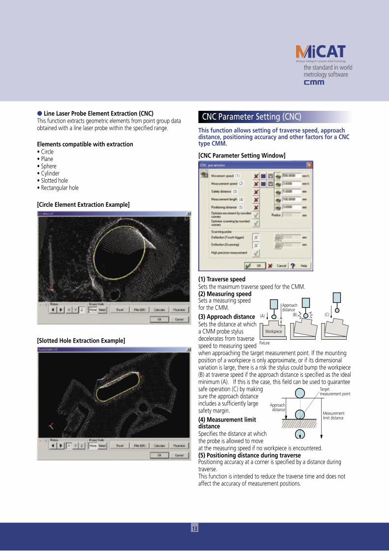
This function allows setting of traverse speed, approach distance, positioning accuracy and other factors for a CNC type CMM.
[CNC Parameter Setting Window]
(1) Traverse speedSets the maximum traverse speed for the CMM.(2) Measuring speedSets a measuring speed for the CMM.(3) Approach distanceSets the distance at which a CMM probe stylus decelerates from traverse speed to measuring speed when approaching the target measurement point. If the mounting position of a workpiece is only approximate, or if its dimensional variation is large, there is a risk the stylus could bump the workpiece (B) at traverse speed if the approach distance is specified as the ideal minimum (A). If this is the case, this field can be used to guarantee safe operation (C) by making sure the approach distance includes a sufficiently large safety margin.(4) Measurement limit distanceSpecifies the distance at which the probe is allowed to move at the measuring speed if no workpiece is encountered.(5) Positioning distance during traversePositioning accuracy at a corner is specified by a distance during traverse.This function is intended to reduce the traverse time and does not affect the accuracy of measurement positions.
����������������
������������������������
��������������������������
����������������
���������
�������
��� ��� ���
[Circle Element Extraction Example]
● Line Laser Probe Element Extraction (CNC)This function extracts geometric elements from point group data obtained with a line laser probe within the specified range.
Elements compatible with extraction• Circle• Plane• Sphere• Cylinder• Slotted hole• Rectangular hole
[Slotted Hole Extraction Example]
CNC Parameter Setting (CNC)
(1)
(2)
(3)
(4)
(5)
14
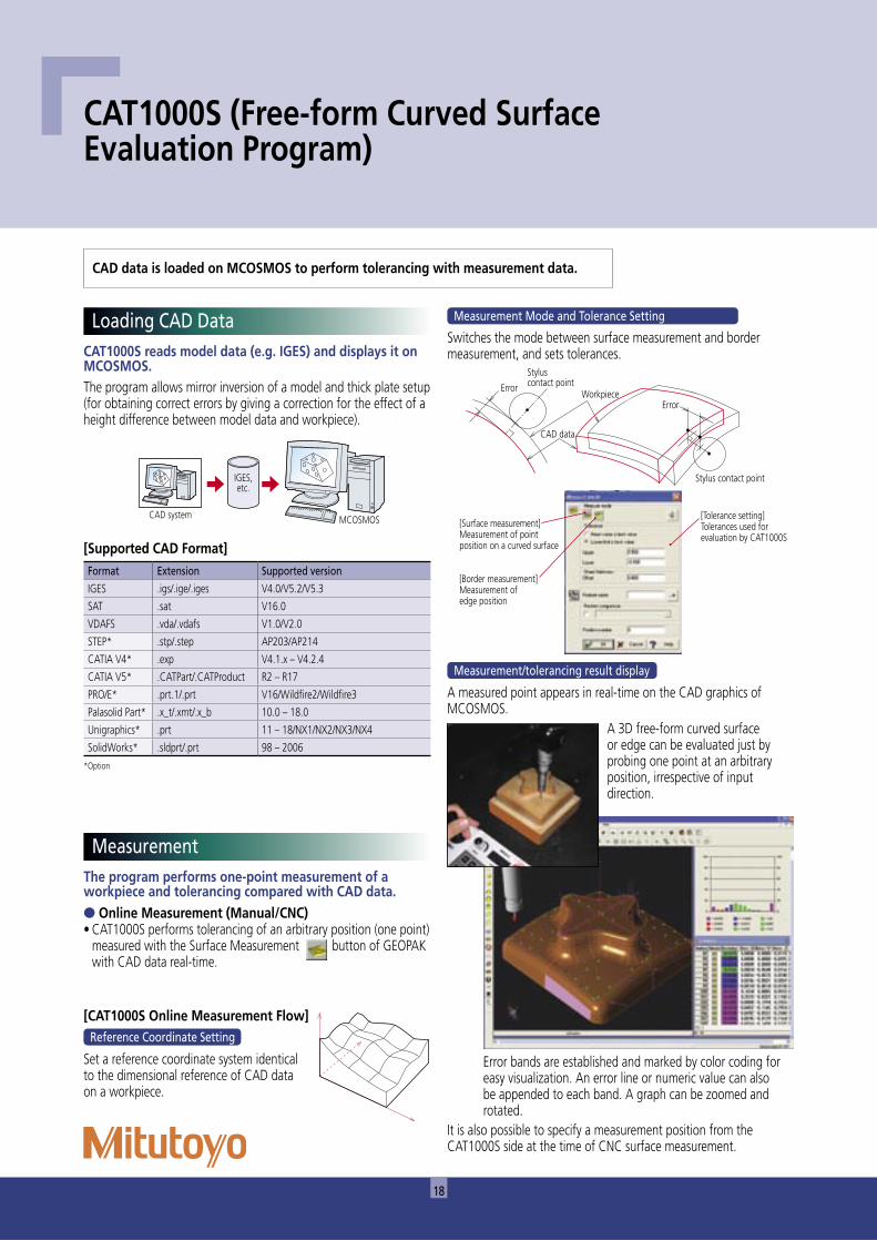
[Auto Circle Measurement Setup Window]
(1) Inside/outside diameterSpecifies the inside or outside diameter of a circle to be automatically measured.(2) Number of points for auto circle measurementSpecifies the number of points with which a circle is automatically measured.(3) Circle diameterSpecifies the diameter of a circle to be automatically measured.(4) Drive plane switchIdentifies the plane on which a circle is positioned.(5) Circle center coordinatesSpecifies the center coordinates of a circle to be automatically measured. Cartesian, cylindrical or spherical coordinates can be used.(6) Partial circle auto-measurementEnables auto-measurement of a partial circle by specifying the start angle and end angle.
������������������������������������������������������������������������
���������������������������������������������������������������������������������������
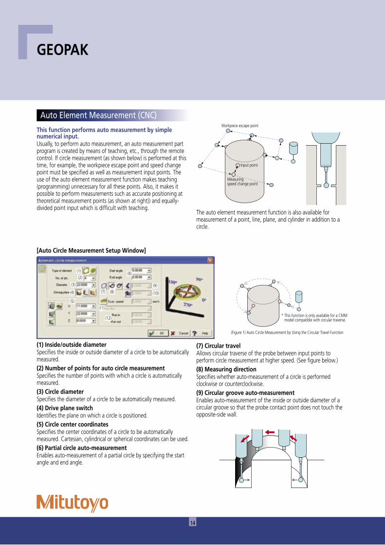
This function performs auto measurement by simple numerical input.Usually, to perform auto measurement, an auto measurement part program is created by means of teaching, etc., through the remote control. If circle measurement (as shown below) is performed at this time, for example, the workpiece escape point and speed change point must be specified as well as measurement input points. The use of the auto element measurement function makes teaching (programming) unnecessary for all these points. Also, it makes it possible to perform measurements such as accurate positioning at theoretical measurement points (as shown at right)) and equally-divided point input which is difficult with teaching.
����������������������������
�����������
����������������������
The auto element measurement function is also available for measurement of a point, line, plane, and cylinder in addition to a circle.
GEOPAK
(7) Circular travelAllows circular traverse of the probe between input points to perform circle measurement at higher speed. (See figure below.)(8) Measuring directionSpecifies whether auto-measurement of a circle is performed clockwise or counterclockwise.(9) Circular groove auto-measurementEnables auto-measurement of the inside or outside diameter of a circular groove so that the probe contact point does not touch the opposite-side wall.
Auto Element Measurement (CNC)
(1)
(2)
(3)
(4)
(5)
(6)
(7) (8)(9)
(10)
(11)
(12)

15
This mode implements measuring procedures based on existing part programs.
(1) Part specificationThis field specifies the part program and the number of times this program is to run.(2) Offset valuesUsed when a number of workpieces are to be measured with one instruction. The workpieces are arranged in a regular 2-D rectangular grid pattern in the XY, YZ or XZ planes at a specified pitch in each direction.
(1) Clearance height ON/OFF(2) Travel axis selection(3) Clearance height Z coordinate
����������������
�����������������
(3) Thermal expansion coefficient (effective only for a CMM equipped with the temperature compensation function)
The thermal expansion coefficient of a workpiece is specified in this field so that the CMM can convert a measurement result obtained at a temperature other than 20°C to that at 20°C.
[Clearance Height]The probe contact point can be made to return automatically to a specified height above the table after a measurement.It is thereby possible to create more simplified part programs by omitting the input of traverse instructions conventionally specified one by one.
�����������������������������������������������������������������������������������������������
���
(10) Direct measurement of a tapped holeIf the position of a tapped hole is measured as if it were a plain hole then a large measurement error will usually occur. The conventional way of accurately measuring tapped hole position is to screw a tooling ball into the hole so that the ball can be probed instead. This function offers the faster alternative of probing the thread directly by driving the contact point in a spiral that matches the diameter and pitch. (Registered patent)
� � �
��
�
��
(11) Contour measurement by design value scanning (scanning probe function)
Performs design value scanning at a specified scanning speed. The function enables filter processing at the same time.(12) Start-up/post-travel angle specificationSpecifies a start-up angle and post-travel angle for contour measurement by design value scanning.
Repeat Mode
(3)
(2)
(1)
(1)(2) (3)

16
It is possible to create a part program that can be changed according to the measurement situation by inserting various control statements.
For example, the following operations can be executed with these control statements.• If the measurement result of a certain feature is decided as NG, the
part is measured three times. (Otherwise, the program is stopped.)
• As shown in the right figure, the workpieces, which are different only in position between holes A and B depending on pin height H on the top, are to be measured with one part program.
• A measurement result is to be substituted in a particular computing equation.
�
��
GEOPAK
This function allows editing of a part program.MCOSMOS part programs have a more easily understandable configuration compared with the conventional program since they are given the same icon and element name as the measurement and detailed information can also be included.
[Part Program List]
�������������������������
To edit a part program, highlight the line to be corrected (or inserted) and then execute the correction command. The following sub window identical to measurement will appear. Now a correction can be made to a numeric value, etc.
[Part Program Correction Example]
#131G14 X5,Y5,Z0;CL0,CM0,CN-1G14 X125,Y5,Z0;CL0,CM0,CN-1G14 X60,Y110,Z0;CL0,CM0,CN-1#523R#141.4G41 X15,Y18,Z-5;;D10;;H10;N4#531R#141.4G41 X110,Y0,Z-5;;D20;;H10:N4
Program ControlPart Program Editor
Control statement Control information
Loop•Repeats a specified series of instructions for a fixed number of times.
Related icons: Loop initiation, Loop termination
Branch
•Departs from the normal sequence of executing instruction according
to the given condition.
Related icons: Branch If, Branch initiation,
Branch termination, Else
Goto
•Transfers execution from the normal sequence control to a predefined
label.
Related icons: Goto, Label definition
Sub-program
•Returns to the original program after executing a specified
subprogram.
Related icons: Subprogram initiation, Subprogram termination
Variable/calculation
•Defines a variable or a calculation formula.
Related icons: Variable definition and calculation, others

17
This function allows display of graphics (.bmp/.jpg file) that have been created beforehand in the following window. The use of this window (as shown below) will be an operating procedure guide for beginners who are unfamiliar with the operating instructions.This window also allows comment display or voice output (.WAV file).
Result data is output to a printer or a file.● Output to PrinterThe program provides highly-flexible printouts by specifying data items such as header, footer, comment (text), all data, out-of-tolerance data only, control limit data only, etc.
At the time of tolerance zone measurement a result
marking is appended to each measurement value so that any trend may be
seen easily.
����������� ������������
�����������������
�����������
● Output to File• The information to be displayed in the Result Display field can be
stored in a specified file.• Data items to be stored can be selected in the same manner as
printouts.[Printout Example: Tolerance Zone Measurement]
Fix the workpiece on the block as shown in the figure.
Graphic Display/Voice Output/ Comment Display
Output
18
The program performs one-point measurement of a workpiece and tolerancing compared with CAD data.● Online Measurement (Manual/CNC)• CAT1000S performs tolerancing of an arbitrary position (one point)
measured with the Surface Measurement button of GEOPAK with CAD data real-time.
[CAT1000S Online Measurement Flow]
Set a reference coordinate system identical to the dimensional reference of CAD data on a workpiece.
Switches the mode between surface measurement and border measurement, and sets tolerances.
�����
��������������������
���������
��������
�����
��������������������
A measured point appears in real-time on the CAD graphics of MCOSMOS.
It is also possible to specify a measurement position from the CAT1000S side at the time of CNC surface measurement.
CAT1000S reads model data (e.g. IGES) and displays it on MCOSMOS.The program allows mirror inversion of a model and thick plate setup (for obtaining correct errors by giving a correction for the effect of a height difference between model data and workpiece).
A 3D free-form curved surface or edge can be evaluated just by probing one point at an arbitrary position, irrespective of input direction.
Error bands are established and marked by color coding for easy visualization. An error line or numeric value can also be appended to each band. A graph can be zoomed and rotated.
CAT1000S (Free-form Curved Surface Evaluation Program)
Measurement Mode and Tolerance Setting
Format Extension Supported version
IGES .igs/.ige/.iges V4.0/V5.2/V5.3
SAT .sat V16.0
VDAFS .vda/.vdafs V1.0/V2.0
STEP* .stp/.step AP203/AP214
CATIA V4* .exp V4.1.x – V4.2.4
CATIA V5* .CATPart/.CATProduct R2 – R17
PRO/E* .prt.1/.prt V16/Wildfire2/Wildfire3
Palasolid Part* .x_t/.xmt/.x_b 10.0 – 18.0
Unigraphics* .prt 11 – 18/NX1/NX2/NX3/NX4
SolidWorks* .sldprt/.prt 98 – 2006
*Option
[Supported CAD Format]
Loading CAD Data
Measurement
CAD data is loaded on MCOSMOS to perform tolerancing with measurement data.
Reference Coordinate Setting
Measurement/tolerancing result display
���������� �������
���������
[Surface measurement]Measurement of point position on a curved surface
[Border measurement]Measurement of edge position
[Tolerance setting]Tolerances used for evaluation by CAT1000S
19
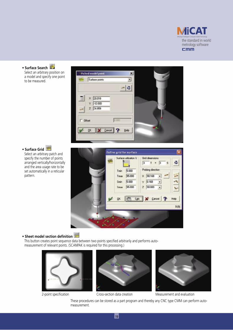
• Surface Search Select an arbitrary position on
a model and specify one point to be measured.
• Surface Grid Select an arbitrary patch and
specify the number of points arranged vertically/horizontally and the area usage rate to be set automatically in a reticular pattern.
These procedures can be stored as a part program and thereby any CNC type CMM can perform auto-measurement.
• Sheet model section definition This button creates point sequence data between two points specified arbitrarily and performs auto-
measurement of relevant points. (SCANPAK is required for this processing.)
2-point specification Cross-section data creation Measurement and evaluation
20
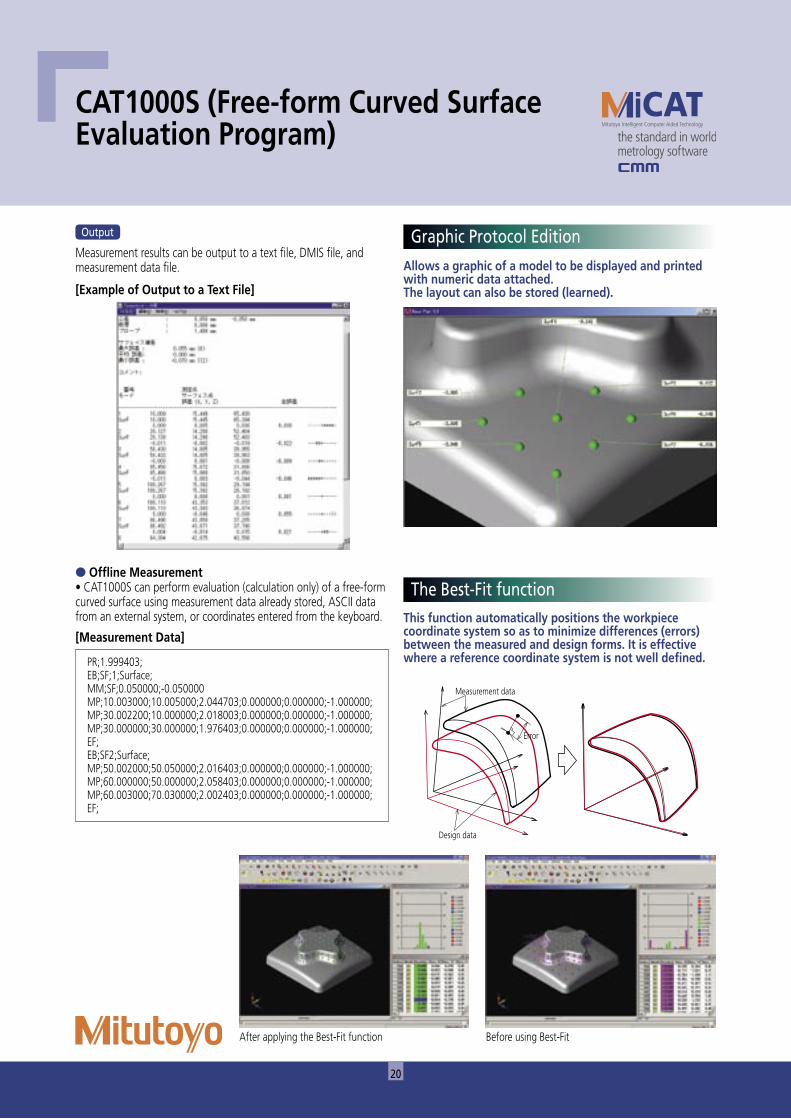
● Offline Measurement• CAT1000S can perform evaluation (calculation only) of a free-form curved surface using measurement data already stored, ASCII data from an external system, or coordinates entered from the keyboard. This function automatically positions the workpiece
coordinate system so as to minimize differences (errors) between the measured and design forms. It is effective where a reference coordinate system is not well defined.
Allows a graphic of a model to be displayed and printed with numeric data attached.The layout can also be stored (learned).
�����
����������������
�����������
Before using Best-FitAfter applying the Best-Fit function
PR;1.999403;EB;SF;1;Surface;MM;SF;0.050000;-0.050000MP;10.003000;10.005000;2.044703;0.000000;0.000000;-1.000000;MP;30.002200;10.000000;2.018003;0.000000;0.000000;-1.000000;MP;30.000000;30.000000;1.976403;0.000000;0.000000;-1.000000;EF;EB;SF2;Surface;MP;50.002000;50.050000;2.016403;0.000000;0.000000;-1.000000;MP;60.000000;50.000000;2.058403;0.000000;0.000000;-1.000000;MP;60.003000;70.030000;2.002403;0.000000;0.000000;-1.000000;EF;
CAT1000S (Free-form Curved Surface Evaluation Program)
[Measurement Data]
Graphic Protocol Edition
The Best-Fit function
[Example of Output to a Text File]
Measurement results can be output to a text file, DMIS file, and measurement data file.
Output

21
● Creating a part program from a CAD modelInstead of conventionally teaching (creating a part program) while operating the joystick, the program allows this work to be performed on a CAD model.● Operation manner compatible with GEOPAKThe CAT1000P screen configuration is compatible with GEOPAK and allows the operator to work with almost the same operating image as seen in GEOPAK when actually measuring with a CMM.
● Machine builderThis builder can easily configure a CMM by selecting the CMM model, the type of a master ball, probe changer, etc. and setting the corresponding locations on the table. It is possible to perform operation simulation and interference check of probe and workpiece, for the entire system configuration that has been created.
•Point •Line •Circle •Plane •Cone •Cylinder•Inclined circle •Rectangular hole •Slotted hole
This program reads model data (e.g. IGES) and displays it through MCOSMOS.CAT1000P allows mirror inversion of a model and thick plate setup (correcting an error by giving an offset if it is caused by a height difference between model data and the workpiece).
● Interference check functionAutomatically determines whether or not a programmed probe motion would cause an interference situation (collision) with a workpiece. This helps create safe part programs.
CAT1000P
���������� �������
���������
[Supported CAD Format]
● A rich choice of measuring elements
Loading CAD Data
CAT1000P is a simplified online/offline teaching program for creating a GEOPAK part program from model data output from a 3D-CAD system.
Operating feel identical to that of GEOPAK
Interference check function prevents collisions
Format Extension Supported version
IGES .igs/.ige/.iges V4.0/V5.2/V5.3
SAT .sat V16.0
VDAFS .vda/.vdafs V1.0/V2.0
STEP* .stp/.step AP203/AP214
CATIA V4* .exp V4.1.x – V4.2.4
CATIA V5* .CATPart/.CATProduct R2 – R17
PRO/E* .prt.1/.prt V16/Wildfire2/Wildfire3
Palasolid Part* .x_t/.xmt/.x_b 10.0 – 18.0
Unigraphics* .prt 11 – 18/NX1/NX2/NX3/NX4
SolidWorks* .sldprt/.prt 98 – 2006
*Option
22
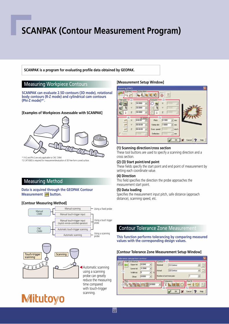
SCANPAK can evaluate 2.5D contours (3D mode), rotational body contours (R-Z mode) and cylindrical cam contours (Phi-Z mode)*1.
Data is acquired through the GEOPAK Contour Measurement button.
[Examples of Workpieces Assessable with SCANPAK]
[Contour Measuring Method]
*1 R-Z and Phi-Z are only applicable to CNC CMM.*2 CAT1000S is required for measurement/evaluation of 3D free-form curved surface.
��������� ��������������������������
��������������� ������������������
���������������������
���������������������������
�������
��������������������������������
������������������
����������������������������������������������������������������
����������������������
��������
[Measurement Setup Window]
SCANPAK (Contour Measurement Program)
This function performs tolerancing by comparing measured values with the corresponding design values.
[Contour Tolerance Zone Measurement Setup Window]
Contour Tolerance Zone Measurement
SCANPAK is a program for evaluating profile data obtained by GEOPAK.
Measuring Workpiece Contours
Measuring Method
Automatic scanning using a scanning probe can greatly reduce the measuring time compared with touch-trigger scanning.
(1) Scanning direction/cross sectionThese tool buttons are used to specify a scanning direction and a cross section.(2) (3) Start point/end pointThese fields specify the start point and end point of measurement by setting each coordinate value.(4) DirectionThis field specifies the direction the probe approaches the measurement start point.(5) Data loadingSpecifies the measurement input pitch, safe distance (approach distance), scanning speed, etc.
(1)
(2) (3)
(4) (5)
(1)
(2)
(3)(4) (5)
23
������������������������������������������������������������������������������
�����������������������������������
����������������������
�������������
����������������������
����������������������
�����������������������������������
����������������������������������������������������
���������������������������������������������������������������
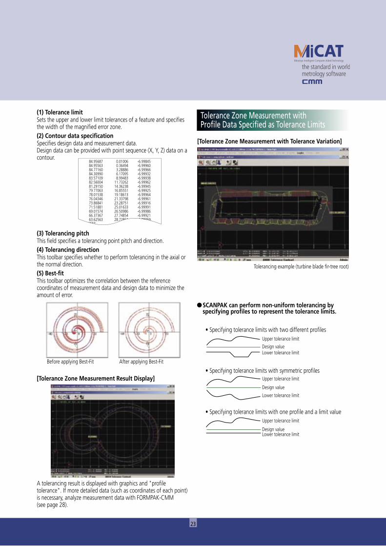
[Tolerance Zone Measurement with Tolerance Variation]
● SCANPAK can perform non-uniform tolerancing by specifying profiles to represent the tolerance limits.
Tolerancing example (turbine blade fir-tree root)
A tolerancing result is displayed with graphics and "profile tolerance". If more detailed data (such as coordinates of each point) is necessary, analyze measurement data with FORMPAK-CMM (see page 28).
[Tolerance Zone Measurement Result Display]
(1) Tolerance limitSets the upper and lower limit tolerances of a feature and specifies the width of the magnified error zone.(2) Contour data specificationSpecifies design data and measurement data.Design data can be provided with point sequence (X, Y, Z) data on a contour.
(3) Tolerancing pitchThis field specifies a tolerancing point pitch and direction.(4) Tolerancing directionThis toolbar specifies whether to perform tolerancing in the axial or the normal direction.(5) Best-fitThis toolbar optimizes the correlation between the reference coordinates of measurement data and design data to minimize the amount of error.
Before applying Best-Fit After applying Best-Fit
��������� �������� ����������������� �������� ����������������� �������� ����������������� �������� ����������������� �������� ����������������� ��������� ����������������� ��������� ����������������� ��������� ����������������� ��������� ����������������� ��������� ����������������� ��������� ����������������� ��������� ����������������� ��������� ����������������� ��������� ����������������� ��������� ��������
���������� � ��������
Tolerance Zone Measurement with Profile Data Specified as Tolerance Limits
24
�����������������������������������������������������������������������������������������������������������������������������������������������������������
���������������
���������������
���������������
���������������
��������������������
���������������������������������������������������������������������������������������������������������������������������������������������������������������������������������������������������������������������������������������������������������������������������������������������������������������������������������������������������������������������������������
�������������������������������������������������������������������������������������������������������������������������������������������������������������������������
������������������������������������������
���������������
���������������
��������������������
���������������������
����������
���������������������
��������������������
���������������
��������������������������
���������������
���������������
���������������
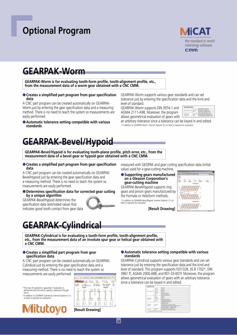
● Creates a simplified part program from gear specification data
A CNC part program can be created automatically on GEARPAK-Cylindical just by entering the gear specification data and a measuring method. There is no need to teach the system so measurements are easily performed.
* The new JIS standard is supported. If evaluation is performed with the old JIS, specify a tolerance through key-in.
* In addition to GEARPAK-Cylindrical, Internet Explore (r 5.x or later) is required for evaluation.
[Result Drawing]
GEARPAK-Cylindrical
● Creates a simplified part program from gear specification data
A CNC part program can be created automatically on GEARPAK-Worm just by entering the gear specification data and a measuring method. There is no need to teach the system so measurements are easily performed.● Automatic tolerance setting compatible with various
standards
GEARPAK-Worm
● Creates a simplified part program from gear specification data
A CNC part program can be created automatically on GEARPAK-Bevel/Hypoid just by entering the gear specification data and a measuring method. There is no need to teach the system so measurements are easily performed.● Determines specification data for corrected gear cutting
by a unique algorithmGEARPAK-Bevel/Hypoid determines the specification data (estimated value) that indicates good tooth contact from gear data [Result Drawing]
GEARPAK-Bevel/Hypoid
Optional Program
GEARPAK-Worm is for evaluating tooth-form profile, tooth-alignment profile, etc., from the measurement data of a worm gear obtained with a CNC CMM.
GEARPAK-Worm supports various gear standards and can set tolerance just by entering the specification data and the kind and level of standard.GEARPAK-Worm supports DIN 3974-1 and AGMA 2111-A98. Moreover, the program allows geometrical evaluation of gears with an arbitrary tolerance since a tolerance can be keyed in and edited.* In addition to GEARPAK-Worm, Internet Explorer (5.x or later) is required for evaluation.
measured with GEOPAK and gear cutting specification data (initial value) used for a gear-cutting machine.● Supporting gears manufactured
on a Gleason Corporation's gear-cutting machine
GEARPAK-Bevel/Hypoid supports ring gears and pinion gears manufactured by the Formate or Helixform methods.* In addition to GEARPAK-Bevel/Hypoid, Internet Explore (r 5.x or later) is required for evaluation.
GEARPAK-Cylindrical is for evaluating a tooth-form profile, tooth-alignment profile, etc., from the measurement data of an involute spur gear or helical gear obtained with a CNC CMM.
● Automatic tolerance setting compatible with various standards
GEARPAK-Cylindrical supports various gear standards and can set tolerance just by entering the specification data and the kind and level of standard. This program supports ISO1328, JIS B 1702*, DIN 3961 ff, AGMA 2000-A88, and R01-33-001F. Moreover, the program allows geometrical evaluation of gears with an arbitrary tolerance since a tolerance can be keyed in and edited.
GEARPAK-Bevel/Hypoid is for evaluating tooth-plane profile, pitch error, etc., from the measurement data of a bevel gear or hypoid gear obtained with a CNC CMM.
25
��������
����������
��������������������������������������������������������������������������������������
�����������
�������������������
������
���������������������
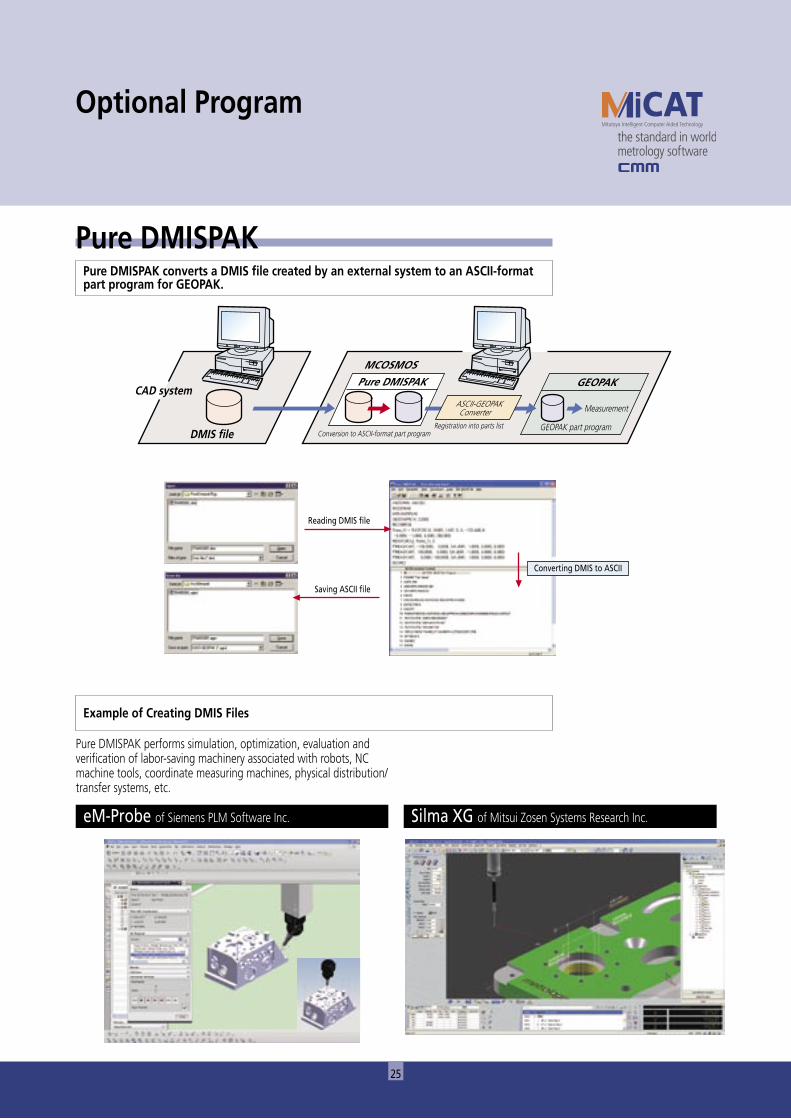
Pure DMISPAKPure DMISPAK converts a DMIS file created by an external system to an ASCII-format part program for GEOPAK.
Optional Program
Pure DMISPAK performs simulation, optimization, evaluation and verification of labor-saving machinery associated with robots, NC machine tools, coordinate measuring machines, physical distribution/transfer systems, etc.
Example of Creating DMIS Files
eM-Probe of Siemens PLM Software Inc. Silma XG of Mitsui Zosen Systems Research Inc.
Converting DMIS to ASCII
Reading DMIS file
Saving ASCII file
26
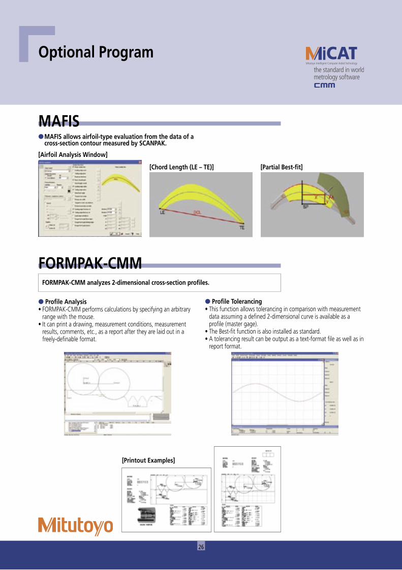
● Profile Analysis• FORMPAK-CMM performs calculations by specifying an arbitrary
range with the mouse.• It can print a drawing, measurement conditions, measurement
results, comments, etc., as a report after they are laid out in a freely-definable format.
● Profile Tolerancing• This function allows tolerancing in comparison with measurement
data assuming a defined 2-dimensional curve is available as a profile (master gage).
• The Best-fit function is also installed as standard.• A tolerancing result can be output as a text-format file as well as in
report format.
[Printout Examples]
FORMPAK-CMM
Optional Program
FORMPAK-CMM analyzes 2-dimensional cross-section profiles.
[Airfoil Analysis Window]
[Chord Length (LE – TE)]
MAFIS● MAFIS allows airfoil-type evaluation from the data of a
cross-section contour measured by SCANPAK.
[Partial Best-fit]
27
Measurement result fi le
File conversion Generation of inspection table
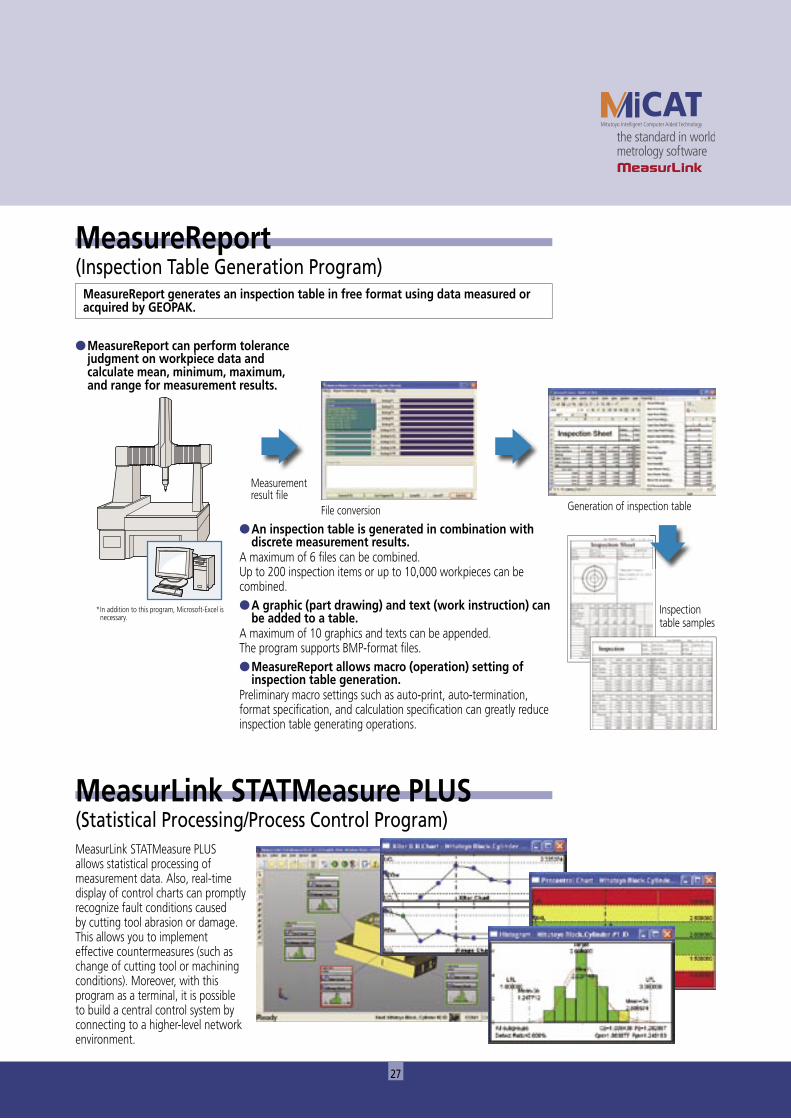
● MeasureReport can perform tolerance judgment on workpiece data and calculate mean, minimum, maximum, and range for measurement results.
● An inspection table is generated in combination with discrete measurement results.
A maximum of 6 fi les can be combined.Up to 200 inspection items or up to 10,000 workpieces can be combined.● A graphic (part drawing) and text (work instruction) can
be added to a table.A maximum of 10 graphics and texts can be appended.The program supports BMP-format fi les.● MeasureReport allows macro (operation) setting of
inspection table generation.Preliminary macro settings such as auto-print, auto-termination, format specifi cation, and calculation specifi cation can greatly reduce inspection table generating operations.
Inspection table samples
MeasureReport generates an inspection table in free format using data measured or acquired by GEOPAK.
MeasureReport (Inspection Table Generation Program)
MeasurLink STATMeasure PLUS allows statistical processing of measurement data. Also, real-time display of control charts can promptly recognize fault conditions caused by cutting tool abrasion or damage. This allows you to implement effective countermeasures (such as change of cutting tool or machining conditions). Moreover, with this program as a terminal, it is possible to build a central control system by connecting to a higher-level network environment.
MeasurLink STATMeasure PLUS (Statistical Processing/Process Control Program)
* In addition to this program, Microsoft-Excel is necessary.
�����������������������������������������
������������������������������
�����������������������������
�����������������������������
��������������
�����������������
����������������
������������������������
Note: All information regarding our products, and in particular the illustrations, drawings, dimensional and performance data contained in this pamphlet, as well as other technical data are to be regarded as approximate average values. We therefore reserve the right to make changes to the corresponding designs, dimensions and weights. The stated standards, similar technical regulations, descriptions and illustrations of the products were valid at the time of printing. Only quotations submitted by ourselves may be regarded as definitive.Our products are classed as regulated items under Japanese Foreign Exchange and Foreign Trade Law. Please consult us in advance if you wish to export our products to any other country. If the purchased product is exported, even though it is not a regulated item (Catch-All controls item), the customer service available for that product may be affected. If you have any questions, please consult your local Mitutoyo sales office.
Export permission by the Japanese government may be required for exporting our products according to the Foreign Exchange and Foreign Trade Law. Please consult our sales office near you before you export our products or you offer technical information to a nonresident.
76.8
3 09
02 (4
) C-(W
Z)HS
. Prin
ted
in Ja
pan
Specifications are subject to change without notice.