mcquay suite type n top mounted hydronic heat
TRANSCRIPT

McQuay Suite Type NTop Mounted Hydronic HeatIncremental® Packaged TerminalAir Conditioners
C: 1355-4
Page 2 / Catalog 1355-4 (Rev. 5/99)
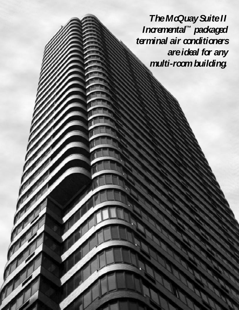
The McQuay Suite IIIncremental™ packaged
terminal air conditionersare ideal for any
multi-room building.

Catalog 1355-4 / Page 3 (Rev. 5/99)
McQuay Suite satisfies the most critical concerns in thecommercial heating, ventilating and air conditioning industry.
• Design superiority• Installation simplicity• High efficiency
Inherent economy
"McQuay" and "Incremental" are registered trademarks of AAF–McQuay Incorporated, Minneapolis, MN."Suite" is a trademark of AAF–McQuay Incorporated, Minneapolis, MN.
©1996 AAF–McQuay Incorporated. All rights reserved throughout the world.
"Bulletin illustrations cover the general appearance of AAF–McQuay Incorporated products at the time of publication and we reserve the right to make changes in design and construction at any time without notice." (9/96)
The Incremental conditioner’s approach to HVAC has been ac-knowledged as a highly attractive and efficient option in heatingand cooling multi-room buildings for over thirty years.
The Incremental system is a perimeter system of completefour-season air conditioning to condition the exterior spaces ofmulti-room, multi-story buildings. Now it is possible to apply thistechnology in new or existing installation sites easily, efficientlyand economically. This is accomplished with the new McQuaySuite Incremental packaged terminal air conditioner (PTAC).
The new Suite conditioner incorporates state-of-the-art fea-tures and controls to meet the demands of the commercial HVACmarket. Every standard Suite conditioner is UL listed and ARIcertified for capacity and operating efficiency.
Maximum utility and economyin a new multi-room buildingDesigning a new building around the McQuay Suite packagedterminal air conditioner assures economy and efficiency for yearsto come. Design flexibility and maximum system control is avail-able to the owner through the use of an integrated Mcauay en-ergy management system. This system offers building designersand management the ability to chart and plan energy usage,automatically regulate temperature ranges, and furnish a varietyof building function controls with optional, special purpose de-vices.
Retrofit the new Suite in multi-room buildingsOutdated PTAC systems provide insufficient comfort levels. Many
are noisy, leak condensate, have poor efficiencies and are noteasily controlled by the occupant or owner. A principal benefit ofthe Suite unit is the ease at which the changeover can be ac-complished. No costly, disruptive construction is necessary. Anefficient Suite chassis can be easily slid into most existing wallsleeves to replace that outdated, inefficient PTAC unit previouslypurchased from other major manufacturers.
Unsurpassed performance and reliabilityPerformance of the Suite is smooth and trouble-free. Easy-to-reach coil surfaces allow the unit to be cleaned without shred-ding or compacting the fins. Performance standards remain highover long years of service.
This combination of efficiency, economy and reliability is onlyavailable through McQuay conditioners. The new Suite Incremen-tal packaged terminal air conditioner and packaged terminal heatpump incorporate the benefits of:
• Higher EER’s• ARI certified and U.L. listed• Clean cabinet design• No construction expense or mess• Very competitive price
Superior design and high quailty constructionHigh standards of design and construction assure reliable op-eration in all seasons. Over three decades of use attest to thedurability and reliability of the finely engineered Mcouay Incre-mental packaged terminal unit.

Page 4 / Catalog 1355-4 (Rev. 5/99)
Wrap-around EnclosureThis attractive cabinet enclosure is furnished
with a corrosion resistant Antique Ivory finish.The oversized enclosure completely
encompasses controls and piping to leave anattractive appearance to the occupant. The
front panel of this enclosure is removable toallow access to controls, piping and the 1/2”
permanent, cleanable filter.
McQuay Suite: A new generation of featuresA new generation of technology... McQuay’s engineering departments began the design of theSuite conditioner with a comprehensive study of the most widely used components in the industry.Strengths and weaknesses of each were assessed and analyzed. The selection of Suite componentswas made to optimize the performance of each of our four basic sizes.
Evaporator and Condenser Coil.These high capacity coils employ the latest
in heat transfer technology. The unique finand tube design provides maximum
comfort to the conditioned space whilesimultaneously minimizing the energy
required to operate the unit.

Catalog 1355-4 / Page 5 (Rev. 5/99)
Control Module. Energy savings is inherent in thestandard control panel. It is furnished with a “fan only”control to circulate the air without operating the heatingor cooling functions. The control panel also employs ourexclusive temperature limiting feature which allows theowner to preset the minimum and maximum limits toassure total energy savings.
Heating Coil Assembly. The unique mounting arrange-ment of this high capacity hydronic coil allows for easyinstallation at the precise time. The assembly quickly andrigidly snaps into slots provided in the wall sleeve. Providedare 5/8” O.D. copper connections for left-hand (LH), right-hand (RH) or opposite end piping.
Compressor. The quiet operating, highefficiency compressor is built to meet strictengineering and design specifications, and hasan endurance measurable in decades. Thecompressor is hermetically sealed and de-signed for continuous, quiet operation, pluseach compressor is isolated to minimizevibration and sound transmission.
Wall Sleeve. This sturdy sleeve is made ofheavy-gauge sheet steel, dipped in EHBPthermosetting plastic, then baked at a hightemperature for maximum corrosionprotection. The wall sleeve is supplied withan internal vertical support for use until themortar dries. A waxed, temporary weatherpanel is furnished to keep out the elementsduring construction.
Cooling Chassis. The slide-out chassis in-corporated in the Suite conditioner is specificallydesigned to simplify maintenance. The chassishouses two quiet-running fans and motors whichallow for air circulation without excessive noisediscomfort to the room occupants.

Page 6 / Catalog 1355-4 (Rev. 5/99)
Performance and electrical data
Notes:1. Wall opening shall be a minimum of 161/4” high by 421/4” wide and
must provide a minimum clearance of 3” from finished floor to thebottom of the wall sleeve.
2. Masonry support must be left in wall sleeve until mortar hasthoroughly dried.
3. The weather panel provided with separate shipment of cabinet/wallsleeve. This panel provides a weather seal prior to installation of thechassis. Remove the panel before installing the chassis.
4. Wall sleeve should be installed level side-to-side, and inside-to-out-side.
5. Cabinet depth and wall sleeve depth are factory adjustable (as shownabove) to accommodate various wall thicknesses. Refer to certifieddrawing for more details.
➀ Based on ASHRAE and ARI test conditions of 95 F DB/75 F WB outside, 80 F DB/67 F WB inside.➁ Performance data based on low fan speed.➂ Based on 200 F EWT, 20 F DT — 70 F EAT; 2 psig steam — 70 F EAT.④ Type HACR circuit breaker.
Volts
Minim um Cir cuit Ampacity
Delay Fuse or Cir cuit Breaker ④
Receptac le Required, NEMA No.
Total Shipping Weight (Lbs.)
007 ➀ ➁
7,300
10.3
115V 208V 230V 265V
6.5 3.6 3.3 2.8
710 710 710 710
.95 .95 .95 .95
195 / 60
180 / 40
205 / 60
190 / 40
.80 .43
21,200 / 18,000
23,300 / 19,800
115V 208V 230V 265V
20 20 20 20
15 15 15 15
5-20R 6-20R 6-20R —––
284
UNIT SIZE
Btuh
EER
Volts
Full Load Amps
Watts
Power Factor , %
High Cool
Low
High Heat
Low Heat
Full Load Amps
Hot Water High/Lo w
Steam High/Lo w
009 ➀
9,200
9.9
115V 208V 230V 265V
8.6 4.7 4.3 3.7
930 930 930 930
.94 .94 .94 .94
185 / 60
175 / 40
205 / 60
190 / 40
.80 .43
21,200 / 18,000
23,300 / 19,800
115V 208V 230V 265V
20 20 20 20
15 15 15 15
5-20R 6-20R 6-20R ––––
288
012 ➀ ➁
12,100
10.3
208V 230V 265V
6.0 5.4 4.7
1175 1175 1175
.95 .95 .95
300 / 70
275 / 50
330 / 70
305 / 50
.82
24,500 / 20,700
26,300 / 22,300
208V 230V 265V
20 20 20
15 15 15
6-20R 6-20R –—–
292
015 ➀
14,600
9.6
208V 230V 265V
7.6 6.9 6.0
1521 1521 1521
.96 .96 .96
295 / 70
270 / 50
340 / 70
315 / 50
.82
24,500 / 20,700
26,300 / 22,300
208V 230V 265V
20 20 20
15 15 15
6-20R 6-20R ––—
296
Cooling
Airflo w
Cfm
Total / Vent
Heating
Heating
Btuh ➂
Dimensional data
25 64
GRGRGR
5-20R20 Amp, 120V
6-20R20 Amp, 250V
7-20R1 / " Dia., 265V
Nema Receptac les
NOTE: 265V Unit Requires subbase,part number 0061325001.
ALL DIMENSIONS IN INCHES
B

Catalog 1355-4 / Page 7 (Rev. 5/99)
Engineering guide specificationsFurnish and install where shown on plans packaged terminal air conditioners of the sizes and capacities shown on the schedule. Theunits shall be located as shown on the drawings and shall include cabinet/wall sleeve, chassis, outdoor louver, hydronic heat section,valve, and room cabinet.
All units shall be U.L. listed for safety and ARI certified for performance. Overall dimensions for the basic unit shall not exceed 52”wide, 221/2” high, and 173/4” deep. (Overall dimensions of the wall sleeve shall not exceed 16” high, 42” wide and 133/4” deep.)
All units shall operate on _________ volts, 60 Hz, 1 phase power.The minimum energy efficiency ratio in Btu per hour per watt for each unit must be 8.9 for all sizes.
Heating/Cooling Chassis — Chassis shall be slide-in, plug-in type with a self-contained, hermetically sealed, refrigerant circuit. Allchassis sheet metal parts shall be constructed of heavy-gauge galvanized steel for maximum corrosion resistance. The chassis shallconsist of the following components:
Vibration isolated compressor; rifled copper tubed evaporator and condenser coils with high efficiency aluminum plate fins me-chanically expanded to the tubes for maximum heat transfer; and a capillary restrictor type refrigerant metering device. Coils shall befactory tested at 300 psig.
Airflow system shall consist of a separate, single speed, totally enclosed fan cooled, PSC, outdoor condenser motor. Condenserfan shall be made of high impact resistant polymer and shall be propeller type without a slinger ring. Indoor fan motor shall be two-speed and shall be separate from the outdoor condenser fan motor. Single motor units serving both condenser and evaporatorsections are not acceptable. The indoor fan motor must be positioned on the indoor side of the bulkhead so as to be completely withinthe conditioned, filtered airstream. Both the indoor and outdoor fan motors shall be permanently lubricated type with external oilers forprolonged life. Indoor fans shall be forwardly curved centrifugal type to provide even airflow across the evaporator coil.
During The Cooling Cycle — The compressor, the outdoor fan motor and the indoor fan motor shall be energized. Condensationaccumulated on the evaporator coil shall be drained into the outdoor section where it is to be picked up by the condenser fan andevaporated against the outdoor coil.
During The Heating Cycle (Hydronic Heat) — Only the indoor fan motor, the (normally open)(normally closed) valve and automaticfresh air damper shall be energized. Outdoor condenser fan motor and compressor shall not be energized.
Control Module — Shall have a six (6) button selector switch containing Off-Heat-Cool-High-Low-Fan and a self-contained, adjust-able thermostat with a field adjustable temperature limiting device. A fan cycle shall be incorporated to allow constant fan operation orintermittent fan operation. Intermittent fan operation shall allow the fan to energize upon a demand for heating or cooling.
Room Cabinet — Shall be flat top, wrap-around design with a heavy-gauge sheet metal front panel that is phosphatized and coatedwith a baked on, Antique Ivory corrosion resistant finish. Discharge grilles shall be tamper-proof. The control access door shall bemounted on the right-hand side. (Access door shall be furnished with a keylock device to prevent unauthorized tampering.)
Fresh Air Damper — A positive closing (manual/automatic) fresh air damper must be located within the chassis to provide fresh airduring fan operation.
Filtration — Shall be accomplished using a permanent, aluminum mesh, cleanable filter. Washable foam type filters are not accept-able. Filters must be concealed but easily accessible for scheduled maintenance. Return air shall enter the filter from the bottom of thechassis. A louvered front panel is unacceptable.
Wall Sleeve — Shall be entirely constructed of galvanized, phosphatized, heavy-gauge steel with a baked Antique Ivory corrosionresistant finish. Wall sleeves with ordinary enamel finish are not acceptable. Wall sleeves shall be installed a minimum of 4” above thefloor. Wall sleeves shall be installed through the wall as shown on plans and shall have factory provisions for use of appropriatefastening devices to secure sleeve to the wall. In no event shall fasteners be installed through the basepan in the bottom of the cabinet/wall sleeve.
Outside Air Louvers — Shall be (stamped)(architectural) anodized aluminum as shown on plans. Louver shall be (finishednatural)(painted) as shown on the schedule. Louvers shall be easily installed from the inside of the building after the cabinet/wallsleeve has been installed. Special field fabricated louvers must be approved by the PTAC manufacturer as to free area and aircirculation requirements.

Contact your McQuay representative today.
©1999 AAF–McQuay Incorporated
4900 Technology Park Boulevard, Auburn, New York 13021-9030 USA (315) 253-2771
Printed on recycled paper containing at least 10% post-consumer recycled material.