mcs synchronous servo motors - gerit.it · the scope of our program includes ... 1-4...
TRANSCRIPT
Dynamic, compact, reliable
MCS synchronous servo motors
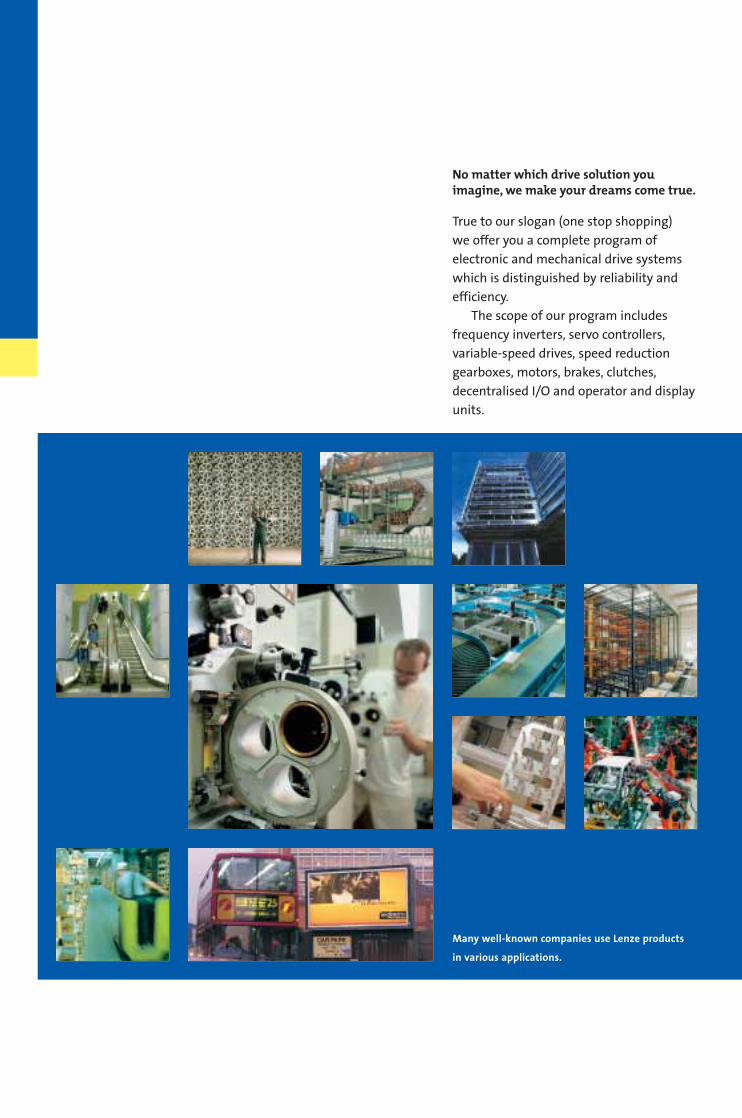
No matter which drive solution you imagine, we make your dreams come true.
True to our slogan (one stop shopping)
we offer you a complete program of
electronic and mechanical drive systems
which is distinguished by reliability and
efficiency.
The scope of our program includes
frequency inverters, servo controllers,
variable-speed drives, speed reduction
gearboxes, motors, brakes, clutches,
decentralised I/O and operator and display
units.
Many well-known companies use Lenze products
in various applications.
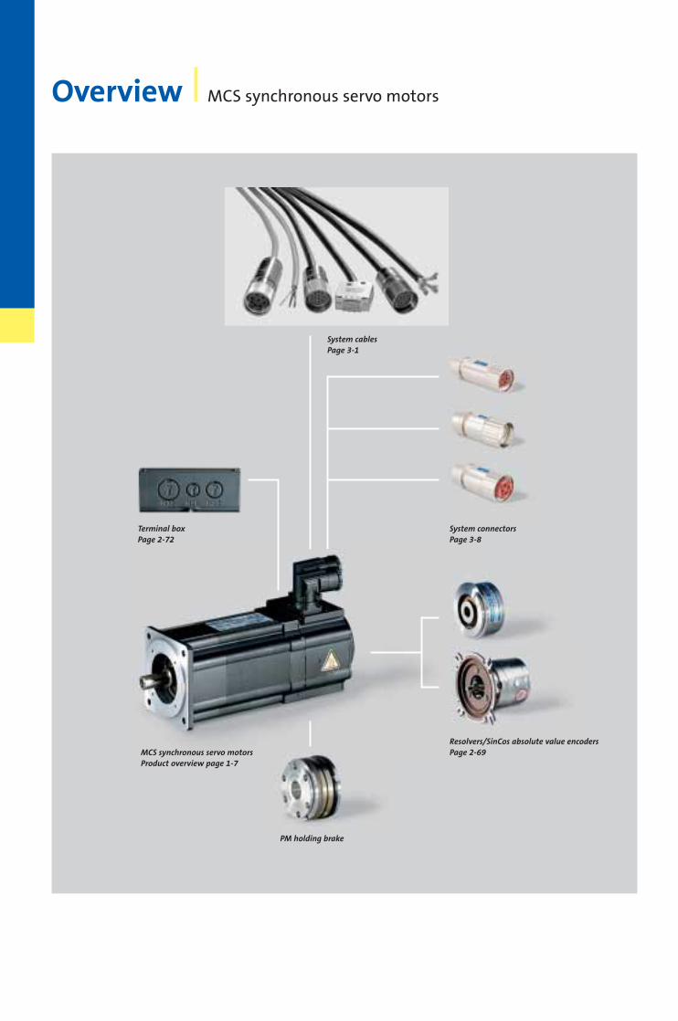
Overview MCS synchronous servo motors
Terminal boxPage 2-72
System cablesPage 3-1
MCS synchronous servo motorsProduct overview page 1-7
System connectorsPage 3-8
Resolvers/SinCos absolute value encodersPage 2-69
PM holding brake
MCS synchronous servo motors Dynamic,compact, reliable
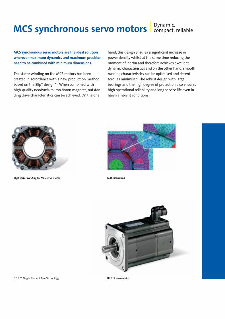
MCS synchronous servo motors are the ideal solution
wherever maximum dynamics and maximum precision
need to be combined with minimum dimensions.
The stator winding on the MCS motors has been
created in accordance with a new production method
based on the SEpT design *). When combined with
high-quality neodymium iron boron magnets, outstan-
ding drive characteristics can be achieved. On the one
hand, this design ensures a significant increase in
power density whilst at the same time reducing the
moment of inertia and therefore achieves excellent
dynamic characteristics and on the other hand, smooth
running characteristics can be optimised and detent
torques minimised. The robust design with large
bearings and the high degree of protection also ensures
high operational reliability and long service life even in
harsh ambient conditions.
MCS 14 servo motor
FEM calculationSEpT stator winding for MCS servo motor
*) SEpT: Single Element Pole Technology
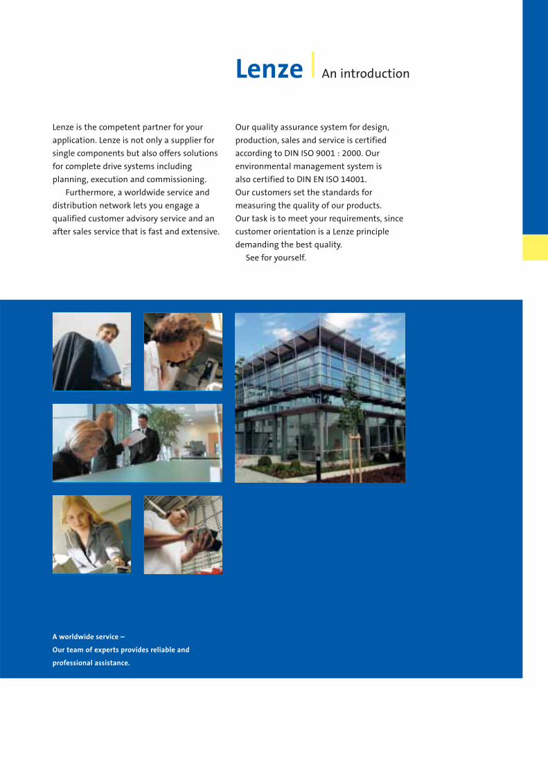
A worldwide service –
Our team of experts provides reliable and
professional assistance.
Lenze An introduction
Lenze is the competent partner for your
application. Lenze is not only a supplier for
single components but also offers solutions
for complete drive systems including
planning, execution and commissioning.
Furthermore, a worldwide service and
distribution network lets you engage a
qualified customer advisory service and an
after sales service that is fast and extensive.
Our quality assurance system for design,
production, sales and service is certified
according to DIN ISO 9001 : 2000. Our
environmental management system is
also certified to DIN EN ISO 14001.
Our customers set the standards for
measuring the quality of our products.
Our task is to meet your requirements, since
customer orientation is a Lenze principle
demanding the best quality.
See for yourself.
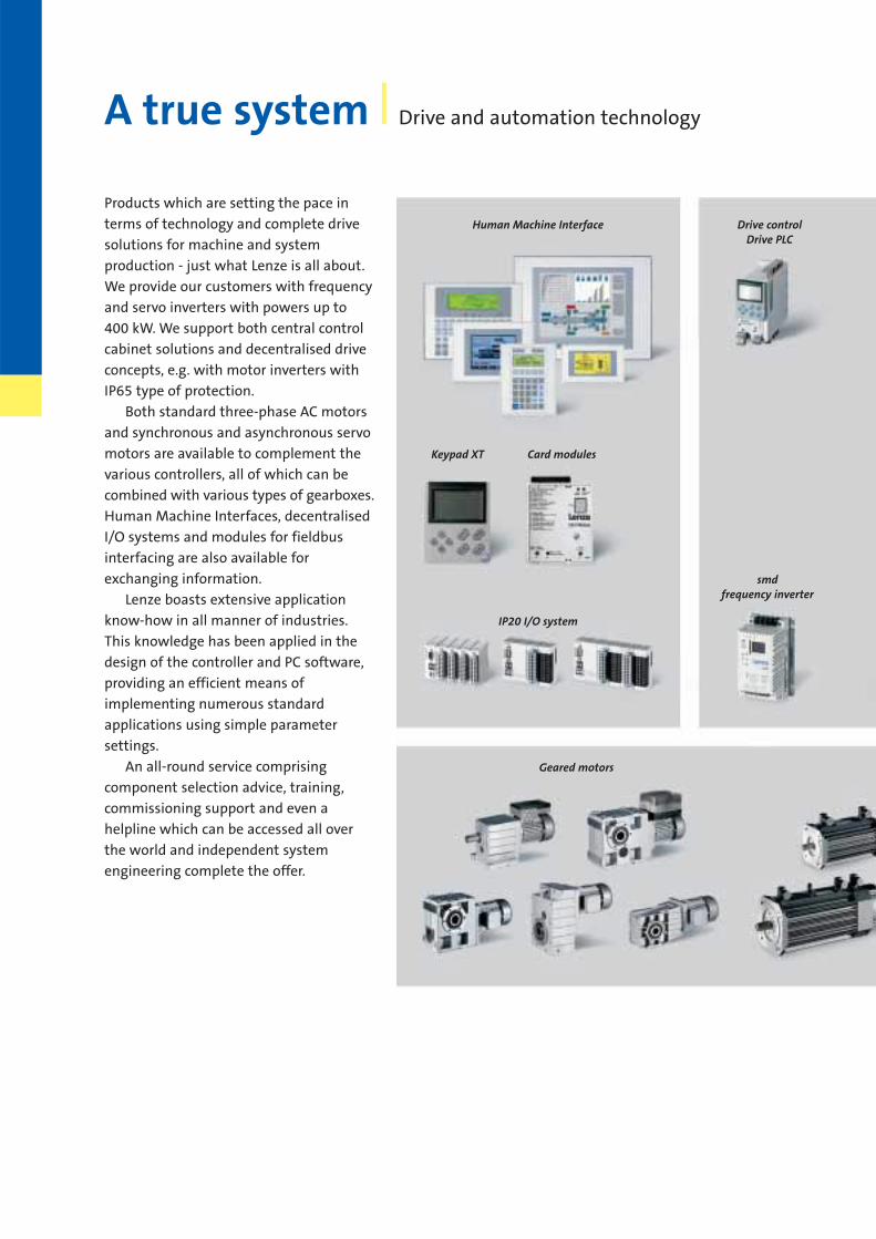
Products which are setting the pace in
terms of technology and complete drive
solutions for machine and system
production - just what Lenze is all about.
We provide our customers with frequency
and servo inverters with powers up to
400 kW. We support both central control
cabinet solutions and decentralised drive
concepts, e.g. with motor inverters with
IP65 type of protection.
Both standard three-phase AC motors
and synchronous and asynchronous servo
motors are available to complement the
various controllers, all of which can be
combined with various types of gearboxes.
Human Machine Interfaces, decentralised
I/O systems and modules for fieldbus
interfacing are also available for
exchanging information.
Lenze boasts extensive application
know-how in all manner of industries.
This knowledge has been applied in the
design of the controller and PC software,
providing an efficient means of
implementing numerous standard
applications using simple parameter
settings.
An all-round service comprising
component selection advice, training,
commissioning support and even a
helpline which can be accessed all over
the world and independent system
engineering complete the offer.
A true system Drive and automation technology
Human Machine Interface Drive controlDrive PLC
smdfrequency inverter
Keypad XT Card modules
Geared motors
IP20 I/O system
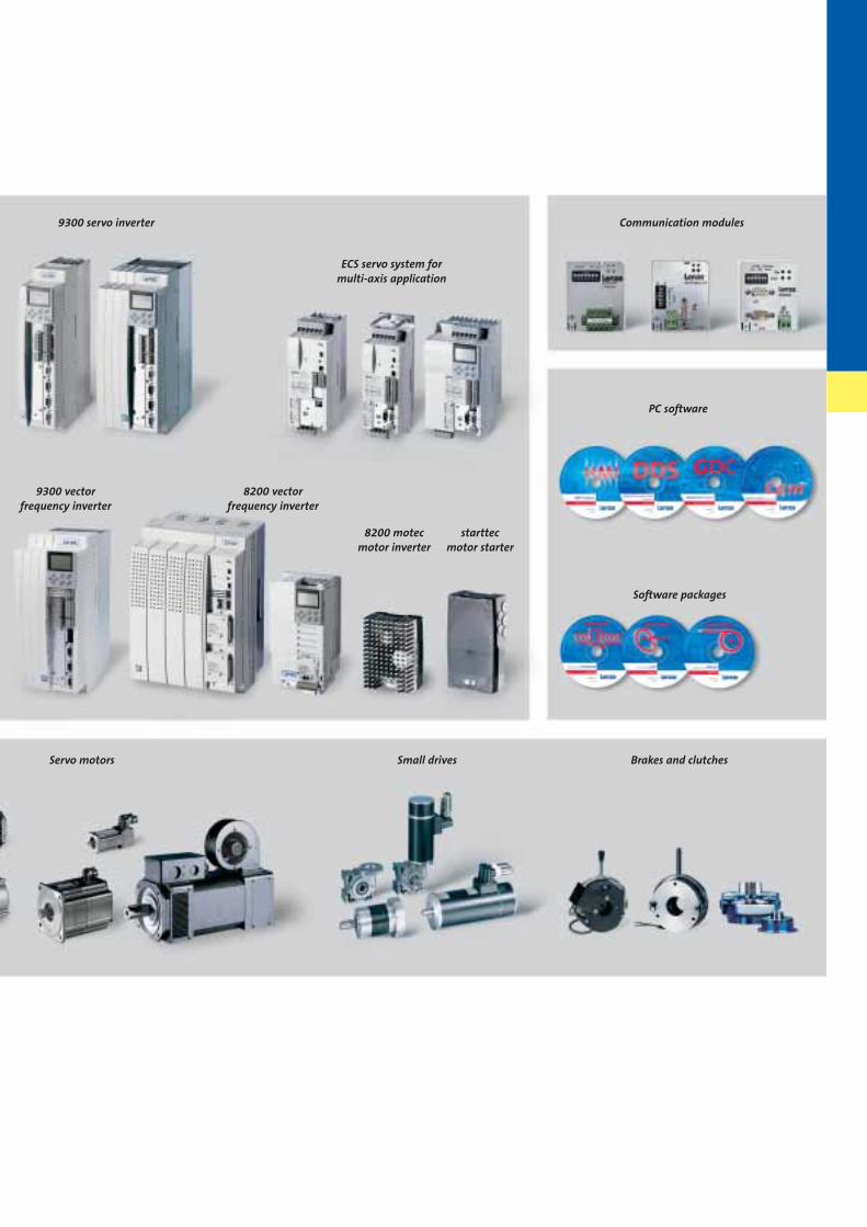
9300 servo inverter
9300 vectorfrequency inverter
8200 vectorfrequency inverter
8200 motec motor inverter
starttecmotor starter
ECS servo system formulti-axis application
Communication modules
PC software
Software packages
Servo motors Small drives Brakes and clutches
1
2
3
4
Accessories 3-1
Services 4-1
Product codes 4-4
Contents
Technical data 2-1
MCS 06 synchronous servo motor 2-3
MCS 09 synchronous servo motor 2-17
MCS 12 synchronous servo motor 2-29
MCS 14 synchronous servo motor 2-41
MCS 19 synchronous servo motor 2-55
Options 2-68
General 1-1
Overview of MCS synchronous servo motors 1-7
MCS synchronousservo motors
1-1Synchron-Servomotoren MCS en 4/2004
General MCS synchronous servo motors
List of abbreviations1-3
Product information
MCS synchronous servo motors 1-4Version overview 1-6MCS synchronous servo motors product overview 1-7General data 1-8Influence of ambient temperatureand installation height 1-9Drive dimensioning __________ 1-10
1

1-2 Synchron-Servomotoren MCS en 4/2004
1
GeneralList of abbreviations
1-3Synchron-Servomotoren MCS en 4/2004
1
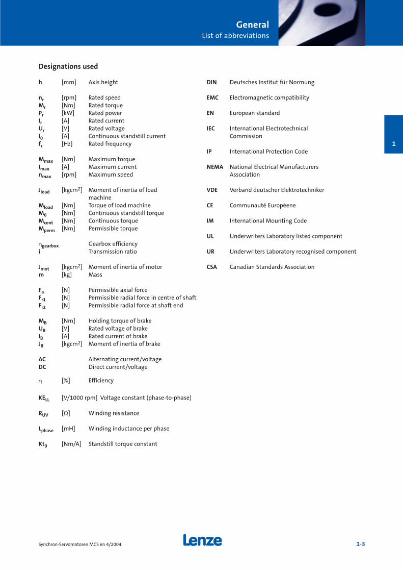
Designations used
h [mm] Axis height
nr [rpm] Rated speedMr [Nm] Rated torquePr [kW] Rated powerIr [A] Rated currentUr [V] Rated voltageI0 [A] Continuous standstill currentfr [Hz] Rated frequency
Mmax [Nm] Maximum torqueImax [A] Maximum currentnmax [rpm] Maximum speed
Jload [kgcm2] Moment of inertia of loadmachine
Mload [Nm] Torque of load machineM0 [Nm] Continuous standstill torqueMcont [Nm] Continuous torqueMperm [Nm] Permissible torque
gearbox Gearbox efficiencyi Transmission ratio
Jmot [kgcm2] Moment of inertia of motorm [kg] Mass
Fa [N] Permissible axial forceFr1 [N] Permissible radial force in centre of shaftFr2 [N] Permissible radial force at shaft end
MB [Nm] Holding torque of brakeUB [V] Rated voltage of brakeIB [A] Rated current of brakeJB [kgcm2] Moment of inertia of brake
AC Alternating current/voltageDC Direct current/voltage
[%] Efficiency
KELL [V/1000 rpm] Voltage constant (phase-to-phase)
RUV [Ω] Winding resistance
Lphase [mH] Winding inductance per phase
Kt0 [Nm/A] Standstill torque constant
DIN Deutsches Institut für Normung
EMC Electromagnetic compatibility
EN European standard
IEC International Electrotechnical Commission
IP International Protection Code
NEMA National Electrical Manufacturers Association
VDE Verband deutscher Elektrotechniker
CE Communauté Européene
IM International Mounting Code
UL Underwriters Laboratory listed component
UR Underwriters Laboratory recognised component
CSA Canadian Standards Association
GeneralProduct information
1-4 Synchron-Servomotoren MCS en 4/2004
1
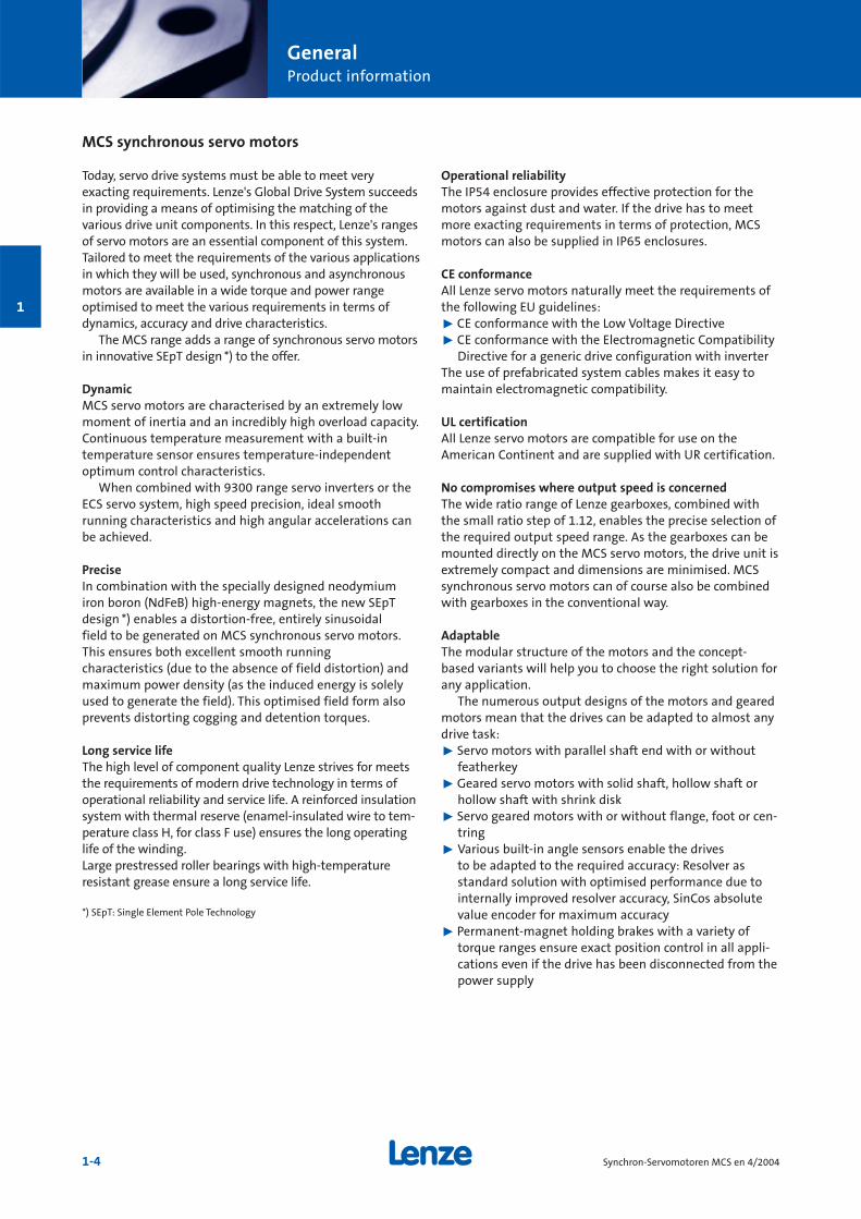
MCS synchronous servo motors
Today, servo drive systems must be able to meet very exacting requirements. Lenze's Global Drive System succeedsin providing a means of optimising the matching of thevarious drive unit components. In this respect, Lenze's rangesof servo motors are an essential component of this system.Tailored to meet the requirements of the various applicationsin which they will be used, synchronous and asynchronousmotors are available in a wide torque and power range optimised to meet the various requirements in terms ofdynamics, accuracy and drive characteristics.
The MCS range adds a range of synchronous servo motorsin innovative SEpT design *) to the offer.
DynamicMCS servo motors are characterised by an extremely lowmoment of inertia and an incredibly high overload capacity.Continuous temperature measurement with a built-intemperature sensor ensures temperature-independentoptimum control characteristics.
When combined with 9300 range servo inverters or theECS servo system, high speed precision, ideal smoothrunning characteristics and high angular accelerations canbe achieved.
PreciseIn combination with the specially designed neodymiumiron boron (NdFeB) high-energy magnets, the new SEpTdesign *) enables a distortion-free, entirely sinusoidal field to be generated on MCS synchronous servo motors.This ensures both excellent smooth running characteristics (due to the absence of field distortion) andmaximum power density (as the induced energy is solelyused to generate the field). This optimised field form alsoprevents distorting cogging and detention torques.
Long service lifeThe high level of component quality Lenze strives for meetsthe requirements of modern drive technology in terms ofoperational reliability and service life. A reinforced insulationsystem with thermal reserve (enamel-insulated wire to tem-perature class H, for class F use) ensures the long operatinglife of the winding.Large prestressed roller bearings with high-temperature resistant grease ensure a long service life.
*) SEpT: Single Element Pole Technology
Operational reliabilityThe IP54 enclosure provides effective protection for themotors against dust and water. If the drive has to meetmore exacting requirements in terms of protection, MCSmotors can also be supplied in IP65 enclosures.
CE conformanceAll Lenze servo motors naturally meet the requirements ofthe following EU guidelines:˘ CE conformance with the Low Voltage Directive˘ CE conformance with the Electromagnetic Compatibility
Directive for a generic drive configuration with inverterThe use of prefabricated system cables makes it easy to maintain electromagnetic compatibility.
UL certificationAll Lenze servo motors are compatible for use on theAmerican Continent and are supplied with UR certification.
No compromises where output speed is concernedThe wide ratio range of Lenze gearboxes, combined withthe small ratio step of 1.12, enables the precise selection ofthe required output speed range. As the gearboxes can bemounted directly on the MCS servo motors, the drive unit isextremely compact and dimensions are minimised. MCSsynchronous servo motors can of course also be combinedwith gearboxes in the conventional way.
AdaptableThe modular structure of the motors and the concept-based variants will help you to choose the right solution forany application.
The numerous output designs of the motors and gearedmotors mean that the drives can be adapted to almost anydrive task:˘ Servo motors with parallel shaft end with or without
featherkey˘ Geared servo motors with solid shaft, hollow shaft or
hollow shaft with shrink disk˘ Servo geared motors with or without flange, foot or cen-
tring˘ Various built-in angle sensors enable the drives
to be adapted to the required accuracy: Resolver as standard solution with optimised performance due tointernally improved resolver accuracy, SinCos absolutevalue encoder for maximum accuracy
˘ Permanent-magnet holding brakes with a variety of torque ranges ensure exact position control in all appli-cations even if the drive has been disconnected from thepower supply
GeneralProduct information
1-5Synchron-Servomotoren MCS en 4/2004
1
QuietHigh inverter switching frequencies (up to 16 kHz) reducenoise generation. The optimum teeth geometry of theLenze gearboxes reduces the generation of noise and thegearbox cast-iron housings with internal ribbing also havea noise-reducing effect.
CompactThe high power density of the MCS synchronous servomotors reduces the size and increases the dynamics of thedrive units. The use of geared servo motors with directmounting of the motors makes for particularly compactdrives.
Reduced backlashThe use of backlash-free permanent-magnet holding brakesenables defined holding of a position even if the drive hasbeen disconnected from the power supply.
The low-backlash joining elements on the Lenze gearboxesand high teeth quality due to precision manufacturing minimise output backlash on the geared servo motors incomparison with similar gearboxes.
Special modelsWe can also provide special models tailored to meet therequirements of specific applications.
Please contact us should you require more information.
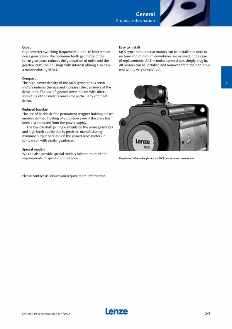
Easy to installMCS synchronous servo motors can be installed in next tono time and minimum downtimes are assured in the caseof replacements. All the motor connections simply plug in.All motors can be installed and removed from the non-driveend with a very simple tool.
Easy-to-install housing format on MCS synchronous servo motors
GeneralProduct information
1-6 Synchron-Servomotoren MCS en 4/2004
1
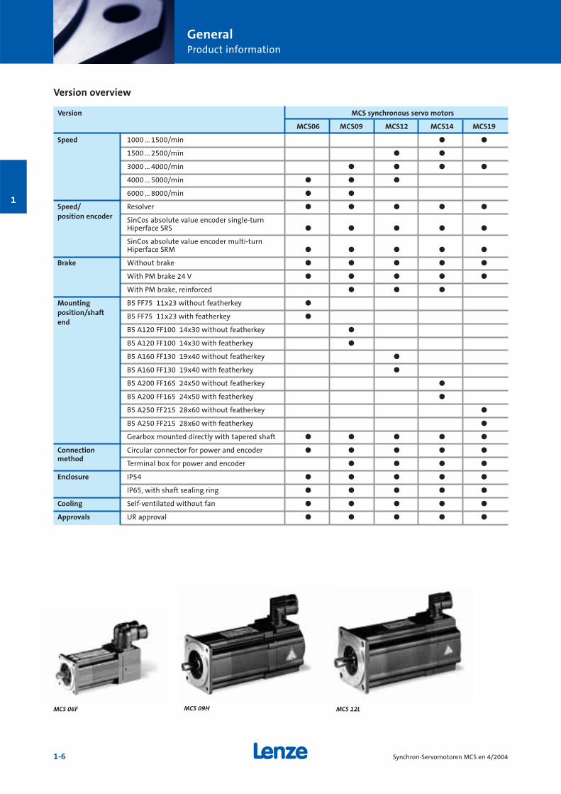
Version overview
Version MCS synchronous servo motors
MCS06 MCS09 MCS12 MCS14 MCS19
Speed 1000 … 1500/min ö ö
1500 … 2500/min ö ö
3000 … 4000/min ö ö ö ö
4000 … 5000/min ö ö ö
6000 … 8000/min ö ö
Speed/ Resolver ö ö ö ö ö
position encoder SinCos absolute value encoder single-turnHiperface SRS ö ö ö ö ö
SinCos absolute value encoder multi-turnHiperface SRM ö ö ö ö ö
Brake Without brake ö ö ö ö ö
With PM brake 24 V ö ö ö ö ö
With PM brake, reinforced ö ö ö
Mounting B5 FF75 11x23 without featherkey ö
position/shaft B5 FF75 11x23 with featherkey öend
B5 A120 FF100 14x30 without featherkey ö
B5 A120 FF100 14x30 with featherkey ö
B5 A160 FF130 19x40 without featherkey ö
B5 A160 FF130 19x40 with featherkey ö
B5 A200 FF165 24x50 without featherkey ö
B5 A200 FF165 24x50 with featherkey ö
B5 A250 FF215 28x60 without featherkey ö
B5 A250 FF215 28x60 with featherkey ö
Gearbox mounted directly with tapered shaft ö ö ö ö ö
Connection Circular connector for power and encoder ö ö ö ö ö
methodTerminal box for power and encoder ö ö ö ö
Enclosure IP54 ö ö ö ö ö
IP65, with shaft sealing ring ö ö ö ö ö
Cooling Self-ventilated without fan ö ö ö ö ö
Approvals UR approval ö ö ö ö ö
MCS 06F MCS 09H MCS 12L
GeneralProduct information
1-7Synchron-Servomotoren MCS en 4/2004
1
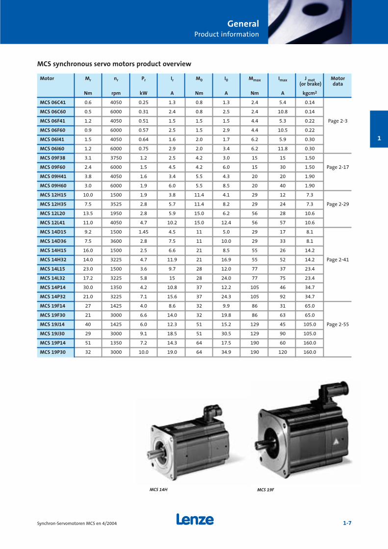
Motor Mr nr Pr Ir M0 I0 Mmax Imax J mot Motor (or brake) data
Nm rpm kW A Nm A Nm A kgcm2
MCS 06C41 0.6 4050 0.25 1.3 0.8 1.3 2.4 5.4 0.14
MCS 06C60 0.5 6000 0.31 2.4 0.8 2.5 2.4 10.8 0.14
MCS 06F41 1.2 4050 0.51 1.5 1.5 1.5 4.4 5.3 0.22 Page 2-3
MCS 06F60 0.9 6000 0.57 2.5 1.5 2.9 4.4 10.5 0.22
MCS 06I41 1.5 4050 0.64 1.6 2.0 1.7 6.2 5.9 0.30
MCS 06I60 1.2 6000 0.75 2.9 2.0 3.4 6.2 11.8 0.30
MCS 09F38 3.1 3750 1.2 2.5 4.2 3.0 15 15 1.50
MCS 09F60 2.4 6000 1.5 4.5 4.2 6.0 15 30 1.50 Page 2-17
MCS 09H41 3.8 4050 1.6 3.4 5.5 4.3 20 20 1.90
MCS 09H60 3.0 6000 1.9 6.0 5.5 8.5 20 40 1.90
MCS 12H15 10.0 1500 1.9 3.8 11.4 4.1 29 12 7.3
MCS 12H35 7.5 3525 2.8 5.7 11.4 8.2 29 24 7.3 Page 2-29
MCS 12L20 13.5 1950 2.8 5.9 15.0 6.2 56 28 10.6
MCS 12L41 11.0 4050 4.7 10.2 15.0 12.4 56 57 10.6
MCS 14D15 9.2 1500 1.45 4.5 11 5.0 29 17 8.1
MCS 14D36 7.5 3600 2.8 7.5 11 10.0 29 33 8.1
MCS 14H15 16.0 1500 2.5 6.6 21 8.5 55 26 14.2
MCS 14H32 14.0 3225 4.7 11.9 21 16.9 55 52 14.2 Page 2-41
MCS 14L15 23.0 1500 3.6 9.7 28 12.0 77 37 23.4
MCS 14L32 17.2 3225 5.8 15 28 24.0 77 75 23.4
MCS 14P14 30.0 1350 4.2 10.8 37 12.2 105 46 34.7
MCS 14P32 21.0 3225 7.1 15.6 37 24.3 105 92 34.7
MCS 19F14 27 1425 4.0 8.6 32 9.9 86 31 65.0
MCS 19F30 21 3000 6.6 14.0 32 19.8 86 63 65.0
MCS 19J14 40 1425 6.0 12.3 51 15.2 129 45 105.0 Page 2-55
MCS 19J30 29 3000 9.1 18.5 51 30.5 129 90 105.0
MCS 19P14 51 1350 7.2 14.3 64 17.5 190 60 160.0
MCS 19P30 32 3000 10.0 19.0 64 34.9 190 120 160.0
MCS synchronous servo motors product overview
MCS 14H MCS 19F

GeneralProduct information
1-8 Synchron-Servomotoren MCS en 4/2004
1
General data
Enclosure IP54/IP65
Thermal class Utilisation to temperature class F (VDE 0530) Insulation system (enamel-insulated wire) to thermal class H
UL conformance UR, recognised component
Insulation resistance Maximum voltage amplitude Û = 1.5 kVMaximum rate of voltage rise du/dt = 5 kV/µs
Vibration level N
Smooth running, run-out, concentricity (DIN 2955) N
Mechanical tolerance Diameter of shaft end d Ø11 to Ø28: k6,Diameter of centring flange: J6
Temperature monitoring Continuous temperature sensor (KTY 83-110), combined with 2 x PTC 150°C (KTY only on MCS 06)
Connection 2 circular connectors which can be rotated by 180° for a) motor and brakeb) resolver and temperature sensororterminal box (terminal box not possible on MCS 06)
Temperature range -20 to +40 °C without power derating (without brake)-10 to +40 °C without power derating (with brake)
Surface temperature Up to 140 °C
Installation height Up to 1000 m amsl without power derating
Demagnetising limit > 5 · Ir
Maximum torque > 4 · Mr
Angle sensor Resolver SinCos encoder
Design B5, (B14 on request)
Bearing Deep-groove ball bearing with high-temperature resistance grease, 2 sealing disks locating bearing on non-drive end
Shaft end With/without featherkey
Brake With or without permanent-magnet holding brake on non-drive end
Fan –
Colour Black, RAL 9005
GeneralProduct information
1-9Synchron-Servomotoren MCS en 4/2004
1
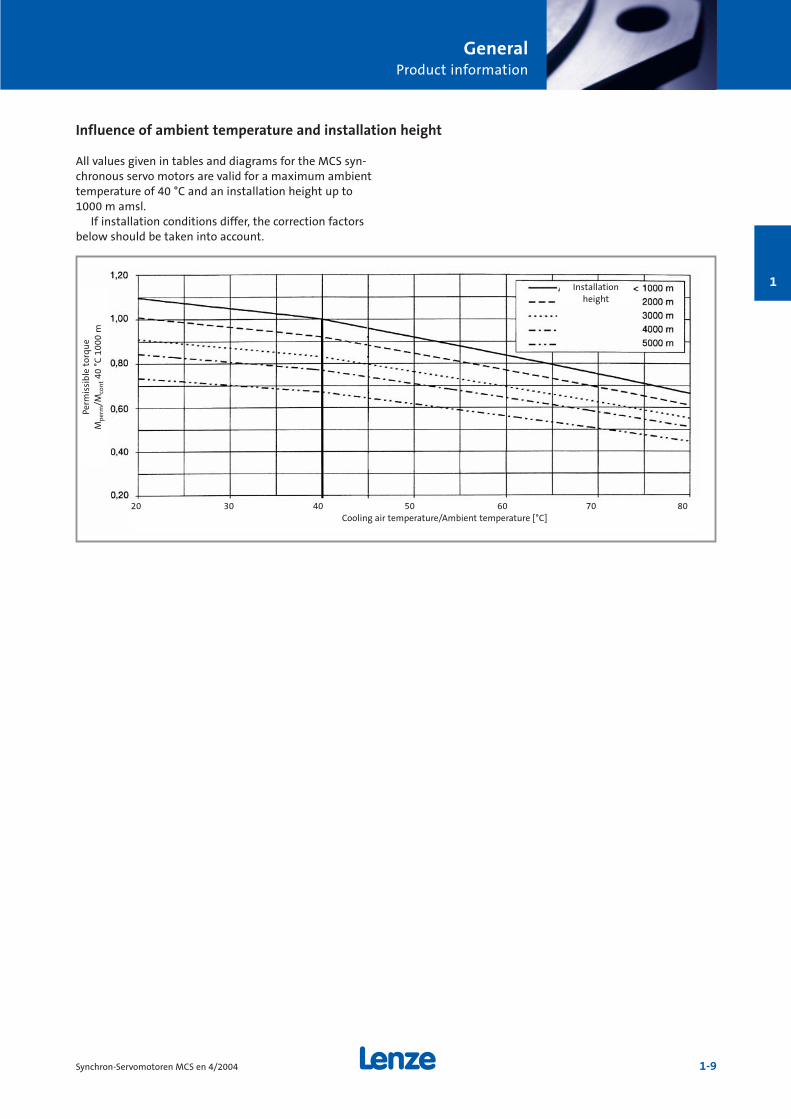
All values given in tables and diagrams for the MCS syn-chronous servo motors are valid for a maximum ambienttemperature of 40 °C and an installation height up to 1000 m amsl.
If installation conditions differ, the correction factorsbelow should be taken into account.
Influence of ambient temperature and installation height
Perm
issi
ble
tor
qu
eM
per
m/M
con
t40
°C
100
0 m
20 30 40 50 60 70 80Cooling air temperature/Ambient temperature [°C]
Installation height
GeneralDrive dimensioning
1-10 Synchron-Servomotoren MCS en 4/2004
1
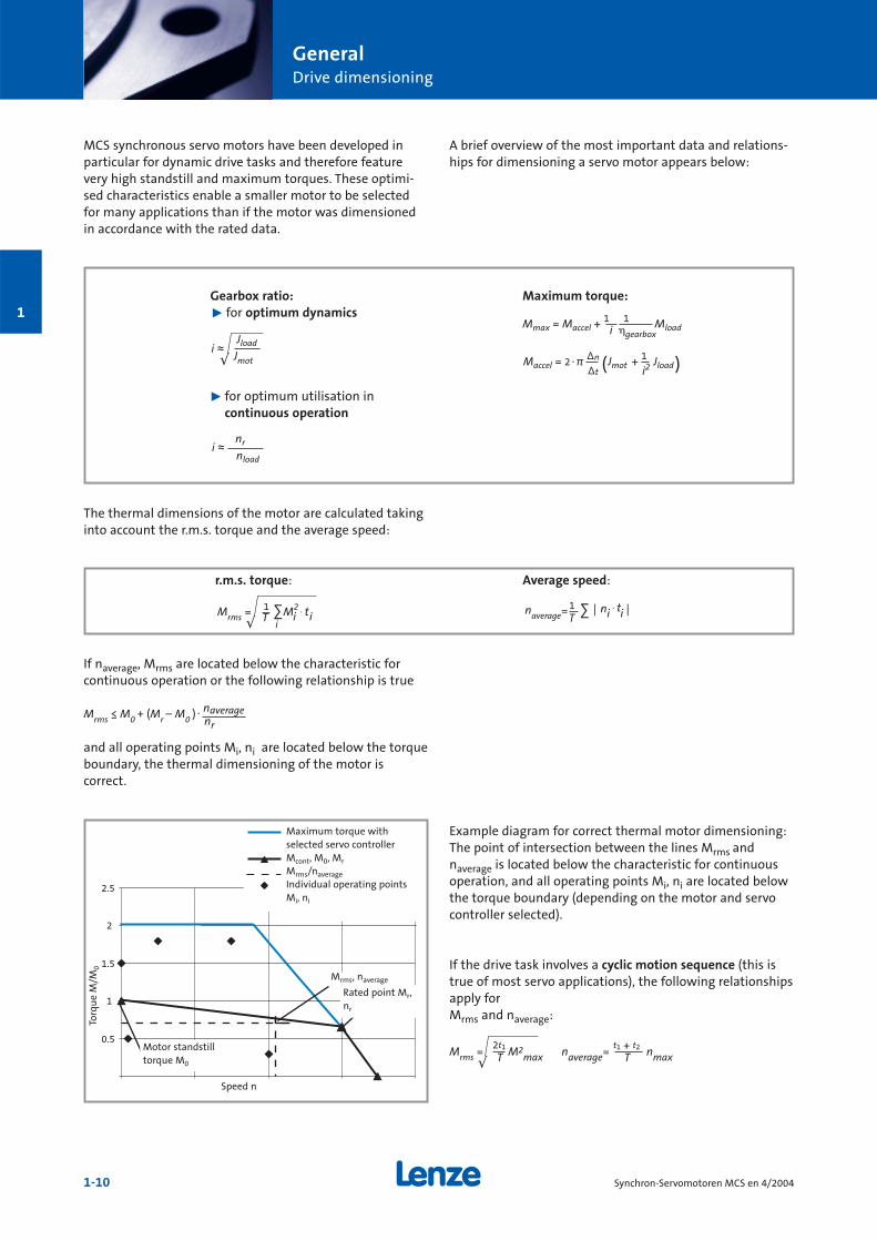
MCS synchronous servo motors have been developed inparticular for dynamic drive tasks and therefore featurevery high standstill and maximum torques. These optimi-sed characteristics enable a smaller motor to be selectedfor many applications than if the motor was dimensionedin accordance with the rated data.
A brief overview of the most important data and relations-hips for dimensioning a servo motor appears below:
Jloadi ≈√ Jmot
nri ≈nload
Mmax = Maccel +1 1 Mloadi gearbox
Maccel = 2yπ ∆n Jmot + 1 Jload
∆t i2( )
Gearbox ratio:˘ for optimum dynamics
˘ for optimum utilisation in continuous operation
Maximum torque:
The thermal dimensions of the motor are calculated takinginto account the r.m.s. torque and the average speed:
If naverage, Mrms are located below the characteristic for continuous operation or the following relationship is true
and all operating points Mi, ni are located below the torqueboundary, the thermal dimensioning of the motor is correct.
1 M2 . tMrms = i i√ T ∑i
naverage
Average speed:
. naverageMrms ≤ M0 + (Mr – M0 ) nr
0.5
1
1.5
2
2.5
Example diagram for correct thermal motor dimensioning:The point of intersection between the lines Mrms and naverage is located below the characteristic for continuous operation, and all operating points Mi, ni are located belowthe torque boundary (depending on the motor and servocontroller selected).
If the drive task involves a cyclic motion sequence (this istrue of most servo applications), the following relationshipsapply for Mrms and naverage:
2t1Mrms = M2max√ T
t1 + t2naverage= nmaxTMotor standstilltorque M0
Rated point Mr,nr
Mrms, naverage
Maximum torque with selected servo controllerMcont, M0, Mr
Mrms/naverage
Individual operating pointsMi, ni
Torq
ue
M/M
0
Speed n
1 n . t= | i i |T
∑
r.m.s. torque:
GeneralDrive dimensioning
1-11Synchron-Servomotoren MCS en 4/2004
1
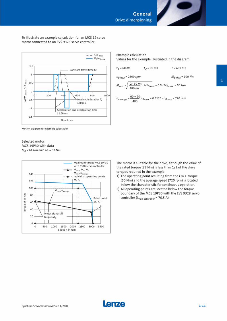
Example calculationValues for the example illustrated in the diagram:
t1 = 60 ms t2 = 90 ms T = 480 ms
nBmax = 2300 rpm MBmax = 100 Nm
Mrms = 2 · 60 ms · M2Bmax = 0.5 · MBmax = 50 Nm
√ 480 ms
naverage = 60 + 90 nBmax = 0.3125 · nBmax = 720 rpm480
The motor is suitable for the drive, although the value ofthe rated torque (32 Nm) is less than 1/3 of the drive torques required in the example:1) The operating point resulting from the r.m.s. torque
(50 Nm) and the average speed (720 rpm) is locatedbelow the characteristic for continuous operation.
2) All operating points are located below the torqueboundary of the MCS 19P30 with the EVS 9328 servocontroller (Imax controller = 70.5 A).
To illustrate an example calculation for an MCS 19 servomotor connected to an EVS 9328 servo controller:
-1.5
-1
-0.5
0
0.5
1
1.5
0 200 400 600 800 1000
0
20
40
60
80
100
120
140
0 500 1000 1500 2000 2500 3000 3500
Motion diagram for example calculation
Torq
ue
M in
Nm
Speed n in rpm
Motor standstilltorque M0
Mrms, naverage
Maximum torque MCS 19P30with 9328 servo controllerMcont, M0, Mr
Mrms/naverage
Individual operating pointsMi, ni
Rated pointMr, nr
n/n Bmax
M/M Bmax
Constant travel time t2
Load cycle duration T,480 ms
Acceleration and deceleration timet 1.60 ms
Time in ms
M/M
Bm
ax, n
/n B
max
Selected motor:MCS 19P30 with dataM0 = 64 Nm and Mr = 32 Nm
2-1Synchron-Servomotoren MCS en 4/2004
Technical data MCS synchronousservo motors
Synchronous servo motorsMCS 06
Rated data ______________ 2-3Servo controller assignment______ 2-4Torque characteristics _________ 2-8Brake assignment___________ 2-12Mechanical dimensions ________ 2-13Permissible shaft loads ________ 2-14
Synchronous servo motorsMCS 09
Rated data ______________ 2-17Servo controller assignment______ 2-18Torque characteristics_________ 2-22Brake assignment___________ 2-24Mechanical dimensions ________ 2-25Permissible shaft loads ________ 2-26
Synchronous servo motorsMCS 12
Rated data ______________ 2-29Servo controller assignment______ 2-30Torque characteristics_________ 2-34Brake assignment___________ 2-36Mechanical dimensions ________ 2-37Permissible shaft loads ________ 2-38
Synchronous servo motorsMCS 14
Rated data ______________ 2-41Servo controller assignment______ 2-42Torque characteristics_________ 2-46Brake assignment___________ 2-50Mechanical dimensions ________ 2-51Permissible shaft loads ________ 2-52
Synchronous servo motorsMCS 19
Rated data ______________ 2-55Servo controller assignment______ 2-56Torque characteristics_________ 2-60Brake assignment___________ 2-63Mechanical dimensions ________ 2-65Permissible shaft loads ________ 2-66
Options
Feedback systems___________ 2-68Temperature sensor__________ 2-70Terminal box _____________ 2-72
2

2-2 Synchron-Servomotoren MCS en 4/2004
2
Technical dataMCS 06 synchronous servo motors
2-3Synchron-Servomotoren MCS en 4/2004
2
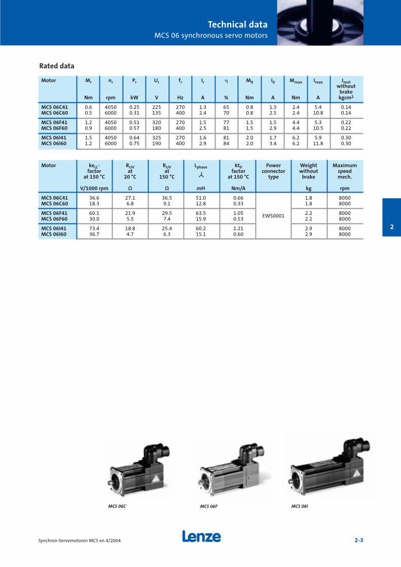
Rated data
MCS 06FMCS 06C MCS 06I
Motor keLL- RUV RUV Lphase kt0 Power Weight Maximumfactor at at factor connector without speed
at 150 °C 20 °C 150 °C at 150 °C type brake mech.
V/1000 rpm Ω Ω mH Nm/A kg rpm
MCS 06C41 36.6 27.1 36.5 51.0 0.66 1.8 8000MCS 06C60 18.3 6.8 9.1 12.8 0.33 1.8 8000
MCS 06F41 60.1 21.9 29.5 63.5 1.05 EWS0001 2.2 8000MCS 06F60 30.0 5.5 7.4 15.9 0.53 2.2 8000
MCS 06I41 73.4 18.8 25.4 60.2 1.21 2.9 8000MCS 06I60 36.7 4.7 6.3 15.1 0.60 2.9 8000
Motor Mr nr Pr Ur fr Ir M0 I0 Mmax Imax Jmotwithout
brakeNm rpm kW V Hz A % Nm A Nm A kgcm2
MCS 06C41 0.6 4050 0.25 225 270 1.3 65 0.8 1.3 2.4 5.4 0.14MCS 06C60 0.5 6000 0.31 135 400 2.4 70 0.8 2.5 2.4 10.8 0.14
MCS 06F41 1.2 4050 0.51 320 270 1.5 77 1.5 1.5 4.4 5.3 0.22MCS 06F60 0.9 6000 0.57 180 400 2.5 81 1.5 2.9 4.4 10.5 0.22
MCS 06I41 1.5 4050 0.64 325 270 1.6 81 2.0 1.7 6.2 5.9 0.30MCS 06I60 1.2 6000 0.75 190 400 2.9 84 2.0 3.4 6.2 11.8 0.30
Technical dataMCS 06 synchronous servo motors
2-4 Synchron-Servomotoren MCS en 4/2004
2
Servo controller assignment
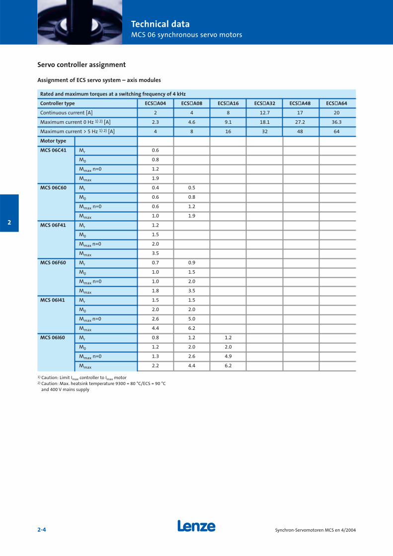
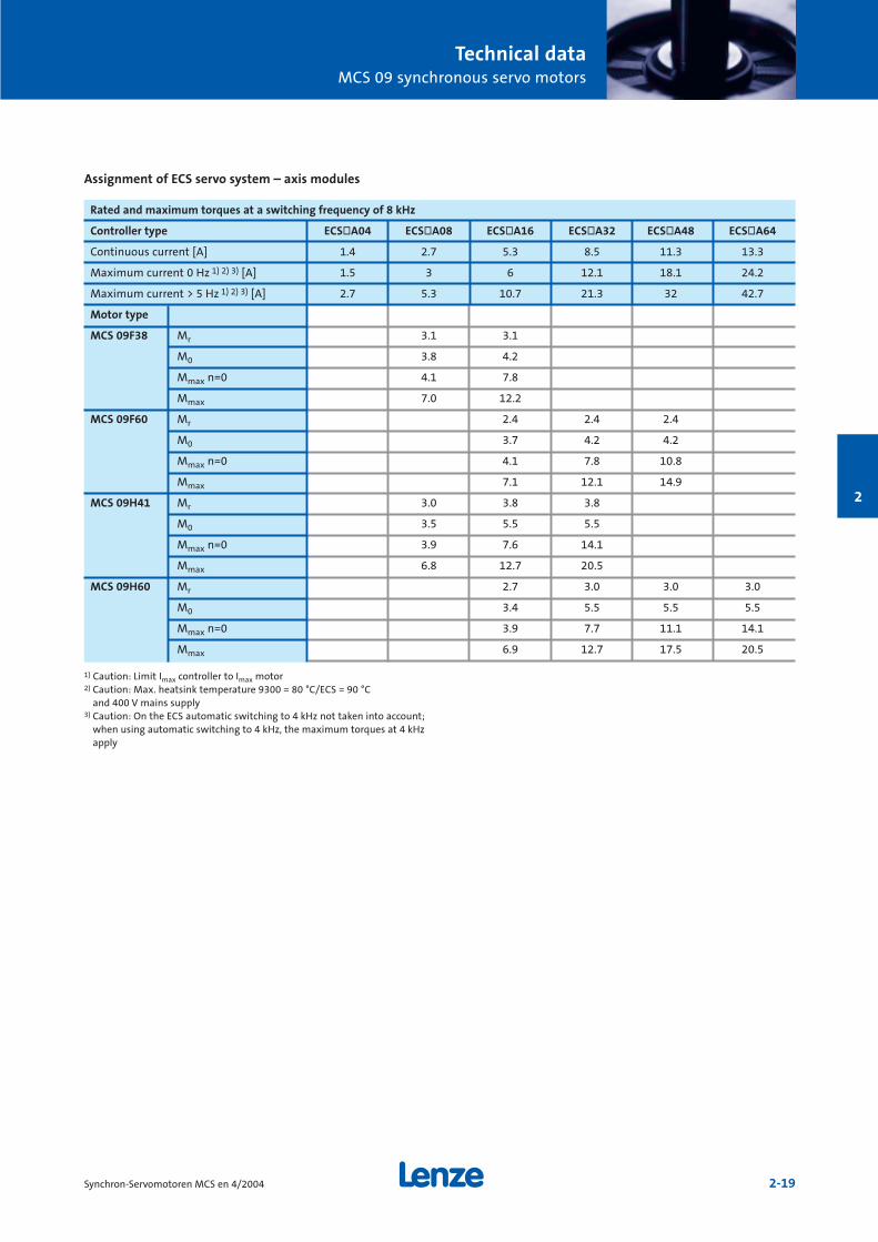
Assignment of ECS servo system – axis modules
Rated and maximum torques at a switching frequency of 4 kHz
Controller type ECSòA04 ECSòA08 ECSòA16 ECSòA32 ECSòA48 ECSòA64
Continuous current [A] 2 4 8 12.7 17 20
Maximum current 0 Hz 1) 2) [A] 2.3 4.6 9.1 18.1 27.2 36.3
Maximum current > 5 Hz 1) 2) [A] 4 8 16 32 48 64
Motor type
MCS 06C41 Mr 0.6
M0 0.8
Mmax n=0 1.2
Mmax 1.9
MCS 06C60 Mr 0.4 0.5
M0 0.6 0.8
Mmax n=0 0.6 1.2
Mmax 1.0 1.9
MCS 06F41 Mr 1.2
M0 1.5
Mmax n=0 2.0
Mmax 3.5
MCS 06F60 Mr 0.7 0.9
M0 1.0 1.5
Mmax n=0 1.0 2.0
Mmax 1.8 3.5
MCS 06I41 Mr 1.5 1.5
M0 2.0 2.0
Mmax n=0 2.6 5.0
Mmax 4.4 6.2
MCS 06I60 Mr 0.8 1.2 1.2
M0 1.2 2.0 2.0
Mmax n=0 1.3 2.6 4.9
Mmax 2.2 4.4 6.2
1) Caution: Limit Imax controller to Imax motor2) Caution: Max. heatsink temperature 9300 = 80 °C/ECS = 90 °C
and 400 V mains supply
Technical dataMCS 06 synchronous servo motors
2-5Synchron-Servomotoren MCS en 4/2004
2
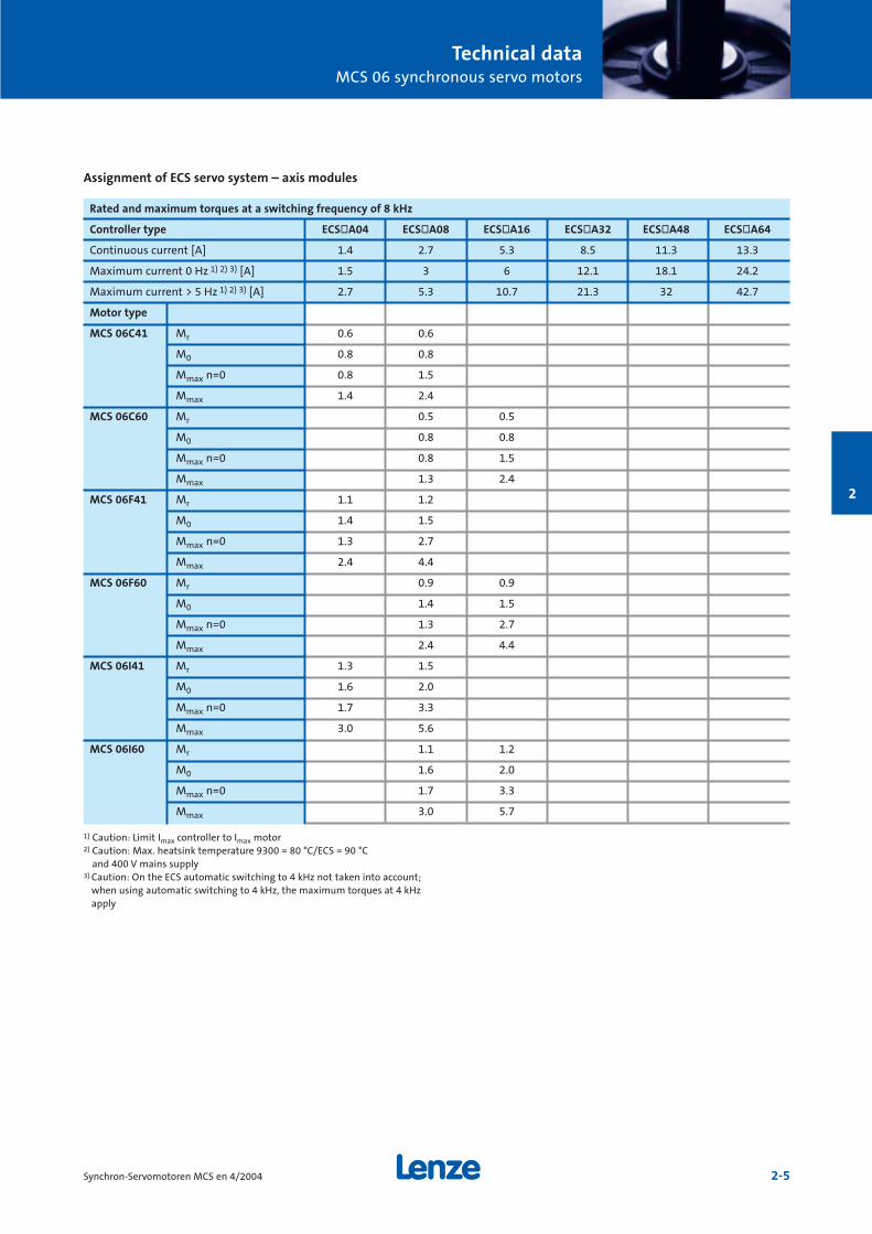
Rated and maximum torques at a switching frequency of 8 kHz
Controller type ECSòA04 ECSòA08 ECSòA16 ECSòA32 ECSòA48 ECSòA64
Continuous current [A] 1.4 2.7 5.3 8.5 11.3 13.3
Maximum current 0 Hz 1) 2) 3) [A] 1.5 3 6 12.1 18.1 24.2
Maximum current > 5 Hz 1) 2) 3) [A] 2.7 5.3 10.7 21.3 32 42.7
Motor type
MCS 06C41 Mr 0.6 0.6
M0 0.8 0.8
Mmax n=0 0.8 1.5
Mmax 1.4 2.4
MCS 06C60 Mr 0.5 0.5
M0 0.8 0.8
Mmax n=0 0.8 1.5
Mmax 1.3 2.4
MCS 06F41 Mr 1.1 1.2
M0 1.4 1.5
Mmax n=0 1.3 2.7
Mmax 2.4 4.4
MCS 06F60 Mr 0.9 0.9
M0 1.4 1.5
Mmax n=0 1.3 2.7
Mmax 2.4 4.4
MCS 06I41 Mr 1.3 1.5
M0 1.6 2.0
Mmax n=0 1.7 3.3
Mmax 3.0 5.6
MCS 06I60 Mr 1.1 1.2
M0 1.6 2.0
Mmax n=0 1.7 3.3
Mmax 3.0 5.7
1) Caution: Limit Imax controller to Imax motor2) Caution: Max. heatsink temperature 9300 = 80 °C/ECS = 90 °C
and 400 V mains supply3) Caution: On the ECS automatic switching to 4 kHz not taken into account;
when using automatic switching to 4 kHz, the maximum torques at 4 kHzapply
Assignment of ECS servo system – axis modules

Technical dataMCS 06 synchronous servo motors
2-6 Synchron-Servomotoren MCS en 4/2004
2
Rated and maximum torques at a switching frequency of 8 kHz
Controller type 9321 9322 9323 9324 9325 9326 9327 9328 9329 9330
Continuous current [A] 1.5 2.5 3.9 7 13 23.5 32 47 59 89
Maximum current 0 Hz 1) 2) [A] 2.3 3.8 5.9 10.5 19.5 23.5 32 47 52 80
Maximum current > 5 Hz 1) 2) [A] 2.3 3.8 5.9 10.5 19.5 35.25 48 70.5 88.5 133.5
Motor type
MCS 06C41 Mr 0.6 0.6 0.6
M04) 0.8 0.8 0.8
Mmax n=0 1.2 1.8 2.4
Mmax 1.2 1.8 2.4
MCS 06C60 Mr 0.5 0.5 0.5
M04) 0.8 0.8 0.8
Mmax n=0 1.0 1.5 2.4
Mmax 1.0 1.5 2.4
MCS 06F41 Mr 1.2 1.2 1.2
M04) 1.5 1.5 1.5
Mmax n=0 2.0 3.3 4.4
Mmax 2.0 3.3 4.4
MCS 06F60 Mr 0.9 0.9 0.9
M04) 1.3 1.5 1.5
Mmax n=0 1.7 2.6 4.4
Mmax 1.7 2.6 4.4
MCS 06I41 Mr 1.4 1.5 1.5
M04) 1.8 2.0 2.0
Mmax n=0 2.6 4.2 6.2
Mmax 2.6 4.2 6.2
MCS 06I60 Mr 1.0 1.2 1.2
M04) 1.5 2.0 2.0
Mmax n=0 2.1 3.3 5.6
Mmax 2.1 3.3 5.6
1) Caution: Limit Imax controller to Imax motor2) Caution: Max. heatsink temperature 9300 = 80 °C/ECS = 90 °C
and 400 V mains supply4) On the 9329 and 9330 at frequencies > 5 Hz, derating below 5 Hz
Servo controller assignment
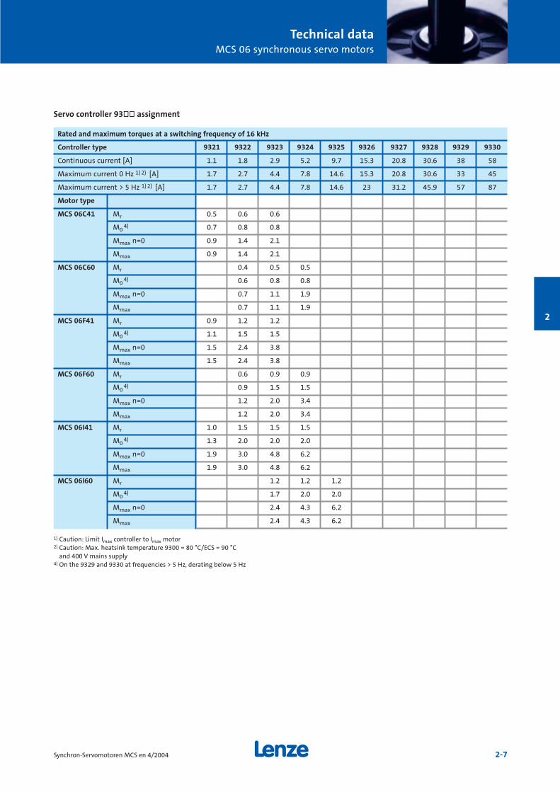
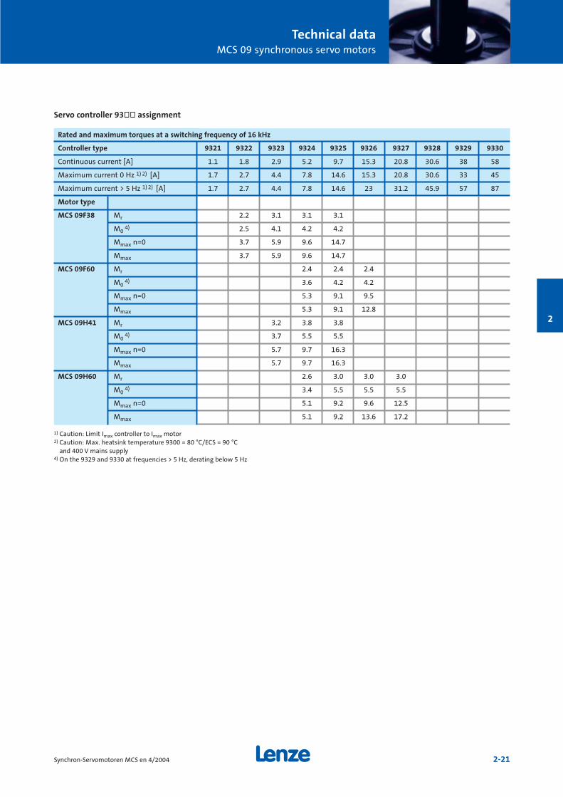
Servo controller 93òò assignment
Technical dataMCS 06 synchronous servo motors
2-7Synchron-Servomotoren MCS en 4/2004
2
Rated and maximum torques at a switching frequency of 16 kHz
Controller type 9321 9322 9323 9324 9325 9326 9327 9328 9329 9330
Continuous current [A] 1.1 1.8 2.9 5.2 9.7 15.3 20.8 30.6 38 58
Maximum current 0 Hz 1) 2) [A] 1.7 2.7 4.4 7.8 14.6 15.3 20.8 30.6 33 45
Maximum current > 5 Hz 1) 2) [A] 1.7 2.7 4.4 7.8 14.6 23 31.2 45.9 57 87
Motor type
MCS 06C41 Mr 0.5 0.6 0.6
M04) 0.7 0.8 0.8
Mmax n=0 0.9 1.4 2.1
Mmax 0.9 1.4 2.1
MCS 06C60 Mr 0.4 0.5 0.5
M04) 0.6 0.8 0.8
Mmax n=0 0.7 1.1 1.9
Mmax 0.7 1.1 1.9
MCS 06F41 Mr 0.9 1.2 1.2
M04) 1.1 1.5 1.5
Mmax n=0 1.5 2.4 3.8
Mmax 1.5 2.4 3.8
MCS 06F60 Mr 0.6 0.9 0.9
M04) 0.9 1.5 1.5
Mmax n=0 1.2 2.0 3.4
Mmax 1.2 2.0 3.4
MCS 06I41 Mr 1.0 1.5 1.5 1.5
M04) 1.3 2.0 2.0 2.0
Mmax n=0 1.9 3.0 4.8 6.2
Mmax 1.9 3.0 4.8 6.2
MCS 06I60 Mr 1.2 1.2 1.2
M04) 1.7 2.0 2.0
Mmax n=0 2.4 4.3 6.2
Mmax 2.4 4.3 6.2
1) Caution: Limit Imax controller to Imax motor2) Caution: Max. heatsink temperature 9300 = 80 °C/ECS = 90 °C
and 400 V mains supply4) On the 9329 and 9330 at frequencies > 5 Hz, derating below 5 Hz
Servo controller 93òò assignment
Technical dataMCS 06 synchronous servo motors
2-8 Synchron-Servomotoren MCS en 4/2004
2
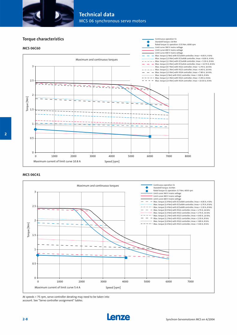
Torque characteristics
MCS 06C60
0
0.5
1
1.5
2
2.5
3
0 1000 2000 3000 4000 5000 6000 7000 8000
0
0.5
1
1.5
2
2.5
3
0 1000 2000 3000 4000 5000 6000 7000
MCS 06C41
Continuous operation S1
Standstill torque: 0.8 Nm
Rated torque S1 operation: 0.55 Nm; 6000 rpm
Limit curve 360 V mains voltage
Limit curve 400 V mains voltage
Limit curve 440 V mains voltage
Max. torque (1 Nm) with ECSxA04 controller; Imax = 4.00 A, 4 kHz
Max. torque (1.9 Nm) with ECSxA08 controller; Imax = 8.00 A, 4 kHz
Max. torque (1.3 Nm) with ECSxA08 controller; Imax = 5.30 A, 8 kHz
Max. torque (2.4 Nm) with ECSxA16 controller; Imax = 10.70 A, 8 kHz
Max. torque (0.7 Nm) with 9322 controller; Imax = 2.70 A, 16 kHz
Max. torque (1.1 Nm) with 9323 controller; Imax = 4.40 A, 16 kHz
Max. torque (1.9 Nm) with 9324 controller; Imax = 7.80 A, 16 kHz
Max. torque (1 Nm) with 9322 controller; Imax = 3.80 A, 8 kHz
Max. torque (1.5 Nm) with 9323 controller; Imax = 5.90 A, 8 kHz
Max. torque (2.4 Nm) with 9324 controller; Imax = 10.50 A, 8 kHz
Maximum and continuous torques
Torq
ue
[Nm
]
Speed [rpm]Maximum current of limit curve 10.8 A
Continuous operation S1
Standstill torque: 0.8 Nm
Rated torque S1 operation: 0.7 Nm; 4050 rpm
Limit curve 360 V mains voltage
Limit curve 400 V mains voltage
Limit curve 440 V mains voltage
Max. torque (1.9 Nm) with ECSxA04 controller; Imax = 4.00 A, 4 kHz
Max. torque (1.4 Nm) with ECSxA04 controller; Imax = 2.70 A, 8 kHz
Max. torque (2.4 Nm) with ECSxA08 controller; Imax = 5.30 A, 8 kHz
Max. torque (0.9 Nm) with 9321 controller; Imax = 1.70 A, 16 kHz
Max. torque (1.4 Nm) with 9322 controller; Imax = 2.70 A, 16 kHz
Max. torque (2.1 Nm) with 9323 controller; Imax = 4.40 A, 16 kHz
Max. torque (1.2 Nm) with 9321 controller; Imax = 2.30 A, 8 kHz
Max. torque (1.8 Nm) with 9322 controller; Imax = 3.80 A, 8 kHz
Max. torque (2.4 Nm) with 9323 controller; Imax = 5.40 A, 8 kHz
Maximum and continuous torques
Torq
ue
[Nm
]
Speed [rpm]Maximum current of limit curve 5.4 A
At speeds < 75 rpm, servo controller derating may need to be taken intoaccount. See "Servo controller assignment" tables.
Technical dataMC 06 synchronous servo motors
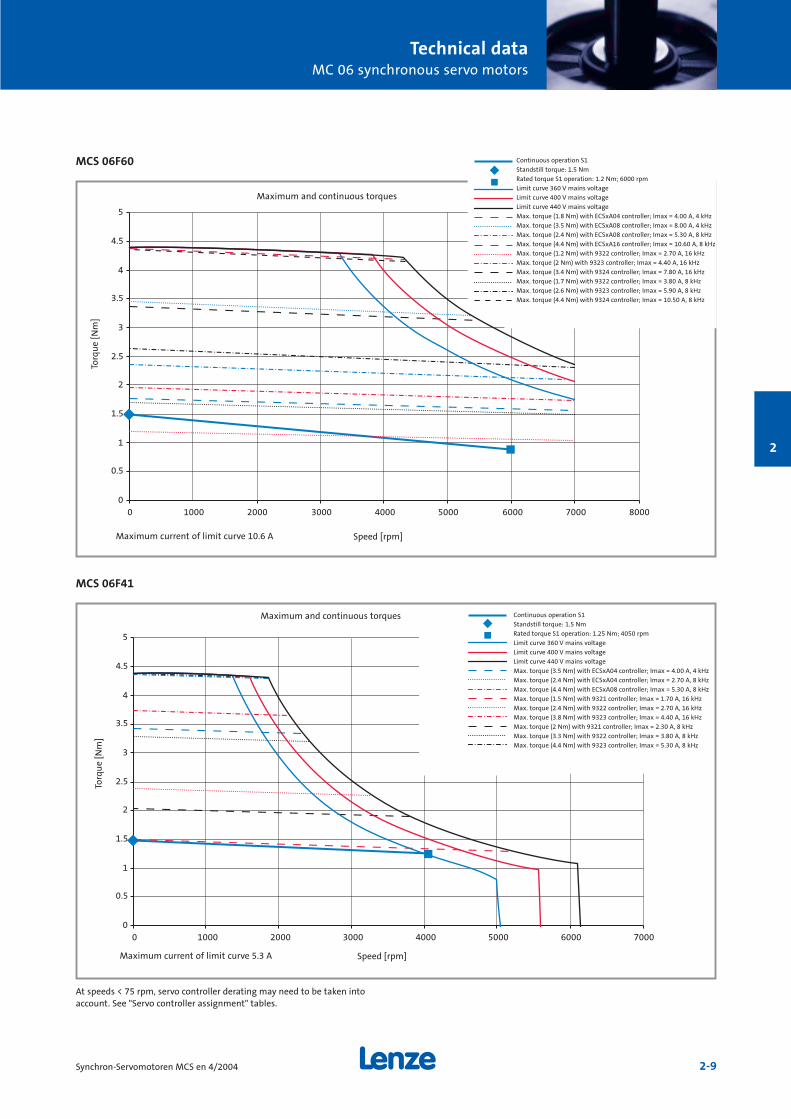
2-9Synchron-Servomotoren MCS en 4/2004
2
MCS 06F60
MCS 06F41
0
0.5
1
1.5
2
2.5
3
3.5
4
4.5
5
0 1000 2000 3000 4000 5000 6000 7000 8000
0
0.5
1
1.5
2
2.5
3
3.5
4
4.5
5
0 1000 2000 3000 4000 5000 6000 7000
Continuous operation S1
Standstill torque: 1.5 Nm
Rated torque S1 operation: 1.2 Nm; 6000 rpm
Limit curve 360 V mains voltage
Limit curve 400 V mains voltage
Limit curve 440 V mains voltage
Max. torque (1.8 Nm) with ECSxA04 controller; Imax = 4.00 A, 4 kHz
Max. torque (3.5 Nm) with ECSxA08 controller; Imax = 8.00 A, 4 kHz
Max. torque (2.4 Nm) with ECSxA08 controller; Imax = 5.30 A, 8 kHz
Max. torque (4.4 Nm) with ECSxA16 controller; Imax = 10.60 A, 8 kHz
Max. torque (1.2 Nm) with 9322 controller; Imax = 2.70 A, 16 kHz
Max. torque (2 Nm) with 9323 controller; Imax = 4.40 A, 16 kHz
Max. torque (3.4 Nm) with 9324 controller; Imax = 7.80 A, 16 kHz
Max. torque (1.7 Nm) with 9322 controller; Imax = 3.80 A, 8 kHz
Max. torque (2.6 Nm) with 9323 controller; Imax = 5.90 A, 8 kHz
Max. torque (4.4 Nm) with 9324 controller; Imax = 10.50 A, 8 kHz
Continuous operation S1
Standstill torque: 1.5 Nm
Rated torque S1 operation: 1.25 Nm; 4050 rpm
Limit curve 360 V mains voltage
Limit curve 400 V mains voltage
Limit curve 440 V mains voltage
Max. torque (3.5 Nm) with ECSxA04 controller; Imax = 4.00 A, 4 kHz
Max. torque (2.4 Nm) with ECSxA04 controller; Imax = 2.70 A, 8 kHz
Max. torque (4.4 Nm) with ECSxA08 controller; Imax = 5.30 A, 8 kHz
Max. torque (1.5 Nm) with 9321 controller; Imax = 1.70 A, 16 kHz
Max. torque (2.4 Nm) with 9322 controller; Imax = 2.70 A, 16 kHz
Max. torque (3.8 Nm) with 9323 controller; Imax = 4.40 A, 16 kHz
Max. torque (2 Nm) with 9321 controller; Imax = 2.30 A, 8 kHz
Max. torque (3.3 Nm) with 9322 controller; Imax = 3.80 A, 8 kHz
Max. torque (4.4 Nm) with 9323 controller; Imax = 5.30 A, 8 kHz
Maximum and continuous torques
Torq
ue
[Nm
]
Speed [rpm]Maximum current of limit curve 10.6 A
Maximum and continuous torques
Torq
ue
[Nm
]
Speed [rpm]Maximum current of limit curve 5.3 A
At speeds < 75 rpm, servo controller derating may need to be taken intoaccount. See "Servo controller assignment" tables.
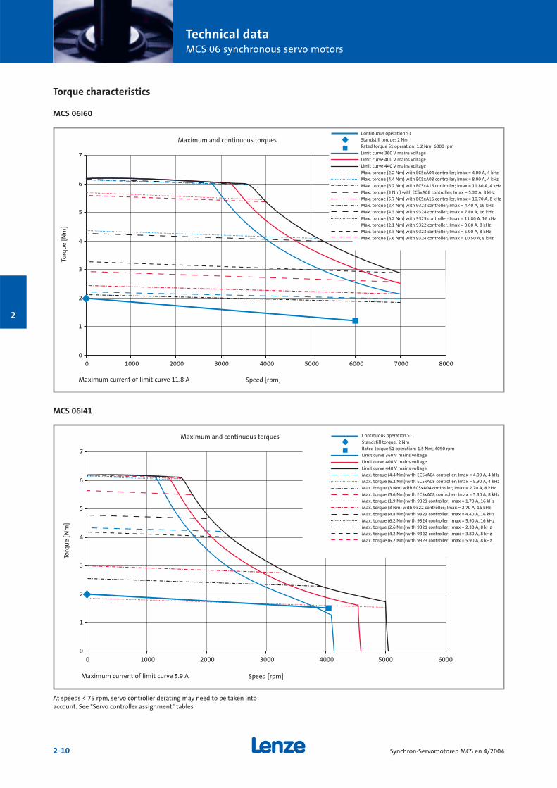
Technical dataMCS 06 synchronous servo motors
2-10 Synchron-Servomotoren MCS en 4/2004
2
Torque characteristics
MCS 06I60
MCS 06I41
0
1
2
3
4
5
6
7
0 1000 2000 3000 4000 5000 6000 7000 8000
0
1
2
3
4
5
6
7
0 1000 2000 3000 4000 5000 6000
Continuous operation S1
Standstill torque: 2 Nm
Rated torque S1 operation: 1.2 Nm; 6000 rpm
Limit curve 360 V mains voltage
Limit curve 400 V mains voltage
Limit curve 440 V mains voltage
Max. torque (2.2 Nm) with ECSxA04 controller; Imax = 4.00 A, 4 kHz
Max. torque (4.4 Nm) with ECSxA08 controller; Imax = 8.00 A, 4 kHz
Max. torque (6.2 Nm) with ECSxA16 controller; Imax = 11.80 A, 4 kHz
Max. torque (3 Nm) with ECSxA08 controller; Imax = 5.30 A, 8 kHz
Max. torque (5.7 Nm) with ECSxA16 controller; Imax = 10.70 A, 8 kHz
Max. torque (2.4 Nm) with 9323 controller; Imax = 4.40 A, 16 kHz
Max. torque (4.3 Nm) with 9324 controller; Imax = 7.80 A, 16 kHz
Max. torque (6.2 Nm) with 9325 controller; Imax = 11.80 A, 16 kHz
Max. torque (2.1 Nm) with 9322 controller; Imax = 3.80 A, 8 kHz
Max. torque (3.3 Nm) with 9323 controller; Imax = 5.90 A, 8 kHz
Max. torque (5.6 Nm) with 9324 controller; Imax = 10.50 A, 8 kHz
Maximum and continuous torques
Torq
ue
[Nm
]
Speed [rpm]Maximum current of limit curve 11.8 A
Continuous operation S1
Standstill torque: 2 Nm
Rated torque S1 operation: 1.5 Nm; 4050 rpm
Limit curve 360 V mains voltage
Limit curve 400 V mains voltage
Limit curve 440 V mains voltage
Max. torque (4.4 Nm) with ECSxA04 controller; Imax = 4.00 A, 4 kHz
Max. torque (6.2 Nm) with ECSxA08 controller; Imax = 5.90 A, 4 kHz
Max. torque (3 Nm) with ECSxA04 controller; Imax = 2.70 A, 8 kHz
Max. torque (5.6 Nm) with ECSxA08 controller; Imax = 5.30 A, 8 kHz
Max. torque (1.9 Nm) with 9321 controller; Imax = 1.70 A, 16 kHz
Max. torque (3 Nm) with 9322 controller; Imax = 2.70 A, 16 kHz
Max. torque (4.8 Nm) with 9323 controller; Imax = 4.40 A, 16 kHz
Max. torque (6.2 Nm) with 9324 controller; Imax = 5.90 A, 16 kHz
Max. torque (2.6 Nm) with 9321 controller; Imax = 2.30 A, 8 kHz
Max. torque (4.2 Nm) with 9322 controller; Imax = 3.80 A, 8 kHz
Max. torque (6.2 Nm) with 9323 controller; Imax = 5.90 A, 8 kHz
Maximum and continuous torques
Torq
ue
[Nm
]
Speed [rpm]Maximum current of limit curve 5.9 A
At speeds < 75 rpm, servo controller derating may need to be taken intoaccount. See "Servo controller assignment" tables.

2-11Synchron-Servomotoren MCS en 4/2004
2
Technical dataMCS 06 synchronous servo motors
2-12 Synchron-Servomotoren MCS en 4/2004
2
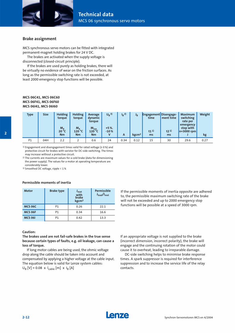
Brake assignment
MCS synchronous servo motors can be fitted with integratedpermanent-magnet holding brakes for 24 V DC.
The brakes are activated when the supply voltage is disconnected (closed-circuit principle).
If the brakes are used purely as holding brakes, there willbe virtually no evidence of wear on the friction surfaces. Aslong as the permissible switching rate is not exceeded, atleast 2000 emergency stop functions will be possible.
MCS 06C41, MCS 06C60MCS 06F41, MCS 06F60MCS 06I41, MCS 06I60
1) Engagement and disengagement times valid for rated voltage (± 0 %) andprotective circuit for brakes with varistor for DC-side switching. The timesmay increase without a protective circuit.
2) The currents are maximum values for a cold brake (data for dimensioningthe power supply). The values for a motor at operating temperature areconsiderably lower.
3) Smoothed DC voltage, ripple < 1 %
If the permissible moments of inertia opposite are adheredto, the permissible maximum switching rate of the brakewill not be exceeded and up to 2000 emergency stop functions will be possible at a speed of 3000 rpm.
Motor Brake type Jmot Permissiblewith Jload/Jmotbrakekgcm2
MCS 06C P1 0.26 22.1
MCS 06F P1 0.34 16.6
MCS 06I P1 0.42 13.3
Permissible moments of inertia
Type Size Holding Holding Average UB3) IB
2) JB Engagement Disengage- Maximum Weighttorque torque dynamic time ment time switching
torque rate peremergency
M4 M4 M1m +5 %. stop with 20 °C 120 °C 120 °C -10 % t1 1) t2 1) n=3000 rpmNm Nm Nm V A kgcm2 ms ms J kg
P1 04H 2.2 2 0.6 24 0.34 0.12 15 30 29.6 0.27
Caution:The brakes used are not fail-safe brakes in the true sensebecause certain types of faults, e.g. oil leakage, can cause aloss of torque.
If long motor cables are being used, the ohmic voltagedrop along the cable should be taken into account and compensated by applying a higher voltage at the cable input.The equation below is valid for Lenze system cables: UB [V] = 0.08 x lcable [m] x IB [A]
If an appropriate voltage is not supplied to the brake (incorrect dimension, incorrect polarity), the brake willengage and the continuing rotation of the motor couldcause it to overheat, leading to irreparable damage.
DC-side switching helps to minimise brake responsetimes. A spark suppressor is required for interference suppression and to increase the service life of the relaycontacts.
Technical dataMCS 06 synchronous servo motors
2-13Synchron-Servomotoren MCS en 4/2004
2
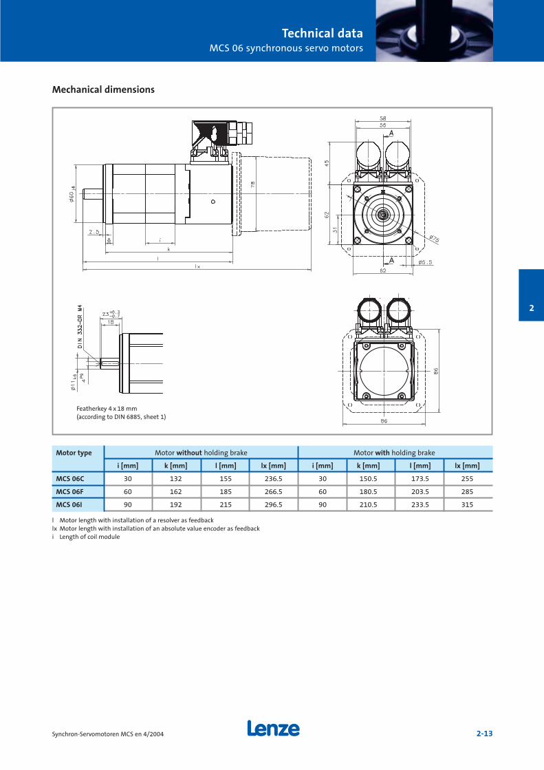
Mechanical dimensions
l Motor length with installation of a resolver as feedbacklx Motor length with installation of an absolute value encoder as feedbacki Length of coil module
Motor type Motor without holding brake Motor with holding brake
i [mm] k [mm] l [mm] lx [mm] i [mm] k [mm] l [mm] lx [mm]
MCS 06C 30 132 155 236.5 30 150.5 173.5 255
MCS 06F 60 162 185 266.5 60 180.5 203.5 285
MCS 06I 90 192 215 296.5 90 210.5 233.5 315
Featherkey 4 x 18 mm(according to DIN 6885, sheet 1)
Technical dataMCS 06 synchronous servo motors
2-14 Synchron-Servomotoren MCS en 4/2004
2
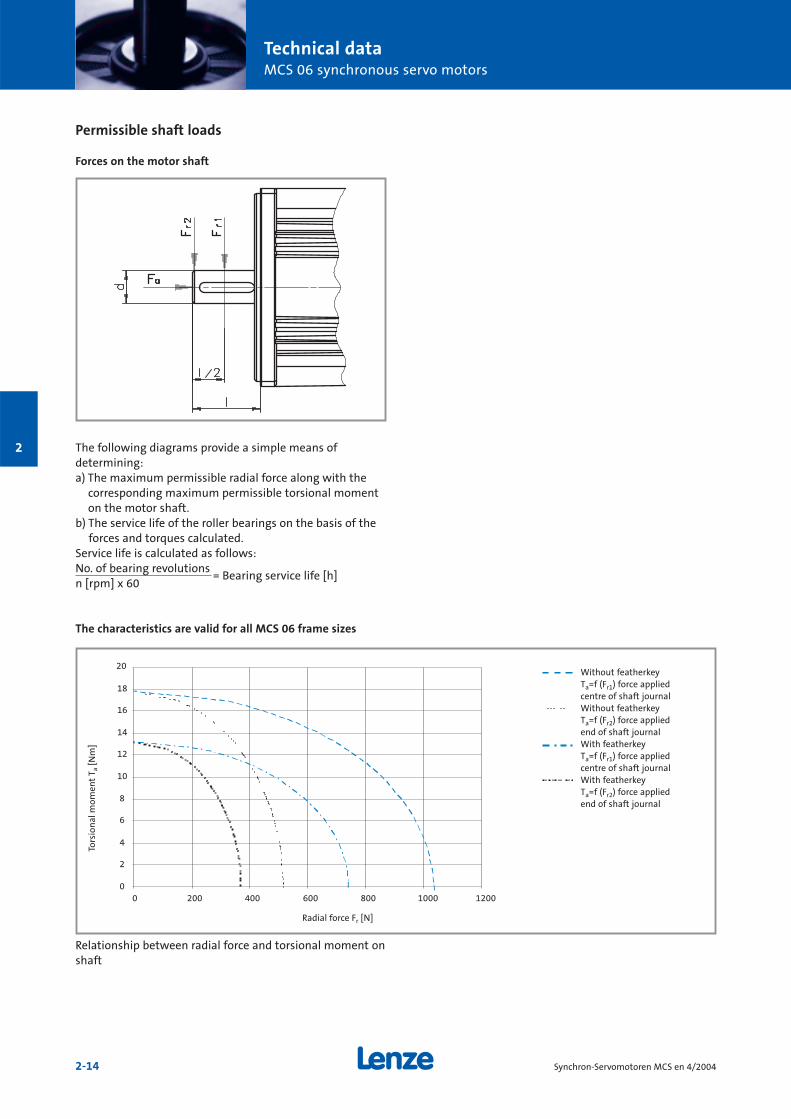
Permissible shaft loads
Forces on the motor shaft
The following diagrams provide a simple means of determining:a) The maximum permissible radial force along with the
corresponding maximum permissible torsional momenton the motor shaft.
b) The service life of the roller bearings on the basis of theforces and torques calculated.
Service life is calculated as follows:No. of bearing revolutions
= Bearing service life [h]n [rpm] x 60
The characteristics are valid for all MCS 06 frame sizes
0
2
4
6
8
10
12
14
16
18
20
0 200 400 600 800 1000 1200
Relationship between radial force and torsional moment onshaft
Without featherkeyTa=f (Fr1) force appliedcentre of shaft journalWithout featherkeyTa=f (Fr2) force appliedend of shaft journalWith featherkeyTa=f (Fr1) force appliedcentre of shaft journalWith featherkeyTa=f (Fr2) force appliedend of shaft journal
Radial force Fr [N]
Tors
ion
al m
omen
tT a
[Nm
]
Technical dataMCS 06 synchronous servo motors
2-15Synchron-Servomotoren MCS en 4/2004
2
0
100
200
300
400
500
600
700
800
900
1000
-400 -300 -200 -100 0 100 200 300
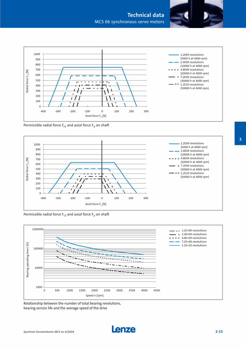
Permissible radial force Fr1 and axial force Fa on shaft
0
100
200
300
400
500
600
700
800
900
1000
-400 -300 -200 -100 0 100 200 300
Permissible radial force Fr2 and axial force Fa on shaft
1000
10000
100000
1000000
0 500 1000 1500 2000 2500 3000 3500 4000 4500
Relationship between the number of total bearing revolutions,bearing service life and the average speed of the drive
1.2E09 revolutions(5000 h at 4000 rpm)2.4E09 revolutions(10000 h at 4000 rpm)4.8E09 revolutions(20000 h at 4000 rpm)7.2E09 revolutions(30000 h at 4000 rpm)1.2E10 revolutions(50000 h at 4000 rpm)
1.2E09 revolutions(5000 h at 4000 rpm)2.4E09 revolutions(10000 h at 4000 rpm)4.8E09 revolutions(20000 h at 4000 rpm)7.2E09 revolutions(30000 h at 4000 rpm)1.2E10 revolutions(50000 h at 4000 rpm)
1.2E+09 revolutions2.4E+09 revolutions4.8E+09 revolutions7.2E+09 revolutions1.2E+10 revolutions
Axial force Fa [N]
Rad
ial f
orce
Fr1
[N]
Axial force Fa [N]
Rad
ial f
orce
Fr2
[N]
Speed n [rpm]
Bea
rin
g op
erat
ing
tim
e t
[h]

2-16 Synchron-Servomotoren MCS en 4/2004
2

Technical dataMCS 09 synchronous servo motors
2-17Synchron-Servomotoren MCS en 4/2004
2
Rated data
MCS 09F MCS 09H
Motor keLL- RUV RUV Lphase kt0 Power Weight Maximumfactor at at factor connector without speed
at 150°C 20°C 150°C at 150°C type brake mech.
V/1000 rpm Ω Ω mH Nm/A kg rpm
MCS 09F38 79.8 5.2 7.0 24.6 1.40 5.2 7000MCS 09F60 39.9 1.3 1.8 6.2 0.70 5.2 7000
MCS 09H41 75.7 3.2 4.3 16.1 1.29EWS0001
6.1 7000MCS 09H60 37.8 0.8 1.1 4.0 0.64 6.1 7000
Motor Mr nr Pr Ur fr Ir M0 I0 Mmax Imax Jmotwithoutbrake
Nm rpm kW V Hz A % Nm A Nm A kgcm2
MCS 09F38 3.1 3750 1.2 330 250 2.5 90 4.2 3.0 15 15 1.50MCS 09F60 2.4 6000 1.5 230 400 4.5 90 4.2 6.0 15 30 1.50
MCS 09H41 3.8 4050 1.6 300 270 3.4 91 5.5 4.3 20 20 1.90MCS 09H60 3.0 6000 1.9 190 400 6.0 91 5.5 8.5 20 40 1.90

Technical dataMCS 09 synchronous servo motors
2-18 Synchron-Servomotoren MCS en 4/2004
2
Servo controller assignment
Assignment of ECS servo system – axis modules
Rated and maximum torques at a switching frequency of 4 kHz
Controller type ECSòA04 ECSòA08 ECSòA16 ECSòA32 ECSòA48 ECSòA64
Continuous current [A] 2 4 8 12.7 17 20
Maximum current 0 Hz 1) 2) [A] 2.3 4.6 9.1 18.1 27.2 36.3
Maximum current > 5 Hz 1) 2) [A] 4 8 16 32 48 64
Motor type
MCS 09F38 Mr 2.5 3.1 3.1
M0 2.8 4.2 4.2
Mmax n=0 3.2 6.2 10.8
Mmax 5.5 9.8 14.9
MCS 09F60 Mr 2.1 2.4 2.4
M0 2.8 4.2 4.2
Mmax n=0 3.2 6.1 10.8
Mmax 5.5 9.8 14.9
MCS 09H41 Mr 3.8 3.8
M0 5.2 5.5
Mmax n=0 5.9 11.1
Mmax 9.9 17.5
MCS 09H60 Mr 3.0 3.0 3.0
M0 5.2 5.5 5.5
Mmax n=0 5.9 11.1 15.5
Mmax 10.0 17.5 20.5
1) Caution: Limit Imax controller to Imax motor2) Caution: Max. heatsink temperature 9300 = 80 °C/ECS = 90 °C
and 400 V mains supply
Technical dataMCS 09 synchronous servo motors
2-19Synchron-Servomotoren MCS en 4/2004
2
Rated and maximum torques at a switching frequency of 8 kHz
Controller type ECSòA04 ECSòA08 ECSòA16 ECSòA32 ECSòA48 ECSòA64
Continuous current [A] 1.4 2.7 5.3 8.5 11.3 13.3
Maximum current 0 Hz 1) 2) 3) [A] 1.5 3 6 12.1 18.1 24.2
Maximum current > 5 Hz 1) 2) 3) [A] 2.7 5.3 10.7 21.3 32 42.7
Motor type
MCS 09F38 Mr 3.1 3.1
M0 3.8 4.2
Mmax n=0 4.1 7.8
Mmax 7.0 12.2
MCS 09F60 Mr 2.4 2.4 2.4
M0 3.7 4.2 4.2
Mmax n=0 4.1 7.8 10.8
Mmax 7.1 12.1 14.9
MCS 09H41 Mr 3.0 3.8 3.8
M0 3.5 5.5 5.5
Mmax n=0 3.9 7.6 14.1
Mmax 6.8 12.7 20.5
MCS 09H60 Mr 2.7 3.0 3.0 3.0
M0 3.4 5.5 5.5 5.5
Mmax n=0 3.9 7.7 11.1 14.1
Mmax 6.9 12.7 17.5 20.5
1) Caution: Limit Imax controller to Imax motor2) Caution: Max. heatsink temperature 9300 = 80 °C/ECS = 90 °C
and 400 V mains supply3) Caution: On the ECS automatic switching to 4 kHz not taken into account;
when using automatic switching to 4 kHz, the maximum torques at 4 kHzapply
Assignment of ECS servo system – axis modules

Technical dataMCS 09 synchronous servo motors
2-20 Synchron-Servomotoren MCS en 4/2004
2
Rated and maximum torques at a switching frequency of 8 kHz
Controller type 9321 9322 9323 9324 9325 9326 9327 9328 9329 9330
Continuous current [A] 1.5 2.5 3.9 7 13 23.5 32 47 59 89
Maximum current 0 Hz 1) 2) [A] 2.3 3.8 5.9 10.5 19.5 23.5 32 47 52 80
Maximum current > 5 Hz 1) 2) [A] 2.3 3.8 5.9 10.5 19.5 35.25 48 70.5 88.5 133.5
Motor type
MCS 09F38 Mr 3.1 3.1 3.1
M04) 3.5 4.2 4.2
Mmax n=0 5.2 7.7 12.0
Mmax 5.2 7.7 12.0
MCS 09F60 Mr 2.1 2.4 2.4
M04) 2.7 4.2 4.2
Mmax n=0 4.1 6.9 11.4
Mmax 4.1 6.9 11.4
MCS 09H41 Mr 2.8 3.8 3.8 3.8
M04) 3.2 5.0 5.5 5.5
Mmax n=0 4.9 7.5 12.5 20.1
Mmax 4.9 7.5 12.5 20.1
MCS 09H60 Mr 3.0 3.0 3.0
M04) 4.5 5.5 5.5
Mmax n=0 6.8 11.8 13.8
Mmax 6.8 11.8 18.8
1) Caution: Limit Imax controller to Imax motor2) Caution: Max. heatsink temperature 9300 = 80 °C/ECS = 90 °C
and 400 V mains supply4) On the 9329 and 9330 at frequencies > 5 Hz, derating below 5 Hz
Servo controller assignment
Servo controller 93òò assignment
Technical dataMCS 09 synchronous servo motors
2-21Synchron-Servomotoren MCS en 4/2004
2
Rated and maximum torques at a switching frequency of 16 kHz
Controller type 9321 9322 9323 9324 9325 9326 9327 9328 9329 9330
Continuous current [A] 1.1 1.8 2.9 5.2 9.7 15.3 20.8 30.6 38 58
Maximum current 0 Hz 1) 2) [A] 1.7 2.7 4.4 7.8 14.6 15.3 20.8 30.6 33 45
Maximum current > 5 Hz 1) 2) [A] 1.7 2.7 4.4 7.8 14.6 23 31.2 45.9 57 87
Motor type
MCS 09F38 Mr 2.2 3.1 3.1 3.1
M04) 2.5 4.1 4.2 4.2
Mmax n=0 3.7 5.9 9.6 14.7
Mmax 3.7 5.9 9.6 14.7
MCS 09F60 Mr 2.4 2.4 2.4
M04) 3.6 4.2 4.2
Mmax n=0 5.3 9.1 9.5
Mmax 5.3 9.1 12.8
MCS 09H41 Mr 3.2 3.8 3.8
M04) 3.7 5.5 5.5
Mmax n=0 5.7 9.7 16.3
Mmax 5.7 9.7 16.3
MCS 09H60 Mr 2.6 3.0 3.0 3.0
M04) 3.4 5.5 5.5 5.5
Mmax n=0 5.1 9.2 9.6 12.5
Mmax 5.1 9.2 13.6 17.2
1) Caution: Limit Imax controller to Imax motor2) Caution: Max. heatsink temperature 9300 = 80 °C/ECS = 90 °C
and 400 V mains supply4) On the 9329 and 9330 at frequencies > 5 Hz, derating below 5 Hz
Servo controller 93òò assignment
Technical dataMCS 09 synchronous servo motors
2-22 Synchron-Servomotoren MCS en 4/2004
2
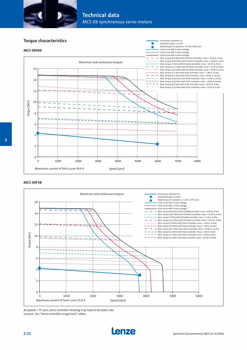
Torque characteristics
MCS 09F60
0
2
4
6
8
10
12
14
16
0 1000 2000 3000 4000 5000 6000 7000 8000
0
2
4
6
8
10
12
14
16
0 1000 2000 3000 4000 5000 6000
MCS 09F38
Continuous operation S1
Standstill torque: 4.2 Nm
Rated torque S1 operation: 2.4 Nm; 6000 rpm
Limit curve 360 V mains voltage
Limit curve 400 V mains voltage
Limit curve 440 V mains voltage
Max. torque (9.8 Nm) with ECSxA16 controller; Imax = 16.00 A, 4 kHz
Max. torque (14.9 Nm) with ECSxA32 controller; Imax = 30.00 A, 4 kHz
Max. torque (7 Nm) with ECSxA16 controller; Imax = 10.70 A, 8 kHz
Max. torque (12.1 Nm) with ECSxA32 controller; Imax = 21.30 A, 8 kHz
Max. torque (14.9 Nm) with ECSxA48 controller; Imax = 30.00 A, 8 kHz
Max. torque (5.3 Nm) with 9324 controller; Imax = 7.80 A, 16 kHz
Max. torque (9.1 Nm) with 9325 controller; Imax = 14.60 A, 16 kHz
Max. torque (12.8 Nm) with 9326 controller; Imax = 23.00 A, 16 kHz
Max. torque (14.9 Nm) with 9327 controller; Imax = 30.00 A, 16 kHz
Max. torque (6.9 Nm) with 9324 controller; Imax = 10.50 A, 8 kHz
Max. torque (11.4 Nm) with 9325 controller; Imax = 19.50 A, 8 kHz
Maximum and continuous torques
Torq
ue
[Nm
]
Speed [rpm]Maximum current of limit curve 30.0 A
Continuous operation S1
Standstill torque: 4.2 Nm
Rated torque S1 operation: 3.1 Nm; 3750 rpm
Limit curve 360 V mains voltage
Limit curve 400 V mains voltage
Limit curve 440 V mains voltage
Max. torque (9.8 Nm) with ECSxA08 controller; Imax = 8.00 A, 4 kHz
Max. torque (14.9 Nm) with ECSxA16 controller; Imax = 15.00 A, 4 kHz
Max. torque (7 Nm) with ECSxA08 controller; Imax = 5.30 A, 8 kHz
Max. torque (12.2 Nm) with ECSxA16 controller; Imax = 10.70 A, 8 kHz
Max. torque (5.9 Nm) with 9323 controller; Imax = 4.40 A, 16 kHz
Max. torque (9.6 Nm) with 9324 controller; Imax = 7.80 A, 16 kHz
Max. torque (14.7 Nm) with 9325 controller; Imax = 14.60 A, 16 kHz
Max. torque (5.2 Nm) with 9322 controller; Imax = 3.80 A, 8 kHz
Max. torque (7.7 Nm) with 9323 controller; Imax = 5.90 A, 8 kHz
Max. torque (12 Nm) with 9324 controller; Imax = 10.50 A, 8 kHz
Maximum and continuous torques
Torq
ue
[Nm
]
Speed [rpm]Maximum current of limit curve 15.0 A
At speeds < 75 rpm, servo controller derating may need to be taken intoaccount. See "Servo controller assignment" tables.
Technical dataMCS 09 synchronous servo motors
2-23Synchron-Servomotoren MCS en 4/2004
2
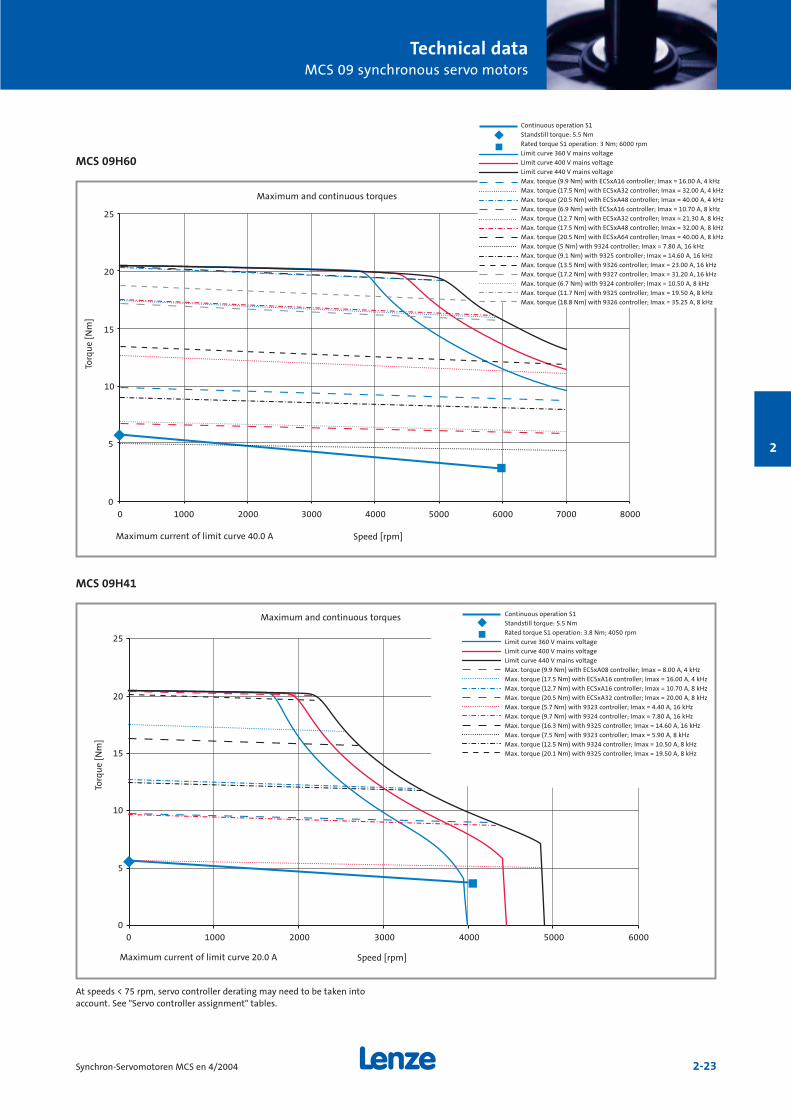
MCS 09H60
MCS 09H41
0
5
10
15
20
25
0 1000 2000 3000 4000 5000 6000 7000 8000
0
5
10
15
20
25
0 1000 2000 3000 4000 5000 6000
Continuous operation S1
Standstill torque: 5.5 Nm
Rated torque S1 operation: 3 Nm; 6000 rpm
Limit curve 360 V mains voltage
Limit curve 400 V mains voltage
Limit curve 440 V mains voltage
Max. torque (9.9 Nm) with ECSxA16 controller; Imax = 16.00 A, 4 kHz
Max. torque (17.5 Nm) with ECSxA32 controller; Imax = 32.00 A, 4 kHz
Max. torque (20.5 Nm) with ECSxA48 controller; Imax = 40.00 A, 4 kHz
Max. torque (6.9 Nm) with ECSxA16 controller; Imax = 10.70 A, 8 kHz
Max. torque (12.7 Nm) with ECSxA32 controller; Imax = 21.30 A, 8 kHz
Max. torque (17.5 Nm) with ECSxA48 controller; Imax = 32.00 A, 8 kHz
Max. torque (20.5 Nm) with ECSxA64 controller; Imax = 40.00 A, 8 kHz
Max. torque (5 Nm) with 9324 controller; Imax = 7.80 A, 16 kHz
Max. torque (9.1 Nm) with 9325 controller; Imax = 14.60 A, 16 kHz
Max. torque (13.5 Nm) with 9326 controller; Imax = 23.00 A, 16 kHz
Max. torque (17.2 Nm) with 9327 controller; Imax = 31.20 A, 16 kHz
Max. torque (6.7 Nm) with 9324 controller; Imax = 10.50 A, 8 kHz
Max. torque (11.7 Nm) with 9325 controller; Imax = 19.50 A, 8 kHz
Max. torque (18.8 Nm) with 9326 controller; Imax = 35.25 A, 8 kHz
Continuous operation S1
Standstill torque: 5.5 Nm
Rated torque S1 operation: 3.8 Nm; 4050 rpm
Limit curve 360 V mains voltage
Limit curve 400 V mains voltage
Limit curve 440 V mains voltage
Max. torque (9.9 Nm) with ECSxA08 controller; Imax = 8.00 A, 4 kHz
Max. torque (17.5 Nm) with ECSxA16 controller; Imax = 16.00 A, 4 kHz
Max. torque (12.7 Nm) with ECSxA16 controller; Imax = 10.70 A, 8 kHz
Max. torque (20.5 Nm) with ECSxA32 controller; Imax = 20.00 A, 8 kHz
Max. torque (5.7 Nm) with 9323 controller; Imax = 4.40 A, 16 kHz
Max. torque (9.7 Nm) with 9324 controller; Imax = 7.80 A, 16 kHz
Max. torque (16.3 Nm) with 9325 controller; Imax = 14.60 A, 16 kHz
Max. torque (7.5 Nm) with 9323 controller; Imax = 5.90 A, 8 kHz
Max. torque (12.5 Nm) with 9324 controller; Imax = 10.50 A, 8 kHz
Max. torque (20.1 Nm) with 9325 controller; Imax = 19.50 A, 8 kHz
Maximum and continuous torques
Torq
ue
[Nm
]
Speed [rpm]Maximum current of limit curve 40.0 A
Maximum and continuous torques
Torq
ue
[Nm
]
Speed [rpm]Maximum current of limit curve 20.0 A
At speeds < 75 rpm, servo controller derating may need to be taken intoaccount. See "Servo controller assignment" tables.

Technical dataMCS 09 synchronous servo motors
2-24 Synchron-Servomotoren MCS en 4/2004
2
Brake assignment
MCS synchronous servo motors can be fitted with integratedpermanent-magnet holding brakes for 24 V DC.
The brakes are activated when the supply voltage is disconnected (closed-circuit principle).
If the brakes are used purely as holding brakes, there willbe virtually no evidence of wear on the friction surfaces. Aslong as the permissible switching rate is not exceeded, atleast 2000 emergency stop functions will be possible.
MCS 09FMCS 09H
P1 Standard brakeP2 Uprated brake1) Engagement and disengagement times valid for rated voltage (± 0 %) and
protective circuit for brakes with varistor for DC-side switching.The times may increase without a protective circuit.
2) The currents are maximum values for a cold brake (data for dimensioningthe power supply). The values for a motor at operating temperature areconsiderably lower.
3) Smoothed DC voltage, ripple < 1 %
If the permissible moments of inertia opposite are adheredto, the permissible maximum switching rate of the brakewill not be exceeded and up to 2000 emergency stopfunctions will be possible at a speed of 3000 rpm.
Motor Brake Jmot Permissibletype with Jload/Jmot
brakekgcm2
MCS 09F P1 2.57 30.5
MCS 09H P1 2.97 26.3
MCS 09F P2 2.57 30.5
MCS 09H P2 2.97 26.3
Permissible moments of inertia
Type Size Holding Holding Average UB3) IB
2) JB Engagement Disengage- Maximum Weighttorque torque dynamic time ment time switching
torque rate peremergency
M4 M4 M1m +5 %. stop with 20 °C 120 °C 120 °C -10 % t1 1) t2 1) n=3000 rpmNm Nm Nm V A kgcm2 ms ms J kg
P1 07H 8.0 6 4.5 24 0.65 1.07 20 40 400 0.8
P2 07H 12 10 7.0 24 0.65 1.07 20 40 400 0.8
Caution:The brakes used are not fail-safe brakes in the true sensebecause certain types of faults, e.g. oil leakage, can cause aloss of torque.
If long motor cables are being used, the ohmic voltagedrop along the cable should be taken into account and compensated by applying a higher voltage at the cable input.The equation below is valid for Lenze system cables: UB [V] = 0.08 x lcable [m] x IB [A]
If an appropriate voltage is not supplied to the brake(incorrect dimension, incorrect polarity), the brake willengage and the continuing rotation of the motor couldcause it to overheat, leading to irreparable damage.
DC-side switching helps to minimise brake responsetimes. A spark suppressor is required for interference suppression and to increase the service life of the relaycontacts.
Technical dataMCS 09 synchronous servo motors
2-25Synchron-Servomotoren MCS en 4/2004
2
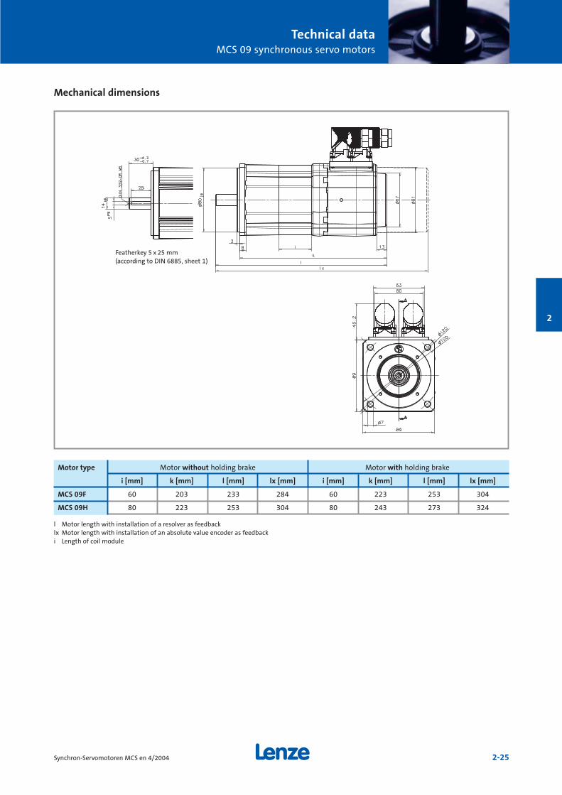
Mechanical dimensions
l Motor length with installation of a resolver as feedbacklx Motor length with installation of an absolute value encoder as feedbacki Length of coil module
Motor type Motor without holding brake Motor with holding brake
i [mm] k [mm] l [mm] lx [mm] i [mm] k [mm] l [mm] lx [mm]
MCS 09F 60 203 233 284 60 223 253 304
MCS 09H 80 223 253 304 80 243 273 324
Featherkey 5 x 25 mm(according to DIN 6885, sheet 1)
Technical dataMCS 09 synchronous servo motors
2-26 Synchron-Servomotoren MCS en 4/2004
2
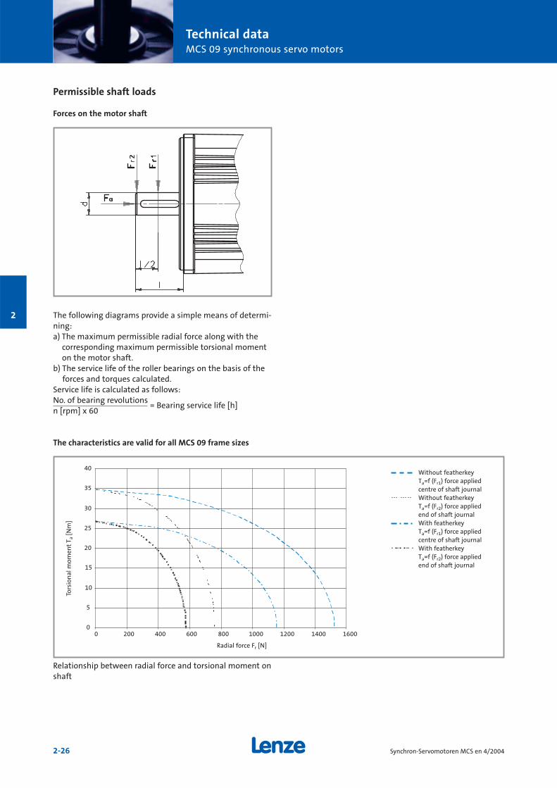
Permissible shaft loads
Forces on the motor shaft
The following diagrams provide a simple means of determi-ning: a) The maximum permissible radial force along with the
corresponding maximum permissible torsional momenton the motor shaft.
b) The service life of the roller bearings on the basis of theforces and torques calculated.
Service life is calculated as follows:No. of bearing revolutions
= Bearing service life [h]n [rpm] x 60
The characteristics are valid for all MCS 09 frame sizes
0
5
10
15
20
25
30
35
40
0 200 400 600 800 1000 1200 1400 1600
Relationship between radial force and torsional moment onshaft
Without featherkeyTa=f (Fr1) force appliedcentre of shaft journal Without featherkeyTa=f (Fr2) force appliedend of shaft journalWith featherkeyTa=f (Fr1) force appliedcentre of shaft journalWith featherkeyTa=f (Fr2) force appliedend of shaft journal
Radial force Fr [N]
Tors
ion
al m
omen
tT a
[Nm
]
Technical dataMCS 09 synchronous servo motors
2-27Synchron-Servomotoren MCS en 4/2004
2
0
200
400
600
800
1000
1200
-1000 -500 0 500 1000
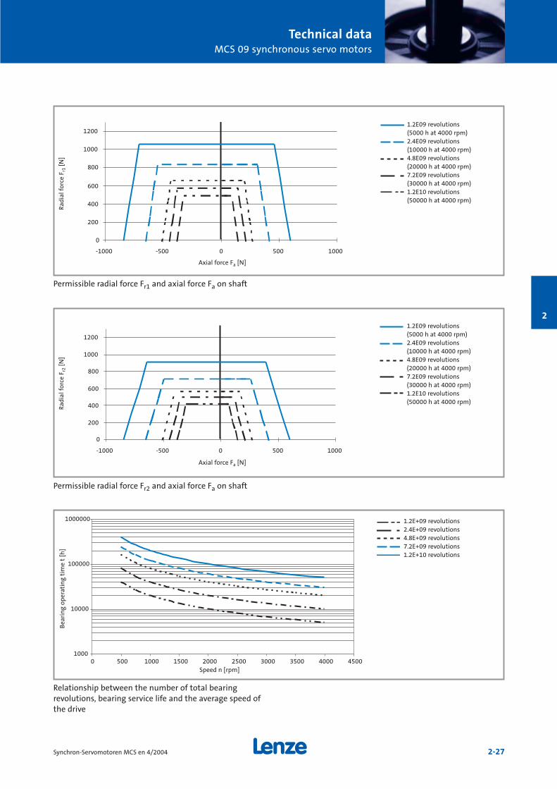
Permissible radial force Fr1 and axial force Fa on shaft
0
200
400
600
800
1000
1200
-1000 -500 0 500 1000
Permissible radial force Fr2 and axial force Fa on shaft
1000
10000
100000
1000000
0 500 1000 1500 2000 2500 3000 3500 4000 4500
Relationship between the number of total bearing revolutions, bearing service life and the average speed ofthe drive
1.2E09 revolutions(5000 h at 4000 rpm)2.4E09 revolutions(10000 h at 4000 rpm)4.8E09 revolutions(20000 h at 4000 rpm)7.2E09 revolutions(30000 h at 4000 rpm)1.2E10 revolutions(50000 h at 4000 rpm)
1.2E09 revolutions(5000 h at 4000 rpm)2.4E09 revolutions(10000 h at 4000 rpm)4.8E09 revolutions(20000 h at 4000 rpm)7.2E09 revolutions(30000 h at 4000 rpm)1.2E10 revolutions(50000 h at 4000 rpm)
1.2E+09 revolutions2.4E+09 revolutions4.8E+09 revolutions7.2E+09 revolutions1.2E+10 revolutions
Axial force Fa [N]
Rad
ial f
orce
Fr1
[N]
Axial force Fa [N]
Rad
ial f
orce
Fr2
[N]
Speed n [rpm]
Bea
rin
g op
erat
ing
tim
e t
[h]

2-28 Synchron-Servomotoren MCS en 4/2004
2
Technical dataMCS 12 synchronous servo motors
2-29Synchron-Servomotoren MCS en 4/2004
2
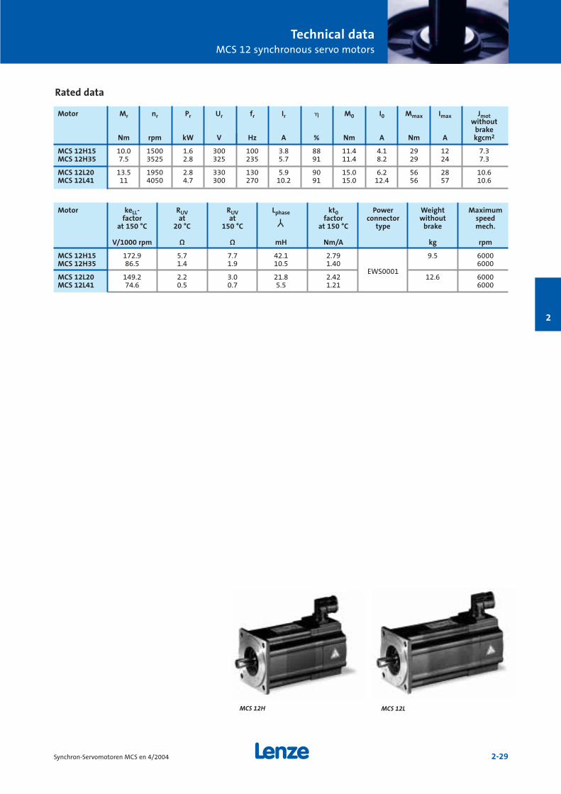
Rated data
Motor keLL- RUV RUV Lphase kt0 Power Weight Maximumfactor at at factor connector without speed
at 150 °C 20 °C 150 °C at 150 °C type brake mech.
V/1000 rpm Ω Ω mH Nm/A kg rpm
MCS 12H15 172.9 5.7 7.7 42.1 2.79 9.5 6000MCS 12H35 86.5 1.4 1.9 10.5 1.40 6000
MCS 12L20 149.2 2.2 3.0 21.8 2.42EWS0001
12.6 6000MCS 12L41 74.6 0.5 0.7 5.5 1.21 6000
Motor Mr nr Pr Ur fr Ir M0 I0 Mmax Imax Jmotwithout
brakeNm rpm kW V Hz A % Nm A Nm A kgcm2
MCS 12H15 10.0 1500 1.6 300 100 3.8 88 11.4 4.1 29 12 7.3MCS 12H35 7.5 3525 2.8 325 235 5.7 91 11.4 8.2 29 24 7.3
MCS 12L20 13.5 1950 2.8 330 130 5.9 90 15.0 6.2 56 28 10.6MCS 12L41 11 4050 4.7 300 270 10.2 91 15.0 12.4 56 57 10.6
MCS 12LMCS 12H

Technical dataMCS 12 synchronous servo motors
2-30 Synchron-Servomotoren MCS en 4/2004
2
Servo controller assignment
Assignment of ECS servo system – axis modules
Rated and maximum torques at a switching frequency of 4 kHz
Controller type ECSòA04 ECSòA08 ECSòA16 ECSòA32 ECSòA48 ECSòA64
Continuous current [A] 2 4 8 12.7 17 20
Maximum current 0 Hz 1) 2) [A] 2.3 4.6 9.1 18.1 27.2 36.3
Maximum current > 5 Hz 1) 2) [A] 4 8 16 32 48 64
Motor type
MCS 12H15 Mr 10.0 10.0
M0 11.2 11.4
Mmax n=0 11.9 22.6
Mmax 20.1 29.0
MCS 12H35 Mr 5.3 7.5 7.5
M0 5.6 11.2 11.4
Mmax n=0 6.0 11.8 22.5
Mmax 10.4 20.1 29.0
MCS 12L20 Mr 13.5 13.5
M0 15.0 15.0
Mmax n=0 21.4 39.4
Mmax 35.5 56.4
MCS 12L41 Mr 8.6 11.0 11.0 11.0
M0 9.7 15.0 15.0 15.0
Mmax n=0 10.8 21.3 30.8 39.5
Mmax 19.0 35.5 49.6 56.4
1) Caution: Limit Imax controller to Imax motor2) Caution: Max. heatsink temperature 9300 = 80 °C/ECS = 90 °C
and 400 V mains supply

Technical dataMCS 12 synchronous servo motors
2-31Synchron-Servomotoren MCS en 4/2004
2
Rated and maximum torques at a switching frequency of 8 kHz
Controller type ECSòA04 ECSòA08 ECSòA16 ECSòA32 ECSòA48 ECSòA64
Continuous current [A] 1.4 2.7 5.3 8.5 11.3 13.3
Maximum current 0 Hz 1) 2) 3) [A] 1.5 3 6 12.1 18.1 24.2
Maximum current > 5 Hz 1) 2) 3) [A] 2.7 5.3 10.7 21.3 32 42.7
Motor type
MCS 12H15 Mr 7.1 10.0
M0 7.5 11.4
Mmax n=0 7.8 15.4
Mmax 13.7 26.2
MCS 12H35 Mr 7.0 7.5 7.5
M0 7.4 11.4 11.4
Mmax n=0 7.8 15.5 22.5
Mmax 13.8 26.1 29.0
MCS 12L20 Mr 12.1 13.5 13.5
M0 12.8 15.0 15.0
Mmax n=0 14.3 27.7 39.4
Mmax 24.8 45.1 56.4
MCS 12L41 Mr 9.2 11.0 11.0
M0 10.3 13.7 15.0
Mmax n=0 14.4 21.3 27.7
Mmax 24.7 35.5 45.2
1) Caution: Limit Imax controller to Imax motor2) Caution: Max. heatsink temperature 9300 = 80 °C/ECS = 90 °C
and 400 V mains supply3) Caution: On the ECS automatic switching to 4 kHz not taken into account;
when using automatic switching to 4 kHz, the maximum torques at 4 kHzapply
Assignment of ECS servo system – axis modules
Technical dataMCS 12 synchronous servo motors
2-32 Synchron-Servomotoren MCS en 4/2004
2
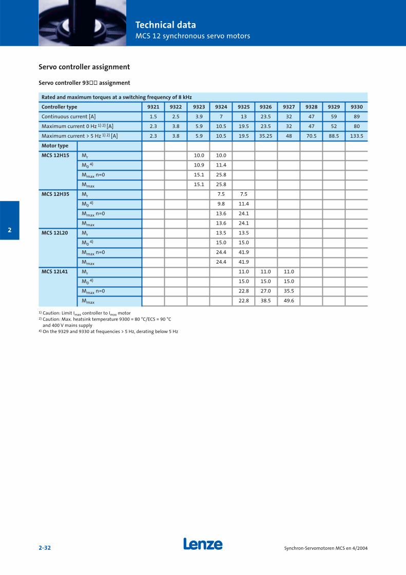
Rated and maximum torques at a switching frequency of 8 kHz
Controller type 9321 9322 9323 9324 9325 9326 9327 9328 9329 9330
Continuous current [A] 1.5 2.5 3.9 7 13 23.5 32 47 59 89
Maximum current 0 Hz 1) 2) [A] 2.3 3.8 5.9 10.5 19.5 23.5 32 47 52 80
Maximum current > 5 Hz 1) 2) [A] 2.3 3.8 5.9 10.5 19.5 35.25 48 70.5 88.5 133.5
Motor type
MCS 12H15 Mr 10.0 10.0
M04) 10.9 11.4
Mmax n=0 15.1 25.8
Mmax 15.1 25.8
MCS 12H35 Mr 7.5 7.5
M04) 9.8 11.4
Mmax n=0 13.6 24.1
Mmax 13.6 24.1
MCS 12L20 Mr 13.5 13.5
M04) 15.0 15.0
Mmax n=0 24.4 41.9
Mmax 24.4 41.9
MCS 12L41 Mr 11.0 11.0 11.0
M04) 15.0 15.0 15.0
Mmax n=0 22.8 27.0 35.5
Mmax 22.8 38.5 49.6
1) Caution: Limit Imax controller to Imax motor2) Caution: Max. heatsink temperature 9300 = 80 °C/ECS = 90 °C
and 400 V mains supply4) On the 9329 and 9330 at frequencies > 5 Hz, derating below 5 Hz
Servo controller assignment
Servo controller 93òò assignment
Technical dataMCS 12 synchronous servo motors
2-33Synchron-Servomotoren MCS en 4/2004
2
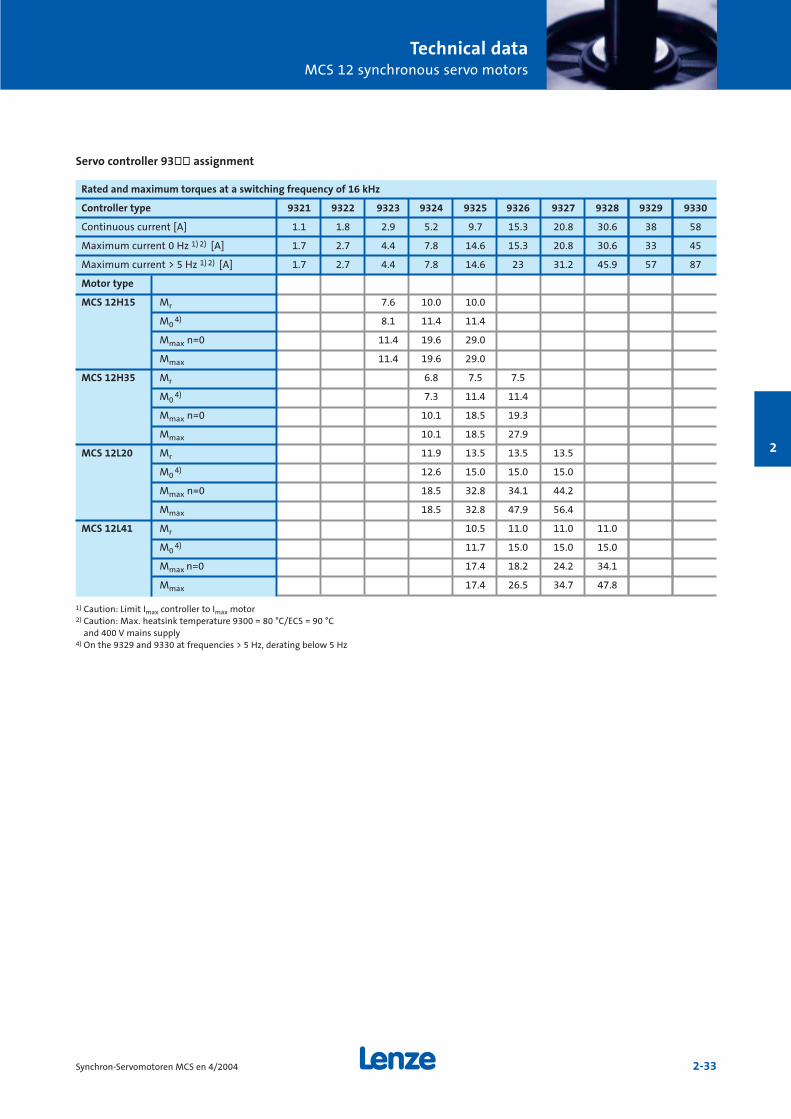
Rated and maximum torques at a switching frequency of 16 kHz
Controller type 9321 9322 9323 9324 9325 9326 9327 9328 9329 9330
Continuous current [A] 1.1 1.8 2.9 5.2 9.7 15.3 20.8 30.6 38 58
Maximum current 0 Hz 1) 2) [A] 1.7 2.7 4.4 7.8 14.6 15.3 20.8 30.6 33 45
Maximum current > 5 Hz 1) 2) [A] 1.7 2.7 4.4 7.8 14.6 23 31.2 45.9 57 87
Motor type
MCS 12H15 Mr 7.6 10.0 10.0
M04) 8.1 11.4 11.4
Mmax n=0 11.4 19.6 29.0
Mmax 11.4 19.6 29.0
MCS 12H35 Mr 6.8 7.5 7.5
M04) 7.3 11.4 11.4
Mmax n=0 10.1 18.5 19.3
Mmax 10.1 18.5 27.9
MCS 12L20 Mr 11.9 13.5 13.5 13.5
M04) 12.6 15.0 15.0 15.0
Mmax n=0 18.5 32.8 34.1 44.2
Mmax 18.5 32.8 47.9 56.4
MCS 12L41 Mr 10.5 11.0 11.0 11.0
M04) 11.7 15.0 15.0 15.0
Mmax n=0 17.4 18.2 24.2 34.1
Mmax 17.4 26.5 34.7 47.8
1) Caution: Limit Imax controller to Imax motor2) Caution: Max. heatsink temperature 9300 = 80 °C/ECS = 90 °C
and 400 V mains supply4) On the 9329 and 9330 at frequencies > 5 Hz, derating below 5 Hz
Servo controller 93òò assignment
Technical dataMCS 12 synchronous servo motors
2-34 Synchron-Servomotoren MCS en 4/2004
2
Torque characteristics
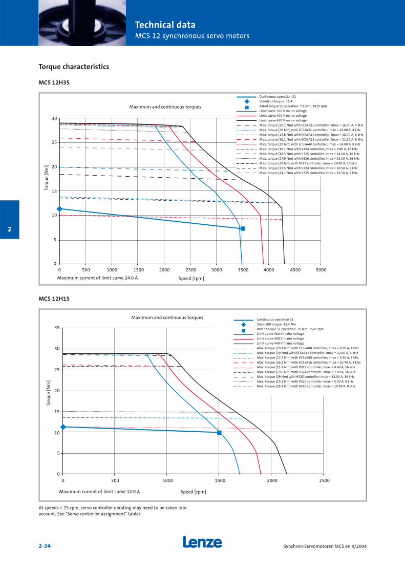
MCS 12H35
MCS 12H15
0
5
10
15
20
25
30
0 500 1000 1500 2000 2500 3000 3500 4000 4500 5000
0
5
10
15
20
25
30
35
0 500 1000 1500 2000 2500
Continuous operation S1
Standstill torque: 11.4
Rated torque S1 operation: 7.5 Nm; 3525 rpm
Limit curve 360 V mains voltage
Limit curve 400 V mains voltage
Limit curve 440 V mains voltage
Max. torque (20.1 Nm) with ECSxA16 controller; Imax = 16.00 A, 4 kHz
Max. torque (29 Nm) with ECSxA32 controller; Imax = 24.00 A, 4 kHz
Max. torque (13.8 Nm) with ECSxA16 controller; Imax = 10.70 A, 8 kHz
Max. torque (26.1 Nm) with ECSxA32 controller; Imax = 21.30 A, 8 kHz
Max. torque (29 Nm) with ECSxA48 controller; Imax = 24.00 A, 8 kHz
Max. torque (10.1 Nm) with 9324 controller; Imax = 7.80 A, 16 kHz
Max. torque (18.5 Nm) with 9325 controller; Imax = 14.60 A, 16 kHz
Max. torque (27.9 Nm) with 9326 controller; Imax = 23.00 A, 16 kHz
Max. torque (29 Nm) with 9327 controller; Imax = 24.00 A, 16 kHz
Max. torque (13.5 Nm) with 9324 controller; Imax = 10.50 A, 8 kHz
Max. torque (24.1 Nm) with 9325 controller; Imax = 19.50 A, 8 kHz
Maximum and continuous torques
Torq
ue
[Nm
]
Speed [rpm]Maximum current of limit curve 24.0 A
Continuous operation S1
Standstill torque: 11.4 Nm
Rated torque S1 operation: 10 Nm; 1500 rpm
Limit curve 360 V mains voltage
Limit curve 400 V mains voltage
Limit curve 440 V mains voltage
Max. torque (20.1 Nm) with ECSxA08 controller; Imax = 8.00 A, 4 kHz
Max. torque (29 Nm) with ECSxA16 controller; Imax = 12.00 A, 4 kHz
Max. torque (13.7 Nm) with ECSxA08 controller; Imax = 5.30 A, 8 kHz
Max. torque (26.2 Nm) with ECSxA16 controller; Imax = 10.70 A, 8 kHz
Max. torque (11.4 Nm) with 9323 controller; Imax = 4.40 A, 16 kHz
Max. torque (19.6 Nm) with 9324 controller; Imax = 7.80 A, 16 kHz
Max. torque (29 Nm) with 9325 controller; Imax = 12.00 A, 16 kHz
Max. torque (15.1 Nm) with 9323 controller; Imax = 5.90 A, 8 kHz
Max. torque (25.8 Nm) with 9324 controller; Imax = 10.50 A, 8 kHz
Maximum and continuous torques
Torq
ue
[Nm
]
Speed [rpm]Maximum current of limit curve 12.0 A
At speeds < 75 rpm, servo controller derating may need to be taken intoaccount. See "Servo controller assignment" tables.
Technical dataMCS 12 synchronous servo motors
2-35Synchron-Servomotoren MCS en 4/2004
2
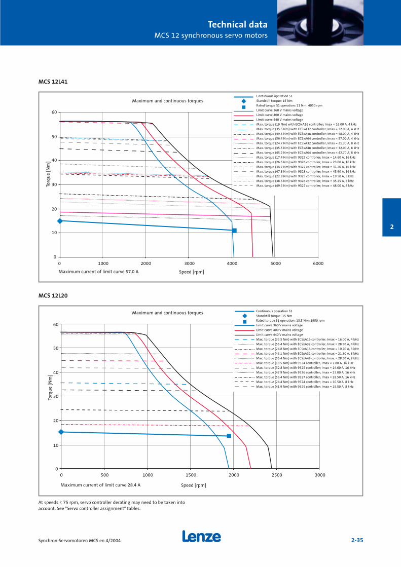
MCS 12L41
MCS 12L20
0
10
20
30
40
50
60
0 1000 2000 3000 4000 5000 6000
0
10
20
30
40
50
60
0 500 1000 1500 2000 2500 3000
Continuous operation S1
Standstill torque: 15 Nm
Rated torque S1 operation: 11 Nm; 4050 rpm
Limit curve 360 V mains voltage
Limit curve 400 V mains voltage
Limit curve 440 V mains voltage
Max. torque (19 Nm) with ECSxA16 controller; Imax = 16.00 A, 4 kHz
Max. torque (35.5 Nm) with ECSxA32 controller; Imax = 32.00 A, 4 kHz
Max. torque (49.5 Nm) with ECSxA48 controller; Imax = 48.00 A, 4 kHz
Max. torque (56.4 Nm) with ECSxA64 controller; Imax = 57.00 A, 4 kHz
Max. torque (24.7 Nm) with ECSxA32 controller; Imax = 21.30 A, 8 kHz
Max. torque (35.5 Nm) with ECSxA48 controller; Imax = 32.00 A, 8 kHz
Max. torque (45.2 Nm) with ECSxA64 controller; Imax = 42.70 A, 8 kHz
Max. torque (17.4 Nm) with 9325 controller; Imax = 14.60 A, 16 kHz
Max. torque (26.5 Nm) with 9326 controller; Imax = 23.00 A, 16 kHz
Max. torque (34.7 Nm) with 9327 controller; Imax = 31.20 A, 16 kHz
Max. torque (47.8 Nm) with 9328 controller; Imax = 45.90 A, 16 kHz
Max. torque (22.8 Nm) with 9325 controller; Imax = 19.50 A, 8 kHz
Max. torque (38.5 Nm) with 9326 controller; Imax = 35.25 A, 8 kHz
Max. torque (49.5 Nm) with 9327 controller; Imax = 48.00 A, 8 kHz
Continuous operation S1
Standstill torque: 15 Nm
Rated torque S1 operation: 13.5 Nm; 1950 rpm
Limit curve 360 V mains voltage
Limit curve 400 V mains voltage
Limit curve 440 V mains voltage
Max. torque (35.5 Nm) with ECSxA16 controller; Imax = 16.00 A, 4 kHz
Max. torque (56.4 Nm) with ECSxA32 controller; Imax = 28.50 A, 4 kHz
Max. torque (24.8 Nm) with ECSxA16 controller; Imax = 10.70 A, 8 kHz
Max. torque (45.1 Nm) with ECSxA32 controller; Imax = 21.30 A, 8 kHz
Max. torque (56.4 Nm) with ECSxA48 controller; Imax = 28.50 A, 8 kHz
Max. torque (18.5 Nm) with 9324 controller; Imax = 7.80 A, 16 kHz
Max. torque (32.8 Nm) with 9325 controller; Imax = 14.60 A, 16 kHz
Max. torque (47.9 Nm) with 9326 controller; Imax = 23.00 A, 16 kHz
Max. torque (56.4 Nm) with 9327 controller; Imax = 28.50 A, 16 kHz
Max. torque (24.4 Nm) with 9324 controller; Imax = 10.50 A, 8 kHz
Max. torque (41.9 Nm) with 9325 controller; Imax = 19.50 A, 8 kHz
Torq
ue
[Nm
]
Speed [rpm]Maximum current of limit curve 57.0 A
Maximum and continuous torques
Torq
ue
[Nm
]
Speed [rpm]Maximum current of limit curve 28.4 A
At speeds < 75 rpm, servo controller derating may need to be taken intoaccount. See "Servo controller assignment" tables.
Maximum and continuous torques
Technical dataMCS 12 synchronous servo motors
2-36 Synchron-Servomotoren MCS en 4/2004
2
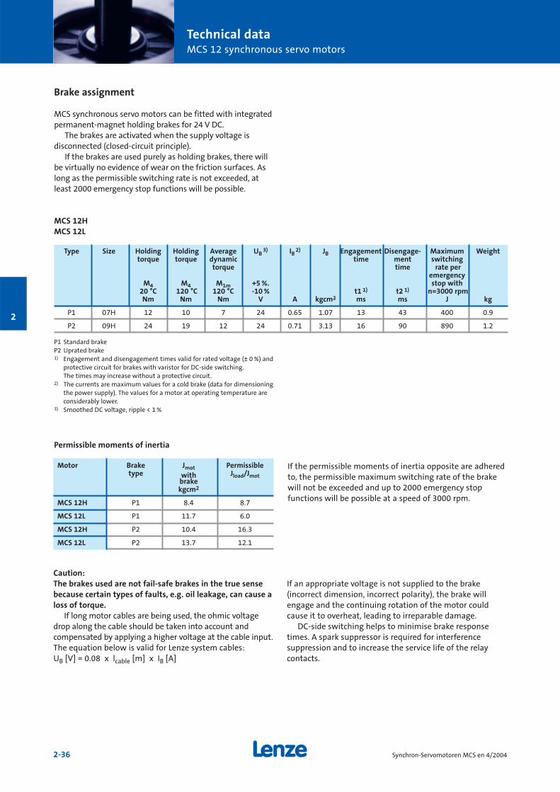
Brake assignment
MCS synchronous servo motors can be fitted with integratedpermanent-magnet holding brakes for 24 V DC.
The brakes are activated when the supply voltage is disconnected (closed-circuit principle).
If the brakes are used purely as holding brakes, there willbe virtually no evidence of wear on the friction surfaces. Aslong as the permissible switching rate is not exceeded, atleast 2000 emergency stop functions will be possible.
MCS 12HMCS 12L
P1 Standard brakeP2 Uprated brake1) Engagement and disengagement times valid for rated voltage (± 0 %) and
protective circuit for brakes with varistor for DC-side switching. The times may increase without a protective circuit.
2) The currents are maximum values for a cold brake (data for dimensioningthe power supply). The values for a motor at operating temperature areconsiderably lower.
3) Smoothed DC voltage, ripple < 1 %
If the permissible moments of inertia opposite are adheredto, the permissible maximum switching rate of the brakewill not be exceeded and up to 2000 emergency stop functions will be possible at a speed of 3000 rpm.
Motor Brake Jmot Permissibletype with Jload/Jmot
brakekgcm2
MCS 12H P1 8.4 8.7
MCS 12L P1 11.7 6.0
MCS 12H P2 10.4 16.3
MCS 12L P2 13.7 12.1
Permissible moments of inertia
Type Size Holding Holding Average UB3) IB
2) JB Engagement Disengage- Maximum Weighttorque torque dynamic time ment switching
torque time rate peremergency
M4 M4 M1m +5 %. stop with20 °C 120 °C 120 °C -10 % t1 1) t2 1) n=3000 rpmNm Nm Nm V A kgcm2 ms ms J kg
P1 07H 12 10 7 24 0.65 1.07 13 43 400 0.9
P2 09H 24 19 12 24 0.71 3.13 16 90 890 1.2
Caution:The brakes used are not fail-safe brakes in the true sensebecause certain types of faults, e.g. oil leakage, can cause aloss of torque.
If long motor cables are being used, the ohmic voltagedrop along the cable should be taken into account and compensated by applying a higher voltage at the cable input.The equation below is valid for Lenze system cables: UB [V] = 0.08 x lcable [m] x IB [A]
If an appropriate voltage is not supplied to the brake(incorrect dimension, incorrect polarity), the brake willengage and the continuing rotation of the motor couldcause it to overheat, leading to irreparable damage.
DC-side switching helps to minimise brake responsetimes. A spark suppressor is required for interference suppression and to increase the service life of the relaycontacts.
Technical dataMCS 12 synchronous servo motors
2-37Synchron-Servomotoren MCS en 4/2004
2
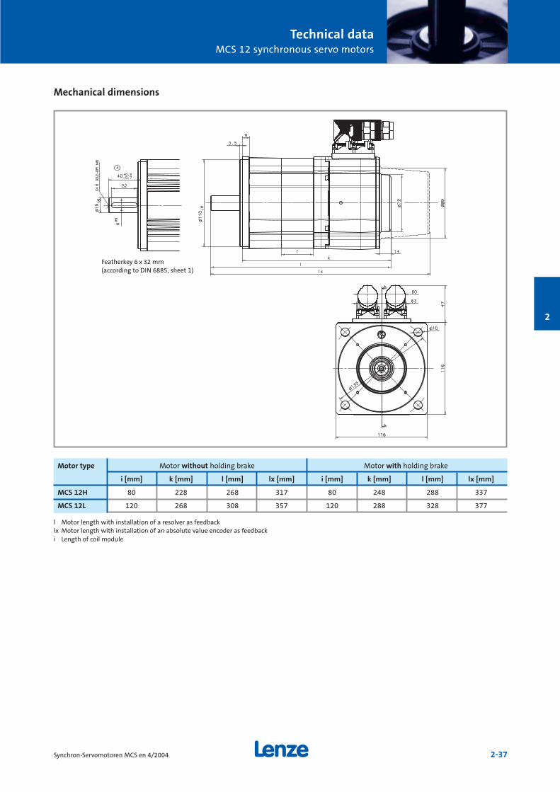
Mechanical dimensions
.
..
l Motor length with installation of a resolver as feedbacklx Motor length with installation of an absolute value encoder as feedbacki Length of coil module
Motor type Motor without holding brake Motor with holding brake
i [mm] k [mm] l [mm] lx [mm] i [mm] k [mm] l [mm] lx [mm]
MCS 12H 80 228 268 317 80 248 288 337
MCS 12L 120 268 308 357 120 288 328 377
Featherkey 6 x 32 mm(according to DIN 6885, sheet 1)

Technical dataMCS 12 synchronous servo motors
2-38 Synchron-Servomotoren MCS en 4/2004
2
Permissible shaft loads
Forces on the motor shaft
The following diagrams provide a simple means of determi-ning: a) The maximum permissible radial force along with the
corresponding maximum permissible torsional momenton the motor shaft.
b) The service life of the roller bearings on the basis of theforces and torques calculated.
Service life is calculated as follows:No. of bearing revolutions
= Bearing service life [h]n [rpm] x 60
The characteristics are valid for all MCS 12 frame sizes
0
10
20
30
40
50
60
70
80
90
0 500 1000 1500 2000 2500 3000
Relationship between radial force and torsional moment onshaft
Without featherkeyTa=f (Fr1) force appliedcentre of shaft journal Without featherkeyTa=f (Fr2) force appliedend of shaft journalWith featherkeyTa=f (Fr1) force appliedcentre of shaft journalWith featherkeyTa=f (Fr2) force appliedend of shaft journal
Radial force Fr [N]
Tors
ion
al m
omen
tT a
[Nm
]

Technical dataMCS 12 synchronous servo motors
2-39Synchron-Servomotoren MCS en 4/2004
2
0
200
400
600
800
1000
1200
1400
-1500 -1000 -500 0 500 1000
Permissible radial force Fr1 and axial force Fa on shaft
0100
300
500
700
900
1100
1300
1500
-1500 -1000 -500 0 500 1000
Permissible radial force Fr2 and axial force Fa on shaft
1000
10000
100000
1000000
0 500 1000 1500 2000 2500 3000 3500 4000 4500
Relationship between the number of total bearing revolutions, bearing service life and the average speed ofthe drive
1.2E09 revolutions(5000 h at 4000 rpm)2.4E09 revolutions(10000 h at 4000 rpm)4.8E09 revolutions(20000 h at 4000 rpm)7.2E09 revolutions(30000 h at 4000 rpm)1.2E10 revolutions(50000 h at 4000 rpm)
1.2E09 revolutions(5000 h at 4000 rpm)2.4E09 revolutions(10000 h at 4000 rpm)4.8E09 revolutions(20000 h at 4000 rpm)7.2E09 revolutions(30000 h at 4000 rpm)1.2E10 revolutions(50000 h at 4000 rpm)
1.2E+09 revolutions2.4E+09 revolutions4.8E+09 revolutions7.2E+09 revolutions1.2E+10 revolutions
Axial force Fa [N]
Rad
ial f
orce
Fr1
[N]
Axial force Fa [N]
Rad
ial f
orce
Fr2
[N]
Speed n [rpm]
Bea
rin
g op
erat
ing
tim
e t
[h]
Technical dataMCS 14 synchronous servo motors
2-40 Synchron-Servomotoren MCS en 4/2004
2
MCS 14D
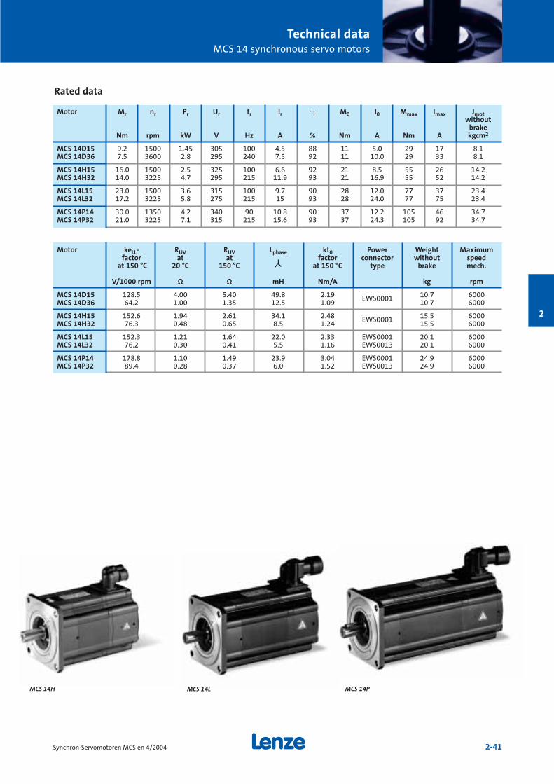
Technical dataMCS 14 synchronous servo motors
2-41Synchron-Servomotoren MCS en 4/2004
2
Rated data
Motor Mr nr Pr Ur fr Ir M0 I0 Mmax Imax Jmotwithout
brakeNm rpm kW V Hz A % Nm A Nm A kgcm2
MCS 14D15 9.2 1500 1.45 305 100 4.5 88 11 5.0 29 17 8.1MCS 14D36 7.5 3600 2.8 295 240 7.5 92 11 10.0 29 33 8.1
MCS 14H15 16.0 1500 2.5 325 100 6.6 92 21 8.5 55 26 14.2MCS 14H32 14.0 3225 4.7 295 215 11.9 93 21 16.9 55 52 14.2
MCS 14L15 23.0 1500 3.6 315 100 9.7 90 28 12.0 77 37 23.4MCS 14L32 17.2 3225 5.8 275 215 15 93 28 24.0 77 75 23.4
MCS 14P14 30.0 1350 4.2 340 90 10.8 90 37 12.2 105 46 34.7MCS 14P32 21.0 3225 7.1 315 215 15.6 93 37 24.3 105 92 34.7
Motor keLL- RUV RUV Lphase kt0 Power Weight Maximumfactor at at factor connector without speed
at 150 °C 20 °C 150 °C at 150 °C type brake mech.
V/1000 rpm Ω Ω mH Nm/A kg rpm
MCS 14D15 128.5 4.00 5.40 49.8 2.19 EWS0001 10.7 6000MCS 14D36 64.2 1.00 1.35 12.5 1.09 10.7 6000
MCS 14H15 152.6 1.94 2.61 34.1 2.48 EWS0001 15.5 6000MCS 14H32 76.3 0.48 0.65 8.5 1.24 15.5 6000
MCS 14L15 152.3 1.21 1.64 22.0 2.33 EWS0001 20.1 6000MCS 14L32 76.2 0.30 0.41 5.5 1.16 EWS0013 20.1 6000
MCS 14P14 178.8 1.10 1.49 23.9 3.04 EWS0001 24.9 6000MCS 14P32 89.4 0.28 0.37 6.0 1.52 EWS0013 24.9 6000
MCS 14LMCS 14H MCS 14P
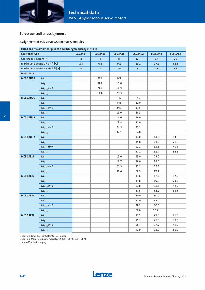
Technical dataMCS 14 synchronous servo motors
2-42 Synchron-Servomotoren MCS en 4/2004
2
Servo controller assignment
Assignment of ECS servo system – axis modules
Rated and maximum torques at a switching frequency of 4 kHz
Controller type ECSòA04 ECSòA08 ECSòA16 ECSòA32 ECSòA48 ECSòA64
Continuous current [A] 2 4 8 12.7 17 20
Maximum current 0 Hz 1) 2) [A] 2.3 4.6 9.1 18.1 27.2 36.3
Maximum current > 5 Hz 1) 2) [A] 4 8 16 32 48 64
Motor type
MCS 14D15 Mr 8.2 9.2
M0 8.8 11.0
Mmax n=0 9.6 17.9
Mmax 16.0 28.3
MCS 14D36 Mr 7.5 7.5
M0 8.8 11.0
Mmax n=0 9.5 17.8
Mmax 16.0 28.3
MCS 14H15 Mr 16.0 16.0
M0 19.8 21.0
Mmax n=0 22.3 41.2
Mmax 37.1 54.8
MCS 14H32 Mr 14.0 14.0 14.0
M0 15.8 21.0 21.0
Mmax n=0 22.2 32.1 41.3
Mmax 37.1 51.9 54.8
MCS 14L15 Mr 19.0 23.0 23.0
M0 18.7 28.0 28.0
Mmax n=0 21.9 42.1 59.9
Mmax 37.6 68.5 77.1
MCS 14L32 Mr 14.6 17.2 17.2
M0 14.8 19.8 23.3
Mmax n=0 21.8 32.4 42.2
Mmax 37.6 53.9 68.5
MCS 14P14 Mr 30.0 30.0
M0 37.0 37.0
Mmax n=0 49.1 70.0
Mmax 80.0 105.1
MCS 14P32 Mr 17.1 21.0 21.0
M0 19.3 25.9 30.5
Mmax n=0 25.4 37.9 49.3
Mmax 43.9 63.0 80.0
1) Caution: Limit Imax controller to Imax motor2) Caution: Max. heatsink temperature 9300 = 80 °C/ECS = 90 °C
and 400 V mains supply
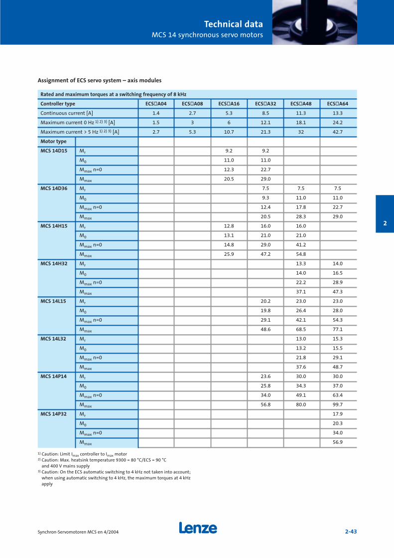
Technical dataMCS 14 synchronous servo motors
2-43Synchron-Servomotoren MCS en 4/2004
2
Rated and maximum torques at a switching frequency of 8 kHz
Controller type ECSòA04 ECSòA08 ECSòA16 ECSòA32 ECSòA48 ECSòA64
Continuous current [A] 1.4 2.7 5.3 8.5 11.3 13.3
Maximum current 0 Hz 1) 2) 3) [A] 1.5 3 6 12.1 18.1 24.2
Maximum current > 5 Hz 1) 2) 3) [A] 2.7 5.3 10.7 21.3 32 42.7
Motor type
MCS 14D15 Mr 9.2 9.2
M0 11.0 11.0
Mmax n=0 12.3 22.7
Mmax 20.5 29.0
MCS 14D36 Mr 7.5 7.5 7.5
M0 9.3 11.0 11.0
Mmax n=0 12.4 17.8 22.7
Mmax 20.5 28.3 29.0
MCS 14H15 Mr 12.8 16.0 16.0
M0 13.1 21.0 21.0
Mmax n=0 14.8 29.0 41.2
Mmax 25.9 47.2 54.8
MCS 14H32 Mr 13.3 14.0
M0 14.0 16.5
Mmax n=0 22.2 28.9
Mmax 37.1 47.3
MCS 14L15 Mr 20.2 23.0 23.0
M0 19.8 26.4 28.0
Mmax n=0 29.1 42.1 54.3
Mmax 48.6 68.5 77.1
MCS 14L32 Mr 13.0 15.3
M0 13.2 15.5
Mmax n=0 21.8 29.1
Mmax 37.6 48.7
MCS 14P14 Mr 23.6 30.0 30.0
M0 25.8 34.3 37.0
Mmax n=0 34.0 49.1 63.4
Mmax 56.8 80.0 99.7
MCS 14P32 Mr 17.9
M0 20.3
Mmax n=0 34.0
Mmax 56.9
1) Caution: Limit Imax controller to Imax motor2) Caution: Max. heatsink temperature 9300 = 80 °C/ECS = 90 °C
and 400 V mains supply3) Caution: On the ECS automatic switching to 4 kHz not taken into account;
when using automatic switching to 4 kHz, the maximum torques at 4 kHzapply
Assignment of ECS servo system – axis modules
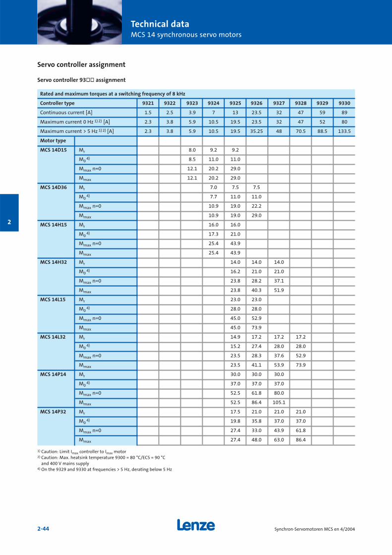
Technical dataMCS 14 synchronous servo motors
2-44 Synchron-Servomotoren MCS en 4/2004
2
Rated and maximum torques at a switching frequency of 8 kHz
Controller type 9321 9322 9323 9324 9325 9326 9327 9328 9329 9330
Continuous current [A] 1.5 2.5 3.9 7 13 23.5 32 47 59 89
Maximum current 0 Hz 1) 2) [A] 2.3 3.8 5.9 10.5 19.5 23.5 32 47 52 80
Maximum current > 5 Hz 1) 2) [A] 2.3 3.8 5.9 10.5 19.5 35.25 48 70.5 88.5 133.5
Motor type
MCS 14D15 Mr 8.0 9.2 9.2
M04) 8.5 11.0 11.0
Mmax n=0 12.1 20.2 29.0
Mmax 12.1 20.2 29.0
MCS 14D36 Mr 7.0 7.5 7.5
M04) 7.7 11.0 11.0
Mmax n=0 10.9 19.0 22.2
Mmax 10.9 19.0 29.0
MCS 14H15 Mr 16.0 16.0
M04) 17.3 21.0
Mmax n=0 25.4 43.9
Mmax 25.4 43.9
MCS 14H32 Mr 14.0 14.0 14.0
M04) 16.2 21.0 21.0
Mmax n=0 23.8 28.2 37.1
Mmax 23.8 40.3 51.9
MCS 14L15 Mr 23.0 23.0
M04) 28.0 28.0
Mmax n=0 45.0 52.9
Mmax 45.0 73.9
MCS 14L32 Mr 14.9 17.2 17.2 17.2
M04) 15.2 27.4 28.0 28.0
Mmax n=0 23.5 28.3 37.6 52.9
Mmax 23.5 41.1 53.9 73.9
MCS 14P14 Mr 30.0 30.0 30.0
M04) 37.0 37.0 37.0
Mmax n=0 52.5 61.8 80.0
Mmax 52.5 86.4 105.1
MCS 14P32 Mr 17.5 21.0 21.0 21.0
M04) 19.8 35.8 37.0 37.0
Mmax n=0 27.4 33.0 43.9 61.8
Mmax 27.4 48.0 63.0 86.4
1) Caution: Limit Imax controller to Imax motor2) Caution: Max. heatsink temperature 9300 = 80 °C/ECS = 90 °C
and 400 V mains supply4) On the 9329 and 9330 at frequencies > 5 Hz, derating below 5 Hz
Servo controller assignment
Servo controller 93òò assignment
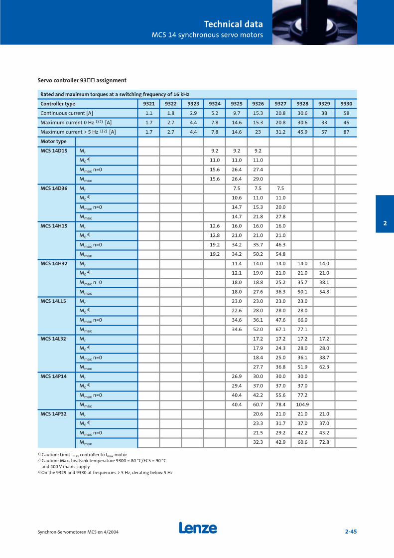
Technical dataMCS 14 synchronous servo motors
2-45Synchron-Servomotoren MCS en 4/2004
2
Rated and maximum torques at a switching frequency of 16 kHz
Controller type 9321 9322 9323 9324 9325 9326 9327 9328 9329 9330
Continuous current [A] 1.1 1.8 2.9 5.2 9.7 15.3 20.8 30.6 38 58
Maximum current 0 Hz 1) 2) [A] 1.7 2.7 4.4 7.8 14.6 15.3 20.8 30.6 33 45
Maximum current > 5 Hz 1) 2) [A] 1.7 2.7 4.4 7.8 14.6 23 31.2 45.9 57 87
Motor type
MCS 14D15 Mr 9.2 9.2 9.2
M04) 11.0 11.0 11.0
Mmax n=0 15.6 26.4 27.4
Mmax 15.6 26.4 29.0
MCS 14D36 Mr 7.5 7.5 7.5
M04) 10.6 11.0 11.0
Mmax n=0 14.7 15.3 20.0
Mmax 14.7 21.8 27.8
MCS 14H15 Mr 12.6 16.0 16.0 16.0
M04) 12.8 21.0 21.0 21.0
Mmax n=0 19.2 34.2 35.7 46.3
Mmax 19.2 34.2 50.2 54.8
MCS 14H32 Mr 11.4 14.0 14.0 14.0 14.0
M04) 12.1 19.0 21.0 21.0 21.0
Mmax n=0 18.0 18.8 25.2 35.7 38.1
Mmax 18.0 27.6 36.3 50.1 54.8
MCS 14L15 Mr 23.0 23.0 23.0 23.0
M04) 22.6 28.0 28.0 28.0
Mmax n=0 34.6 36.1 47.6 66.0
Mmax 34.6 52.0 67.1 77.1
MCS 14L32 Mr 17.2 17.2 17.2 17.2
M04) 17.9 24.3 28.0 28.0
Mmax n=0 18.4 25.0 36.1 38.7
Mmax 27.7 36.8 51.9 62.3
MCS 14P14 Mr 26.9 30.0 30.0 30.0
M04) 29.4 37.0 37.0 37.0
Mmax n=0 40.4 42.2 55.6 77.2
Mmax 40.4 60.7 78.4 104.9
MCS 14P32 Mr 20.6 21.0 21.0 21.0
M04) 23.3 31.7 37.0 37.0
Mmax n=0 21.5 29.2 42.2 45.2
Mmax 32.3 42.9 60.6 72.8
1) Caution: Limit Imax controller to Imax motor2) Caution: Max. heatsink temperature 9300 = 80 °C/ECS = 90 °C
and 400 V mains supply4) On the 9329 and 9330 at frequencies > 5 Hz, derating below 5 Hz
Servo controller 93òò assignment
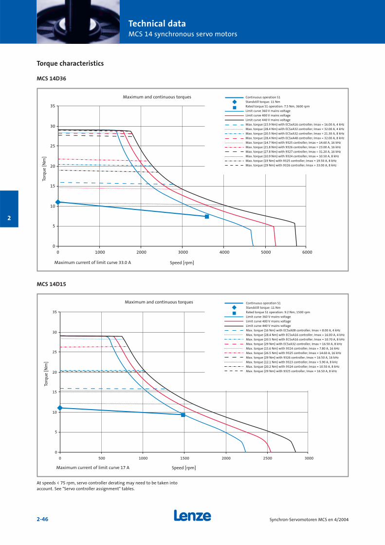
Technical dataMCS 14 synchronous servo motors
2-46 Synchron-Servomotoren MCS en 4/2004
2
Torque characteristics
MCS 14D36
MCS 14D15
0
5
10
15
20
25
30
35
0 1000 2000 3000 4000 5000 6000
0
5
10
15
20
25
30
35
0 500 1000 1500 2000 2500 3000
Continuous operation S1
Standstill torque: 11 Nm
Rated torque S1 operation: 7.5 Nm; 3600 rpm
Limit curve 360 V mains voltage
Limit curve 400 V mains voltage
Limit curve 440 V mains voltage
Max. torque (15.9 Nm) with ECSxA16 controller; Imax = 16.00 A, 4 kHz
Max. torque (28.4 Nm) with ECSxA32 controller; Imax = 32.00 A, 4 kHz
Max. torque (20.5 Nm) with ECSxA32 controller; Imax = 21.30 A, 8 kHz
Max. torque (28.4 Nm) with ECSxA48 controller; Imax = 32.00 A, 8 kHz
Max. torque (14.7 Nm) with 9325 controller; Imax = 14.60 A, 16 kHz
Max. torque (21.8 Nm) with 9326 controller; Imax = 23.00 A, 16 kHz
Max. torque (27.8 Nm) with 9327 controller; Imax = 31.20 A, 16 kHz
Max. torque (10.9 Nm) with 9324 controller; Imax = 10.50 A, 8 kHz
Max. torque (19 Nm) with 9325 controller; Imax = 19.50 A, 8 kHz
Max. torque (29 Nm) with 9326 controller; Imax = 33.00 A, 8 kHz
Maximum and continuous torques
Torq
ue
[Nm
]
Speed [rpm]Maximum current of limit curve 33.0 A
Continuous operation S1
Standstill torque: 11 Nm
Rated torque S1 operation: 9.2 Nm; 1500 rpm
Limit curve 360 V mains voltage
Limit curve 400 V mains voltage
Limit curve 440 V mains voltage
Max. torque (16 Nm) with ECSxA08 controller; Imax = 8.00 A, 4 kHz
Max. torque (28.4 Nm) with ECSxA16 controller; Imax = 16.00 A, 4 kHz
Max. torque (20.5 Nm) with ECSxA16 controller; Imax = 10.70 A, 8 kHz
Max. torque (29 Nm) with ECSxA32 controller; Imax = 16.50 A, 8 kHz
Max. torque (15.6 Nm) with 9324 controller; Imax = 7.80 A, 16 kHz
Max. torque (26.5 Nm) with 9325 controller; Imax = 14.60 A, 16 kHz
Max. torque (29 Nm) with 9326 controller; Imax = 16.50 A, 16 kHz
Max. torque (12.1 Nm) with 9323 controller; Imax = 5.90 A, 8 kHz
Max. torque (20.2 Nm) with 9324 controller; Imax = 10.50 A, 8 kHz
Max. torque (29 Nm) with 9325 controller; Imax = 16.50 A, 8 kHz
Maximum and continuous torques
Torq
ue
[Nm
]
Speed [rpm]Maximum current of limit curve 17 A
At speeds < 75 rpm, servo controller derating may need to be taken intoaccount. See "Servo controller assignment" tables.
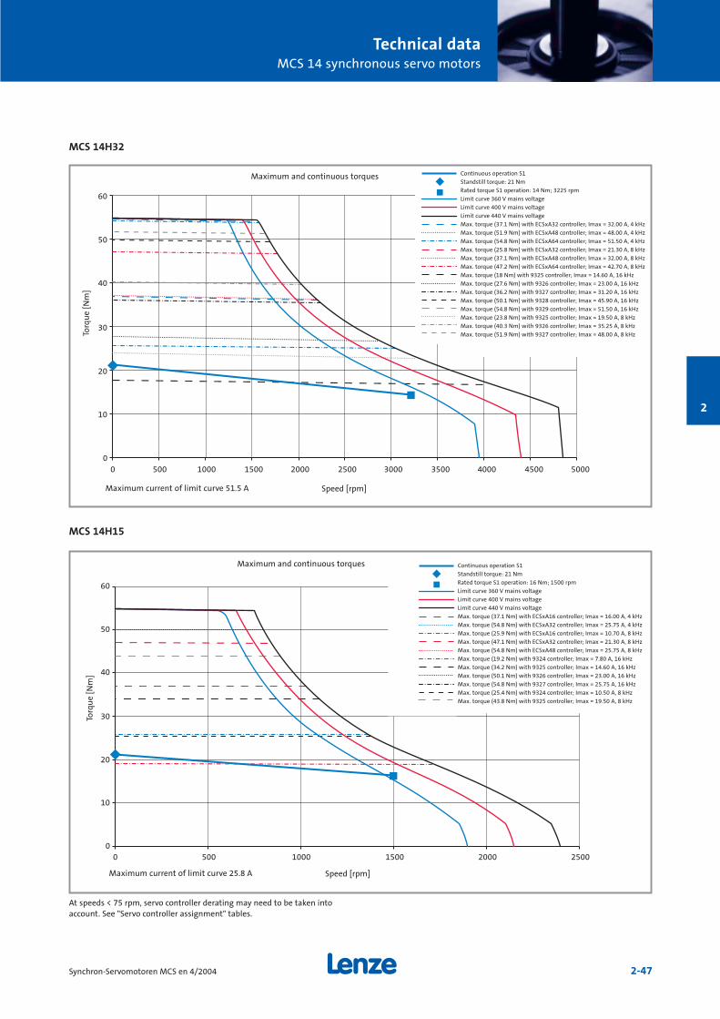
Technical dataMCS 14 synchronous servo motors
2-47Synchron-Servomotoren MCS en 4/2004
2
MCS 14H32
MCS 14H15
0
10
20
30
40
50
60
0 500 1000 1500 2000 2500 3000 3500 4000 4500 5000
0
10
20
30
40
50
60
0 500 1000 1500 2000 2500
Continuous operation S1
Standstill torque: 21 Nm
Rated torque S1 operation: 14 Nm; 3225 rpm
Limit curve 360 V mains voltage
Limit curve 400 V mains voltage
Limit curve 440 V mains voltage
Max. torque (37.1 Nm) with ECSxA32 controller; Imax = 32.00 A, 4 kHz
Max. torque (51.9 Nm) with ECSxA48 controller; Imax = 48.00 A, 4 kHz
Max. torque (54.8 Nm) with ECSxA64 controller; Imax = 51.50 A, 4 kHz
Max. torque (25.8 Nm) with ECSxA32 controller; Imax = 21.30 A, 8 kHz
Max. torque (37.1 Nm) with ECSxA48 controller; Imax = 32.00 A, 8 kHz
Max. torque (47.2 Nm) with ECSxA64 controller; Imax = 42.70 A, 8 kHz
Max. torque (18 Nm) with 9325 controller; Imax = 14.60 A, 16 kHz
Max. torque (27.6 Nm) with 9326 controller; Imax = 23.00 A, 16 kHz
Max. torque (36.2 Nm) with 9327 controller; Imax = 31.20 A, 16 kHz
Max. torque (50.1 Nm) with 9328 controller; Imax = 45.90 A, 16 kHz
Max. torque (54.8 Nm) with 9329 controller; Imax = 51.50 A, 16 kHz
Max. torque (23.8 Nm) with 9325 controller; Imax = 19.50 A, 8 kHz
Max. torque (40.3 Nm) with 9326 controller; Imax = 35.25 A, 8 kHz
Max. torque (51.9 Nm) with 9327 controller; Imax = 48.00 A, 8 kHz
Continuous operation S1
Standstill torque: 21 Nm
Rated torque S1 operation: 16 Nm; 1500 rpm
Limit curve 360 V mains voltage
Limit curve 400 V mains voltage
Limit curve 440 V mains voltage
Max. torque (37.1 Nm) with ECSxA16 controller; Imax = 16.00 A, 4 kHz
Max. torque (54.8 Nm) with ECSxA32 controller; Imax = 25.75 A, 4 kHz
Max. torque (25.9 Nm) with ECSxA16 controller; Imax = 10.70 A, 8 kHz
Max. torque (47.1 Nm) with ECSxA32 controller; Imax = 21.30 A, 8 kHz
Max. torque (54.8 Nm) with ECSxA48 controller; Imax = 25.75 A, 8 kHz
Max. torque (19.2 Nm) with 9324 controller; Imax = 7.80 A, 16 kHz
Max. torque (34.2 Nm) with 9325 controller; Imax = 14.60 A, 16 kHz
Max. torque (50.1 Nm) with 9326 controller; Imax = 23.00 A, 16 kHz
Max. torque (54.8 Nm) with 9327 controller; Imax = 25.75 A, 16 kHz
Max. torque (25.4 Nm) with 9324 controller; Imax = 10.50 A, 8 kHz
Max. torque (43.8 Nm) with 9325 controller; Imax = 19.50 A, 8 kHz
Torq
ue
[Nm
]
Speed [rpm]Maximum current of limit curve 51.5 A
Maximum and continuous torques
Torq
ue
[Nm
]
Speed [rpm]Maximum current of limit curve 25.8 A
Maximum and continuous torques
At speeds < 75 rpm, servo controller derating may need to be taken intoaccount. See "Servo controller assignment" tables.
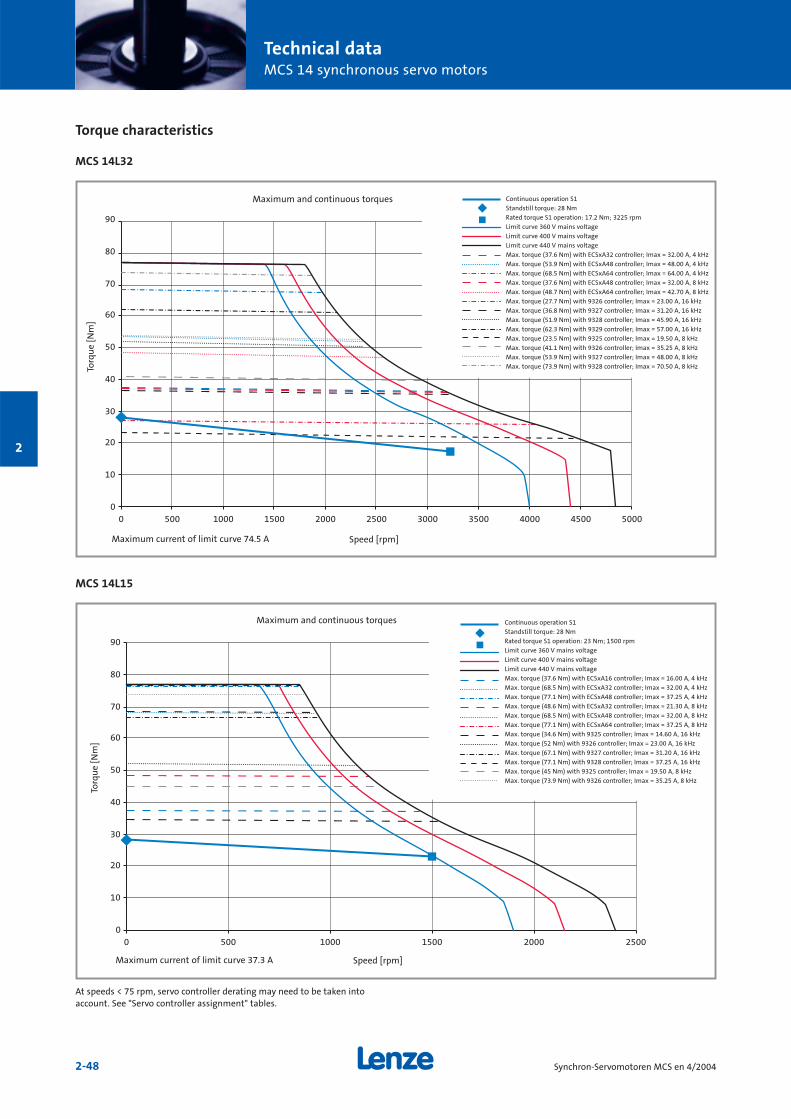
Technical dataMCS 14 synchronous servo motors
2-48 Synchron-Servomotoren MCS en 4/2004
2
Torque characteristics
MCS 14L32
MCS 14L15
0
10
20
30
40
50
60
70
80
90
0 500 1000 1500 2000 2500 3000 3500 4000 4500 5000
0
10
20
30
40
50
60
70
80
90
0 500 1000 1500 2000 2500
Continuous operation S1
Standstill torque: 28 Nm
Rated torque S1 operation: 17.2 Nm; 3225 rpm
Limit curve 360 V mains voltage
Limit curve 400 V mains voltage
Limit curve 440 V mains voltage
Max. torque (37.6 Nm) with ECSxA32 controller; Imax = 32.00 A, 4 kHz
Max. torque (53.9 Nm) with ECSxA48 controller; Imax = 48.00 A, 4 kHz
Max. torque (68.5 Nm) with ECSxA64 controller; Imax = 64.00 A, 4 kHz
Max. torque (37.6 Nm) with ECSxA48 controller; Imax = 32.00 A, 8 kHz
Max. torque (48.7 Nm) with ECSxA64 controller; Imax = 42.70 A, 8 kHz
Max. torque (27.7 Nm) with 9326 controller; Imax = 23.00 A, 16 kHz
Max. torque (36.8 Nm) with 9327 controller; Imax = 31.20 A, 16 kHz
Max. torque (51.9 Nm) with 9328 controller; Imax = 45.90 A, 16 kHz
Max. torque (62.3 Nm) with 9329 controller; Imax = 57.00 A, 16 kHz
Max. torque (23.5 Nm) with 9325 controller; Imax = 19.50 A, 8 kHz
Max. torque (41.1 Nm) with 9326 controller; Imax = 35.25 A, 8 kHz
Max. torque (53.9 Nm) with 9327 controller; Imax = 48.00 A, 8 kHz
Max. torque (73.9 Nm) with 9328 controller; Imax = 70.50 A, 8 kHz
Maximum and continuous torques
Torq
ue
[Nm
]
Speed [rpm]Maximum current of limit curve 74.5 A
Continuous operation S1
Standstill torque: 28 Nm
Rated torque S1 operation: 23 Nm; 1500 rpm
Limit curve 360 V mains voltage
Limit curve 400 V mains voltage
Limit curve 440 V mains voltage
Max. torque (37.6 Nm) with ECSxA16 controller; Imax = 16.00 A, 4 kHz
Max. torque (68.5 Nm) with ECSxA32 controller; Imax = 32.00 A, 4 kHz
Max. torque (77.1 Nm) with ECSxA48 controller; Imax = 37.25 A, 4 kHz
Max. torque (48.6 Nm) with ECSxA32 controller; Imax = 21.30 A, 8 kHz
Max. torque (68.5 Nm) with ECSxA48 controller; Imax = 32.00 A, 8 kHz
Max. torque (77.1 Nm) with ECSxA64 controller; Imax = 37.25 A, 8 kHz
Max. torque (34.6 Nm) with 9325 controller; Imax = 14.60 A, 16 kHz
Max. torque (52 Nm) with 9326 controller; Imax = 23.00 A, 16 kHz
Max. torque (67.1 Nm) with 9327 controller; Imax = 31.20 A, 16 kHz
Max. torque (77.1 Nm) with 9328 controller; Imax = 37.25 A, 16 kHz
Max. torque (45 Nm) with 9325 controller; Imax = 19.50 A, 8 kHz
Max. torque (73.9 Nm) with 9326 controller; Imax = 35.25 A, 8 kHz
Maximum and continuous torques
Torq
ue
[Nm
]
Speed [rpm]Maximum current of limit curve 37.3 A
At speeds < 75 rpm, servo controller derating may need to be taken intoaccount. See "Servo controller assignment" tables.
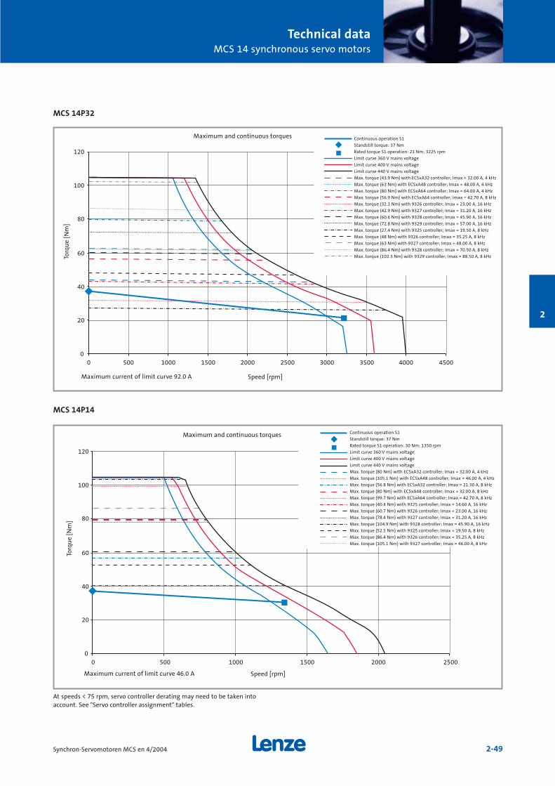
Technical dataMCS 14 synchronous servo motors
2-49Synchron-Servomotoren MCS en 4/2004
2
MCS 14P32
MCS 14P14
0
20
40
60
80
100
120
0 500 1000 1500 2000 2500 3000 3500 4000 4500
0
20
40
60
80
100
120
0 500 1000 1500 2000 2500
Continuous operation S1
Standstill torque: 37 Nm
Rated torque S1 operation: 21 Nm; 3225 rpm
Limit curve 360 V mains voltage
Limit curve 400 V mains voltage
Limit curve 440 V mains voltage
Max. torque (43.9 Nm) with ECSxA32 controller; Imax = 32.00 A, 4 kHz
Max. torque (63 Nm) with ECSxA48 controller; Imax = 48.00 A, 4 kHz
Max. torque (80 Nm) with ECSxA64 controller; Imax = 64.00 A, 4 kHz
Max. torque (56.9 Nm) with ECSxA64 controller; Imax = 42.70 A, 8 kHz
Max. torque (32.3 Nm) with 9326 controller; Imax = 23.00 A, 16 kHz
Max. torque (42.9 Nm) with 9327 controller; Imax = 31.20 A, 16 kHz
Max. torque (60.6 Nm) with 9328 controller; Imax = 45.90 A, 16 kHz
Max. torque (72.8 Nm) with 9329 controller; Imax = 57.00 A, 16 kHz
Max. torque (27.4 Nm) with 9325 controller; Imax = 19.50 A, 8 kHz
Max. torque (48 Nm) with 9326 controller; Imax = 35.25 A, 8 kHz
Max. torque (63 Nm) with 9327 controller; Imax = 48.00 A, 8 kHz
Max. torque (86.4 Nm) with 9328 controller; Imax = 70.50 A, 8 kHz
Max. torque (102.3 Nm) with 9329 controller; Imax = 88.50 A, 8 kHz
Continuous operation S1
Standstill torque: 37 Nm
Rated torque S1 operation: 30 Nm; 1350 rpm
Limit curve 360 V mains voltage
Limit curve 400 V mains voltage
Limit curve 440 V mains voltage
Max. torque (80 Nm) with ECSxA32 controller; Imax = 32.00 A, 4 kHz
Max. torque (105.1 Nm) with ECSxA48 controller; Imax = 46.00 A, 4 kHz
Max. torque (56.8 Nm) with ECSxA32 controller; Imax = 21.30 A, 8 kHz
Max. torque (80 Nm) with ECSxA48 controller; Imax = 32.00 A, 8 kHz
Max. torque (99.7 Nm) with ECSxA64 controller; Imax = 42.70 A, 8 kHz
Max. torque (40.4 Nm) with 9325 controller; Imax = 14.60 A, 16 kHz
Max. torque (60.7 Nm) with 9326 controller; Imax = 23.00 A, 16 kHz
Max. torque (78.4 Nm) with 9327 controller; Imax = 31.20 A, 16 kHz
Max. torque (104.9 Nm) with 9328 controller; Imax = 45.90 A, 16 kHz
Max. torque (52.5 Nm) with 9325 controller; Imax = 19.50 A, 8 kHz
Max. torque (86.4 Nm) with 9326 controller; Imax = 35.25 A, 8 kHz
Max. torque (105.1 Nm) with 9327 controller; Imax = 46.00 A, 8 kHz
Torq
ue
[Nm
]
Speed [rpm]Maximum current of limit curve 92.0 A
Maximum and continuous torques
Torq
ue
[Nm
]
Speed [rpm]Maximum current of limit curve 46.0 A
Maximum and continuous torques
At speeds < 75 rpm, servo controller derating may need to be taken intoaccount. See "Servo controller assignment" tables.
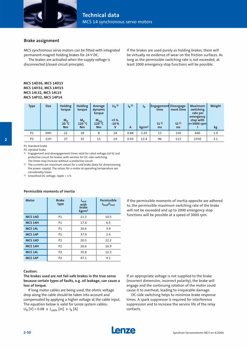
Technical dataMCS 14 synchronous servo motors
2-50 Synchron-Servomotoren MCS en 4/2004
2
Brake assignment
MCS synchronous servo motors can be fitted with integratedpermanent-magnet holding brakes for 24 V DC.
The brakes are activated when the supply voltage is disconnected (closed-circuit principle).
P1 Standard brakeP2 Uprated brake1) Engagement and disengagement times valid for rated voltage (±0 %) and
protective circuit for brakes with varistor for DC-side switching. The times may increase without a protective circuit.
2) The currents are maximum values for a cold brake (data for dimensioningthe power supply). The values for a motor at operating temperature areconsiderably lower.
3) Smoothed DC voltage, ripple < 1 %
If the permissible moments of inertia opposite are adheredto, the permissible maximum switching rate of the brakewill not be exceeded and up to 2000 emergency stop functions will be possible at a speed of 3000 rpm.
Motor Brake Jmot Permissibletype with Jload/Jmot
brakekgcm2
MCS 14D P1 11.3 10.5
MCS 14H P1 17.4 6.5
MCS 14L P1 26.6 3.9
MCS 14P P1 37.9 2.4
MCS 14D P2 20.5 22.2
MCS 14H P2 26.6 16.9
MCS 14L P2 35.8 12.3
MCS 14P P2 47.1 9.1
Permissible moments of inertia
Type Size Holding Holding Average UB3) IB
2) JB Engagement Disengage- Maximum Weighttorque torque dynamic time ment time switching
torque rate peremergency
M4 M4 M1m +5 %. stop with 20 °C 120 °C 120 °C -10 % t1 1) t2 1) n=3000 rpmNm Nm Nm V A kgcm2 ms ms J kg
P1 09H 22 18 8 24 0.88 3.20 15 150 640 1.9
P2 11H 37 32 15 24 0.93 12.4 96 113 2350 3.1
Caution:The brakes used are not fail-safe brakes in the true sensebecause certain types of faults, e.g. oil leakage, can cause aloss of torque.
If long motor cables are being used, the ohmic voltagedrop along the cable should be taken into account andcompensated by applying a higher voltage at the cable input.The equation below is valid for Lenze system cables: UB [V] = 0.08 x lcable [m] x IB [A]
If an appropriate voltage is not supplied to the brake (incorrect dimension, incorrect polarity), the brake willengage and the continuing rotation of the motor couldcause it to overheat, leading to irreparable damage.
DC-side switching helps to minimise brake responsetimes. A spark suppressor is required for interference suppression and to increase the service life of the relaycontacts.
MCS 14D36, MCS 14D15MCS 14H32, MCS 14H15MCS 14L32, MCS 14L15MCS 14P32, MCS 14P14
If the brakes are used purely as holding brakes, there willbe virtually no evidence of wear on the friction surfaces. Aslong as the permissible switching rate is not exceeded, atleast 2000 emergency stop functions will be possible.
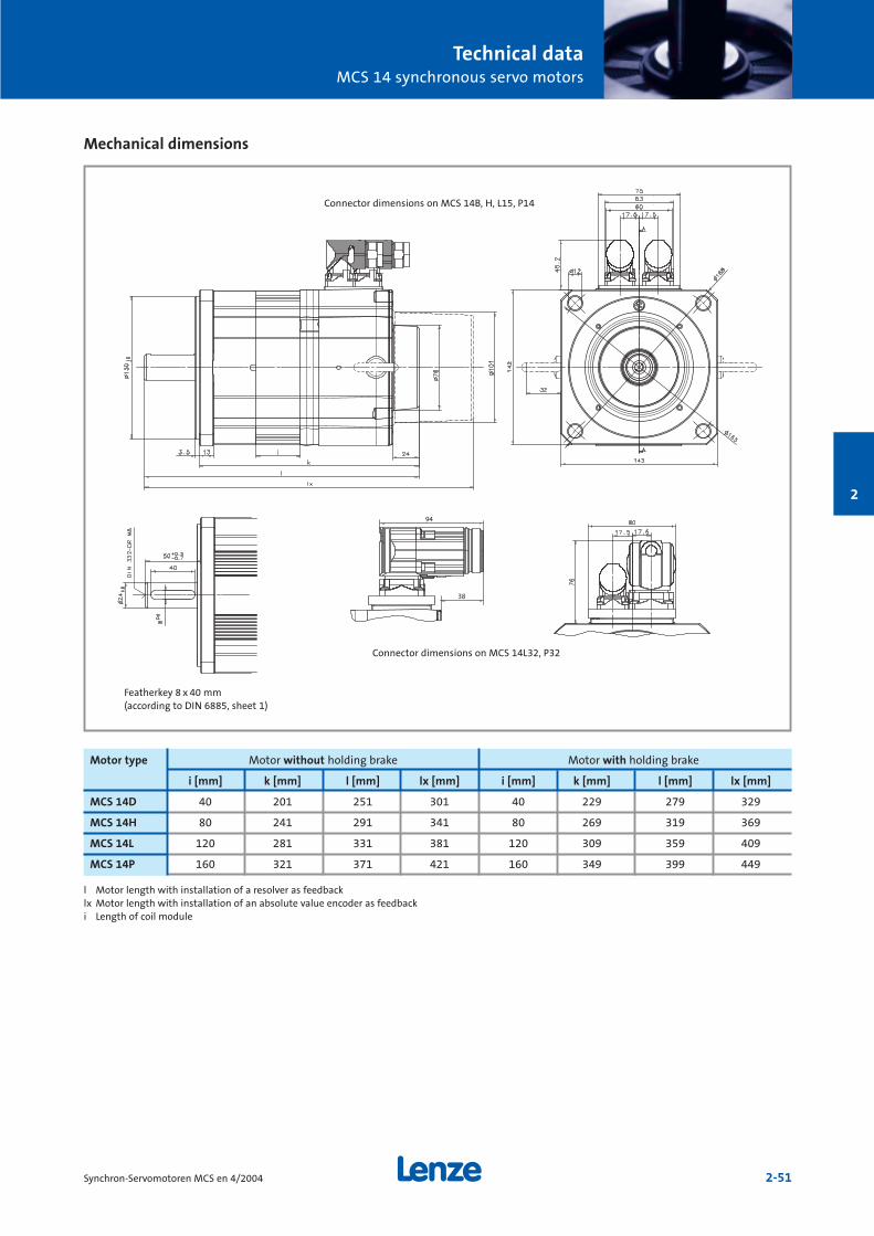
Technical dataMCS 14 synchronous servo motors
2-51Synchron-Servomotoren MCS en 4/2004
2
Mechanical dimensions
l Motor length with installation of a resolver as feedbacklx Motor length with installation of an absolute value encoder as feedbacki Length of coil module
Motor type Motor without holding brake Motor with holding brake
i [mm] k [mm] l [mm] lx [mm] i [mm] k [mm] l [mm] lx [mm]
MCS 14D 40 201 251 301 40 229 279 329
MCS 14H 80 241 291 341 80 269 319 369
MCS 14L 120 281 331 381 120 309 359 409
MCS 14P 160 321 371 421 160 349 399 449
Connector dimensions on MCS 14B, H, L15, P14
Connector dimensions on MCS 14L32, P32
Featherkey 8 x 40 mm(according to DIN 6885, sheet 1)

Technical dataMCS 14 synchronous servo motors
2-52 Synchron-Servomotoren MCS en 4/2004
2
Permissible shaft loads
Forces on the motor shaft
The following diagrams provide a simple means of determi-ning: a) The maximum permissible radial force along with the
corresponding maximum permissible torsional momenton the motor shaft.
b) The service life of the roller bearings on the basis of theforces and torques calculated.
Service life is calculated as follows:No. of bearing revolutions
= Bearing service life [h]n [rpm] x 60
The characteristics are valid for all MCS 14 frame sizes
0
20
40
60
80
100
120
140
160
0 500 1000 1500 2000 2500 3000 3500 4000
Relationship between radial force and torsional moment onshaft
Without featherkeyTa=f (Fr1) force appliedcentre of shaft journalWithout featherkeyTa=f (Fr2) force appliedend of shaft journalWith featherkeyTa=f (Fr1) force appliedcentre of shaft journalWith featherkeyTa=f (Fr2) force appliedend of shaft journal
Radial force Fr [N]
Tors
ion
al m
omen
tT a
[Nm
]
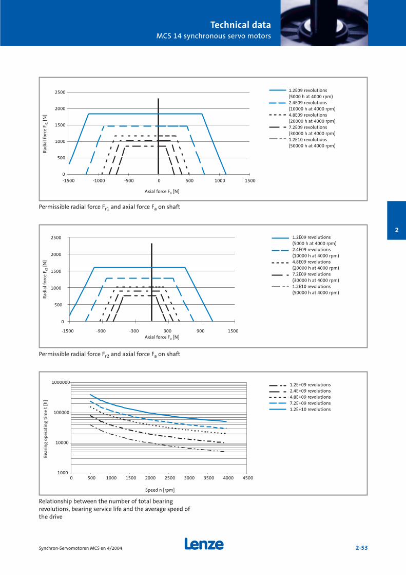
Technical dataMCS 14 synchronous servo motors
2-53Synchron-Servomotoren MCS en 4/2004
2
0
500
1000
1500
2000
2500
-1500 -1000 -500 0 500 1000 1500
Permissible radial force Fr1 and axial force Fa on shaft
0
500
1000
1500
2000
2500
-1500 -900 -300 300 900 1500
Permissible radial force Fr2 and axial force Fa on shaft
1000
10000
100000
1000000
0 500 1000 1500 2000 2500 3000 3500 4000 4500
Relationship between the number of total bearing revolutions, bearing service life and the average speed ofthe drive
1.2E09 revolutions(5000 h at 4000 rpm)2.4E09 revolutions(10000 h at 4000 rpm)4.8E09 revolutions(20000 h at 4000 rpm)7.2E09 revolutions(30000 h at 4000 rpm)1.2E10 revolutions(50000 h at 4000 rpm)
1.2E09 revolutions(5000 h at 4000 rpm)2.4E09 revolutions(10000 h at 4000 rpm)4.8E09 revolutions(20000 h at 4000 rpm)7.2E09 revolutions(30000 h at 4000 rpm)1.2E10 revolutions(50000 h at 4000 rpm)
1.2E+09 revolutions2.4E+09 revolutions4.8E+09 revolutions7.2E+09 revolutions1.2E+10 revolutions
Axial force Fa [N]
Rad
ial f
orce
Fr1
[N]
Axial force Fa [N]
Rad
ial f
orce
Fr2
[N]
Speed n [rpm]
Bea
rin
g op
erat
ing
tim
e t
[h]

2-54 Synchron-Servomotoren MCS en 4/2004
2
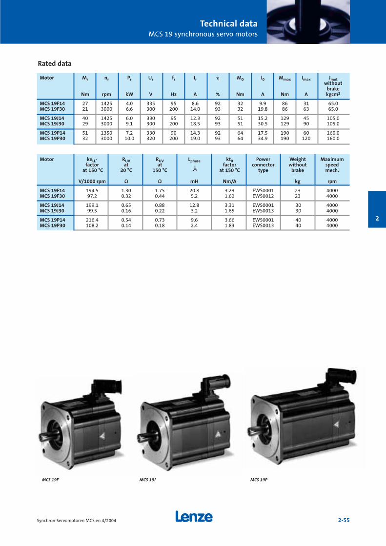
Technical dataMCS 19 synchronous servo motors
2-55Synchron-Servomotoren MCS en 4/2004
2
Rated data
Motor Mr nr Pr Ur fr Ir M0 I0 Mmax Imax Jmotwithout
brakeNm rpm kW V Hz A % Nm A Nm A kgcm2
MCS 19F14 27 1425 4.0 335 95 8.6 92 32 9.9 86 31 65.0MCS 19F30 21 3000 6.6 300 200 14.0 93 32 19.8 86 63 65.0
MCS 19J14 40 1425 6.0 330 95 12.3 92 51 15.2 129 45 105.0MCS 19J30 29 3000 9.1 300 200 18.5 93 51 30.5 129 90 105.0
MCS 19P14 51 1350 7.2 330 90 14.3 92 64 17.5 190 60 160.0MCS 19P30 32 3000 10.0 320 200 19.0 93 64 34.9 190 120 160.0
MCS 19JMCS 19F MCS 19P
Motor keLL- RUV RUV Lphase kt0 Power Weight Maximumfactor at at factor connector without speed
at 150 °C 20 °C 150 °C at 150 °C type brake mech.
V/1000 rpm Ω Ω mH Nm/A kg rpm
MCS 19F14 194.5 1.30 1.75 20.8 3.23 EWS0001 23 4000MCS 19F30 97.2 0.32 0.44 5.2 1.62 EWS0012 23 4000
MCS 19J14 199.1 0.65 0.88 12.8 3.31 EWS0001 30 4000MCS 19J30 99.5 0.16 0.22 3.2 1.65 EWS0013 30 4000
MCS 19P14 216.4 0.54 0.73 9.6 3.66 EWS0001 40 4000MCS 19P30 108.2 0.14 0.18 2.4 1.83 EWS0013 40 4000
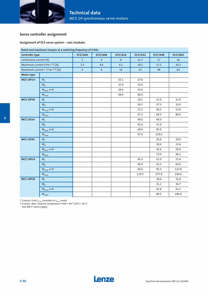
Technical dataMCS 19 synchronous servo motors
2-56 Synchron-Servomotoren MCS en 4/2004
2
Servo controller assignment
Assignment of ECS servo system – axis modules
Rated and maximum torques at a switching frequency of 4 kHz
Controller type ECSòA04 ECSòA08 ECSòA16 ECSòA32 ECSòA48 ECSòA64
Continuous current [A] 2 4 8 12.7 17 20
Maximum current 0 Hz 1) 2) [A] 2.3 4.6 9.1 18.1 27.2 36.3
Maximum current > 5 Hz 1) 2) [A] 4 8 16 32 48 64
Motor type
MCS 19F14 Mr 25.1 27.0
M0 25.9 32.0
Mmax n=0 28.6 54.6
Mmax 48.9 86.0
MCS 19F30 Mr 19.1 21.0 21.0
M0 20.5 27.5 32.0
Mmax n=0 27.2 40.5 53.0
Mmax 47.2 68.3 86.0
MCS 19J14 Mr 40.0 40.0
M0 42.6 51.0
Mmax n=0 58.9 85.0
Mmax 97.9 129.0
MCS 19J30 Mr 26.6 29.0
M0 28.4 33.4
Mmax n=0 42.6 56.9
Mmax 73.9 96.1
MCS 19P14 Mr 45.3 51.0 51.0
M0 46.4 62.2 64.0
Mmax n=0 64.6 95.3 123.8
Mmax 110.5 157.9 190.0
MCS 19P30 Mr 28.6 32.0
M0 31.2 36.7
Mmax n=0 45.8 61.1
Mmax 80.5 106.0
1) Caution: Limit Imax controller to Imax motor2) Caution: Max. heatsink temperature 9300 = 80 °C/ECS = 90 °C
and 400 V mains supply
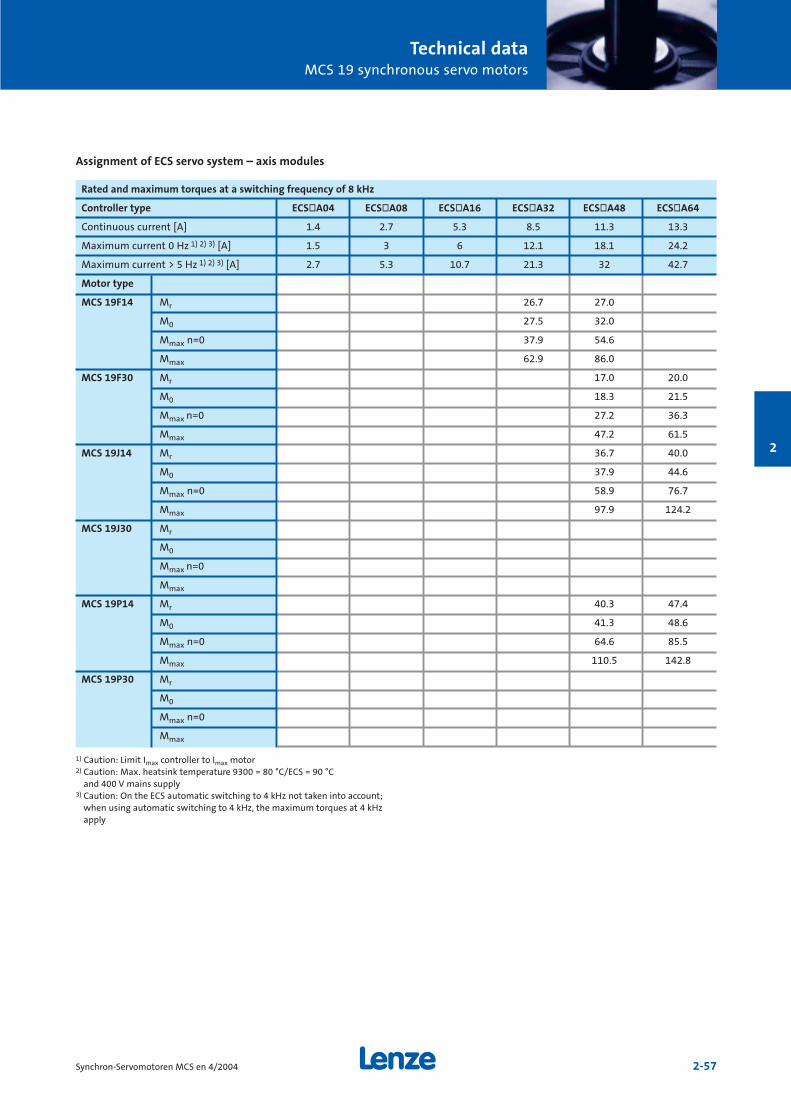
Technical dataMCS 19 synchronous servo motors
2-57Synchron-Servomotoren MCS en 4/2004
2
Rated and maximum torques at a switching frequency of 8 kHz
Controller type ECSòA04 ECSòA08 ECSòA16 ECSòA32 ECSòA48 ECSòA64
Continuous current [A] 1.4 2.7 5.3 8.5 11.3 13.3
Maximum current 0 Hz 1) 2) 3) [A] 1.5 3 6 12.1 18.1 24.2
Maximum current > 5 Hz 1) 2) 3) [A] 2.7 5.3 10.7 21.3 32 42.7
Motor type
MCS 19F14 Mr 26.7 27.0
M0 27.5 32.0
Mmax n=0 37.9 54.6
Mmax 62.9 86.0
MCS 19F30 Mr 17.0 20.0
M0 18.3 21.5
Mmax n=0 27.2 36.3
Mmax 47.2 61.5
MCS 19J14 Mr 36.7 40.0
M0 37.9 44.6
Mmax n=0 58.9 76.7
Mmax 97.9 124.2
MCS 19J30 Mr
M0
Mmax n=0
Mmax
MCS 19P14 Mr 40.3 47.4
M0 41.3 48.6
Mmax n=0 64.6 85.5
Mmax 110.5 142.8
MCS 19P30 Mr
M0
Mmax n=0
Mmax
1) Caution: Limit Imax controller to Imax motor2) Caution: Max. heatsink temperature 9300 = 80 °C/ECS = 90 °C
and 400 V mains supply3) Caution: On the ECS automatic switching to 4 kHz not taken into account;
when using automatic switching to 4 kHz, the maximum torques at 4 kHzapply
Assignment of ECS servo system – axis modules
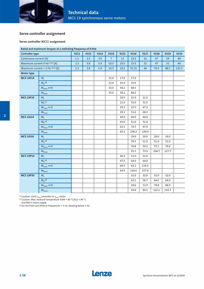
Technical dataMCS 19 synchronous servo motors
2-58 Synchron-Servomotoren MCS en 4/2004
2
Rated and maximum torques at a switching frequency of 8 kHz
Controller type 9321 9322 9323 9324 9325 9326 9327 9328 9329 9330
Continuous current [A] 1.5 2.5 3.9 7 13 23.5 32 47 59 89
Maximum current 0 Hz 1) 2) [A] 2.3 3.8 5.9 10.5 19.5 23.5 32 47 52 80
Maximum current > 5 Hz 1) 2) [A] 2.3 3.8 5.9 10.5 19.5 35.25 48 70.5 88.5 133.5
Motor type
MCS 19F14 Mr 22.0 27.0 27.0
M04) 22.6 32.0 32.0
Mmax n=0 33.0 58.2 68.3
Mmax 33.0 58.2 86.0
MCS 19F30 Mr 19.5 21.0 21.0
M04) 21.0 32.0 32.0
Mmax n=0 29.3 35.3 47.2
Mmax 29.3 51.6 68.3
MCS 19J14 Mr 40.0 40.0 40.0
M04) 43.6 51.0 51.0
Mmax n=0 63.1 74.7 97.9
Mmax 63.1 106.2 129.0
MCS 19J30 Mr 29.0 29.0 29.0 29.0
M04) 39.3 51.0 51.0 51.0
Mmax n=0 36.8 50.2 72.5 79.6
Mmax 55.3 73.9 104.7 127.7
MCS 19P14 Mr 46.4 51.0 51.0
M04) 47.5 64.0 64.0
Mmax n=0 69.5 83.2 110.5
Mmax 69.5 120.6 157.9
MCS 19P30 Mr 32.0 32.0 32.0 32.0
M04) 43.1 58.7 64.0 64.0
Mmax n=0 39.6 53.9 78.8 86.9
Mmax 59.4 80.5 116.1 143.7
1) Caution: Limit Imax controller to Imax motor2) Caution: Max. heatsink temperature 9300 = 80 °C/ECS = 90 °C
and 400 V mains supply4) On the 9329 and 9330 at frequencies > 5 Hz, derating below 5 Hz
Servo controller assignment
Servo controller 93òò assignment
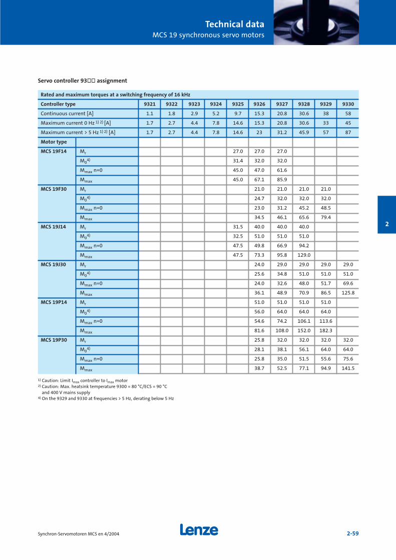
Technical dataMCS 19 synchronous servo motors
2-59Synchron-Servomotoren MCS en 4/2004
2
Rated and maximum torques at a switching frequency of 16 kHz
Controller type 9321 9322 9323 9324 9325 9326 9327 9328 9329 9330
Continuous current [A] 1.1 1.8 2.9 5.2 9.7 15.3 20.8 30.6 38 58
Maximum current 0 Hz 1) 2) [A] 1.7 2.7 4.4 7.8 14.6 15.3 20.8 30.6 33 45
Maximum current > 5 Hz 1) 2) [A] 1.7 2.7 4.4 7.8 14.6 23 31.2 45.9 57 87
Motor type
MCS 19F14 Mr 27.0 27.0 27.0
M04) 31.4 32.0 32.0
Mmax n=0 45.0 47.0 61.6
Mmax 45.0 67.1 85.9
MCS 19F30 Mr 21.0 21.0 21.0 21.0
M04) 24.7 32.0 32.0 32.0
Mmax n=0 23.0 31.2 45.2 48.5
Mmax 34.5 46.1 65.6 79.4
MCS 19J14 Mr 31.5 40.0 40.0 40.0
M04) 32.5 51.0 51.0 51.0
Mmax n=0 47.5 49.8 66.9 94.2
Mmax 47.5 73.3 95.8 129.0
MCS 19J30 Mr 24.0 29.0 29.0 29.0 29.0
M04) 25.6 34.8 51.0 51.0 51.0
Mmax n=0 24.0 32.6 48.0 51.7 69.6
Mmax 36.1 48.9 70.9 86.5 125.8
MCS 19P14 Mr 51.0 51.0 51.0 51.0
M04) 56.0 64.0 64.0 64.0
Mmax n=0 54.6 74.2 106.1 113.6
Mmax 81.6 108.0 152.0 182.3
MCS 19P30 Mr 25.8 32.0 32.0 32.0 32.0
M04) 28.1 38.1 56.1 64.0 64.0
Mmax n=0 25.8 35.0 51.5 55.6 75.6
Mmax 38.7 52.5 77.1 94.9 141.5
1) Caution: Limit Imax controller to Imax motor2) Caution: Max. heatsink temperature 9300 = 80 °C/ECS = 90 °C
and 400 V mains supply4) On the 9329 and 9330 at frequencies > 5 Hz, derating below 5 Hz
Servo controller 93òò assignment

Technical dataMCS 19 synchronous servo motors
2-60 Synchron-Servomotoren MCS en 4/2004
2
Torque characteristics
MCS 19F30
MCS 19F14
0
10
20
30
40
50
60
70
80
90
100
0 500 1000 1500 2000 2500 3000 3500 4000 4500
10
20
30
40
50
60
70
80
90
100
0 500 1000 1500 2000 25000
Continuous operation S1
Standstill torque: 32 Nm
Rated torque S1 operation: 21 Nm; 3000 rpm
Limit curve 360 V mains voltage
Limit curve 400 V mains voltage
Limit curve 440 V mains voltage
Max. torque (47.2 Nm) with ECSxA32 controller; Imax = 32.00 A, 4 kHz
Max. torque (68.3 Nm) with ECSxA48 controller; Imax = 48.00 A, 4 kHz
Max. torque (86 Nm) with ECSxA64 controller; Imax = 62.54 A, 4 kHz
Max. torque (47.2 Nm) with ECSxA48 controller; Imax = 32.00 A, 8 kHz
Max. torque (61.5 Nm) with ECSxA64 controller; Imax = 42.70 A, 8 kHz
Max. torque (34.5 Nm) with 9326 controller; Imax = 23.00 A, 16 kHz
Max. torque (46.1 Nm) with 9327 controller; Imax = 31.20 A, 16 kHz
Max. torque (65.6 Nm) with 9328 controller; Imax = 45.90 A, 16 kHz
Max. torque (79.4 Nm) with 9329 controller; Imax = 57.00 A, 16 kHz
Max. torque (29.3 Nm) with 9325 controller; Imax = 19.50 A, 8 kHz
Max. torque (51.6 Nm) with 9326 controller; Imax = 35.25 A, 8 kHz
Max. torque (68.3 Nm) with 9327 controller; Imax = 48.00 A, 8 kHz
Maximum and continuous torques
Torq
ue
[Nm
]
Speed [rpm]Maximum current of limit curve 63 A
Continuous operation S1
Standstill torque: 32 Nm
Rated torque S1 operation: 27 Nm; 1425 rpm
Limit curve 360 V mains voltage
Limit curve 400 V mains voltage
Limit curve 440 V mains voltage
Max. torque (48.9 Nm) with ECSxA16 controller; Imax = 16.00 A, 4 kHz
Max. torque (86 Nm) with ECSxA32 controller; Imax = 31.27 A, 4 kHz
Max. torque (62.8 Nm) with ECSxA32 controller; Imax = 21.30 A, 8 kHz
Max. torque (86 Nm) with ECSxA48 controller; Imax = 31.27 A, 8 kHz
Max. torque (24.5 Nm) with 9324 controller; Imax = 7.80 A, 16 kHz
Max. torque (45 Nm) with 9325 controller; Imax = 14.60 A, 16 kHz
Max. torque (67.1 Nm) with 9326 controller; Imax = 23.00 A, 16 kHz
Max. torque (85.8 Nm) with 9327 controller; Imax = 31.20 A, 16 kHz
Max. torque (33 Nm) with 9324 controller; Imax = 10.50 A, 8 kHz
Max. torque (58.2 Nm) with 9325 controller; Imax = 19.50 A, 8 kHz
Max. torque (86 Nm) with 9326 controller; Imax = 31.27 A, 8 kHz
Maximum and continuous torques
Torq
ue
[Nm
]
Speed [rpm]Maximum current of limit curve 31 A
At speeds < 75 rpm, servo controller derating may need to be taken intoaccount. See "Servo controller assignment" tables.
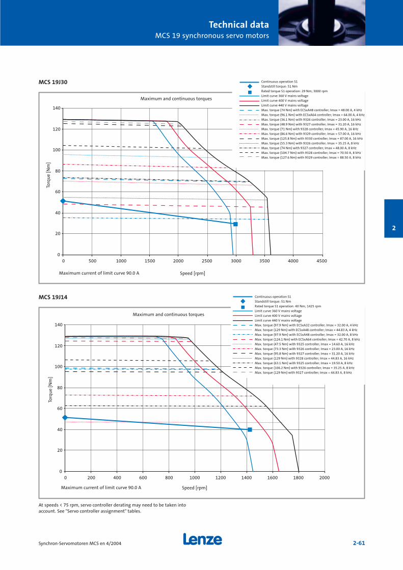
Technical dataMCS 19 synchronous servo motors
2-61Synchron-Servomotoren MCS en 4/2004
2
MCS 19J30
MCS 19J14
0
20
40
60
80
100
120
140
0 500 1000 1500 2000 2500 3000 3500 4000 4500
0
20
40
60
80
100
120
140
0 200 400 600 800 1000 1200 1400 1600 1800 2000
Continuous operation S1
Standstill torque: 51 Nm
Rated torque S1 operation: 29 Nm; 3000 rpm
Limit curve 360 V mains voltage
Limit curve 400 V mains voltage
Limit curve 440 V mains voltage
Max. torque (74 Nm) with ECSxA48 controller; Imax = 48.00 A, 4 kHz
Max. torque (96.1 Nm) with ECSxA64 controller; Imax = 64.00 A, 4 kHz
Max. torque (36.1 Nm) with 9326 controller; Imax = 23.00 A, 16 kHz
Max. torque (48.9 Nm) with 9327 controller; Imax = 31.20 A, 16 kHz
Max. torque (71 Nm) with 9328 controller; Imax = 45.90 A, 16 kHz
Max. torque (86.6 Nm) with 9329 controller; Imax = 57.00 A, 16 kHz
Max. torque (125.8 Nm) with 9330 controller; Imax = 87.00 A, 16 kHz
Max. torque (55.3 Nm) with 9326 controller; Imax = 35.25 A, 8 kHz
Max. torque (74 Nm) with 9327 controller; Imax = 48.00 A, 8 kHz
Max. torque (104.7 Nm) with 9328 controller; Imax = 70.50 A, 8 kHz
Max. torque (127.6 Nm) with 9329 controller; Imax = 88.50 A, 8 kHz
Continuous operation S1
Standstill torque: 51 Nm
Rated torque S1 operation: 40 Nm; 1425 rpm
Limit curve 360 V mains voltage
Limit curve 400 V mains voltage
Limit curve 440 V mains voltage
Max. torque (97.9 Nm) with ECSxA32 controller; Imax = 32.00 A, 4 kHz
Max. torque (129 Nm) with ECSxA48 controller; Imax = 44.83 A, 4 kHz
Max. torque (97.9 Nm) with ECSxA48 controller; Imax = 32.00 A, 8 kHz
Max. torque (124.1 Nm) with ECSxA64 controller; Imax = 42.70 A, 8 kHz
Max. torque (47.5 Nm) with 9325 controller; Imax = 14.60 A, 16 kHz
Max. torque (73.3 Nm) with 9326 controller; Imax = 23.00 A, 16 kHz
Max. torque (95.8 Nm) with 9327 controller; Imax = 31.20 A, 16 kHz
Max. torque (129 Nm) with 9328 controller; Imax = 44.83 A, 16 kHz
Max. torque (63.1 Nm) with 9325 controller; Imax = 19.50 A, 8 kHz
Max. torque (106.2 Nm) with 9326 controller; Imax = 35.25 A, 8 kHz
Max. torque (129 Nm) with 9327 controller; Imax = 44.83 A, 8 kHz
Torq
ue
[Nm
]
Speed [rpm]Maximum current of limit curve 90.0 A
Maximum and continuous torques
Torq
ue
[Nm
]
Speed [rpm]Maximum current of limit curve 90.0 A
Maximum and continuous torques
At speeds < 75 rpm, servo controller derating may need to be taken intoaccount. See "Servo controller assignment" tables.
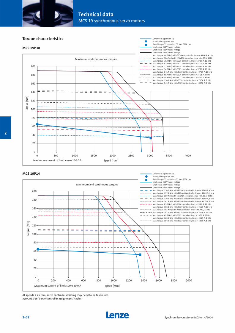
Technical dataMCS 19 synchronous servo motors
2-62 Synchron-Servomotoren MCS en 4/2004
2
Torque characteristics
MCS 19P30
MCS 19P14
0
20
40
60
80
100
120
140
160
180
200
0 500 1000 1500 2000 2500 3000 3500 4000
0
20
40
60
80
100
120
140
160
180
200
0 200 400 600 800 1000 1200 1400 1600 1800 2000
Continuous operation S1
Standstill torque: 64 Nm
Rated torque S1 operation: 32 Nm; 3000 rpm
Limit curve 360 V mains voltage
Limit curve 400 V mains voltage
Limit curve 440 V mains voltage
Max. torque (80.5 Nm) with ECSxA48 controller; Imax = 48.00 A, 4 kHz
Max. torque (106 Nm) with ECSxA64 controller; Imax = 64.00 A, 4 kHz
Max. torque (38.7 Nm) with 9326 controller; Imax = 23.00 A, 16 kHz
Max. torque (52.5 Nm) with 9327 controller; Imax = 31.20 A, 16 kHz
Max. torque (77.1 Nm) with 9328 controller; Imax = 45.90 A, 16 kHz
Max. torque (94.9 Nm) with 9329 controller; Imax = 57.00 A, 16 kHz
Max. torque (141.4 Nm) with 9330 controller; Imax = 87.00 A, 16 kHz
Max. torque (59.4 Nm) with 9326 controller; Imax = 35.25 A, 8 kHz
Max. torque (80.5 Nm) with 9327 controller; Imax = 48.00 A, 8 kHz
Max. torque (116.1 Nm) with 9328 controller; Imax = 70.50 A, 8 kHz
Max. torque (143.7 Nm) with 9329 controller; Imax = 88.50 A, 8 kHz
Maximum and continuous torques
Torq
ue
[Nm
]
Speed [rpm]Maximum current of limit curve 120.0 A
Continuous operation S1
Standstill torque: 64 Nm
Rated torque S1 operation: 51 Nm; 1350 rpm
Limit curve 360 V mains voltage
Limit curve 400 V mains voltage
Limit curve 440 V mains voltage
Max. torque (110.6 Nm) with ECSxA32 controller; Imax = 32.00 A, 4 kHz
Max. torque (157.9 Nm) with ECSxA48 controller; Imax = 48.00 A, 4 kHz
Max. torque (190 Nm) with ECSxA64 controller; Imax = 60.00 A, 4 kHz
Max. torque (110.6 Nm) with ECSxA48 controller; Imax = 32.00 A, 8 kHz
Max. torque (142.8 Nm) with ECSxA64 controller; Imax = 42.70 A, 8 kHz
Max. torque (81.6 Nm) with 9326 controller; Imax = 23.00 A, 16 kHz
Max. torque (108.1 Nm) with 9327 controller; Imax = 31.20 A, 16 kHz
Max. torque (152 Nm) with 9328 controller; Imax = 45.90 A, 16 kHz
Max. torque (182.2 Nm) with 9329 controller; Imax = 57.00 A, 16 kHz
Max. torque (69.5 Nm) with 9325 controller; Imax = 19.50 A, 8 kHz
Max. torque (120.6 Nm) with 9326 controller; Imax = 35.25 A, 8 kHz
Max. torque (157.9 Nm) with 9327 controller; Imax = 48.00 A, 8 kHz
Maximum and continuous torques
Torq
ue
[Nm
]
Speed [rpm]Maximum current of limit curve 60.0 A
At speeds < 75 rpm, servo controller derating may need to be taken intoaccount. See "Servo controller assignment" tables.
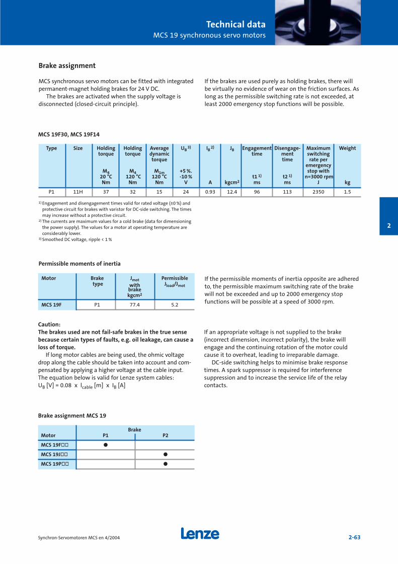
Technical dataMCS 19 synchronous servo motors
2-63Synchron-Servomotoren MCS en 4/2004
2
MCS 19F30, MCS 19F14
1) Engagement and disengagement times valid for rated voltage (±0 %) andprotective circuit for brakes with varistor for DC-side switching. The timesmay increase without a protective circuit.
2) The currents are maximum values for a cold brake (data for dimensioningthe power supply). The values for a motor at operating temperature areconsiderably lower.
3) Smoothed DC voltage, ripple < 1 %
If the permissible moments of inertia opposite are adheredto, the permissible maximum switching rate of the brakewill not be exceeded and up to 2000 emergency stop functions will be possible at a speed of 3000 rpm.
Motor Brake Jmot Permissibletype with Jload/Jmot
brakekgcm2
MCS 19F P1 77.4 5.2
Permissible moments of inertia
Type Size Holding Holding Average UB3) IB
2) JB Engagement Disengage- Maximum Weighttorque torque dynamic time ment switching
torque time rate peremergency
M4 M4 M1m +5 %. stop with20 °C 120 °C 120 °C -10 % t1 1) t2 1) n=3000 rpmNm Nm Nm V A kgcm2 ms ms J kg
P1 11H 37 32 15 24 0.93 12.4 96 113 2350 1.5
Brake assignment
MCS synchronous servo motors can be fitted with integratedpermanent-magnet holding brakes for 24 V DC.
The brakes are activated when the supply voltage is disconnected (closed-circuit principle).
If the brakes are used purely as holding brakes, there willbe virtually no evidence of wear on the friction surfaces. Aslong as the permissible switching rate is not exceeded, atleast 2000 emergency stop functions will be possible.
Caution:The brakes used are not fail-safe brakes in the true sensebecause certain types of faults, e.g. oil leakage, can cause aloss of torque.
If long motor cables are being used, the ohmic voltagedrop along the cable should be taken into account and com-pensated by applying a higher voltage at the cable input.The equation below is valid for Lenze system cables: UB [V] = 0.08 x lcable [m] x IB [A]
If an appropriate voltage is not supplied to the brake (incorrect dimension, incorrect polarity), the brake willengage and the continuing rotation of the motor couldcause it to overheat, leading to irreparable damage.
DC-side switching helps to minimise brake responsetimes. A spark suppressor is required for interference suppression and to increase the service life of the relaycontacts.
BrakeMotor P1 P2
MCS 19Fòò ö
MCS 19Jòò ö
MCS 19Pòò ö
Brake assignment MCS 19
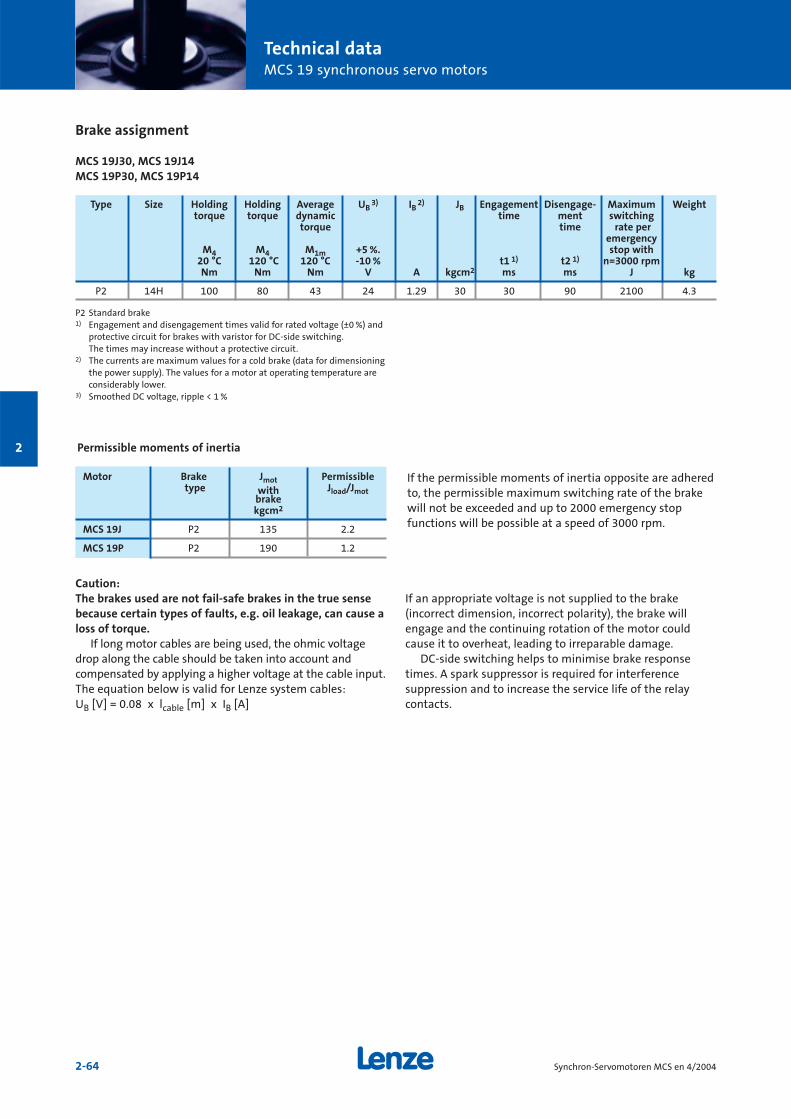
Technical dataMCS 19 synchronous servo motors
2-64 Synchron-Servomotoren MCS en 4/2004
2
Brake assignment
MCS 19J30, MCS 19J14MCS 19P30, MCS 19P14
P2 Standard brake1) Engagement and disengagement times valid for rated voltage (±0 %) and
protective circuit for brakes with varistor for DC-side switching. The times may increase without a protective circuit.
2) The currents are maximum values for a cold brake (data for dimensioningthe power supply). The values for a motor at operating temperature areconsiderably lower.
3) Smoothed DC voltage, ripple < 1 %
If the permissible moments of inertia opposite are adheredto, the permissible maximum switching rate of the brakewill not be exceeded and up to 2000 emergency stop functions will be possible at a speed of 3000 rpm.
Motor Brake Jmot Permissibletype with Jload/Jmot
brakekgcm2
MCS 19J P2 135 2.2
MCS 19P P2 190 1.2
Permissible moments of inertia
Type Size Holding Holding Average UB3) IB
2) JB Engagement Disengage- Maximum Weighttorque torque dynamic time ment switching
torque time rate peremergency
M4 M4 M1m +5 %. stop with 20 °C 120 °C 120 °C -10 % t1 1) t2 1) n=3000 rpmNm Nm Nm V A kgcm2 ms ms J kg
P2 14H 100 80 43 24 1.29 30 30 90 2100 4.3
Caution:The brakes used are not fail-safe brakes in the true sensebecause certain types of faults, e.g. oil leakage, can cause aloss of torque.
If long motor cables are being used, the ohmic voltagedrop along the cable should be taken into account and compensated by applying a higher voltage at the cable input.The equation below is valid for Lenze system cables: UB [V] = 0.08 x lcable [m] x IB [A]
If an appropriate voltage is not supplied to the brake (incorrect dimension, incorrect polarity), the brake willengage and the continuing rotation of the motor couldcause it to overheat, leading to irreparable damage.
DC-side switching helps to minimise brake responsetimes. A spark suppressor is required for interference suppression and to increase the service life of the relaycontacts.
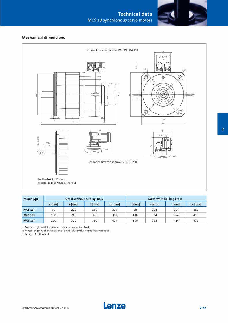
Technical dataMCS 19 synchronous servo motors
2-65Synchron-Servomotoren MCS en 4/2004
2
Mechanical dimensions
36
l Motor length with installation of a resolver as feedbacklx Motor length with installation of an absolute value encoder as feedbacki Length of coil module
Motor type Motor without holding brake Motor with holding brake
i [mm] k [mm] l [mm] lx [mm] i [mm] k [mm] l [mm] lx [mm]
MCS 19F 60 220 280 329 60 254 314 363
MCS 19J 100 260 320 369 100 304 364 413
MCS 19P 160 320 380 429 160 364 424 473
Connector dimensions on MCS 19F, J14, P14
Connector dimensions on MCS 19J30, P30
Featherkey 8 x 50 mm(according to DIN 6885, sheet 1)

Technical dataMCS 19 synchronous servo motors
2-66 Synchron-Servomotoren MCS en 4/2004
2
Permissible shaft loads
Forces on the motor shaft
The following diagrams provide a simple means of determi-ning: a) The maximum permissible radial force along with the
corresponding maximum permissible torsional momenton the motor shaft.
b) The service life of the roller bearings on the basis of theforces and torques calculated.
Service life is calculated as follows:No. of bearing revolutions
= Bearing service life [h]n [rpm] x 60
The characteristics are valid for all MCS 19 frame sizes
0
50
100
150
200
250
0 500 1000 1500 2000 2500 3000 3500 4000 4500 5000
Relationship between radial force and torsional moment onshaft
Without featherkeyTa=f (Fr1) force appliedcentre of shaft journal Without featherkeyTa=f (Fr2) force appliedend of shaft journalWith featherkeyTa=f (Fr1) force appliedcentre of shaft journalWith featherkeyTa=f (Fr2) force appliedend of shaft journal
Radial force Fr [N]
Tors
ion
al m
omen
tT a
[Nm
]

Technical dataMCS 19 synchronous servo motors
2-67Synchron-Servomotoren MCS en 4/2004
2
0
500
1000
1500
2000
2500
3000
3500
4000
4500
5000
-3000 -2500 -2000 -1500 -1000 -500 0 500 1000 1500 2000
-1000
Permissible radial force Fr1 and axial force Fa on shaft
-1000
0
1000
2000
3000
4000
5000
-3000 -2000 -1000 0 1000 2000
Permissible radial force Fr2 and axial force Fa on shaft
1000
10000
100000
1000000
0 500 1000 1500 2000 2500 3000 3500 4000 4500
Relationship between the number of total bearing revolutions, bearing service life and the average speed ofthe drive
1.2E09 revolutions(5000 h at 4000 rpm)2.4E09 revolutions(10000 h at 4000 rpm)4.8E09 revolutions(20000 h at 4000 rpm)7.2E09 revolutions(30000 h at 4000 rpm)1.2E10 revolutions(50000 h at 4000 rpm)
1.2E09 revolutions(5000 h at 4000 rpm)2.4E09 revolutions(10000 h at 4000 rpm)4.8E09 revolutions(20000 h at 4000 rpm)7.2E09 revolutions(30000 h at 4000 rpm)1.2E10 revolutions(50000 h at 4000 rpm)
1.2E+09 revolutions2.4E+09 revolutions4.8E+09 revolutions7.2E+09 revolutions1.2E+10 revolutions
Axial force Fa [N]
Rad
ial f
orce
Fr1
[N]
Axial force Fa [N]
Rad
ial f
orce
Fr2
[N]
Speed n [rpm]
Bea
rin
g op
erat
ing
tim
e t
[h]
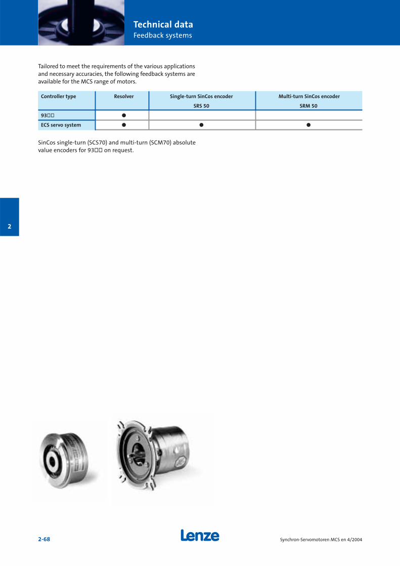
Technical dataFeedback systems
2-68 Synchron-Servomotoren MCS en 4/2004
2
Tailored to meet the requirements of the various applicationsand necessary accuracies, the following feedback systems areavailable for the MCS range of motors.
Controller type Resolver Single-turn SinCos encoder Multi-turn SinCos encoder
SRS 50 SRM 50
93òò ö
ECS servo system ö ö ö
SinCos single-turn (SCS70) and multi-turn (SCM70) absolutevalue encoders for 93òò on request.
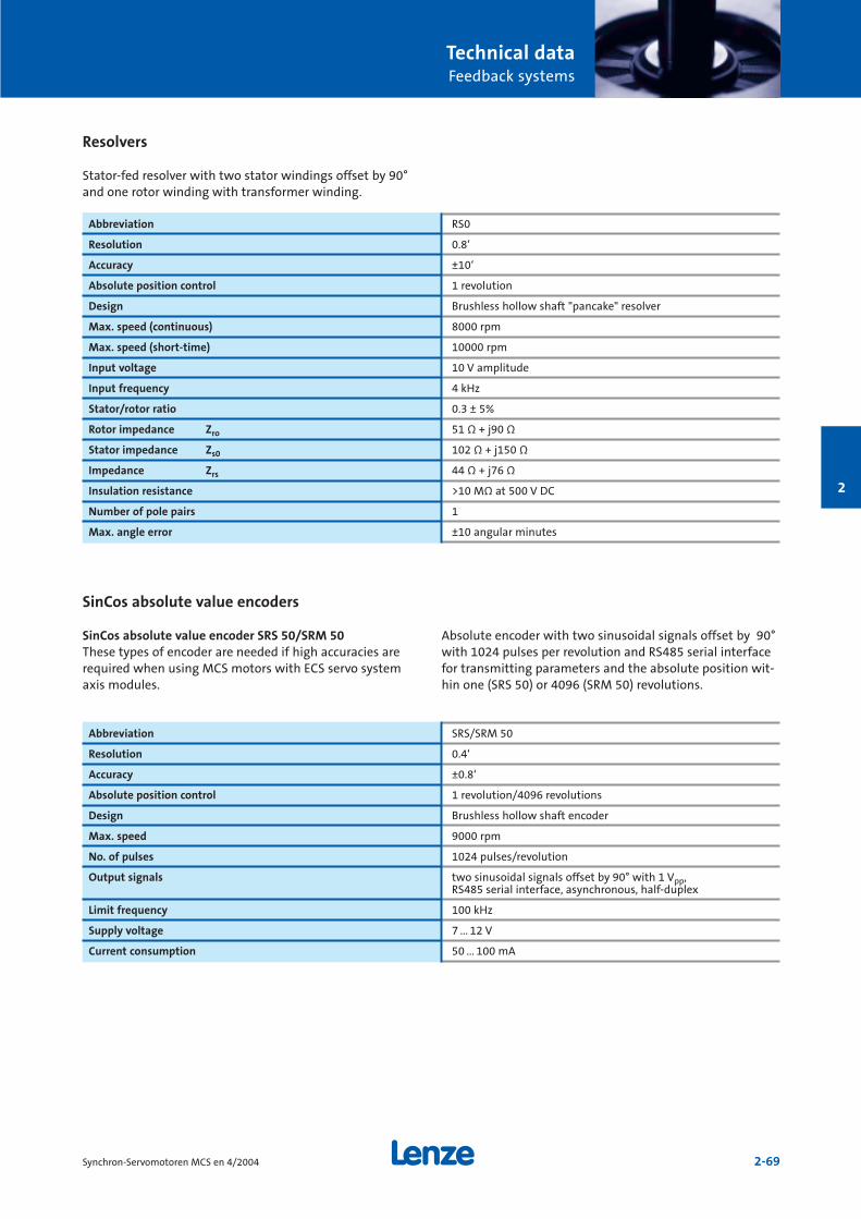
Technical dataFeedback systems
2-69Synchron-Servomotoren MCS en 4/2004
2
Resolvers
Stator-fed resolver with two stator windings offset by 90°and one rotor winding with transformer winding.
Abbreviation RS0
Resolution 0.8‘
Accuracy ±10‘
Absolute position control 1 revolution
Design Brushless hollow shaft "pancake" resolver
Max. speed (continuous) 8000 rpm
Max. speed (short-time) 10000 rpm
Input voltage 10 V amplitude
Input frequency 4 kHz
Stator/rotor ratio 0.3 ± 5%
Rotor impedance Zro 51 Ω + j90 Ω
Stator impedance Zs0 102 Ω + j150 Ω
Impedance Zrs 44 Ω + j76 Ω
Insulation resistance >10 MΩ at 500 V DC
Number of pole pairs 1
Max. angle error ±10 angular minutes
SinCos absolute value encoders
SinCos absolute value encoder SRS 50/SRM 50These types of encoder are needed if high accuracies arerequired when using MCS motors with ECS servo systemaxis modules.
Absolute encoder with two sinusoidal signals offset by 90°with 1024 pulses per revolution and RS485 serial interfacefor transmitting parameters and the absolute position wit-hin one (SRS 50) or 4096 (SRM 50) revolutions.
Abbreviation SRS/SRM 50
Resolution 0.4‘
Accuracy ±0.8‘
Absolute position control 1 revolution/4096 revolutions
Design Brushless hollow shaft encoder
Max. speed 9000 rpm
No. of pulses 1024 pulses/revolution
Output signals two sinusoidal signals offset by 90° with 1 Vpp, RS485 serial interface, asynchronous, half-duplex
Limit frequency 100 kHz
Supply voltage 7 ... 12 V
Current consumption 50 ... 100 mA

Technical dataTemperature sensors
2-70 Synchron-Servomotoren MCS en 4/2004
2
The temperature sensors used in the MCS motors ensurethe absolute and reliable detection of excess winding tem-peratures on every type of motor and in every operationalsituation. The temperature information is transmitted tothe servo controller via the feedback system's system cable.Due to differing physical conditions, MCS motors featuretwo different types of temperature monitoring mechanism:
MCS 06On this motor, the winding temperature of a winding phaseis monitored using a KTY 83-110 type temperature sensor.In addition, the overall motor temperature is determined/monitored using a temperature model in the connectedcontroller. This calculation model, which has been designedspecifically for this motor, also ensures that the overtem-perature response configured in the controller will betriggered reliably and in good time should excess tempera-tures occur in winding phases not monitored by the KTY.
MCS 09-MCS 19These motors are monitored using three temperature sensors connected in series (1x KTY 83-110 + 2xPTC 150 °C).This ensures that the temperature of the motor can bedetected with a high degree of accuracy in the permittedoperating range and that the overtemperature response configured in the controller will be triggered reliably and ingood time should an overtemperature occur in one of thewinding phases.
If the detector is supplied with a measured current of 1 mA,the above relationship between the temperature and theresistance applies.
1000
1200
1400
1600
1800
2000
2200
2400
2600
2800
3000
0 20 40 60 80 100 120 140 160 180
Note: To ensure trouble-free operation, the temperature sensormust be connected to the servo controller with the correctpolarity.
Temperature sensors characteristic
Resi
stan
ce [o
hm
s]
Temperature [°C] MCS09...19 (KTY 83-110 + 2 x PTC150°C)
MCS06 (KTY 83-110)
2-71Synchron-Servomotoren MCS en 4/2004
2
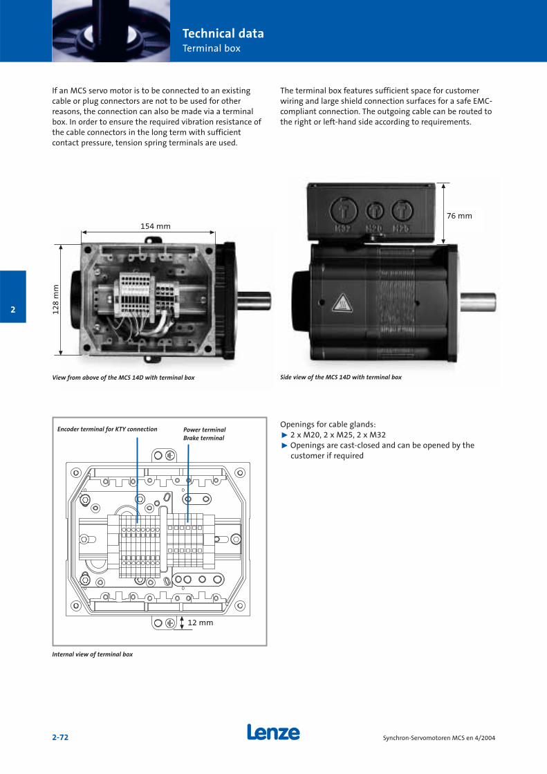
Technical dataTerminal box
2-72 Synchron-Servomotoren MCS en 4/2004
2
If an MCS servo motor is to be connected to an existingcable or plug connectors are not to be used for other reasons, the connection can also be made via a terminalbox. In order to ensure the required vibration resistance ofthe cable connectors in the long term with sufficientcontact pressure, tension spring terminals are used.
The terminal box features sufficient space for customerwiring and large shield connection surfaces for a safe EMC-compliant connection. The outgoing cable can be routed tothe right or left-hand side according to requirements.
Encoder terminal for KTY connection Power terminalBrake terminal
Internal view of terminal box
Openings for cable glands:˘ 2 x M20, 2 x M25, 2 x M32˘ Openings are cast-closed and can be opened by the
customer if required
76 mm154 mm
128
mm
◊
◊
◊
◊
View from above of the MCS 14D with terminal box
◊
◊
Side view of the MCS 14D with terminal box
12 mm
◊
◊
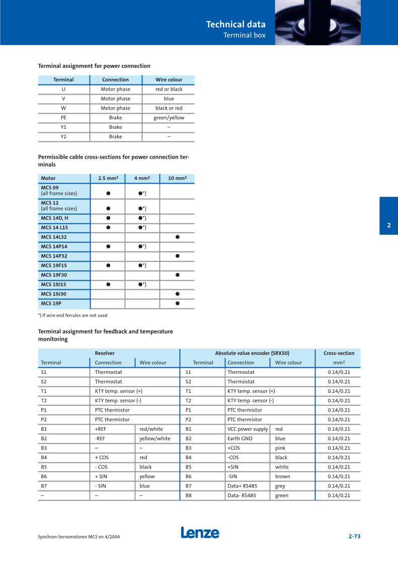
Technical dataTerminal box
2-73Synchron-Servomotoren MCS en 4/2004
2
Terminal assignment for power connection
Permissible cable cross-sections for power connection ter-minals
Terminal Connection Wire colour
U Motor phase red or black
V Motor phase blue
W Motor phase black or red
PE Brake green/yellow
Y1 Brake –
Y2 Brake –
Motor 2.5 mm2 4 mm2 10 mm2
MCS 09 (all frame sizes) ö ö*)
MCS 12(all frame sizes) ö ö*)
MCS 14D, H ö ö*)
MCS 14 L15 ö ö*)
MCS 14L32 ö
MCS 14P14 ö ö*)
MCS 14P32 ö
MCS 19F15 ö ö*)
MCS 19F30 ö
MCS 19J15 ö ö*)
MCS 19J30 ö
MCS 19P ö
Terminal assignment for feedback and temperature monitoring
Resolver Absolute value encoder (SRX50) Cross-section
Terminal Connection Wire colour Terminal Connection Wire colour mm2
S1 Thermostat S1 Thermostat 0.14/0.21
S2 Thermostat S2 Thermostat 0.14/0.21
T1 KTY temp. sensor (+) T1 KTY temp. sensor (+) 0.14/0.21
T2 KTY temp. sensor (-) T2 KTY temp. sensor (-) 0.14/0.21
P1 PTC thermistor P1 PTC thermistor 0.14/0.21
P2 PTC thermistor P2 PTC thermistor 0.14/0.21
B1 +REF red/white B1 VCC power supply red 0.14/0.21
B2 -REF yellow/white B2 Earth GND blue 0.14/0.21
B3 – – B3 +COS pink 0.14/0.21
B4 + COS red B4 -COS black 0.14/0.21
B5 - COS black B5 +SIN white 0.14/0.21
B6 + SIN yellow B6 -SIN brown 0.14/0.21
B7 - SIN blue B7 Data+ RS485 grey 0.14/0.21
– – – B8 Data- RS485 green 0.14/0.21
*) If wire end ferrules are not used
3-1Synchron-Servomotoren MCS en 4/2004
Accessories MCS synchronous servo motors
Motor cables3-2
Overview ofsystem cables
3-5
Resolver andencoder cables
3-6
System connectors3-8
3
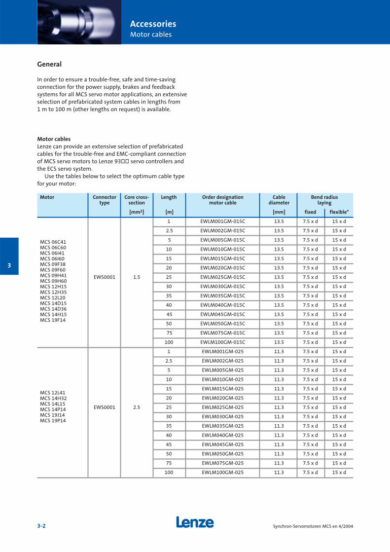
AccessoriesMotor cables
3-2 Synchron-Servomotoren MCS en 4/2004
3
General
In order to ensure a trouble-free, safe and time-savingconnection for the power supply, brakes and feedbacksystems for all MCS servo motor applications, an extensiveselection of prefabricated system cables in lengths from1 m to 100 m (other lengths on request) is available.
Motor cablesLenze can provide an extensive selection of prefabricatedcables for the trouble-free and EMC-compliant connectionof MCS servo motors to Lenze 93òò servo controllers andthe ECS servo system.
Use the tables below to select the optimum cable typefor your motor:
Motor Connector Core cross- Length Order designation Cable Bend radiustype section motor cable diameter laying
[mm2] [m] [mm] fixed flexible*
1 EWLM001GM-015C 13.5 7.5 x d 15 x d
2.5 EWLM002GM-015C 13.5 7.5 x d 15 x d
5 EWLM005GM-015C 13.5 7.5 x d 15 x d
10 EWLM010GM-015C 13.5 7.5 x d 15 x d
15 EWLM015GM-015C 13.5 7.5 x d 15 x d
20 EWLM020GM-015C 13.5 7.5 x d 15 x d
EWS0001 1.5 25 EWLM025GM-015C 13.5 7.5 x d 15 x d
30 EWLM030GM-015C 13.5 7.5 x d 15 x d
35 EWLM035GM-015C 13.5 7.5 x d 15 x d
40 EWLM040GM-015C 13.5 7.5 x d 15 x d
45 EWLM045GM-015C 13.5 7.5 x d 15 x d
50 EWLM050GM-015C 13.5 7.5 x d 15 x d
75 EWLM075GM-015C 13.5 7.5 x d 15 x d
100 EWLM100GM-015C 13.5 7.5 x d 15 x d
1 EWLM001GM-025 11.3 7.5 x d 15 x d
2.5 EWLM002GM-025 11.3 7.5 x d 15 x d
5 EWLM005GM-025 11.3 7.5 x d 15 x d
10 EWLM010GM-025 11.3 7.5 x d 15 x d
15 EWLM015GM-025 11.3 7.5 x d 15 x d
20 EWLM020GM-025 11.3 7.5 x d 15 x d
EWS0001 2.5 25 EWLM025GM-025 11.3 7.5 x d 15 x d
30 EWLM030GM-025 11.3 7.5 x d 15 x d
35 EWLM035GM-025 11.3 7.5 x d 15 x d
40 EWLM040GM-025 11.3 7.5 x d 15 x d
45 EWLM045GM-025 11.3 7.5 x d 15 x d
50 EWLM050GM-025 11.3 7.5 x d 15 x d
75 EWLM075GM-025 11.3 7.5 x d 15 x d
100 EWLM100GM-025 11.3 7.5 x d 15 x d
MCS 06C41MCS 06C60MCS 06I41MCS 06I60MCS 09F38MCS 09F60MCS 09H41MCS 09H60MCS 12H15MCS 12H35MCS 12L20MCS 14D15MCS 14D36MCS 14H15MCS 19F14
MCS 12L41MCS 14H32MCS 14L15MCS 14P14MCS 19J14MCS 19P14
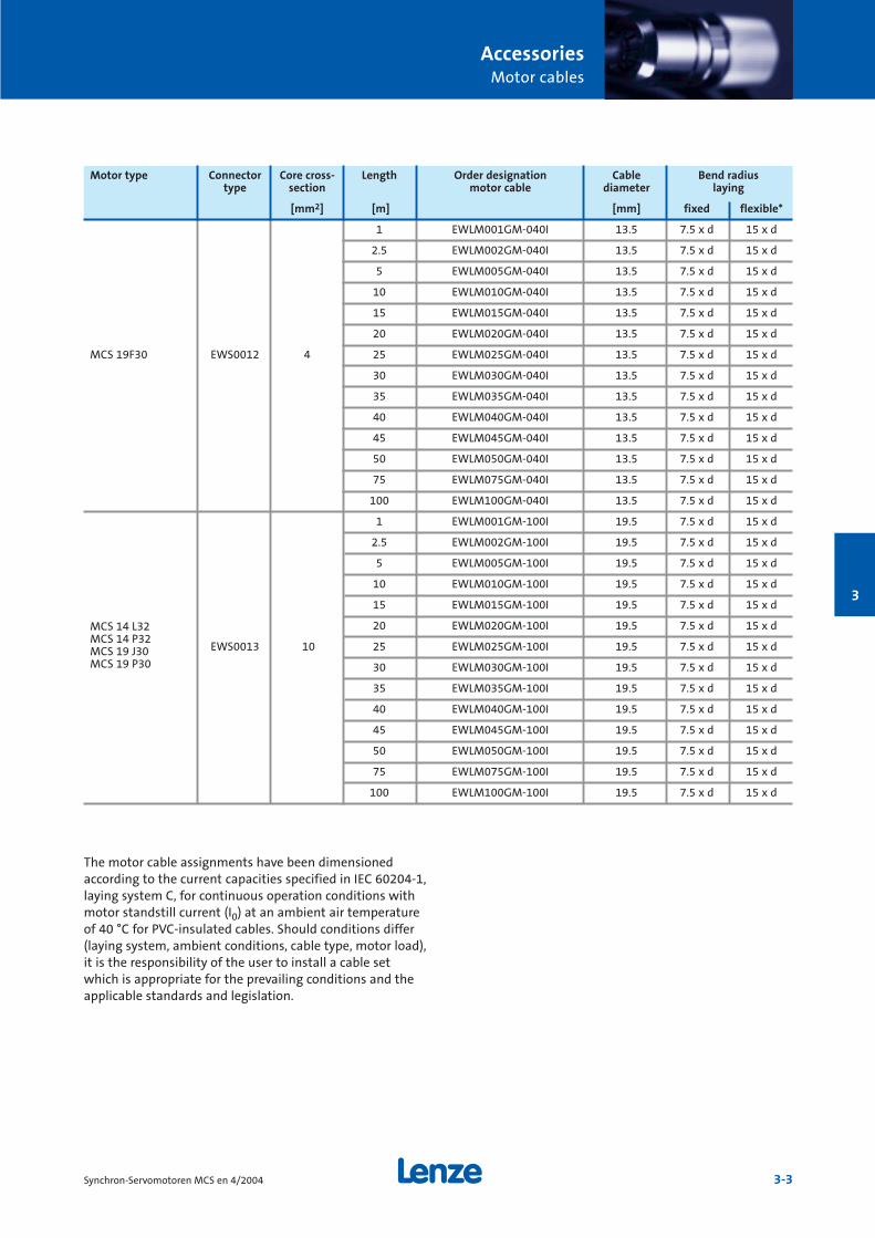
AccessoriesMotor cables
3-3Synchron-Servomotoren MCS en 4/2004
3
Motor type Connector Core cross- Length Order designation Cable Bend radiustype section motor cable diameter laying
[mm2] [m] [mm] fixed flexible*
1 EWLM001GM-040I 13.5 7.5 x d 15 x d
2.5 EWLM002GM-040I 13.5 7.5 x d 15 x d
5 EWLM005GM-040I 13.5 7.5 x d 15 x d
10 EWLM010GM-040I 13.5 7.5 x d 15 x d
15 EWLM015GM-040I 13.5 7.5 x d 15 x d
20 EWLM020GM-040I 13.5 7.5 x d 15 x d
MCS 19F30 EWS0012 4 25 EWLM025GM-040I 13.5 7.5 x d 15 x d
30 EWLM030GM-040I 13.5 7.5 x d 15 x d
35 EWLM035GM-040I 13.5 7.5 x d 15 x d
40 EWLM040GM-040I 13.5 7.5 x d 15 x d
45 EWLM045GM-040I 13.5 7.5 x d 15 x d
50 EWLM050GM-040I 13.5 7.5 x d 15 x d
75 EWLM075GM-040I 13.5 7.5 x d 15 x d
100 EWLM100GM-040I 13.5 7.5 x d 15 x d
1 EWLM001GM-100I 19.5 7.5 x d 15 x d
2.5 EWLM002GM-100I 19.5 7.5 x d 15 x d
5 EWLM005GM-100I 19.5 7.5 x d 15 x d
10 EWLM010GM-100I 19.5 7.5 x d 15 x d
15 EWLM015GM-100I 19.5 7.5 x d 15 x d
20 EWLM020GM-100I 19.5 7.5 x d 15 x d
EWS0013 10 25 EWLM025GM-100I 19.5 7.5 x d 15 x d
30 EWLM030GM-100I 19.5 7.5 x d 15 x d
35 EWLM035GM-100I 19.5 7.5 x d 15 x d
40 EWLM040GM-100I 19.5 7.5 x d 15 x d
45 EWLM045GM-100I 19.5 7.5 x d 15 x d
50 EWLM050GM-100I 19.5 7.5 x d 15 x d
75 EWLM075GM-100I 19.5 7.5 x d 15 x d
100 EWLM100GM-100I 19.5 7.5 x d 15 x d
The motor cable assignments have been dimensionedaccording to the current capacities specified in IEC 60204-1,laying system C, for continuous operation conditions withmotor standstill current (I0) at an ambient air temperatureof 40 °C for PVC-insulated cables. Should conditions differ(laying system, ambient conditions, cable type, motor load),it is the responsibility of the user to install a cable setwhich is appropriate for the prevailing conditions and theapplicable standards and legislation.
MCS 14 L32MCS 14 P32MCS 19 J30MCS 19 P30
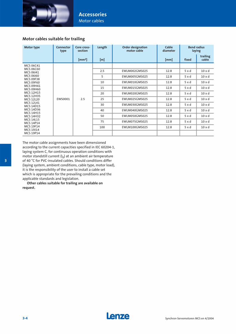
AccessoriesMotor cables
3-4 Synchron-Servomotoren MCS en 4/2004
3
Motor cables suitable for trailing
Motor type Connector Core cross- Length Order designation Cable Bend radiustype section motor cable diameter laying
trailing[mm2] [m] [mm] fixed cable
2.5 EWLM002GMS025 12.8 5 x d 10 x d
5 EWLM005GMS025 12.8 5 x d 10 x d
10 EWLM010GMS025 12.8 5 x d 10 x d
15 EWLM015GMS025 12.8 5 x d 10 x d
20 EWLM020GMS025 12.8 5 x d 10 x d
EWS0001 2.5 25 EWLM025GMS025 12.8 5 x d 10 x d
30 EWLM030GMS025 12.8 5 x d 10 x d
40 EWLM040GMS025 12.8 5 x d 10 x d
50 EWLM050GMS025 12.8 5 x d 10 x d
75 EWLM075GMS025 12.8 5 x d 10 x d
100 EWLM100GMS025 12.8 5 x d 10 x d
The motor cable assignments have been dimensionedaccording to the current capacities specified in IEC 60204-1,laying system C, for continuous operation conditions withmotor standstill current (I0) at an ambient air temperatureof 40 °C for PVC-insulated cables. Should conditions differ(laying system, ambient conditions, cable type, motor load),it is the responsibility of the user to install a cable setwhich is appropriate for the prevailing conditions and theapplicable standards and legislation.
Other cables suitable for trailing are available onrequest.
MCS 06C41MCS 06C60MCS 06I41MCS 06I60MCS 09F38MCS 09F60MCS 09H41MCS 09H60MCS 12H15MCS 12H35MCS 12L20MCS 12L41MCS 14D15MCS 14D36MCS 14H15MCS 14H32MCS 14L15MCS 14P14MCS 19F14MCS 19J14MCS 19P14
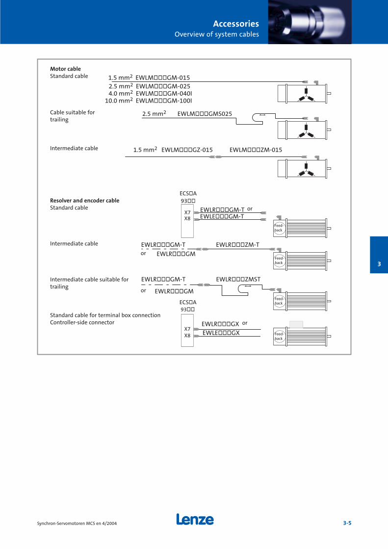
AccessoriesOverview of system cables
3-5Synchron-Servomotoren MCS en 4/2004
3
MotorleitungStandardleitung 1.5 mm2 EWLMòòòGM-015
2.5 mm2 EWLMòòòGM-025 4.0 mm2 EWLMòòòGM-040I 10.0 mm2 EWLMòòòGM-100I
Schleppkettentaugliche 2.5 mm2 EWLMòòòGMS025Leitung
Zwischenleitung 1.5 mm2 EWLMòòòGZ-015 EWLMòòòZM-015
Resolver- und EncoderleitungStandardleitung EWLRòòòGM-T oder
EWLEòòòGM-T
Zwischenleitung EWLRòòòGM-T EWLRòòòZM-T
oder EWLRòòòGM
Schleppkettentaugliche EWLRòòòGM-T EWLRòòòZMSTZwischenleitung
Standardleitung Klemmkastenanschluss Stecker geräteseitig EWLRòòòGX oder
EWLEòòòGX
93òò
X7
Feed-back
Feed-back
93òò
X7Feed-back
X8
X8
Feed-back
oder EWLRòòòGM
ECSòA
ECSòA
Resolver and encoder cableStandard cable
Intermediate cable
Intermediate cable suitable fortrailing
Cable suitable fortrailing
Intermediate cable
Motor cableStandard cable
Standard cable for terminal box connectionController-side connector
or
or
or
or
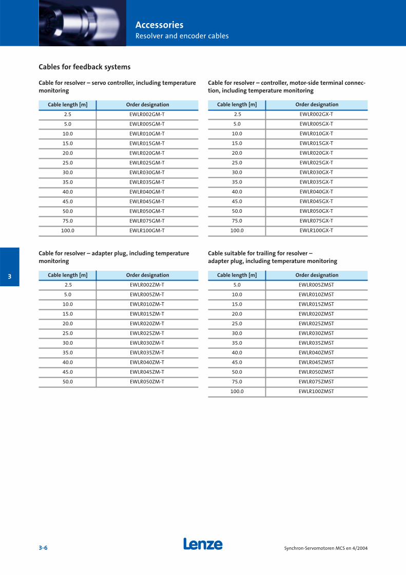
AccessoriesResolver and encoder cables
3-6 Synchron-Servomotoren MCS en 4/2004
3
Cable for resolver – controller, motor-side terminal connec-tion, including temperature monitoring
Cable length [m] Order designation
2.5 EWLR002GX-T
5.0 EWLR005GX-T
10.0 EWLR010GX-T
15.0 EWLR015GX-T
20.0 EWLR020GX-T
25.0 EWLR025GX-T
30.0 EWLR030GX-T
35.0 EWLR035GX-T
40.0 EWLR040GX-T
45.0 EWLR045GX-T
50.0 EWLR050GX-T
75.0 EWLR075GX-T
100.0 EWLR100GX-T
Cables for feedback systems
Cable for resolver – servo controller, including temperaturemonitoring
Cable length [m] Order designation
2.5 EWLR002GM-T
5.0 EWLR005GM-T
10.0 EWLR010GM-T
15.0 EWLR015GM-T
20.0 EWLR020GM-T
25.0 EWLR025GM-T
30.0 EWLR030GM-T
35.0 EWLR035GM-T
40.0 EWLR040GM-T
45.0 EWLR045GM-T
50.0 EWLR050GM-T
75.0 EWLR075GM-T
100.0 EWLR100GM-T
Cable for resolver – adapter plug, including temperaturemonitoring
Cable length [m] Order designation
2.5 EWLR002ZM-T
5.0 EWLR005ZM-T
10.0 EWLR010ZM-T
15.0 EWLR015ZM-T
20.0 EWLR020ZM-T
25.0 EWLR025ZM-T
30.0 EWLR030ZM-T
35.0 EWLR035ZM-T
40.0 EWLR040ZM-T
45.0 EWLR045ZM-T
50.0 EWLR050ZM-T
Cable suitable for trailing for resolver – adapter plug, including temperature monitoring
Cable length [m] Order designation
5.0 EWLR005ZMST
10.0 EWLR010ZMST
15.0 EWLR015ZMST
20.0 EWLR020ZMST
25.0 EWLR025ZMST
30.0 EWLR030ZMST
35.0 EWLR035ZMST
40.0 EWLR040ZMST
45.0 EWLR045ZMST
50.0 EWLR050ZMST
75.0 EWLR075ZMST
100.0 EWLR100ZMST

AccessoriesResolver and encoder cables
3-7Synchron-Servomotoren MCS en 4/2004
3
Cable suitable for trailing for absolute value encoder –adapter plug, including temperature monitoring
Cable length [m] Order designation
5.0 EWLE005ZMST
10.0 EWLE010ZMST
15.0 EWLE015ZMST
20.0 EWLE020ZMST
25.0 EWLE025ZMST
30.0 EWLE030ZMST
Cable for absolute value encoder – controller, motor-sideterminal connection, including temperature monitoring
Cable length [m] Order designation
2.5 EWLE002GX-T
5.0 EWLE005GX-T
10.0 EWLE010GX-T
15.0 EWLE015GX-T
20.0 EWLE020GX-T
25.0 EWLE025GX-T
30.0 EWLE030GX-T
35.0 EWLE035GX-T
40.0 EWLE040GX-T
45.0 EWLE045GX-T
50.0 EWLE050GX-T
75.0 EWLE075GX-T
100.0 EWLE100GX-T
Cable for absolute value encoder – controller, includingtemperature monitoring
Cable length [m] Order designation
2.5 EWLE002GM-T
5.0 EWLE005GM-T
10.0 EWLE010GM-T
15.0 EWLE015GM-T
20.0 EWLE020GM-T
25.0 EWLE025GM-T
30.0 EWLE030GM-T
35.0 EWLE035GM-T
40.0 EWLE040GM-T
45.0 EWLE045GM-T
50.0 EWLE050GM-T
75.0 EWLE075GM-T
100.0 EWLE100GM-T
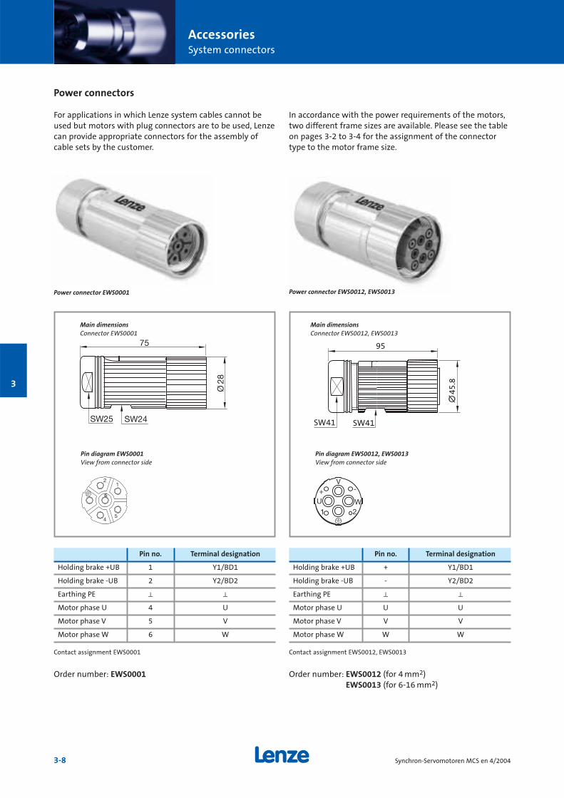
AccessoriesSystem connectors
3-8 Synchron-Servomotoren MCS en 4/2004
3
For applications in which Lenze system cables cannot beused but motors with plug connectors are to be used, Lenzecan provide appropriate connectors for the assembly ofcable sets by the customer.
In accordance with the power requirements of the motors,two different frame sizes are available. Please see the tableon pages 3-2 to 3-4 for the assignment of the connectortype to the motor frame size.
Power connectors
SW41
95
45.
8
SW41
Main dimensionsConnector EWS0012, EWS0013
Pin diagram EWS0001View from connector side
Pin diagram EWS0012, EWS0013View from connector side
Pin no. Terminal designation
Holding brake +UB 1 Y1/BD1
Holding brake -UB 2 Y2/BD2
Earthing PE k k
Motor phase U 4 U
Motor phase V 5 V
Motor phase W 6 W
Pin no. Terminal designation
Holding brake +UB + Y1/BD1
Holding brake -UB - Y2/BD2
Earthing PE k k
Motor phase U U U
Motor phase V V V
Motor phase W W W
Power connector EWS0001
Main dimensionsConnector EWS0001
6
Power connector EWS0012, EWS0013
Contact assignment EWS0001
Order number: EWS0001
Contact assignment EWS0012, EWS0013
Order number: EWS0012 (for 4 mm2)EWS0013 (for 6-16 mm2)
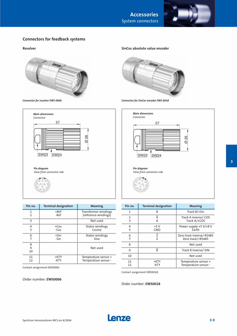
AccessoriesSystem connectors
3-9Synchron-Servomotoren MCS en 4/2004
3
Connectors for feedback systems
Main dimensionsConnector
Main dimensionsConnector
Pin diagramView from connector side
Pin diagramView from connector side
Pin no. Terminal designation Meaning
1 +Ref Transformer windings2 -Ref (reference windings)
3 Not used
4 +Cos Stator windings5 -Cos Cosine
6 +Sin Stator windings 7 -Sin Sine
89 Not used
10
11 +KTY Temperature sensor +12 -KTY Temperature sensor -
Pin no. Terminal designation Meaning
1 B Track B/+Sin
2 A Track A inverse/-COS3 A Track A/+COS
4 +5 V Power supply +5 V/+8 V5 GND Earth
6 Z Zero track inverse/-RS4857 Z Zero track/+RS485
8 Not used
9 B Track B inverse/-SIN
10 Not used
11 +KTY Temperature sensor +12 -KTY Temperature sensor -
Connector for resolver EWS 0006
Resolver SinCos absolute value encoder
Contact assignment EWS0006
Order number: EWS0006
Contact assignment EWS0018
Order number: EWS0018
Connector for SinCos encoder EWS 0018
4-1Synchron-Servomotoren MCS en 4/2004
Services MCS synchronous servo motors
Services4-2
Relateddocumentation
4-3
Product codes4-4
Fax order form4-6
Lenze worldwide4-8
4
ServicesServices
4-2 Synchron-Servomotoren MCS en 4/2004
4
For us, service is more than just supporting the use of ourdrives. The Lenze system approach begins with your enquiry. Next you get technical information and advicefrom a network of sales outlets staffed by knowledgeableengineers. If you want, we follow up with training, commissioning, maintenance and repair. Our service isalways at your disposal.
With passionThe Lenze team does not just offer the necessary manpower and technical know-how – we are passionateand meticulous about what we do. We will only be happyonce you are entirely satisfied with our work. Our team ofprofessionals provides assistance over the telephone or onsite, ensures the express delivery of spare parts and carriesout repairs with incredible urgency. We’re fast and reliable.
Someone to talk to Expert advice is available for all your technical queries viaour helpline. In cases of urgent need, call 008000 24 hours(008000 24 46877), Lenze’s worldwide expert helpline – 24 hours a day, 365 days a year. For more direct assistance,you can of course contact your local Lenze service supportcentre. We can tell you where it is – or you can find out foryourself by visiting us on the Internet at www.Lenze.com.
Around the worldOur products are available for speedy delivery worldwide.Lenze companies, Lenze factories and sales agencies arebased in major industrial countries around the world.Contact them through our website www.Lenze.com, whichalso gives you 24-hour access to technical instructions andproduct manuals. Local support, on site if you need it, isavailable.
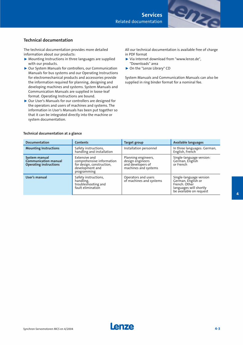
ServicesRelated documentation
4-3Synchron-Servomotoren MCS en 4/2004
4
Technical documentation
The technical documentation provides more detailed information about our products:˘ Mounting Instructions in three languages are supplied
with our products.˘ Our System Manuals for controllers, our Communication
Manuals for bus systems and our Operating Instructionsfor electromechanical products and accessories providethe information required for planning, designing anddeveloping machines and systems. System Manuals andCommunication Manuals are supplied in loose-leaf format. Operating Instructions are bound.
˘ Our User's Manuals for our controllers are designed forthe operators and users of machines and systems. Theinformation in User's Manuals has been put together sothat it can be integrated directly into the machine orsystem documentation.
All our technical documentation is available free of chargein PDF format˘ Via Internet download from "www.lenze.de",
"Downloads" area˘ On the "Lenze Library" CD
System Manuals and Communication Manuals can also besupplied in ring binder format for a nominal fee.
Documentation Contents Target group Available languages
Mounting Instructions Safety instructions, Installation personnel In three languages: German,handling and installation English, French
System manual Extensive and Planning engineers, Single-language version:Communication manual comprehensive information design engineers German, EnglishOperating instructions for design, construction, and developers of or French
development and machines and systemsprogramming
User’s manual Safety instructions, Operators and users Single-language versionhandling, of machines and systems German, English ortroubleshooting and French. Otherfault elimination languages will shortly
be available on request
Technical documentation at a glance
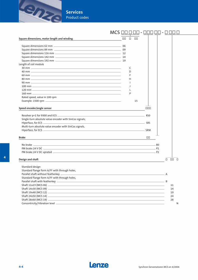
ServicesProduct codes
4-4 Synchron-Servomotoren MCS en 4/2004
4
Square dimensions, motor length and winding òò ò òò
Square dimensions 62 mm 06Square dimensions 89 mm 09Square dimensions 116 mm 12Square dimensions 142 mm 14Square dimensions 192 mm 19
Length of coil module30 mm C40 mm D60 mm F80 mm H90 mm I100 mm J120 mm L160 mm PRated speed, value in 100 rpmExample: 1500 rpm 15
Speed encoder/angle sensor òòò
Resolver p=1 for 9300 and ECS RS0Single-turn absolute value encoder with SinCos signals, Hiperface, for ECS SRSMulti-turn absolute value encoder with SinCos signals, Hiperface, for ECS SRM
Brake òò
No brake B0PM brake 24 V DC P1PM brake 24 V DC uprated P2
Design and shaft ò òò ò
Standard designStandard flange form A/FF with through holes, Parallel shaft without featherkey AStandard flange form A/FF with through holes, Parallel shaft with featherkey BShaft 11x23 (MCS 06) 11Shaft 14x30 (MCS 09) 14Shaft 19x40 (MCS 12) 19Shaft 24x50 (MCS 14) 24Shaft 28x60 (MCS 19) 28Concentricity/Vibration level N
MCS òò ò òò - òòò òò - ò òò ò
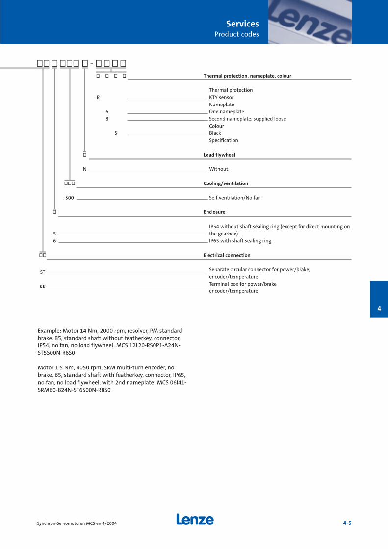
ServicesProduct codes
4-5Synchron-Servomotoren MCS en 4/2004
4
òò ò òòò ò - ò ò ò ò
Example: Motor 14 Nm, 2000 rpm, resolver, PM standardbrake, B5, standard shaft without featherkey, connector,IP54, no fan, no load flywheel: MCS 12L20-RS0P1-A24N-ST5S00N-R6S0
Motor 1.5 Nm, 4050 rpm, SRM multi-turn encoder, nobrake, B5, standard shaft with featherkey, connector, IP65,no fan, no load flywheel, with 2nd nameplate: MCS 06I41-SRMB0-B24N-ST6S00N-R8S0
ò ò ò ò Thermal protection, nameplate, colour
Thermal protectionR KTY sensor
Nameplate6 One nameplate8 Second nameplate, supplied loose
ColourS Black
Specification
ò Load flywheel
N Without
òòò Cooling/ventilation
S00 Self ventilation/No fan
ò Enclosure
IP54 without shaft sealing ring (except for direct mounting on 5 the gearbox)6 IP65 with shaft sealing ring
òò Electrical connection
ST Separate circular connector for power/brake,encoder/temperature
KK Terminal box for power/brakeencoder/temperature
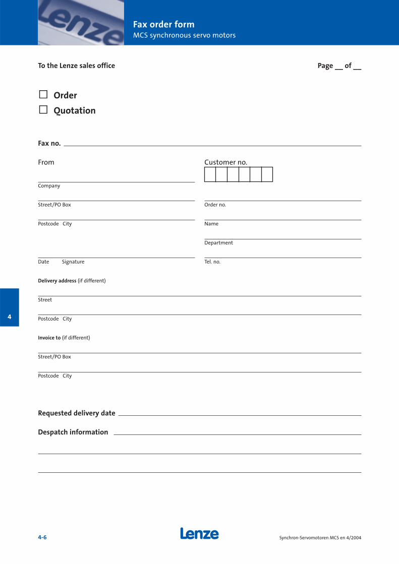
Fax order formMCS synchronous servo motors
4-6 Synchron-Servomotoren MCS en 4/2004
4
Fax no.
From Customer no.
Company
Street/PO Box Order no.
Postcode City Name
Department
Date Signature Tel. no.
Delivery address (if different)
Street
Postcode City
Invoice to (if different)
Street/PO Box
Postcode City
Requested delivery date
Despatch information
To the Lenze sales office Page __ of __
ò Order
ò Quotation
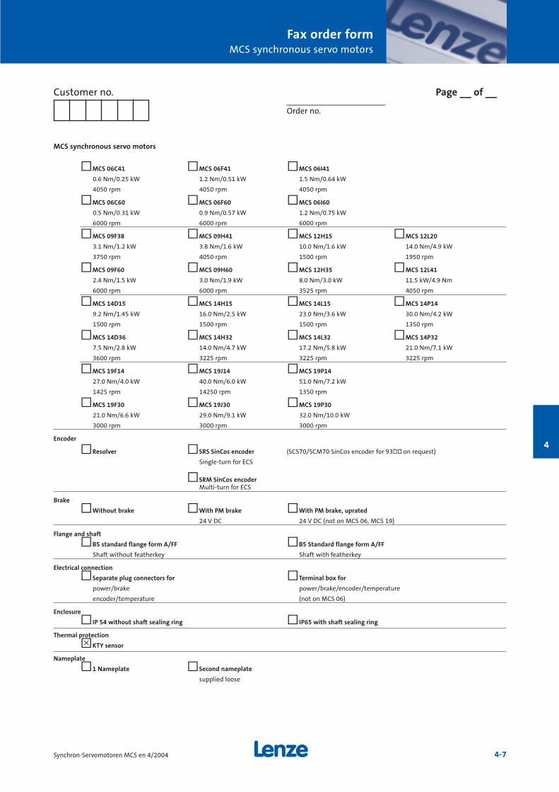
Fax order formMCS synchronous servo motors
4-7Synchron-Servomotoren MCS en 4/2004
4
MCS synchronous servo motors
òMCS 06C41 òMCS 06F41 òMCS 06I41
0.6 Nm/0.25 kW 1.2 Nm/0.51 kW 1.5 Nm/0.64 kW
4050 rpm 4050 rpm 4050 rpm
òMCS 06C60 òMCS 06F60 òMCS 06I60
0.5 Nm/0.31 kW 0.9 Nm/0.57 kW 1.2 Nm/0.75 kW
6000 rpm 6000 rpm 6000 rpm
òMCS 09F38 òMCS 09H41 òMCS 12H15 òMCS 12L20
3.1 Nm/1.2 kW 3.8 Nm/1.6 kW 10.0 Nm/1.6 kW 14.0 Nm/4.9 kW
3750 rpm 4050 rpm 1500 rpm 1950 rpm
òMCS 09F60 òMCS 09H60 òMCS 12H35 òMCS 12L41
2.4 Nm/1.5 kW 3.0 Nm/1.9 kW 8.0 Nm/3.0 kW 11.5 kW/4.9 Nm
6000 rpm 6000 rpm 3525 rpm 4050 rpm
òMCS 14D15 òMCS 14H15 òMCS 14L15 òMCS 14P14
9.2 Nm/1.45 kW 16.0 Nm/2.5 kW 23.0 Nm/3.6 kW 30.0 Nm/4.2 kW
1500 rpm 1500 rpm 1500 rpm 1350 rpm
òMCS 14D36 òMCS 14H32 òMCS 14L32 òMCS 14P32
7.5 Nm/2.8 kW 14.0 Nm/4.7 kW 17.2 Nm/5.8 kW 21.0 Nm/7.1 kW
3600 rpm 3225 rpm 3225 rpm 3225 rpm
òMCS 19F14 òMCS 19J14 òMCS 19P14
27.0 Nm/4.0 kW 40.0 Nm/6.0 kW 51.0 Nm/7.2 kW
1425 rpm 14250 rpm 1350 rpm
òMCS 19F30 òMCS 19J30 òMCS 19P30
21.0 Nm/6.6 kW 29.0 Nm/9.1 kW 32.0 Nm/10.0 kW
3000 rpm 3000 rpm 3000 rpm
Encoder
òResolver òSRS SinCos encoder (SCS70/SCM70 SinCos encoder for 93òò on request)
Single-turn for ECS
òSRM SinCos encoderMulti-turn for ECS
Brake
òWithout brake òWith PM brake òWith PM brake, uprated
24 V DC 24 V DC (not on MCS 06, MCS 19)
Flange and shaft
òB5 standard flange form A/FF òB5 Standard flange form A/FF
Shaft without featherkey Shaft with featherkey
Electrical connection
òSeparate plug connectors for òTerminal box for
power/brake power/brake/encoder/temperature
encoder/temperature (not on MCS 06)
Enclosure
òIP 54 without shaft sealing ring òIP65 with shaft sealing ring
Thermal protection
òKTY sensor
Nameplate
ò1 Nameplate òSecond nameplate
supplied loose
Customer no. Page __ of __
Order no.
ô
Lenze worldwide
4-8 Synchron-Servomotoren MCS en 4/2004
4
Lenze AGPostfach 101352D-31763 HamelnTelefon +49 (0)51 54/82-0Telefax +49 (0)51 54/82-28 00E-Mail: [email protected]: www.Lenze.com
Lenze Drive Systems GmbH
Postfach 10 13 52, D-31763 HamelnTelefon +49 (0)51 54 / 82-0Telefax +49 (0)51 54 / 82-28 00
Lenze GmbH & Co KG Anlagenbau
Buchenweg 1D-31855 AerzenTelefon +49 (0)51 54 / 82-0Telefax +49 (0)51 54 / 82-21 00
Lenze Bremsen GmbH
Wülmser Weg 5D-31855 AerzenTelefon +49 (0)51 54 / 82-14 53Telefax +49 (0)51 54 / 82-11 04
Lenze GmbH & Co KG Kleinantriebe
Hans-Lenze-Straße 1D-32699 ExtertalTelefon +49 (0)51 54 / 82-0Telefax +49 (0)51 54 / 82-14 85
Lenze Service GmbH
Breslauer Straße 3D-32699 Extertal
Mechanical DrivesTelefon +49 (0)51 54 / 82-16 26Telefax +49 (0)51 54 / 82-13 96
Electronic DrivesTelefon +49 (0)51 54 / 82-11 11Telefax +49 (0)51 54 / 82-11 12
Service Helpline +49 (0)180 5 20 24 26
Lenze Verbindungstechnik GmbH & Co KGI
Ipf-Landesstraße 1A-4481 ASTENPhone +43 (0)72 24 / 21 1-0Telefax +43 (0)72 24 / 21 19 98
Lenze Deto Drive Systems GmbH & Co KG
Gewerbepark Süd 11A-6330 KufsteinTelefon +43 (0)53 72 / 6 53 15-200Telefax +43 (0)53 72 / 6 53 15-299
LS Automation GmbH & Co KG
Jakob-Stadler-Platz 11D-78467 KonstanzTelefon +49 (0)75 31 /9 42 19-0Telefax +49 (0)75 31 /9 42 19 20
encoway GmbH & Co KG
Universitätsallee 21-23D-28359 BremenTelefon +49 (0)4 21 /2 46 77-0Telefax +49 (0)4 21 /2 46 77-10
DEUTSCHLAND/GERMANY
Lenze Vertrieb GmbH
Ludwig-Erhard-Straße 52-56D-72760 ReutlingenTelefon +49 (0)71 21 / 9 39 39-0Telefax +49 (0)71 21 / 9 39 39-29
Region NordDornenpark 131840 Hessisch OldendorfTelefon (0 51 52) 90 36-0Telefax (0 51 52) 90 36-33/44/55
Region WestPostfach 10 12 2047497 Neukirchen-VluynKelvinstraße 747506 Neukirchen-VluynTelefon (0 28 45) 95 93-0Telefax (0 28 45) 95 93 93
Region Mitte/OstPostfach 146335724 HerbornAustraße 8135745 HerbornTelefon (0 27 72) 95 94-0Telefax (0 27 72) 5 30 79
Region SüdwestPostfach 14 3371304 WaiblingenSchänzle 871332 WaiblingenTelefon (0 71 51) 9 59 81 - 0Telefax (0 71 51) 9 59 81 50
Region SüdFraunhoferstraße 1682152 MartinsriedTelefon (0 89) 89 56 14-0Telefax (0 89) 89 56 14 14
WELTWEIT/WORLDWIDE
ALGERIA
see FRANCE
ARGENTINA *
E.R.H.S.A.Girardot 1368, 1427 BUENOS AIRESPhone +54 (0)11 / 45 54 32 32Telefax +54 (0)11 / 45 52 36 11
AUSTRALIA *
FCR Motion Technology Pty. Ltd.Unit 6, Automation Place38-40 Little Boundary Rd.LAVERTON NORTH, Vic. 3026 Phone +61 (3) 9362 6800 Telefax +61 (3) 9314 3744
AUSTRIA *
Lenze Antriebstechnik GmbHIpf-Landesstraße 14481 ASTENPhone +43 (0)7224 / 21 0-0Telefax +43 (0)7224 / 21 09 99
Office Dornbirn:Lustenauer Straße 646850 DORNBIRN Phone +43 (0)5572 / 26 789-0Telefax +43 (0)5572 / 26 789-66
Office Wr. Neudorf:Triester Straße 14/1092351 WR. NEUDORFPhone +43 (0)2236 / 2 53 33-0Telefax +43 (0)2236 / 2 53 33-66
Office Graz:Seering 88141 UNTERPREMSTÄTTENPhone +43 (0)3135 / 56 900-0Telefax +43 (0)3135 / 56 900 999
Lenze Verbindungstechnik GmbH & Co KGIpf-Landesstraße 14481 ASTENPhone +43 (0)7224 / 21 1-0Telefax +43 (0)7224 / 21 19 98
Lenze Anlagentechnik GmbH & Co KGMühlenstraße 34470 ENNSPhone +43 (0)7223 / 886-0Telefax +43 (0)7223 / 886-997
BELGIUM *
Lenze b.v.b.aNoorderlaan 133bus 152030 ANTWERPENPhone +32 (0)3 / 54 26 20 0Telefax +32 (0)3 / 54 13 75 4
BOSNIA-HERZEGOVINA
see AUSTRIA
BRAZIL *
AC Control LtdaRua Gustavo da Silveira 1199 Vila Sta. CatarinaSÃO PAULO – S.P.04376-000Phone (+55) 11 55 64 65 79 ramal: 214Telefax (+55) 11 56 79 75 10
BULGARIA
see MACEDONIA
CANADA *
see USA
CHILE
Sargent S.A.Tecnica Thomas C. SargentS.A.C.é.l.Casilla 166-DSANTIAGO DE CHILEPhone +56 (0)2 / 51 03 000Telefax +56 (0)2 / 69 83 989
Aupi Ltda.Automation y Proceso IndustrialCamino a Melipilla No. 262Casilla 80SANTIAGO DE CHILEPhone +56 (0)2 / 811 45 20Telefax +56 (0)2 / 811 11 02 / 811 18 04
CHINA *
Lenze Mechatronic Drives (Shanghai) Co. Ltd., Section B, 50# building,No.199 North Ri Ying Road,Waigaoqiao Free Trade ZoneSHANGHAI, 200131Phone +86-21-5046 0848Telefax +86-21-5046 0850
Beijing OfficeRm. 401, Huaxin MansionNo. 33 An Ding RoadChaoyang DistrictBEIJING 100029Phone +86-10-6441 1470Telefax +86-10-6441 1467
CROATIA
Lenze Antriebstechnik GmbHPredstavnista ZagrebUlica Grada Gospica 3HR-1000 ZAGREBPhone +385-1-2 49 80 56Telefax +385-1-2 49 80 57
CZECH REPUBLIC
Lenze, s.r.o.Central Trade Park D1396 01 HUMPOLECPhone +420 565 507-111Telefax +420 565 507-399
Büro âerven˘ Kostelec:17. listopadu 510 549 41 âERVEN¯ KOSTELECPhone +420 491 467-111Telefax +420 491 467-166
DENMARK *
Lenze A/SVallensbækvej 18A2605 BRØNDBYPhone +45 / 46 96 66 66Telefax +45 / 46 96 66 6024 stunde service +45 / 40 93 04 11
Buero Jylland:Lenze A/SEnebærvej 118653 THEMPhone +45 / 46 96 66 66Telefax +45 / 46 96 66 80
EGYPT
WADI Co. for technologies and developmentP.O.Box 209, new center Ramses11794 CAIRO, Egypt11 Syria St., MohandessinGIZA, EgyptPhone +20 (2) 347 6842Telefax +20 (2) 347 6843
ESTONIA
see FINLAND
FINLAND *
Lenze DrivesRykmentintie 2 b20810 TURKUPhone +358 2 2748 180Telefax +358 2 2748 189
FRANCE *
Lenze S.A.SiegeZ.A. de ChanteloupRue Albert Einstein93603 AULNAY-SOUS-BOIS
Services CommerciauxTel. 0 825 086 036Fax 0 825 086 346
Centre de formationE-Mail:[email protected]
Question générales / DocumentationE-Mail:[email protected]
Service Après-vente / asssistance en ligneHelpline 24/24 : 0 825 826 117 E-Mail:[email protected]
Agences en FranceRégion France Nord :Z.A. de ChanteloupRue Albert Einstein93603 AULNAY-SOUS-BOIS
Lille59420 MOUVAUX
Strasbourg67960 ENTZHEIM
Rouen76500 ELBEUF
Région France Sud :Rond point du sans souci69578 LIMONEST Cedex
Toulouse31400 TOULOUSE
Agen47270 SAINT-PIERRE DE CLAIRAC
GREECE
George P. Alexandris S.A.12K. Mavromichali Str.185 45 PIRAEUSPhone +30 (0)210 / 41 11 84 15Telefax +30 (0)210 / 4 11 81 71
4 12 70 58183 Monastiriou Str. 546 27 THESSALONIKIPhone +30 (0)310 / 5 56 65 04Telefax +30 (0)310 / 51 18 15
HUNGARY *
Lenze AntriebstechnikHandelsgesellschaft mbH2040 BUDAÖRSGyár utca 2., P.O.Box 322.Phone +36 (0)23 / 501-320Telefax +36 (0)23 / 501-339
ICELAND
see DENMARK
Lenze worldwide
4-9Synchron-Servomotoren MCS en 4/2004
4
INDIA
Electronic Service:National Power Systems10, Saibaba Shopping CentreKeshav Rao Kadam MargOff Lamington RoadMUMBAI 400 008Phone +91-22-2300 5667, 2301 3712 Telefax +91-22-2300 5668
Mechanical Service:Emco Lenze Pvt. Ltd.1st Floor, Sita MauliMadanlal Dhingra RoadPanch Pakhadi, Thane (West)MAHARASHATRA 400 602Phone +91-22-25405488
+91-22-25452244Telefax +91-22-25452233
V3 Controls Pvt. Ltd.1, “Devyani”, Next to SBI, Baner ITI Road,Sanewadi, Aundh,PUNE 411 007, MSPhone +91-20-25 88 68 62Telefax +91-20-25 88 03 50
INDONESIA
P.T. Futurindo GlobalsatyaJl.: Prof. Dr. Latumenten No. 18Kompleks PerkantoranKota Grogol Permai Blok A 35JAKARTA 11460Buero 1:Phone +62 (0)21 / 766 42 34
765 86 23Telefax +62 (0)21 / 766 44 20Buero 2:Phone +62 (0)21 / 567 96 31
567 96 32Telefax +62 (0)21 / 566 87 50
IRAN
Tavan Ressan Co. Ltd.P.O.Box. 19395-5177No. 44, Habibi St.,South Dastour St.,Sadr EXP’Way,TEHRAN 19396Phone +98 21 / 260 26 55
260 67 66260 92 99
Telefax +98 21 / 200 28 83
ISRAEL *
Greenshpon Engineering Works LTDBar-Lev Industrial ParkMISGAV 20179Phone +972 4 99 13 18 1Telefax +972 4 99 13 47 7
ITALY *
Gerit Trasmissioni S.p.A.Viale Monza 33820128 MILANOPhone +39 02 / 270 98.1Telefax +39 02 / 270 98 290
JAPAN *
Miki Pulley Co., Ltd.1-39-7 Komatsubara, Zama-cityKANAGAWA 228-8577Phone +81 (0)462 / 58 16 61Telefax +81 (0)462 / 58 17 04
LATVIA
see LITHUANIA
LITHUANIA
Lenze UABBreslaujos g.344403 KAUNASPhone +370 37 407174Fax./Tel.+370 37 407175
LUXEMBOURG *
see BELGIUM
MACEDONIA
Lenze Antriebstechnik GmbHPretstavnistvo Skopjeul. Nikola Rusinski 3/A/2, 1000 SKOPJEPhone +389 2 30 90 090Telefax +389 2 30 90 091
MALAYSIA
D.S.C. Engineering SDN BHD3A & 3B, Jalan SS21/56BDamansara Utama47400, PETALING JAYA, SELANGOR Phone +60 (0)3 / 77 25 62 43
77 25 62 4677 28 65 30
Telefax +60 (0)3 / 77 29 50 31
MAURITIUS
Automation & Controls Engineering Ltd3, Royal Road, Le Hochet, Terre RougeMAURITIUSPhone +230 248 8211Telefax +230 248 8968
MEXICO
Automatización y Control de Energía S.A. de C.V.Av. 2 No. 89 Esq Calle 13Col. San Pedro de los PinosC.P. 03800 MEXICO D.F.Phone +52 (55)5277/5998Telefax +52 (55)5277/5937
MOROCCO
GUORFET G.T.D.R Automatisation IndustrielleBd Chefchaouni Route 110 km, 11.500No. 353-Aîn-SabaâCASABLANCAPhone +212/22-35 70 78Telefax +212/22-35 71 04
NETHERLANDS *
Lenze B.V., Postbus 31 015203 DC`S-HERTOGENBOSCHPloegweg 155232 BR`S-HERTOGENBOSCHPhone +31 (0)73 / 64 56 50 0Telefax +31 (0)73 / 64 56 51 0
NEW ZEALAND *
Tranz Corporation343 Church StreetP.O. Box 12-320, PenroseAUCKLANDPhone +64 (0)9 / 63 45 51 1Telefax +64 (0)9 / 63 45 51 8
NORWAY *
Dtc- Lenze asStallbakken 5, 2005 RAELINGENPhone +47 / 64 80 25 10Telefax +47 / 64 80 25 11
PHILIPPINES
Jupp & Company Inc.Unit 224 Cityland Pioneer Bldg.,Pioneer Sreet, MANDALUYONG CITYPhone +63 2 / 687 7423
683 0042683 0047
Telefax +63 2 / 687 7421
POLAND
Lenze-Rotiw Sp. z o.o.ul. Ro˝dzieƒskiego 188b40-203 KATOWICEPhone +48 (0)32 / 2 03 97 73Telefax +48 (0)32 / 7 81 01 80
Lenze Systemy Automatyki Sp. z o.o.Ul. Rydygiera 4787-100 TORU¡Phone +48 (0)56 / 6 58 28 00
6 45 34 606 45 35 70
Telefax +48 (0)56 / 6 45 33 56
PORTUGAL *
Costa Leal el VictorElectronica-Pneumatica, Lda.Rua Prof. Augusto Lessa, 269,Apart. 520534202-801 PORTOPhone +351-22 / 5 50 85 20Telefax +351-22 / 5 02 40 05
ROMANIA
see AUSTRIA
RUSSIA
Inteldrive1 Buhvostova Street 12/11Korpus 18 Office 322MOSCOW 107258Phone +7 (0)095 / 963 96 86Telefax +7 (0)095 / 962 67 94
SERBIA-MONTENEGRO
see MACEDONIA
SINGAPORE *
see MALAYSIA
SLOVAC REPUBLIC
ECS Sluzby spol. s.r.o.Staromlynska 2982106 BRATISLAVAPhone +421 2 45 25 96 06
+421 2 45 64 31 47+421 2 45 64 31 48
Telefax +421 2 45 25 96 06
SLOVENIA
Lenze pogonska tehnika GmbHZbiljska Cesta 41215 MEDVODEPhone +386 (0)1 361 61 41Telefax +386 (0)1 361 22 88
SOUTH AFRICA *
S.A. Power Services (Pty.) Ltd.P.O. Box 11 37RANDBURG 2125Phone +27 (0)11 / 78 71 80 1Telefax +27 (0)11 / 78 75 04 0
SOUTH KOREA *
Hankuk Mechatro Ltd.Room# 1409 Samhwan officetel 830-295Beomil-dong, Dong-GuPUSANPhone +82 (0)51-635-6663Telefax +82 (0)51-635-6632
SPAIN *
Lenze Transmisiones, S.A.Mila i Fontanals, 135-13908205 SABADELL (Barcelona)Phone +34 93 / 72 07 68 0Telefax +34 93 / 71 22 54 1
SWEDEN *
Lenze Transmissioner ABP.O.Box 10 74, Attorpsgatan, Tornby Ind.58110 LINKÖPINGPhone +46 (0)13 / 35 58 00Telefax +46 (0)13 / 10 36 23
SWITZERLAND *
Lenze Bachofen AGAckerstrasse 458610 USTERPhone +41 (0) 43 399 14 14Telefax +41 (0) 43 399 14 24
Vente Suisse Romande:Route de Prilly 251023 CRISSIERPhone +41 (0)21 / 63 72 19 0Telefax +41 (0)21 / 63 72 19 9
SYRIA
Zahabi Co.8/5 Shouhadaa StreetP.O.Box 8262ALEPPO-SYRIAPhone +963 21 21 22 23 5Telefax +963 21 21 22 23 7
TAIWAN *
ACE Pillar Co. Ltd.No.12, Lane 61, Sec. 1, Kuanfu RoadSan-Chung CityTAIPEI HSIENPhone +886 (0)2 / 299 58 40 0Telefax +886 (0)2 / 299 53 46 6
THAILAND
PackSys Global (Thailand) Ltd.429 Moo 7, Theparak Road, Tambol TheparakAmphur MuangSAMUTPRAKARN 10270Phone +66 2 383 5633Telefax +66 2 383 5637
TUNESIA
AMF Industrielle SarlRoute de Gremda - Km 0,2Immeuble El Madina,Centre Bloc B - 5 ème - appt 523002 SFAXPhone +216 74 403 514Telefax +216 74 402 516
TURKEY
LSE Elektrik Elektronik MakinaOtomasyon Mühendislik San. Ve Tic. Ltd. Ωti.Atatürk mah. Cumhuriyet cad.Yurt sok. No:7ÜMRANIYE/∑STANBULPhone +90 (0)216 / 316 5138 pbxTelefax +90 (0)216 / 443 4277
Bursa Address:Demirtaspasa Mh.Ata Sk. Petek Bozkaya Is MerkeziD Blok No :5 / A OSMANGAZI / BURSAPhone +90 (0)224-2733232 pbx
+90 (0)224-2734151+90 (0)224-2733238
Telefax +90 (0)224-2734150
UKRAINE
SV AlteraPobedy Av. 44, KIYVPhone +380-44-2416777Telefax +380-44-2419084
UNITED KINGDOM/EIRE *
Lenze Ltd.Caxton RoadBEDFORD MK 41 OHTPhone +44 (0)1234 / 32 13 21Telefax +44 (0)1234 / 26 18 15
USA *
AC Technology Corp.660 Douglas StreetUXBRIDGE, MA 01569Phone +1 508 / 278-9100Telefax +1 508 / 278-7873
AC Technology Corp.1730 East Logan AvenueEMPORIA, KS 66 801 Phone +1 620 / 343-8401
+1 888 / 269-2381Telefax +1 620 / 342-2595
+1 800 / 469-0931
AC Technology Corp.1 W. Illinois Street, Suite 240ST. CHARLES, IL 60174Phone +1 630 / 377-7534Telefax +1 630 / 377-9623
œ* Countries connected to the free expert helpline 008000 24 hours (008000 24 46877)
Service you can trust
For us, service is more than just supporting
the use of our drives. The Lenze system
approach begins with your enquiry. Next
you get technical information and advice
from a network of sales outlets staffed by
knowledgeable engineers. If you want,
we follow up with training, commissio-
ning, maintenance and repair. Our service
is always at your disposal.
With passion
The Lenze team does not just offer the
necessary manpower and technical know-
how – we are passionate and meticulous
about what we do. We will only be happy
once you are entirely satisfied with our
work. Our team of professionals provides
assistance over the telephone or on site,
ensures the express delivery of spare parts
and carries out repairs with incredible
urgency. We’re fast and reliable.
Someone to talk to
Expert advice is available for all your
technical queries via our helpline. In cases
of urgent need, call 008000 24 hours
(008000 24 46877), Lenze’s worldwide
expert helpline – 24 hours a day, 365 days
a year. For more direct assistance, you can
of course contact your local Lenze service
support centre. We can tell you where it
is – or you can find out for yourself by
visiting us on the Internet at
www.Lenze.com.
Around the world
Our products are available for speedy
delivery worldwide. Lenze companies, Lenze
factories and sales agencies are based in
major industrial countries around the
world. Contact them through our website
www.Lenze.com, which also gives you
24-hour access to technical instructions
and product manuals. Local support, on
site if you need it, is available.
www.Lenze.comLe
nze
Dri
ve S
yste
ms
Gm
bH
· Po
stfa
ch 1
013
52· D
-317
63 H
amel
n ·
Tech
nic
al a
lter
atio
ns
rese
rved
· Pr
inte
d in
Ger
man
y 4.
2004
en
· 5 4
3 2
1
486 741
WorldwideAlgeriaArgentinaAustraliaAustriaBelgiumBosnia-HerzegovinaBrazilBulgariaCanadaChile ChinaCroatiaCzech RepublicDenmarkEgyptEstoniaFinlandFrance
GermanyGreeceHungaryIcelandIndiaIndonesiaIranIsraelItalyJapanLatviaLithuaniaLuxembourgMacedoniaMalaysiaMauritiusMexicoMoroccoNetherlands
New ZealandNorwayPhilippinesPolandPortugalRomaniaRussiaSerbia-MontenegroSingaporeSlovak Republic
SloveniaSouth Africa
South KoreaSpainSwedenSwitzerlandSyriaTaiwanThailandTunesiaTurkey
UkraineUnited
Kingdom/EireUSA