mctf hardware development plans
DESCRIPTION
MCTF Hardware Development Plans. Focus on Support for Muon Collider Magnets at Fermilab. Michael Lamm. MCTF Magnet Effort. **Called out in MCTF charge**. Primary Focus on Support specific magnet projects for 6D Cooling Demonstration Experiment Helical Cooling Channels and Matching Sections - PowerPoint PPT PresentationTRANSCRIPT
08/08/07MCTF Hardware Plans 1Fermilab AACMCTF
MCTF Hardware Development Plans
Michael Lamm
Focus on Support for Muon Collider Magnets at Fermilab
08/08/07MCTF Hardware Plans 2Fermilab AACMCTF
MCTF Magnet Effort
• Primary Focus on – Support specific magnet projects for 6D Cooling
Demonstration Experiment• Helical Cooling Channels and Matching Sections
• Coordination with AP and Detector groups
– Very high field solenoid for final stages of cooling• HTS Conductor R&D
• Magnet Design
• Organization of a National Collaboration
• Other tasks– Next generation HCC (newly approved Muons Inc SBIR)
– Collider and IR magnets for Muon Collider
**Called out in MCTF charge**
08/08/07MCTF Hardware Plans 3Fermilab AACMCTF
Helical Cooling Channel
• Cooling Channels proposed by Muons Inc for MANX experiment. (See R. Johnson and K. Yonehara presentations)
• Time scale for experiment: ~2010 • Solenoid, with superimposed helical quad/dipole filled
with low Z material can reduce 6D emittance• No RF Cavity
– HCC field reduced along helix to compensate for dE/dx loss
– Design should be compatible with adding RF in future
08/08/07MCTF Hardware Plans 4Fermilab AACMCTF
Conceptual Design Decision
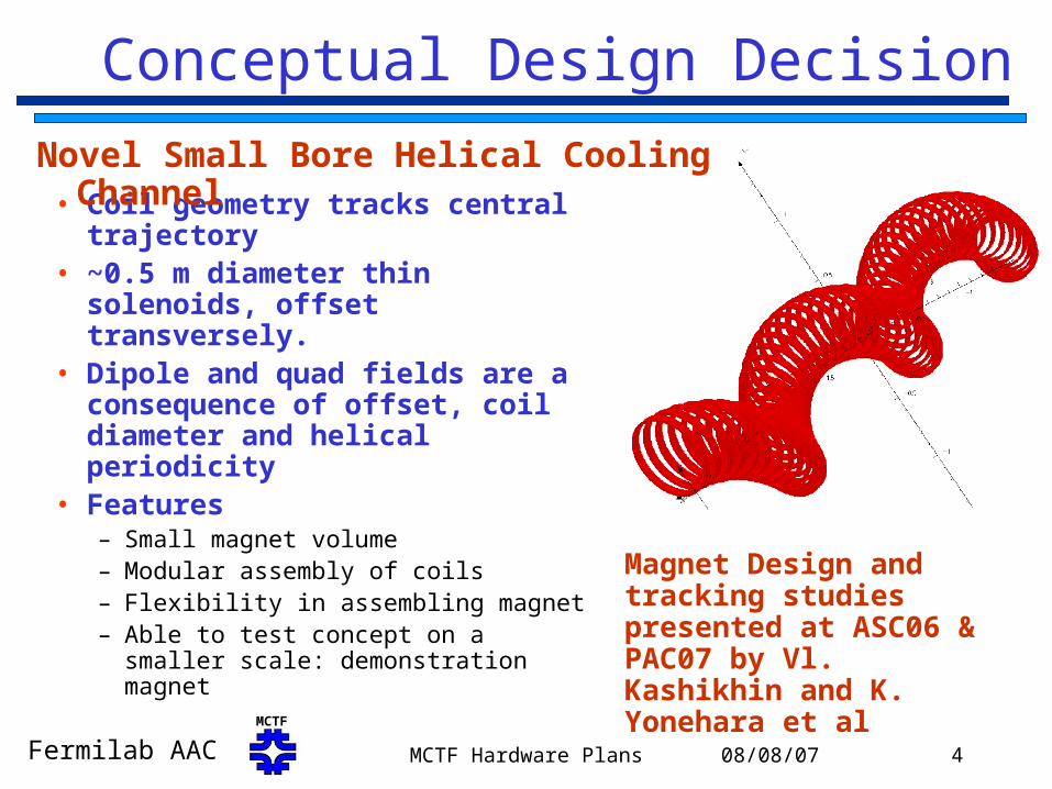
• Coil geometry tracks central trajectory
• ~0.5 m diameter thin solenoids, offset transversely.
• Dipole and quad fields are a consequence of offset, coil diameter and helical periodicity
• Features – Small magnet volume– Modular assembly of coils– Flexibility in assembling magnet– Able to test concept on a smaller
scale: demonstration magnet
Novel Small Bore Helical Cooling Channel
Magnet Design and tracking studies presented at ASC06 & PAC07 by Vl. Kashikhin and K. Yonehara et al

08/08/07MCTF Hardware Plans 5Fermilab AACMCTF
Design Parameters for Helical Solenoid
Latest parameters from: MOPAS012 PAC07 Vl. Kashikhin et al
Parameter Unit Value
Inner bore diameter m 0.5
Helical Solenoid length m 3.2
Helix twist pitch m 1.6
Radius of beam reference orbit m 0.255
Initial dipole field, BT 1.25
Dipole field gradient,B/z T/m -0.17
Initial quadrupole field, B/r T/m -0.88
Quadrupole field gradient,2B/r/z T/m2 0.07
Initial field, BzT -3.86
Longitudinal field gradient,Bz/z T/m 0.54
NbTi superconductor peak field T 5.7
Operational current kA 10
Operating stored energy MJ 4.4
Coil section length along Z axis mm 20
Superconducting cable length km 3.3
Manageable SC peak field, stored energy, operating current, SC cable length
08/08/07MCTF Hardware Plans 6Fermilab AACMCTF
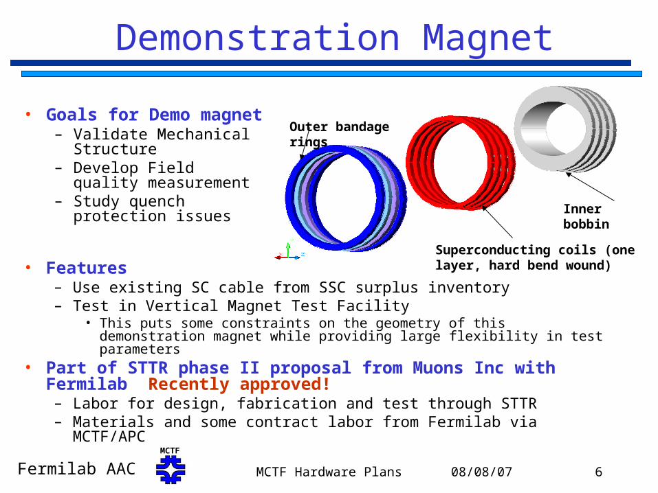
Outer bandage rings
Inner bobbin
Superconducting coils (one layer, hard bend wound)
Demonstration Magnet
• Features– Use existing SC cable from SSC surplus inventory– Test in Vertical Magnet Test Facility
• This puts some constraints on the geometry of this demonstration magnet while providing large flexibility in test parameters
• Part of STTR phase II proposal from Muons Inc with Fermilab Recently approved!– Labor for design, fabrication and test through STTR– Materials and some contract labor from Fermilab via MCTF/APC
• Goals for Demo magnet– Validate Mechanical
Structure– Develop Field quality
measurement – Study quench protection
issues
08/08/07MCTF Hardware Plans 7Fermilab AACMCTF
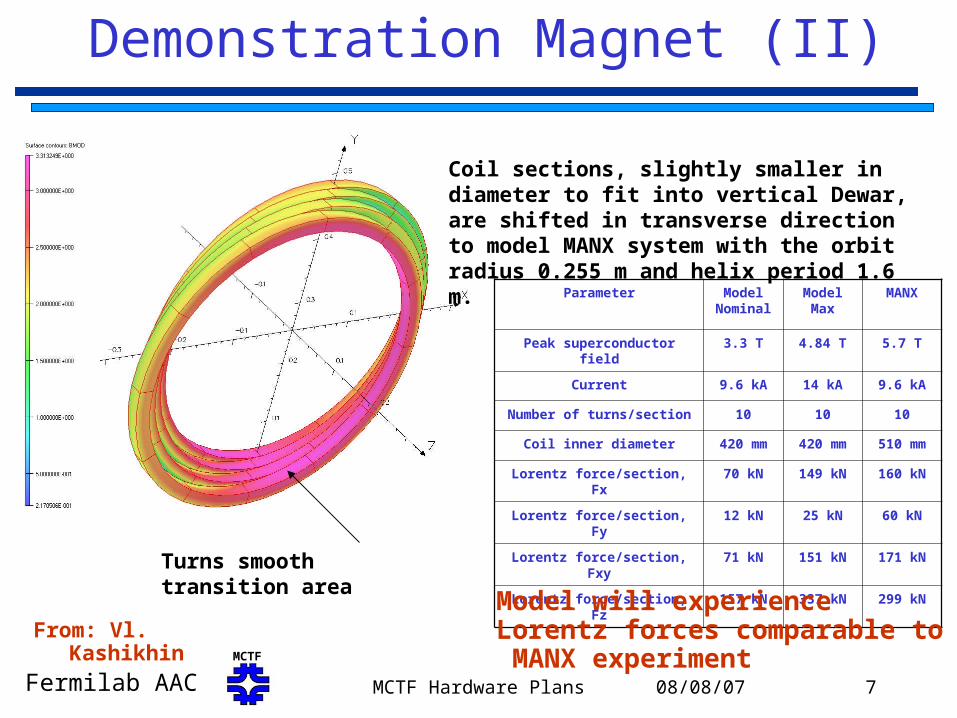
Demonstration Magnet (II)
Parameter Model Nominal
Model Max
MANX
Peak superconductor field 3.3 T 4.84 T 5.7 T
Current 9.6 kA 14 kA 9.6 kA
Number of turns/section 10 10 10
Coil inner diameter 420 mm 420 mm 510 mm
Lorentz force/section, Fx 70 kN 149 kN 160 kN
Lorentz force/section, Fy 12 kN 25 kN 60 kN
Lorentz force/section, Fxy 71 kN 151 kN 171 kN
Lorentz force/section, Fz 157 kN 337 kN 299 kNTurns smooth transition area
Coil sections, slightly smaller in diameter to fit into vertical Dewar, are shifted in transverse direction to model MANX system with the orbit radius 0.255 m and helix period 1.6 m.
Model will experience Lorentz forces comparable to MANX experimentFrom: Vl. Kashikhin
08/08/07MCTF Hardware Plans 8Fermilab AACMCTF
Demonstration Magnet Status
• Design work started prior to start of STTR phase II
•Mechanical/Magnetic Design underway
•COMSOL 3D FEM electromagnetic and stress analysis shows coil stress a very manageable <50 MPa at peak field.
• Need approximately 3-4 km of SSC inner cable for MANX experiment. We have acquired over 10 km from SSC cable surplus. Tests will be performed on extracted stands this fall to validate expected strand performance.
• Internal design review sometime in Fall 2007/Winter 2008
• Goal is to test magnet in Fall 2008

08/08/07MCTF Hardware Plans 9Fermilab AACMCTF
HCC Issues
• Demonstration magnet should validate magnetic and mechanical design by end CY08
• Decide if matching sections are required for MANX
• Complete specification for full scale MANX HCC including: field quality and “in situ” field monitoring; interface with particle tracking; cryostat details including helium requirements; powering scheme for dE/dx loss compensation; quench protection; other infrastructure needs
• Need approximately 2 years from final design to magnet fabrication and installation, i.e. need to complete studies in 2008 for a 2010 schedule
08/08/07MCTF Hardware Plans 10Fermilab AACMCTF
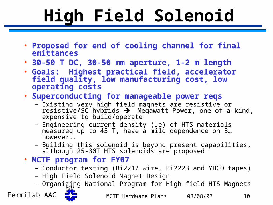
High Field Solenoid
• Proposed for end of cooling channel for final emittances• 30-50 T DC, 30-50 mm aperture, 1-2 m length• Goals: Highest practical field, accelerator field quality,
low manufacturing cost, low operating costs• Superconducting for manageable power reqs
– Existing very high field magnets are resistive or resistive/SC hybrids Megawatt Power, one-of-a-kind, expensive to build/operate
– Engineering current density (Je) of HTS materials measured up to 45 T, have a mild dependence on B… however..
– Building this solenoid is beyond present capabilities, although 25-30T HTS solenoids are proposed
• MCTF program for FY07– Conductor testing (Bi2212 wire, Bi2223 and YBCO tapes)– High Field Solenoid Magnet Design– Organizing National Program for High field HTS Magnets

08/08/07MCTF Hardware Plans 11Fermilab AACMCTF
Je(B,4.2 K) of HTS Conductorscirca 2005
Unpublished data, Schwartz, Trociewitz, Weijers & Schneider-Muntau
0
200
400
600
800
1000
1200
1400
0 5 10 15 20 25 30 35 40 45 50
B [T]
Je [
A/m
m2]
AMSC 2223 B||ab 2005
AMSC 2223, B || c
YBCO B||ab 2005
YBCO B||c 2005
OST Bi2212 RW
OST Bi2212 B||ab
OST Bi2212 B||c
4.2 K, 5mV/cm
Bi2212YBCO
Bi2223
Private Communication: J. Schwartz
NbTi Limit
Nb3Sn Limit

08/08/07MCTF Hardware Plans 12Fermilab AACMCTF
Conductor Testing at Fermilab
B
SAMPLE
I
B c
b a
IB
Probe for Angular Measurements
Courtesy of E. Barzi
08/08/07MCTF Hardware Plans 13Fermilab AACMCTF
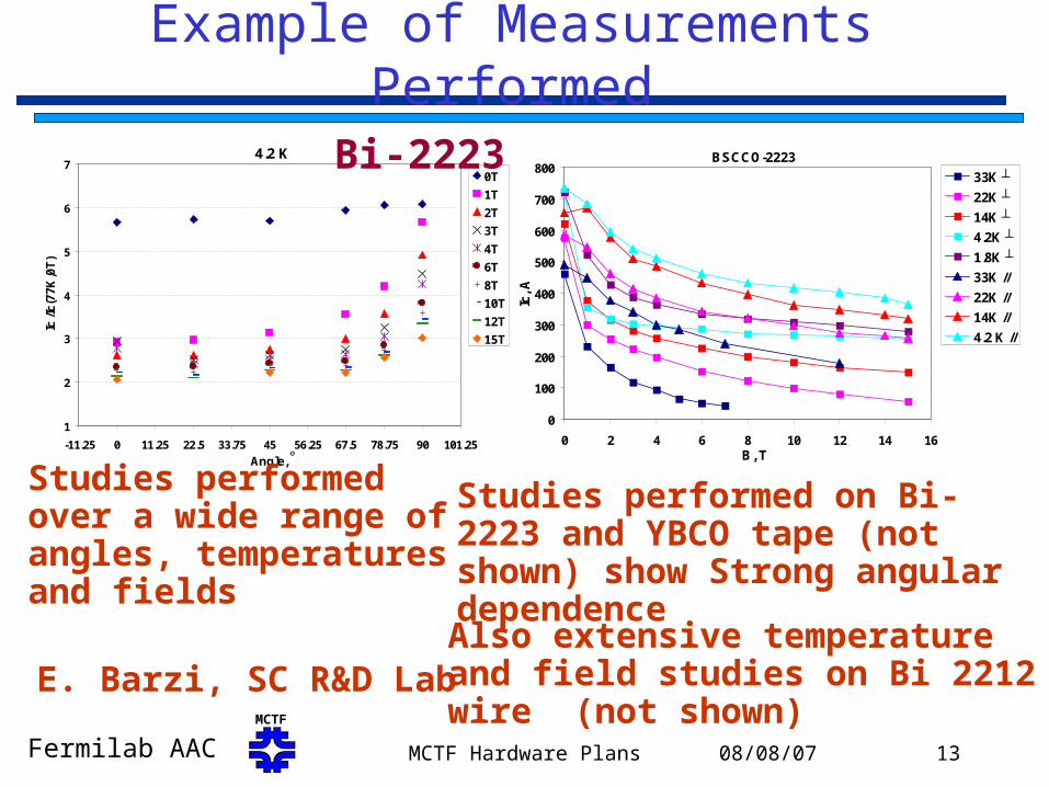
Example of Measurements Performed
4.2 K
1
2
3
4
5
6
7
-11.25 0 11.25 22.5 33.75 45 56.25 67.5 78.75 90 101.25
Angle, o
Ic /I
c(7
7K
,0T
)
0T
1T
2T
3T
4T
6T
8T
10T
12T
15T
Bi-2223 BSCCO-2223
0
100
200
300
400
500
600
700
800
0 2 4 6 8 10 12 14 16B, T
Ic, A
33K ┴
22K ┴
14K ┴
4.2K ┴
1.8K ┴
33K //
22K //
14K //
4.2 K //
Studies performed on Bi-2223 and YBCO tape (not shown) show Strong angular dependence
Studies performed over a wide range of angles, temperatures and fields
E. Barzi, SC R&D LabAlso extensive temperature and field studies on Bi 2212 wire (not shown)
08/08/07MCTF Hardware Plans 14Fermilab AACMCTF
High Field Solenoid Designs
• Two studies high field solenoid studies related to the MCTF have been performed in the last ~15 months– Steve Kahn and Bob Palmer
• Discussed in MCTF talk at Dec 2006 AAC meeting
• Updated at Low Emittance Workshop
– Vadim Kashikhin and Sasha Zlobin• Presented at Low Emittance Workshop
• Updated version to be presented at MT-20 August 2007
– Parameters• Hybrid magnet with NbTi, Nb3Sn and HTS superconductor
• Utilize Bi-2223 tapes (steel reinforced, long lengths and reasonable Jc)
• Bi-2212 wire is also possible

08/08/07MCTF Hardware Plans 15Fermilab AACMCTF
Analytical model
• An example of the optimum geometry in case when 25% of support material is introduced in the coils. Use parameterization of Bi2223 angular dependence data.
Minimum cost criterion Minimum Diameter criterion
0
100
200
300
400
500
0.00 10.00 20.00 30.00 40.00 50.00 60.00
B, T
DR
, mm
0
10
20
30
40
50
Co
st, u
nit
s
HTS
Nb3Sn
NbTi
Cost
0
100
200
300
400
500
600
0 10 20 30 40 50 60B, T
DR
, mm
0
10
20
30
40
50
60
Co
st, u
nis
HTS
Nb3Sn
NbTi
Cost
Va. Kashikhin

08/08/07MCTF Hardware Plans 16Fermilab AACMCTF
Numerical structural analysis
• An example of the coil support structure (not optimum geometry in terms of cost or size).
B=0T B=50T
HTS Coils NbTi/Nb3Sn Coils
Supports structure Va. Kashikhin
HTS<160MPa, but Bmax~44T
08/08/07MCTF Hardware Plans 17Fermilab AACMCTF
National Collaboration on HTS Magnet R&D
• There is little or no market for HTS materials relevant for high field scientific applications.
• From discussion with HTS Vendors, sustained support from magnet community is needed to make progress. Need effort comparable to successful Nb3Sn Conductor Program
• Proposal “White Paper” (David Larbalestier, Lance Cooley, Ken Marken and Alvin Tollestrup) to form collaboration among interested National Labs, Universities and HTS vendors to develop program
• Broad Collaboration of NMR, material science and HEP application interested in >23 T at 4 K and >10 T at 20 K
08/08/07MCTF Hardware Plans 18Fermilab AACMCTF
Collaboration Plans
• Ongoing discussions among the National Magnet Labs and University representatives to write a proposal to DOE•Identify common ground for conductor needs•Consolidate existing data on conductor tests•Identify facilities and resources•Near term and longer term plans for magnet related conductor development and testing, magnet development
• Goal for preliminary proposal: Fall 2007
08/08/07MCTF Hardware Plans 19Fermilab AACMCTF
Conclusion
• MCTF made significant progress this year, largely through magnet program base support, Muons Inc. collaboration and support from MCTF/APC
• Helical cooling channel design for MANX advances • Short demonstration HCC magnet will be built and
tested with support from Muons Inc. and MCTF/APC• HTS conductor studies continue at Fermilab (and
elsewhere) on a range of materials, as a function of field, field angle, temperature
• Paper studies of High Field Solenoids show feasibility and difficulties in building magnets beyond the 40 T range
• Plans for a National Program for HTS High Field Magnets have begun