mcu power managed tips ‘n tricks - microchip...
TRANSCRIPT
Featuring nanoWatt TechnologyTips ‘n Tricks
Power Managed PIC® MCU


MTable of Contents
Tips ‘n Tricks
Tips ‘n Tricks With HardwareTIP #1 Switching Off External Circuits/Duty Cycle... 3TIP #2 Power Budgeting......................................... 5TIP #3 WDT Alternative Wake-ups......................... 7TIP #4 Stretched Dog ............................................. 8TIP #5 Low Power Timer1 Oscillator ...................... 9TIP #6 Ultra Low-Power Wake-Up........................ 10TIP #7 Low Energy Power Supplies ..................... 11TIP #8 Low Power Timer1 .................................... 12
Tips ‘n Tricks with Software
TIP #9 Configuring Port Pins .................................. 14TIP #10 I/O Initialization............................................ 16TIP #11 Two-Speed Start-Up ................................... 17TIP #12 How to Use a Comparator Reference
as a D/A ...................................................... 19TIP #13 How to Detect a Loss of Crystal/Resonator
Oscillator ..................................................... 20TIP #14 Enabling IDLE Modes.................................. 21TIP #15 How to Eliminate an External Crystal,
Resonator, or RC Timing Network .............. 22
Tips ‘n Tricks with Hardware/Software CombinedTIP #16 Clock Switching PIC16F Dual Clock ........... 24TIP #17 Calibration ................................................... 25
© 2007 Microchip Technology Inc. DS41200C-page i

Tips ‘n Tricks
NOTES:
DS41200C-page ii © 2007 Microchip Technology Inc.
Tips ‘n Tricks
TIPS ‘N TRICKS INTRODUCTIONMicrochip continues to provide innovative products that are smaller, faster, easier to use and more reliable. The Flash-based PIC® microcontrollers (MCU) are used in an wide range of everyday products, from smoke detectors, hospital ID tags and pet containment systems, to industrial, automotive and medical products.The PIC16F/18F Power Managed family featuring nanoWatt Technology merge all of the advantages of the PIC MCU architecture and the flexibility of Flash program memory with several new power management features. The devices become a logical solution for intelligent small systems, or complex systems that require extended battery life and energy efficient operation.The flexibility of Flash and an excellent development tool suite, including a low cost In-Circuit Debugger, In-Circuit Serial Programming™ and MPLAB® ICE 2000 emulation, make these devices ideal for just about any embedded control application.The following series of Tips ‘n Tricks can be applied to a variety of applications to help make the most of the PIC16F/18F Power Managed family featuring nanoWatt Technology.
© 2007 Microchip Technology Inc. DS41200C-page 1

Tips ‘n Tricks
TIPS ‘N TRICKS WITH HARDWAREMaking the most out of supplied hardware can eliminate external components which in turn reduces overall cost. Here are some tips that can help make the most out of the nanoWatt family.
DS41200C-page 2 © 2007 Microchip Technology Inc.
Tips ‘n Tricks
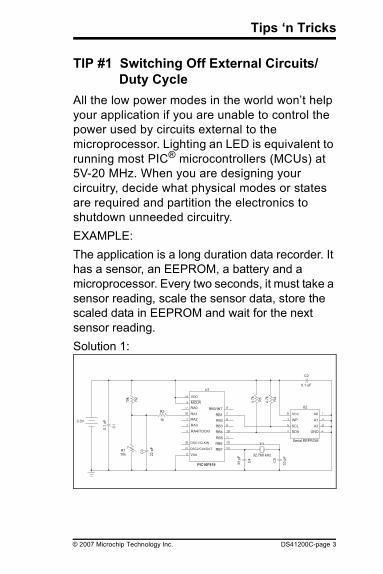
TIP #1 Switching Off External Circuits/Duty Cycle
All the low power modes in the world won’t help your application if you are unable to control the power used by circuits external to the microprocessor. Lighting an LED is equivalent to running most PIC® microcontrollers (MCUs) at 5V-20 MHz. When you are designing your circuitry, decide what physical modes or states are required and partition the electronics to shutdown unneeded circuitry.EXAMPLE:The application is a long duration data recorder. It has a sensor, an EEPROM, a battery and a microprocessor. Every two seconds, it must take a sensor reading, scale the sensor data, store the scaled data in EEPROM and wait for the next sensor reading.Solution 1:
PIC16F819
Serial EEPROM
U2
32.768 kHz
0.1 uF
VCC
C2
WP
SCL
SDA
A0
A1
A2
GND
33 p
F
33 p
F
C5
C4
Y1
R4
R5
4.7
k
4.7
k
U1
RB0/INT
RB1
RB2
RB3
RB4
RB5
RB6
RB7
VDD
MCLR
RA0
RA1
RA2
RA3
RA4/TOCKI
OSC1/CLKIN
OSC2/CLKOUT
VSS
R3
1k
22 p
F
C3R1
10k
R2
10k
C1
0.1
uF3.3V
© 2007 Microchip Technology Inc. DS41200C-page 3

Tips ‘n Tricks
TIP #1 Switching Off External Circuits/Duty Cycle (Cont.)
The system shown above is very simple and clearly has all the parts identified in the requirements. Unfortunately, it has a few problems in that the EEPROM, the sensor, and its bias circuit, are energized all the time. To get the minimum current draw for this design, it would be advantageous to shutdown these circuits when they are not required. See Solution 2.Solution 2:
In Solution 2, I/O pins are used to power the EEPROM and the sensor. Because the I/O pins can source 20 mA, there is no need to provide additional components to switch the power.
Serial EEPROM
U2
A0
A1
A2
GND
VCC
WP
SCL
SDA
0.1 uF
C233 p
F
C5
32.768 kHz
Y1
C4
33 p
F
R4
4.7
k
R5
4.7
k
PIC16F819
RB0/INT
RB1
RB2
RB3
RB4
RB5
RB6
RB7
VDD
RA0
RA1
RA2
RA3
RA4/TOCKI
OSC1/CLKIN
OSC2/CLKOUT
VSS
MCLR
1k
R3
R2
10k
22 p
F
C3R1
10k
C1
0.1
uF3.3V
U1
DS41200C-page 4 © 2007 Microchip Technology Inc.
Tips ‘n Tricks
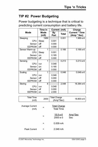
TIP #2 Power BudgetingPower budgeting is a technique that is critical to predicting current consumption and battery life.
ModeTime in Mode (mS)
Current (mA) Charge Current * Time
(Amp * Sec)By
Part Total
Sleeping 1989 0.001 1.989 e-6CPU Sleep 0.001
Sensor off 0.000EEPROM off 0.000
Sensor Warm-up 1 0.166 0.166 e-6CPU Sleep 0.001
Sensor on 0.165EEPROM off 0.000
Sensing 1 0.213 0.213 e-6CPU run 0.048
Sensor on 0.165EEPROM off 0.000
Scaling 1 0.048 0.048 e-6CPU run 0.048
Sensor off 0.000EEPROM off 0.000
Storing 8 2.048 16.384 e-6CPU run 0.048
Sensor off 0.000EEPROM on 2.000
Total Time 2000 Total Charge 18.800 e-6(mS) (Amp*Sec)
Average Current = Total Charge(mA) Total Time
= 18.8 e-6 Amp*Sec2000 e-3 Sec
= 0.009 mA
Peak Current = 2.048 mA
© 2007 Microchip Technology Inc. DS41200C-page 5
Tips ‘n Tricks
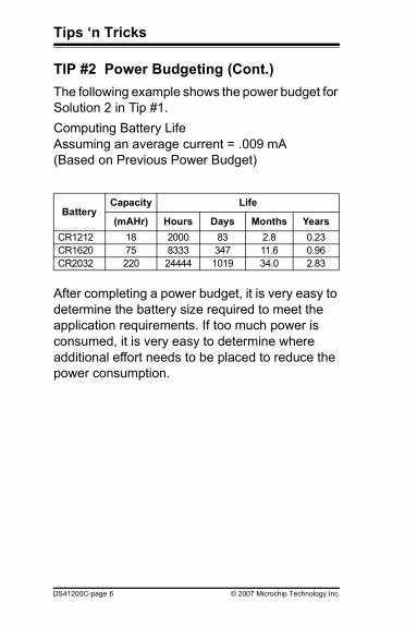
TIP #2 Power Budgeting (Cont.)The following example shows the power budget for Solution 2 in Tip #1.Computing Battery LifeAssuming an average current = .009 mA(Based on Previous Power Budget)
After completing a power budget, it is very easy to determine the battery size required to meet the application requirements. If too much power is consumed, it is very easy to determine where additional effort needs to be placed to reduce the power consumption.
BatteryCapacity Life
(mAHr) Hours Days Months YearsCR1212 18 2000 83 2.8 0.23CR1620 75 8333 347 11.6 0.96CR2032 220 24444 1019 34.0 2.83
DS41200C-page 6 © 2007 Microchip Technology Inc.
Tips ‘n Tricks
TIP #3 WDT Alternative Wake-upsMost applications control the power of the microprocessor by periodically going to Sleep. There are three ways to wake-up a sleeping PIC MCU:1. Receive an interrupt2. Wait for the Watchdog Timer3. Use an Ultra Low-Power Wake-Up (ULPWU)
peripheralThe new nanoWatt PIC16F/18F devices have a low current Watchdog Timer (WDT) that draws 2-3 μA. Additionally, the same devices can dynamically turn on/off the WDT for even more current savings.
© 2007 Microchip Technology Inc. DS41200C-page 7
Tips ‘n Tricks
TIP #4 Stretched DogThe Watchdog Timer (WDT) is commonly used for waking up a sleeping PIC MCU. The longer the PIC MCU stays asleep, the less power most applications will take. Therefore, it is appropriate to have a watchdog time-out duration that is long enough for your application. If the application requires data samples once per minute, then the Watchdog Timer should wake-up the PIC MCU once per minute. Newer PIC devices, such as the PIC18F1320 and PIC16F684, have an extended Watchdog Timer that allows the watchdog period to be stretched up to two minutes.
DS41200C-page 8 © 2007 Microchip Technology Inc.

Tips ‘n Tricks
TIP #5 Low Power Timer1 OscillatornanoWatt devices also offer a robust low power Timer1 oscillator which draws 2-3 μA. The Timer1 counter and oscillator can be used to generate interrupts for periodic wakes from Sleep and other power managed modes, and can be used as the basis for a real-time clock. The normal two second Timer1 overflow (using a 32.786 kHz watch crystal) can be extended to 16 seconds by selecting the 1:8 prescaler.Some nanoWatt devices can also use the Timer1 oscillator as the system clock source in place of the main oscillator on the OSC1/OSC2 pins. By reducing execution speed, total current consumption can be reduced.
© 2007 Microchip Technology Inc. DS41200C-page 9
Tips ‘n Tricks
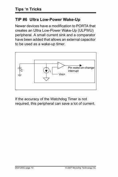
TIP #6 Ultra Low-Power Wake-UpNewer devices have a modification to PORTA that creates an Ultra Low-Power Wake-Up (ULPWU) peripheral. A small current sink and a comparator have been added that allows an external capacitor to be used as a wake-up timer.
If the accuracy of the Watchdog Timer is not required, this peripheral can save a lot of current.
VREF
C IPin wake-on-changeinterrupt
DS41200C-page 10 © 2007 Microchip Technology Inc.

Tips ‘n Tricks
TIP #7 Low Energy Power SuppliesDesigning the power supply for a low power device can be very tricky. There are many factors to consider including:1. Voltage/Current Requirements2. Battery Chemistry3. Battery Performance4. Battery Capacity5. Battery Size/Weight6. Battery CostBatteries come in all shapes, sizes and chemistries. High capacity batteries typically have a higher internal resistance, so they are less useful for high current applications. Batteries good for high current generally have lower capacity or greater weight than a similarly sized high resistance battery. Primary batteries (discharge only) also have much higher capacity than secondary batteries (rechargeable).If VDD must be kept constant, a battery chemistry with a flat discharge voltage may be used - two examples include LiMg (primary) and NiMH (secondary). If better control of a supply voltage is needed, a voltage regulator may be used.
© 2007 Microchip Technology Inc. DS41200C-page 11

Tips ‘n Tricks
TIP #8 Low Power Timer1Applications requiring Timer1 to have a clock crystal connected to its T1OSO and T1OSI pins must take PCB layout into consideration. The new low power Timer1 consumes very little current, and this sometimes makes the oscillator circuit sensitive to neighboring circuits. The oscillator circuit (crystal and capacitors) should be located as close as possible to the microcontroller. No circuits should be passing through the oscillator circuit boundaries. If it is unavoidable to have high-speed circuits near the oscillator circuit, a guard ring should be placed around the oscillator circuit and microcontroller pins similar to the figure below. Placing a ground plane under the oscillator components also helps to prevent interaction with high speed circuits.
OSC1
VSS
OSC2
RB7
RB6
RB5
DS41200C-page 12 © 2007 Microchip Technology Inc.
Tips ‘n Tricks
TIPS ‘N TRICKS WITH SOFTWARETo reduce costs, designers need to make the most of the available program memory in MCUs. Since program memory is typically a large portion of the MCU cost, optimizing the code helps to avoid buying more memory than needed. Here are some ideas that can help reduce code size.
© 2007 Microchip Technology Inc. DS41200C-page 13
Tips ‘n Tricks
TIP #9 Configuring Port PinsAll PIC MCUs have bidirectional I/O pins. Some of these pins have analog input capabilities. It is very important to pay attention to the signals applied to these pins so the least amount of power will be consumed.Unused Port Pins:
If a port pin is unused, it may be left unconnected but configured as an output pin driving to either state (high or low), or it may be configured as an input with an external resistor (about 10k Ohm) pulling it to VDD or VSS. If configured as an input, only the pin input leakage current will be drawn through the pin (the same current would flow if the pin was connected directly to VDD or VSS). Both options allow the pin to be used later for either input or output without significant hardware modifications.
Analog Inputs:A digital input pin consumes the least amount of power when the input voltage is near VDD or VSS. If the input voltage is near the midpoint between VDD and VSS, the transistors inside the digital input buffer are biased in a linear region and they will consume a significant amount of current. If such a pin can be configured as an analog input, the digital buffer is turned off, reducing both the pin current as well as the total controller current.
DS41200C-page 14 © 2007 Microchip Technology Inc.
Tips ‘n Tricks
TIP #9 Configuring Port Pins (Cont.)Analog inputs have a very high-impedance so they consume very little current. They will consume less current than a digital input if the applied voltage would normally be centered between VDD and VSS. Sometimes it is appropriate and possible to configure digital inputs as analog inputs when the digital input must go to a low power state.
Digital Outputs:There is no additional current consumed by a digital output pin other than the current going through the pin to power the external circuit. Pay close attention to the external circuits to minimize their current consumption.
© 2007 Microchip Technology Inc. DS41200C-page 15
Tips ‘n Tricks
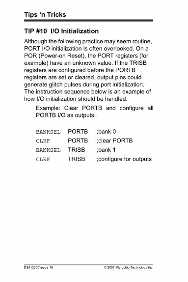
TIP #10 I/O InitializationAlthough the following practice may seem routine, PORT I/O initialization is often overlooked. On a POR (Power-on Reset), the PORT registers (for example) have an unknown value. If the TRISB registers are configured before the PORTB registers are set or cleared, output pins could generate glitch pulses during port initialization. The instruction sequence below is an example of how I/O initialization should be handled.
Example: Clear PORTB and configure allPORTB I/O as outputs:
BANKSEL PORTB ;bank 0CLRF PORTB ;clear PORTBBANKSEL TRISB ;bank 1CLRF TRISB ;configure for outputs
DS41200C-page 16 © 2007 Microchip Technology Inc.
Tips ‘n Tricks
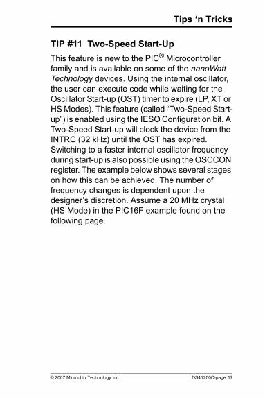
TIP #11 Two-Speed Start-UpThis feature is new to the PIC® Microcontroller family and is available on some of the nanoWatt Technology devices. Using the internal oscillator, the user can execute code while waiting for the Oscillator Start-up (OST) timer to expire (LP, XT or HS Modes). This feature (called “Two-Speed Start-up”) is enabled using the IESO Configuration bit. A Two-Speed Start-up will clock the device from the INTRC (32 kHz) until the OST has expired. Switching to a faster internal oscillator frequency during start-up is also possible using the OSCCON register. The example below shows several stages on how this can be achieved. The number of frequency changes is dependent upon the designer’s discretion. Assume a 20 MHz crystal (HS Mode) in the PIC16F example found on the following page.
© 2007 Microchip Technology Inc. DS41200C-page 17
Tips ‘n Tricks
TIP #11 Two-Speed Start-Up (Cont.)Tcy(Instruction Time) Instruction
ORG 0x05 ;Reset vector
125 μs @ 32 kHz BSF STATUS,RP0 ;bank1125 μs @ 32 kHz BSF OSCCON,IRCF2 ;switch to 1 MHz
4 μs @ 1 MHz BSF OSCCON,IRCF1 ;switch to 4 MHz
1 μs @ 4 MHz BSF OSCCON,IRCF0 ;switch to 8 MHz
500 ns application code500 ns application code… …... …(eventually OST Expires, 20 MHz crystal clocks the device)
200 ns application code… …... …
DS41200C-page 18 © 2007 Microchip Technology Inc.
Tips ‘n Tricks
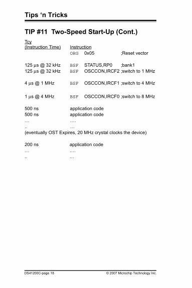
TIP #12 How To Use A Comparator Reference As A D/A
The voltage reference module normally used to set a reference for the comparators may be used as a simple D/A output with limited drive capability on pin RA2.Set the CVROE bit (CVRCON<6>), and configure the pin as an analog input.Due to the limited current drive capability, an external buffer must be used on the voltage reference output for external connections to VREF. See example below:
RA2
CVREFMODULE
R(1)
VOLTAGEREFERENCE
OUTPUTIMPEDANCE
OUTPUTCVREF
Note 1: R is dependent upon the Voltage ReferenceConfiguration CVRCON<3:0> and CVRCON<5>.
© 2007 Microchip Technology Inc. DS41200C-page 19
Tips ‘n Tricks
TIP #13 How To Detect A Loss of Crystal/Resonator Oscillator
The Fail-Safe Clock Monitor feature can be used to detect the loss of a crystal/resonator oscillator or other external clock source. When loss is detected, an internal clock source will provide system clocks, allowing for either a graceful shutdown or a “limp-along” mode if shutdown is not needed.Just set the FCMEN bit in the Configuration Word (CONFIG1H<6>). A higher “limp-along” speed can be selected by setting some of the IRCF bits (OSCCON<6:4>) before or after the loss occurs.
DS41200C-page 20 © 2007 Microchip Technology Inc.
Tips ‘n Tricks
TIP #14 Enabling IDLE ModesThe PIC18F nanoWatt family of devices feature multiple IDLE modes that can be used to reduce overall power consumption. By setting the IDLE bit (OSCCON<7>) and executing a SLEEP instruction, you can turn off the CPU and allow the peripherals to keep running. In these states, power consumption can be reduced by as much as 96%.
© 2007 Microchip Technology Inc. DS41200C-page 21
Tips ‘n Tricks
TIP #15 How To Eliminate An External Crystal, Resonator, or RC Timing Network
If a precision frequency clock is not required, use the internal clock source. It has better frequency stability than external RC oscillators, and does away with the external crystal, resonator, or RC timing network.The internal clock source can also generate one of several frequencies for use by the controller, allowing for reducing current demand by reducing the system frequency. When higher speed is required, it can be selected as needed under program control.
DS41200C-page 22 © 2007 Microchip Technology Inc.

Tips ‘n Tricks
TIPS ‘N TRICKS FOR HARDWARE/SOFTWARE COMBINEDThis section combines both hardware and software tips to help reduce external component count and reduce code size.
© 2007 Microchip Technology Inc. DS41200C-page 23
Tips ‘n Tricks
TIP #16 Clock Switching PIC16F Dual Clock
The PIC16F62X family of devices is equipped with a second low speed internal oscillator. This oscillator is available when the configured clock source is one of internal RC (INTRC), External RC* (EXTRC) or External Resistor** (ER) modes. The internal oscillator can be used to operate the microcontroller at low speeds for reduced power consumption. The actual speed of this oscillator is not calibrated, so expect 20%-40% variability in the oscillator frequency.To change oscillators, simply toggle bit 3 (OSCF) in the PCON register. When OSCF is clear, the low speed oscillator is used. When OSCF is set, the oscillator selected by the CONFIG bits is used.* EXTRC mode only available on A parts.** ER mode only available on the non-A parts.Newer devices have a multi-speed internal clock. They can switch from 8 MHz down to 31 kHz in 8 steps. The speed is selected using the OSCCON register.
DS41200C-page 24 © 2007 Microchip Technology Inc.
Tips ‘n Tricks
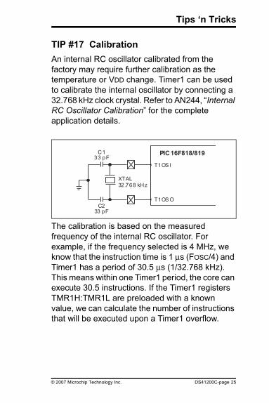
TIP #17 CalibrationAn internal RC oscillator calibrated from the factory may require further calibration as the temperature or VDD change. Timer1 can be used to calibrate the internal oscillator by connecting a 32.768 kHz clock crystal. Refer to AN244, “Internal RC Oscillator Calibration” for the complete application details.
The calibration is based on the measured frequency of the internal RC oscillator. For example, if the frequency selected is 4 MHz, we know that the instruction time is 1 μs (FOSC/4) and Timer1 has a period of 30.5 μs (1/32.768 kHz). This means within one Timer1 period, the core can execute 30.5 instructions. If the Timer1 registers TMR1H:TMR1L are preloaded with a known value, we can calculate the number of instructions that will be executed upon a Timer1 overflow.
PIC16F818/819
T1OS I
T1OS O
C233 pF
C133 pF
XTAL
32.768 kHz
© 2007 Microchip Technology Inc. DS41200C-page 25

Tips ‘n Tricks
TIP #17 Calibration (Cont.)This calculated number is then compared against the number of instructions executed by the core. With the result, we can determine if re-calibration is necessary, and if the frequency must be increased or decreased. Tuning uses the OSCTUNE register, which has a ±12% tuning range in 0.8% steps.
Visit the low power design center at www.microchip.com for additional design resources.
DS41200C-page 26 © 2007 Microchip Technology Inc.

Tips ‘n Tricks
© 2007 Microchip Technology Inc. DS41200C-page 27
NOTES:

Tips ‘n Tricks
DS41200C-page 28 © 2007 Microchip Technology Inc.
NOTES:
© 2007 Microchip Technology Inc. DS41200C-page 29
Information contained in this publication regarding deviceapplications and the like is intended through suggestion only andmay be superseded by updates. It is your responsibility to ensurethat your application meets with your specifications. No represen-tation or warranty is given and no liability is assumed by MicrochipTechnology Incorporated with respect to the accuracy or use ofsuch information, or infringement of patents or other intellectualproperty rights arising from such use or otherwise. Use ofMicrochip’s products as critical components in life support systemsis not authorized except with express written approval byMicrochip. No licenses are conveyed, implicitly or otherwise, underany intellectual property rights.The graphics in this document are for illustration only. Microchipreserves the right to modify the contents of its developmentsystems.TrademarksThe Microchip name and logo, the Microchip logo, Accuron, dsPIC, KEELOQ, KEELOQ logo, microID, MPLAB, PIC, PICmicro, PICSTART, PRO MATE, PowerSmart, rfPIC, and SmartShunt are registered trademarks of Microchip Technology Incorporated in the U.S.A. and other countries.AmpLab, FilterLab, Linear Active Thermistor, Migratable Memory, MXDEV, MXLAB, PS logo, SEEVAL, SmartSensor and The Embedded Control Solutions Company are registered trademarks of Microchip Technology Incorporated in the U.S.A.Analog-for-the-Digital Age, Application Maestro, CodeGuard, dsPICDEM, dsPICDEM.net, dsPICworks, ECAN, ECONOMONITOR, FanSense, FlexROM, fuzzyLAB, In-Circuit Serial Programming, ICSP, ICEPIC, Mindi, MiWi, MPASM, MPLAB Certified logo, MPLIB, MPLINK, PICkit, PICDEM, PICDEM.net, PICLAB, PICtail, PowerCal, PowerInfo, PowerMate, PowerTool, REAL ICE, rfLAB, rfPICDEM, Select Mode, Smart Serial, SmartTel, Total Endurance, UNI/O, WiperLock and ZENA are trademarks of Microchip Technology Incorporated in the U.S.A. and other countries.SQTP is a service mark of Microchip Technology Incorporated in the U.S.A.All other trademarks mentioned herein are property of their respective companies.© 2007, Microchip Technology Incorporated, Printed in the U.S.A., All Rights Reserved.
Printed on recycled paper.

M
DS41200C-page 30 © 2007 Microchip Technology Inc.
Worldwide Sales and Service
*DS41200C*
AMERICASCorporate OfficeTel: 480-792-7200 Technical Support: http://support.microchip.comAtlantaTel: 678-957-9614BostonTel: 774-760-0087ChicagoTel: 630-285-0071DallasTel: 972-818-7423DetroitTel: 248-538-2250KokomoTel: 765-864-8360Los AngelesTel: 949-462-9523Santa ClaraTel: 408-961-6444TorontoTel: 905-673-0699ASIA/PACIFICAustraliaTel: 61-2-9868-6733China-BeijingTel: 86-10-8528-2100China-ChengduTel: 86-28-8665-5511China-FuzhouTel: 86-591-8750-3506
China-Hong Kong SARTel: 852-2401-1200China-QingdaoTel: 86-532-8502-7355China-ShanghaiTel: 86-21-5407-5533 China-ShenyangTel: 86-24-2334-2829China-ShenzhenTel: 86-755-8203-2660China-ShundeTel: 86-757-2839-5507China-WuhanTel: 86-27-5980-5300China-XianTel: 86-29-8833-7250India-BangaloreTel: 91-80-4182-8400India-New DelhiTel: 91-11-4160-8631India-PuneTel: 91-20-2566-1512Japan-YokohamaTel: 81-45-471- 6166Korea-GumiTel: 82-54-473-4301Korea-SeoulTel: 82-2-554-7200Malaysia-PenangTel: 60-4-646-8870
Philippines-ManilaTel: 63-2-634-9065SingaporeTel: 65-6334-8870Taiwan-Hsin ChuTel: 886-3-572-9526Taiwan-KaohsiungTel: 886-7-536-4818Taiwan-TaipeiTel: 886-2-2500-6610Thailand-BangkokTel: 66-2-694-1351EUROPEAustria-WeisTel: 43-7242-2244-39Denmark-CopenhagenTel: 45-4450-2828France-ParisTel: 33-1-69-53-63-20Germany-MunichTel: 49-89-627-144-0Italy-MilanTel: 39-0331-742611Netherlands-DrunenTel: 31-416-690399Spain-MadridTel: 34-91-708-08-90UK-WokinghamTel: 44-118-921-5869
12/08/06
Microchip received ISO/TS-16949:2002 certification for its worldwide headquarters, design and wafer fabrication facilities in Chandler and Tempe, Arizona, Gresham, Oregon and Mountain View, California. The Company’s quality system processes and procedures are for its PIC® MCUs and dsPIC® DSCs, KEELOQ® code hopping devices, Serial EEPROMs, microperipherals, nonvolatile memory and analog products. In addition, Microchip’s quality system for the design and manufacture of development systems is ISO 9001:2000 certified.


Microchip Technology Inc.2355 W. Chandler Blvd. • Chandler, AZ 85224 U.S.A.
Phone: 480-792-7200 • Fax: 480-792-9210www.microchip.com
© 2007, Microchip Technology Inc., 4/07 DS41200C
*DS41200C*