md of bonnyville, alberta contract documentssedesign.ca/wp-content/uploads/2018/02/ardmore... · md...
TRANSCRIPT

ARDMORE PHASE 5 UNDERGROUND MD OF BONNYVILLE, ALBERTA
CONTRACT DOCUMENTS
Municipal District of Bonnyville No. 87
S E D E S I G N A N D C O N S U L T I N G I N C .


MD-0033
INVITATION TO TENDER
MUNICIPAL DISTRICT OF BONNYVILLE NO. 87 ARDMORE PHASE 5 UNDERGROUND
Sealed tenders marked "Municipal District of Bonnyville No. 87, Ardmore Phase 5 Underground”, will be received at offices of the Municipal District of Bonnyville Public Works up to 10:00 A.M, 27 February 2018. The work generally involves the construction of:
Ardmore Phase 5 Underground 1. Remove and Salvage existing road structure (milling) 8,175 m2
2. Remove and dispose of existing sewer 1,010 l.m.
3. Remove and dispose of existing water main 925 l.m.
4. Remove and dispose of existing manhole 11 ea
5. Remove and dispose of existing culverts 22 ea
6. Trenching & Backfilling for sewer 1,800 l.m.
7. Trenching & Backfilling for water 975 l.m
8. Supply and Install 250mm sanitary sewer 225 l.m.
9. Supply and Install 200mm sanitary sewer 720 l.m.
10. Supply and Install 1200mm sanitary manholes 9 ea
11. Supply and Install 375mm storm sewer 195 l.m.
12. Supply and Install 450mm storm sewer 90 l.m.
13. Supply and Install 600mm storm sewer 290 l.m.
14. Supply and Install 750mm storm sewer 285 l.m.
15. Supply and Install storm manholes 13 ea.
16. Supply and Install Catch Basins 17 ea.
17. Supply and Install 250mm DR18 C900 PVC water 510 l.m
18. Supply and Install 200mm DR18 C900 PVC water 425 l.m
19. Supply and install 150mm DR18 C900 PVC water 45 l.m.
20. Supply and Install water valves 15 ea.
21. Supply and Install Hydrants c/w valves 7 ea.
22. Supply and Install culverts 300mm 22 ea
23. CCTV sewer inspection 1,800 l.m.
24. Single family service connections (water & sanitary) 51 ea
25. Standard Subgrade Preparation to 300mm 450 m2
26. Standard Subgrade Preparation to 200mm 8,850 m2
27. Supply and Place 300mm Depth Crushed Gravel Base 450 m2
28. Supply and Place 75mm Depth Crushed Gravel Base 8,850 m2
29. 140 mm Depth Hot Mix Asphalt 450 m2 Tender documents may be obtained from the office of the Engineer on or after 2:00 PM 6
th February,
2018 upon payment of a non-refundable deposit of $150.00 paid by cash or a cheque made payable to the Engineer. Documents can be downloaded for free at www.sedesign.ca website or from the Municipal District of Bonnyville website at http://md.bonnyville.ab.ca/bids.aspx.

MD-0033
Tenders must be accompanied by a Bid Bond or Certified Cheque in the amount of 10% of the tender amount and made payable to the Municipal District of Bonnyville No. 87. The lowest or any tender will not necessarily be accepted. The prices tendered will not be the only consideration in evaluating whether to accept the tender from a qualified tenderer. Experience of personnel, nature of equipment used, proposed construction scheduling and references on previous work undertaken by the tenderer will also be considerations.
Mr. Mario Gagnon, PEng SE Design and Consulting Inc. 713 Lakeshore Drive Cold Lake, Alberta T9M 0C4
PHONE: 780-594-5380 FAX: 780-594-4486 Mr. Darcy Zelisko Director of Transportation and Utilities Municipal District of Bonnyville No. 87 61330 RR 455 Bag 1010 BONNYVILLE, Alberta, T9N 2J7 PHONE:(780) 826-3951

SE DESIGN AND CONSULTING INC. -i- MD-0033
Ardmore Phase 5 Underground
Municipal District of Bonnyville
TABLE OF CONTENTS NO.OF PAGES
INSTRUCTIONS TO TENDERERS 7
CONTRACT AGREEMENT 3
CONTRACT TENDER FORM 4
GENERAL CONDITIONS - TABLE OF CONTENTS 1
GENERAL CONDITIONS 35 SPECIFICATIONS SECTION NO. TITLE 01000 SPECIAL PROVISIONS 9 01005 GENERAL INSTRUCTIONS 5 01501 GENERAL PROJECT REQUIREMENTS 12 01502 TRAFFIC ACCOMODATION 4 01503 SAFEGUARDING UTILITY INSTALLATIONS 5 01545 SAFETY REQUIREMENTS 4 01560 ENVIRONMENTAL PROTECTION 3 02000 SPECIAL PROVISIONS 5 02070 PROTECTION AND REMOVALS 2 02225 AGGREGATES – GENERAL 4 02311 SITE GRADING 4 02315 TRENCHING AND BACKFILLING 12 02340 SUBGRADE CONSTRUCTION 6 02434 PIPE CULVERTS 5 02511 WATER MAINS 14 02585 BUILDING SERVICES 9 02630 SEWER MAINS 14 02721 GRANULAR BASE COURSE 4 02741 HOT MIX ASPHALT PAVEMENT 12 02745 PRIME AND TACK COATS 4 02770 CONCRETE 10 02911 TOPSOIL REPLACEMENT 2 02921 HYDROSEEDING 4 02966 PAVEMENT SURFACE CLEANING 1
APPENDIX PRIME CONTRACTOR AGREEMENT PERMISSION FOR LAND USE FORM GEOTECHNICAL REPORT

SE DESIGN AND CONSULTING INC. - i -
INSTRUCTIONS TO TENDERERS
TABLE OF CONTENTS
Article Description Page No.
1 Tender Submission 1
2 Tender Document Deposit 1
3 Examination of Documents and Site 1
4 Tenderer's Questionnaire 2
5 Subcontractors 2
6 Materials 2
7 Tender Price 2
8 Bid Bond or Certified Cheque 3
9 Surety Bonding and Insurance 3
10 Revision of Tender 4
11 Withdrawal of Tender 4
12 Tender Rejection 4
13 Alternative Materials and Equipment 4
14 Tender Evaluation 5
15 Award 7

INSTRUCTION TO TENDERERS
SE DESIGN AND CONSULTING INC. - 1 -
1.0 Tender Submission
.1 Submit tender in sealed, clearly marked envelope. .2 Submit on Contract Tender Forms provided. Two copies are
provided with the Tender documents. Retain one copy for rough copy or records.
.3 All bid prices and other information required in the Tender Form to
be completed. .4 Alternations to the Tender Form or conditional letters may make
tender submission liable to rejection. .5 Sign Tender Form and provide business address and telephone
number. .6 Only duly authorized official may sign Tender Form. .7 Tenders of corporations must be sealed with the corporate seal.
2.0 Tender Document Deposit
.1 The Tender deposit will be non-refundable.
3.0 Examination of Documents and Site
.1 Carefully examine the Contract Documents and the site of the
works prior to submitting Tender. .2 No claims for misunderstanding with respect to the conditions
imposed by the Contract will be considered. .3 The Contract Documents contain a section referred to as Special
Provisions which contain any changes or modifications to any specific sections of the Contract Documents.
.4 Changes to the Contract Documents which occur during the tender
period will be made by the issuance of Addenda.

INSTRUCTION TO TENDERERS
SE DESIGN AND CONSULTING INC. - 2 -
.5 Report to the Engineer any discrepancies in or omissions from the
drawings and other documents. .6 No verbal agreement or conversation with any officer, agent or
employee of the Owner or the Engineer shall affect or modify any of the terms or obligation herein stated.
4.0 Tenderer's Questionnaire
.1 Complete questionnaire provided with Tender Documents
identifying the necessary equipment and personnel to carry out the work satisfactorily within the time stated in the Tender Form.
.2 Failure to complete this questionnaire may result in tender
rejection.
5.0 Subcontractors
.1 Submit names of all subcontractors that will be employed on the
work. .2 Changes in subcontractors will not be permitted without the written
consent of the Engineer.
6.0 Materials
.1 Submit names of materials suppliers, trade and brand names of
materials. .2 Changes will not be permitted without written consent of the
Engineer.
7.0 Tender Price
.1 Complete unit prices where required on Tender Form. .2 Extend product of unit prices and tender quantities and provide
total tender amount. .3 Unit prices will govern where there is a discrepancy between unit
prices and extended totals. .4 Engineer will correct errors in extended totals where these occur.

INSTRUCTION TO TENDERERS
SE DESIGN AND CONSULTING INC. - 3 -
8.0 Bid Bond or Certified Cheque
.1 Provide with tender submission a Bid Bond or Certified Cheque in
the amount of 10% of the tender prices. .2 Bid Bond must be issued by a Surety company licensed to conduct
business in Alberta.
.3 A portion of or the entire amount of the Bid Bond or certified cheque will be forfeited to the Owner in the event the Tenderer fails to execute the Contract agreement or to provide the stipulated Surety Bonds.
.4 Amount retained by Owner will be equal to the difference between
the Tenderer's price and that price which the Owner may legally contract with another party to perform the work.
.5 Bid Bonds and certified cheques furnished by unsuccessful
tenderers will be returned to them as soon as possible after Contract is awarded or as otherwise determined.
9.0 Surety Bonding and Insurance
.1 To ensure the faithful execution and proper fulfillment of this Contract, the
Contractor shall provide the Owner with the following bonds at the time of his execution of the Contract Agreement:
.1 A Performance Bond in the amount of fifty percent (50%) of the Contract Price covering the faithful performance of the Contract including the corrections after completion provided for in Article 27 hereof, and the payment of all obligations arising under the Contract.
.2 A Labour and Material Payment Bond in the amount of fifty
percent (50 %) of the Contract Price covering the payment of all labour and material used or reasonably required in the performance of the Contract.
.2 These bonds must be issued by a surety company licensed to conduct
business in the province or territory wherein the Work is located and shall be provided on forms acceptable to the Engineer and compatible with the forms contained within the Contract Documents.
.3 If awarded Contract, provide certification of insurance coverage as required by General Conditions.
.4 Provide bonding and certification of insurance coverage with the executed

INSTRUCTION TO TENDERERS
SE DESIGN AND CONSULTING INC. - 4 -
Contract Agreement within the (10) days after being notified of award of Contract.
10.0 Revision of Tender
.1 Revisions to the tender by FAX 780-826-5064 will be accepted if received prior to the specified closing time to the office of the Municipal District of Bonnyville (Public Works) on the date the tender close.
.2 Faxed tender will be accepted only if the original of the tender
security is delivered to the office of the Municipal District of Bonnyville prior to the specified closing time on the date the tenders close.
11.0 Withdrawal of Tender
.1 Tenders may be withdrawn by the Tenderer any time prior to one
(1) hour of the time set for the closing of the tenders.
12.0 Tender Rejection
.1 Owner reserves the right to reject any or all tenders. .2 The lowest tender will not necessarily be accepted. .3 Any tender may be rejected which is incomplete, obscure or
irregular, which has erasures or corrections in the Tender Form, in which prices are omitted or are unbalanced, or which has insufficient or irregular surety.
13.0 Alternative Materials and Equipment
.1 Contractor must construct the work using the product type and brand specified unless alternative products are approved by the Engineer.
.2 Contractor to submit alternate products 7 days before tender
closing for engineer review. Alternate products submitted for engineer review 6 days before tender closing will not be accepted.
.3 The Engineer will evaluate alternative products an issue an
addendum if alternate product is approved.

INSTRUCTION TO TENDERERS
SE DESIGN AND CONSULTING INC. - 5 -
14.0 Tender Evaluation
.1 The Municipal District of Bonnyville’s tendering processes aim is to ensure that the most suitable contractor is selected for each project.
.2 A tender evaluation process using weighted criteria is adopted to determine the tender that offers the best value. This process is utilized where the performance of the contractor is of crucial importance to achieving the required outcome.
.3 The weighted criteria method of tender evaluation requires that selection criteria, in addition to price, are included in tender documents and form part of the tender assessment process. A system of weighting the selection criteria is used to compare tenders and identify the tenderer with the best performance record in terms of time, cost and value for money. .4 The selection criteria are as follows:
Relevant Experience (15%): Previous experience of the tenderer needs to be assessed in relation to the fields of expertise required to achieve the intended outcomes of the project. Recent experience is more valuable than historic experience. The company’s previous experience in technical areas comparable to the tendered project, the scale of past projects and the role undertaken within those projects will be considered as well as overall safety record of the company. Contractor is required to fill in the form titled “Relevant Experience” for three (3) projects that is included with the tender form. Failure to provide the information on three projects will result in a score of zero. For example if contractor provides information on two projects, they will get 2/3 of the points.
This criteria is given a point score from 0 (poor) to 10 (excellent). The weighted score is calculated by multiplying the score by the weight. In example below, the weighted score for Tenderer #1 is calculated as 9x15% = 1.35.
Past Performance (15%) : The tendering organisation's performance in completing past projects to the quality standards required, time performance, within budget, claims history, project management, will be assessed. Contractor is required to fill in the form titled “Past Performance” for three (3) projects that is included with the tender form. This criteria is given a point score from 0 (poor) to 10 (excellent). The weighted score is calculated by multiplying the score by the

INSTRUCTION TO TENDERERS
SE DESIGN AND CONSULTING INC. - 6 -
weight. In example below, the weighted score for Tenderer #1 is calculated as 7x15% = 1.05. Failure to provide the information on three projects will result in a score of zero. For example if contractor provides information on two projects, they will get 2/3 of the points.
Price (70%): The price is the sum that the Owner would be required to pay to the tenderer for the work or service provided. This must include all costs over the duration of the contract. The prices will be graded on the following valuation scale:
o Low bid price shall be given 70 points; o bid price within or equal to 0.5% of the low bid price shall be
given 67.5 points; o bid price greater than 0.5% but less than or equal to 2% of
the low bid price shall be given 65.5 points; o bid price greater than 2% but less than or equal to 5% of the
low bid price shall be given 63.5 points; o bid price greater than 5% but less than or equal to 10% of
the low bid price shall be given 61 points; o bid price greater than 10% shall be given 57 points;
The following table is an example of a tender evaluation:
Scoring Price Example for Tenderer #2 = $1,333,000 - $1,282,000 = 3.8% = 63.5 points $1,333,000
Tenderer Tenders (in ascending order)
Percentage Scoring Price
Tenderer #1 $1,282,000.00 70
Tenderer #2 $1,333,000.00 3.8% 63.5
Tenderer #3 $1,925,000.00 33.4% 57
Total Scores
Tenderer #1 Tenderer #2 Tenderer #3 Relevant Experience, weight 15% Weighted
Score 1.35 1.2 1.35
Past Performance, weight 15% Weighted Score
1.05 1.2 1.35
Total non-price criteria 2.4 2.4 2.7
Scoring non-price 2.4x10/2.7 2.4x10/2.7 10
8.89 8.89 10
Weighted non-price 30% 2.67 2.67 3.0
Scoring Price 70 63.5 57
Weighted price 70% 49 44.45 39.9
Totals 100% 51.67 47.12 42.90

INSTRUCTION TO TENDERERS
SE DESIGN AND CONSULTING INC. - 7 -
15.0 Award
.1 Owner or the Consultant on behalf of the Owner will issue in writing a Notice of Award to the successful Tenderer.
.2 Notice will be given not later than sixty (60) days following the
closing of tenders.

SE DESIGN AND CONSULTING INC. 1
CONTRACT AGREEMENT THIS CONTRACT AGREEMENT made in triplicate on the day of 2018 by and between: Municipal District of Bonnyville Hereinafter called the "Owner" and
Hereinafter called the "Contractor" The Owner and the Contractor agree as follows: 1. SCOPE OF THE WORK
The Contractor agrees to furnish all the material (except as otherwise specified to be supplied by others) together with all of the equipment and labour and transportation necessary to perform the entire Work described in the Contract Documents for the entire project entitled: Ardmore Phase 5 Underground MD of Bonnyville, AB which Contract Documents have been prepared by SE Design and Consulting Inc. The Invitation to Tender, Tender Form, and drawings incorporated herein are included therein. The Contract Documents are an integral part of this Contract Agreement.
2. CONFLICTS AND PRECEDENCE OF DOCUMENTS
In the case of any inconsistency or conflict between the provisions of the separate parts of the Contract Documents, the separate parts shall take precedence and govern in accordance with the following order:
1. Contract Agreement 2. Invitation to Tender – SE Design and Consulting Inc. 3. Specifications – Municipal District of Bonnyville 4. Drawings – SE Design and Consulting Inc. 5. Tender Form – SE Design and Consulting Inc.

SE DESIGN AND CONSULTING INC. 2
CONTRACT AGREEMENT
3. TIME OF COMPLETION
The work to be performed under this Contract shall be fully completed by the 30th day of October, 2018. Contractor to note that all work near and around the school zone must be completed between June 30th 2018 – August 28th 2018. Contractor to plan their work accordingly
and identify this specific area in their construction schedule. The contractor will perform his work faithfully and diligently to complete the project within this timeframe.
4. PAYMENT
The Owner shall pay the Contractor for the performance of the Contract in current funds, at the prices named in the Contract Tender Form. An acceptable invoice must be submitted to the engineer within sixty (60) days from payment cut off period or payment will not be made to the contractor. Payment cutoff period will be at the end of every month during which the Work was performed. Payment will be made within 30 days of receipt of an acceptable invoice. Ten percent (10%) of the value of work performed will be withheld from payment to the Contractor in accordance with the Builders’ Lien Act and will be released to the Contractor in accordance with the provisions of the Act, upon completion of the entire project including correction of deficiencies and upon submission by the Contractor of the following documentation: 1. Letter from the Contractor stating that he has submitted all claims for payment
related to the contract. 2. Letter of Clearance from the Workers’ Compensation Board. Statutory
Declaration from the Contractor stating that there are no outstanding claims for payment related to the project from suppliers, subcontractors, labourers or any other parties affected by the work
5. INSURANCE
Prior to commencing construction provide certification of insurance coverage for personal injury and property damage (minimum $2,000,000.00).
6. WRITTEN NOTICE
Written notice shall be deemed to have been duly served if delivered in person to the individual, or to a member of the firm, or to an officer of the corporation for which it is intended, or if delivered or sent prepaid registered mail to its business address, and it shall be deemed received on the day next following the day of mailing.

SE DESIGN AND CONSULTING INC. 3
CONTRACT AGREEMENT
IN WITNESS WHEREOF the Parties have executed this Contract Agreement, on the day and year first above written.
SIGNED, SEALED AND DELIVERED in the presence of: Witness to the Signature of the MD of Bonnyville MUNICIPAL DISTRICT OF BONNYVILLE Name: Name: Signature:__________________________ Signature:___________________________ Title:
Name: ____________________________ Name: Signature:__________________________ Signature:___________________________ Title:
Witness to the Signature of the Contractor CONTRACTOR Name: Name: Signature:__________________________ Signature:___________________________ Title:
SEAL
Name: _____________________________ Name: Signature:___________________________ Signature:___________________________ Title:

SE DESIGN AND CONSULTING INC.
CONTRACT TENDER FORM
TENDER OF:
NAME
ADDRESS
TO: MUNICIPAL DISTRICT OF BONNYVILLE NO.87
61330 RR 455, Bag 1010
BONNYVILLE, ALBERTA
T9N 2J7
GENTLEMEN:
The undersigned Tenderer, having carefully examined the Contract Documents and the locality of the proposed work, and having full knowledge of the work required and of the materials to be furnished and used, hereby agrees to provide all necessary materials, supervision, labour and equipment and perform and complete all work and fulfill everything as set forth and in strict accordance with the Contract Documents and Addenda numbered for the prices stated in the Tender Form Schedule of Quantities and Prices. The undersigned agree also:
1. That the Owner is not obligated to accept this tender. 2. That this tender is made without any connection, knowledge, comparison of figures or
arrangements with any other company, firm, or person making a tender for the same work.
3. That no person or firm other than the Tenderer whose signature is affixed below has any interest in this tender or in the proposed Contract.
4. That this tender is irrevocable for sixty (60) days after tender submission or closing time.
5. To execute the Contract Agreement within ten (10) days of the date of the Notice of Award of the
Contract, such time limit being extended only on the written approval of the Owner.

SE DESIGN AND CONSULTING INC.
CONTRACT TENDER FORM
6. To commence and actively proceed with the work within seven (7) days of the date of the Notice
to Proceed, and to complete all work under the Contract within the time period indicated in the Contract Agreement subject to the provisions of Article 41 of the General Conditions for extension of Contract time.
7. The work to be performed under this Contract shall be fully completed by
the 30th day of October, 2018.
8. Contractor to note that all work near and around the school zone must be completed between
June 30th 2018 – August 28
th 2018. Contractor to plan their work accordingly and identify this
specific area in their construction schedule.
9. The contractor will perform his work faithfully and diligently to complete the project within this timeframe.
10. That should he fail to complete the work within the contract time, he shall be required to
compensate the Owner in accordance with the Contract Documents.
11. That no bonus will be allowed for completion in less time than that stated above.
12. To do all extra work not reasonable inferable from the specifications or drawings but called for in writing by the Engineer and to accept as full compensation therefore payment in accordance with the provisions of Article 39 of the General Conditions.
13. That the estimate of quantities shown in the Tender Form serves only to provide a basis for
comparing tenders and that the actual job quantities will not necessarily correspond with the quantities shown in the Tender Form, and further, that the Owner has the right to increase or decrease the quantities in any or all items and to eliminate schedules or items entirely from the work. If the quantity is reduced or deleted from the work, the Contractor will not be financially compensated for items such as: overhead cost, admin fees, equipment cost, labour, indirect cost, profit etc. If the quantity is increased, the Contractor will be paid as per his unit price in the contract.
14. That payment for the work done will be made on the basis of the quantities measured by the
Engineer and at the prices shown in the Tender Form which shall be compensation in full for the work done under the terms of the Contract.
15. That the Bidder has drawn his conclusions from the data provided in the geotechnical coring results within the Contract and has not relied on the opinions or recommendations provided.

SE DESIGN AND CONSULTING INC.
CONTRACT TENDER FORM
This tender is executed under seal at , this day of , 20 .
NAME OF FIRM:
ADDRESS:
FOR INDIVIDUAL OR PARTNERSHIP: SIGNED, SEALED AND DELIVERED BY (TENDERER - PLEASE PRINT) (SIGNATURE OF TENDERER) in the presence of: NAME:
ADDRESS:
SEAL
OCCUPATION: FOR LIMITED COMPANY: The Corporate Seal of: (TENDERER - PLEASE PRINT) (SIGNATURE OF TENDERER) was hereto affixed in the presence (APPOINTMENT) SEAL (APPOINTMENT) NOTE: If the Tenderer is by a joint venture, add additional forms of execution for each member
of the joint venture in the appropriate form or forms as above.

MUNICIPAL DISTRICT OF BONNYVILLE No. 87
ARDMORE, ALBERTA
PHASE V - UNDERGROUND
SCHEDULE OF QUANTITIES
Item Spec. No. Description
Unit
Price
$
Contract
Value
$
SCHEDULE 1.0 - GENERAL
1.1 1501 General project requirements 1 l.s.
1.2 1502 Traffic accomodation 1 l.s.
TOTAL FOR SCHEDULE 1.0
SCHEDULE 2.0 - REMOVALS
2.1 2000Removal and salvage of existing road structure (millings) to
150mm depth c/w stockpiling at designated location on site8,175 m
2
2.2 2000 Removal and dispose of existing concrete 140 m2
2.3 2070 Remove and dispose existing culverts 22 ea.
2.4 2070 Remove and dispose of existing sanitary sewer 880 l.m.
2.5 2070 Remove and dispose of existing sanitary manhole 8 ea.
2.6 2070 Remove and dispose of existing water main 925 l.m.
2.7 2070 Remove and dispose of existing stormwater main 130 l.m.
2.8 2070 Remove and dispose of existing stormwater manhole 3 ea.
2.9 2000Removal and dispose existing soil cement from road structure to
250mm depth200 m
2
NOTE: The specitication number refers to specification covering measurements and payment of the respective item
Quantity and/or
Unit
SE DESIGN AND CONSULTING INC.
Project: MD-0033 Page 1 of 7

MUNICIPAL DISTRICT OF BONNYVILLE No. 87
ARDMORE, ALBERTA
PHASE V - UNDERGROUND
SCHEDULE OF QUANTITIES
Item Spec. No. Description
Unit
Price
$
Contract
Value
$
NOTE: The specitication number refers to specification covering measurements and payment of the respective item
Quantity and/or
Unit
2.10 2070 Removal of bushes and re-grade existing ditch 100 l.m.
TOTAL FOR SCHEDULE 2.0
SCHEDULE 3.0 - SANITARY SEWER SERVICING
3.1 2315Trenching & backfilling to 98% StandardProctor Density including
disposal of surplus trench excavation.950 l.m.
3.2 2630 Supply and install 200 mm sanitary sewer 720 l.m.
3.3 2630 Supply and install 250 mm sanitary sewer 225 l.m.
3.4 2630 Tie sanitary to existing sanitary manhole 3 ea.
3.6 2630Supply and install 1200 mm sanitary manhole c/w NF-80 frame &
cover9 ea.
3.7 2630 Supply and install 250mm plug 1 ea.
3.8 2630 Supply and install frost box installation 220 l.m.
3.9 2630 CCTV Sewer inspection 950 l.m.
TOTAL FOR SCHEDULE 3.0
SCHEDULE 4.0 - WATER SERVICING
4.1 2315Trenching & backfilling to 98% Standard Proctor Density including
disposal of surplus trench excavation.975 l.m.
4.2 2511 Supply and install 250 mm DR18 C900 PVC water 510 l.m.
SE DESIGN AND CONSULTING INC.
Project: MD-0033 Page 2 of 7

MUNICIPAL DISTRICT OF BONNYVILLE No. 87
ARDMORE, ALBERTA
PHASE V - UNDERGROUND
SCHEDULE OF QUANTITIES
Item Spec. No. Description
Unit
Price
$
Contract
Value
$
NOTE: The specitication number refers to specification covering measurements and payment of the respective item
Quantity and/or
Unit
4.3 2511 Supply and install 200 mm DR18 C900 PVC water 425 l.m.
4.4 2511 Supply and install 150 mm DR18 C900 PVC water 45 l.m.
4.5 2511 Tie to existing watermain 3 ea.
4.6 2511 Supply and install 200 mm valve 5 ea.
4.7 2511 Supply and install 250 mm valve 9 ea.
4.8 2511 Supply and install temporary valve V5-11 - 200mm 1 ea.
4.9 2511Remove temporary valve V5-11 off existing watermain and place
on proposed watermain1 ea.
4.10 2511 Supply and install fittings
.1 250x200 Tee 3 ea.
.2 200mm, 22.5 degree bend 2 ea.
.3 250mm, 22.5 degree bend 4 ea.
.4 250x150 Tee 2 ea.
.5 200x150 Tee 4 ea.
.6 200x200 Tee 1 ea.
4.11 2511 Supply and install hydrant c/w valve 6 ea.
4.12 2511 Supply and install 250mm plug 1 ea.
4.13 2511 Supply and install yard hydrant c/w valve 1 ea.
SE DESIGN AND CONSULTING INC.
Project: MD-0033 Page 3 of 7

MUNICIPAL DISTRICT OF BONNYVILLE No. 87
ARDMORE, ALBERTA
PHASE V - UNDERGROUND
SCHEDULE OF QUANTITIES
Item Spec. No. Description
Unit
Price
$
Contract
Value
$
NOTE: The specitication number refers to specification covering measurements and payment of the respective item
Quantity and/or
Unit
4.14 2511 Supply and install 200x250mm reducer 1 ea.
TOTAL FOR SCHEDULE 4.0
SCHEDULE 5.0 - SINGLE FAMILY SERVICE CONNECTIONS
5.1 2585Supply and install 100 mm DR28 PVC sanitary service to property
line570 l.m.
5.2 2585 Supply and install 100 mm sanitary service tee-wye 51 ea.
5.3 2585 Supply and install 20 mm water service to property line 515 l.m.
5.4 2585 Supply and install 50 mm water service to property line 75 l.m.
5.5 2585Supply and install service connection to water main c/w
corporation main stop51 ea.
5.6 2585 Supply and install service connection to water main 1 ea.
5.7 2585 Supply and install curb stop (incl. service box) 51 ea.
5.8 2585Supply and Install sanitary inspection chambers with cast iron
covers51 ea.
5.9 2315Trenching & backfilling to 98% Std. Proctor Density including
disposal of surplus trench excavation for single services.660 l.m
TOTAL FOR SCHEDULE 5.0
SE DESIGN AND CONSULTING INC.
Project: MD-0033 Page 4 of 7

MUNICIPAL DISTRICT OF BONNYVILLE No. 87
ARDMORE, ALBERTA
PHASE V - UNDERGROUND
SCHEDULE OF QUANTITIES
Item Spec. No. Description
Unit
Price
$
Contract
Value
$
NOTE: The specitication number refers to specification covering measurements and payment of the respective item
Quantity and/or
Unit
SCHEDLUE 6.0 - ROAD WORKS
6.1 2434 Supply and place 12m culvert (300mm diameter) 22 ea.
6.2 2340Subgrade preparation to 200mm depth and compaction to 98%
standard proctor density8850 m
2
6.3 2721Supply, place and compact 75mm depth minus 20mm gravel to
98% standard Proctor8850 m
2
6.4 2770 Supply and place concrete 30 m2
6.5 2911/2921 Supply place 100mm topsoil and seed 525 m2
6.6 2000 Supply and install bollard around yard hydrant 4 ea
TOTAL FOR SCHEDULE 6.0
SCHEDULE 7.0 - STORM SEWER
7.1 2315Trenching & backfilling to 98% StandardProctor Density including
disposal of surplus trench excavation.850 l.m.
7.2 2630 Supply and install 375 mm Utrarib storm pipe 195 l.m.
7.3 2630 Supply and install 450 mm Utrarib storm pipe 90 l.m.
7.4 2630 Supply and install 600 mm Utrarib storm pipe 290 l.m.
7.5 2630 Supply and install 750 mm Utrarib storm pipe 285 l.m.
7.6 2630 Supply and install 300 mm catchbasin lead 240 l.m.
SE DESIGN AND CONSULTING INC.
Project: MD-0033 Page 5 of 7

MUNICIPAL DISTRICT OF BONNYVILLE No. 87
ARDMORE, ALBERTA
PHASE V - UNDERGROUND
SCHEDULE OF QUANTITIES
Item Spec. No. Description
Unit
Price
$
Contract
Value
$
NOTE: The specitication number refers to specification covering measurements and payment of the respective item
Quantity and/or
Unit
7.7 2630Supply and install 1200 mm catchbasin manhole c/w DK-7 frame
& cover5 ea.
7.8 2630Supply and install 1200 mm catchbasin manhole c/w F-39 frame
& cover1 ea.
7.9 2630Supply and install 1200 mm catchbasin manhole c/w F-80 frame
& cover2 ea.
7.10 2630Supply and install 1500 mm catchbasin manhole c/w F-80 frame
& cover2 ea.
7.11 2630Supply and install 1500 mm catchbasin manhole c/w DK-7 frame
& cover3 ea.
7.12 2630 Supply and install 900 mm catchbasin c/w DK-7 frame and grate 17 ea.
7.13 2630 CCTV Sewer inspection 850 l.m.
TOTAL FOR SCHEDULE 7.0
SCHEDLUE 8.0 - MAIN STREET SURFACE WORKS
RESTORATION
8.1 2340Subgrade preparation to 300mm depth and compaction to 100%
standard proctor density450 m
2
8.2 2721Supply, place and compact 300mm depth minus 20mm gravel to
100% standard proctor density450 m
2
8.3 2745 Prime Coat 450 m2
8.4 2741 Supply, place and finish 80mm hot-mix asphalt (first lift) 450 m2
8.5 2745 Tack Coat 450 m2
SE DESIGN AND CONSULTING INC.
Project: MD-0033 Page 6 of 7

MUNICIPAL DISTRICT OF BONNYVILLE No. 87
ARDMORE, ALBERTA
PHASE V - UNDERGROUND
SCHEDULE OF QUANTITIES
Item Spec. No. Description
Unit
Price
$
Contract
Value
$
NOTE: The specitication number refers to specification covering measurements and payment of the respective item
Quantity and/or
Unit
8.6 2741 Supply, place and finish 60mm hot-mix asphalt (second lift) 450 m2
TOTAL FOR SCHEDULE 8.0
$
$
$
SCHEDULE 4.0 - WATER SERVICING $
SCHEDULE 5.0 - SINGLE FAMILY SERVICE CONNECTIONS $
SCHEDLUE 6.0 - ROAD WORKS $
$
$
SUB-TOTAL $
GOODS AND SERVICES TAX (5%) $
TOTAL PROJECT COST $
SCHEDLUE 8.0 - MAIN STREET SURFACE WORKS RESTORATION
SCHEDULE 7.0 - STORM SEWER
TENDER SUMMARY
SCHEDULE 1.0 - GENERAL
SCHEDULE 2.0 - REMOVALS
SCHEDULE 3.0 - SANITARY SEWER SERVICING
SE DESIGN AND CONSULTING INC.
Project: MD-0033 Page 7 of 7
CONTRACT TENDER FORM
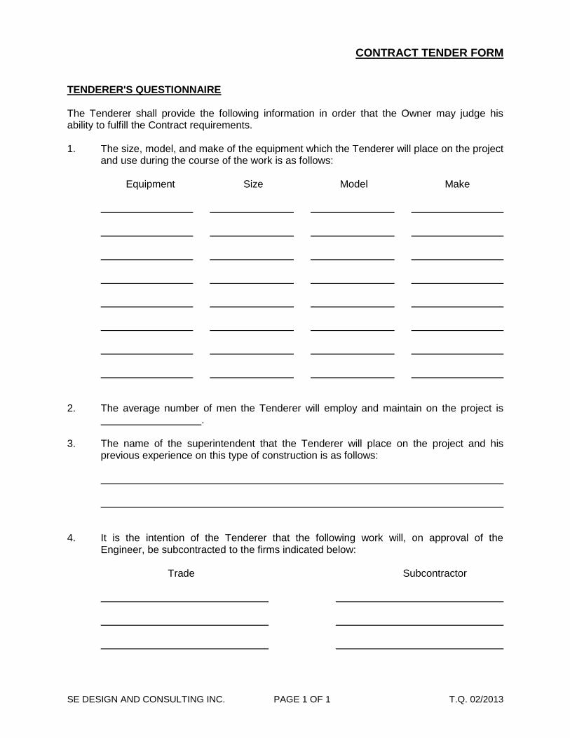
SE DESIGN AND CONSULTING INC. PAGE 1 OF 1 T.Q. 02/2013
TENDERER'S QUESTIONNAIRE The Tenderer shall provide the following information in order that the Owner may judge his ability to fulfill the Contract requirements. 1. The size, model, and make of the equipment which the Tenderer will place on the project
and use during the course of the work is as follows:
Equipment Size Model Make
2. The average number of men the Tenderer will employ and maintain on the project is
. 3. The name of the superintendent that the Tenderer will place on the project and his
previous experience on this type of construction is as follows:
4. It is the intention of the Tenderer that the following work will, on approval of the
Engineer, be subcontracted to the firms indicated below:
Trade Subcontractor

S E D E S I G N A N D C O N S U L T I N G I N C .
Past Performance The tendering organization’s performance in completing past projects to the quality standards required, time performance, within budget, claims history, project management, and product value will be assessed. Tenderers to include a list of 3 past performance project starting with the most recent project. Tenderers to provide the following information for each project: Project #1 1) Project Name:______________________________________________________________
2) Project Description (Scope) ___________________________________________________
____________________________________________________________________________
____________________________________________________________________________
3) Project Sponsor (Town, City, Province etc):________________________________________
4) Client’s Project Manager (name and phone number):
Name of Project Manager:_________________________________________________
Phone Number:__________________________________________________________
5) Tender Price:_______________________________________________________________
6) Final cost:__________________________________________________________________ 7) If Final cost Higher than Tender price, explain:
____________________________________________________________________________
____________________________________________________________________________
8) Contract Completion date:_____________________________________________________ 9) Actual Completion date:_______________________________________________________ 10) If Actual Completion date after Contract Completion date, explain:
____________________________________________________________________________
____________________________________________________________________________
____________________________________________________________________________

Past Performance
Project #2 1) Project Name:______________________________________________________________
2) Project Description (Scope) ___________________________________________________
____________________________________________________________________________
____________________________________________________________________________
3) Project Sponsor (Town, City, Province etc):________________________________________
4) Client’s Project Manager (name and phone number):
Name of Project Manager:_________________________________________________
Phone Number:__________________________________________________________
5) Tender Price:_______________________________________________________________
6) Final cost:__________________________________________________________________ 7) If Final cost Higher than Tender price, explain:
____________________________________________________________________________
____________________________________________________________________________
8) Contract Completion date:_____________________________________________________ 9) Actual Completion date:_______________________________________________________ 10) If Actual Completion date after Contract Completion date, explain:
____________________________________________________________________________
____________________________________________________________________________
____________________________________________________________________________

Past Performance
Project #3 1) Project Name:______________________________________________________________
2) Project Description (Scope) ___________________________________________________
____________________________________________________________________________
____________________________________________________________________________
3) Project Sponsor (Town, City, Province etc):________________________________________
4) Client’s Project Manager (name and phone number):
Name of Project Manager:_________________________________________________
Phone Number:__________________________________________________________
5) Tender Price:_______________________________________________________________
6) Final cost:__________________________________________________________________ 7) If Final cost Higher than Tender price, explain:
____________________________________________________________________________
____________________________________________________________________________
8) Contract Completion date:_____________________________________________________ 9) Actual Completion date:_______________________________________________________ 10) If Actual Completion date after Contract Completion date, explain:
____________________________________________________________________________
____________________________________________________________________________
____________________________________________________________________________

Safety Record
Do you have your Certificate of Recognition? Yes No, Attach a Copy. Do you have your WCB Clearance? Yes No Do you have any Fatalities? Yes No, If yes how many? _________________________ Have you had any loss incidents in the last 3 years? Yes No, If so, please explain
____________________________________________________________________________
____________________________________________________________________________
____________________________________________________________________________
____________________________________________________________________________
____________________________________________________________________________
____________________________________________________________________________
____________________________________________________________________________
Provide the following information:
Year Loss Time Incidents
Medical Aids Modified/Restricted Duty Incidents
Total Hours Worked
2016
2015
2014
Indicate total number of persons employed:____________________________
Attach a copy of your WCB Premium Statement with your tender form.

S E D E S I G N A N D C O N S U L T I N G I N C .
Relevant Experience Previous experience of the tenderers will be assessed in relation to the fields of expertise required to achieve the intended outcomes of the project. Recent experience is more valuable than historic experience. The company’s experience in technical areas comparable to the tendered project, the scale of past projects and the role undertaken within those projects will be considered. Tenderers to include a list of 3 relevant project starting with the most recent project. Tenderers to provide the following information for each project: Project #1 Project Name : ________________________________________________________________
Project Description (Project Scope):
____________________________________________________________________________
____________________________________________________________________________
____________________________________________________________________________
Relevance to the tendered Project:
____________________________________________________________________________
____________________________________________________________________________
____________________________________________________________________________
Role of the Tenderer (Prime, sub-contractor, other). If sub-contractor, indicate percentage of the
work of the overall project you did as a sub-contractor______%:
____________________________________________________________________________
____________________________________________________________________________
____________________________________________________________________________
Indicate total Project Cost: ______________ If Sub-Contractor Indicate your Project Cost:________________ Duration of Project:_____________________________________________________________

Relevant Experience
Project #2 Project Name: _______________________________________________________________
Project Description (Project Scope):
____________________________________________________________________________
____________________________________________________________________________
____________________________________________________________________________
Relevance to the tendered Project:
____________________________________________________________________________
____________________________________________________________________________
____________________________________________________________________________
Role of the Tenderer (Prime, sub-contractor, other). If sub-contractor, indicate percentage of the
work of the overall project you did as a sub-contractor______%:
____________________________________________________________________________
____________________________________________________________________________
____________________________________________________________________________
Indicate total Project Cost: ______________ If Sub-Contractor Indicate your Project Cost:________________ Duration of Project:_____________________________________________________________

Relevant Experience
Project #3 Project Name: _______________________________________________________________
Project Description (Project Scope):
____________________________________________________________________________
____________________________________________________________________________
____________________________________________________________________________
Relevance to the tendered Project:
____________________________________________________________________________
____________________________________________________________________________
____________________________________________________________________________
Role of the Tenderer (Prime, sub-contractor, other). If sub-contractor, indicate percentage of the
work of the overall project you did as a sub-contractor______%:
____________________________________________________________________________
____________________________________________________________________________
____________________________________________________________________________
Indicate total Project Cost: ______________ If Sub-Contractor Indicate your Project Cost:________________ Duration of Project:_____________________________________________________________

GENERAL CONDITIONS
SE DESIGN AND CONSULTING INC. -i-
TABLE OF CONTENTS
ART. DESCRIPTION PAGE NO. ART. DESCRIPTION PAGE NO.
1 Definition of Terms 1 25 Rejected Work or Materials 16 2 Intent of Contract Documents 3 26 Correction of Deficiencies 17 3 Drawing and Specifications 3 27 Guarantee Period 17 4 Document Conflict 3 28 Guarantee Fund 18 5 Discrepancies 4 29 Insurance 19 6 Shop Drawings 4 30 Damage to Work 23 7 Reference Points and Layout 6 31 Indemnity 23 8 Engineer’s Status 7 32 Bonds 23 9 Arbitration 8 33 Patents and Royalties 24 10 Inspection of Work 8 34 Permits and Regulations 24 11 Supervision and Labour 9 35 Injury or Damage 24 12 Lands by Owner 10 36 Notice to Proceed 25 13 Lands by Contractor 10 37 Failure to Complete on Time 25 14 Private Land 10 38 Schedule of Completion 25 15 Owner’s Right to do Work 11 39 Changes in the Work 26 16 Owner’s Termination of Contract 11 40 Unclassified Work 26 17 Contractor’s Termination of Contract 13 41 Extension of Contract Time 27 18 Assignment of Contract 13 42 Use of Competed Portions 28 19 Separate Contract 14 43 Payments 29 20 Sub-Contract 14 44 Removal of Liens 31 21 Oral Agreement 15 45 Completion and Acceptance 31 22 Materials by Contractor 15 46 Traffic 32 23 Materials by Owner 15 47 Variation of Information 32 24 Materials Storage 16 48 Existing Services 33 49 Prime Contractor 33
50. Engineer Safety Program 35

GENERAL CONDITIONS
SE DESIGN AND CONSULTING INC. -1-
1. DEFINITION OF TERMS
.1 "OWNER" is the Owner named in the Contract Agreement. .2 "CONTRACTOR" is the Contractor named in the Contract
Agreement. .3 "ENGINEER" is SE DESIGN AND CONSULTING INC., or
such other Engineer as may from time to time be duly authorized and appointed in writing by the Owner.
.4 "SUBCONTRACTOR" shall mean any person, firm, or
corporation having a contract for the execution of a part or parts of the work included in this Contract, and a person, firm, or corporation furnishing material called for in this Contract and worked to a special design according to the drawings or specifications but does not include one who merely furnishes material not so worked.
.5 "OTHER CONTRACTOR" wherever used in these
documents means any person or firm or corporation employed by or having a Contract directly or indirectly with the Owner other than through the Contractor.
.6 "CONTRACT" shall be the executed Contract Agreement
between the Owner and the Contractor. .7 "CONTRACT DOCUMENTS" shall mean and include the
complete set of documents, specifications, drawings, and addenda incorporated therein, as listed in the Index of Contract Documents.
.8 "CONTRACT PRICE" shall mean the amount of the Contract
as shown in the Contract Tender Form. .9 "WORK" wherever used in these documents shall mean the
entire Work, including materials, labour, equipment, transportation or other facilities or items ancillary to the foregoing, required to be done, furnished and performed by the Contractor to complete the Contract in accordance with the Contract Documents.
.10 "UNCLASSIFIED WORK" shall mean work not covered in
unit prices or lump sum amounts in the Tender Form. .11 "GUARANTEE PERIOD" shall be a specified period of time
beginning on the date stated in the "Notice of Acceptance". .12 "GUARANTEE FUND" is an amount held by the Owner
during the Guarantee Period to ensure correction of deficiencies.

GENERAL CONDITIONS
SE DESIGN AND CONSULTING INC. -2-
.13 "CERTIFICATES"
.1 Monthly Progress Certificate shall mean a certificate issued
by the Engineer periodically, based on which payments on account are made.
.2 Interim Completion Certificate shall mean a certificate
issued by the Engineer upon substantial completion of the Work.
.3 Final Completion Certificates shall mean a certificate issued
by the Engineer upon completion of the Work including cleanup and rectification of all deficiencies.
.4 Release of Holdback Certificate shall mean a certificate
issued by the Engineer upon expiration of the 45 day Statutory Limitation period authorizing the payment of Holdback.
.5 Final Acceptance Certificate shall mean a certificate issued
by the Engineer within 14 days after the end of the period of guarantee provided that the Conditions of the Contract have been met.
.14 '"FIELD ORDER" is a written communication from the
Engineer, at the site, to the Contractor, ordering changes in the Work, clarifying the Contract Documents, issuing instructions or requesting information.
.15 "NOTICE OF PROPOSED CHANGE" is a written
communication issued from the Office of the Engineer during the course of the Work informing of the changes to be made in the Work.
.16 "CHANGE ORDER" is a written communication issued by
the Owner, setting forth the authorized amount by which the Contract Price is to be altered as a result of changes in the Work ordered by a Notice of Proposed Change.
.17 "NOTICE OF ACCEPTANCE" is a written communication
issued by the Owner, acknowledging the interim or final completion and setting the commencement of Guarantee Periods.

GENERAL CONDITIONS
SE DESIGN AND CONSULTING INC. -3-
2. INTENT OF CONTRACT DOCUMENTS
.1 The intent of the Contract Documents is that the Contractor shall
provide all necessary materials, supervision, labour, equipment, and all else necessary for the proper execution of the Work unless specifically noted otherwise.
.2 The Contractor shall do all the Work shown on the drawings and
described in the specifications and all incidental Work necessary to complete the project.
3. DRAWINGS AND SPECIFICATIONS
.1 Except as provided for otherwise, a maximum of one (1) copy of
drawings and specifications for the execution of the Work shall be furnished to the Contractor without charge.
.2 Additional instructions may be issued by the Engineer during the
progress of the Work by means of drawings or otherwise for clarification of the drawings and specifications, or as may be necessary to explain or illustrate changes in the Work to be done.
.3 One (1) complete set of all drawings and specifications shall be
maintained at the job site and shall be available to the Engineer at all times.
4. DOCUMENT CONFLICT
.1 In case of any inconsistency or conflict between the provisions of
the Contract Documents, the provisions of such documents and addenda thereto shall take precedence and govern in the following order:
.1 Contract Agreement .2 Special Provisions .3 General Conditions .4 Specifications .5 Drawings .6 Tender Form

GENERAL CONDITIONS
SE DESIGN AND CONSULTING INC. -4-
.7 Instructions to Tenderers .8 Invitation to Tender .9 All other Documents
.2 Figured dimensions on a drawing take precedence over
measurements scaled from the drawing, and large-scale drawings take precedence over those of smaller scale.
.3 Supplementary drawings and specifications supersede their
antecedents. .4 In case of conflict between figured dimensions on a drawing and
the dimensions of a specified product, the dimensions of the specified product shall govern.
.5 In case of conflict in materials and methods, the specifications
govern. .6 The drawings and specifications complement each other and
anything called for by one shall be as binding as if called for by both.
.7 The apparent generality of the drawings and specifications as to
any detail or the apparent omission from them of a detailed description concerning any point, shall be regarded as meaning that only the best general practice is to prevail and that only material and workmanship of the first quality are to be used.
5. DISCREPANCIES
.1 Any discrepancies found between the drawings and specifications
or any errors or omissions in the drawings or specifications shall immediately be reported to the Engineer, who shall promptly correct such error or omission in writing.
.2 Any Work done after discovery of such discrepancies, errors, or
omissions shall be done at the Contractor's risk.
6. SHOP DRAWINGS
.1 The Contractor shall arrange for the preparation of a minimum of 2
sets of clearly identified shop drawings, 1 of which will be retained by the Engineer.
.2 The Contractor shall ensure that the drawings conform to the
following standards:

GENERAL CONDITIONS
SE DESIGN AND CONSULTING INC. -5-
.1 All drawings are to be metric. .2 All dimensions are to be in metres or millimetres. .3 Drawings are to be done to one of the following scales: 1:20 - Small Intricate Details 1:50 - General Details 1:500 - Overall Layout and Large Plans 1:1000- Key Plans .4 Sheet sizes are to be one of the following: 216 X 280 280 X 432 432 X 559 559 X 864 864 X 1118
.5 Imperial catalogue sheets will be accepted if the dimensions given are converted to metric.
.3 Prior to submission to the Engineer the Contractor shall review all
shop drawings. .4 By this review the Contractor represents that he has determined
and verified all field measurements, field construction criteria, materials, catalogue numbers and similar data or will do so and that he has checked and coordinated each shop drawing with the requirements of the Work and of the Contract Documents.
.5 The Contractor's review of each shop drawing shall be indicated by
stamp, date and signature of a responsible person. .6 The Contractor shall submit shop drawings to the Engineer for his
review with reasonable promptness and in orderly sequence so as to cause no delay in the Work or in the Work of Other Contractors.
.7 If either the Contractor or the Engineer so requests they shall jointly
prepare a schedule fixing the dates for submission and return of shop drawings.
.8 Shop drawings shall be submitted in the form of a reproducible
transparency or prints as the Engineer may direct. .9 At the time of submission the Contractor shall notify the Engineer in
writing of any deviations in the shop drawings from the requirements of the Contract Documents.
.10 The Engineer will review and return shop drawings in accordance
with any schedule agreed upon, or otherwise with reasonable

GENERAL CONDITIONS
SE DESIGN AND CONSULTING INC. -6-
promptness and in no case will the period between receipt of shop drawings and return of the submissions exceed 14 days.
.11 The Engineer's review shall be for conformity to the design concept
and for general arrangement only and such review shall not relieve the Contractor of responsibility for errors or omissions in the shop drawings or of responsibility for meeting all requirements of the Contract Documents unless a specific deviation on the shop drawings has been approved in writing by the Engineer.
.12 The Contractor shall make any changes in shop drawings which
the Engineer may require consistent with the Contract Documents and re-submit unless otherwise directed by the Engineer.
.13 When re-submitting, the Contractor shall notify the Engineer in
writing of any revisions other than those requested by the Engineer.
7. REFERENCE POINTS AND LAYOUT
.1 The Engineer shall establish base lines and reference points, for
the location of principal components of the Work, as well as bench marks in reasonable proximity to the Work.
.2 The Contractor shall carefully preserve bench marks, reference
points and stakes, and legal survey pins, and in case of willful or careless destruction, the Contractor will be charged with the resulting expense and shall be responsible for any mistakes that may be caused by their loss or disturbance.
.3 The Contractor shall provide all detailed layout of dimensions,
locations, and elevations of the Work from the base lines, reference points, and bench marks set by the Engineer.
.4 The Contractor shall not proceed with the Work until he has made
timely demands upon the Engineer for, and has received from the Engineer, such base lines, reference points, elevations and other points and instructions required for the execution of the Work.
.5 In some cases, if so specified in the Special Provisions, the
Engineer will provide detailed layout of the Work. When it is the Engineer's responsibility to lay out the Work, the Contractor shall provide reasonable and necessary opportunity and facilities for setting points and making measurements. The Work shall be done in strict conformity with such points and instructions.
.6 Unless otherwise specified in the Special Conditions, the
Contractor shall furnish all assistants necessary to measure in and drive stakes and shall furnish such lines, straight edges and stakes

GENERAL CONDITIONS
SE DESIGN AND CONSULTING INC. -7-
as the Engineer may direct for setting line and grade, and other detailed layout.
.7 The Contractor, shall, before commencing Work at any point,
satisfy himself as to the meaning and correctness of all stakes and Works and no claims shall be considered for any allowance based on alleged inaccuracies or for alternatives on account of his failure to read same correctly.
.8 If the Contractor, in the course of the Work, finds any discrepancy
between the drawings and the physical conditions of the locality or any errors or omissions in drawings or in the layout as given by points and instruction, it shall be his duty to immediately inform the Engineer in writing, and the Engineer shall promptly verify the same and issue appropriate instructions. Any Work done after such discovery, before further Work is authorized, will be done at the Contractor's risk.
8. ENGINEER'S STATUS
.1 The Engineer shall be the Owner's representative during the construction
period and shall observe the Work in progress on behalf of the Owner. .2 He shall have the authority to stop the Work whenever such stoppage
may be necessary, in his reasonable opinion, to ensure the proper execution of the Contract.
.3 The Engineer is, in the first instance, the sole interpreter of the Contract
and the sole judge of the performance thereunder by both parties to the Contract.
.4 The Contract shall obey, perform, and comply with the Engineer's orders
or instructions with respect to the Work, or concerning the conduct thereof, promptly, efficiently, and to the satisfaction of the Engineer.
.5 The contractor shall not enter into any contractual discussion and or
contractual changes with the owner without the presence of the engineer. .6 However, should the Contractor hold such orders or instructions to be at
variance with the Contract Documents or to involve changes in Work already done, ordered, or underway in excess of the Contract, he shall notify the Engineer accordingly in writing within ten (10) days of the receipt of such orders or instructions and before proceeding to carry them out.
.7 Nothing contained in the Contract Documents shall create any contractual
relationship between the Engineer and the Contractor.

GENERAL CONDITIONS
SE DESIGN AND CONSULTING INC. -8-
9. ARBITRATION
.1 The Engineer shall, in the first instance, be the sole interpreter of the
Contract in the event of any dispute or misunderstanding between the Owner and the Contractor in relation to the stipulation and provisions of this Contract, or to the manner and performance of the whole or any part of the Contract by either of the parties.
.2 Should either party not agree with the decisions of the Engineer in any
such dispute, the matter shall be submitted to arbitration as provided for by the "Arbitration Act" of the Province or Territory wherein the Work is situated, and amendments thereto.
.3 No action at law shall be commenced by either the Contractor or the
Owner until the arbitration proceedings have been completed. .4 The Contractor shall not cause a delay of the Work while the arbitration
proceedings are pending or in progress. .5 Parties must expressly agree to arbitrate in writing. If one or both party do
not want to proceed with the Arbitration process, the dispute may be brought forward to the Judicial system.
10. INSPECTION OF WORK
.1 The Contractor shall allow the Engineer and/or Owner access and provide
adequate facilities for access to any part of the Works at all times. .2 If the specifications, Engineer's instruction, laws, ordinances, or any public
authority requires any Work to be specially tested or approved, the Contractor shall give the Engineer advance notice of his preparedness for such inspection, and if the inspection is by an authority other than the Engineer, of the date fixed for such inspection.
.3 The Engineer shall inspect the Work promptly and without causing
unreasonable delay to the Contractor. .4 Extra payment will not be made to the Contractor for delay occasioned by
any inspection, and extension of the completion time will not be allowed for delay resulting therefrom.
.5 On request by the Engineer, the Contractor shall open for inspection any
part of the Work that has been covered up. If the Contractor refuses to comply with such request, the Owner may employ other persons to uncover the Work.

GENERAL CONDITIONS
SE DESIGN AND CONSULTING INC. -9-
.6 If the Work is found to be in accordance with the Contract requirements then the cost of uncovering and recovering the Work shall be borne by the Owner.
.7 If any of the Work was covered by the Contractor in contravention of the
Engineer's instruction, or if the uncovered Work is found not to be in accordance with the Contract requirements, then the cost of uncovering the Work shall be charged to the Contractor.
.8 The acceptance, or the lack of comment on the part of the Engineer, of
the methods, techniques or sequence of construction employed by the Contractor shall not relieve the Contractor of his responsibility for the Work.
.9 At anytime during the warranty period the underground piping (Storm &
sanitary) system experiences failure, blockages etc. Under the direction of the Engineer the contractor will have to CCTV the pipes to determine the reason for failure and then carry-out the necessary repairs under the supervision of the Engineer. Once the repairs is completed, the contractor will have to CCTV the pipe to confirm the repairs is satisfactory. Contractor to pay for the CCTV and the repairs.
11. SUPERVISION AND LABOUR
.1 The Contractor shall keep on the Work at all times during its progress a
competent superintendent who is acceptable to the Engineer. .2 The superintendent shall represent the Contractor in his absence and
directions given to him shall be held to be given to the Contractor. .3 The superintendent shall give sufficient supervision to the Work until its
completion. .4 The Contractor shall comply with the requirements of the Worker's
Compensation Act of the Province or Territory in which the Work is carried out, and all other federal and provincial legislation regarding wages and labour regulations.
.5 All workmen must have sufficient knowledge, skill and experience to
perform properly the Work assigned to them. .6 Any foreman or workman employed by the Contractor or Subcontractor
who, in the opinion of the Engineer, does not perform his Work in a skillful manner, or appears to be incompetent or to act in a disorderly or intemperate manner shall, at the written request of the Engineer, be discharged immediately and shall not be employed again in any portion of the Work without the approval of the Engineer.

GENERAL CONDITIONS
SE DESIGN AND CONSULTING INC. -10-
12. LANDS BY OWNER
.1 The Owner shall provide the lands upon which the Work is to be
performed. Where Work is to be performed on lands owned by others, the Owner shall obtain the necessary easements or rights-of-way.
.2 Delay in providing these lands, or obtaining easements or rights-of-way
which, in the opinion of the Engineer, delays the Work or results in extra cost to the Contractor, shall be deemed proper cause for adjustment in the time of completion or adjustment of the Contract Price to cover the extra cost to the Contractor.
13. LANDS BY CONTRACTOR
.1 Any lands other than those upon which the Work is to be performed which
may be required for temporary facilities, storage purposes, or access to the Work site, other than those provided by the Owner, shall be provided by the Contractor with no liability to the Owner.
14. PRIVATE LAND
.1 It shall be the Contractor's responsibility to ascertain the boundaries within
which the Work must be confined. The Contractor shall not enter upon lands other than those provided by the Owner for any purpose without obtaining prior written permission of the property Owner.
.2 The Contractor shall not enter upon lands owned by others on which the
Owner has easements or right-of-entry without having received the written authorization of the Owner for such entry.
.3 It shall be the Contractor's responsibility to ascertain from the Owner the
conditions on which easements or rights-of-entry have been granted on private lands and to abide by these condition throughout the course of construction.
.4 Contractor is to be notified that if he/she makes a contractual arrangement
with the client without the presence of the Engineer who is the contractual authority, the contractor may not be financially compensated for his/her effort.
.5 If the Contractor requires access to private land to conduct his/her activity,
(for example using land as laydown area, or spill pile dirt from excavation),

GENERAL CONDITIONS
SE DESIGN AND CONSULTING INC. -11-
contractor is to make sure the terms are made clear in writing and signed by the land owner and the contractor. Terms of the agreement must indicate what is agreed upon between both parties and restauration that is required after work is completed. A copy of this agreement must be provided to the Engineer. Contractor to note that the Owner will be absolved of any responsibility towards potential claim that may occur between the land owner and the contractor.
15. OWNER'S RIGHT TO DO WORK
.1 The Owner, subject to the approval of the Engineer, may notify the
Contractor and his surety, in writing, that the Contractor is in default of his contractual obligations and instruct him to correct the default within five (5) working days, if the Contractor should:
.1 Refuse or fail to supply sufficient properly skilled
workmanship, products, or construction machinery and equipment for the scheduled performance of the Work.
.2 Neglect to prosecute the Work properly, or fail to perform
any of the provisions of the Contract.
.2 If the correction of the default cannot be completed within the five (5) working days specified, the Contractor shall be considered to be in compliance with the Owner's instruction if he:
.1 Commences the correction of the default within the
specified time. .2 Provides the Owner with an acceptable schedule for such
correction. .3 Completes the correction in accordance with such
schedule. .3 If the Contractor fails to comply with these provisions, the Owner may,
without prejudice to any other right or remedy he may have, correct such default and may deduct the cost thereof from the payment then or thereafter due the Contractor, provided however, that the Engineer shall approve both the action and the amount subsequently charged to the Contractor.
16. OWNER'S TERMINATION OF THE CONTRACT
.1 The Owner shall have the right to terminate the Contractor for any of the
following reasons:

GENERAL CONDITIONS
SE DESIGN AND CONSULTING INC. -12-
.1 If the Contractor at any time becomes bankrupt, makes an assignment of his property for the benefit of his creditors, or if a receiver should be appointed. Such termination shall be effective upon the Owner giving notice thereof.
.2 If the Contractor should default in any of the following ways
and fail to remedy such default within the ten (10) days of notice to do so. Such termination shall be effective upon the Owner giving notice thereof:
.1 Fail to commence Work within the time specified in
the Contract Agreement. .2 Fail to use diligence or to make such progress with
the Work as, in the opinion of the Engineer, is necessary to ensure the completion of the Work in the time specified in the Contract Agreement.
.3 Fail, in the opinion of the Engineer, to supply enough
competent workmen, management, and suitable equipment.
.4 Become, in any way, in the opinion of the Engineer,
unable to carry on the construction of the Works.
.2 Upon termination of the Contract, the Owner may take all the Work out of the Contractor's hands and employ such means as he may see fit to complete the Works.
.3 Upon termination of the Contract, the Contractor shall have no claim for
any further payment in respect of Work performed, but shall be liable for all loss of profits, damages, and expenses which may be suffered by the Owner by reason of such default or delay, or the non-completion by the Contractor of the Works.
.4 Upon termination of the Contract, no objection or claim shall be raised or
made by the Contractor by reason or on account of the ultimate cost of the Works so taken over for any reason proving greater than, in the opinion of the Contractor, it should have been.
.5 Upon termination of the Contract, all materials, articles and things
whatsoever, and all equipment and all rights, proprietary or otherwise, licenses, powers and privileges, whether relating to or affecting real estate or personal property, acquired, possessed, or provided by the Contractor for the purposes of the Work under the provisions of this Contract shall remain and be the property of the Owner for all purposes incidental to the completion of the Works and may be used, exercised, and enjoyed by the Owner as fully to all intents and purposes connected with the Works as

GENERAL CONDITIONS
SE DESIGN AND CONSULTING INC. -13-
they might therefore have been used, exercised, and enjoyed by the Contractor.
17. CONTRACTOR'S TERMINATION OF THE CONTRACT
.1 The Contractor shall have the right to terminate the Contract for any of the
following reasons:
.1 In the event of an Order of any court or other public authority, other than the Owner, causing the Work to be stopped or suspended, and when the period of such stoppage or suspension exceeds ninety (90) days, and when such stoppage or suspension occurs through no act or fault of the Contractor, his agents, or servants. In such event, the Contractor shall receive from the Owner payment for the Work performed and losses sustained in respect of materials. The Owner shall not be liable for any loss of profits, damages or expenses incurred by the Contractor as a result of such stoppage or suspension. Such termination shall be effective upon the Contractor giving notice thereof.
.2 In the event the Owner fails to pay, except as provided in
Article 43 of the General Conditions, any sum certified by the Engineer within twenty (20) days from the specified date of payment, and fails to remedy such default within ten (10) days of the Contractor's written notice to do so. In such event, the Contractor shall receive from the Owner payment for the Work performed and losses sustained in respect of any materials and payment for loss of profits, damages, and expenses. Such termination shall be effective upon the Contractor giving notice thereof.
18. ASSIGNMENT OF CONTRACT
.1 The Contractor shall not assign the Contract or any part thereof or any
benefit or interest therein or thereunder without the prior written consent of the Owner.
.2 This shall not exclude a charge in favour of the Contractor's bankers of
any monies due or to become due under this Contract. .3 Such assignment shall be promptly notified in writing to the Owner.

GENERAL CONDITIONS
SE DESIGN AND CONSULTING INC. -14-
19. SEPARATE CONTRACTS
.1 The Owner reserves the right to let other contracts in connection with the Work.
.2 The Contractor shall afford Other Contractors reasonable opportunity for
the introduction and storage of their materials and the execution of their Work and shall properly connect and co-ordinate his Work with theirs.
.3 If any of the Contractor's Work as specified herein and shown on the
drawings depends upon the Work of any Other Contractor, the Contractor shall inspect and measure the Work in place and determine whether anything in such Work renders it unsuitable for proper execution of his Work.
.4 He shall promptly report the results of such inspection and measurement
to the Engineer if anything in such Work renders it unsuitable for proper execution of his Work.
.5 His failure to inspect and report promptly shall constitute an acceptance of
the Other Contractor's Work and he shall have no claim against the Owner by reason of anything in such Work rendering the same unsuitable for proper execution of his Work.
20. SUBCONTRACTS
.1 The Subcontractors named in the Tenderer's Questionnaire, and others
as may be approved by the Engineer following execution of the Contract Agreement shall not be changed nor shall additional Subcontractors be employed except with the written approval of the Engineer.
.2 The Contractor is responsible to the Owner for the acts and omissions of
his Subcontractors and of their employees, to the same extent that he is responsible for the acts or omissions of persons employed by himself.
.3 Nothing in the Contract Documents shall create any contractual relation
between any Subcontractor and the Owner. .4 The Contractor shall bind every Subcontractor by the terms of the
Contract Documents.

GENERAL CONDITIONS
SE DESIGN AND CONSULTING INC. -15-
21. ORAL AGREEMENTS
.1 No oral instruction, objection, claim or notice by any party to the others
shall affect or modify any of the terms or obligations contained in any of the Contract Documents.
.2 None of the provisions of the Contract Documents shall be held to be
waived or modified by reason of any act whatsoever, other than by an agreed waiver or modification thereof in writing.
.3 Under no circumstances is the contractor allowed to enter into a separate
contract with other parties that may impact the signed contract with the owner. If contractor requires permission from the land owner to use as a laydown area or any other general purpose during construction, contractor is to get the permission in writing from the owner and provide a copy to the Engineer.
22. MATERIALS BY CONTRACTOR
.1 The Contractor shall supply materials to construct the Work unless it is
expressly stipulated to the contrary. .2 Materials used in the Work shall meet the requirements of the
specifications, or where not detailed in the specifications, shall be to the Engineer's satisfaction.
.3 Unless otherwise specified, all materials shall be new. .4 Unless otherwise stipulated, the Contractor shall provide all water, light
and power necessary for the execution of the Work. .5 Schedules of piping, fittings, reinforcing, or other materials indicating
quantity and/or dimension, which are shown on the drawings or in the applicable sections of the specifications, are intended only to assist the Contractor in his quantity takeoff. Quantities and dimensions shown therein are not guaranteed to be accurate and shall be checked by the Contractor prior to placing an order for such materials.
23. MATERIALS BY OWNER
.1 The Owner will provide only such materials as are specifically listed as
being supplied by the Owner. .2 Materials supplied by the Owner already on the site or other designated
location at the time of Contract execution, and materials delivered

GENERAL CONDITIONS
SE DESIGN AND CONSULTING INC. -16-
following execution of the Contract, shall be examined by the Contractor for quantity and defects, and the Contractor shall sign a statement of materials acceptance specifically listing materials and quantities thereof, and noting all defective material. In so accepting these materials, the Contractor shall assume responsibility for their protection and, except for latent defects not reasonably noticeable at the time of examination, for their quality.
.3 Unless otherwise specified, the Contractor shall take delivery of materials
supplied by the Owner at the point of delivery nearest to the Works and shall, at his own cost, pay all demurrage, insurance, standby charges, wharfage, and other unloading costs, and costs of transporting such materials from the point of delivery to the job site.
.4 The Contractor shall verify the delivery dates of materials provided by the
Owner and shall arrange Work schedules to comply therewith.
24. MATERIALS STORAGE
.1 The Contractor, at his own cost, shall store all materials provided for the
Work either by himself or the Owner until they have been incorporated into the completed Works.
.2 Materials shall be so stored as to ensure the preservation of their quality
and fitness for the Work, and shall be protected from vandalism and theft. .3 Stored materials shall be located so as to facilitate prompt inspection. .4 Faulty materials shall not be stored on the site.
25. REJECTED WORK OR MATERIALS
.1 All materials which do not conform to the requirements of the Contract
Documents, or not approved by the Engineer, or are in any way unsatisfactory or unsuited to the purpose for which they are intended, will be rejected.
.2 Any defective Work, which shall include materials, whatever the cause
thereof, and without limiting the generality of the foregoing, whether the result of poor workmanship or use of defective materials shall be removed within ten (10) days after written notice is given by the Engineer, and the Work shall be re-executed by the Contractor.
.3 The fact that the Engineer may have previously overlooked such defective
Work shall not constitute an acceptance.

GENERAL CONDITIONS
SE DESIGN AND CONSULTING INC. -17-
.4 The removal of Work and the re-execution thereof shall be at the expense of the Contractor, and he shall pay the cost of replacing the Work which shall include materials of Other Contractors destroyed or damaged by the removal of the rejected Work or materials and the subsequent replacement with acceptable Work.
.5 If, in the opinion of the Engineer, it is not expedient to re-execute
defective Work, the Owner may deduct from the Contract price the difference in value between the Work as done and the Work called for by the Contract, the amount of which shall be determined by the Engineer.
26. CORRECTION OF DEFICIENCIES
.1 Upon failure of the Contractor to perform the Work in accordance with the
Contract Documents, and after ten (10) days written notice to the Contractor, or without notice if an emergency or danger to the Work or public exists, the Owner may, without prejudice to any other remedy he may have, correct such deficiencies.
.2 The cost of Work performed by the Owner in correcting deficiencies shall
be paid by the Contractor.
27. GUARANTEE PERIOD
.1 Neither the final progress payment nor the Notice of Acceptance shall relieve the Contractor of responsibility for faulty materials or defective workmanship.
.2 The Contractor, unless specifically stated otherwise herein, guarantees all
materials furnished and Work performed by him during construction and warranty period. The guarantee period includes the construction period (from the Notice of Acceptance to Construction Completion Certificate) and two (2) years warranty period following the Construction Completion Certificate until Final Acceptance Certificate (FAC).
.3 Faulty materials shall be replaced and defects discovered and failures
which occur during the two (2) years Guarantee Period shall be rectified to the satisfaction of the Engineer and in accordance with the Contract Documents, including, if deemed necessary by the Engineer, replacement of all or a portion of the Work.
.4 If the Owner observes through use of the Works, or if it is discovered by
tests or inspection of the Works prior to the end of the Guarantee Period, that a deficiency or defect exists in the materials or workmanship in respect to the specified Works, the Owner shall immediately notify the

GENERAL CONDITIONS
SE DESIGN AND CONSULTING INC. -18-
Contractor, by whatever means are available, of the defect or deficiency and instruct him to rectify the fault. Such notification shall be confirmed by the Owner in writing to the Contractor.
.5 In the event that this Work, in the opinion of the Owner, must be done
immediately to prevent serious damage, injury, or loss of life, the Owner may perform or cause to be performed, the necessary Work and shall notify the Contractor accordingly.
.6 Work required under guarantee shall, except as otherwise provided herein
for emergencies, be carried out by the Contractor or his representative within ten (10) days of the Owner's written instruction to perform the Work.
.7 In the event that this Work is not done by the Contractor within five (5)
days, the Owner may take whatever action is necessary to have the Work done.
.8 All costs resulting from the necessity to do Work under the guarantee
requirement, whether it be done by the Contractor, his representative, or the Owner, as provided herein, shall be borne by the Contractor.
.9 The Contractor shall, in addition, be liable to the Owner for all expenses,
losses, or damages incurred by the Owner as a result of such faulty materials and defective workmanship or as a result of the Contractor's failure to meet the guarantee requirements as specified herein.
.10 This Article shall not restrict the liability of the Contractor in any way.
28. GUARANTEE FUND
.1 To ensure the correction of all deficiencies or defects occurring during the Guarantee Period, the Owner shall be entitled to retain from the 10% Holdback Payment an amount double to that of the contract price for any outstanding deficiencies or defects as noted by the engineer unless otherwise specified in the Special Provisions hereinafter referred to as the "Guarantee Fund".
.2 The Owner shall retain the Guarantee Fund until at which time the
deficiencies or defects have been corrected to the satisfaction of the owner and engineer.
.3 Should the Contractor fail to correct all deficiencies and defects occurring
in the Work during the Guarantee Period, the Owner shall be entitled to make withdrawals from the Guarantee Fund sufficient to correct all such deficiencies and defects.

GENERAL CONDITIONS
SE DESIGN AND CONSULTING INC. -19-
.4 In the event the Contractor proceeds to correct all deficiencies and defects in the Work, occurring during the Guarantee Period, the Owner shall pay to the Contractor all monies remaining in the Guarantee Fund.
.5 The Owner shall retain an amount (FAC Holdback) of $50,000.00 from the
Contractor until sign off of Final Acceptance Certificate (FAC). This FAC Holdback may be used in the event there are validated deficiencies identified by the Owner and/or the Engineer either as part of the contract and/or damage to the owner property and/or damage to private land owner property during construction when the contractor refuses to do the repair or is not able to respond within the timeframe requested by the Engineer to do the repair and the Owner had to correct those deficiencies.
.4 This FAC Holdback may also be used in the event the contractor made a
verbal or written agreement with private land owner to conduct his/her activity, (for example using land as laydown area, disposal of spill pile dirt from excavation, borrow pit, etc), and the private land owner is not satisfied that the terms of the verbal or written agreement have been met by the Contractor either at CCC or during the guarantee period and the contractor refuses to correct the deficiency or is not able to respond within the timeframe requested by the Engineer and the Owner had to correct those deficiencies.
.5 If there is a deficiency as part of the contract or from a private land owner
that was validated by the Owner and/or the Engineer, the Contractor will be informed of the deficiency in writing and will be given the opportunity to correct the deficiency. The Contractor must provide a written response within ten (10) calendar days if he/she will repair the deficiency within the Engineer requested timeframe. Upon failure of the Contractor to respond to the letter within the allotted timeframe or to perform the Work within the timeframe requested by the Engineer, the Owner may, without prejudice to any other remedy he may have, correct such deficiencies by whatever means they feel necessary.
.6 The cost of the Work performed by the Owner in correcting deficiencies
shall be paid from the FAC Holdback retain above. The full FAC Holdback will be released minus the cost of any repairs that were carried out by the Owner 30 days after FAC sign off.
.7 No interest will be paid on the Guarantee Fund or the FAC Holdback.
29. INSURANCE
.1 The Contractor shall, at his own expense, provide the insurance coverage
as identified in this article.

GENERAL CONDITIONS
SE DESIGN AND CONSULTING INC. -20-
.2 Each policy shall contain a clause stating that "This policy shall not be cancelled or materially changed without the Insurance Company giving at least fifteen (15) days notice by registered mail to the Owner".
.3 Certified copies of these policies shall be filed by the Contractor with the
Owner prior to commencement of the Work. .4 Wherever the word Owner or Engineer is to appear in these policies, the
legal name shall be inserted. .5 The Contractor shall be solely responsible for all deductible amounts
under the Insurance Policies. .6 Builder's Risk Course of Construction Insurance
.1 The Contractor shall at all times during construction and until all conditions of this Contract (except guarantee provisions) have been fully complied with, keep all buildings, structures, Works, equipment (other than Contractor's mobile equipment) and supplies, including materials which will form part of such building, Works, or structure, which is the subject matter of this Contract, insured in the joint name of the Owner, Engineer and the Contractor for an amount not less than the Contract Price against the following perils: "All risks of direct physical loss or damage from any cause whatsoever, including flood and earthquake, and subject to a maximum deductible of three percent (3%) of the Contract Price".
.2 Such insurance shall be with Insurers and on forms
acceptable to the Owner and shall contain the following clause: "It is agreed that the right to subrogation against the Owner and the Engineer or any of their parent, subsidiary, affiliated, or associated companies or corporations is hereby waived."
.3 The following exclusions shall be deemed permissible
(additional or modified exclusions subject to permission of the Owner).
.1 Any loss of use or occupancy however
caused. .2 Penalties for non-completion of or delay
in completion of Contract or non-compliance with Contract conditions.
.3 Cost of making good faulty
workmanship, construction, or design, but

GENERAL CONDITIONS
SE DESIGN AND CONSULTING INC. -21-
this exclusion shall not be deemed to exclude loss or damage arising as a consequence of faulty workmanship, construction or design.
.4 Wear, tear, normal upkeep, and normal
making good, but this exclusion shall not be deemed to exclude loss or damage arising as a consequence of wear, tear, normal upkeep and normal making good.
.5 Loss, damage, or liability occasioned by,
happening through or in consequence of war, invasion, hostilities, acts of foreign enemies, civil war, rebellion, insurrection, military or usurped power or martial law or confiscation by order of any government or public authority.
.6 Any weapon of war employing atomic
fission or radioactive force whether in time of peace or war.
.7 Claims or liability arising directly or
indirectly from nuclear fission, nuclear fusion or radioactive contamination.
.8 Loss or damage caused by frost or
freezing unless resulting from damage occasioned by fire and/or lightning and/or windstorm and/or hail and/or riot attending a strike and/or civil commotion and/or vehicles and/or smoke.
.9 Loss due to disappearance or revealed
by inventory shortage. .10 Mechanical breakdown, but this
exclusion shall not be deemed to exclude loss or damage arising as a consequence of mechanical breakdown.
.11 Infidelity of the Assured's employees. .12 Loss or damage to material and/or
equipment while in the course of ocean marine shipment, but this exclusion shall not apply to shipments by regular coastwise vessels, regular ferry lines or railway car transfer barges.

GENERAL CONDITIONS
SE DESIGN AND CONSULTING INC. -22-
13. Automobiles or Contractor's equipment
of every description.
.7 Liability Insurance
.1 The Contractor shall buy and keep in force until twenty four (24) months after the date of acceptance, Personal Injury and Property Damage Liability Insurance.
.2 Such insurance shall be in the name of the Contractor and
the Owner, and shall include a Cross Liability or Severability of Interests clause.
.3 Such insurance shall be on a form and with an Insurer
acceptable to the Owner. .4 Both Personal Injury and Property Damage sections are to
provide coverage on an "Occurrence Basis". .5 Exclusions pertaining to the following operations are to be
deleted, if such operations are to be performed by the Contractor or anyone on his behalf.
.1 Blasting or use of explosives .2 Pile driving .3 Excavation
. 4 Underpinning, shoring or removal or rebuilding of support
.5 Demolition
.6 Such insurance shall indemnify the Contractor, Owner and
Engineer for claims arising out of all premises, operations, subcontracted operations, elevators (if any), completed operations, products, and for all liability for personal injury or property damage assumed by the Contractor under any contract or agreement (including this Contract).
.7 Such insurance shall be for the following minimum limits:
Personal Injury and Property Damage - $2,000,000.00 Inclusive per occasion.
.8 Automobile Insurance
.1 The Contractor shall buy and keep in force until all
conditions of the Contract have been fully complied with, a

GENERAL CONDITIONS
SE DESIGN AND CONSULTING INC. -23-
Standard Automobile Policy covering all licensed vehicles owned by him, registered in his name, or leased to him.
.2 Such insurance shall include Liability Insurance for
the following minimum limits: Personal Injury and Property Damage - $1,000,000.00 Inclusive per occasion.
.9 Non-Owned Automobile Insurance
.1 The Contractor shall buy and keep in force until all
conditions of the Contract have been fully complied with, a Standard Non-Owned Automobile Policy including Contractual Liability.
.2 Such insurance shall be for the following limits:
Personal Injury and Property Damage - $2,000,000.00 Inclusive per occasion.
.10 Contractor's Equipment Insurance
.1 Notwithstanding anything contained elsewhere
herein, it is understood and agreed that the Owner and/or Engineer shall not be liable for any loss or damage to Contractor's equipment including loss of use thereof.
.2 Each and every policy insuring Contractor's
equipment to be used on this project shall contain the following clause: "It is agreed that the right to subrogation against the Owner and the Engineer or any of their parent, subsidiary, affiliated, or associated companies or corporation is hereby waived".
30. DAMAGE TO WORK
.1 The Contractor shall bear all loss or damage whatsoever which may arise or occur to the Work or any portion thereof until the same are fully and finally completed and delivered to and accepted by the Owner.
.2 If any such damage or loss occurs before such final completion, delivery
and acceptance, the Contractor shall immediately, at his own expense, repair, restore and re-execute the Work.

GENERAL CONDITIONS
SE DESIGN AND CONSULTING INC. -24-
31. INDEMNITY
.1 The Contractor shall indemnify and save harmless the Owner and
Engineer from and against all losses and all claims, demands, payments, suits, actions, recoveries and judgements of every nature and description brought or recovered against him and/or the Owner or Engineer by reason of any act or omission of the said Contractor, his agents, or employees in the execution of the Work.
32. BONDS
.1 To ensure the faithful execution and proper fulfillment of this Contract, the
Contractor shall provide the Owner with the following bonds at the time of his execution of the Contract Agreement:
.1 A Performance Bond in the amount of fifty percent (50%) of the Contract Price covering the faithful performance of the Contract including the corrections after completion provided for in Article 27 hereof, and the payment of all obligations arising under the Contract.
.2 A Labour and Material Payment Bond in the amount of fifty
percent (50 %) of the Contract Price covering the payment of all labour and material used or reasonably required in the performance of the Contract.
.2 These bonds must be issued by a surety company licensed to conduct
business in the province or territory wherein the Work is located and shall be provided on forms acceptable to the Engineer and compatible with the forms contained within the Contract Documents.
33. PATENTS AND ROYALTIES
.1 The Contractor shall pay all royalties and license fees and shall save the
Owner and Engineer harmless from loss on account of suits or claims which may arise by reason of the Work for infringement of patents in force at the time of execution of the Contract Documents.
34. PERMITS AND REGULATIONS
.1 The Contractor shall, at his own expense, procure all permits, certificates
and licenses required by law for the execution of the Work and shall comply with all federal, territorial, provincial and local laws, regulations and ordinances affecting the execution of the Work.

GENERAL CONDITIONS
SE DESIGN AND CONSULTING INC. -25-
35. INJURY OR DAMAGE
.1 The Contractor shall use due care and take all necessary precautions to
ensure the protection of persons and property and shall comply with the provisions of the Worker's Compensation Act of the province or territory in which the Work is carried out.
.2 The Contractor shall be liable for any and all injury or damage which may
occur to persons or to property due to any act, omission, neglect or default of the Contractor, or of his employees, workmen or agents.
.3 The Contractor shall, without further order, provide and maintain at all
times during the progress or suspension of the Work, suitable barricades, fences, signs, signal lights and flagmen as are necessary to ensure the safety of the public and those engaged in the Work.
.4 In an emergency affecting the safety of life, or of the work, or of adjoining
property, the Contractor, without the necessity of authorization from the Engineer, shall act in a reasonable manner to prevent loss or injury.
.5 The Work shall be carried out in a manner that will cause the least
interruption to vehicular and pedestrian traffic. .6 Where Work is to be carried out on highways or properties other than
those of the Owner, the Contractor shall familiarize himself with the requirements of the owner or controllers of these highways or properties which pertain to traffic control and safety or which place limitations on the Work and shall comply with these requirements.
36. NOTICE TO PROCEED
.1 Written notice to proceed with the Work shall be given to the Contractor
by the Owner. .2 The Contractor will commence Work at such time as to complement the
Work schedule in the Tender Form and shall prosecute the Work regularly and uninterruptedly thereafter, unless otherwise directed in writing by the Engineer or Owner, in such a manner as to secure completion of the Work contracted for within the time stated in the Contract Agreement.
.3 Time shall be of the essence in this Contract.

GENERAL CONDITIONS
SE DESIGN AND CONSULTING INC. -26-
37. FAILURE TO COMPLETE ON TIME
.1 Should the Contractor fail to complete the Work under this Contract within the time specified, the Owner shall be entitled to make deductions from payments due to the Contractor to compensate himself for the following:
.1 Loss of revenue during the extra time required to complete
the Contract if the completed project is revenue-producing. This loss shall, where the same is available, be calculated on the basis of the approved schedule of rates, rents, tolls and/or property assessments established by the Owner.
.2 The cost of engineering services incurred during the extra
time required to complete the Contract.
.3 Any expenses or damages which are incurred by the Owner as a result of the Contractor's failure to complete the Work under this Contract within the time specified.
.2 No bonus will be allowed by the Owner for completion of the Works in less
time than specified in the Contract Agreement.
38. SCHEDULE OF COMPLETION
.1 At such times as the Engineer may request, the Contractor shall provide a
complete construction schedule showing proposed dates for completion of the various phases of the Work.
39. CHANGES IN THE WORK
.1 The Owner may, as the need arises, order changes in the Work through
additions, deletions, modifications or variations, without invalidating the Contract.
.2 The value, if any, of such changes shall be taken into account in
ascertaining the final amount of the Contract Price. .3 All such Work shall be executed under the conditions of the Contract. .4 No extra Work shall be carried out and no charge shall be made, unless
pursuant to a Notice of Proposed Change and no payment for extra Work shall be made without a Change Order.
.5 If the Contractor claims that any instruction by drawings, or otherwise,
involves extra costs under this Contract, he shall give the Engineer written

GENERAL CONDITIONS
SE DESIGN AND CONSULTING INC. -27-
notice thereof immediately and he shall then follow the Engineer's instructions regarding doing the Work in question.
.6 No such claim shall be valid unless so made. If the Contractor's claim is
approved it shall be paid as outlined herein. .7 The value of any change in the Work shall be determined in the following
manner for either an increase or decrease in the Work: .1 By unit prices provided for in the Tender Form. .2 By unit prices agreed upon. .3 By estimate and acceptance in a lump sum. .4 By Unclassified Work.
40. UNCLASSIFIED WORK
.1 When there is a change in the Work, not covered by Contract Unit Prices,
the value of such "Unclassified Work" shall be determined either by an agreement in each instance between the Owner and the Contractor, or, on a cost basis in accordance with the following provisions.
.2 The Contractor shall be paid for Work performed by him as follows:
.1 Approved hourly rates for equipment and labour as set forth using Construction Alberta guidelines or approved hourly rate schedule deemed reasonable within industry standard.
.2 Plus, the Contractor's cost of providing room and board for
labour. .3 Plus, the Contractor's cost for materials on site, less trade
discounts, as established by invoices. .4 Plus 10% fee on the sum of items 40.2.1, 40.2.2 and 40.2.3
to cover overhead, use of small tools and profit. Overhead includes superintendents, time keepers and other administrative and supervisory personnel and shall include the cost of their vehicles.
.5 Plus, the rental of equipment for the hours worked, at
locally accepted rates, or at current provincial or territorial rates, for complete equipment units including operator, fuel, grease, maintenance and such costs as are normal to an operating unit.

GENERAL CONDITIONS
SE DESIGN AND CONSULTING INC. -28-
.6 Plus 5% markup on 40.2.5 to the Contractor (but not Sub-Contractors) provided the Contractor does not own the equipment himself.
.7 Plus, valid transportation costs for bringing in and taking out
equipment specifically required for Unclassified Work, but with no markup.
.3 The Contractor shall be paid for Work performed by his direct Sub-
Contractors, the cost for Sub-Contractors, determined as in 40.2.1, 40.2.2, 40.2.3, 40.2.4 and 40.2.5 and plus 10% to cover the Contractor's coordination.
.4 When Unclassified Work is being done on the cost basis, the Contractor
shall submit to the Engineer, daily, an account, in triplicate, for Work done on the preceding day. The account shall include the man hours, equipment hours and materials used. The Engineer shall, each day, check the account and when he is satisfied that it is correct, he shall sign the three copies and return one signed copy to the Contractor.
.5 If, on any day, the Contractor fails to submit an account for Unclassified
Work, the Engineer shall prepare the account and this shall be used as the basis for payment for that portion of the Work and no payment will be made for any account subsequently submitted by the Contractor for that portion of the Work.
41. EXTENSION OF CONTRACT TIME
.1 The time for completion of the Work under the Contract may be extended
in the event of one (1) or more of the following:
.1 Where extra Work as herein provided is added to the Work under this Contract.
.2 Where the Work is delayed on account of conditions which
could not have been foreseen or which were beyond the control of the Contractor, and which were not the result of the fault or negligence of the Contractor, his agent, or employees, provided however, rain, wind, flood or other natural phenomena of normal intensity for the area shall not be construed as cause for an extension of time for completion of the Work.
.3 Where delay occurs in the progress of the Work as a result
of the act or neglect of the Owner or his employees, or by other contractors employed by the Owner.

GENERAL CONDITIONS
SE DESIGN AND CONSULTING INC. -29-
.4 Where delay occurs as a result of an act of a public authority.
.5 Where the Engineer causes delay in the furnishing of
drawings or necessary information. .6 Where, in the opinion of the Engineer, the Contractor is
entitled to an extension of time.
.2 A claim for extension of Contract time shall only be considered when submitted by the Contractor to the Engineer in writing within seven (7) days of the occurrence of the delay on which the claim is based, provided, however, that in the case of a continuing cause of delay only one (1) claim shall be necessary.
.3 Within a reasonable period after the Contractor submits a request for an
extension of time, the Engineer will present his written recommendation to the Owner stating his opinion on whether or not the delay justifies an extension of time; and, if so, the number of days extension due to the Contractor.
.4 The Owner will make the final decision on all requests for extension of
time.
42. USE OF COMPLETED PORTIONS
.1 The Owner shall have the right to take possession of and use any
completed or partially completed portions of the Work, notwithstanding that the time for completing the entire Work or such portions may not have expired; but such taking possession and use shall not be deemed an acceptance of any Work not completed in accordance with the Contract Documents.
.2 If such prior use increases the cost of, or delays the completion of,
uncompleted Work or causes refinishing of completed Work, the Contractor shall be entitled to such extra compensation or extension of time, or both, as the Engineer may determine.
43. PAYMENTS
.1 At the end of each month, during performance of the Work, the Engineer
shall prepare a Monthly Progress Certificate. .2 A holdback of ten (10%) percent of the total value of all Work performed
and materials on site, as shown on the Monthly Progress Claim, shall be retained, along with any other deductions which the Engineer considers

GENERAL CONDITIONS
SE DESIGN AND CONSULTING INC. -30-
warranted or which may be required in accordance with the conditions of this Contract.
.3 The amount of the Monthly Progress Claim shall be certified by the
Engineer and shall be submitted to the Owner within ten (10) days following the end of the month during which the Work was performed. An acceptable invoice must be submitted by the contractor to the engineer. The Owner must receive contractors invoice within sixty (60) days following the end of the month during which the Work was performed or payment will not be made.
.4 Upon certification by the Engineer, the Owner shall, within thirty (30) days
make payment to the Contractor in the amount certified on the Monthly Progress Claim provided that there is no valid reason for withholding payment.
.5 The Owner may withhold payment, of any Monthly Progress Claim, or the
Final Monthly Progress Claim as may be necessary or prudent to protect himself from loss on account of:
.1 The Contractor not making satisfactory progress. .2 Defective Work which is not remedied. .3 Claims filed, or reasonable expectation that claims will be
filed against the Owner or the Contractor. .4 The failure of the Contractor to make payments properly to
Subcontractors or for materials, labour or otherwise. .5 Damages caused by the Contractor to another Contractor. .6 Any other evidence of loss or danger of loss by the Owner,
on account of the Contractor's operations.
.6 When the grounds identified in 43.5 are removed, payment shall be made of accounts withheld because of them.
.7 The 10% Holdback shall be retained until the 45 day Statutory Limitations
Period has expired. .8 Payment of the 10% Holdback less the Guarantee Fund in accordance
with Article 28 shall be made to the Contractor by the Owner after the following conditions have been met.
.1 The Engineer has issued a Completion Certificate or
Interim Completion Certificate in accordance with Article 45.

GENERAL CONDITIONS
SE DESIGN AND CONSULTING INC. -31-
.2 The Contractor has filed with the Engineer, a statutory declaration stating that all claims and demands for payment in connection with this Contract have been submitted and approved, thus establishing the Final Contract Price.
.3 The Contractor has filed with the Engineer, a certification
from the Worker's Compensation Board, stating that all assessment due to them from the Contractor have been paid.
.4 The Contractor has filed with the Engineer, a statutory
declaration that all claims for payment of materials, labour and sub-contract Work, incurred by the Contractor directly or indirectly on account of the Work have been paid or reported to the Owner and that no claim exists against the premises in respect of anything done or furnished under this Contract. This statutory declaration shall be dated five (5) days after the expiry of the Statutory Limitation Period for filing claims, applicable in the location where the Work has been performed.
.9 Final payment does not constitute Final Acceptance, nor shall it or
attendant acts of the Engineer or the Owner prejudice their rights under any requirement of the Contract, nor relieve the Contractor of any of his responsibilities thereunder.
.10 In the event that the Work has been completed, but minor items remain
uncompleted and deficiencies have not all been rectified, the Owner may withhold payment of Monthly Progress Claim amounts sufficient, in the estimation of the Engineer, to ensure that the Contractor will complete such items and rectify such deficiencies in a timely manner.
.11 The Owner, in consideration of the performance by the Contractor of his
covenants and agreements, undertakes and agrees to pay the Contract price which shall be determined as follows:
.1 The total of those amounts determined for each item or
Work in the Tender actually performed at the unit price stated therein.
.2 Plus, where no unit price is indicated for any item or Work
in the tender, the amount of any Lump Sum specified in lieu thereof, providing that such Work is required and actually performed under and by virtue of the Contract Documents.
.3 Plus or less any additions, deductions, retention, penalty or
other sum that may be ascertained in accordance with the Contract Document

GENERAL CONDITIONS
SE DESIGN AND CONSULTING INC. -32-
.4 Should the quantities of performed Work or any individual item of Work specified in the Tender vary, the Contractor understands that the Owner, through the authority of the Engineer, reserves the right to increase, decrease, delete or vary any portion of the Work and the Contractor agrees to do the Work whether the quantities are increased or decreased, at the unit prices listed in the Tender.
44. REMOVAL OF LIENS
.1 The Contractor shall forthwith remove at his own expense all affidavits of
claim of lien, or liens, filed or registered against the lands and premises on which the Work is done or is being done.
.2 The Contractor shall indemnify and save harmless the Owner from liability
arising out of any such affidavit or affidavits of claim of lien. .3 Should the Contractor have reasonable evidence of the probable filing of
such affidavit or affidavits of claim of lien or of the probable filing or registration of lien or liens he shall promptly notify the Owner in writing by Registered Mail.
45. COMPLETION AND ACCEPTANCE
.1 On completion of construction, all portions of the Work shall be reviewed
carefully by the Contractor who shall satisfy himself that every item has been completed, and that the whole Works are in a clean and tidy condition, and ready in all respects for acceptance by the Owner.
.2 The Contractor shall then, by writing to the Engineer, request that a final
inspection of the Works be carried out. .3 The Engineer shall issue a Final Certificate of Completion on the day that:
.1 the Work has been completed to the best of the Engineer's knowledge, information and belief, and
.2 the Contractor has complied fully with the Contract
Documents and all orders, rulings and directions made pursuant thereto.
.4 If the Engineer is satisfied that the Work is substantially completed (not
necessarily synonymous with substantial performance as defined in the lien legislation applicable to the place of building) and is acceptable for use by the Owner, the Engineer may at any time before issuance of a Final Certificate of Completion, issue an Interim Certificate of Completion and shall describe therein the portions of the Work not completed to his

GENERAL CONDITIONS
SE DESIGN AND CONSULTING INC. -33-
satisfaction and all things which must be done by the Contractor before a Final Certificate of Completion can be issued.
.5 On receipt of a written recommendation from the Engineer, the Owner
shall issue the Notice of Acceptance. Such recommendation will be made by the Engineer following final inspection of the Works.
46. TRAFFIC
.1 It will be the Contractor's responsibility to control traffic, supply adequate
direction for detours, barriers and warning lights so as to provide the minimum of inconvenience to the public.
47. VARIATION OF INFORMATION
.1 Information shown on the drawings or described in the specifications,
including topographic lines, locations of existing facilities, ground surveys and soil conditions is approximate only.
.2 The Owner assumes no responsibility for the accuracy of the information
described above, nor does the Owner represent that materials or conditions other than those indicated will not be encountered.
.3 The Contractor shall understand that any borings or other investigations
made by the Engineer and which may be shown on the Drawings or as Appendices to the Specifications are for the Engineer's own information.
.4 If any information as to the character of the materials likely to be
encountered in performing the Work, or any other information as to the condition of the site is taken from this information, it shall be distinctly understood that the Engineer shall not be responsible if the information does not correctly set forth the facts or if the boring sheets or other written documents provided by the Engineer do not correctly set forth the results of borings or other investigations made.
.5 Each Tenderer or Contractor must make himself personally acquainted
with the location, extent and purpose of the proposed Work. .6 He shall inform himself by borings, test pits or by such other means as he
may prefer as to the actual conditions of the subsurface and the Work prior to submitting his tender.
.7 The Contractor shall assume all risk arising from, or out of, the nature of
the materials to be excavated or used.

GENERAL CONDITIONS
SE DESIGN AND CONSULTING INC. -34-
48. EXISTING SERVICES
.1 The plans show the approximate location of known existing utilities, such
as watermains, sewers, etc. However, these services may not be all the existing services and the Contractor shall use care and caution in his excavation operation so as not to break any existing services and structures that are not shown.
.2 Existing services and structures include pipes, culverts, ditches and/or
other items which are part of an existing drainage, sewerage, or water system or are a part of a gas, power, telephone, T.V. or other system. Also included are sidewalks, curbs, gutters, swales, poles, fences, trees or buildings.
.3 The Contractor shall supply all labour and materials to locate, protect,
remove or replace existing structures, or to repair and make good any damage which may occur to any existing services.
.4 The Contractor shall establish locations and state the use of all existing
utilities that may affect the Work.
49. PRIME CONTRACTOR
.1 The Contractor is the “Prime Contractor” as defined by Occupational Health and Safety Act and shall fulfill all obligations and responsibilities associated with this designation.
.2 The “Contractor” is required to fully comply with all Alberta Occupational Health and Safety Act, Regulation and Code. For this reason, this letter is to certify that the “Contractor” referenced above will be acting as the “Prime Contractor” for this contract. The Contractor is the “Prime Contractor” as defined by Alberta Occupational Health and Safety Act , Regulation, Code as per: Section 3 (2) The Prime Contractor for a work site is: (a) the contractor, employer or other person who enters into an agreement with the owner of the work site to be the prime contractor, or (3) If a work site is required to have a prime contractor under subsection (1), the prime contractor shall ensure, as far as it is reasonably practicable to do so, that this Act and the regulations are complied with in respect of the work site. (4) One of the ways in which a prime contractor of a work site may meet the obligation under subsection (3) is for the prime contractor to do everything that is reasonably

GENERAL CONDITIONS
SE DESIGN AND CONSULTING INC. -35-
practicable to establish and maintain a system or process that will ensure compliance with this Act and the regulations in respect of the work site.” The Contractor shall be the “Prime Contractor” for the full duration from the issuance of “Notice to Proceed” through to the issuance of “Final Completion Certificate”. He shall also be the Prime Contractor whenever the Contractor’s personnel, equipment or subcontractors are on site between the period of issuance of the “Certificate of Construction Completion” and “Final Acceptance Certificate”.
In any case where, pursuant to the provisions of the Alberta Occupational Health and Safety Act, Regulation, Code, an order is given to the Contractor or any of his Subcontractors in respect to their operations under this Contract to cease operations because of failure to install or adopt safety devices or appliance or methods as directed or required by the Alberta Occupational Health and Safety Act, Regulation, Code thereunder, or because conditions of imminent danger exist that would likely result in injury to any person, the Contractor shall comply with the order immediately as per Section 9, 10, 11 of the Alberta Occupational Health and Safety Act.
Should the Contractor not be available or capable of removing the danger to life or equipment resultant from the Contractor’s operations, then the Engineer may issue the removal of a danger and the Contractor shall be liable for the cost of such arrangements and such an act by the Engineer shall not relieve the Contractor of responsibility for injury, loss of life, or damage which may occur in that situation.
In the event that the Contractor refuses or fails to comply with an order under the Alberta Occupational Health and Safety Act, Regulation, Code or regulations thereunder and the performance of the work is stopped, the Owner may, upon written notice, hold the Contractor in default. 50. ENGINEER SAFETY PROGRAM
.1 The Engineering firm managing this contract is committed to protecting its employees, its property, the public, the client, and the environment from incident and accident through the implementation of a strong safety program.
.2 The Engineering firm strictly adheres to the Occupational Health and Safety regulations as well will adhere to the Client’s safety policies at all times.

NOTICE
These Contract Documents include special provisions which take document precedence over
the standard specifications. Tenderers should refer to the special provisions (pink pages) first to
determine any changes or modifications to the standard specifications. Refer to Article 4 of the
General Conditions for the order of document precedence.

SE Design and Consulting Inc. Section 01000 Municipal District of Bonnyville SPECIAL PROVISIONS Standard Construction Specifications Page 1 of 9
1.0 STATUS OF SPECIAL PROVISIONS
.1 As indicated in the General Conditions, Article 4, Special Provisions have document precedence over all but the Contract Agreement and Addenda issued during tendering period.
2.0 GOODS AND SERVICE TAX
.1 Include the Federal Goods and Service Tax amount in space provided on Tender Summary Form.
.2 Payment of the Goods and Service Tax will be made to the Contractor
on the basis of 5% being added to the amount of each progress certificate.
3.0 COMPLETION DATE
.1 The Project shall be fully completed as indicated on the Contract
Tender form.
4.0 LUMP SUM PAYMENTS
.1 Where lump sum payments are indicated in the Tender Form this shall be full compensation for all items of work other than those that are expressly covered by the unit prices.
.2 Where lump sum payments are broken into individual items, such a
breakdown is solely for the purpose of estimating progress payments and comparing tenders.
.3 The fact that all individual items may not appear in the lump sum
breakdown does not relive the Contractor from any responsibility to provide a complete facility as outlined at the total lump sum price tendered.
5.0 TENDER SECURITY
.1 Tender security in the form of a bid bond, or a certified cheque or a letter of credit is required with the tender submission.
.2 The amount of tender security shall be 10% of the tender amount. .3 The tender security shall be made payable to the Municipal District of
Bonnyville.

SE Design and Consulting Inc. Section 01000 Municipal District of Bonnyville SPECIAL PROVISIONS Standard Construction Specifications Page 2 of 9
6.0 PROJECT SECURITY
.1 Upon entering into a contract with the Municipal District of Bonnyville, the Contractor will be required to provide the following security: .1 Labour and Material Bond and Performance Bond each in the amount of 50% of the tender amount. A guarantee fund will also be required to cover defects and deficiencies remaining at time of completion.
.2 The project security shall remain in effect to the end of the two-year
Guarantee Period.
.1 Upon recommendation from the Engineer, due to non-performance on the part of the Contractor, the Owner will be entitled to make withdrawals from the project security.
7.0 GUARANTEE FUND WHEN PROJECT SECURITY IS CERTIFIED CHEQUE
.1 Further to Article 28 of the General Conditions, the project security,
when supplied in the form of a certified cheque will be used as a guarantee fund. No amount will be withheld from the final payment.
8.0 GUARANTEE FUND WHEN PROJECT SECURITY IS PERFORMANCE BOND
.1 If the project security is provided in the form of a performance bond, then a separate guarantee fund as described in Article 28 of the General Conditions will be required to cover defects and deficiencies remaining at time of completion.
.2 The guarantee fund shall be in effect until which time defects and
deficiencies are corrected to satisfaction of the Owner during the Guarantee Period.
.3 The Owner shall retain an amount (FAC Holdback) of $50,000.00 from
the Contractor until sign off of Final Acceptance Certificate (FAC). This FAC Holdback may be used in the event there are validated deficiencies identified by the Owner and/or the Engineer either as part of the contract and/or damage to the owner property and/or damage to private land owner property during construction when the contractor refuses to do the repair or is not able to respond within the timeframe requested by the Engineer to do the repair and the Owner had to correct those deficiencies.

SE Design and Consulting Inc. Section 01000 Municipal District of Bonnyville SPECIAL PROVISIONS Standard Construction Specifications Page 3 of 9
.4 This FAC Holdback may also be used in the event the contractor made a verbal or written agreement with private land owner to conduct his/her activity, (for example using land as laydown area, disposal of spill pile dirt from excavation, borrow pit, etc), and the private land owner is not satisfied that the terms of the verbal or written agreement have been met by the Contractor either at CCC or during the guarantee period and the contractor refuses to correct the deficiency or is not able to respond within the timeframe requested by the Engineer and the Owner had to correct those deficiencies.
.5 If there is a deficiency as part of the contract or from a private land
owner that was validated by the Owner and/or the Engineer, the Contractor will be informed of the deficiency in writing and will be given the opportunity to correct the deficiency. The Contractor must provide a written response within ten (10) calendar days if he/she will repair the deficiency within the Engineer requested timeframe. Upon failure of the Contractor to respond to the letter within the allotted timeframe or to perform the Work within the timeframe requested by the Engineer, the Owner may, without prejudice to any other remedy he may have, correct such deficiencies by whatever means they feel necessary.
.6 The cost of the Work performed by the Owner in correcting
deficiencies shall be paid from the FAC Holdback retain above. The full FAC Holdback will be released minus the cost of any repairs that were carried out by the Owner 30 days after FAC sign off.
.7 No interest will be paid on the Guarantee Fund or the FAC Holdback. .8 All other provisions of Article 28 shall apply.
9.0 CRITICAL DATES – SCHOOL ZONE
.1 Contractor to note that all work near and around the school zone must be completed between June 30th 2018 – August 28th 2018. Contractor to plan their work accordingly and identify this specific area in their construction schedule.
10.0 FAILURE TO COMPLETE WORK ON TIME
The work to be performed under this contract shall commence upon receipt of a Notice to Proceed and completed by the completion date stipulated in the contract agreement. Further to Article 37 of the General Conditions, any work which remains incomplete after the specified Contract completion date, there will be deducted from money due the contractor, the cost to the owner of any work and material reasonably expended by the Owner which
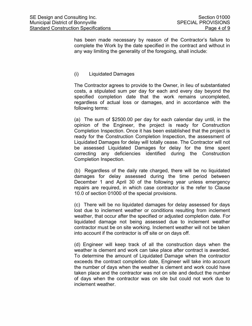
SE Design and Consulting Inc. Section 01000 Municipal District of Bonnyville SPECIAL PROVISIONS Standard Construction Specifications Page 4 of 9
has been made necessary by reason of the Contractor’s failure to complete the Work by the date specified in the contract and without in any way limiting the generality of the foregoing, shall include:
(i) Liquidated Damages
The Contractor agrees to provide to the Owner, in lieu of substantiated costs, a stipulated sum per day for each and every day beyond the specified completion date that the work remains uncompleted, regardless of actual loss or damages, and in accordance with the following terms: (a) The sum of $2500.00 per day for each calendar day until, in the opinion of the Engineer, the project is ready for Construction Completion Inspection. Once it has been established that the project is ready for the Construction Completion Inspection, the assessment of Liquidated Damages for delay will totally cease. The Contractor will not be assessed Liquidated Damages for delay for the time spent correcting any deficiencies identified during the Construction Completion Inspection. (b) Regardless of the daily rate charged, there will be no liquidated damages for delay assessed during the time period between December 1 and April 30 of the following year unless emergency repairs are required, in which case contractor is the refer to Clause 10.0 of section 01000 of the special provisions. (c) There will be no liquidated damages for delay assessed for days lost due to inclement weather or conditions resulting from inclement weather, that occur after the specified or adjusted completion date. For liquidated damage not being assessed due to inclement weather contractor must be on site working. Inclement weather will not be taken into account if the contractor is off site or on days off. (d) Engineer will keep track of all the construction days when the weather is clement and work can take place after contract is awarded. To determine the amount of Liquidated Damage when the contractor exceeds the contract completion date, Engineer will take into account the number of days when the weather is clement and work could have taken place and the contractor was not on site and deduct the number of days when the contractor was on site but could not work due to inclement weather.

SE Design and Consulting Inc. Section 01000 Municipal District of Bonnyville SPECIAL PROVISIONS Standard Construction Specifications Page 5 of 9
For example:
If there are 30 construction days when the weather is clement and the contractor is not on site but could have work and there are 15 days of inclement weather when the contractor was on site but could not work and the contractor is 10 days over the contract completion date the liquidated damage would be 10 days x $2,500.00 = $25,000.00
If there are 20 construction days when the weather is clement and the contractor is not on site but could have work and there are 25 days of inclement weather when the contractor was on site but could not work and the contractor is 10 days over the contract completion date the liquidated damage would be 5 days x $2,500.00 = $12,500.00.
If the contract completion date is the 31st Oct and on the 1st November the work could no longer be completed due to inclement weather, and it takes 20 days to complete the work the following spring assuming there are no inclement weather days in the spring, the liquidated damage would be 20 days x $2,500.00 = $50,000.00.
(ii) Actual Loss or Damages In addition to the daily stipulated sum for Liquidated Damages, as set out in (i), above, the Contractor agrees to provide to the Owner, the actual loss or damages suffered by the Owner for each and every day beyond the specified completion date the Work remains uncompleted for the following items: (a) The additional cost of maintenance and repair necessary; and (b) The cost of accommodating traffic over, through or around portions of Work. (c) The cost of engineering to monitor the ongoing work until such time as the work is completed and meet the approval of the Engineer. The Owner will deduct assessed amounts from payments due on this contract. If there are insufficient funds to cover the assed amounts, the Owner will invoice the Contractor. The Contractor shall promptly pay the amounts invoiced. Should any amount remain unpaid after 60 days from the date of invoice, the Owner may recover such unpaid sum from
SE Design and Consulting Inc. Section 01000 Municipal District of Bonnyville SPECIAL PROVISIONS Standard Construction Specifications Page 6 of 9
any money due to the Contractor from the Owner on any Contract or account, rendering an accounting to the Contractor for any sums so recovered.
.2 The Municipal District of Bonnyville reserves the right to extend the
completion date without penalty, for extenuating circumstances.
11.0 EMERGENCY REPAIRS DURING WARRANTY PERIOD
Further to Article 26 of the General Conditions, in the case of Emergency Repairs, causing significant failures or hazards to the public as determined by the Engineer and/or the Owner during the Warranty Period, the Owner may, without prejudice to any other remedy he may have, correct such repairs.
The cost of Work performed by the Owner in correcting the Emergency Repairs shall be paid by the Contractor. The cost may include but not limited to:
(a) The cost of maintenance and repair necessary carried out by the owner. Cost may include but not limited to: Supervision, labour, material, equipment. (b) The cost of accommodating traffic over, through or around portions of Work. (c) The cost of engineering to monitor the ongoing repairs and report daily to the Owner until such time as the repair is completed and meet the approval of the Engineer. (d) The cost of contracting if the Owner cannot do the repairs with his own resources. (e) The cost of rental equipment if applicable. (f) All work carried out by the Contractor to repair the damaged area will be at his/her own cost.
The work must be restored as per the terms of the contract. The Owner will deduct assessed amounts from payments due on this contract. If there are insufficient funds to cover the assed amounts, the Owner will invoice the Contractor. The Contractor shall promptly pay the amount invoiced. Should any amount remain unpaid after 60 days from the date of invoice, the Owner may recover such unpaid sum from the contractor performance bond.

SE Design and Consulting Inc. Section 01000 Municipal District of Bonnyville SPECIAL PROVISIONS Standard Construction Specifications Page 7 of 9
12.0 FAILED PROOF ROLLS
.1 This test will be undertaken when the compaction of the subgrade has been completed, and shall be under the direction and in the presence of the Contractor, Engineer and the Owner.
.2 If this test fails where a proof roll must be re-schedule with the
Engineer and the Owner, the cost of engineering and the owner’s time to redo the proof roll shall be paid by the Contractor.
13.0 REVISIONS TO TENDERS
.1 Revisions to the tender by FAX 780-826-5064 will be accepted if received prior to the specified closing time to the office of the Municipal District of Bonnyville on the date the tenders close.
.2 Faxed tenders will be accepted only if the original of the tender security
is delivered to the office of the Municipal District of Bonnyville prior to the specified closing time on the date the tenders close.
14.0 TRUCK WEIGHT SCALES (IF REQUIRED)
.1 If contractor has to supply their own aggregates, the Contractor shall at his own expense provide platform scales and a scale house
.2 The platform scales shall be of sufficient length and capacity to
accommodate any truck, including pups or trailers, used on the contract in a single weighing.
.3 The Contractor’s weight scales shall be tested and certified by Weights
and Measures Inspection Services of the Federal Department of Consumer and Corporate Affairs.
.4 The scales shall be tested prior to their use on this contract and as
frequently as Engineer may deem necessary in order to ensure their accuracy.
.5 Except for the first certification of the season, weigh scales may be
tested by the Contractor’s project personnel provided that the Contractor uses the proper weights and testing.
.6 The Contractor may also verify the weigh scales by comparing the
weight of a loaded vehicle over an operating provincial weigh scale provided that the tare weight remains unchanged for both weightings.
.7 The scale house shall be weatherproof, heated and large enough to

SE Design and Consulting Inc. Section 01000 Municipal District of Bonnyville SPECIAL PROVISIONS Standard Construction Specifications Page 8 of 9
provide reasonable working accommodation for the scale operator and required furnishings.
.8 The inspection certificate issued for the current year shall be provided to the Engineer.
.9 The Contractor will provide at his expense a scale person at the
Contractor weigh scales for the purposes of weighing materials. .10 The weights so determined shall be the basis for measurement for
payment.
15.0 TRAFFIC
.1 The Contractor shall perform the construction operations such that traffic disruptions are minimized. Contractor to submit traffic accommodation plan to the Engineer for approval prior to start of construction.
.2 All effort should be made to detour the traffic using existing roads where practical. This must be reflected on the traffic accommodation plan.
.3 If a detour road must be constructed, the contractor will be responsible for the construction of this detour road at his own cost and he will be responsible for the maintenance of that detour road for as long as the detour road is required. Contractor will be responsible to remove this detour road and restore the ground to it’s original state prior to completion of the project. Contractor to account for this cost on the line item: Traffic Accommodation on the schedule of quantities.
.4 The Contractor will be responsible to provide adequate signage to
detour traffic from the construction zones. The Contractor may refer to Alberta Transportations standards for traffic accommodation in urban work zones for details of construction signage. Those signage must be identified on the traffic accommodation plan.
.5 The Contractor may request the Engineer to restrict traffic access to
local traffic only. .6 The Contractor will be required to maintain access for local traffic and
emergency traffic at all times. .7 Provide 48 hours notice to affected residents who may temporarily lose
vehicular access to their properties.

SE Design and Consulting Inc. Section 01000 Municipal District of Bonnyville SPECIAL PROVISIONS Standard Construction Specifications Page 9 of 9
.8 The Contractor may request to the Engineer to detour local traffic through lanes.
.9 Provide any necessary flagmen to control traffic flow during the
construction operations.
16.0 QUALITY CONTROL TESTING
.1 The Contractor will be responsible for providing and paying for all standard quality control testing. Client will pay for material testing, and asphalt coring.
.2 The quality control testing firm shall be approved by the Engineer. .3 Copies of results for any quality control testing carried out by the
contractor shall be forwarded directly to the Engineer. .4 Where tests or inspections by the designated testing firm reveal work
not in accordance with contract requirements, Contractor shall pay costs for additional tests or inspections as Engineer may require to verify acceptability of corrected work.
.5 Contractor’s Responsibilities .1 Provide access to work to be inspected and tested. .2 Cooperate to provide reasonable facilities for such access. .3 Facilitate inspections and tests. .4 Make good work disturbed by inspection and tests.
.5 Notify the appropriate agency and Engineer in advance of the requirement for tests, in order that attendance arrangements can be made.
.6 Submit samples and / or materials required for testing, as
specifically requested in specifications. Submit with reasonable promptness and in an orderly sequence so as not to cause delay in the work.
.7 Provide labour and facilities to obtain and handle samples and
materials on site. Provide sufficient space to store and cure test samples.
END OF SECTION

SE Design and Consulting Inc. Section 01005 Municipal District of Bonnyville GENERAL INSTRUCTIONS Standard Construction Specifications Page 1 of 5
1.0 DESCRIPTION OF WORK
.1 Work under this contract covers the supply of all labour, equipment, materials and supervision required to bring this project to a successful completion. This specification covers the work under the drawing set provided as part of this contract.
2.0 DOCUMENTS REQUIRED
.1 Maintain at job site, one copy of each of the following: .1 Contract drawings .2 Specifications .3 Addenda .4 Reviewed shop drawings .5 Change orders .6 Other modifications to Contract .7 Field test reports .8 Copy of approved work schedule .9 Copy of any Environmental Approvals .10 Manufacturers' installation and application instructions .11 Standards listed in Part 1 of Specification Section under
Reference Standards
3.0 SITE CONDITIONS
.1 The Contractor shall examine the Work site before submitting his tender, to satisfy himself as to the local existing conditions and nature of work. The Contractor shall not seek nor receive any compensation for failing to investigate the site conditions.
.2 The Contractor shall make allowance for adverse conditions which may exist. The Contractor shall make itself familiar with such conditions. No extra claims or compensation will be allowed for adverse surface conditions.
4.0 PRODUCTS SUPPLIED BY OWNER
.1 No products will be supplied by Owner.
5.0 WORK SCHEDULE
.1 Provide within 7 calendar days after Contract award, schedule showing anticipated progress stages and final completion of work within time period required by Contract documents.
.2 Interim reviews of work progress based on work schedule will be
conducted as decided by Engineer and schedule updated by Contractor in conjunction with and to approval of Engineer.

SE Design and Consulting Inc. Section 01005 Municipal District of Bonnyville GENERAL INSTRUCTIONS Standard Construction Specifications Page 2 of 5
6.0 COST BREAKDOWN
.1 Before submitting first progress claim submit breakdown of Contract price in detail as directed by Engineer and aggregating contract price. After approval by Engineer cost breakdown will be used as basis for progress payment.
7.0 MEASUREMENT OF PAYMENT
.1 Notify Engineer sufficiently in advance of operations to permit required measurement for payment.
8.0 CONTRACTOR'S USE OF SITE
.1 Use of site: limited to working areas and public land as shown on the drawings for work and storage.
.2 Do not unreasonably encumber site with materials or equipment. .3 Move stored products or equipment which interferes with operations of
Engineer or other contractors. .4 If the Contractor requires access to private land to conduct his/her
activity, (for example using land as laydown area, or spill pile dirt from excavation), contractor is to make sure the terms are made clear in writing and signed by the land owner and the contractor. Terms of the agreement must indicate what is agreed upon between both parties and restauration that is required after work is completed. A copy of this agreement must be provided to the Engineer. Contractor to note that the Owner will be absolved of any responsibility towards potential claim that may occur between the land owner and the contractor. Contractor to refer to sample land use agreement in Appendix.
9.0 CODES AND STANDARDS
.1 Perform work in accordance with any applicable federal, provincial or municipal codes provided that in any case of conflict or discrepancy, more stringent requirements shall apply.
.2 Meet or exceed requirements of specified standards, codes and
referenced documents.
10.0 PROJECT MEETINGS
.1 Engineer will arrange project meetings and assume responsibility for setting times and recording and distributing minutes.

SE Design and Consulting Inc. Section 01005 Municipal District of Bonnyville GENERAL INSTRUCTIONS Standard Construction Specifications Page 3 of 5
11.0 CLIENT / CONTRACTOR / ENGINEER COMMUNICATION
1. Contractor is under no circumstances authorized to communicate directly with the Client. All communications and/or questions are to be directed to the Engineer.
2. The Engineer is the only contractual authority that can communicate
with the Client.
3. Contractor is to be notified that if he/she makes a contractual arrangement with the client without the presence of the Engineer who is the contractual authority, the contractor may not be financially compensated for his/her effort.
12.0 LOCATION OF EQUIPMENT AND FIXTURES
.1 Location of equipment, fixtures and outlets indicated or specified are to be considered as approximate.
.2 Locate equipment, fixtures and distribution systems to provide
minimum interference and maximum usable space and in accordance with manufacturer's recommendations for safety, access and maintenance.
.3 Inform Engineer of impending installation and obtain his approval for
actual location. .4 Submit field drawing to indicate relative position of various services
and equipment when required by Engineer.
13.0 CONCEALMENT
.1 Conceal pipes, ducts and wiring in floor, wall and ceiling construction of finished areas except where indicated otherwise.
14.0 CUTTING, FITTING AND PATCHING
.1 Execute cutting (including excavation), fitting and patching required to make work fit properly together.
.2 Where new work connects with existing and where existing work is
altered, cut, patch and make good to match existing work. .3 Obtain Engineer's approval before cutting, boring or sleeving load-
bearing members. .4 Make cuts with clean, true, smooth edges. Make patches

SE Design and Consulting Inc. Section 01005 Municipal District of Bonnyville GENERAL INSTRUCTIONS Standard Construction Specifications Page 4 of 5
inconspicuous in final assembly. .5 Fit work airtight to pipes, sleeves, ducts and conduits.
15.0 EXISTING UTILITIES AND STRUCTURES
.1 The Contractor shall take all necessary precautions to protect from damage all underground and surface structures and services located on the site.
.2 The Contractor shall indemnify and hold harmless the Engineer and
the Owner from all claims made against him in respect of any such damage. The Contractor shall be required to contact all the authorities controlling or owning these structures and services, and satisfy himself as to the locations of the same. If it is necessary to relocate the services because of construction procedures, the Contractor shall be responsible for payment of all costs incurred.
.3 Existing services as shown on the construction drawings are plotted
according to available information but are not guaranteed to be accurate.
.4 The Contractor shall be responsible for inspecting all existing
underground and surface structures prior to the commencement of construction, and shall be responsible for payment for subsequent damages which may occur prior to the final acceptance of the work.
.5 Any poles, signs or other structures that require moving, solely to
facilitate the Contractor’s operation, shall be moved and replaced at the Contractor’s expense.
.6 The Contractor shall be responsible for the protection of all existing
utilities and appurtenances, including but not limited to, power poles, street lights, pad mount transformers, car plug-ins, telephone pedestals, communication lines, legal survey monuments, buried utility conductors, gas lines and buried water, sanitary, and storm sewer mains including services. Extreme caution is to be exercised at all times, and damage is to be reported to the Engineer and repaired immediately. The costs associated with protection of and repair of all utilities and appurtenances shall be borne by the Contractor.
.7 No extra claims or compensation will be allowed for any delay (or
extra) in construction time as caused by efforts exercised in protecting existing utilities and structures.
.8 Before submitting the Bid for this Tender, the Contractor shall contact
the utility companies and/or departments which own or operate the existing underground utilities and structures on site, regarding the standards, procedures and other related requirements with respect to both protection and reparation of the existing underground

SE Design and Consulting Inc. Section 01005 Municipal District of Bonnyville GENERAL INSTRUCTIONS Standard Construction Specifications Page 5 of 5
utilities/structures and restoration of the corresponding, existing utility trenches. The costs associated with protection and reparation of all underground utilities/structures and restoration of utility trenches in meeting the utility companies’ or departments’ standards and other requirements shall be borne by the Contractor and no extra payment will be allowed.
.9 The Engineer reserves the right to charge the Contractor for the costs
in association with works required to protect, repair and restore the existing underground utilities/structures and utility trenches in meeting utility companies’ or departments’ standards and other requirements, if the Contractor fails to do so. The above costs shall be deducted from the contract value or holdback money.
.10 Contractor shall keep all existing utilities operational until the new
connection for the utility is completed. .11 Where work involves breaking into or connecting to existing services,
carry out work at times directed by governing authorities, with minimum of disturbance to pedestrian and vehicular traffic.
.12 Before commencing work, establish location, elevation, size, type and
extent of service lines in area of work and notify Engineer of findings. .13 Submit schedule to and obtain approval from Engineer for any shut-
down or closure of active service or facility. Adhere to approved schedule and provide notice to affected parties. If there is a change in schedule, notify Engineer and provide and updated schedule immediately thereafter.
.14 Where unknown services are encountered, immediately advise
Engineer and confirm findings in writing.
16.0 EMERGENCY VEHICLE ACCESS .1 The Contractor is to maintain access for emergency vehicles during
the construction. The Contractor is to schedule his work accordingly to maintain access for the duration of the project.
17.0 RESTORATION OF LANDSCAPED AREAS .1 The Contractor is responsible for the restoration of all landscaped
areas disturbed by construction activities required by his works.
END OF SECTION

SE Design and Consulting Inc. Section 01501 Municipal District of Bonnyville GENERAL PROJECT REQUIREMENTS Standard Construction Specifications Page 1 of 12
1.0 GENERAL
1.1 Scope .1 This Section describes the general requirements of the Contractor in
the execution of this contract. .2 General Project Requirements refers to the provision of items
incidental to completion of the work for which unit or lump sum prices are not applicable including, bonding, insurance, mobilization, demobilization, maintenance costs, and provision of a site office for the Engineer complete with temporary utilities, as defined within either the General Conditions, the Special Conditions or the detailed specifications within Division 1 – General Requirements.
1.2 Drawings
.1 The current Drawings are indicated in the Table of Contents and these, along with other Drawings that may be prepared during the course of construction form part of the Contract Documents.
.2 The Drawings show the approximate dimensions and general
requirements of the principal features of the work. Where necessary, as determined by the Engineer, additional Drawings showing further details or alterations will be furnished to the Contractor during the progress of the work.
.3 Any discrepancies found between the Drawings and the specifications
and site conditions or any error or omissions in the Drawings or Specifications shall be immediately reported to the Engineer, who shall promptly correct such error or omission in writing. Any work done by the Contractor after discovery of such discrepancies, errors or omissions shall be done at the Contractor's own expense should changes in the Drawings and/or Specifications be required.
.4 The Contractor shall verify all dimensions, quantities and details shown
on the Drawings, Supplementary Drawings, Schedules or other data received from the Engineer, and shall notify the Engineer of any errors, omissions, conflicts and discrepancies found therein.
.5 Failures to discover and correct errors, conflicts or discrepancies shall
not relieve the Contractor of full responsibility for unsatisfactory work, faulty construction or improper operation resulting therefrom, nor from rectifying such conditions at the Contractor’s own expense.
1.3 Historical Resources
.1 Historical resources, as defined by the Historical Resources Act, or other objects of historical significance found on site will remain the property of the Owner, Province or Federal authority.
.2 The Contractor shall protect such articles and request directions from
the Engineer.

SE Design and Consulting Inc. Section 01501 Municipal District of Bonnyville GENERAL PROJECT REQUIREMENTS Standard Construction Specifications Page 2 of 12
1.4 Fair Wages
.1 The Contractor shall, in carrying out this Contract, pay fair wages and
comply with and fix working conditions, with respect to each employee or class of employment, not less favorable than the wages and working conditions established in the area of the General Contractor's Association and/or the Association of the Industry.
1.5 Health and Safety
.1 The Contractor shall designated the “Prime Contractor” as defined in the Occupational Health and Safety Act and shall be responsible for all duties prescribed thereunder.
1.6 Environmental Protection
.1 The Contractor must conduct himself in accordance with all federal, provincial or municipal environmental legislation.
.2 The Contractor shall perform the work in accordance with all approvals
received from any federal, provincial or municipal authorities. .3 All work shall be performed in accordance with the Development and
Reclamation Application as approved by Alberta Environment. 1.7 Holidays
.1 The Contractor shall not work on any Sunday or on any other day normally observed as a holiday without the Engineer’s approval.
1.8 Night Work
.1 Night work will only be allowed if the Engineer gives written permission, in accordance with the municipal authorities' Bylaws. When work is carried out at night, the Contractor must supply all equipment necessary for the illumination and the safe and satisfactory working in the area designated for the night work.
2.0 PRODUCTS 2.1 General Instructions
.1 Prior to commencing actual construction, the Contractor shall check field conditions to obtain actual dimensions required to ensure correct fabrication and execution of the work, and notify the Engineer in writing, of all matters, which could prejudice proper execution of the work. Commencement of construction shall constitute acceptance of existing conditions, and verification of dimensions.
.2 Where work of this Contract involves breaking into or connecting to
existing services or utilities, the Contractor shall carry out work as directed by governing authorities, with a minimum of disturbance to the public.

SE Design and Consulting Inc. Section 01501 Municipal District of Bonnyville GENERAL PROJECT REQUIREMENTS Standard Construction Specifications Page 3 of 12
2.2 Alternates
.1 Quality - In order to establish standards of quality, the Engineer may have, in the Specifications and/or Drawings, referred to the products by name. This procedure is not to be construed as eliminating other products of equal or better quality. The Engineer will be the sole judge as to the acceptability of substitute materials.
2.3 Materials Supplied by the Contractor
.1 All materials used in the work shall meet the requirements of the respective Specifications. The Contractor shall supply all materials not otherwise specifically indicated.
3.0 EXECUTION
3.1 Co-ordination of Work
.1 The Contractor shall be responsible for the co-ordination of all aspects of the completed work.
.2 The Contractor shall confine his plant and equipment, the storage of
materials and the operations of his workmen to limits indicated by law, ordinances, permits or directions of the Engineer and shall not unreasonably encumber the work areas with his materials.
.3 The Contractor shall permit full use, without charge therefore, by the
Owner and/or other Contractors of any facilities usable jointly. .4 The Owner and/or other Contractors may perform work at or in the
vicinity of the site during the period covered by the Contract. The Contractor shall co-operate with and co-ordinate his activities with other Contractors in the working area so that the work of all Contractors concerned will proceed unhindered.
.5 No claims for additional payment will be considered on account of
delays, changes in construction schedules or any other reason whatsoever due to the fact that other Contractors are operating in the work areas.
3.2 Project Meetings
.1 Immediately following the Award of Contract, all parties to the Contract shall meet to discuss and resolve administrative procedures and responsibilities. Senior representatives of the Owner, the Engineer, the General Contractor, major Sub-Contractors, Utility Company representatives, provincial officials (as required), all Field Inspectors and Supervisors will be invited to attend.
.2 After award of Contract, the Engineer shall arrange progress meetings
at regular intervals. The Engineer shall prepare minutes of these meetings and circulate to all in attendance and other relevant individuals.

SE Design and Consulting Inc. Section 01501 Municipal District of Bonnyville GENERAL PROJECT REQUIREMENTS Standard Construction Specifications Page 4 of 12
3.3 Construction Program
.1 The Contractor's construction operations shall be subject to the review of the Engineer. The sequence of operations and methods of operation shall be such as to ensure the completion of the work in a timely manner with minimal inconvenience to the public and impact on the environment.
.2 Within seven (7) calendar days after the Contractor has been advised
in writing of the acceptance of his tender, he shall furnish the Engineer with his proposed program of operation and the Contractor shall immediately advise the Engineer of any proposed changes to his construction program. Should the Contractor's work fail to progress according to the applicable progress schedules, the Contractor shall explain the slippage in construction schedule and develop measures to regain the original approved schedule.
3.4 Surveys
.1 The Contractor shall provide the Engineer with all stakes and other materials with the exception of technical instruments, required by the Engineer to establish all horizontal and vertical control for the work. The Contractor shall also supply the Engineer with reasonable assistance and with assistants as required for establishing or checking line and grade as well as measuring quantities.
.2 The Engineer is responsible to establish the baseline with 3m offset at
50m intervals at the start of the project. If manpower is available, the Engineer may provide at the contractor’s expense service above and beyond the baseline. If during construction, the contractor destruct the baseline stakes and want them to be replaced, the Engineer may do so if manpower is available and at the contractor’s expense.
.2 The Contractor shall have the responsibility to carefully preserve
bench marks, reference lines, stakes, grade marks, monuments, legal survey pins and all data pertaining to horizontal and vertical control and in the case of destruction thereof by the Contractor or resulting from his negligence, the Contractor shall be charged with the expense and damage resulting from and shall be responsible for any mistakes that may be caused by the unnecessary loss or disturbance of any horizontal and vertical control.
.4 Legal survey markers, disturbed or removed by the construction
operation, that existed at a horizontal distance of two (2) metres or more from the centreline of pipe being installed or one (1) metre or more of any roadway, sidewalk or curb and gutter shall be replaced at the Contractor's expense by a Registered Land Surveyor. If it is necessary to remove or disturb existing legal survey markers that are within two (2) metres of the pipe centre line or within one (1) metre of any roadway, sidewalk or curb and gutter, the Engineer shall be so notified before such removal and replacement will be at the Owner's

SE Design and Consulting Inc. Section 01501 Municipal District of Bonnyville GENERAL PROJECT REQUIREMENTS Standard Construction Specifications Page 5 of 12
expense. 3.5 Public Safety and Convenience
.1 The Contractor shall at all times conduct the work to ensure the least possible obstruction to traffic, inconvenience to the general public and disturbance of the residents in the vicinity of the work and shall ensure the protection of persons and property.
.2 No road or street shall be closed to the public except with the
permission of the Engineer and proper governmental authority.
.3 Fire hydrants on or adjacent to the work shall be kept accessible to fire-fighting equipment at all times.
.4 Temporary provisions shall be made by the Contractor to ensure the
use of sidewalks and the proper functioning of all gutters, sewer inlets, drainage ditches and irrigation ditches, which shall not be obstructed except as approved by the Engineer.
.5 Control all work site access points and work site activities. Delineate and isolate the work site from adjacent and surrounding areas by use of appropriate means to maintain control of all work site access points. Provide all necessary lighting, fencing, boarding, signage and security personnel to adequately protect the work and the public.
.6 Make provisions for granting permission to access onto work site to all persons who require access. Procedures for granting permission to access are to be in accordance with the Alberta Occupational Health and Safety Act, and the Regulations made pursuant to the Act and the Contractor’s Health and Safety Program.
.7 Ensure persons granted access to the work site are in possession of and wear the minimum personal protective equipment (PPE) designated by the Contractor’s Health and Safety Program and the governing OH & S Legislation. Ensure persons granted access to the work site are provided with, trained in the use of, and wear, appropriate PPE that are required above and beyond the designated minimums previously noted and as specifically related to the work site activity that they are involved in. Be responsible for the efficacy of the PPE that is provided above and beyond the designated minimums.
.8 Install safety fence around active construction site, open excavation that may endanger the public, and as directed by Engineer. Contractor to follow Alberta Health and Safety Regulations and the governing OH&S legislation.

SE Design and Consulting Inc. Section 01501 Municipal District of Bonnyville GENERAL PROJECT REQUIREMENTS Standard Construction Specifications Page 6 of 12
.9 Safety fence shall be a minimum 1.9 m high wire construction fence. Snow fencing around open excavation will not be approved by the Engineer.
3.6 Quality Control .1 An independent inspection firm, appointed by the Engineer and paid
for by the Owner, shall carry out testing. The Contractor shall pay for extra tests required because of non-compliance of the works with the minimum requirements for materials and workmanship.
3.7 Warning Signs and Barricades
.1 The Contractor shall provide adequate signs, barricades, red lights, and watchmen and take all necessary precautions for the protection of the work and the safety of the public. All barricades and obstructions shall be protected at night by signal lights or flares which shall be kept burning from sunset to sunrise. Barricades shall be readily visible at night. Suitable warning signs shall be placed and illuminated at night to show in advance where construction, barricades or detours exist.
.2 Prior to leaving the site for extended periods of time (in excess of 24
hours) the Contractor shall ensure all excavations are backfilled. Alternatively, the Engineer may approve the use of temporary fencing to protect the public from entering open excavations.
3.8 Access Roads
.1 Temporary roads shall be constructed as required for access to the working areas. Adequate drainage facilities in the form of ditches, culverts or other conduits shall be installed, when required for these roads.
.2 In the construction of access roads, existing drainage facilities, natural
or otherwise, shall not be disturbed to the detriment of properties outside the working area and such facilities shall, unless otherwise provided elsewhere in the specifications, be restored to their original condition upon completion of the work.
3.9 Haul Routes
.1 Haul routes used by the Contractor shall be subject to approval by the Owner and Engineer. The Contractor shall be responsible for damage and/or spillage on the roads used for hauling materials and equipment to and from the site, subject to the Engineer being satisfied such damage or spillage was a direct result of the actions of the Contractor or any of the Contractor's agents in the performance of the work required under this Contract. If remedial work is necessary, the Contractor shall immediately clean and/or restore the affected area.

SE Design and Consulting Inc. Section 01501 Municipal District of Bonnyville GENERAL PROJECT REQUIREMENTS Standard Construction Specifications Page 7 of 12
3.10 Water Consumption .1 Water for construction purposes will be obtained from sources
approved by the Engineer. Contractor is responsible to find his/her own water source.
3.11 Business Licence
.1 The Contractor will require a municipal business licence. 3.12 Detours
.1 Where construction requires the blocking or closing of existing roads, a suitable detour with adequate signing and lighting shall be provided. The Contractor shall obtain the approval of the local authority for the proposed closing and the detour route.
.2 The City will notify the police, ambulance and fire departments a
minimum of 48 hours in advance of the road closure and the location of the proposed detour.
.3 The contractor shall provide all detour signs according to Alberta
transportation standards. All signs must meet Alberta Transportation Standard, no contractor made signs will be accepted. Owner will not be responsible for the cost or the supply of the traffic detour signs or the replacement of the signs if they go missing.
3.13 Traffic Control
.1 All traffic signs/devices, traffic channeling, detours, closures, etc. shall be in accordance with the Manual of Uniform Traffic Control Devices as published by the Transportation Association of Canada (TAC) .
.2 All traffic control shall be carried out in accordance with Specification
01502. 3.14 Road Closures
.1 A minimum of one-lane must be open to traffic at all times unless otherwise approved by the Engineer.
.2 The use of parallel roads to accommodate traffic is subject to the
approval of the Engineer. 3.15 Salvaged Utilities
.1 The owner reserves the right and/or dispose of all existing utility material such as hydrants, valves, pipes, etc., that is removed from the site during construction. If the owner wishes to retain some or all existing utility material, they shall remain the property of the Owner and shall be stockpiled and/or disposed of as directed by the Engineer. If the owner does not wish to retain the existing utility material, they shall be disposed by the contractor off the Owner’s property.

SE Design and Consulting Inc. Section 01501 Municipal District of Bonnyville GENERAL PROJECT REQUIREMENTS Standard Construction Specifications Page 8 of 12
3.16 Protection of Existing Surface and Underground Structures
.1 The Contractor shall take all necessary measures to protect any existing structures from injury and damage and shall substantially and sufficiently support all structures that may be endangered by work or other operations carried out as part of the contract.
.2 The existence and location of underground utilities shown on the
Drawings is not guaranteed, and notwithstanding any other provision in the Contract and without limiting the generality of the foregoing, sewer, water and gas mains or lines, electric light, power, or telephone conduits, or other such structures of utilities must be located by the Contractor, and failure to locate same does not negate the Contractor's responsibility thereto. The Contractor shall pay any charges to the Utility Companies in this regard. The Contractor shall make arrangements with the Owner of any underground structure to be present to supervise the work adjacent to the structure. Should any structures be injured by the aforementioned operation, they shall be restored at the expense of the Contractor to an operable state, or as specified by the Engineer, within the same working day as such disruption occurred.
.3 Permanent repair must be completed during the next working day, to
the satisfaction of the Engineer. 3.17 Blasting
.1 Blasting will be permitted only after securing the approval of the Owner and/or local authority. The Contractor at his expense shall repair damage caused by blasting. The method and procedure employed for blasting shall be in accordance with federal, provincial, and municipal laws and regulations. The Contractor shall not do any blasting without first verifying that his insurance covers any loss of life or damage that may result from this work. The Owner, in granting approval for blasting, does not in any way assume responsibility for injury, loss of life, or damage that may result therefrom, and such approval shall not be construed as approval of the methods employed by the Contractor in blasting, the sole responsibility therefor being that of the Contractor.
3.18 Special Controls
.1 The Contractor shall perform the work in conformity with all municipal by-laws with respect to noise, hours of work, night work and holiday work. Night work and holiday work requires the written permission of the Owner.
.2 The Contractor shall perform the work in a manner that will not
produce an objectionable amount of dust. Dust control shall be performed to the satisfaction of the Engineer and there will be no separate or additional payment for this work but it shall be considered incidental to the remaining work under the Contract.

SE Design and Consulting Inc. Section 01501 Municipal District of Bonnyville GENERAL PROJECT REQUIREMENTS Standard Construction Specifications Page 9 of 12
.3 The Contractor shall perform all work in conformity with the
Environmental Protection and Enhancement Act and all existing municipal bylaws.
3.19 Construction Affecting Residential Areas
.1 The Contractor shall provide suitable traffic control for pedestrians, cyclists and motorists, which will protect the public and maintain access to local traffic with as little disruption as possible.
.2 All proposed routes for hauling equipment must be approved by the
Engineer prior to commencement of the work. Rubber tired motor scrapers shall not be used to haul over improved streets or gas lines. When any travelled roadway is being entered or crossed by hauling equipment, traffic must be controlled by qualified flag persons and sufficient warning signs to ensure the safety of the public.
.3 Trucks must be loaded in such a manner that no spillage occurs during
haul. Care must be taken to prevent the deposition of soil onto existing streets and roads. The clean-up of soil deposition must be performed prior to the end of each day’s haul or as directed by the Engineer.
.4 All public relations elements inclusive of open houses, advertisements,
notices, other information requirements, emergency contract personnel, emergency response personnel, public relations telecommunications equipment, emergency telecommunications equipment whether on-site or off-site shall be the responsibility of the Contractor. The Contractor shall submit to the Owner, in writing, his proposed public relations strategy and personnel for Owner approval prior to proceeding with construction.
.5 Notify, in writing, every business or resident whose property is fronting,
backing or immediately adjacent to the construction site, at least seven (7) days in advance for construction in the affected area. Notices shall be printed on the Contractor's letterhead and submitted to the Engineer for his approval prior to delivery to businesses or residents.
.6 Contractor notices shall give approximate date of construction in
affected areas and clearly indicate the Contractor's name, address and telephone number, as well as a telephone number which residents can call for 24-hour emergency service. The notice shall also include a contact person's name for reporting damage to personal property, alternative parking, access, and garbage disposal and temporary water or sewer systems. The Contractor shall also provide notice, warning parents of the dangers that exist on construction site and shall deliver this to every household in the vicinity of construction.
.7 In the event that it should become necessary to disrupt water or
sanitary services to any residences during the course of construction,

SE Design and Consulting Inc. Section 01501 Municipal District of Bonnyville GENERAL PROJECT REQUIREMENTS Standard Construction Specifications Page 10 of 12
the Contractor shall give 48-hour written notice of the intended disruption to all affected residences or businesses. The notice shall be delivered to an adult member of the residence or business.
.8 If the date of garbage collection falls within the lane/street closure
period, the Contractor shall make arrangements for removing the garbage to a location where sanitation trucks can pick up the garbage without driving on the closed road or excavated area. The Contractor shall co-ordinate this activity with the Owner and shall have Owner approval of proposed strategy for garbage collection.
.9 The Contractor shall be responsible for providing, maintaining,
protecting and repairing temporary utility (water, sewer, gas, power, telephone and other utility) services.
.10 During construction and warranty periods, if the Contractor fails to
respond to customer's (property owner's) requests for remedial works regarding maintaining (or repairing) temporary utility services or correcting faulty works (or products), within a reasonable time (i.e. one to two hours), the Owner shall have the right to carry out the necessary remedial works (by Owner forces or other Contractors) in this regard and shall charge the costs of the remedial works done to the Contractor or deduct the costs of the remedial works from the contract value or holdback monies due to the Contractor.
.11 The Contractor shall be responsible for providing temporary parking
spaces for property owners and customers whose access to their normal parking spaces (i.e. garages, parking lots, etc.) are affected by construction on site.
.12 The Contractor shall be responsible for providing temporary accesses
to private/public properties in which accesses to the property (i.e. sidewalks, driveways, para-ramps, etc.) are affected by construction on site.
.13 During construction periods, if the Contractor fails to respond to
customer's (property owner's) requests for providing temporary access to his or her property(s) within a reasonable time (i.e. one to two hours), the Owner shall have the right to carry out the necessary remedial works (by Owner forces or other Contractors) in this regard and shall charge the costs of the remedial works done to the Contractor or deduct the costs of the remedial works from the contract value or holdback monies due to the Contractor.
.14 This section shall apply to all areas of this project.
3.20 Site Maintenance and Cleanup
.1 The working area shall be maintained in an orderly manner and shall not be encumbered with equipment, materials or debris.

SE Design and Consulting Inc. Section 01501 Municipal District of Bonnyville GENERAL PROJECT REQUIREMENTS Standard Construction Specifications Page 11 of 12
.2 Clean up shall be a continuing process from the start of the work to the
final acceptance of the project. .3 The Contractor shall at all times, and without further order, keep
property on which work is in progress free from accumulations of waste materials or rubbish caused by employees or by the work. Accumulations of waste materials, which might constitute a fire hazard, will not be permitted. Spillage from the Contractor's hauling vehicles on travelled public or private roads shall be promptly cleaned up. On completion of construction, the Contractor shall remove all temporary structures, rubbish, and waste materials resulting from his operations.
3.21 Access to Private Property
.1 The Contractor shall provide and maintain reasonable access to all private property and places of business. When actual construction operations prohibit provisions of such access the Contractor shall notify, well in advance, any residents and businesses affected by the closure.
3.22 Project Closeout
.1 The Contractor and his Sub-contractors shall conduct an inspection of the Work and correct all deficiencies. The Contractor shall notify the Engineer in writing of satisfactory completion of the "Contractor's Inspection" and request an Engineer Inspection. The Engineer's inspection shall consist of the Engineering team and the Contractor. During the "Engineer's Inspection" a list of all deficiencies shall be drawn up and signed by the Engineer. The Contractor shall correct all deficiencies in a satisfactory manner. When the Contractor is satisfied that all deficiencies have been corrected, the Contractor shall request, in writing, a "Final Inspection". The Final Inspection Team shall consist of the Owner, Engineer and the Contractor.
.2 When the Final Inspection team mutually agrees that the work is
completed, the Contractor shall issue a written declaration to the Owner as follows:
All work in respect to the Contract for the (Name of Project) and
identified as Engineer's Job No. (Job No.), has been completed as of (Day, Month, Year) and no further work is required except for repairs or replacements as set out in the General Conditions.
.3 The Engineer will state in writing, upon agreement with the above
declaration, his approval of the inspected work, and issue a Construction Completion Certificate. The Engineer may at any time before issuance of a Construction Completion Certificate, describe the portions of the Work not completed to his satisfaction and all things which must be done by the Contractor before a Construction Completion Certificate will be issued.

SE Design and Consulting Inc. Section 01501 Municipal District of Bonnyville GENERAL PROJECT REQUIREMENTS Standard Construction Specifications Page 12 of 12
.4 Immediately prior to expiration of the relevant maintenance period, the
Contractor shall request in writing, a joint inspection of the work, by the Final Inspection Team. The Engineer will thereafter, on being satisfied that all necessary maintenance has been completed, issue a Certificate of Total Performance.
4.0 PAYMENT 4.1 General
.1 Unless otherwise provided in the Tender Form there shall be no separate or additional payment for work required under this Section but it shall be considered incidental to the remaining work under this Contract.
.2 Where indicated in the Tender Form, payment for General Project
Requirements shall be made in accordance with the following schedule:
(a) Fifty percent (50%) of the lump sum tender price shall be included
in the first progress report payment certificate for the schedule.
(b) The remaining fifty percent (50%) shall be paid out upon substantial completion of the project.
END OF SECTION

SE Design and Consulting Inc. Section 01502 Municipal District of Bonnyville TRAFFIC ACCOMODATION Standard Construction Specifications Page 1 of 4
1.0 GENERAL 1.1 Traffic Accomodation
.1 Make suitable provisions, including the use of detours, to accommodate all vehicular and pedestrian traffic safely and with a minimum of inconvenience through and around the work.
.2 Provide, install, maintain and protect traffic control devices such as
signs, barriers, fences and lights as required to perform the work safely.
.3 Provide the required number of flagpersons, during all periods of active
equipment operations which may affect normal traffic operations. .4 Control operations to ensure normal school bus operations are not
interfered with. .5 Ensure uninterrupted access to developments along the project. .6 Obtain prior approval of the Engineer before changing or disrupting
existing accesses and road crossings. .7 Carry out construction operations in one continuous operation at road
crossings, intersections and entrances for each phase of the work. .8 Provide and use such other methods or equipment necessary to
accommodate traffic safely through the work site. .9 The Engineer has the right to require the Contractor to modify
operations if, in the opinion of the Engineer, traffic is being unduly hindered or public safety is being compromised.
.10 The Contractor shall promptly make any modifications to the traffic
accommodation operations deemed necessary by the Engineer. .11 The Engineer may suspend work, where in the Engineer’s opinion, the
Contractor fails to adequately provide for the safety of the public, for re-occurring safety issues or when the Contractor fails to comply with orders issued by the Engineer regarding traffic accommodation operations.
.12 The Contractor shall remove or cover all traffic control devices when
not essential for the safe accommodation of traffic, in order to eliminate unnecessary inconvenience to the traffic.

SE Design and Consulting Inc. Section 01502 Municipal District of Bonnyville TRAFFIC ACCOMODATION Standard Construction Specifications Page 2 of 4
.13 The Contractor shall coordinate his traffic accommodation measures
with those of other forces at or adjacent to the work, as required, to accommodate traffic safely and conveniently. This shall not relieve the Contractor of the responsibility for the safe accommodation of traffic over the whole of the work.
.14 Prior to any prolonged shut down of construction, the Contractor shall
ensure that any disturbed roadway surface is restored to a condition suitable for traffic operations approved by the Engineer.
15. The contractor shall provide all detour signs according to Alberta
transportation standards. All signs must meet Alberta Transportation Standard, contractor made signs will not be accepted. Owner will not be responsible for the cost or the supply of the traffic detour signs.
.16 The Contractor shall provide adequate signs, barricades, red lights,
and watchmen and take all necessary precautions for the protection of the work and the safety of the public. All barricades and obstructions shall be protected at night by signal lights or flares which shall be kept burning from sunset to sunrise. Barricades shall be readily visible at night. Suitable warning signs shall be placed and illuminated at night to show in advance where construction, barricades or detours exist.
1.2 Flagpersons
.1 When construction operations or work zone conditions cause interruption, delay or hazard to the traveling public or anyone on the worksite, that requires the use of flagpersons, responsible flagpersons shall be continuously maintained for the direction and control of traffic.
.2 The Contractor shall ensure that flagpersons are instructed in and use
proper traffic control procedures appropriate for the prevailing conditions.
.3 Flagpersons shall have proof of certification from a recognized training
program on traffic control procedures through construction zones. .4 Flagpersons shall be dressed in clean uniforms or coveralls, orange
hardhats and fluorescent red-orange overvests for maximum visibility and shall be equipped with proper traffic control paddles.
.5 During hours of darkness, flagpersons shall be additionally equipped
with a red signal hand-light with sufficient brightness to be clearly visible to approaching traffic and flagging stations shall be illuminated by overhead lighting.
.6 During hours of darkness, signs indicating hazardous conditions and
signs requiring increased attention shall be marked with flashers.
SE Design and Consulting Inc. Section 01502 Municipal District of Bonnyville TRAFFIC ACCOMODATION Standard Construction Specifications Page 3 of 4
1.3. Removal, Salvage and Replacement
of Existing Signs and Guideposts
.1 All existing signs and guideposts which must be removed in the prosecution of the work shall be carefully salvaged by the Contractor.
.2 Critical signs necessary for the protection of traffic such as stop signs
shall be maintained. .3 All signs shall be replaced as soon as possible after the completion of
the work. 1.4. Detour Road and Roadway Maintenance
.1 Subject to the approval of the Engineer, detours may be used to carry traffic around the worksite.
.2 Construction of the detour road is part of the contract and is covered
under line item – Traffic Accommodation on the schedule of quantities. As well maintenance of the detour road during construction is the contractor’s responsibility and is part of the Traffic Accommodation line item on the schedule of quantities.
.3 When the work required disturbance of an existing roadway carrying
public traffic, the Contractor shall keep the disturbed areas of the travel lanes well graded, free of potholes and of sufficient width for the required number of travel lanes.
.4 Prior to any prolonged shut down of construction, the Contractor shall
ensure that any disturbed roadway surface is restored to a condition suitable for traffic operations as approved by the Engineer.
.5 When traffic is diverted entirely off the right-of-way, the Contractor
shall establish and maintain a detour which shall be complete with signs at every intersection.
.6 When in the opinion of the Engineer surfacing gravel is required for
traffic accommodation on areas disturbed by the Contractor prior to the completion of the work on those areas, the Contractor shall promptly provide and place crushed surfacing gravel to the satisfaction of the Engineer.
.7 When a secondary or local road is used as a detour, the Contractor
shall maintain and leave it in a condition as good as it was, in the opinion of the Engineer, prior to its use as a detour, including resurfacing if required.
.8 If the Contractor fails to promptly maintain the road and apply gravel,
the Engineer may make other arrangements to have the work done

SE Design and Consulting Inc. Section 01502 Municipal District of Bonnyville TRAFFIC ACCOMODATION Standard Construction Specifications Page 4 of 4
and deduct the cost thereof from any money owing to the Contractor. 1.5. Dust Abatement
.1 The Contractor shall keep detours and roadways within the project limits free of excessive dust.
.2 The Contractor shall supply and apply all dust abatement material. .3 If the Contractor fails to promptly undertake dust abatement measures,
the Engineer may make other arrangements to have the work done and deduct the cost thereof from any money owing to the Contractor.
END OF SECTION

SE Design and Consulting Inc. Section 01503 Municipal District of Bonnyville SAFEGUARDING UTILITY INSTALLATIONS Standard Construction Specifications Page 1 of 5
1.0 GENERAL
1.1 Contractor’s Responsibility .1 The Contractor shall assume full responsibility for safeguarding all
existing and relocated utility installations during the progress of the work.
.2 “Utility installations” shall mean: Utilities and facilities which are located on, in or near the right-of-way
and which may be affected by the construction and shall include but not be limited to pipelines, drainage works, irrigation works, water works, sewage works, power facilities, telephone facilities, cable facilities and related appurtenances.
.3 While the Engineer has made every effort to collect and present
complete details concerning utility installations, no responsibility will be assumed by the Engineer for the correctness and completeness of its information and the Contractor shall have no claim on that account.
1.2 Liaison and Location
.1 The Contractor shall be responsible to ensure that all utility installations are located and clearly marked on the ground before commencing construction operations.
.2 The Engineer may provide information respecting known utilities but
the Contractor shall be responsible for contacting all affected utility owners or operators to determine the existence and location of all utility installations, maintaining liaison with the utility owners or operators concerning adjustment of the utilities and coordinate construction accordingly.
1.3 Precautionary Measures
.1 The Contractor shall take all precautionary measures as may be necessary when working over or adjacent to utility installations whether above or below ground and shall control equipment and method of construction to prevent damage to any utility and its appurtenances.
.2 Under no circumstances shall the Contractor carry out any
construction operations over or adjacent to any utility until the required adjustments and protection as required for the proposed construction have been completed.
.3 The Contractor shall provide a minimum of 48 hours (excluding
weekends and holidays) notice to the utility owner or operator in advance of commencing construction operations that may affect their installations.
.4 After completion of utility work by the owner or operator the Contractor
shall continue to work in close liaison with the utility owner or operator

SE Design and Consulting Inc. Section 01503 Municipal District of Bonnyville SAFEGUARDING UTILITY INSTALLATIONS Standard Construction Specifications Page 2 of 5
and, if the utility owner or operator so requires, ensure that a representative of the affected utility owner or operator is present at all times during active equipment operations at that location.
.5 The Contractor shall ensure that no equipment crosses or operates
over or under any utility installations at locations other than where required protection has specifically been provided and shall work in close cooperation with the utility owner or operator in the execution of the work.
.6 When construction is undertaken in the vicinity of any unprotected
utility installation, the Contractor shall exercise extreme caution to ensure that the utility installation is not damaged by construction equipment or applied loads.
.7 When haul roads or equipment crossings are required it shall be the
Contractor’s responsibility to determine, provide and install any protective works necessary and to observe any other precautions which may be required
1.4 Telephone Facilities
.1 When there are telephone facilities which are affected by the work, the applicable telephone company may carry out the required relocation of their facilities concurrently with the Contractor’s operations.
.2 In those areas where it is not immediately feasible to relocate buried
cable to the final location, the telephone company may temporarily place cable on the surface and bury it upon completion of construction operations.
1.5 Power Facilities
.1 When there are power facilities within the limits of this project, alterations will be carried out by the applicable power company concurrently with construction operations.
.2 The Contractor, in undertaking any work near existing power facilities
shall comply with the requirements under the Electrical Protection Act and associated regulations.
.3 Prior to the commencement of power facility relocation the Contractor
shall first carry out necessary clearing and grubbing. .4 The Contractor may be required to undertake additional clearing and
grubbing to accommodate the relocated power facilities, payment for which will be made at the applicable unit prices.
.5 When the Contract does not contain bid items for clearing or clearing
and grubbing, any required clearing or clearing and grubbing will be considered incidental to the work.

SE Design and Consulting Inc. Section 01503 Municipal District of Bonnyville SAFEGUARDING UTILITY INSTALLATIONS Standard Construction Specifications Page 3 of 5
.6 It shall be the Contractor’s responsibility to maintain liaison with the power company to ensure that the necessary land clearances have been arranged.
1.6 Pipelines
.1 The companies named within the Special Provisions have pipelines located within the limits of the project and any required adjustments will be carried out by the owner or operator concurrently with construction operations.
.2 When the magnitude and degree of complexity of any required
adjustments prevents the Contractor from working in the vicinity of the pipeline, the Contractor shall arrange operations clear of the those pipelines until the required adjustments are completed and permission to construct in their vicinity is received.
.3 The Contractor shall not have any claim for compensation or damages
for any stoppage, delays, inconvenience or damage sustained due to any interference for the pipelines or the operation of relocating them.
.4 Prior to the commencement of construction operations, the Contractor
shall review the project with representatives of each pipeline company and the Engineer to determine the location and specifics of each pipeline.
.5 The Contractor, being fully aware of the location of all pipelines, shall
mark the location of the same so their positions are readily identifiable to all work forces.
.6 Under no circumstances shall work be commenced within 30 metres of
any pipeline until the required adjustments (if any) have been completed and a written crossing agreement has been received from the affected company.
.7 The Contractor shall contact the company representative 72 hours
(excluding weekends and holidays) prior to commencing construction operations within 30 metres of a pipeline so arrangements may be made to have a company representative or delegate present during the period machinery is being employed within 30 metres of a pipeline.
.8 Absolutely no work shall be undertaken within 30 metres of a pipeline
until a company representative is present at the site and has authorized the work.
.9 No operations involving the use of machinery shall be commenced
within 5 metres of a pipeline/underground utilities (gas, power, sanitary, water and storm) until the line has been exposed (by hand or hydrovac), its location accurately referenced and any required protection is put in place and/or adjustment to the pipeline is complete.

SE Design and Consulting Inc. Section 01503 Municipal District of Bonnyville SAFEGUARDING UTILITY INSTALLATIONS Standard Construction Specifications Page 4 of 5
.10 The exposure and backfilling of the pipelines shall be undertaken by the Contractor under the direct supervision of the Engineer and the pipeline company’s representative.
.11 The exposure and backfilling of pipelines will not be paid for separately
but shall be included in the lump sum price bid for “Locating Utility Installations”.
.12 If the Contractor proposes to move any equipment across the pipeline
right-of-way prior to the commencement of construction operations, the Contractor shall use timbers or a pad of earth if the pipeline company so requires or the Engineer so directs.
.13 All labour, equipment, materials and incidentals as may be required for
the protection of a pipeline and the safe execution of work will not be paid for separately but shall be considered incidental to the work.
.14 Clearing required within 30 metres of a pipeline shall be carried out
using suitable hand operated tools and burning or burial of debris within 30 metres of a pipeline is strictly prohibited.
.15 This work will be paid at the applicable unit prices. .16 When the Contract does not contain bid items for clearing or clearing
and grubbing, any required clearing or clearing and grubbing will be considered incidental to the work.
.17 The Contractor shall not store, park or drive any equipment, materials
and/or vehicles over or along any pipeline right-of-way except as reasonably necessary in the actual construction.
.18 Notwithstanding the foregoing, the Contractor shall conduct operations
in the vicinity of all pipelines in accordance with the Pipeline Act of Alberta, the National Energy Board Regulations and other related legislation.
.19 The Contractor is advised that in the event of a pipeline accident, all
work is to cease immediately and the Contractor is to contact the pipeline company involved as well as the local area office of the Energy and Utilities Board (EUB).
1.7 Railway Right-of-Way
.1 When work is undertaken within the limits of a railway right-of-way the Contractor shall coordinate his operations with the railway company.
.2 Prior to commencing operations within the railway right-of-way, the
Contractor shall provide 3 weeks notice to the Track Supervisor of the applicable railway company as listed in the Special Provisions.

SE Design and Consulting Inc. Section 01503 Municipal District of Bonnyville SAFEGUARDING UTILITY INSTALLATIONS Standard Construction Specifications Page 5 of 5
.3 The Contractor shall determine from the railway company possible
additional measures which may be required for the protection of their personnel and facilities, including any supplemental insurance coverage.
.4 At the discretion of the Track Supervisor, a flagperson will be
employed to protect the trains and operating equipment. .5 A temporary mat shall be placed over the rails to facilitate the
movement of tracked equipment. .6 The railway shall be maintained free of dirt, debris and obstruction at
all times. .7 The Contractor shall determine the exact location and depth of any
underground railway signal or telecommunication cables prior to commencing construction operations, which shall be located by means of hand digging by the Contractor’s forces under the direct supervision of a representative of the railway company.
.8 The Contractor shall be fully responsible for his work operations
adjacent to the rail line when working within the railway right-of-way and indemnify and hold harmless Lakeland County and the Engineer.
END OF SECTION

SE Design and Consulting Inc. Section 01545 Municipal District of Bonnyville SAFETY REQUIREMENTS Standard Construction Specifications Page 1 of 5
1.0 CONSTRUCTION SAFETY MEASURES
.1 Comply with the latest edition of the Alberta Occupational Health and
Safety Act, and the Regulations made pursuant to the Act. .2 Contractor is required to fully comply with all Provincial Safety Acts,
Codes and Regulations. For this reason the Contractor will be acting as the “Prime (Principal) Contractor for this contract.
.3 Observe and enforce construction safety measures required by: .1 National Building Code of Canada (latest edition) .2 Provincial Worker’s Compensation Board .3 Municipal Statutes and Ordinances .4 Contractors Health and Safety Program .4 In event of conflict between any provisions of above authorities the
most stringent provision shall apply. .5 Provide and maintain Worker’s Compensation Board coverage for all
employees for the duration of the contract. Prior to commencement of the work, and prior to final payment, provide to the Engineer a letter/certificate of Clearance from the Worker’s Compensation Board indicating that the Contractor’s account is in good standing.
.1 Should the Contractor be a sole proprietor, provide documented proof in a form acceptable to the Engineer, of an alternative means of personal coverage that meets or exceeds the requirements set out above for Worker’s Compensation Board coverage. .6 The Contractor is responsible for safety of persons and property both
on and adjacent to the work site to the extent that they may be affected by conduct of work.
.7 If the work site has an existing emergency plan, the Contractor shall
familiarize all of the workers on the work site of the contents of the plan. The contractor shall adhere to any key control system established by the Owner to protect the work site.
.8 Should an unforeseen or peculiar safety related hazard or condition
become evident during performance of work, immediately take measures to rectify the situation and prevent damage or harm. Advise the Engineer verbally and in writing of the hazard or condition.
.9 Before beginning construction work in any existing Owner facility, the

SE Design and Consulting Inc. Section 01545 Municipal District of Bonnyville SAFETY REQUIREMENTS Standard Construction Specifications Page 2 of 5
Contractor shall meet with the Owner and/or Engineer to discuss potentially hazardous material on site. This shall include health hazards of a physical or chemical nature. The Contractor shall also conduct an on-site review of existing construction materials and equipment for additional hazardous material and notify the Owner and/or Engineer in writing of their findings and proposed remediation or control measures. The Owner and/or Engineer will then decide on the appropriate course of action. If further potentially hazardous material is discovered during construction, work in that area shall cease, access to the area shall be restricted. The Contractor shall immediately notify the Engineer to have the alleged hazardous materials identified and tested. Authorization by the Owner and/or Engineer to proceed with the work will be contingent on test results.
.10 Install safety fence around active construction site, open excavation that may endanger the public, and as directed by Engineer. Contractor to follow Alberta Health and Safety Regulations and the governing OH&S legislation.
.11 Safety fence shall be a minimum 1.9 m high wire construction fence. Snow fencing around open excavation will not be approved by the Engineer.
2.0 INSPECTIONS AND REPORTING
.1 The Contractor shall conduct frequent inspections to ensure
compliance with legislation. Any unsafe conditions or work practices observed shall be corrected as soon as possible. In the event of an imminent danger situation, Section 27 of the Occupational Health and Safety Act shall be followed. All reports provided by outside agencies, shall be copied to the Engineer within 24 hours following inspections.
.2 All serious or potentially serious accidents or incidents shall be
reported as required by the Occupational Health and Safety Act. In addition the Occupational Health and Safety Services section of the appropriate Department shall be notified immediately and provided with a copy of the investigation report as soon as practicable.
3.0 ALBERTA ENVIRONMENTAL PROTECTION AND ENHANCEMENT ACT (AEPEA)
.1 The Contractor and subcontractors shall meet all aspects of the
AEPEA. Contractors will be responsible for reporting all of their own and their subcontractor’s releases or spills in or about the work site in accordance with the Act. Reporting shall be to the Director of Pollution Control, Alberta Environment. The Owner and Engineer will be copied on all AEPEA reports.

SE Design and Consulting Inc. Section 01545 Municipal District of Bonnyville SAFETY REQUIREMENTS Standard Construction Specifications Page 3 of 5
4.0 PRIME CONTRACTOR
Between December 15, 2017 and May 31, 2018, most of the provisions in the current OHS Act (RSA 2000 cO-2) continue to be in effect. Effective June 1, 2018 Alberta Occupational Health & Safety Act (SA 2017 cO-2.1)
As per SA 2017 cO-2.1,Alberta Occupational Health & Safety Act, Section 10, (2), “The person in control of the work site shall designate in writing a person as the prime contractor of the work site.” And (3) The name of the prime contractor must be posted in a conspicuous place at the work site. The “Contractor” is required to fully comply with all Alberta Occupational Health and Safety Act, Regulation and Code. For this reason, this letter is to certify that the “Contractor” referenced above will be acting as the “Prime Contractor” for this contract. The Contractor is the “Prime Contractor” as defined by Alberta Occupational Health and Safety Act , Regulation, Code as per: Alberta Occupational Health & Safety Act, Section 10 – Obligations of prime contractors (5) The Prime Contractor shall:
(a) establish, as far as it is reasonably practicable to do so, a system or process that will ensure compliance with this Act, the regulations and the OHS code in respect of the work site, (b) coordinate, organize and oversee the performance of all work at the work site to ensure, as far as it is reasonably practicable to do so, that no person is exposed to hazards arising out of, or in connection with, activities at the work site, (c) conduct the prime contractor’s own activities in such a way as to ensure, as far as it is reasonably practicable to do so, that no person is exposed to hazards arising out of, or in connection with, activities at the work site,
(d) consult and cooperate with the joint work site health and safety committee or health and safety representative, as applicable, to attempt to resolve any health and safety issues, (e) coordinate the health and safety programs of employers and self-employed persons on the work site, if 2 or more employers or self-employed persons or one or more employers and one or more self-employed persons on the work site have a health and safety program. (f) cooperate with any other person exercising a duty imposed by this Act, the regulations and the OHS code, and

SE Design and Consulting Inc. Section 01545 Municipal District of Bonnyville SAFETY REQUIREMENTS Standard Construction Specifications Page 4 of 5
(g) comply with this Act, the regulations and the OHS code. (6) If a requirement in this Act, the regulations or the OHS code imposes a duty on an employer or a self-employed person with respect to equipment, work site infrastructure or an excavation and the equipment or infrastructure is designed, constructed, erected or installed, or the excavation is conducted by or on behalf of a prime contractor, the prime contractor shall comply with the requirement as if the requirement were directly imposed on the prime contractor. 7) Subsection (6) does not relieve the employer, self-employed person or prime contractor from fulfilling other responsibilities under this Act, the regulations and the OHS code.The Contractor shall be the “Prime Contractor” for the full duration from the issuance of “Notice to Proceed” through to the issuance of “Final Completion Certificate”. He shall also be the Prime Contractor whenever the Contractor’s personnel, equipment or subcontractors are on site between the period of issuance of the “Certificate of Construction Completion” and “Final Acceptance Certificate”. Establishment of joint work site health and safety committee – As per Part 3 of the Alberta Occupational Health and Safety Act section 16:
(1) An employer shall establish a joint work site health and safety committee
(a) If the employer employs 20 or more workers and work is expected to last 90 days or more, or
(b) at any other work site designated by a Director.
(2) If there are 20 or more workers in total from 2 or more employers or employers and self-employed persons or one or more employers and one or more self-employed persons at a work site and the work is expected to last 90 days or more, the prime contractor or, if here is no prime contractor, all employers and self-employed persons shall coordinate the establishment of a joint work site health and safety committee for that work site.
Section 17:
(1) Unless a Director approves an alternative measure to ensure the health and safety of workers, an employer shall designate a worker appointed or selected under subsection (2) as a health and safety representative
(a) If the employer employs 5 to 19 workers and work is expected last 90 days or
more, or (b) At any other work site designated by a Director.

SE Design and Consulting Inc. Section 01545 Municipal District of Bonnyville SAFETY REQUIREMENTS Standard Construction Specifications Page 5 of 5
(2) If there are 5 to 19 workers in total from 2 or more employers or employers and self-employed persons or one or more employers an one or more self-employed persons at a work site and the work is expected to last 90 days or more, the prime contractor or, if there is no prime contractor, all employers and self-employed persons shall coordinate the designation of a health and safety representative for that work site.
Employer and Prime Contractor to work with the committee or representative as per Alberta Occupational Health and Safety Act, Part 3, Section 21,27,28,29. In the event that the Contractor refuses or fails to comply with an order under the Alberta Occupational Health and Safety Act, Regulation, Code thereunder and the performance of the work is stopped, the Owner may, upon written notice, hold the Contractor in default.
5.0. ENGINEER SAFETY PROGRAM
.1 The Engineering firm managing this contract is committed to protecting its employees, its property, the public, the client, and the environment from incident and accident through the implementation of a strong safety program.
.2 The Engineering firm strictly adheres to the Occupational Health and Safety regulations as well will adhere to the Client’s safety policies at all times.
END OF SECTION

SE Design and Consulting Inc. Section 01560 Municipal District of Bonnyville ENVIRONMENTAL PROTECTION Standard Construction Specifications Page 1 of 3
1.0 GENERAL
.1 All work on this project shall be carried out in accordance with the approval received from Alberta Environment, DFO and/or other approving agency.
.2 All work on this project shall be governed by the Development
and Reclamation Application as approved by Alberta Environment. .3 The approved application shall have precedence over and
supersede all other Clauses, Standard Specifications, Special Provisions, etc. contained within the Contract.
1.1 Fires
.1 Fires and burning of rubbish on site permitted only when approved by Engineer.
.2 Where fires or burning permitted, prevent staining or smoke damage to
structures, materials or vegetation which is to be preserved. Restore, clean and return to new condition stained or damaged work.
.3 Provide supervision, attendance and fire protection measures as
directed.
1.2 Disposal of Wastes .1 Do not bury rubbish and waste materials on site unless approved by
Engineer. .2 Do not dispose of waste or volatile materials, such as mineral spirits,
oil or paint thinner into waterways, storm or sanitary sewers.
1.3 Drainage .1 Provide temporary drainage and pumping as necessary to keep
excavations and site free from water.
1.4 Site Clearing and Plant Protection .1 Protect trees and plants on site and adjacent properties where
indicated. .2 Wrap in burlap, trees and shrubs adjacent to construction work,
storage areas and trucking lanes, and encase with protective wood framework from grade level to height of 2 m.
.3 Protect roots of designated trees to dripline during excavation and site
grading to prevent disturbance or damage. Avoid unnecessary traffic, dumping and storage of materials over root zones.

SE Design and Consulting Inc. Section 01560 Municipal District of Bonnyville ENVIRONMENTAL PROTECTION Standard Construction Specifications Page 2 of 3
.4 Minimize stripping of topsoil and vegetation. .5 Restrict tree removal to areas indicated or designated by Engineer.
1.5 Work Adjacent to Waterways .1 Do not operate construction equipment in waterways. .2 Do not use waterway beds for borrow material without Engineer's
approval. .3 Do not dump excavated fill, waste material or debris in waterways. .4 Design and construct temporary crossings to minimize erosion to
waterways. .5 Do not skid logs or construction materials across waterways. .6 Avoid indicated spawning beds when constructing temporary crossings
of waterways. .7 Do not blast under water or within 100 m of indicated spawning beds.
1.6 Pollution Control .1 Maintain temporary erosion and pollution control features installed
under this contract. .2 Control emissions from equipment and plant to local authority’s
emission requirements. .3 Prevent sandblasting and other extraneous materials from
contaminating air beyond application area, by providing temporary enclosures.
.4 Cover or wet down dry materials and rubbish to prevent blowing dust
and debris. Provide dust control for temporary roads.
1.7 Dewatering .1 All discharge of dewatering water is to comply with all applicable local,
provincial, and federal guidelines including: .1 Canadian Council of Ministers of the Environment (CCME). .2 Canadian Soil Quantity Guidelines, Alberta Tier 1 Soil and
Groundwater Remediation Guidelines.

SE Design and Consulting Inc. Section 01560 Municipal District of Bonnyville ENVIRONMENTAL PROTECTION Standard Construction Specifications Page 3 of 3
1.8 Hydrovac Operation .1 Fluid from Hydrovac operations must be disposed off site in
accordance with all local, provincial and federal guidelines.
2.0 ALBERTA ENVIRONMENTAL PROTECTION AND ENHANCEMENT ACT (AEPEA)
.1 The Contractor and subcontractors shall meet all aspects of the
AEPEA. Contractors will be responsible for reporting all of their own and their subcontractor’s releases or spills in or about the work site in accordance with the Act. Reporting shall be to the Director of Pollution Control, Alberta Environment. The Owner and Engineer will be copied on all AEPEA reports.
END OF SECTION

SE Design and Consulting Inc. Section 02000 Municipal District of Bonnyville SPECIAL PROVISIONS Standard Construction Specifications Page 1 of 5
1.0 UTILITY LOCATIONS
.1 The Contractor shall ascertain the locations of all existing utilities. .2 The Contractor shall be responsible for any damages to existing
utilities as a result of his construction operations. .3 Any utilities that require relocation to facilitate construction shall be
relocated by the appropriate utility company. The Owner will assume the direct costs of the utility company. The Contractor shall have no claims related to interruption of work as a result of utility relocations.
2.0 ASPHALT AND CONCRETE SAWCUTTING
.1 Sawcut existing asphalt and concrete surfaces at removal and tie locations where directed by the Engineer.
.2 No extra payment will be made for asphalt or concrete saw cutting as it will be considered incidental to the work.
3.0 CONCRETE AND ASPHALT REMOVALS
.1 Existing concrete and asphalt surfaces will be removed to the limits as directed by the Engineer.
.2 Removal of slab concrete and asphalt will be measured as indicated
on the tender form. .3 Removal of manhole will be measured by unit. .4 No extra payment will be made for asphalt or concrete removal and
disposal of concrete and asphalt waste will be the responsibility of the Contractor will be considered incidental to the work.
4.0 SALVAGE (REMOVAL AND DISPOSAL OF COLD MIX)
1. The Contractor is to reclaim existing coldmix up to 1 inch from existing thickness of road structure. Reclaimed coldmix/ milling are to be removed in such a manner that they can be re-used by the Owner.
2. Contractor to mill, transport and stockpile the "millings" to the Municipal District of Bonnyville yard at the corner of Hwy 660 and Range road 55.
3. The contractor is to ensure no contamination is to occur ie: gravel, clay etc with the removal of the millings.
4. In the opinion of the Engineer contamination occurs, contractor will be
penalized 70% of current market value cost for the contaminated cold mix.

SE Design and Consulting Inc. Section 02000 Municipal District of Bonnyville SPECIAL PROVISIONS Standard Construction Specifications Page 2 of 5
5. In the opinion of the Engineer contamination occurs, contractor will have to remove and dispose of contaminated material off site, (ie: not on Municipal District of Bonnyville’s property) at his own expense.
5.0 COMMON EXCAVATION
1. Excavate, separate materials; load; haul the freehaul distance; dump and spread; scarify, trim, cut and fill slopes; place and grade fill material on berm, boulevard, road, or slope.
2. Over excavation due to the Contractor’s own fault will not be paid for.
6.0 WASTE and SUBCUT EXCAVATION
1. Excavate, break and separate materials, load, haul and dispose off site, pay dumping fees if any; drainage protection; dust control; protect, maintain and clean-up haul route.
2. Haul waste material off site at contractor’s expense..
7.0 BORROW EXCAVATION/SUPPLY (IF REQUIRED)
.1 Borrow excavation/supply will include excavating, loading, and hauling material from a borrow site designated by the Contractor, placing on site, leveling, aerating, conditioning (either drying or watering), compacting and finishing to final grades.
.2 The contractor will be responsible for access and maintenance of the
haul road for the borrow site during construction operations. .3 Stockpile sufficient material on site for use in backfilling curb
installations and grading. .4 Measurement of borrow excavation will be based as indicated on the
tender form calculated from cross-section survey taken in the areas of excavation.
.5 Volumes for borrow excavation will determined by a comparison of
initial original ground elevations and the cross-sections taken for the excavation.
8.0 TRAFFIC SIGN REMOVAL, REPLACEMENT AND CONSTRUCTION SIGNING
.1 Remove and replace all signs necessary to complete the work. .2 Provide temporary construction signage and flagmen as required. .3 No extra payment will be made for traffic sign removal, replacement of
construction signing as it will be considered incidental to the work.

SE Design and Consulting Inc. Section 02000 Municipal District of Bonnyville SPECIAL PROVISIONS Standard Construction Specifications Page 3 of 5
9.0 SUBGRADE PREPARATION
.1 Subgrade preparation will be measured as per the tender form of subgrade prepared to the depth indicated in the tender form.
.2 Payment for subgrade preparation will be full compensation for
scarifying, shaping, and compacting the subgrade to design grades.
10.0 20 MM CRUSHED GRANULAR BASE
.1 Payment for 20 mm crushed granular base shall be based on the complete supply and placement of the compacted thickness specified in the Tender Form.
11.0 CONCRETE WORKS
.1 Keep excavation for concrete works to minimum depth and width required for construction.
.2 Supply and install 2 - 10M reinforcing bars for the full length of the
concrete pad.
.3 No extra payment will be made for reinforcing of concrete works. .5 Payment for the supply, place and finish of concrete pad will be full
compensation for compacting the subgrade, supply and compacting 100mm depth minus 20mm gravel base, reinforcing bars , concrete construction and all incidentals.
12.0 MANHOLE FRAME AND COVER REPLACEMENT
.1 Existing manhole frames and covers are to be removed and replaced with F-80 frames and covers.
.2 The old frames and covers are to be disposed of by the Contractor. .3 Payment for manhole frame and cover replacement shall be made in
units. .4 Adjustment of the manhole frame and covers will be made separately.
13.0 TOPSOILING AND SEEDING OF DISTURBED LANDSCAPED AREAS
.1 If possible Utilize 100mm depth topsoil from stripping stockpile for use in landscape restoration.
.2 If quantity required for topsoil is not available from stripping stockpile,

SE Design and Consulting Inc. Section 02000 Municipal District of Bonnyville SPECIAL PROVISIONS Standard Construction Specifications Page 4 of 5
contractor to supply new screened topsoil. .3 Topsoil and seeding will include topsoiling, finish grading, harrowing
and seeding. .4 Payment for top soiling and seeding will be as indicated on the tender
form.
14.0 FILTER FABRIC (Geotextile )- IF REQUIRED
.1 The synthetic filter fabric shall consist of a durable, permeable, woven,
polypropylene fabric composed of continuous synthetic filaments with typical properties as follows:
Tensile Grab Strength — ASTM D4632 890 N Trapezoid Tear Strength — ASTM D4533 330 N Mullen Burst Strength — ASTM D3786 2,750 kPa Puncture—ASTM 400 N Filter fabric shall be woven Propex 2002, Layfield LP200 or approved
equal. 15.0 SILT FENCE BARRIERS .1 The supply and installation of Silt Fence Barriers will be measured as
indicated on the tender form. .2 Silt Fences are suitable for controlling sedimentation from sheet and rill
erosion on relatively short slopes and should not be used where the flow exceeds 0.03 m3/s.
.3 Single run of silt fence should not exceed 100m. Pool depth should not
exceed 600mm. Secure silt fences according to manufacturer instructions.
.4 Follow slope grade/length guidelines:
Slope Grade (%) Maximum Length (m)
<2 30 2 – 5 23
5 – 10 15 10 – 20 7.5
>20 4.5

SE Design and Consulting Inc. Section 02000 Municipal District of Bonnyville SPECIAL PROVISIONS Standard Construction Specifications Page 5 of 5
16.0 DEWATERING OF THE PIPE ZONE .1 No additional payment shall be made for any dewatering and
groundwater management. All dewatering and groundwater management shall be incidental to all excavation work for which it is required.
END OF SECTION

SE Design and Consulting Inc. Section 02070 Municipal District of Bonnyville PROTECTION AND REMOVALS Standard Construction Specifications Page 1 of 2
1.0 GENERAL
1.1 Protection
.1 Protect existing items designated to remain and materials designated for salvage. In event of damage, immediately replace such items or make repairs to approval of Engineer and at no additional cost to Engineer.
1.2 Measurement for Payment
.1 Payment for the removal of culverts will be as indicated on the tender form regardless of diameter and length. Payment will in compensation for the labour, equipment and disposal of the material off site to the satisfaction of the Engineer.
.2 Payment for the removal of coldmix asphalt will be measured as
indicated on the tender form and disposed as indicated in special Provision 2000.
.3 Payment for the removal of sanitary sewer will be measured as
indicated on the tender form regardless of diameter. End points of measurements will be at open ends of pipes. Payment will in compensation for the labour, equipment and disposal of the material off site to the satisfaction of the Engineer
.4 Payment for the removal of sanitary manhole will be measured as
indicated on the tender form regardless of diameter. Payment will in compensation for the labour, equipment and disposal of the material off site to the satisfaction of the Engineer.
.5 Payment for the removal of water main will be measured as indicated
on the tender form regardless of diameter. Payment will in compensation for the labour, equipment and disposal of the material off site to the satisfaction of the Engineer.
.6 Payment for the removal of stormwater main will be measured as
indicated on the tender form regardless of diameter. Payment will in compensation for the labour, equipment and disposal of the material off site to the satisfaction of the Engineer.
.7 Payment for the removal of stormwater manhole will be measured as
indicated on the tender form regardless of diameter. Payment will in compensation for the labour, equipment and disposal of the material off site to the satisfaction of the Engineer.
.8 Payment for the removal of soil cement from road structure will be
measured as indicated on the tender form. Payment will in compensation for the labour, equipment and disposal of the material off site to the satisfaction of the Engineer.

SE Design and Consulting Inc. Section 02070 Municipal District of Bonnyville PROTECTION AND REMOVALS Standard Construction Specifications Page 2 of 2
.9 Payment for the removal of concrete will be measured as indicated on the tender form regardless of the thickness of the concrete. Payment will in compensation for the labour, equipment and disposal of the material off site to the satisfaction of the Engineer.
.10 Payment for the removal of bushes and regrade of existing ditch will be
measured as indicated on the tender form. Payment will in compensation for the labour, equipment and disposal of the material off site as well as the regrading of the existing ditch to the satisfaction of the Engineer.
2.0 EXECUTION
2.1 Preparation
.1 Inspect site and verify with Engineer items designated for removal and items to be preserved.
.2 Locate and protect utility lines. Preserve in operating condition active
utilities traversing site. .3 Notify utility companies before starting demolition.
2.2 Removal
.1 Remove items indicated. .2 Do not disturb adjacent items designated to remain in place.
2.3 Salvage
.1 There will be no items for salvage.
2.4 Disposal of Material
.1 Dispose of materials off-site. END OF SECTION
SE Design and Consulting Inc. Section 02225 Municipal District of Bonnyville AGGREGATES - GENERAL Standard Construction Specifications Page 1 of 4
1.0 GENERAL
1.1 Source Approval
.1 Source of materials to be incorporated into work or stockpiled requires
approval. .2 Inform Engineer of proposed source of aggregates and provide access
for sampling at least 4 weeks prior to commencing production. .3 If, in opinion of Engineer, materials from the proposed source do not
meet, or cannot reasonably be processed to meet specified requirements, procure an alternative source or demonstrate that material from source in question can be processed to meet specified requirements.
.4 Should a change of material source be proposed during work, advise
Engineer 4 weeks in advance of proposed change to allow sampling and testing.
.5 Acceptance of a material at source does not preclude future rejection if
it is subsequently found to lack uniformity, or if it fails to conform to requirements specified, or if its field performance is found to be unsatisfactory.
1.2 Production Sampling
.1 Aggregate will be subject to continual sampling during production. .2 Provide Engineering with ready access to source and processed
material for purpose of sampling and testing. .3 Bear the cost of sampling and testing of aggregates which fail to meet
specified requirements.
2.0 PRODUCTS
2.1 Materials
.1 Aggregate quality: sound, hard, durable material free from soft, thin,
elongated or laminated particles, organic material or other deleterious substances.
.2 Flat and elongated particles are those whose greatest dimensions
exceeds five times their least dimension.

SE Design and Consulting Inc. Section 02225 Municipal District of Bonnyville AGGREGATES - GENERAL Standard Construction Specifications Page 2 of 4
.3 Fine aggregates satisfying requirements of applicable section shall be one, or a blend of following:
.1 Natural Sand .2 Manufactured Sand .3 Screenings produced in crushing of quarried rock, boulders, gravel or slag.
.4 Coarse aggregates satisfying requirements of applicable section shall be one of following:
.1 Crushed rock or slag .2 Gravel composed of naturally formed particles of stone. .5 Class B Bedding:
.1 The granular material shall be hand placed and compacted to a density of 95% Standard Proctor in 150 mm layers for the full width of the trench up to 300 above the crown of the pipe.
3.0 EXECUTION
3.1 Development of Aggregate Source .1 Prior to excavating materials for aggregate production, clear and
grub area to be worked, and strip unsuitable surface materials. Dispose of cleared, grubbed and unsuitable materials as directed.
.2 Where clearing is required, lease a screen of trees between
area and roadways as directed. .3 Clear, grub and strip an area ahead of quarrying or excavating
operation sufficient to prevent contamination of aggregate by deleterious materials.
.4 When operating in stratified deposits use excavation equipment
and methods that will produce a uniform, homogeneous aggregate.
.5 When excavation is completed dress sides of excavation to a
nominal 1.5:1 slope, and provide drains or ditches as required to prevent surface standing water.
SE Design and Consulting Inc. Section 02225 Municipal District of Bonnyville AGGREGATES - GENERAL Standard Construction Specifications Page 3 of 4
3.2 Processing .1 Process aggregate uniformly using methods that prevent
contamination, segregation and degradation. .2 Blend aggregates if required to obtain gradation requirements
specified. Use approved methods and equipment. .3 Blending to increase percentage of crushed particles or
decrease of flat and elongated particles is permitted. .4 Wash aggregates, if required to meet specifications. Use only
equipment approved by Engineer. 3.3 Handling .1 Handle and transport aggregates to avoid segregation,
contamination and degradation. 3.4 Stockpiling .1 Stockpile aggregates on site in locations indicated or
designated. Do not stockpile on completed pavement surfaces where damage to pavement may result.
.2 Stockpile aggregates in sufficient quantities to meet project
schedules. .3 Stockpiling sites shall be level, well drained, and of adequate
bearing capacity and stability to support stockpiled materials. .4 Except where stockpiled on acceptable stabilized areas, provide
a compacted sand base not less than 300 m in depth to prevent contamination of the aggregate or, if permitted, stockpile aggregates on ground but do not incorporate bottom 300 mm of pile into work.
.5 Separate aggregates by substantial dividers or stockpile far
enough apart to prevent intermixing. .6 Reject intermixed or contaminated materials. Remove and
dispose of rejected materials as directed with 48 hrs of rejection.

SE Design and Consulting Inc. Section 02225 Municipal District of Bonnyville AGGREGATES - GENERAL Standard Construction Specifications Page 4 of 4
.7 Stockpile materials in uniform layers of thickness as follows: .1 Max 1 m for coarse aggregate and base course materials. .2 Max 2 m for fine aggregate and sub-base materials. .3 Max 1.5 m for other materials. .8 Complete each layer over entire stockpile area before beginning next layer. .9 Uniformly spot-dump aggregates delivered to stockpile in trucks and build up stockpile as specified. .10 Coning of piles or spilling or material over edges of pile will not be permitted. .11 During winter operations, prevent ice and snow from becoming mixed into stockpile or in material being removed from stockpile.
3.5 Stockpile Cleanup .1 Leave stockpile site in a tidy, well drained condition, free of standing surface water. .2 Leave any unused aggregates in neat compact stockpiles as directed. 3.6 Fill types and compaction .1 Compact Native Backfill: .1 98% Standard Proctor Density in paved or gravelled areas.
.2 Pipe Zone material: 95% Standard Proctor Density.
.3 Gravel Base: 100% Standard Proctor Density.
END OF SECTION
SE Design and Consulting Inc. Section 02230 Municipal District of Bonnyville ROADWAY EXCAVATION, EMBANKMENT AND COMPACTION Standard Construction Specifications Page 1 of 4
1.0 GENERAL
1.1 Definitions
.1 Unclassified excavation: excavation of deposits of whatever character encountered in work.
.2 Topsoil: material capable of supporting good vegetative growth and
suitable for use in top dressing, landscaping and seeding. .3 Free haul: distance that excavated material is to be hauled without
compensation. .4. Overhaul: authorized hauling in excess of free haul distance that
excavated material is moved. .5 Embankment: material derived from usable excavation and placed
above original ground or stripped surface up to subgrade elevation. .6 Pavement structure: combination of layers of unbound or stabilized
granular sub-base, base, and asphalt or concrete surfacing. .7 Subgrade elevation: elevation immediately below pavement structure
or roadway gravelling.
1.2 Measurement for Payment
.1 Common Excavation:
.1 Will be measured as indicated on the tender form calculated from cross-sections taken in areas of excavation.
.2 In areas of excavation, initial cross-sections will be taken after
clearing and grubbing and prior to stripping of topsoil. .4 If double handling of material is directed (stockpiling and later
placing), then quantities will be measured twice; on excavation from original location and on excavation from stockpile.
.2 Subgrade compaction will be measured as indicated on the tender
form. .3 Overhaul will not be measured separately unless otherwise indicated. .4 No measurements will be made for:
.1 Unnecessary excavation beyond lines established. .2 Extra handling of windrowed materials blended on embankment
slopes.

SE Design and Consulting Inc. Section 02230 Municipal District of Bonnyville ROADWAY EXCAVATION, EMBANKMENT AND COMPACTION Standard Construction Specifications Page 2 of 4
.3 Stockpiling of borrow material for use in embankment.
1.3 Requirements of Regulatory Agencies .1 Adhere to regulations of authority having jurisdiction if blasting is
required. .2 Adhere to Provincial and National Environmental requirements if
potentially toxic materials are involved.
1.4 Traffic Provisions .1 Provide and maintain roadways, walkways and detours, for vehicular
and pedestrian traffic and access to fire hydrants.
1.5 Buried Services .1 Check with utility companies to locate or advise regarding buried
pipes, cables, ducts or services.
2.0 PRODUCTS
2.1 Materials .1 Embankment materials require approval by Engineer. .2 Material used for embankment not to contain organic matter, frozen
lumps, weeds, sod, roots, logs, stumps or any other objectionable matter.
3.0 EXECUTION
3.1 Compaction Equipment
.1 Compaction equipment must be capable of obtaining required densities in materials on project.
3.2 Water Distributors
.1 Apply water with equipment capable of uniform distribution.
3.3 Stockpiling .1 General:
.1 Advise Engineer sufficiently in advance of excavation operations for initial cross-sections to be taken.
.2 Maintain crowns and cross slopes to provide good surface
drainage. .3 Notify Engineer whenever unsuitable materials are encountered
in cut sections and remove unsuitable materials to depth and extent directed.

SE Design and Consulting Inc. Section 02230 Municipal District of Bonnyville ROADWAY EXCAVATION, EMBANKMENT AND COMPACTION Standard Construction Specifications Page 3 of 4
.4 Where subgrade is on transition from excavation to embankment treat ground slopes at grade points as directed by Engineer.
.5 Dispose of waste material as directed by Engineer.
.2 Stripping:
.1 Strip topsoil from areas and to depths indicated or directed by Engineer prior to beginning of excavation and embankment work. Avoid contamination of topsoil and underlying soil.
.2 Remove materials unsuitable for embankments to lateral limits
and depths directed. .3 As indicated or directed by Engineer, topsoil and unsuitable
materials excavated under 3.3.2.1 and 3.3.2.2 to be stockpiled, placed in windrows outside toe of embankment or disposed of.
.3 Borrow:
.1 Completely use in embankments, suitable materials removed from excavation before taking material from borrow areas.
.4 Side Ditches:
.1 Construct side ditches to depths and widths indicated or directed by Engineer, to permit ready flow of surface water.
.2 Maintain and keep ditches open and free from debris until final
acceptance of work.
3.4 Embankments .1 Where indicated or directed by Engineer, scarify or bench existing
slopes in side hill or sloping sections to ensure a proper bond between new materials and existing surfaces. Obtain prior approval of method to be used.
.2 Do not place material which is frozen or place material on frozen
surfaces. .3 Maintain a crowned surface during construction to ensure ready run-off
of surface water. .4 With material containing less than 25% by volume of stone.
.1 Place and compact to full width in uniform layers not exceeding 200 mm loose thickness. Engineer may authorize thicker lifts if specified compaction can be achieved.

SE Design and Consulting Inc. Section 02230 Municipal District of Bonnyville ROADWAY EXCAVATION, EMBANKMENT AND COMPACTION Standard Construction Specifications Page 4 of 4
.2 Compact to a density of not less than 95% of maximum Standard Proctor Density, except last 500 mm up to subgrade elevation. Compact last 500 mm to 98% of maximum Standard Proctor Dry Density. Areas designated to have subgrade preparation will have compaction to 100% Standard Proctor Density to a depth as indicated in drawings and schedule of quantities.
.5 Refer to Section 02911 for topsoil requirements and seeding.
3.5 Finishing .1 Remove soft or other unstable material that will not compact properly
and fill resulting depressions with approved material. .2 Shape and compact entire roadbed to within 50 mm of design
elevations but not uniformly high or low. .3 Do scarifying, blading, compacting or other methods of work as
necessary to provide a thoroughly compacted roadbed shaped to grades and cross sections indicated or directed.
.4 Finish back and side slopes of common material to a neat condition,
suitable for topsoil and seeding, true to line and grade.
.1 Remove boulders encountered in cut slopes and fill resulting cavities.
.2 Hand finish slopes that cannot be finished satisfactorily by
machine.
3.6 Maintenance .1 Maintain finished surfaces in a condition conforming to this section
until acceptance. END OF SECTION

SE Design and Consulting Inc. Section 02311 Municipal District of Bonnyville SITE GRADING Standard Construction Specifications Page 1 of 4
1.0 GENERAL 1.1 Definitions
.1 Common Excavation:
.1 Refer to Special Provision 2000.
.2 Rock Excavation:
.1 The excavation of rock, concrete or masonry exceeding 1.0 m3
in volume; and solid ledge rock, concrete or masonry which requires for its removal drilling, blasting, wedging, sledging, barring or breaking with a power operated hand tool shall be classified as rock excavation. Soft or disintegrated rock, concrete or masonry which can be removed with a hand pick, power operated excavator or shovel; and loose, shaken or previously blasted rock will not be classified as rock excavation.
1.2 Protection
.1 The Contractor shall be responsible for locating and protecting all existing underground and surface structures, utility pipelines, overhead lines and poles, fences, water and sewer mains, building services, cables, culverts, sidewalks and other works. All damage incurred shall be repaired by the Contractor at his expense.
1.3 Measurement for Payment
.1 Common excavation will be measured as indicated on the tender form in its original place. Payment shall cover compaction of excavated material in fills to 95% Standard Proctor Density, any dewatering required before or during construction, leveling, grading, trimming or similar work, watering for compaction, and construction of ditches in designated locations. Over-excavation will not be paid for. There will be no provision of overhaul payment.
.2 Rock excavation will be measured as indicated on the tender form in
its original place. Payment shall cover complete excavation, loading, hauling and disposal.
.3 Disposal of waste material will be as indicated on the tender form
measured in its original place. Payment shall cover complete excavation, loading, hauling, disposal and leveling or stockpiling at dump locations or other areas as directed.

SE Design and Consulting Inc. Section 02311 Municipal District of Bonnyville SITE GRADING Standard Construction Specifications Page 2 of 4
.4 Topsoil stripping and replacement of disposal sites will be paid under their respective paid items. There will be no provision of overhaul payment.
.5 Borrow excavation will be the volume measured as indicated on the
tender form compacted in-place. The in-place volume shall be determined by cross-sections taken before and after imported fill placement over the fill area and computer by the average End Area Method. Payment shall cover borrow pit location, clearing, grubbing, stripping, excavation, loading, hauling, placing, compacting, leveling and borrow pit restoration.
2.0 PRODUCTS
.1 Supply all labour, materials and equipment required for site grading. 3.0 EXECUTION 3.1 Grading
.1 Grading shall include the removal and/or satisfactory placement of all materials necessary for the construction and preparation of embankment, slopes, drainage works, alignment, grade and cross-section shown on the Drawings or as required.
.2 Conditions requisite for the completion of grading work will be a
roadway or other works which are smooth and compact over the entire width, firm side slopes with regular shoulder lines, clean side ditches, satisfactory approaches, intersections and entrances, and smooth back slopes. All soft and yielding material in the roadway, if so directed shall be removed and replaced with acceptable material, and all loose stones, clods, weeds, trash, etc. shall be removed from the roadway, side slopes, ditches and back slopes. All improperly compacted material shall be excavated, brought to optimum moisture content if required, and re-compacted at the Contractor’s own expense. On the side slopes and back slopes, and in the bottom of ditches, all projecting boulders must be removed or broken off at least flush with the lines and grades, and the resultant cavities, if any, backfilled.
3.2 Embankment
.1 Embankment shall be constructed by depositing, shaping and compacting acceptable excavated materials. The embankments shall be constructed above the natural ground or other level as required, in conformity with the lines, grades and cross sections shown on the Drawings.
.2 All suitable material from excavations shall be used in forming
embankments or shall be otherwise disposed of.

SE Design and Consulting Inc. Section 02311 Municipal District of Bonnyville SITE GRADING Standard Construction Specifications Page 3 of 4
.3 Embankment shall be formed of suitable unfrozen material. Stumps, trees, rubbish, sod, topsoil or other unsuitable material shall not be placed in the embankment.
.4 Embankment material shall not be placed on frozen earth, snow or ice,
nor shall frozen soils, ice or snow be placed in any embankment. However, on approval, embankment material may be placed on the existing ground surface if frost penetration is 0.10 m or less. Any frozen material in the embankment shall be removed and disposed of at the Contractor’s expense before proceeding with further embankment construction.
.5 Embankment shall be constructed so that after settlement is complete
the required grade and cross-section is attained at all points. If at anytime before final acceptance of the work the embankment settles below the required grade, it shall be brought back to the required grade by the Contractor.
3.3 Solid Rock Excavation
.1 All rock cuts shall be excavated to 0.15 m below the design subgrade
surface and then backfilled to grade with suitable material. .2 All rock is to be used in the construction of embankments. Where rock
is being used in the embankment, such rock shall be carefully distributed and the cavities filled with approved finer material or earth to form a dense compact mass. Any large rocks encountered during the construction of the embankment in the final finishing operations which constitute a hazard to traffic, due to size or protrusion from the finished embankment surface, shall be removed and disposed of as required.
3.4 Borrow Excavation
.1 The borrowing of materials for embankment will be allowed only after
all excavations have been completed and hauled into the embankment.
3.5 Compaction
.1 All material placed in embankments shall be spread and bladed
smooth in successive layers, not to exceed 0.15 m in depth when compacted and to the full width of the cross-section Each layer shall be compacted by approved means to a minimum of 98/% Standard Proctor Density. Materials placed in the upper 0.3 m of embankments shall not contain rock which has a diameter larger than 0.15m. The material in each layer shall be compacted at the optimum moisture content plus or minus 2%, unless otherwise required. In case of controversy, the degree of compaction and/or moisture content will be determined by in situ density testing before the succeeding layer is

SE Design and Consulting Inc. Section 02311 Municipal District of Bonnyville SITE GRADING Standard Construction Specifications Page 4 of 4
placed. .2 Compaction over the entire surface area of each layer shall be
obtained by equipment to meet the specified density requirements. Hauling equipment will not be accepted in lieu of compaction equipment. Compaction to the specified density shall be obtained uniformly throughout each layer.
.3 Where the embankment to be placed traverses muskeg or yielding
ground and it is not possible to place the initial embankment lift in a 0.15 m compacted depth, the Contractor may, upon approval, construct the first embankment lift to a depth sufficient to support the construction equipment. All embankment to be constructed above this support will be constructed in 0.15 m compacted depths, as herein before specified.
.4 Where moisture content tests indicate that material being used for
embankment is above optimum moisture content, the material shall be thoroughly worked until its optimum moisture content is reached.
.5 Where moisture content tests indicate the material for embankment is
below optimum moisture, water shall be added. The material shall be thoroughly dissected and broken down, water added in amounts as required, and the material thoroughly worked to mix the water uniformly throughout the soil prior to commencing compaction operations.
3.6 Surplus Material
.1 Surplus material in excavation which is not required in the adjacent
embankments, test fills, entrances or subsidiary road connections, shall be otherwise utilized or disposed of in the area indicated on the Drawings or as directed by the Engineer. No material shall be wasted, unless approved. In no case shall material be deposited above the established grade without approval.
END OF SECTION

SE Design and Consulting Inc. Section 02315 Municipal District Bonnyville TRENCHING AND BACKFILLING Standard Construction Specifications Page 1 of 12
1.0 GENERAL
1.1 Definitions
.1 Common Excavation:
.1 Refer to special provision 2000. .2 Rock Excavation:
.1 The excavation of rock, concrete or masonry exceeding 1.0m3 in volume; and solid ledge rock, concrete or masonry which requires for its removal drilling, blasting, wedging, sledging, barring or breaking with a power operated hand tool shall be classified as rock excavation. Soft or disintegrated rock, concrete or masonry which can be removed with a hand pick, power operated excavator or shovel; and loose, shaken or previously blasted rock will not be classified as rock excavation.
.3 Class 1 Backfill:
.1 Class I backfilling shall consist of backfilling the trench with sand or gravel compacted in even layers not exceeding 300mm in depth so that there is no subsequent subsidence in the trench. Backfill shall be compacted to a minimum of 100% Standard Proctor Density. Fillcrete may be used in lieu of Class 1 backfill.
.4 Class 2 Backfill:
.1 Class 2 backfilling shall consist of replacing the excavated material in even layers not exceeding 300 mm in depth, and compacting each layer by mechanical means to 95% Standard Proctor Density in landscaped areas and 98% Standard Proctor Density within the road carriage way.
.5 Topsoil:
.1 The top layer of soil containing organic material capable of supporting good vegetative growth and suitable for use in top dressing, landscaping and seeding.

SE Design and Consulting Inc. Section 02315 Municipal District Bonnyville TRENCHING AND BACKFILLING Standard Construction Specifications Page 2 of 12
1.2 Protection of Existing Features
.1 Existing buried utilities and structures:
.1 Prior to commencing any excavation work, notify applicable owner or authorities; establish location and state of use of buried utilities and structures. Clearly mark such locations to prevent disturbance during work.
.2 Maintain and protect from damage, water, sewer, gas, electric,
telephone and other utilities and structures encountered. All damage incurred shall be repaired by the contractor at his expense.
.2 Existing buildings and surface features:
.1 Maintain and protect from damage existing buildings, trees and
other plants, lawns, fencing, service poles, wires, rail tracks, paving, survey bench marks and monuments which may be affected by work. All damage incurred shall be repaired by the Contractor at his expense.
1.3 Safety Requirements
.1 The Contractor shall be required to observe all applicable sections of
the Alberta Regulations made under the Occupational Health and Safety Act Part 32 covering worker safety in trenches and excavations.
.2 Open cut trenches shall be sheeted and braced as required by the
Accident Prevention Regulations of the Occupational Health and Safety Division of the Department of Labour and Municipal Ordinances, and as may be necessary to protect life, property and the work.
.3 Prefabricated cages or shields, provided they conform with all
applicable safety requirements, may be used to supplement or replace conventional shoring.
1.4 Samples
.1 At least 2 weeks prior to commencing work, inform of proposed source
of granular materials. .2 The Contractor shall provide a sieve analysis of the material for
approval.
SE Design and Consulting Inc. Section 02315 Municipal District Bonnyville TRENCHING AND BACKFILLING Standard Construction Specifications Page 3 of 12
.3 Sand and gravel shall be approved before being used.
1.5 Measurement for Payment
.1 Except as provided elsewhere, trenching, backfilling and compaction
will be measured as indicated on the tender form for each depth category and type of backfill used on the following basis:
.1 Horizontal measurement shall be measured along the
centerline of the trench between manhole centres, fittings to fittings for watermain and from main to the property line for the house service trenches.
.2 Measurement between any two manholes or structures for
gravity sewers shall be included in one depth category. .3 The depth category between any two manholes or structures
for gravity sewers will be calculated by taking the sum of the depths of the pipe at each manhole or structure and dividing by two.
.4 The depth of the pipe shall be the depth from the top of the
frame to the invert of the pipe in the trench being measured. .2 Rock excavation will be measured as indicated on the tender form in
its original place. Boulders exceeding 1.0m3 in volume shall be measured complete, as removed from the trench. Ledge rock shall be measured by actual length and actual width of the trench. A greater width than the approved width will not be paid for. Depth shall be measured by the distance from the surface of the rock to the level to which the Engineer orders the rock to be excavated. Any over excavation will not be paid for. Payment for rock excavation shall include hauling and disposing of the material excavated at a location approved, and replacement with suitable material.
.3 Imported granular material used for stabilizing trench bases and
replacement of unsuitable material will be incidental to the trenching price and pipe installation. No extra payment will be made for granular material.

SE Design and Consulting Inc. Section 02315 Municipal District Bonnyville TRENCHING AND BACKFILLING Standard Construction Specifications Page 4 of 12
.4 Filter fabric used for wrapping trench stabilizing gravel will be
measured as indicated on the tender form installed. Payment shall be compensation in full for supply and hauling the material to the site, placing, sewing, welding, cutting and all other incidentals necessary to complete the work prescribed.
.5 The cost of supplying, placing, maintaining and removal of shoring,
bracing, cofferdams, underpinning and dewatering will be incidental to the trenching price and pipe installation. No extra payment will be made.
2.0 PRODUCTS
2.1 Stabilizing Base Gravel
.1 Stabilizing base gravel shall be well graded gravel consisting of hard
durable particles free from clay lumps, cementation, organic material, frozen material and other deleterious materials.
.2 The material shall meet one of the following gradations depending on
the native foundation material encountered:
Screened Rock-Washed (Not Crushed)
Crushed Gravel
Sieve Size (10-6 m)
Percent Passing (by weight)
Sieve Size (10-6 m)
Percent Passing (by weight)
25,000 100 25,000 100
10,000 30-55 20,000 35-60
2,000 5-25 5,000 15-40
400 0-5 400 5-15
63 0-5
.3 The liquid limit shall not exceed 25 and the plasticity index shall not exceed 6.

SE Design and Consulting Inc. Section 02315 Municipal District Bonnyville TRENCHING AND BACKFILLING Standard Construction Specifications Page 5 of 12
2.2 Filter Fabric
.1 The synthetic filter fabric shall consist of a durable, permeable, woven,
polypropylene fabric composed of continuous synthetic filaments with typical properties as follows:
Tensile Grab Strength — ASTM D4632 890 N Trapezoid Tear Strength — ASTM D4533 330 N Mullen Burst Strength — ASTM D3786 2,750 kPa Puncture—ASTM 400 N Filter fabric shall be woven Propex 2002, Layfield LP200 or approved
equal.
2.3 Class I Backfill Material
.1 Material for Class 1 backfill shall consist of sound, hard, durable, uniformly graded crushed gravel and shall not contain organic or soft materials, materials that break up when alternately frozen and thawed or wetted and dried, or other deleterious materials. When compacted near the optimum moisture content to not less than 95% of the maximum dry density corrected for the stone content as determined by ASTM D698, the material shall have a minimum bearing ratio as defined ASTM D1 883, of fifteen percent (15%).
.2 Class 1 backfill shall meet the following gradation when tested to
ASTM C1 36:
Sieve Size (10-6 m)
Percent Passing (by weight)
60,000 100
16,000 32-85
5,000 20-65
315 6-30
80 2-10
2.4 Fillcrete
.1 Non-shrinking fill made up of a mixture of portland cement, sand, water
and admixtures conforming to the following:
.1 Minimum 28 day compressive strength 1.00 to 2.00 MPa .2 Slump 100 mm ±25 mm .3Portland Cement Type 10 .4 Air entrainment 5% ±1%

SE Design and Consulting Inc. Section 02315 Municipal District Bonnyville TRENCHING AND BACKFILLING Standard Construction Specifications Page 6 of 12
3.0 EXECUTION
3.1 Site Preparation
.1 Strip organic material, clear and grub, remove weeds and grasses as
specified or as required prior to excavation. Avoid intermixing of subsoil fill materials with organic material and from other forms of contamination.
3.2 Trenching
.1 Trench width:
.1 The minimum trench width below the crown of the pipe shall be not less than the nominal diameter of the pipe plus 400mm. The maximum width of the trench below the crown of the pipe including shoring shall not be more than the nominal diameter of the pipe plus 600mm or not more than a total width of 900mm, whichever is larger. Where the maximum trench width is exceeded, the Contractor shall, at his own expense, provide special bedding or take other precautions as directed by the Engineer.
.2 The contractor shall confine his activities to the immediate area
of the trench. All activities outside the trench boundaries shall be performed so as not to damage other existing features. The Contractor shall generally have the option of using either vertical shored trenches or Vee trenches. Every effort shall be made to restrict the trench widths to minimize the area disturbed.
.2 All excavated material shall be piled at least 1.0m clear of the trench
top to prevent material from falling back into the excavation. The material shall be piled in such a manner that it will not endanger the work, or obstruct other work or rights-of-way. Sufficient clear space must be left on one side of the trench to accommodate the surveyor’s stakes.
.3 The trench shall be excavated so that the pipe can be laid to the
alignment, grade and depth required. .4 When the walls of an open excavation are cut back, the contractor
must ensure that:
1. If the soil is classified as “hard and compact soil”, the walls are sloped to within 1.5 meters of the bottom of the excavation at an

SE Design and Consulting Inc. Section 02315 Municipal District Bonnyville TRENCHING AND BACKFILLING Standard Construction Specifications Page 7 of 12
angle of not less than 30 degrees measured from the vertical.
2. If the soil is classified as “likely to crack or crumble soil” the walls are sloped to within 1.5 meters of the bottom of the excavation at an angle of not less than 45 degrees measured from the vertical, and
3. If the soil is classified as “soft, sandy or loose soil” the walls are
sloped from the bottom of the excavation at an angle of not less than 45 degrees measured from the vertical.
.4 Trench Rock Excavation:
.1 Where excavation is made in rock or where excavation is made
in a material which cannot provide an even, uniform and smooth surface; or where large stones are encountered in the trench, such material shall be removed to provide a clear distance between any part or projection of such material and the surface of all pipe and fittings of not less than 150mm for 600mm outside diameter pipe or less, and 200mm for pipe having an outside diameter greater than 600mm. The subgrade shall then be made by backfilling with an approved sand compacted in 75mm layers at the Contractors expense. Excavated rock shall not be used for backfill. The finished subgrade surface shall be shaped by hand tools to provide a uniform and continuous support for the pipe.
.2 Blasting for excavation will be permitted only with the approval
of the Engineer and only when proper precautions are taken for the protection of persons or property. The Contractor’s method of procedure in blasting shall conform to provincial statutes and municipal ordinances.
.5 The subgrade shall provide an uniform and continuous support for the
pipe and fittings on solid undisturbed ground. Any over excavation by the Contractor below the required grade shall be backfilled at his expense with an approved compacted sand.
3.3 Classification of Soil Type
.1 Soil is classified as “hard and Compact” if it closely exhibits most of the
following characteristics: .1 it is hard in consistency and can be penetrated only with
difficulty by a small, sharp object; .2 it is very dense; .3 it appears to be dry;

SE Design and Consulting Inc. Section 02315 Municipal District Bonnyville TRENCHING AND BACKFILLING Standard Construction Specifications Page 8 of 12
.4 it has no signs of water seepage; .5 it is extremely difficult to excavate with hand tools; .6 if has not been excavated before. .2 Soil is classified as “likely to crack or crumble” if: .1 it has been excavated before but does not exhibit any of the
characteristics of “soft, sandy or loose” soil, or .2 it closely exhibits most of the following characteristics: .1 it is stiff in consistency and compacted; .2 it can be penetrated with moderate difficulty with a small,
sharp object; .3 it is moderately difficult to excavate with hand tools; .4 it has a low to medium natural moisture content and a
damp appearance after it is excavated; .5 it exhibits signs of surface cracking; .6 it exhibits signs of localized water seepage .3 Soil is classified as “soft, sandy or loose” if it closely exhibits most of
the following characteristics: .1 it is firm to very soft in consistency, loose to very loose; .2 it is easy to excavate with hand tools; .3 it is solid in appearance but flows or becomes unstable when
disturbed; .4 it runs easily into a well-defined conical pile whe dry; .5 it appears to be wet; .6 it is granular below the water table, unless water has been
removed from it; .7 it exerts substantial hydraulic pressure when a support system
is used. .4 if an excavation contains soil or more than one soil type, the
contractor must operate as if all of it is the soil type with the least stability.

SE Design and Consulting Inc. Section 02315 Municipal District Bonnyville TRENCHING AND BACKFILLING Standard Construction Specifications Page 9 of 12
3.4 Unstable Subgrade
.1 Where the subgrade of the trench is unstable or will not properly
support the pipe, or where it contains materials harmful to the pipe such as ashes, cinders, refuse, vegetable or organic material, the Contractor shall excavate such material to the width, depth and length as directed and dispose of the material. The subgrade shall then be made by backfilling with an approved stabilizing gravel compacted in 75mm layers. The finished subgrade surface shall be shaped by hand tools to provide an uniform and continuous support for the pipe.
.2 The stabilization gravel may be completely wrapped in the filter fabric
as specified. The fabric shall be overlapped a minimum of 500 mm at all joints to provide a full, continuous wrap and shall be smooth and free of tension, stress, folds, wrinkles or creases.
.3 Where the subgrade cannot be made to properly support the pipe by
replacing unsound material with stabilizing gravel, the Contractor shall construct a foundation for the pipe in accordance with a drawing prepared at the time. Payment for this work shall be made in accordance with the provisions for extra work unless specified otherwise.
3.5 Shoring
.1 When close sheeting is required, it shall be so driven as to prevent adjacent soil from entering the trench either below or through such sheeting. When directed, the sheeting shall be driven to the full depth of the trench or to such additional depths as may be required for the protection of the work.
.2 Trench bracing may be removed when the backfilling has reached the
respective level of such bracing. Sheeting shall be removed as the backfilling proceeds. Backfilling of holes left by sheeting below the trench bottom shall be carefully compacted, and thereafter backfilling and withdrawal of sheeting shall proceed together. No voids shall be left in the backfill by the withdrawal of the sheeting.
.3 When a cage or shield is used in the trench instead of shoring, special
care shall be taken to ensure that there is no lateral or longitudinal movement of the pipe when the cage is moved. The cage shall be raised vertically so that the bottom member is clear of the crown of the pipe before the cage is pulled forward in the trench.

SE Design and Consulting Inc. Section 02315 Municipal District Bonnyville TRENCHING AND BACKFILLING Standard Construction Specifications Page 10 of 12
3.6 Trench Drainage and Stormwater Management
.1 Gutters and natural drainage channels shall not be obstructed.
Satisfactory provisions shall be made for alternate drainage where this is impractical.
.2 The trench shall be so drained that the workmen may work safely and
effectively. All water encountered in trenches whether caused by high water table, rain or surface runoff shall be pumped or bailed out, and in no case shall the pipe be used as a drain for such water. It is essential that the discharge of the trench dewatering pumps be conducted away from the site of the work and into natural drainage channels, drains or storm sewers.
.3 Keep excavations free of water while work is in progress.
.4 Protect open excavations against flooding and damage due to surface run-off.
.5 Manage flows in active storm sewer during construction.
.6 Dispose of water in a manner not detrimental to public and private property, or any portion of work completed or under construction.
.7 Submit details of proposed surface and stormwater management methods to Engineer for approval prior to start of work.
.8 All surface run-off, trench drainage and Stormwater Management
activities are the responsibility of the contractor. Contractor is to familiarize himself with the geotechnical report (if available) and determine the amount of dewatering effort that will be required to do the work in a safe and efficient manner. No separate payment will be made for dewatering.
3.7 Backfillinq
.1 Bedding and initial backfilling shall be as specified for the particular pipe installed.
.2 General backfilling:
.1 Class 1 backfill as defined in Section 1.1 - Definitions shall be used underneath all existing asphalt road or concrete areas. Class 2 backfill as defined in Section 1.1 - Definitions shall be used in all other areas including future roads, boulevards and open areas

SE Design and Consulting Inc. Section 02315 Municipal District Bonnyville TRENCHING AND BACKFILLING Standard Construction Specifications Page 11 of 12
.2 No boulders, rock, ice, snow, organic material or debris shall be permitted in the trench. These unsuitable materials shall be hauled away.
.3 All surplus excavated material shall also be hauled away, or
disposed of as directed. In the event of deficiency of backfill material, suitable material shall be supplied by the Contractor at his expense.
.4 All trenches shall be backfilled as the work proceeds and no
more than 30 m shall be left open at the end of a days work.
3.8 Backfill Compaction
.1 The Contractor shall be responsible for adequate compaction of the
trenches and for the correction of settlement during the maintenance period of the Contract. Mechanical compaction equipment shall not be used until there is sufficient cover to prevent damage to the pipe.
.2 The type of compaction equipment shall be chosen with regard to
minimizing the vibration effect on nearby buildings and utilities. The Contractor shall inspect the condition of buildings prior to construction. The Contractor is responsible for any damage caused to buildings due to construction.
3.9 Testing Backfill Compaction
.1 Compaction results shall be based on a minimum of one density test
per 100 metres of trench for each 1.0 meter of compacted vertical backfill. Additional tests may be called for by the Engineer as deemed necessary.
.2 If a density test indicates insufficient compaction at any depth, then
two more densities, where are proportionally representative of trench length, shall be taken at that depth. If the average of these tests is below the required density, the trench shall be re-excavated and re-compacted to meet the specified density.
.3 This testing in no way relieves the Contractor of his maintenance
responsibilities with respect to settlements as specified. The Contractor shall repair any settlement and damaged surface improvements due to the settlement which occurs during the maintenance period.
.4 The cost of all initial testing will be borne by the Contractor. Non-
conformity with the specified density or moisture content shall constitute sufficient grounds for rejection of the work.

SE Design and Consulting Inc. Section 02315 Municipal District Bonnyville TRENCHING AND BACKFILLING Standard Construction Specifications Page 12 of 12
3.10 Augered/Bored Crossings
.1 The augering/boring machine shall be aligned and set to the required
grade. If the hole deflects from desired course, another hole shall be bored in a location specified. Minimum allowable grades and maximum allowable bends shall be as specified by water mains laid in an open trench.
.2 The bored hole shall be of sufficient size to allow the carrier pipe or
casing pipe, as specified, to pass through unrestricted. After installation of the pipe, the bored hole void shall be backfilled with pneumatically blown free running sand or sealed with 5 MPa pressure grouting.
.3 Highway crossings shall be cased as shown on the drawings. Casing
pipe joints shall be welded. Each joint shall be coated and wrapped with primer and tape.
.4 Anodes and warning signs shall be installed as specified.
3.11 Fences and Gates
.1 Maintain gates and fences along and crossing the right-of-way and on
access roads. .2 Do not open fences crossing the construction right-of-way unless
installing the pipe underneath the fence is not feasible. .3 Notify landowners and tenants if a fence must be opened. Install
temporary gates in accordance with the wishes of the landowners and tenants.
.4 Return fences to original condition as soon as fence openings or
alterations are no longer required for construction.
END OF SECTION

SE Design and Consulting Inc. Section 02340 Municipal District of Bonnyville SUBGRADE CONSTRUCTION Standard Construction Specifications Page 1 of 6
1.0 GENERAL
1.1 Measurement for Payment
.1 Subgrade preparation will be measured for payment as indicated on
the tender form. Payment shall be compensation for shaping, scarifying, watering, aerating and compaction to 100% Standard Proctor Density with a moisture content between +3% and -3% of optimum.
.2 Imported granular material will be measured as indicated on the tender
form material in place after compaction. Payment shall be compensation for supply, hauling, placing and compacting the material to 98% Standard Proctor Density.
.3 If required, Road filter fabric will be measured as indicated on the
tender form in place. Payment shall be compensation for supply, placing, overlapping or sewing.
2.0 PRODUCTS
2.1 Imported Granular Material
.1 Material for the imported granular material shall consist of sound, hard,
durable, uniformly graded crushed gravel and shall not contain organic or soft materials, materials that break up when alternately frozen and thawed or wetted and dried, or other deleterious materials.
.2 Imported granular Material shall meet the following gradation when
tested to ASTM C136
Sieve Size (10-6 m)
Percent Passing (by weight)
60,000 100
16,000 32-85 5,000 20-65 315 6-30 80 2-10
.3 At least 30 percent by weight of material retained on the 25,000 sieve
shall have two or more fractured faces.

SE Design and Consulting Inc. Section 02340 Municipal District of Bonnyville SUBGRADE CONSTRUCTION Standard Construction Specifications Page 2 of 6
2.2 Filter Fabric (Geotextile) (If required)
.1 The synthetic filter fabric shall consist of a durable, permeable, woven,
polypropylene fabric composed of continuous synthetic filaments with typical properties as follows:
Tensile Grab Strength — ASTM D4632 890 N Trapezoid Tear Strength — ASTM D4533 330 N Mullen Burst Strength — ASTM D3786 2,750 kPa Puncture—ASTM 400 N
Filter fabric shall be woven Propex 2002, Layfield LP200 or approved equal.
2.3 Road Geogrid (If required)
.1 The structural geogrid reinforcement shall be an integrally formed grid
structure manufactured of a stress resistant polypropylene material with molecular weight and molecular characteristics which impart: (a) high resistance to loss of load capacity or structural integrity when the geogrid is subjected to mechanical stress installation; high resistance to deformation when geogrid is subjected to applied force in use; and (c) high resistance to loss of load capacity or structural integrity when the geogrid is subjected to long-term environmental stress.
.2 The structural geogrid shall accept applied force in use by positive
mechanical interlock (i.e. direct mechanical keying) with: (a) compacted soil or construction fill materials; (b) contiguous sections of itself when overlapped and embedded in compacted soil or construction fill materials; and (c) rigid mechanical connectors such as bodkins, pins or hooks.
.3 The structural geogrid shall possess sufficient cross sectional profile to
present a substantial abutment interface to compacted soil or particulate construction fill materials and to resist movement relative to such materials when subject to applied force. The structural geogrid shall possess sufficient true initial modulus to cause applied force to be transferred to the geogrid at low strain levels without material deformation of the reinforced structure. The structural geogrid shall possess complete continuity of all properties throughout its structure and shall be suitable for reinforcement of compacted soil or particulate construction fill materials to improve long term stability in structural load bearing applications such as stabilized roadway systems.

SE Design and Consulting Inc. Section 02340 Municipal District of Bonnyville SUBGRADE CONSTRUCTION Standard Construction Specifications Page 3 of 6
The structural geogrid shall otherwise have the following characteristics:
Product Properties Testing MD Values XMD Values Aperture Dimensions 25 mm 33 mm Min. Rib Thickness 0.76 mm 0.76 mm True Initial Modulus ASTM-6637 250 kN/m 400 kN/m Tensile Strength @2% Strain ASTM-6637 4.1 kN/m 6.6kN/m Tensile Strength @5% Strain ASTM-6637 8.5 kN/m 13.4kN/m Junction Efficiency GRI-GG2-87 93% Flexural Stress ASTM-D-5732-95 250,000 mg-cm Aperture Stability 3.2 kg-cm/deg Resistance to Long Term Degradation EPA 9090 100%
Structural Geogrid Reinforcement shall be Tensar BX 1100 or approved equal.
3.0 EXECUTION
3.1 Unstable Subgrade
.1 Where the subgrade is unstable, or where it contains materials such as
ashes, cinders, refuse, vegetable or organic material, the Contractor shall excavate such material to the width, depth and length as directed and dispose of the material as required. The subgrade shall then be made by backfilling with approved native material or imported granular material as required. Material shall be placed in successive layers not exceeding 150 mm in depth and compacted to a minimum of 98% Standard Proctor Density.
3.2 Subgrade Preparation
.1 The subgrade shall be scarified and compacted to a minimum of 100%
Standard Proctor Density at optimum moisture content, over the full width of the cross-section. The material shall be worked to ensure as much uniformity as possible in material.
.2 Contractor must assess the soil conditions prior to working and
compacting the material. If the soil is saturated beyond optimum moisture content the contractor must disc and dry the material up to optimum moisture at contractor’s cost. The cost of working the material is incidental to the subgrade preparation and no extra payment will be made to the contractor.
.3 If the soil is dry below optimum moisture, water shall be added to bring
the moisture content to optimum value. The supply of water shall be the responsibility of the Contractor. The cost of working the material is incidental to the subgrade preparation and no extra payment will be made to the contractor.

SE Design and Consulting Inc. Section 02340 Municipal District of Bonnyville SUBGRADE CONSTRUCTION Standard Construction Specifications Page 4 of 6
.4 All work to bring the material to optimum moisture is incidental to the
subgrade preparation and no extra payment will be made to the contractor.
3.4 Testing Compaction and Quality Control
.1 The Contractor shall be responsible for quality control. .2 Compaction results shall be based on a minimum of one density test
per 2,000 square metres of road. Additional tests may be called for by The Engineer as deemed necessary to ensure the quality of the work.
.3 Copies of results for any quality control testing carried out by the contractor shall be forwarded directly to the Engineer.
.4 Field density tests shall conform to ASTM D1 556, ASTM D21 67, or ASTM D2922 for comparison with a maximum density determined according to ASTM D698 Method A.
.5 Areas which are not satisfactory to the Engineer shall be reworked and
retested at the Contractors expense. .6 The Contractor shall supply a Loaded Tandem Axle Water truck for the
subgrade proof roll test. This test will be undertaken when the compaction of the subgrade has been completed, and shall be under the direction and in the presence of the Engineer and the Owner.
.7 Under no circumstances shall the Contractor cover the subgrade with
sub-base, base-course, asphalt base-course, curb and gutter, or monolithic curb, gutter and sidewalk until all density test results and the Subgrade proof roll test performed in the presence of the Engineer are approved by the Engineer.
.8 Areas which are not satisfactory to the Engineer shall be reworked and
retested at the Contractors expense. .9 Compaction density testing may be waived by the Engineer upon
satisfaction of the construction operations and results of the proof roll test.
3.5 Proof Roll Test .1 For proof rolling use a loaded Tandem Axle Water truck. The Engineer may authorize use of other acceptable proof rolling equipment. .2 Proof roll top of subgrade upon completion of fine grading and compaction as directed by the Engineer

SE Design and Consulting Inc. Section 02340 Municipal District of Bonnyville SUBGRADE CONSTRUCTION Standard Construction Specifications Page 5 of 6
.3 Make sufficient passes with proof roller to subject every point on surface to three (3) separate passes of loaded tire or as directed by the Engineer. .4 Where permanent rutting in excess of 1 inch (25mm) will be
considered failure. In addition, (rebound) movement or rutting in excess of 1 inch (25mm) with substantial cracking or substantial lateral movement will be considered failure.
.5 If the Engineer and/or Owner determine the proof roll failed, contractor
is to carry out the following: .1 Contractor to re-work the material and follow steps identified in
paragraph 3.2. at their own cost. It is the contractor’s responsibility to ensure the material is at optimum moisture when compacting.
.2 If material is found to be unsatisfactory to pass the proof roll by
the Engineer, contractor will be directed to remove unsuitable material and replace with suitable material. Backfill with suitable common material and compact in accordance with Section 02230 - Roadway Excavation, Embankment and Compaction. Materials that could be considered unsatisfactory are: topsoil/black dirt, peat moss etc. Clay that is saturated does not qualify as unsatisfactory, it is up to the contractor to disc and dry the material before placing and compacting.
.6 Proof roll will be undertaken when the compaction of the subgrade has
been completed, and shall be under the direction and in the presence of the Contractor, Engineer and the Owner.
.7 If proof roll fails where it is determined that it is due to the Contractor
and a proof roll must be re-schedule with the Engineer and the Owner, the cost of engineer and the owner’s time to redo the proof roll shall be paid by the Contractor.
3.6 Tolerances
.1 The finished surface of the subgrade shall conform to approved grades
and shall show no depression more than 30 mm under a straightedge 3.0 m long when placed parallel to the centreline. Subgrade higher than the approved grades shall be cut to the required grades.
.2 The tolerance for ditches, boulevards, etc., shall be ±50 mm.

SE Design and Consulting Inc. Section 02340 Municipal District of Bonnyville SUBGRADE CONSTRUCTION Standard Construction Specifications Page 6 of 6
3.7 Inspection .1 Before acceptance, the subgrade surface shall be true to cross-section and grade, and shall conform to the density and bearing ratio requirements specified. .2 Field density and moisture content tests may be made by the Owner or the Engineer to ensure that the material is satisfactory. Material not meeting the specifications will not be approved. 3.8 Maintenance .1 Maintain finished base in a condition conforming to this Section until Succeeding material is applied or until acceptance by the Engineer.
END OF SECTION

SE Design and Consulting Inc. Section 02434 Municipal District of Bonnyville PIPE CULVERTS Standard Construction Specifications Page 1 of 5
1.0 GENERAL
1.1 Related Work
.1 Trenching, Backfilling and Compaction: Section 02315. 1.2 Measurement for Payment
.1 Excavation and backfill for culverts will not be measured separately. .2 Supply and installation of pipe culvert including trenching, backfilling
and compaction will be measured as indicated on the tender form in place for each size, type and class of pipe.
2.0 PRODUCTS
2.1 Corrugated Steel Pipe
.1 Corrugated steel pipe: to CSPI-501-78 metric (interim). Corrugated steel pipe. Note: CSPI specifications may be obtained from Corrugated Steel Pipe Institute, Suite 207, Crestview Plaza, 1640 Crestview Avenue, Mississauga, Ontario, L5G 3P9 or affiliated member.
3.0 EXECUTION 3.1 Excavation and Preparation of Base
.1 Excavation for the culvert base shall be to a depth of not less than 0.3m below the invert grade, and shall be of sufficient width to permit assembly of the pipe and the operation of compaction equipment on either side of the pipe. All soft, yielding, or unsuitable material at this level shall be removed to a depth as directed by the Engineer, and replaced with gravel or other suitable material to provide a firm foundation of uniform density throughout the entire length of the pipe.
.2 On completion of excavation for the culvert base and the removal and
replacement of any soft, yielding or unsuitable material the Contractor shall compact the exposed surface to uniform density. The Contractor shall then construct the culvert bed to the established elevation using gravel material or other material acceptable to the Consultant. The culvert bed shall be compacted in accordance with Section 02315. The width of the culvert bed shall be 3 times the culvert diameter.
.3 When the culvert installation is in rock, excavation for the culvert base
shall be carried out to a depth of not less than 0.2m below the invert grade. The width of the culvert bed shall be a minimum of 1.5 times the

SE Design and Consulting Inc. Section 02434 Municipal District of Bonnyville PIPE CULVERTS Standard Construction Specifications Page 2 of 5
diameter of the pipe. .4 Where gravel bedding or backfill is used, impervious, compacted clay
cut-offs shall be constructed at both ends of the culvert. .5 Do trenching and backfill work to Section 02315. .6 Do not backfill until pipe grade and alignment checked and accepted
by the Engineer.
4.0 INSTALLATION
4.1 General
.1 The culvert shall be installed on the prepared base, true to the designed lines and grades unless otherwise established by the Engineer. Separate sections shall be securely joined in accordance with the manufacturer’s instructions. Coupler bands shall be used for metal and polyethylene pipe unless otherwise specified, rubber gasket type joints shall be prepared and made between sections or reinforced concrete pipe. At all coupling and joint areas and at areas of concrete pipe that have external bells, depressions shall be constructed in the culvert bed so that the pipe is uniformly supported along its entire length.
.2 The Contractor shall use due care when installing pipe to avoid
damaging the pipe. Damaged pipe shall be removed and replaced by the Contractor at his expense.
4.2 Installation of Corrugated Metal Pipe and Pipe Arches
.1 When required, elbows shall be installed to accommodate sharp changes in gradient or direction of the pipe.
.2 Pipe shall be carefully handled to prevent damage to the protective
coating. Any damage to coatings shall be repaired by the Contractor at his own expense.
.3 Ensure bottom of pipe is in contact with shaped bed or compacted fill
throughout its length. .4 Lay pipe with outside circumferential laps facing upstream. .5 Do not allow water to flow through pipes during construction except as
permitted by Engineer.

SE Design and Consulting Inc. Section 02434 Municipal District of Bonnyville PIPE CULVERTS Standard Construction Specifications Page 3 of 5
4.3 Joints: Corrugated Steel Culverts
.1 Corrugated steel pipe:
.1 Match corrugations or identifications of coupler with pipe sections before tightening.
.2 Tap couplers firmly as they are being tightened, to take up slack
and ensure a snug fit. .3 Insert and tighten bolts.
4.4 Installation of Reinforced Concrete Pipe
.1 Reinforced Concrete Pipe shall be placed beginning at the downstream or lower end of the culvert. The pipes shall be placed with the bell or grooved ends facing upstream.
.2 Pipe shall be joined using either a wedge and block or mechanical pipe
pullers to bring the pipe to the homed position. Joints shall not be deflected beyond the manufacturer’s recommended maximum.
.3 End sections shall be anchored to adjacent sections by tie bars, where
provided. Lifting holes and holes for engaging bars shall be filled with mortar and finished flush with the pipe surface.
4.5 Installation of Polyethylene Pipe
.1 The culvert bed shall be shaped to the curvature of the pipe to a depth of 75mm using a template.
.2 Blocking shall not be used to bring the pipe to grade. The pipe shall be
placed on the prepared base to the lines and grades established by the Engineer, with the separate sections securely joined with the applicable welds and gasket joints.
.3 Temporary hold downs shall be used to maintain the position of the
pipe during installation. .4 Section of pipe with a minimum length of 6m shall be used on each
end of each culvert.
4.6 Extension of Existing Culvert
.1 Extensions to existing culverts will be considered as new installations. Where an existing culvert is to be extended, the removal, salvage and reinstallation of the existing sloped end sections may be required as directed by the Engineer.
.2 Where the existing pipe was manufactured to imperial dimensions and

SE Design and Consulting Inc. Section 02434 Municipal District of Bonnyville PIPE CULVERTS Standard Construction Specifications Page 4 of 5
the new pipe is manufactured to metric dimensions and a mismatch occurs at the joint, the Contractor shall caulk the joint with oakum or fillcrete to obtain a water resistant joint.
5.0 BACKFILLING
5.1 General
.1 Backfill under the haunches and immediately adjacent to the pipe extending from the culvert base up to an elevation of 30 percent of the vertical height of the pipe shall be comprised of select gravel or soil material, as directed by the Engineer. Backfill immediately adjacent to the pipe above this level shall be comprised of select soil material. All backfill material shall be free from frozen lumps and organic material. Backfill with 300mm of the pipe wall shall be free from stones of diameter larger than 80mm.
.2 All backfill material shall be placed in layers not exceeding 0.15m in
depth. Each layer shall be thoroughly compacted at optimum moisture content by means of pneumatic or other mechanical tamping equipment. Backfill and compaction layers shall be brought up simultaneously and evenly on both sides of the pipe filling all corrugations and ensuring firm contact with the entire bottom surface of the pipe. This compaction procedure shall be continued until the backfill reaches a minimum elevation of 0.3m above the top of the pipe, or greater if necessary to carry the weight of construction equipment without damage to the pipe.
.3 The Contractor is to ensure a proper seal around the culvert ends at
both ends of the culvert. This can be achieved with suitable material such as Clay to ensure the water does not erodes the sides and underside of the culverts eventually rendering the culvert ineffective possibly causing a washout of the road. The “clay” cap should be a minimum of 1.0m in length.
.4 If during the warranty period, it is determine by the Engineer that the
culvert is rendered ineffective due to improper seal at the end of the culvert, the Contractor will be responsible at his own cost to repair all the damages (culvert, road washout etc) that may have been caused by the poor workmanship and to put a proper seal at the end of the culvert. Contractor to refer to Special Provision 2000 with regards to Emergency Repairs.
.5 Backfilling of the remainder of the culvert excavation, beyond the
immediate region of the pipe, shall be carried out in accordance with section 2315. Compacting equipment shall be operated parallel to the

SE Design and Consulting Inc. Section 02434 Municipal District of Bonnyville PIPE CULVERTS Standard Construction Specifications Page 5 of 5
longitudinal axis of the culvert, until sufficient fill has been placed to proceed with construction of the embankment in the normal manner.
5.2 Backfilling Polyethylene Pipe
.1 The minimum height of fill above the top of the pipe is 0.6m rather than 0.3m. Immediately after backfill is completed, the Contractor shall saw cut the sloped ends at a ratio of 4:1.
END OF SECTION

SE Design and Consulting Inc. Section 02511 Municipal District of Bonnyville WATER MAINS Standard Construction Specifications Page 1 of 14
1.0 GENERAL
1.1 Definitions
.1 Class B Bedding: .2 The pipe shall be bedded in compacted granular material which shall
have a thickness as specified on the standard drawing. .3 The granular material shall be hand placed and compacted to a
density of 95% Standard Proctor in 150 mm layers for the full width of the trench up to 300 above the crown of the pipe.
1.2 Samples
.1 At least 2 weeks prior to commencing work, inform of proposed source
of bedding materials. .2 Provide a sieve analysis of the bedding materials for review. .3 Bedding material samples shall be submitted before being used.
1.3 Scheduling of Work
.1 Schedule work to minimize interruptions to existing services.
.2 Submit schedule of expected interruptions for approval and adhere to
approved schedule.
1.4 Measurement for Payment
.1 Water main will be measured in metres along the surface of the ground
with no deductions for fittings or valves. Payment shall be compensation in full for: supplying, hauling, laying and jointing of all pipes, fittings and couplers; blocking and bracing; dewatering, bedding (sand & washed rocks), reaction blocking, cathodic protection, compaction, testing, disinfecting, backfilling as specified, disposal of all surplus excavated material, and provision of a sieve analysis for bedding material.
.2 Water main in auger holes will be measured in metres from shaft face
to shaft face. Payment shall be compensation in full for excavation of shafts, dewatering, boring, supply and installation of the pipe, testing, disinfecting, backfilling and disposal of surplus excavated material.

SE Design and Consulting Inc. Section 02511 Municipal District of Bonnyville WATER MAINS Standard Construction Specifications Page 2 of 14
.3 Hydrants will be measured in units. Payment shall be compensation in full for supplying and setting the hydrant; blocking and bracing; supply and installation of a gravel sump where necessary; excavation, cathodic protection, compaction and backfilling complete.
.4 Hydrant leads will be measured in metres from the centre of the main
to the centre of the hydrant. Payment shall be compensation in full for supply and installation of pipe, excavation, compaction and backfilling complete.
.5 Gate valves will be measured in units. Payment shall be compensation
in full for the supply and installation of the valve, complete with valve box, extension stem and all necessary bracing, reaction blocking and cathodic protection.
.6 Water main fittings wilt be measured in units. Payment shall be
compensation in full for supplying and setting the fitting; blocking and bracing; excavation, cathodic protection, compaction and backfilling complete.
.7 Whether the connection is under normal conditions (no water
pressure) or hot-tap (live water main), connecting to existing mains will be on a lump sum basis. Payment shall be compensation in full for all necessary locating, excavation, cutting and removal of existing pipe; supply and installation of the specified fitting, adaptors or couplings; cathodic protection; disposal of water; reconnection of pipe and backfilling complete.
2.0 PRODUCTS
2.1 Water Mains
.1 Water mains shall be Polyvinyl Chloride (PVC) pipe, Class 1035, DRI8
conforming to AWWA C900 and CAN B137.3. Pipe shall have gasketted bell-end joints, and be certified for potable water service.
.2 Gasket material conforming to ASTM F477. .3 Joint lubricants shall be certified for potable water use conforming to
NSF 61.

SE Design and Consulting Inc. Section 02511 Municipal District of Bonnyville WATER MAINS Standard Construction Specifications Page 3 of 14
2.2 Fittings
.1 PVC conforming to CAN B137.3, CAN B137.2, UNI B12and
AWWAC9O7for sizes from 100 mm to 200 mm. Fittings shall be made from PVC compound meeting ASTM cell classification 12454-B in ASTM 01784 and be approved for potable water service. Fabricated fittings shall be fibreglass reinforced and pressure rated. PVC fabricated pressure fittings shall have elastomeric joints and are to be manufactured in accordance with CSA BI 37.0, CSA 8137.3 and AWWA C900 or C905.
2.3 Valves
.1 Iron body resilient seated conforming to AWWA C509 gate valves with
non-rising spindle, to open by turning in a counter clockwise direction. .2 Ends shall be suitable for use with the pipe specified. .3 Type 304 stainless steel bolts and nuts.
.4 50 mm square operating nut.
.5 “O” Ring seals for the value stem. .6 Asphaltic coated.
2.4 Valve Boxes
.1 150 mm cast iron sliding type complete with operating extension stems
to provide for 600 mm adjustment flexibility. .2 Complete with lids marked water, rock disc, 25 mm square mild steel
valve spindle. .3 Asphaltic coated.
2.5 Hydrants
.1 Compression type conforming with AWWA C502. .2 Drains shall be unplugged and drainage pits will be required. .3 Bolts and nuts shall be Type 304 stainless steel. .4 All buried components shall be asphaltic coated. .5 Acceptable material: AVK-2700 or Canada Valve Century Model with
150 mm barrel diameter complete with one 100 mm pumper with “Storz” connection and two 65 mm hose connections with AMA thread.

SE Design and Consulting Inc. Section 02511 Municipal District of Bonnyville WATER MAINS Standard Construction Specifications Page 4 of 14
.6 Hydrant colour shall be yellow.
.7 Hydrant flow tests will be performed by the Contractor witnessed by
the Engineer and Owner.
2.6 Non-Metallic Couplings
.1 Non-metallic shall be approved prior to being used. .2 PVC couplings shall be gasket push-on type conforming to AWWA
C900 or AWWA C907.
2.7 Metallic Couplings
.1 All metal pieces shall be stainless steel or coated with factory applied
fusion bond epoxy corrosion-proof coating or approved equal. .2 Bolts, nuts and washers shall be stainless steel, ASTM F593/F594. .3 Acceptable material: Robar, Dresser, Viking.
2.8 Corrosion Protection
.1 Zinc anodes asphalt conform to ASTM B418, Type II and shall have
the following composition: Zinc 99.991% minimum Aluminum 0.005% maximum Cadmium 0.003% Iron 0.001% .2 Anode lead wires shall be a minimum of 2 metres long of AWG #10
type RWLJ XLPE stranded copper conforming to CAN C22.2 No. 38. .3 Lead wire connection shall be silver-soldered (brazed) to the steel core
using suitable filler material and flux. .4 All metallic buried fittings and valves shall be cathodically protected
with 2.3 kilogram zinc anodes and all hydrants shall be cathodically protected with 5.5 kilogram zinc anodes.
2.9 Concrete
.1 Sulphate Resistant ASTM, Type 50 developing a compressive strength
of not less than 25 MPa in 28 days.

SE Design and Consulting Inc. Section 02511 Municipal District of Bonnyville WATER MAINS Standard Construction Specifications Page 5 of 14
2.10 Bedding Material
.1 Well graded sand consisting of hard durable particles free from clay lumps cementation, organic material, frozen material and other deleterious materials.
.2 The material shall meet the following gradation:
Sieve Size (1 06 m)
Percent Passing (by weight)
12,500 100
5,000 95
80 2-10 .3 The liquid limit shall not exceed 25 and the plasticity index shall not
exceed 6. 2.11 Insulation
.1 Any insulation that is used must be manufactured using a process that
does not utilize ozone-depleting chemicals in any way. .2 For insulating pipes, use DOW HI-40 Styrofoam or similar approved
board.
3.0 EXECUTION
3.1 Preparation
.1 Clean pipes, fittings, valves, hydrants, and appurtenances of accumulated debris and water before installation.
.2 Carefully inspect materials for defects. .3 Remove defective materials from site.
3.2 Trenching and Backfill
.1 Do trenching and backfill work. in accordance with Section 02315 -
Trenching and Backfilling. .2 The water main shall be laid at the minimum depth indicated on the
Drawings. This depth shall be varied only at crossings under or over existing utilities or to avoid conflicts with other services and at connections to existing mains.

SE Design and Consulting Inc. Section 02511 Municipal District of Bonnyville WATER MAINS Standard Construction Specifications Page 6 of 14
.3 Conduct trenching operations sufficiently ahead of pipe laying operations in order to make any necessary adjustments.
.4 The method of supporting the utility passed under or over by the water
main must be inspected. .5 Trench alignment and depth require approval prior to placing bedding
material or pipe. .6 Do not backfill trenches until installed work has been checked and
accepted.
3.3 Pipe Bedding
.1 Pipe bedding shall be Class B as defined in Section 1.1 - Definitions.
Bedding material shall be as specified in Section 2.0 -Products. .2 Granular bedding:
.1 Place granular bedding material in uniform layers not exceeding 150 mm compacted thickness for the full width of the trench up to a level of 300 mm above the crown of the pipe to at least 95% Standard Proctor Density.
.2 Shape bed true to grade and to provide continuous, uniform
bearing surface for barrel of pipe. Do not use blocks when bedding pipe.
.3 Shape transverse depressions as required to receive bell if bell
and spigot pipe is used.
3.4 Pipe Installation
.1 Install water main as per manufacturer’s instructions to the alignment
and grade as shown on the drawings. .2 The pipe shall be laid true to the line, grade and depth as staked and
specified to prevent sags and humps and provide the proper bury at hydrants and specials.
.3 Where minor deflections in line or grade are required, the deflections
shall not exceed the maximum recommended by the pipe manufacturer.
.4 Pipe having bell-ends shall be laid with the bell-ends facing the
direction of laying. .5 No pipe shall be laid in water or where the trench conditions are

SE Design and Consulting Inc. Section 02511 Municipal District of Bonnyville WATER MAINS Standard Construction Specifications Page 7 of 14
unsuitable. .6 Handle pipe by approved methods. Do not use chains or cables
passed through pipe bore so that weight of pipe bears on pipe ends. .7 Lay pipes on prepared bed, true to line and grade. Ensure barrel of
each pipe is in contact with shaped bed throughout its full length. .8 Take up and replace defective pipe. .9 Correct pipe which is not in true alignment or grade or pipe which
shows undue settlement after installation. .10 Do not lay pipe on frozen bedding. .11 Keep jointing materials and installed pipe free of dirt and water and
other foreign materials. .12 Whenever work is stopped, install a removable watertight bulkhead at
open end of last pipe laid to prevent entry of foreign materials. .13 Cut pipes in an approved manner as recommended by pipe
manufacturer, without damaging pipe or its coating and to leave smooth end at right angles to axis of pipe.
.14 Pipe jointing:
.1 All joints shall be made in strict accordance with the recommendations of the manufacturer.
.2 Pvc pipe:
.1 Lay and join PVC pipe in accordance with AWWA M23.
.2 The bell, spigot and rubber ring shall be wiped clean and dry immediately before assembly. The ring shall be inserted into the groove in the bell with colour marking facing outward, ensuring that it is seated evenly without twists. The ring shall not be lubricated. The spigot shall be lubricated using the lubricant supplied by the manufacturer, ensuring that the entire circumference is coated. It shall then be inserted into the bell and pushed in until the reference mark on the spigot is flush with the end of the bell.
.3 Support pipes with hand slings or crane as required to
minimize lateral pressure on gasket and maintain concentricity until gasket is properly positioned.

SE Design and Consulting Inc. Section 02511 Municipal District of Bonnyville WATER MAINS Standard Construction Specifications Page 8 of 14
.4 Avoid displacing gasket or contaminating with dirt or other foreign material. Gaskets so disturbed or contaminated shall be removed, cleaned, lubricated and replaced before jointing is attempted again.
.5 Apply PVC pipe lubricant approved for potable water systems
in accordance with manufacturer’s recommended application procedure.
.6 Cut pipes as required to install fittings, values or hydrants;
make cuts according to pipe manufacturer’s recommendations, and use the recommended tools to ensure square cut, and machined ends.
3.5 Valve Installation
.1 Gate valves shall be installed at the locations shown on the construction drawings.
.2 All valves shall be securely braced in place using adequate treated
timber bracing and supports prior to complete backfilling. Additional vertical bracing may be required under valve box to maintain its set elevation.
.3 The valve box shall be plumb and centered over the wrench nut of the
valve, shall be set evenly on the valve bonnet, shall be supported so that it does not transmit shock or stress to the valve, and shall be braced against lateral movement to the sides of the trench.
.4 The top of the valve box shall be adjusted to the elevation required. .5 Valve boxes which are not plumb or centered over the valve nut shall
be dug up and reset properly. .6 The casing shall be of sufficient length to accommodate the specified
cover over the water main. .7 The casing shall consist of a hood, one or more intermediate sections
and a top section with a lid and a suitable stone disc. The top section shall be flanged at its lower end and provided with a socket at the ground surface to receive a suitable cast iron lid. An extension stem of sufficient length to reach within 300 mm of the top of the casing when casing and extension stem are assembled in place shall be provided with each valve.
3.6 Hydrant Installation
.1 Hydrants shall be installed at the locations shown on the construction drawings.

SE Design and Consulting Inc. Section 02511 Municipal District of Bonnyville WATER MAINS Standard Construction Specifications Page 9 of 14
.2 All hydrants shall be plumb and shall have their nozzles parallel with
the street with pumper nozzles facing the street. The bottom of the hydrant flange shall be set at an elevation of 150 mm above the proposed finished ground elevation.
.3 The hydrant bowl shall be seated on a 600 x 600 x 150 concrete or
treated timber pad as indicated on the standard drawing. .4 Hydrant drain ports shall be left open to drain into sumps and shall be
unobstructed by concrete poured for thrust blocking. The drain pit shall contain not less than one (1.0) cubic metre of coarse gravel carried up to a level 100 mm above the drain port. The drain pit shall be covered with tar felt or approved filter fabric before backfilling. Where the water table is above the hydrant drain, the hydrant drain port may require plugging. The Engineer shall be consulted to determine drain plugging requirements. When the drain port is plugged, the words “no drain” shall be painted on the hydrant barrel above grade in white letters 50 mm high.
.5 Off-line hydrants shall be connected to the water main by a 150 mm
diameter hydrant lead and valve. On-line hydrants shall be connected to the water main by a tee.
3.7 Concrete Reaction Blocking
.1 All plugs, caps, tees, crosses, reducers, hydrants, valves, and bends
(deflecting 11-1/4 degrees or more) shall be anchored to prevent movement. Suitable reaction blocking shall be used for this purpose.
.2 Blocking shall be placed between solid ground and the fitting to be
anchored. .3 The area of bearing on the pipe and on the ground in each instance
shall be determined by the Contractor to suit the soil conditions. .4 The blocking shall be so placed that the pipe and fitting joints will be
accessible for repair. .5 Typical thrust block locations are shown on the standard drawing.
3.8 Connections to Existing Mains
.1 Make all necessary connections to existing water mains unless otherwise directed and shall interrupt service to the existing system for a minimum period of time.

SE Design and Consulting Inc. Section 02511 Municipal District of Bonnyville WATER MAINS Standard Construction Specifications Page 10 of 14
.2 Prior to making such connections, make all necessary arrangements with the Engineer and notify those persons affected of the duration of interruption to the service.
.3 A written plan shall be submitted identifying necessary value closures,
contingency plan in the event of problems during the connection process, address extent and method of providing service to customers affected and method of ensuring no contamination of the water system. Obtain approval from the Engineer prior to making the connection.
.4 All connections shall be made in accordance with the drawings and
specifications.
3.9 Cathodic Protection
.1 Provide cathodic protection for cast iron fittings, values, hydrants and
metallic couplers. .2 Cadweld or thermoweld anode lead to each valve, hydrant, metallic
coupler and fittings as follows;
.1 Remove portion of coating on valve or fitting to be orthermowelded.
.2 Thoroughly clean area and file metal until a shiny, roughened
surface is obtained approximately 75 mm square. .3 Remove insulation and crimp copper sleeve over bared wire
covering the length to be cadwelded or thermowelded. .4 Use crucible and weld metal as manufactured by Erico
Products Inc., cadweld or thermoweld, or equal, and to manufacturer’s recommendations.
.5 Remove slag off completed weld and file smooth any sharp
edges. .6 Thoroughly coat the weld and area adjacent that has had the
coating removed with Polyken 927 primer with Polyken 930 tape.
.3 Install anodes as follows:
.1 Install the number and size of anodes and at locations
indicated. .2 Immerse anode in water prior to placing in the ground

SE Design and Consulting Inc. Section 02511 Municipal District of Bonnyville WATER MAINS Standard Construction Specifications Page 11 of 14
.3 Remove anode from plastic bag, leaving cloth bag or
cardboard tube intact. Do not lift anode by lead wire. .4 Place anodes a minimum of 1 m from fitting in a horizontal
position and at same elevation and parallel to the fitting. .5 Ensure soil is tamped uniformly around each anode to
eliminate voids of air pockets. .6 Wrap anode wire once around appurtenance. .7 Cadweld or thermoweld anode wire leads to fitting or valve as
indicated. .4 Prior to coating and/or wrapping each cadwetded or thermowelded
junction, take a resistance measurement of all pairs of anode lead wires. This measurement shall be taken with an ohmmeter after installation has been completed. A resistance value of less than 0.5 ohms shall be considered satisfactory.
3.10 Testing
1. Before acceptance of the work, the entire system shall be subjected to
a hydrostatic pressure test in the presence of the Engineer. Notify the Engineer at least 48 hours in advance of all proposed tests.
.2 Provide all necessary labour, materials and equipment for the test
including a suitable pump, measuring tank, pressure hoses, connections, plugs, caps, gauges and all other apparatus necessary for filling the main, pumping to the required test pressure and recording the pressure and leakage losses. Provide evidence that the gauges used are accurate.
.3 The system shall be filled with water slowly and air bled off at each
hydrant. If there are sections that cannot be bled from hydrants, due to the profile of the main, tap the main at high points and install temporary bleeder valves. At the completion of the testing, these taps shall be satisfactorily plugged at the Contractor’s expense.
.4 When the line has been filled and most of the air expelled, time should
be allowed for the remaining air and water to reach a constant temperature.
.5 The test pressure shall be at the pressure rating for the class of pipe
concerned or otherwise as directed. The test section length shall be approved prior to testing.
.6 No test shall be applied until at least 7 days after the concrete thrust

SE Design and Consulting Inc. Section 02511 Municipal District of Bonnyville WATER MAINS Standard Construction Specifications Page 12 of 14
reaction block has been cast and plugged ends securely braced. In the case of high early strength concrete, allow a minimum of 3 days.
.7 The test section may be pressured through a hydrant or a tap may be
installed in the line. After testing the pipe, the tap shall be plugged at the Contractor’s expense.
.8 Fill the water main at a velocity of less than 0.6 m/s. .9 Each section between valves shall be brought to test pressure with the
valves closed, to test the valves under pressure. Test pressure shall be held without loss for two (2) minutes before opening the valve and releasing the pressure into the next section.
.10 Raise the water main test section pressure using either a hand or
motor-powered pump located. The flow rate shall be controlled by the value at the pump.
.11 Mark the gauge and the level of water in the storage barrel at the
beginning of the test. .12 Maintain the test pressure within ±20 kPa of the specified test pressure
for the duration of the test. Pump the test section back to the test pressure at the end of the first 30 minutes. If the allowable leakage is exceeded, air may be trapped. Remove trapped air and repeat the test.
.13 Polyvinyl Chloride (PVC) Pipe:
.1 The test section, with all intermediate valves open, shall be brought up to test pressure and held for two (2) hours. At the end of the two (2) hour test period, any loss of water shown by a drop in pressure shall be made up by pumping a measured quantity of water into the test section until the original test pressure is reached.
.2 The allowable leakage shall be determined by the following
formula: .1 PVC pipe: L= ND sqr(P) for the 2hour test 65410 Where: L is the allowable leakage in litres N is the number of couplings D is the pipe diameter in mm P is the pressure of the test in kPa. .2 Each fitting bell shall be counted as 1/2 coupling.

SE Design and Consulting Inc. Section 02511 Municipal District of Bonnyville WATER MAINS Standard Construction Specifications Page 13 of 14
.3 Pipe couplings shall be counted as 1, regardless of the type of
joint.
.14 If the test fail any section of the water main, locate and repair the leaks at no extra cost. After such repairs, retesting of the repaired sections shall be conducted.
.15 Where connections are made to existing water mains, the pressure
used to test sections of new mains which cannot be isolated from the existing mains shall be as directed, or the leakage test may be waived by the Engineer. This shall not relieve the Contractor from his obligation to repair leaks or replace defective material.
.16 It is the responsibility of the Contractor to ensure that safety
precautions are observed for hydrostatic pressure tests.
.17 Flush and clean out pipes after pressure tests.
.1 Remove stops after satisfactory completion of test and seal holes with plugs, make repairs to insulation and external protective jacket as required.
.2 Dispose of flushing water in an acceptable manner.
3.11 Disinfection
.1 After all leakage tests pass and before being placed into service, all new mains
shall be chlorinated throughout their entire length. .2 All handling of chlorine compounds shall be in compliance with WHMIS
requirements. .3 The method to be used to introduce the disinfectant into the line shall be
approved. .4 Chlorine shall be added to attain a concentration of 50 mg/L throughout the
system. This solution shall be retained for 24 hours, after which time the chlorine concentration must not have dropped below five (5) mg/L. Tablets or granular disinfectants will not be allowed. Pipes with tablets placed inside are not acceptable.
.5 During chlorination all valves and accessories shall be operated and any water
required to make up the loss of water shall be chlorinated at 50 mg/L. .6 After chlorination is completed, the mains shall be flushed throughout until the
replacement water is equal chemically and bacteriologically to the supply. The flushing flow rate should be sufficient to achieve a minimum velocity of 0.8 m/s. The tests shall be made in the presence of the Engineer.

SE Design and Consulting Inc. Section 02511 Municipal District of Bonnyville WATER MAINS Standard Construction Specifications Page 14 of 14
.7 Do not dispose of chlorinated water greater than 2 mg/L, or waste material such
as, mineral spirits, paint thinner, into any surface waterway or storm or sanitary sewer. This requirement may be relaxed if written approval to exceed this limit from Alberta Environment and the Engineer is provided. Approved dechlorination neutralizing chemicals may also be used for neutralizing chlorinated water.
3.12 Acceptance
.1 If leaks develop in the work before the expiry of the maintenance period, make the necessary repairs. The leaks shall be deemed repaired when the leakage is less than the allowable as determined in the leakage tests.
.2 Before being placed in service, and before certification of completion by the
Engineer all installed mains shall be disinfected according to AWWA C651 and tested for bacterial content and chlorine residual.
.3 Bacteriological samples shall be collected 16 hours after the chlorine test is pas
.1 Obtain approved bacteriological sample bottles from the
Provincial Laboratory of Public Health or the Local Health Unit. .2 Do not sample from hydrants but from a copper service or
blowoff. .3 Flow the sample line at a high rate for a minimum of 5 minutes
to flush the line thoroughly before sampling. Reduce the flow rate and cut the water stream with the sample bottle.
.4 Complete all Provincial Laboratory of Health Forms and deliver
to the laboratory within 1 hour of sampling. If the sample can not be delivered to the laboratory within 1 hour, use an iced cooler for storage during transport. In no case, should the samples be delivered to the laboratory more than 6 hours after the sample was collected. Keep samples away from sources of heat and light.
.4 On completing the chlorination of the mains, set the system in operation as
reviewed by the Engineer and supply the necessary labour for the opening and closing of all valves as required.
END OF SECTION

SE Design and Consulting Inc. Section 02585 Municipal District of Bonnyville BUILDING SERVICES Standard Construction Specifications Page 1 of 9
1.0 GENERAL
1.1 Definitions
.1 Class B Bedding:
.1 The pipe shall be bedded in compacted granular material which shall have a thickness as specified on the standard drawing.
.2 The granular material shall be hand placed and compacted
to a density of 95% Standard Proctor in 150 mm layers for the full width of the trench up to 300 above the crown of the pipe.
1.2 Samples
.1 At least 2 weeks prior to commencing work, inform of proposed source of
bedding materials.
.2 Provide a sieve analysis of the bedding materials for review.
.3 Bedding materials shall be submitted before being used.
1.3 Scheduling of Work
.1 Schedule work to minimize interruptions to existing services. .2 Submit schedule of expected interruptions for approval and adhere to
approved schedule.
1.4 Regulations
.1 All building services installed shall conform with regulations governing
plumbing and drainage issued by Alberta Labour and Bylaws in effect at the site of the work.

SE Design and Consulting Inc. Section 02585 Municipal District of Bonnyville BUILDING SERVICES Standard Construction Specifications Page 2 of 9
1.5 Protection of Existing Features
.1 Obtain permission from the property owner before removing any fences, trees, hedges, shrubs, private walks or other private property. Where necessary, the Contractor shall remove fences and re-erect them immediately after backfilling and cleaning up but he will not be required to replace fence material which is unsound. Where the Contractor believes the fence material is unsound, he must first reach written agreement with the owner of the fence as to the method of removing and relocating it.
.2 Written permission from the Engineer will be required before removing
trees, hedges, shrubs or sidewalks within right-of-way limits. The Contractor shall replace or repair all sidewalks removed for excavation at his own expense.
.3 Where trees, hedges and shrubs must be removed, this shall be done in
an approved manner, removing only a sufficient amount to make space for the excavating equipment. The Contractor shall not be expected to replace any trees, hedges or shrubs; provided no unnecessary damage has resulted from his operations. All trees, hedges and shrubs which have been dug up, and all surplus earth, shall be removed from the site of the work and disposed of as directed.
.4 All unnecessary damage to the property of the Owner or to private property
shall be repaired by the Contractor at his expense.
1.6 Measurement for Payment
.1 Trenching and backfilling for building services will be measured as
indicated on the tender form from the furthest main to the end of the building service. Payment shall not include supply and installation of pipe, but shall include any hand excavation or tunneling under public sidewalks, and around trees or other obstructions, dewatering, , bedding sand, washed rocks, backfill compaction as specified, and provision of sieve analysis for bedding material.
.2 Building services installed in an auger hole will be measured in metres
from shaft face to shaft face. Payment shall be compensation in full for excavation of shafts, boring, testing, dewatering, backfilling, compaction and disposal of surplus excavated material. It shall not include supply and installation of pipe.

SE Design and Consulting Inc. Section 02585 Municipal District of Bonnyville BUILDING SERVICES Standard Construction Specifications Page 3 of 9
.3 Sewer service will be measured as indicated on the tender form along the
top of the pipe from the outside of the sewer main to the termination of the service. Separate prices shall be paid for sewer service supplied and installed in a trench and in an auger hole. Where more than one size of pipe is used, separate payments shall be made for each size. Payment shall be compensation in full for connection to the sewer main, supply and installation of the sewer service pipe, miscellaneous materials and wooden marker posts.
.4 Water service will be measured as indicated on the tender form from the
outside of the water main to the termination of the service. Where more than one size of pipe is used, separate payments shall be made for each size. Payment shall be compensation in full for connection to the water main, supply and installation of the water service pipe, connection to the plumbing at the building if already installed and all other necessary fittings, miscellaneous materials, thaw wire and wooden marker posts.
.5 Corporation stops will be measured as each installed unit. Payment shall
be compensation in full for tapping of the main and the supply and installation of the corporation stop and service clamp where required.
.6 Curb stops wilt be measured as each installed unit. Payment shall be
compensation in full for supply and installation of the curb stop, curb box with extension stem, gravel sump and wood base.
.7 Risers will be measured in metres from the outside top of the sewer main
to the top of the riser. Payment shall be compensation in full for all labour including excavation, backfill, compaction, junction, formwork, concrete and riser wooden marker.
.8 Sewer service inspection chambers will be measured as each installed
unit. Payment shall be compensation in full for the supply and installation of all materials regardless of depth including the tee, riser pipe and cover.
.9 Sewer and water service fittings will be measured as each unit is installed.
2.0 PRODUCTS
2.1 Water Service Pipe
.1 Water service pipe shall be soft tempered Type “K” copper tubing
conforming to AWWA C800 and ASTM B88. All couplings shall be standard brass compression type. Copper tubing c/w thaw wire.

SE Design and Consulting Inc. Section 02585 Municipal District of Bonnyville BUILDING SERVICES Standard Construction Specifications Page 4 of 9
2.2 Sewer Service Pipe
.1 Sewer service pipe shall be Polyvinyl Chloride (PVC) pipe DR 28,
conforming to ASTM D3034. The pipe shall be manufactured from PVC compound conforming to ASTM D1 784. Joints shall be rubber rings conforming to ASTM Dl 869 preset in the bell groove.
2.3 Corporation Main Stops
.1 Corporation main stops shall be Mueller Oriseal H-15013 or approved
equal, conforming to ASTM C800. Stainless steel Type 304 or bronze construction conforming to ASTM B62 service clamps with double stainless steel straps shall be used with all main stops for service lines larger than 25 mm. Nuts and bolts to have treated threads to prevent binding. Gaskets shall be synthetic rubber suitable for potable water use.
2.4 Curb Stops
.1 Curb stops shall be standard brass with compression type connection,
Mueller Mark 11 Oriseal stop and drain H-I 5219 or approved equal.
2.5 Service Curb Box
.1 Extension service boxes and rods shall be Mueller A726 for sizes up to 25
mm and Mueller A728 for sizes 32 mm to 50 mm. Operating rods for 25 mm and smaller curb stops shall be Type 304 stainless steel. Operating rods for 40 mm and 50 mm curb stops shall be steel. The rod shall be attached to a manganese bronze clevis with a brass or stainless steel rivet. The length shall permit a minimum 600 mm adjustment at the top.
2.6 Wooden Marker Stake
.1 Wooden marker stake shall be 38 mm x 89 mm x 3.0 m timber extending
0.6 m above ground. Exposed portion of stake shall be painted red with service type designation of line in black.
2.7 Sewer Service Inspection Chamber
.1 Sanitary sewer inspection chamber shall be as manufactured by Royal or
Le-Ron Plastics complete with riser pipe and cast iron lid. PVC Locking lid and metal bolt will not be accepted.

SE Design and Consulting Inc. Section 02585 Municipal District of Bonnyville BUILDING SERVICES Standard Construction Specifications Page 5 of 9
2.8 Beddinq Material
.1 Well graded sand consisting of hard durable particles free from clay
lumps, cementation, organic material, frozen material and other deleterious materials.
.2 The material shall meet the following gradation:
Sieve Size (1 0-6 m)
Percent Passing (by weight)
12,500 100
5,000 95
63 2-10 .3 The liquid limit shall not exceed 25 and the plasticity index shall not
exceed 6.
2.9 Insulation .1 Any insulation that is used must be manufactured using a process that
does not utilize ozone-depleting chemicals in any way.
.2 For insulating pipes, use DOW HI-40 Styrofoam or similar approved board.
3.0 EXECUTION
3.1 Preparation
.1 Clean pipes and fittings of debris and water before installation. Carefully
inspect materials for defects before installing. Remove defective materials from site.
3.2 Water Service
.1 Tapping of main:
.1 Direct tapping of PVC water main shall be in strict compliance with procedures recommended by the Uni-Bell Plastic Pipe Association, AWWA C900 and AWWA C905. Use tapping machine to drill, tap and thread corporation cock into main. Wherever possible, tap main under pressure and use special care to prevent cuttings from falling into

SE Design and Consulting Inc. Section 02585 Municipal District of Bonnyville BUILDING SERVICES Standard Construction Specifications Page 6 of 9
main. Tapping a service line larger than 25 mm into a water main requires the use of service camps.
.2 Corporation stops shall be tapped into the upper half of the
water main within 30 degrees of the crown of the pipe. All corporation stops shall be left open before backfilling.
.3 Where multiple connections to the water main are used, the
tappings shall be spaced 600 mm apart and staggered around the upper half of the water main. No main stop shall be within 300 mm of a coupling or collar.
.2 Building service water pipe shall be connected to the corporation stop with
a suitable goose neck which shall be no higher than the top of the water pipe. The pipe shall be laid sufficiently slack to allow for settlement. Provide additional goose necks maintaining a minimum 300 mm goose neck diameter over storm and sanitary sewer pipes.
.3 Copper services are to be one piece; use couplings only when the service
pipe exceeds the length of a standard roll of copper pipe; locate double unions outside of paved areas if possible, usually close to curb valve end of service.
.4 Where the pipe is to be installed between the curb box and an existing or
proposed building, the pipe shall be laid so that it will drain from the building to the curb box. The building end of the pipe shall be crimped.
.5 The building service water pipe shall be laid adjacent to the building
service sewer pipe when present. .6 Curb stops and service:
.1 Curb stops shall be placed 150 mm from the property within
right-of-way, and installed so as to drain water from the building when in the shut-off position. The curb stops shall be laid on a 38 mm plank base or curb stop chair. In fine grained or clay soils a drainage sump .05 m3 in volume shall be placed below and around the curb stop. The curb extension rod shall be adequately secured to the curb stop.
.2 The service box shall be set plumb and the upper section of
the service box adjusted to grade elevation. The lower section of the service box and the extension rod shall be a minimum of 250 mm below ground elevation to prevent heavy loads from being transmitted to the curb stop. Curb stops shall be left closed. Installation shall be in accordance with the standard drawing and shall be complete with wooden marker stake.

SE Design and Consulting Inc. Section 02585 Municipal District of Bonnyville BUILDING SERVICES Standard Construction Specifications Page 7 of 9
3.3 Sewer Service
.1 Connection to sewer main:
.1 The connection to the sewer main shall be made using
prefabricated tee branches or wye branches. Branches shall be installed during construction of the sewer main.
.2 Use prefabricated saddles or approved field connections for
connecting pipes to existing sewer pipes. Joint of saddle to pipe shall be structurally sound and watertight. The sewer main shall be taped in the upper half of pipe. Care shall be taken while tapping so that the sewer main will not be fractured, and all broken pipe and mortar shall be removed from inside the sewer main. The tapping shall be only of sufficient size to permit the saddle to fit snugly into the hole. The saddle shall be properly secured to the sewer main. In no case shall the building sewer pipe protrude into the sewer main. Where directed, a riser shall be constructed.
.2 Pipe laying shall commence at the lowest point of the length being laid
and the pipes shall be placed with the spigot ends pointing in the direction of the flow. Maintain minimum grade for 100mm and 150mm diameter sewer services at 2.0% and 1.0%, respectively. The end of the sewer shall be plugged or capped with a manufactured plug securely fastened in place and marked with a wooden marker stake.
.3 Make up required horizontal and vertical bend from 45° bends or less,
separated by a straight section of pipe with a minimum length of four pipe diameters. Use long sweep bends where applicable. Service inspection chambers shall be installed 300 mm from the property line within the right-of-way.
3.4 Trench Installation
.1 Trenching and backfill:
.1 Do trenching and backfill work in accordance with Section 02315 - Trenching and Backfilling.
.2 Trench line and depth require approval prior to placing
bedding material and pipe. .3 Do not backfill trenches until pipe grade and alignment have
been checked and accepted.

SE Design and Consulting Inc. Section 02585 Municipal District of Bonnyville BUILDING SERVICES Standard Construction Specifications Page 8 of 9
.2 Pipe bedding:
.1 Pipe bedding shall be Class B as defined in Section 1.1 - Definitions. Bedding material shall be as specified in Section 2.0 - Products.
.2 Granular bedding:
.1 Place granular bedding material in uniform layers not exceeding 150mm compacted thickness for the full width of trench up to a level of 300 mm above the crown of the pipe to at least 95% Standard Proctor Density.
.2 Shape bed true to grade and to provide continuous, uniform
bearing surface for barrel of pipe. Do not use blocks when bedding pipe.
.3 Shape transverse depressions as required to receive bell if
bell and spigot pipe is used.
.3 Installation:
.1 The horizontal and vertical alignment of the centreline of the pipe shall not be more than 75 mm and 20 mm respectively off the given line.
.2 Install pipes in accordance with manufacturer’s
recommendations. Lay pipes on prepared bed, true to line and grade, free of sags or high points.
3.5 Auger Installation
.1 When shown on the drawings or when directed, building services under
existing or future pavement or through private property shall be installed in an auger hole.
.2 The augering machine shall be aligned and set to the required grade. If
the hole deflects from the desired course, another hole shall be bored in the location specified. Minimum allowable grades and maximum allowable bends shall be as specified for services laid in an open trench.
.3 The auger hole shall be of sufficient size to allow the sewer service and
water service to pass through unrestricted. Wherever possible, sewer and water services shall be installed in the same hole. The leading end of the sewer pipe shall be adequately plugged to prevent the entry of foreign material during installation. Fill the auger or bore hole void with dry or slurry mixture of sand.

SE Design and Consulting Inc. Section 02585 Municipal District of Bonnyville BUILDING SERVICES Standard Construction Specifications Page 9 of 9
3.6 Location
.1 Sewer and water services shall be installed to the property line and
marked accordingly. Curb stops and service inspection chambers shall be located 150 mm inside the right-of-way. The water service shall be on the right of the sewer service at a clearance of 150 mm when facing the lot being served. Stormwater service, if installed, shall be left of sanitary service.
END OF SECTION

SE Design and Consulting Inc. Section 02630 Municipal District of Bonnyville SEWER MAINS Standard Construction Specifications Page 1 of 14
1.0 GENERAL
1.1 Definitions
.1 Class B Bedding:
.1 The pipe shall be bedded in compacted granular material which shall have a thickness as specified on the standard drawing.
.2 The granular material shall be hand placed and compacted
to a density of 95% Standard Proctor in 150 mm layers for the full width of the trench up to 300mm above the crown of the pipe.
1.2 Samples
.1 At least 2 weeks prior to commencing work, inform of proposed
source of bedding materials. .2 Provide a sieve analysis of the bedding materials for review. .3 Bedding material samples shall be submitted before being used.
1.3 Scheduling of Work
.1 Schedule work to minimize interruptions to existing sewers. .2 Maintain existing sewer flows during construction. .3 Submit schedule of expected interruptions for approval and adhere
to approved schedule.

SE Design and Consulting Inc. Section 02630 Municipal District of Bonnyville SEWER MAINS Standard Construction Specifications Page 2 of 14
1.4 Measurement for Payment
.1 Sewer main installed in open trench will be measured centre to
centre between manholes or from the centre of a manhole to a required termination where applicable. Payment shall be compensation in full for supply of materials including, sand, bedding, washed rocks, laying and jointing of the pipe, disposal of surplus excavation, dewatering, backfill, compaction as specified and provision of a sieve analysis for bedding material.
.2 Manholes will be measured by units. Payment shall be
compensation in full for excavation, in full for supply of materials including, bedding sand, washed rocks, laying, disposal of surplus excavation, dewatering, installation of the manhole complete with benching, frame and cover, backfill and compaction.
.3 Drop manhole will be paid for at the price bid for manholes except
that the drop section of the manhole shall be paid for separately. The drop section of the manhole shall be measured in metres between the low and high invert of the drop piping. Payment shall be compensation in full for excavation, in full for supply of materials exclusive of the manhole, breaking into the manhole, benching the manhole floor, including, bedding sand, washed rocks, laying, disposal of surplus excavation, dewatering, installation of the manhole complete, frame and cover, backfill and compaction.
.4 Connections to existing manholes will be measured in units
acceptably completed. Payment shall be compensation in full for excavation; breaking into the manhole or catch basin; supply and installation of all concrete, pipe, adaptors, connections and bedding; grouting the junction area; benching and re-channeling the manhole floor; sealing off connections to be abandoned, including, bedding, washed rocks, laying, disposal of surplus excavation, dewatering, installation complete, backfill and compaction.
.5 Connection to existing sewer stub will be measured in units
acceptably completed. Payment shall be compensation for all necessary locating, excavation, cutting and removal of existing pipe; supply and installation of coupler or fittings; disposal of water; reconnection of pipe, including, bedding sand washed rocks, laying, disposal of surplus excavation, dewatering, installation complete, backfill and compaction.
.6 Sewer main and catch basin lead in auger holes will be measured
in metres from shaft face to shaft face. Payment shall be compensation in full for excavation of shafts, boring, supply and installation of the pipe, bedding sand washed rocks, laying,

SE Design and Consulting Inc. Section 02630 Municipal District of Bonnyville SEWER MAINS Standard Construction Specifications Page 3 of 14
disposal of surplus excavation, dewatering, installation complete, backfill, compaction and disposal of surplus excavated material.
.7 Catch basins will be measured in units. Payments shall be
compensation in full for excavation, supply of materials, installation of the catch basin complete with frame and cover, including, bedding sand, washed rocks, laying, disposal of surplus excavation, dewatering, installation complete, backfill and compaction.
.8 Catch basin leads installed in open trench will be measured in
metres along the top of the pipe from the centre of the catch basin to the centre of the sewer or manhole at the point to connection. Payment shall be compensation in full for excavation; supply of materials; bedding sand, laying and jointing of the pipe: connection to catch basins, manholes or sewers; including, bedding sand, washed rocks, laying, disposal of surplus excavation, dewatering, installation complete, backfill and compaction as specified.
.9 CCTV sewer inspection will be measured in meters of sewer main
inspected. Payment shall be full compensation for CCTV inspection requirements as indicated in section 3.7 Testing
2.0 PRODUCTS
2.1 Sanitary Sewers
.1 Sanitary sewers shall be Polyvinyl Chloride (PVC) pipe, DR35,
conforming to CAN B182.2 and ASTM D3034. The pipe shall be manufactured from PVC compounds conforming to ASTM D1 784. Joints shall be rubber rings conforming to ASTM D1 869 preset in the bell groove. Prefabricated PVC Tee branches shall be installed at all service connection locations (no saddles). Pipe age not to exceed two years at time of installation.
2.2 Storm Sewers
.1 Storm sewers shall be reinforced concrete pipe conforming to CAN A257.2 and ASTM C655 using flexible rubber gaskets meeting CAN A257.3 and ASTM C443 Sulphate resistant Portland cement to CAN A5.
OR .2 PVC gravity pipe with exterior reinforcing ribs conforming to ASTM

SE Design and Consulting Inc. Section 02630 Municipal District of Bonnyville SEWER MAINS Standard Construction Specifications Page 4 of 14
F794, GSA B182.4 and UNI-B-9. The pipe is to have a minimum pipe stiffness of not less than 320 kPa at 5% deflection when tested in accordance with ASTM D2412.
2.3 Catch Basin Leads
.1 Catch basin leads shall be Polyvinyl Chloride (PVC) pipe, DR35,
conforming to CAN B182.2 and ASTM D3034. The pipe shall be manufactured from PVC compounds conforming to ASTM D1 784. Joints shall be rubber rings conforming to ASTM D1869 preset in the bell groove.
2.4 Manhole and Catch Basin Sections
.1 Manhole and catch basins sections shall be precast reinforced
concrete conforming to ASTM C478. All sanitary and storm manhole sections shall have confined rubber gasket joints meeting requirements of ASTM C443. Both the inside and outside of each joint shall be finished smooth with cement mortar. Manholes shall be 1,200 mm diameter barrels complete with 20 mm galvanized ladder rungs set at 400 mm on centre. All manhole bases shall be pre-benched bases with all incoming and outgoing pipes factory installed. Catch basins shall be 900 mm diameter barrels with Tee-Top slab and shall conform to ASTM C478.
2.5 Frame and Covers
.1 Manhole frames and covers shall be Norwood Foundry No. F39 or
approved equal in boulevard and landscaped areas. Manhole frames and covers shall be Norwood Foundry No. NF80 or approved equal in asphalt road areas. Frames and covers shall conform to ASTM A48 for Grey Iron Castings.
.2 Catch basin frames and grates shall be Norwood Foundry No. K7
for rolled faced curbs and Norwood Foundry F51 w/o side inlet for straight faced curbs or approved equal. Frames and grates shall conform to ASTM A48 for Grey Iron Castings.
2.6 Concrete
.1 Concrete for bedding, manholes, catch basins, concrete pipe and
other appurtenances shall be Sulphate Resistant ASTM Type 50. Cast-in-place concrete shall develop a compressive strength of not less than 25 MPa in 28 days.

SE Design and Consulting Inc. Section 02630 Municipal District of Bonnyville SEWER MAINS Standard Construction Specifications Page 5 of 14
2.7 Bedding Material
.1 Well graded sand consisting of hard durable particles free from clay
lumps, cementation, organic material, frozen material and other deleterious materials.
.2 The material shall meet the following gradation:
Sieve Size (106 m)
Percent Passing (by weight)
12,500 100
5,000 95
80 2-10
.3 The liquid limit shall not exceed 25 and the plasticity index shall not
exceed 6. The Contractor shall provide a sieve analysis of the sand for the Engineer’s approval.
2.8 Insulation
.1 Any insulation that is used must be manufactured using a process that
does not utilize ozone-depleting chemicals in any way.
.2 For insulating pipes, use DOW HI-40 Styrofoam or similar approved board.
3.0 EXECUTION
3.1 Preparation
.1 Clean pipes and fittings of debris and water before installation.
Carefully inspect materials for defects before installing. Remove defective materials from site.
3.2 Trenching and Backfill
.1 Do trenching and backfill work in accordance with Section 02315-
Trenching and Backfilling. .2 Do not allow contents of any sewer or sewer connection to flow into
trench. .3 Trench line and depth require approval prior to placing bedding
material and pipe.

SE Design and Consulting Inc. Section 02630 Municipal District of Bonnyville SEWER MAINS Standard Construction Specifications Page 6 of 14
.4 Do not backfill trenches until pipe grade and alignment have been checked and accepted, and infiltration and exfiltration test results are within limits specified.
3.3 Pipe Bedding
.1 Pipe bedding shall be Class B as defined in Section 1.1 - Bedding material shall be as specified in Section 2.0 -Products. .2 Granular Bedding:
.1 Place granular bedding material in uniform layers not
exceeding 150 mm compacted thickness for the full width of the trench up to a level of 300 mm above the crown of the pipe to at least 95% Standard Proctor Density.
.2 Shape bed true to grade and to provide continuous, uniform
bearing surface for barrel of pipe. Do not use blocks when bedding pipe.
.3 Shape transverse depressions as required to receive bell if
bell and spigot pipe is used.
3.4 Pipe Installation
.1 The horizontal alignment of the centreline of the pipe shall not be
more than 75 mm off the given line. .2 The vertical grade of the sewer main shall not deviate from the
given grade by an amount greater than 20 mm. .3 Handle pipe with approved methods. Do not use chains or cables
passed through pipe bore so that weight of pipe bears upon pipe ends. Do not exceed maximum joint deflection recommended by pipe manufacturer. Install PVC pipe and fittings in accordance with CSA B181.12. Install concrete pipe as recommended in the “Concrete Pipe Installation Manual” as published by the American Concrete Pipe Association.
.4 Lay and join pipes in accordance with manufacturer’s
recommendations. Lay pipes on prepared bed, true to line and grade, with pipe invert smooth and free of sags or high points. Ensure barrel of each pipe is in contact with shaped bed throughout its full length. Commence laying at the lowest point of the length being laid and proceed in upstream direction with bell socket ends of pipe facing upgrade.

SE Design and Consulting Inc. Section 02630 Municipal District of Bonnyville SEWER MAINS Standard Construction Specifications Page 7 of 14
.5 Do not allow water to flow through pipe during construction, except as may be permitted by the Engineer.
.6 Whenever work is suspended, install a removable watertight
bulkhead at open end of last pipe laid to prevent entry of foreign materials.
.7 Position and join pipes by approved methods. Do not use
excavating equipment to force pipe sections together. .8 Pipe Jointing:
.1 Install gaskets in accordance with manufacturer’s
recommendations. .2 Support pipes with hand slings or crane as required to
minimize lateral pressure on gasket and maintain concentricity until gasket is properly positioned.
.3 Align pipes carefully before joining. Maintain pipe joints free
from mud, silt, gravel and other foreign material. .4 Avoid displacing gasket or contaminating with dirt or other
foreign material. Gaskets so disturbed shall be removed, cleaned and lubricated and replaced before joining is attempted. Only the lubricant recommended by the rubbing ring manufacturer shall be applied to the rubber ring or ends of the pipe.
.5 Complete each joint before laying next length of pipe.
Minimize joint deflection after joint has been made to avoid joint damage. Apply sufficient pressure in making joints to ensure that joint is complete as outlined in manufacturer’s recommendations.
.6 At rigid structures, install pipe joints not more than 1.2 m
from side of structure. .7 Mortared concrete pipe joints: .8 Pipe Jointing: .1 Install gaskets in accordance with manufacturer’s
recommendations. .2 Support pipes with hard slings or crane as required to
minimize lateral Pressure on gasket and maintain concentricity until gasket is properly positioned.
.3 Align pipes carefully before joining. Maintain pipe
joints free from mud, silt, gravel and other foreign material.

SE Design and Consulting Inc. Section 02630 Municipal District of Bonnyville SEWER MAINS Standard Construction Specifications Page 8 of 14
.4 Avoid displacing gasket or contaminating with dirt or
other foreign material. Gaskets so disturbed shall be removed, cleaned and lubricated and replaced before joining is attempted. Only the lubricant recommended by the rubbing ring manufacturer shall be applied to the rubber ring or ends of the pipe.
.5 Complete each joint before laying next length of pipe.
Minimize joint deflection after joint has been made to avoid joint damage. Apply sufficient pressure in making joints to ensure that joint is complete as outlined in manufacturer’s recommendations.
.6 At rigid structures, install pipe joints not more than 1.2m
from side of structure. .7 Mortared concrete pipe joints:
.1 Pipe interior: circular pipes 700mm diameter
and larger, and arch or elliptical pipe equivalent to 900mm diameter or larger shall have interior gap between end of adjacent pipes filled with motar. Apply motar minimum 7 days after backfilling has been completed to allow pipe settlement to occur. Finish interior surface of joint smooth.
.2 Pipe exterior: for bell and spigot pipe, use motar to seal outside of joints. Press and bed motar into place. Allow motar to set minimum of one hour before backfilling.
.9 Plug lifting holes with approved prefabricated plugs set in non-
shrink grout. .10 Cut pipes as required for special inserts, fittings or closure pieces in
a neat manner, as recommended by pipe manufacturer, without damaging pipe or its coating and to leave a smooth end at right angles to axis of pipe.
.11 Make watertight connections to manholes. Use non-shrink grout
when suitable gaskets are not available.
3.5 Service Connections
.1 Junctions and risers shall be installed in the sewer mains using
prefabricated tee branches or wye branches. .2 Use prefabricated saddles or approved field connections for
connecting pipes to existing sewer pipes. Joint of saddle to pipe

SE Design and Consulting Inc. Section 02630 Municipal District of Bonnyville SEWER MAINS Standard Construction Specifications Page 9 of 14
shall be structurally sound and watertight. .3 Service connection pipe shall not extent into interior of main sewer.
3.6 Appurtenances
.1 Install all manholes, drop inlets, junctions, risers, catch basins and other appurtenances at the locations shown on the construction drawings and/or as directed. Installation shall be in accordance with the standard or special drawing for each appurtenance.
.2 Maximum allowable tolerances for installed manhole and catch
basins are: .1 Horizontal: 10 mm horizontal in 1.5 m vertical. .2 Vertical: ± 10 mm for any elevation shown.
.3 A minimum of 3 courses of grade rings are required immediately
beneath the manhole cover to allow for a minimum adjustment of 400 mm and maximum adjustment of 800 mm.
.4 Confined rubber gasket joints conforming to ASTM C443 shall be
used between barrels and all joints between barrels and grade rings. At joints shall be finished smoothly with cement mortar.
.5 The channeled floor of the manholes shall be smooth and true to
line and grade and shall be constructed of concrete shaped to provide a smooth, unobstructed flow. The benching shall be trowelled to a smooth finish. Branch lines entering the manhole shall be channeled to join the main line at an acute angle.
.6 Sewer pipe into existing manholes must be grouted in. Since
concrete wilt not bond to PVC pipes, it will be necessary to coat the PVC pipe with an approved cementing agent to which sand has been added to form a suitable surface to which the concrete will bond. All PVC pipe shall be connected in accordance with the ASTM Standard.
.7 Break into existing manholes, catch basins or sewers as shown on
the construction drawings. This work shall be performed in a workmanlike manner according to the dictates of good practice. Existing manhole floors shall be rechanneled and properly benched, the junction area shall be grouted to form a smooth joint, all debris including concrete and excavated material shall be removed and the vicinity of the connection shall be left in a tidy acceptable condition.
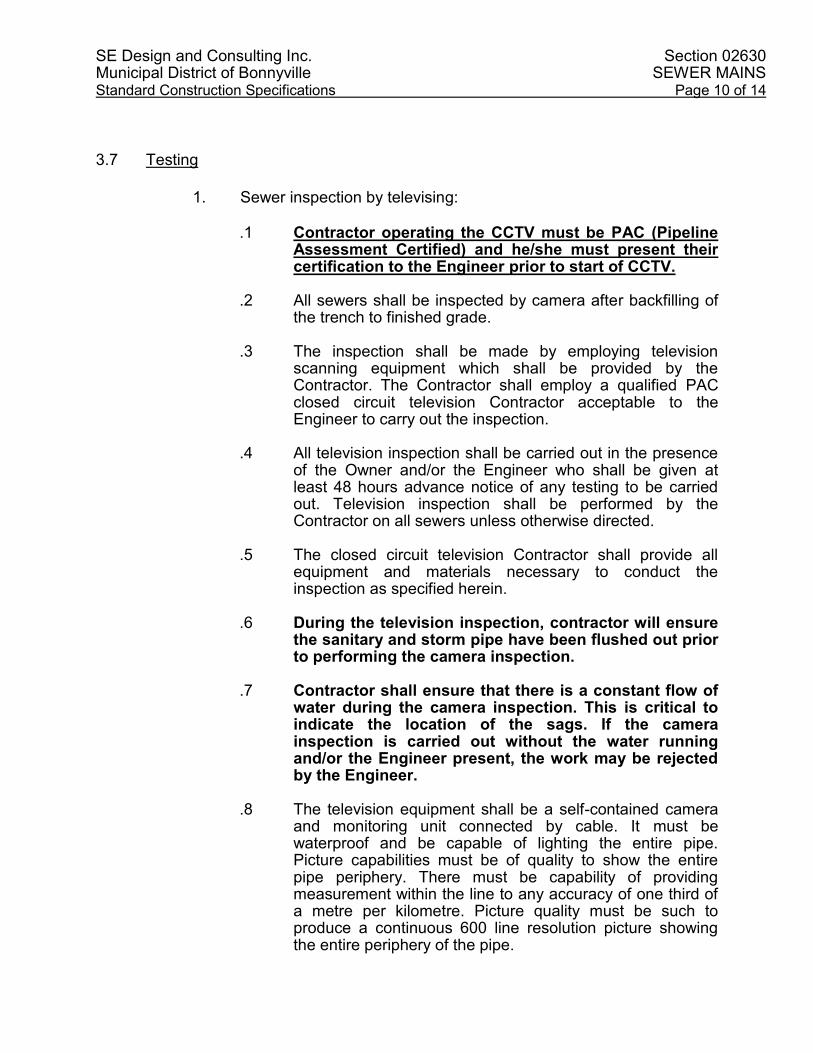
SE Design and Consulting Inc. Section 02630 Municipal District of Bonnyville SEWER MAINS Standard Construction Specifications Page 10 of 14
3.7 Testing
1. Sewer inspection by televising:
.1 Contractor operating the CCTV must be PAC (Pipeline
Assessment Certified) and he/she must present their certification to the Engineer prior to start of CCTV.
.2 All sewers shall be inspected by camera after backfilling of
the trench to finished grade. .3 The inspection shall be made by employing television
scanning equipment which shall be provided by the Contractor. The Contractor shall employ a qualified PAC closed circuit television Contractor acceptable to the Engineer to carry out the inspection.
.4 All television inspection shall be carried out in the presence
of the Owner and/or the Engineer who shall be given at least 48 hours advance notice of any testing to be carried out. Television inspection shall be performed by the Contractor on all sewers unless otherwise directed.
.5 The closed circuit television Contractor shall provide all
equipment and materials necessary to conduct the inspection as specified herein.
.6 During the television inspection, contractor will ensure
the sanitary and storm pipe have been flushed out prior to performing the camera inspection.
.7 Contractor shall ensure that there is a constant flow of
water during the camera inspection. This is critical to indicate the location of the sags. If the camera inspection is carried out without the water running and/or the Engineer present, the work may be rejected by the Engineer.
.8 The television equipment shall be a self-contained camera
and monitoring unit connected by cable. It must be waterproof and be capable of lighting the entire pipe. Picture capabilities must be of quality to show the entire pipe periphery. There must be capability of providing measurement within the line to any accuracy of one third of a metre per kilometre. Picture quality must be such to produce a continuous 600 line resolution picture showing the entire periphery of the pipe.

SE Design and Consulting Inc. Section 02630 Municipal District of Bonnyville SEWER MAINS Standard Construction Specifications Page 11 of 14
.9 The following capabilities and items must be available.
.1 A direct voice communication.
.2 A camera towing service.
.3 Self-contained electrical power.
.4 Proper safety equipment to protect employees and the general public.
.10 The cameras rate of progress shall be uniform during
inspection and shall not exceed 6 rn/mm.
.1 A television log shall be maintained during the inspection showing location of leak, fault, open joint, break, crack, collapse, settlement, obstruction, infiltration, or any other defect affecting the overall performance of the sewer line. The location of the defect shall be referenced from the manhole.
.2 A separate log shall be kept of service connections
with comments of condition. .3 Photographs shall be taken as directed or at the
discretion of the television scanning operator. A minimum of one photo per manhole reach is required plus one of every deficiency.
.4 Manhole identity shall be noted clearly as indicated on
the drawings.
.11 A final typewritten report with corresponding photograph secured properly and referenced to the text along with a copy of the video tape shall be submitted to the Engineer within two weeks after completion of inspection.
.12 The Contractor shall be responsible for all works performed
by the subcontractor, for traffic control and any other related work incidental to the completion of television inspection.
.2 Exfiltration test:
.1 If required by the Engineer, the Contractor shall conduct an exfiltration test.
.2 Fill test section with water in such a manner as to allow
displacement of air in line. Maintain under nominal head for 24 hours to ensure absorption in pipe wall is complete before test measurements are commenced.

SE Design and Consulting Inc. Section 02630 Municipal District of Bonnyville SEWER MAINS Standard Construction Specifications Page 12 of 14
.3 Immediately prior to test period add water to pipeline until
there is a head of 1.0 m over interior crown of pipe measured at highest point of test section or water in manhole is 1.0 m above static groundwater level, whichever is greater.
.4 Duration of exfiltration test shall be two hours. .5 Water loss at end of test period shall not exceed maximum
allowable exfiltration over any section of pipe between manholes.
.3 Infiltration test:
.1 If required by the Engineer, the Contractor shall conduct an infiltration test.
.2 Conduct infiltration test in lieu of exfiltration test where static
groundwater level is 750 mm or more above top of pipe measured at highest point in line to be used.
.3 Do not interpolate a head greater than 750 mm to obtain an
increase in allowable infiltration rate. .4 Install a watertight plug at upstream end of pipeline test
section. .5 Discontinue pumping operations for at least 72 hours before
test measurements are to commence, and during this time keep thoroughly wet at least one third of pipe invert perimeter.
.6 Prevent damage to pipe and bedding material due to
flotation and erosion. .7 Place a 900 V-notch weir, or other approved measuring
device in invert of sewer at each manhole. .8 Measure rate of flow over a minimum of 1 hour, with
recorded flow for each 5 minute interval.
.4 Infiltration and exfiltration shall not exceed following limits in litres per hour per 100 metres of pipe, including service connections:

SE Design and Consulting Inc. Section 02630 Municipal District of Bonnyville SEWER MAINS Standard Construction Specifications Page 13 of 14
Nominal Pipe Diameter in mm PVC Pipe
PVC Pipe Concrete Pipe
10 3.88 25.5
12 4.62 30.0
15 5.51 34.0
20 7.45 41.5
250 9.39 49.5
30 11.33 56.5
35 13.27 63.5
40 14.91 70.0
45 16.84 76.0
50 18.78 81.5
550 20.72 87.0
600 22.80 92.5
700 26.53 102.0
800 30.11 110.5
900 33.69 118.0
1,000 37.56 124.5
1,100 41.29 130.0
1,200 45.01 135.0
3.8 Acceptance
.1 The location of all deficient work will be recorded and the
Contractor will be required to repair, relay, restore or otherwise make good, to the satisfaction of the Engineer and Owner any deficient work including the repair of alignment problems, cracked or broken pipe, deformed pipe, leaks or any other faults not conforming with these specifications or the pipe manufacturers which the television inspection revealed.
.2 Tolerance of Sags in PVC Sanitary/Storm Pipe:
Pipe Diameter (mm)
Maximum Allowable Depth (D) of Sag
(mm)
Maximum Allowable Length (L) of Sag
(m)
Minimum Allowable Distance (X)
Between Sags (m)
100 10 1.5 5
150 10 1.5 5
200 20 2.0 10
250 20 2.5 20
300 and Larger 30 3.0 25

SE Design and Consulting Inc. Section 02630 Municipal District of Bonnyville SEWER MAINS Standard Construction Specifications Page 14 of 14
Any sags or ponding of water along the pipe will be repaired by excavation of the pipe, realigning and compacting the subgrade or relaying the non-conforming section of pipe if necessary. Any defects in the pipe or construction method revealed shall be corrected and CCTV for Engineers review, approval, and acceptance. All costs associated with the retesting and the correction of defects shall be the responsibility of the contractor.
.3 After the deficiencies are repaired and corrected and before final
acceptance, the Owner reserves the right to have the faulty areas re-inspected at the Contractor’s expense.
END OF SECTION

SE Design and Consulting Inc. Section 02721 Municipal District of Bonnyville GRANULAR BASE COURSE Standard Construction Specifications Page 1 of 4
1.0 GENERAL
1.1 Aggregate Supply
.1 To ensure product consistency, all aggregate material to be provided from the same source unless otherwise approved by the Engineer.
1.1 Samples
.1 At least 2 weeks prior to commencing work, inform of proposed source of granular materials.
.2 The Contractor shall provide a sieve analysis of the material for review.
1.2 Submissions
.1 Granular base course shall be submitted before being used.
.2 Preliminary review of the material as represented in the test results shall not constitute general acceptance of all material in the deposit or source of supply. Materials may be considered unsuitable even though particle sizes are within the limits of the gradation sizes required, if particle shapes are thin or elongated or any other characteristic precludes satisfactory compaction or if the material fails to provide a roadway suitable for traffic. Rejected material will not be paid for. The Engineer has the right to request additional testing if there are any concerns with the proposed aggregate.
1.3 Measurement for Payment
.1 Granular base course will be measured for payment as indicated on the tender form. Payment shall be compensation for supplying, loading, hauling, placing, remixing if segregation has occurred, compacting, moisture conditioning, shaping the material and provision of a sieve analysis.
2.0 PRODUCTS
2.1 Granular Base Course
.1 Material for the granular base course shall consist of sound, hard, durable crushed rock or crushed gravel and shall not contain organic or soft, thin, elongated, or laminated materials, materials that break up when alternately frozen and thawed or wetted and dried, or other deleterious materials. When compacted near the optimum moisture content to not less than 100% of the maximum dry density corrected for the stone content as determined by ASTM D698, the material shall have a minimum bearing ratio as defined by ASTM D1 883 of fifty-five percent (55%).

SE Design and Consulting Inc. Section 02721 Municipal District of Bonnyville GRANULAR BASE COURSE Standard Construction Specifications Page 2 of 4
.2 Granular base course shall meet the following gradation when tested
to ASTM Cl 36 and ASTM C11 7, and give a smooth curve without sharp breaks when plotted on a semi-log grading chart
Level Size (10-6 m)
Percent Passing (by weight)
25,000 100
20,000 82-97
16,000 70-94
10,000 52-79
5,000 35-64
1,250 18-43
630 12-34
315 8-26
160 5-18
80 2-10
.3 At least 60 percent by weight of material retained on the 5,000 sieve shall have two or more fractured faces.
.4 The liquid limit shall not exceed 25 and the plasticity index shall not
exceed 6 for the portion of material passing the 400 sieve.
3.0 EXECUTION
3.1 Placing
.1 The base material shall not be placed until the underlying course has been accepted. The granular material shall be placed in uniform layers not exceeding 150 mm in thickness before compaction. The material shall be placed by mechanical spreaders or deposited in windrows and leveled with suitable equipment.
3.2 Compaction
.1 Each layer of granular base course shall be compacted near the optimum moisture content to not less than 100% of the maximum dry density corrected for the stone content as determined by ASTM D698 Method A for the material used.
.2 During compaction, the moisture content shall be maintained at the
optimum moisture content as determined by ASTM D698. If the moisture content exceeds the optimum moisture content the material shall be aerated by mechanical means until the material has dried sufficiently to reach the optimum moisture content. Water shall be added if the moisture content is below optimum.

SE Design and Consulting Inc. Section 02721 Municipal District of Bonnyville GRANULAR BASE COURSE Standard Construction Specifications Page 3 of 4
3.3 Testing Compaction and Quality Control
.1 Compaction results shall be based on a minimum of one density test per 1,500 square metres of road. Additional tests may be called for by the Engineer as deemed necessary.
.2 Field density tests shall conform to ASTM D1556, ASTM D2167, or
ASTM D2922 for comparison with a maximum density determined according to ASTM D698 Method A.
.3 Areas which are not satisfactory to the Engineer shall be reworked and
retested at the Contractors expense. .4 The Contractor shall supply a Loaded Water Truck for the granular
base proof roll test. This test will be undertaken when the compaction of the granular base has been completed, and shall be under the direction and in the presence of the Engineer.
.5 Under no circumstances shall the Contractor cover the granular base
with asphalt base course, curb and gutter, or monolithic curb, gutter and sidewalk until all density test results and the granular base proof roll test performed in the presence of the Engineer are approved by the Engineer.
.6 Compaction density testing may be waived by the Engineer upon
satisfaction of the construction operations and results of the proof roll test.
.7 The compacted lift thickness of a granular course shall not exceed
150mm, or as directed by the Engineer. The required density of granular base courses is shown in the following table:
Compacted Granular Base Course
Required Percentage of Maximum Density
Under roads, curb and gutter 100%
Under commercial or alley crossings 100%
Under asphalt or concrete walk, transit pads 97%
Under walk portion of monolithic walk 97%
Under curb ramps 97%
Under private crossings 97%
Under median or island strips 97%
As granular road 100%
As granular walkways 97%

SE Design and Consulting Inc. Section 02721 Municipal District of Bonnyville GRANULAR BASE COURSE Standard Construction Specifications Page 4 of 4
3.4 Shaping and Finishing
.1 The finished surface of the granular base course shall conform to approved grades and shall meet the Field Quality control standard.
3.5 Inspection
.1 Before acceptance, the granular base course surface shall be true to cross-section and grade, and shall conform to the density and bearing ratio requirements specified.
.2 Field density and moisture content tests will be made by the Engineer
to ensure that the material is satisfactory. Material not meeting the specification requirements will not be approved and shall be removed and replaced at the contractor’s expense.
3.6 Field Quality Control
Check finished surface of granular base to ensure that it meets the following tolerances: .1 Surface Tolerance: 15mm maximum variation under 3m straightedge .2 Grade Tolerance: 6mm maximum variation above designated
elevation and 15mm maximum variation below designated elevation When tolerance Exceeded
.1 Trim high spots and refinish surface within tolerance
.2 Add approved aggregate to low areas, scarify, blend, respreads and re-compact to required density and refinish surface. Alternatively, compensate low areas with extra thickness of subsequent granular base course.
END OF SECTION

SE Design and Consulting Inc. Section 02741 Municipal District of Bonnyville HOT MIX ASPHALT PAVEMENT Standard Construction Specifications Page 1 of 12
1.0 GENERAL
1.1 Samples
.1 At least 2 weeks prior to commencing work, inform of proposed source
of aggregate materials. .2 The Contractor shall submit asphalt concrete mix design based on the
Marshall Method and trial mix test results for review at least 2 weeks prior to commencing work. The Contractor shall provide a sieve analysis of the aggregate material for review.
1.2 Submissions
.1 Asphalt concrete mix design and aggregate material shall be submitted
before being used. Aggregate shall be tested for detrimental matter in coarse aggregate.
.2 Preliminary review of the aggregate as represented by the samples
shall not constitute general acceptance of all material in the deposit or source of supply. Materials may be considered unsuitable even though particle sizes are within the limits of the gradation sizes required, if particle shapes are thin or elongated or any other characteristic precludes satisfactory compaction or if the material fails to provide a pavement suitable for traffic. Rejected material will not be paid for. The Engineer has the right to request additional testing if there are any concerns with the proposed aggregate mix design.
1.3 Measurement for Payment
.1 Hot mix asphalt pavement will be measured as indicated on the tender
form for the full length and width as constructed at the specified depth indicated. Payment shall be compensation in full for furnishing, mixing, transporting, placing and rolling, provision of a sieve analysis and asphalt concrete mix design, and for all other labor and materials required to complete the work. Payment for asphalt pavement shall be subject to the penalties outlined in Section 3.13 for deficient pavement. Asphalt concrete required as a leveling course in addition to the specified depth will be measured as indicated on the tender form for the full length and width as constructed at the specified depth indicated.

SE Design and Consulting Inc. Section 02741 Municipal District of Bonnyville HOT MIX ASPHALT PAVEMENT Standard Construction Specifications Page 2 of 12
1.4 Definitions
.1 Overlay: Paving over an existing pavement for rehabilitation purposes and not as part of staged paving.
.2 Staged Paving: Paving where a lift or lifts that form part of the total
pavement structure are deferred to a future date
2.0 PRODUCTS
2.1 Mix
.1 Required minimum Marshall Density shall be as specified herein.
2.2 Aggregate
.1 Aggregate shall consist of hard, durable, uniformly graded crushed
gravel and shall not contain organic or soft materials that break up when alternately frozen and thawed or wetted and dried, nor other deleterious materials.
.2 Aggregate shall meet the following gradation when tested to ASTM C1
36 and ASTM C117, and give a smooth curve without sharp breaks when plotted on semi-log grading chart:
Sieve Size
(10-6 m) Percent Passing
(by weight)
25,000 --
20,000 --
12,500 100
10,000 87-95
5,000 65-80
2,000 42-64
800 27-47
400 19-37
160 9-20
80 4-8
a) The Liquid Limit shall not exceed 25 and the Plasticity Index shall not exceed 6 for the portion of material passing the 400 sieve.
b) Los Angeles Abrasion Maximum % loss by weight: 40%
SE Design and Consulting Inc. Section 02741 Municipal District of Bonnyville HOT MIX ASPHALT PAVEMENT Standard Construction Specifications Page 3 of 12
c) Crushed Fragments: The minimum percentage, by mass retained down to the 4.75 mm sieve of fragments having at least 2 freshly fractured faces shall be 75% minimum crushed face count:
d) Maximum of 3.0% total deleterious matter by total mass of
combined aggregate.
.3 Should the grading of the mineral aggregates supplied to the plant not meet the gradation above, mineral filler shall be added in the weight hopper of the asphalt plant in such quantities as will be required to meet the specifications.
2.3 Mineral Filler
.1 Mineral filler shall consist of Portland Cement, Pozzolan, commercially
ground stone dust or other mineral dust approved by the Engineer. Mineral filler shall have a Plasticity Index of Zero and when tested by means of laboratory sieves, it shall meet the following gradation:
Sieve Size (10-6 m)
Percent Passing (by weight)
400 100
160 not less than 90
80 not less than 70
45 not less than 62
.2 Mineral filler to be dry and free flowing when added to aggregate.
2.4 Asphaltic Binder
The asphaltic binder shall be uniform in character, shall not foam when heated to 175°C and shall meet the following requirements:
.1 Designation A/C 150/200 .2 Penetration (ASTM D5) under 100 g for 5 sec. at 25°C……150 to 200 .3 Flash Point (ASTM D92) filled or unfilled greater than……………190°C .4 Ductility (ASTM 0113) strain rate of 5 cm.sec. at 25°C greater
than…..1 00(+) cm
.5 Solubility in CC1 4 [unfilled] 99.0[+]%
.6 Kinematic Viscosity in Centistokes at 135°C…………………….150(+) .7 Thin Film Oven Test Penetration under 100 g for 5 sec. at 25°C
.45(+)%

SE Design and Consulting Inc. Section 02741 Municipal District of Bonnyville HOT MIX ASPHALT PAVEMENT Standard Construction Specifications Page 4 of 12
2.5 Mix Design
.1 From the aggregate and asphalt cement samples, the testing laboratory shall prepare a design mix to produce the following criteria:
Max. Aggregate Size, mm
12.5
No. of Blows 75 Minimum Stability, N 8,000 Minimum Retained Stability,_% 70
Flow (mm) 2.0 to 3.5
.2 The Marshall Stability Value and the Flow Index shall be tested in
accordance with the current issue of ASTM D1559 for Resistance to Plastic Flows of Bituminous Mixtures.
.3 The Percentage Voids and Percentage Aggregate Voids Filled with
Asphalt shall be determined according to the Marshall Method of Mix Design for Hot Mix Asphalt Paving, as set out in the latest edition of the Asphalt Institute Manual Series.
3.0 EXECUTION
3.1 Preparation
.1 Patch and correct depressions and other irregularities before beginning paving operations. Prior to laying mix, clean surfaces of loose and foreign material and apply primer coat or tack coat in accordance with Section 02745.
.2 Where the asphaltic surface course is placed in two lifts, the surface of the first lift shall first be thoroughly cleaned of dirt or other deleterious material by sweeping with a power broom supplemented by hand brooming and scraping where necessary. A tack coat shall then be applied, where required, by means of an approved pressure distributor. No levelling course or surface course mixtures shall be placed until the tack coat is thoroughly set.
.3 If levelling is required prior to placement of 2nd lift, it will be at contractor’s expense.
.4 Where the asphaltic surface course is to be placed in 2 lifts, the first lift shall be placed , finished and compacted for the full width as shown on the drawings, prior to commencing on the second lift.
.5 In placing the second lift, the individual mixture spreads shall be aligned in a manner such that the longitudinal joints in each layer will not coincide.
.6 Contractor to note on the schedule of quantities if the second lift is to be installed during the following year (2nd year). If the year of installation for the

SE Design and Consulting Inc. Section 02741 Municipal District of Bonnyville HOT MIX ASPHALT PAVEMENT Standard Construction Specifications Page 5 of 12
second lift is not indicated on the tender form, then the second lift is to be installed during the first year of construction.
3.2 Mix Tolerances .1 All mixture furnished shall conform to the job mix formula within the range of
tolerance specified:
.1 Aggregate Material Passing Percent by Weight 5,000 um Sieve ±6 800 um Sieve ±4 80 um Sieve ±1.5 .2 The amount of bituminous material designated for the job mix
shall be maintained within the tolerance of 0.3 percentage points.
.3 The temperature of mixing asphaltic mixtures shall not vary
from those specified in the job mix formula by more than 9°C.
.4 Air voids in mix: Air Voids 3.5 to 4.0%.
.5 Film thickness in mix: Minimum Film Thickness of 6.0um.
.6 Voids filled in mix: Voids Filled Limits 65 to 75%.
3.3 Mixing Plant
.1 The mixing plant and auxiliary equipment shall be such as to combine, dry
and heat the mineral aggregate, heat the asphalt and accurately proportion the asphalt and aggregate to produce a uniform mixture in accordance with these specifications.
3.4 Transportation of Mix
.1 The mixture shall be transported from the mixing plant to the work in vehicles with tight metal bottoms previously cleaned of all foreign materials. The vehicle shall be suitably insulated and each load shall be covered with canvas or other suitable material of sufficient size to protect it from weather conditions. The inside surface of all vehicles may be lightly lubricated with a thin oil or soap solution prior to loading but excess lubricating will not be permitted.
.2 Any accumulation of asphaltic material which was collected in the box shall
be thoroughly cleaned before loading with hot mix. .3 Trucks shall be maintained perfectly clean of mud or any substance which
could contaminate the working area.

SE Design and Consulting Inc. Section 02741 Municipal District of Bonnyville HOT MIX ASPHALT PAVEMENT Standard Construction Specifications Page 6 of 12
3.5 Equipment
.1 Payers:
.1 Mechanical grade controlled self-powered payers capable of spreading mix within specified tolerances, true to line, grade and crown indicated.
.2 Roller:
.1 The rollers used for compaction shall be self-propelled steel-
wheeled or rubber-tired rollers, providing at least 35 Newton’s per millimeter width of tread. The roller shall be in good condition without backlash when reversed and shall be operated by competent roller men. The wheels shall be kept properly moistened, but excess water or oil will not be permitted.
.3 Hand Tools:
.1 Lutes or rakes with covered teeth for spreading and finishing operations.
3.6 Placing
.1 Obtain approval of base and existing surface and tack coat and prime coat prior to placing asphalt. Asphaltic concrete shall be constructed in layers to obtain the following minimum and maximum compacted thickness:
Minimum (mm) Maximum (mm)
35 80
.2 Place asphalt concrete to thicknesses, grades and lines indicated or directed. .3 Placing Conditions:
.1 Place asphalt mixtures only when air temperature is above
2°C. .2 When temperature of surface on which material is to be placed
falls below 10°C, provide extra rollers as necessary to obtain required compaction before cooling.

SE Design and Consulting Inc. Section 02741 Municipal District of Bonnyville HOT MIX ASPHALT PAVEMENT Standard Construction Specifications Page 7 of 12
.3 Do not place hot mix asphalt when pools of standing water exist on surface to be paved, during rain, or when surface is damp.
.4 Mixtures shall be spread at temperatures which, when
measured in the hopper of the spreader, are not lower than 125°C or higher than 150°C.
.5 In small areas where the use of mechanical finishing equipment is not
practical, the mix may be spread and finished by hand, if so directed. The material shall be distributed uniformly to avoid segregation of the coarse and fine aggregates. Broadcasting of material shall not be permitted. During the spreading operation, all material shall be thoroughly loosened and uniformly distributed by lutes or rakes. Material that has formed into lumps and does not break down readily shall be rejected.
3.7 Rolling and Compaction
.1 Before rolling is started, the surface shall be checked, inequalities in depth
adjusted and fat spots or sandy accumulations replaced and irregularities in alignment or grade along the outside edge shall be corrected.
.2 The rollers must be kept in continuous operation as nearly as practicable and
all parts of the pavement shall receive substantially the same compaction. Rolling shall be done at a maximum speed of 5 km per hour.
.3 At least one roller shall be used for every 40 tonnes of asphaltic concrete laid
per hour. Rolling shall start as soon as the pavement will bear the roller without checking or undue displacement, working from the low part or edge to the high part or edge continuously until no roller marks are left in the finished surface and no further compaction is possible. Where width permits the pavement shall be rolled diagonally in two directions. At all curbs, manholes and other appurtenances, and at all locations not accessible to the rollers, hand tampers shall be used to produce the same density as provided by the roller. Where the asphaltic concrete is laid in more than one lift, each lift shall be so compacted.
.4 Required Density: Each mat of hot mix placed shall be compacted to the
following minimum density (% of Marshall density) for the type of paving.
Minimum Density Type of Paving
98% New paving and all stages in staged paving except 2nd stage residential < 40 mm.
96% Second stage residential mat 40 mm thick or less.
97% Lane paving. 97% Overlay more than 40 mm thick. 96% Overlay 40 mm thick or less.

SE Design and Consulting Inc. Section 02741 Municipal District of Bonnyville HOT MIX ASPHALT PAVEMENT Standard Construction Specifications Page 8 of 12
3.8 Joints
.1 The mixture shall be laid so that all longitudinal joints are made while the first
mat of the two being laid is still hot. .2 A narrow strip along the edge of a mat which is joined with another asphalt
mat shall be left without rolling until the adjoining mat has been placed against it. The joint which is formed shall be rolled immediately after the adjacent mat has been placed to ensure a bonding of the material while the asphalt is still hot.
.3 Transverse joints shall be carefully constructed and thoroughly compacted to
provide a smooth-riding surface. Joints shall be straight-edged to assure smoothness and true alignment and shall be offset at least one meter from joints of adjacent mats. The vertical face shall be treated with freshly laid mixture raked against it, tamped with hot tampers and rolled. Heat shall be used as necessary to ensure a proper bond.
.4 All concrete or metal structures such as gutters, manholes, etc. shall be
painted with an approved bituminous material prior to placing the plant mix.
3.9 Butt Joints
.1 Butt joint, a vertical face is constructed by hand across the width being paved. This operation consists of raking, shoveling, and then removing the mix that is located downstream of the selected joint location.
.2 It is necessary for the rollers to compact the mix immediately adjacent to the
joint. For this to be done properly, runoff boards must be placed next to the joint. The thickness of the boards should be approximately equal to the compacted thickness of the layer being placed. In addition, the boards must be wide and long enough to support the full size of a roller. The compaction equipment passes over the mix at the joint and onto the boards before the rolling direction is reversed. This practice ensures that the transverse joint receives the same degree of compaction as the rest of the mix in the pavement layer.
.3 After materials have been removed and discarded, the area adjacent to the
joint should be cleaned of all dust and other loose particles. The exposed edge should be lightly tacked with an acceptable tack coat.

SE Design and Consulting Inc. Section 02741 Municipal District of Bonnyville HOT MIX ASPHALT PAVEMENT Standard Construction Specifications Page 9 of 12
3.10 Finish
.1 The finished pavement shall be true to the required profile and cross-section.
Tests of pavement profile and thickness shall be made after the first layer of asphalt has been placed, and depressions or bumps in excess of 5 mm shall be corrected. The allowable tolerance for finished pavement shall be ±5 mm, and the surface shall show no depressions or bumps exceeding 3 mm under a straight-edge 3 m long placed parallel to the road centerline.
.2 Finished surface shall have a tightly knit texture free of visible signs of poor
workmanship such as, but not limited to:
.1 Segregation; .2 Areas exhibiting excess or insufficient asphalt; .3 Improper matching of longitudinal and transverse joints; .4 Roller marks, cracking, or tearing;
If surface and grade tolerances are exceeded, or if surface texture is not met,
grind down and resurface defective areas as required.
3.11 Defective Work
.1 Correct irregularities which develop before completion of rolling by loosening
surface mix and removing or adding material as required. If irregularities or defects remain after final compaction, remove surface course promptly and lay new material to form a true and even surface and compact immediately to specified density.
.2 Repair areas showing checking or hairline cracking.
3.12 Testing and Inspection
.1 The Contractor or his representative shall retain core samples from the
completed pavement, from which depth of pavement and density tests shall be made.
.2 One core shall be taken for approximately every 1,000 m2 of asphalt or at
least once each day during placing operations. The following tests shall be carried out:
.1 Marshall stability (test for resistance of plastic flow of
bituminous mixtures) using Marshall Apparatus as per ASTM 01559.

SE Design and Consulting Inc. Section 02741 Municipal District of Bonnyville HOT MIX ASPHALT PAVEMENT Standard Construction Specifications Page 10 of 12
.2 Sieve analysis of extracted aggregates in accordance with
ASTM C136 and entire washed sample in accordance with ASTM C1 17.
.3 Bulk specific gravity of compacted mixtures in accordance with
ASTM D2726. .4 Bitumen content of paving mixtures in accordance with ASTM
D2172. .5 Percent voids in the mineral aggregates (VMA) is to be
calculated on the basis of ASTM D2726 Bulk Specific Gravity of the aggregate.
.6 Air voids in compacted mix in accordance with ASTM 03203.
.3 The Contractor shall repair all test holes with fresh, hot mix asphaltic concrete
mixture, and thoroughly compact it to the required density with no additional compensation.
3.13 Penalties
.1 Thickness:
.1 If the average core thickness is deficient, that area of asphalt
pavement will be assessed a pay factor according to the following table and be applied to the price of the quantity of hot-mix asphalt in that mat area.
Thickness Deficiency (%) Pay factor (%) 10.0 100 11.0 97.0 12.0 93.7 13.0 90.0 14.0 85.5 15.0 80.5 16.0 75 17.0 68 18.0 60 19.0 50 19.0 and Over Mill and resurface
.2 Density:
.1 The cores will also be used to determine density. If any test
fails to meet the density specified, two more cores shall be taken in the area, and the average density of the three cores shall represent the area. If the densities are less than

SE Design and Consulting Inc. Section 02741 Municipal District of Bonnyville HOT MIX ASPHALT PAVEMENT Standard Construction Specifications Page 11 of 12
specified, the Contract Unit Price shall be adjusted as follows:
ASPHALT DENSITY PAY FACTORS
98% Required 97% Required 96% Required
Actual Density %
Pay Factor %
Actual Density %
Pay Factor %
Actual Density %
Pay Factor %
98.0 100.0 97.0 100.0 96.0 100.0
97,9 99.9 96.9 99.9 95.9 99.7
97.8 99.8 96.8 99.7 95.8 99.3
97.7 99.6 96.7 99.4 95.7 98.9
97.6 99.4 96.6 99.1 95.6 98.4
97.5 99.1 96.5 98.7 95.5 97.8
97.4 98.7 96.4 98.2 95.4 97.1
97.3 98.3 96.3 97.7 95.3 96.4
97.2 97.8 96.2 97.1 95.2 95.6
97.1 97.2 96.1 96.3 95.1 94.6
97.0 96.5 96.0 95.5 95.0 93.4
96.9 95.8 95.9 94.6 94.9 92.2
96.8 95.0 95.8 93.6 94.8 90.7
96.7 94.2 95.7 92.5 94.7 89.1
96.6 93.3 95.6 91.3 94.6 87.3
96.5 92.3 95.5 89.9 94.5 85.1
96.4 91.1 95.4 88.4 94.4 82.6
96.3 89.8 95.3 86.7 94.3 79.5
96.2 88.5 95.2 84.8 94.2 75.5
96.1 87.1 95.1 82.7 94.1 69.7
96.0 85.5 95.0 80.3 94.0 60.0
95.9 83.8 94.9 77.6 Under 94.0 Reject
95.8 82.0 94.8 74.3
95.7 80.0 94.7 70.6
95.6 77.7 94.6 66.0
95.5 75.4 94.5 60.0
95.4 73.0 Under 94.5 Reject
95.3 70.3
95.2 67.2
95.1 63.7
95.0 60.0
Under 95.0 Reject Actual Density = % of Marshall density. Pay Factor = % of contract price.

SE Design and Consulting Inc. Section 02741 Municipal District of Bonnyville HOT MIX ASPHALT PAVEMENT Standard Construction Specifications Page 12 of 12
3.14 Acceptance
.1 Locations shall be cleared of all excess material resulting from the paving operation and any damage caused by the Contractor shall be repaired to the Engineer’s satisfaction within 3 days of the date of completion of the street or lane. Failure to cleanup or repair damage may result in other crews undertaking this work without notice to the Contractor and deducting the costs from money due to the Contractor.
.2 No traffic shall be allowed on the finished surface until it has cooled to
atmospheric temperature.
END OF SECTION

SE Design and Consulting Inc. Section 02745
Municipal District of Bonnyville PRIME AND TACK COATS
Standard Construction Specifications Page 1 of 4
1.0 GENERAL
1.1 Definitions
.1 Prime Coat:
.1 Prime coat shall be the application of bituminous material to previously prepared subgrade or granular base course, preparatory to placing bituminous surfacing materials or asphaltic concrete base course. An application of a liquid asphalt material on a prepared surface at locations shown on the Drawings or designated by the Consultant.
.2 Tack Coat:
.1 Tack coat shall be the application of bituminous material to a previously constructed paving surface of any type in preparation of placing bituminous surfacing materials. An application of a liquid asphalt to ensure a bond between the surface being paved and the next course.
1.2 Measurement for Payment
.1 Measurement for prime and tack coats will be as indicated on the
tender form at the rate of application specified in each case. Payment shall include the supply of materials, preparation of the surface, brooming or sweeping the surface, application, sand blotting, including supply of sand, maintaining the treated surface and the supply of all tools and incidentals to complete the work.
2.0 PRODUCTS
2.1 Prime Coat
.1 The bituminous material for priming the base course shall be liquid
asphalt. The contractor’s choice of SEP-1, SEP-2 or SS-1 for application through August 31 each season. The Contractor’s choice of MC-30, SEP-1, SEP-2 or SS-1 for application after August 31 each season. Sand used for the blotting of excess asphalt due to prime shall be supplied by the Contractor.

SE Design and Consulting Inc. Section 02745
Municipal District of Bonnyville PRIME AND TACK COATS
Standard Construction Specifications Page 2 of 4
2.2 Tack Coat
.1 The bituminous material for tacking the existing asphalt surface shall be liquid asphalt. SS-1 or MS-1 for application throughout the construction season. As well, the Contractor has the option of suing RC-30 or RC-70 for application after August 31 each season.
2.3 Sand Blotter
.1 The materials for sand cover shall consist of clean granular mineral
material all of which shall pass a 5,000 sieve.
3.0 EXECUTION
3.1 Equipment
.1 Cleaning equipment shall consist of power brooms, flushers, and
whatever hand scrapers may be necessary to remove all foreign material.
.2 The pressure distributor used for applying asphaltic material shall
distribute the asphaltic material at an even temperature, uniformly on variable widths of surface up to 5 metres. Uniform spray without atomization shall be determined and controlled from 0.2 to 5.4 litres per minute (Urn) with uniform pressure, and with an allowable variation from any specified rate not exceeding 0.1 L/m.
.3 Suitable means for accurately indicating the temperature of the
asphaltic material shall be provided at all times. The thermometer well shall be placed so as not to be in contact with a heating tube.
.4 If provided with heating attachments the distributor shall be so
equipped and operated that the asphaltic material shall be circulated or agitated throughout the entire heating process.

SE Design and Consulting Inc. Section 02745
Municipal District of Bonnyville PRIME AND TACK COATS
Standard Construction Specifications Page 3 of 4 3.2 Preparation
.1 Immediately prior to applying the asphalt primer or tack coat, the surface shall be brought to uniform cross-section by patching all depressions and defective areas using an approved patching material and by removing all bumps and irregularities.
.2 All loose and foreign material shall be removed by light sweeping.
3.3 Application
.1 Obtain approval of existing surface before applying asphalt prime or
tack coats. Clean surface as required. .2 Upon the prepared surface the asphalt shall be applied uniformly at a
rate of from 0.50 to 1.50 litres/square metre (l/m2) for asphalt primer, and at a rate of from 0.25 to 0.90 L/m2 for tack coat. The asphalt primer or tack coat shall be applied only when the surface is dry or slightly damp, or only when the air temperature in the shade is above 10°C.
.3 The application temperature of the asphalt primer or tack coat shall be
as follows:
.1 Rapid Curing Asphalt: RC-30 51 -68°C RC-70 74 - 88°C RC-250 100-110°C .2 Medium Curing Asphalt: MC-30 51 - 68°C MC-70 74 - 88°C MC-250
100-110°C .3 Emulsified Asphalt: SS-1 24-54°C SS-1H 24-54°C .4 Emulsified Asphalt Primer: 15- 50°C
.4 Coat contact surfaces of curbs, gutters, headers, manholes and like
structures with a thin uniform coat of asphalt material. Do not prime or tack surfaces that will be visible when paving is complete. Work adjacent to the roadway shall be completely protected from the application operation by a suitable covering. Any unnecessary splashing of the concrete shall be cleaned.

SE Design and Consulting Inc. Section 02745
Municipal District of Bonnyville PRIME AND TACK COATS
Standard Construction Specifications Page 4 of 4
.5 Do not apply asphalt coat when air temperature is less than 5°C or when rain is forecast within 2 hours.
.6 The Contractor shall maintain the primed surface until the surface course has been placed. Maintenance shall include spreading any additional sand and patching any breaks in the primed surface with additional asphaltic material.
.7 The asphalt primer should preferably be entirely absorbed by the base
course and therefore require no sand cover. If, however, the asphalt has not been completely absorbed 24 hours after application, just sufficient sand shall be spread over the surface to blot up excess asphalt and prevent it from being picked up by any traffic.
.8 Traffic shall not be permitted to travel on the tack coat until cured. The
Contractor shall use flagmen, if required, and signage to control traffic until the tack coat has cured.
.9 Traffic shall not be permitted to travel on the prime coat until 6 hours
after application or until it has cured. After this period of time, excess asphalt material remaining on the surface shall be blotted by sand before traffic is permitted to travel on the surface.
END OF SECTION

SE Design and Consulting Inc. Section 02770 Municipal District of Bonnyville CONCRETE Standard Construction Specification Page 1 of 10
1.0 GENERAL 1.1 Measurement for Payment
.1 Payment for concrete shall be full compensation forming, supplying and placing concrete and reinforcing steel, jointing, jointing materials, finishing, curing, stripping forms, backfilling, boulevard restoration with topsoil and seeding where required to match existing, and removal and replacement of existing street and traffic signs. Payment will as indicated on the tender form.
.2 Payment for shall be subject to the penalties outlined in Section
3.12 for deficient concrete. All basis of payment shall be on cylinder strength.
2.0 PRODUCTS 2.1 Cement
.1 All cement used shall be Portland Cement and shall conform to CSA standard CAN3A5 Type 50 sulphate resistant cement.
2.2 Aggregates
.1 Aggregates shall conform to CSA standard CAN3-A.23.1. 2.3 Water
.1 Water shall conform to CSA standard CAN3-A.23. 1. Water shall be clear, free from injurious amounts of oil, acid, alkali, organic matter, sediment, or other substances harmful to mixing and curing of concrete.
2.4 Air Entraining Mixture
.1 Air entraining mixture shall conform to CSA standard CAN3-A.266.1-M.
2.5 Reinforcing Steel
.1 Reinforcing steel shall conform to the following requirements:
.1 Welded steel wire fabric shall conform to CSA standard G30.5.
.2 Billet steel bars shall conform to CSA standard G30.12-M.

SE Design and Consulting Inc. Section 02770 Municipal District of Bonnyville CONCRETE Standard Construction Specification Page 2 of 10
2.6 Expansion Joint Filler
.1 Expansion joint filler shall be a non-extruding bituminous type and shall conform to ASTM D1751 for preformed expansion joint fillers.
2.7 Expansion Joint Sealer
.1 Joint sealer shall conform to CGSB standard specification for polyurethane sealing compound 1 9-GP-1 5 or ASTM standard specification for hot poured joint sealer D1190.
2.8 Membrane Curing Compound
.1 Curing compound shall be impervious resin based, liquid membrane—forming compound conforming to ASTM standard specification C309, Type 2, Class B with white pigmentation.
2.9 Concrete
.1 The concrete mix shall be designed as follows:
.1 Minimum 28 day compressive strength 30 MPa
.2 Slump not exceeding 150 mm
.3 Maximum aggregate size 20 mm
.4 Air entrainment 5.0% to 8.0% .2 Ready mixed concrete shall be mixed and transported in
accordance with ASTM C-94 for Ready Mixed Concrete. 2.10 Levelling Course
.1 Leveling course shall be medium to coarse graded sand meeting the following gradation when tested to ASTM C136 and ASTM C117, and give a smooth curve without sharp breaks when plotted on semi-log grading chart:
Sieve Size (10-6 m)
Percent Passing (by weight)
25,000 100
5,000 95-100
1,250 53-85
200 10-30
63 0-10 .2 The liquid limit shall not exceed 25 and the plasticity index shall not
exceed 6 for the portion of material passing the 400 sieve.

SE Design and Consulting Inc. Section 02770 Municipal District of Bonnyville CONCRETE Standard Construction Specification Page 3 of 10
3.0 EXECUTION 3.1 Grade Preparation
.1 The bed for the concrete shall be excavated and prepared to the lines, grades and cross-sections on the plans or directed. Unsuitable material shall be removed and disposed of. The subgrade shall be uniformly compacted to eliminate all soft and spongy areas to provide a firm base for all concrete work.
.2 A layer of compacted clean leveling course shall be used as a
foundation material under concrete. The base on which the concrete will rest shall be thoroughly wetted immediately prior to placing the concrete and must not be frozen, muddy or have areas of water pondage.
.3 The subgrade elevation -shall be finished to tolerances requiring 50
mm of leveling course materials on the subgrade. This material shall be compacted to 100% Standard Proctor Density.
3.2 Forms
.1 Forms shall be of steel or wood of sufficient strength to resist the pressure of wet concrete, and the supply shall be sufficient to permit their remaining in place not less than 12 hours after concrete has been placed. The use of bent, twisted, battered or worn-out forms will not be permitted. Forms shall be held securely by approved methods to prevent movement and bulging when the concrete is placed. Forms must be checked for alignment and elevation before concrete is poured, and shall be cleaned and oiled before each use.
3.3 Reinforcement
.1 Where required, reinforcement shall be secured in the location shown on the drawings and shall be free from mill scale, grease and rust immediately prior to placing concrete. Reinforcement shall be drilled and dowelled into existing concrete at all joints.
3.4 Placement
.1 The concrete shall be placed as soon as possible after mixing, but not later than one hour after mixing has begun. Retempered concrete shall not be used. The concrete shall be transported by methods which will prevent segregation and deposited on the subgrade to that as little handling as possible is required.

SE Design and Consulting Inc. Section 02770 Municipal District of Bonnyville CONCRETE Standard Construction Specification Page 4 of 10
.2 Concrete shall be placed continuously until a complete section between expansion joints has been poured.
.3 The concrete shall be thoroughly consolidated against and along
the faces of the forms. Hand spreading shall be done with shovels, not with rakes, in order that the concrete will not be segregated. Precautions should be taken to prevent overworking of the concrete.
3.5 Appurtenances
.1 Appurtenances shall be located, examined for deficiencies and staked by the Contractor prior to work beginning on a particular section and any deficiencies noted must be reported immediately. Upon completion of a block of work, the Contractor shall relocate these structures and inspect them. Any damage which may have occurred during the concreting operations and deficiencies not previously reported, shall be repaired at the Contractor’s expense.
3.6 Finishing
.1 Surfaces shall be struck off and screeded to the slope, cross-section and elevation shown on the drawings and as staked. The surface shall be consolidated and smoothed using a wood float. Light street trowelling shall be used followed by a uniform brush finish. After brushing and before the concrete has taken its initial set, surfaces shall be edged at all joints to prevent chipping of the concrete. No patching will be allowed.
3.7 Expansion and Contraction Joints
.1 Contraction joints shall be constructed at 3 metre intervals, and shall not be less than 50 mm deep. In the case of monolithic or separate sidewalks, an additional midway surface joint, 13 mm deep, shall be constructed in sidewalks and shall not extend through the curb and gutter.
3.8 Curing
.1 All concrete shall receive two applications of membrane curing compound. The first application is to be applied after the disappearance of the water sheen and the final finishing of the concrete. During hot, dry, windy days, the first application shall be applied immediately after final finishing and before all free water on the surface has evaporated. The second applications hall be made immediately at right angles to the first so that complete coverage on the surface is attained. Immediately after removal of the forms all exposed surfaces shall be thoroughly wetted with water and then sprayed with membrane curing compound. The membrane

SE Design and Consulting Inc. Section 02770 Municipal District of Bonnyville CONCRETE Standard Construction Specification Page 5 of 10
curing compound shall be applied in accordance with the manufacturer’s instructions.
3.9 Cold Weather Requirements
.1 When the temperature of the surrounding atmosphere is at, or below 4°C, the aggregate and the mixing water shall be heated. The aggregate and mixing water shall have a temperature of not less than 4°C and be entirely free of frozen materials. The aggregate shall not be heated to more than 60°C, and the concrete when deposited in the forms shall have a temperature of not less than 10°C nor more than 38°C. The concrete shall be maintained at a temperature of 10°C for not less than four days after placing.
3.10 Tolerances
.1 The finished surfaces of all concrete work shall be true to the required cross-section with a tolerance of plus or minus 6 mm from the required elevation and dimensions. Surface of curbs, gutters or sidewalks shall not show any depressions or bumps exceeding 3 mm under a straight edge 3 m long placed parallel to the curb or sidewalk. Concrete not meeting the requirements specified shall be removed to the nearest joint and replaced at the Contractor’s expense.
3.11 Field Tests
.1 Tests shall be made of the concrete to ensure that it meets these specifications. Testing shall be done to conform to the following standard specifications:
Test Current Issue of ASTM
Sampling of Fresh Concrete C172 Test for Slump of Concrete C143 Compression and Flexure Test C31 Compressive Strength of Molded Concrete Cylinders
C39
Measurement of Air Content C1 73 or C231
.2 Three concrete cylinders shall constitute one test and shall be
made from the same batch or load. They shall be stored undisturbed on site for 24 hours, covered with a plastic sheet to prevent loss of moisture. They shall then be delivered to an approved testing laboratory, and laboratory cured with one cylinder tested at seven days and the other two at twenty-eight days. A set of three cylinders shall be taken for every 100 m3 of concrete poured, or as directed.

SE Design and Consulting Inc. Section 02770 Municipal District of Bonnyville CONCRETE Standard Construction Specification Page 6 of 10
.3 When construction begins, the Engineer reserves the right to
request additional cylinders to be made in order to establish a concrete strength pattern as quickly as possible.
.4 The Contractor or his representative shall make the cylinders and
slump tests. 3.12 Penalties for Insufficient Strength
.1 Where there are variations from specified design strength, the following adjustments will be made based on the 28 day, laboratory cured cylinders.
.1 When concrete strength of any set exceeds 95% of design
strength, full payment for the work shall be made at the contract unit prices.
.2 When concrete strength of any set is greater than 80% but less than 95% of design strength, the price paid to the Contractor for the work represented by that set of cylinders shall be determined by the following formula:
2P(A-B) P- [ A ] Where: P = unit price A = specified strength B = average 28 day cylinder strength.
.3 If concrete strength of any set is less than 80% of design
strength, the work represented by that set of cylinders will be rejected.
.4 Where the average strength of all tests for the total work falls below design strength, but above 95% of design strength, that work not already having a price adjustment under the preceding clauses shall be subject to the following adjustment. The price paid by the Contractor shall be determined by the following formula:
2P(A-B)
P- [ A ]
Where: P = unit price A = specified strength B = average 28 day cylinder strength.

SE Design and Consulting Inc. Section 02770 Municipal District of Bonnyville CONCRETE Standard Construction Specification Page 7 of 10
3.13 Protection
.1 Keep all animals and pedestrians off the newly constructed concrete until completely set. The Contractor shall also be responsible for keeping all traffic off the work for a period of 5 days after the concrete has been finished.
3.14 Backfilling
.1 Backfill along the backs of concrete, to the top of the concrete, within seven days of the placing of the concrete. The backfill shall be mechanically tamped in maximum lifts of 150 mm to a minimum density of 95% Standard Proctor Density, to a distance 1.0 m from the back of the walk or curb.
3.15 Final Cleanup
.1 As the work progresses, clean up the site and all areas in which
work has been done shall be left in a neat and presentable condition. All gutters and street drainage ditches which have been blocked as a result of the Contractor’s trenching operation shall be restored or repaired at the Contractor’s expense.
.2 The Contractor shall, at his own expense, dispose of all surplus
excavated material, organic soil, rock, boulders and pieces of concrete and masonry, including those less than 0.1 m3 in volume at a location designated.
3.16 Concrete Deterioration
.1 Concrete that shows surface scaling, deterioration or loss of cement or aggregate during the maintenance period will be rejected and require removal and replacement by the Contractor at no cost to the Owner.
END OF SECTION

SE Design and Consulting Inc. Section 02911 Municipal District of Bonnyville TOPSOIL REPLACEMENT Standard Construction Specifications Page 1 of 2
1.0 GENERAL
1.1 Definitions
.1 Topsoil:
.1 The top layer of soil containing organic material capable of supporting good vegetative growth and suitable for use in top dressing, landscaping and seeding.
1.2 Measurement for Payment
.1 Topsoil replacement will be measured by the as indicated on the tender form acceptably placed within the dimensions indicated on the drawings or as directed for the specified depth indicated. Payment for topsoil replacement shall be full compensation for everything required to place the topsoil in accordance with the requirements of the specifications and drawings. No allowance will be made for uneven or sloping ground.
2.0 PRODUCTS 2.1 Topsoil
.1 Topsoil shall consist of a natural, friable surface soil of organic
character suitable for agricultural purposes. Topsoil shall be free of objectionable quantities of sub-soil, roots, stones and other deleterious substances.
.2 Topsoil shall be obtained from within the right of way unless
otherwise described in the Special Provisions or directed by the Engineer.
.3 The excavation and removal of topsoil from any source shall be
under the direction of the Engineer, insofar as the selection of material and/or the exact location of excavation is involved.
3.0 EXECUTION 3.1 Topsoil
.1 A layer of topsoil shall be placed on all areas as shown on the drawings, or indicated on the schedule of quantities or as directed. After placement, disc and harrow topsoil thoroughly.
.2 Do not perform work under adverse field conditions such as
frozen soil, excessively wet or dry soil or soil covered with snow, ice or standing water.
.3 Fine grade surface free of humps and hollows to smooth even
grades. Cultivate final grade immediately prior to seeding.

SE Design and Consulting Inc. Section 02911 Municipal District of Bonnyville TOPSOIL REPLACEMENT Standard Construction Specifications Page 2 of 2
.4 The excavation of the topsoil shall be carried out to the lines and
depths as established by the Engineer or indicated on the schedule of quantities. Topsoil shall be selected as to quality during excavation. Excavated material, which in the opinion of the Engineer, is not suitable for use as topsoil shall be disposed of as directed by the Engineer.
5. Topsoil placement shall be undertaken as either a single or two
phase operation. 6. When topsoil placement is done in a single operation, the
excavated topsoil shall be moved directly to its final position without intermediate stockpiling.
7. When done in two phases, the first phase of the work shall
consist of excavating select topsoil from the designated sources and hauling to stockpile sites. Generally, stockpile sites shall be located within the right of way. The location of all sites shall be subject to the approval of the Engineer.
8. The second phase shall be undertaken when the highway grade
is near completion. In this operation, the topsoil shall be excavated from the stockpiles, hauled and placed in its final position.
9. Upon completion of excavation, stockpile sites shall be trimmed to
present a neat and tidy appearance, fences removed for purposes of entry shall be replaced, and debris resulting from the operation shall be removed and disposed of, all in a manner satisfactory to the Engineer.
END OF SECTION

SE Design and Consulting Inc. Section 02911 Municipal District of Bonnyville HYDRO-SEEDING Standard Construction Specifications Page 1 of 4
1 General
1.1 PRODUCT DATA
.1 Submit product data, prior to start of construction for:
.1 Seed.
.2 Fertilizer.
1.2 SCHEDULING
.1 Schedule to complete work in one area before proceeding to next area.
2 Products
2.1 GRASS SEED
.1 Composition of Seed Mixture will be:.
40% Creeping Red Fescue 20% Tall Fescue 20% Intrigue Chewing Fescue 20% IQ Perennial Ryegrass
2.2 WATER
.1 Free of impurities that would inhibit germination and growth.
.2 Contractor to supply all related hoses, trucks, sprinklers as required.
2.3 FERTILIZER
.1 To Canada "Fertilizers Act" and Fertilizers Regulations".
.2 Starter fertilizer (8-38-15) shall be applied, prior to seeding.
2.4 HYDRO-MULCH
.1 Mulch material shall be cellulose fibre unless otherwise specified in the Special Provisions. Mulch shall be clean and free of weeds and other foreign matter. Mulch shall be 100% biodegradable, compatible with the environment, and shall contain no germination-inhibiting components.
2.5 TACKIFIER
.1 The binder must be capable of joining the mulch particles to secure the mulch to the ground. The binder shall not form an impervious seal that will prevent the penetration of moisture to underlying soil.
SE Design and Consulting Inc. Section 02911 Municipal District of Bonnyville HYDRO-SEEDING Standard Construction Specifications Page 2 of 4
3 Execution
3.1 WORKMANSHIP
.1 Hydro-seed as directed by the Engineer.
.2 Remove and dispose of weeds; debris; stones 50 mm in diameter and larger; soil contaminated by oil, gasoline and other deleterious materials; off site.
3.2 SEED BED PREPARATION
.1 Verify that grades are correct. If discrepancies occur, notify Engineer and do not commence work until instructed by Engineer.
.2 All eroded areas shall be corrected prior to surface preparation, as determined by the Engineer, using imported material or material adjacent to the area being filled.
.3 Fine grade surface free of humps and hollows to smooth, even grade, elevations indicated to tolerance of plus or minus 10 mm, surface draining naturally.
.4 Cultivate fine grade approved by 25 mm depth immediately prior to seeding.
.5 Apply fertilizer at a rate of 2.5 kg/100 m2.
3.3 HYDRO-SEEDING
.1 Hydro-seed all areas as directed by the Engineer.
.2 Mix seed with water, mulch and fertilizer in the following suggested quantities to cover 4,000 m2.
.1 Grass Seed: 80 kgs
.2 Water: 6,400 litres
.3 Mulch: 640 kgs
.4 Fertilizer: 100 kgs
.3 Measure quantities of materials to be fed into the seeder, either by weight or by using another approved system.
.4 Application rates:
.1 Hydro-seed: 75-100 kg/ha or as specified for the seed type
.2 Water: 106 L/100 m2
.3 Hydro-Mulch: 1150 kg/ha or sufficient to apply the specified amount of seed and fertilizer
.4 Fertilizer: 2.5 kg/100 m2.

SE Design and Consulting Inc. Section 02911 Municipal District of Bonnyville HYDRO-SEEDING Standard Construction Specifications Page 3 of 4
.5 Thoroughly mix seed, fertilizer, mulch, binder and water in a slurry and uniformly apply in one operation of apply seed and fertilizer mixture then cover with an approved mulch.
.6 Protect seeded areas against damage. Remove this protection after areas have been accepted by Engineer.
.7 Hydro-seeding shall include the supply of suitable equipment and the application of a spray-pumped mixture of water, seed, fertilizer, hydro-mulch and tackifier at locations specified in the Special Provisions or as directed by the Engineer.
.8 Hydro-seeding equipment shall have a storage tank with continuous agitation to maintain seed, fertilizer and hydro-mulch uniformly mixed until pumped from the tank. The pump pressure shall maintain a continuous non-fluctuating stream of solution that is calibrated to distribute seed into the soil at not less the specified minimum rates of application.
3.4 WEATHER CONDITIONS
.1 The contractor shall not proceed with the work when, in the opinion of the Engineer, weather conditions are unsuitable. The Engineer will not allow to proceed when wind conditions are such that material is being carried beyond the designated work areas or that the material is not being uniformly applied.
3.5 MAINTENANCE DURING ESTABLISHMENT PERIOD
.1 Perform following operations from time of seed application until acceptance by Engineer.
.1 Water seeded area to maintain optimum soil moisture level for germination and continued growth of grass. Control watering to prevent washouts.
.2 Repair and reseed dead or bare spots to allow establishment of seed prior to acceptance.
.3 Fertilize seeded areas after first cutting or approximately 6 weeks with an appropriate organic supplementary fertilizer (i.e. 27-14-0) at rate of 2.5 kg/100m2. Spread half of required amount of fertilizer in one direction and remainder at right angels and water in well.
.4 Eliminate weeds by mechanical means. Contractor is responsible for cutting grass until all areas have been accepted by the Engineer.
3.6 ACCEPTANCE
.1 Seeded areas will be accepted by Engineer provided that:
.1 Areas are uniformly established and turf is free of rutted, eroded, bare or dead spots and free of weeds.
.2 Areas have been fertilized.

SE Design and Consulting Inc. Section 02911 Municipal District of Bonnyville HYDRO-SEEDING Standard Construction Specifications Page 4 of 4
.3 Areas have been cut a minimum of once.
.2 Areas seeded in fall will be accepted in following summer, one month after start of growing season provided acceptance conditions are fulfilled.
3.7 MAINTENANCE DURING WARRANTY PERIOD
.1 Perform following operations from time to time of acceptance until end of warranty period:
.1 Water seeded area to maintain optimum solid moisture level for continued growth of grass. Control watering to prevent washouts.
.2 Repair and reseed dead or bare spots to satisfaction of Engineer.
END OF SECTION

SE Design and Consulting Inc. Section 02966 Municipal District of Bonnyville PAVEMENT SURFACE CLEANING Standard Construction Specifications Page 1 of 1
1.0 GENERAL
1.1 Cleaning pavement surfaces prior to overlay or pavement marking
.1 Related Work:
.1 Hot Mix Asphaltic Concrete Paving Section 02741.
2.0 PRODUCTS
2.1 Materials
.1 Abrasives and solvents used for removal of paint, oil, grease, rubber
deposits, etc. to be products specially designed for pavement cleaning subject to approval of Engineer.
3.0 EXECUTION
3.1 Pavement Surface Cleaning
.1 Removal to existing pavement level, any material which has protruded
excessively and dispose of removed materials as directed. .2 Remove by approved methods, dust, contaminants, loose and foreign
materials, oil and grease, ponded water, frost and ice. Deposit in areas designated by Engineer.
.3 Use rotary power brooms or street sweeper supplemented by hand
brooming as required. .4 Protect storm drainage system from dust, loose and waste materials. .5 Pavement surface prior to application must be dry, clean and above 4
degrees C.
END OF SECTION

APPENDIX

S E D E S I G N A N D C O N S U L T I N G I N C .
S E D E S I G N A N D C O N S U L T I N G I N C .
713 Lakeshore Drive
COLD LAKE, ALBERTA
T9M 0C4
Phone: 780-594-5380
Fax: 780-594-4486
Prime Contractor Agreement
Date: Contract Description: Ardmore Phase 5 Underground Project No.:MD-0033 Award Date: Completion Date: 30 Oct 2018 Contractors Name:
Between December 15, 2017 and May 31, 2018, most of the provisions in the current OHS Act (RSA 2000 cO-2) continue to be in effect. Effective June 1, 2018 Alberta Occupational Health & Safety Act (SA 2017 cO-2.1)
As per SA 2017 cO-2.1,Alberta Occupational Health & Safety Act, Section 10, (2), “The person in control of the work site shall designate in writing a person as the prime contractor of the work site.” And (3) The name of the prime contractor must be posted in a conspicuous place at the work site. The “Contractor” is required to fully comply with all Alberta Occupational Health and Safety Act, Regulation and Code. For this reason, this letter is to certify that the “Contractor” referenced above will be acting as the “Prime Contractor” for this contract.

S E D E S I G N A N D C O N S U L T I N G I N C .
S E D E S I G N A N D C O N S U L T I N G I N C .
713 Lakeshore Drive
COLD LAKE, ALBERTA
T9M 0C4
Phone: 780-594-5380
Fax: 780-594-4486
The Contractor is the “Prime Contractor” as defined by Alberta Occupational Health and Safety Act , Regulation, Code as per: Alberta Occupational Health & Safety Act, Section 10 – Obligations of prime contractors (5) The Prime Contractor shall:
(a) establish, as far as it is reasonably practicable to do so, a system or process that will ensure compliance with this Act, the regulations and the OHS code in respect of the work site, (b) coordinate, organize and oversee the performance of all work at the work site to ensure, as far as it is reasonably practicable to do so, that no person is exposed to hazards arising out of, or in connection with, activities at the work site, (c) conduct the prime contractor’s own activities in such a way as to ensure, as far as it is reasonably practicable to do so, that no person is exposed to hazards arising out of, or in connection with, activities at the work site,
(d) consult and cooperate with the joint work site health and safety committee or health and safety representative, as applicable, to attempt to resolve any health and safety issues, (e) coordinate the health and safety programs of employers and self-employed persons on the work site, if 2 or more employers or self-employed persons or one or more employers and one or more self-employed persons on the work site have a health and safety program. (f) cooperate with any other person exercising a duty imposed by this Act, the regulations and the OHS code, and (g) comply with this Act, the regulations and the OHS code.
(6) If a requirement in this Act, the regulations or the OHS code imposes a duty on an employer or a self-employed person with respect to equipment, work site infrastructure or an excavation and the equipment or infrastructure is designed, constructed, erected or installed, or the excavation is conducted by or on behalf of a prime contractor, the prime contractor shall comply with the requirement as if the requirement were directly imposed on the prime contractor.

S E D E S I G N A N D C O N S U L T I N G I N C .
S E D E S I G N A N D C O N S U L T I N G I N C .
713 Lakeshore Drive
COLD LAKE, ALBERTA
T9M 0C4
Phone: 780-594-5380
Fax: 780-594-4486
(7) Subsection (6) does not relieve the employer, self-employed person or prime contractor from fulfilling other responsibilities under this Act, the regulations and the OHS code.The Contractor shall be the “Prime Contractor” for the full duration from the issuance of “Notice to Proceed” through to the issuance of “Final Completion Certificate”. He shall also be the Prime Contractor whenever the Contractor’s personnel, equipment or subcontractors are on site between the period of issuance of the “Certificate of Construction Completion” and “Final Acceptance Certificate”. Establishment of joint work site health and safety committee – As per Part 3 of the Alberta Occupational Health and Safety Act section 16:
(1) An employer shall establish a joint work site health and safety committee
(a) If the employer employs 20 or more workers and work is expected to last 90 days or more, or
(b) at any other work site designated by a Director.
(2) If there are 20 or more workers in total from 2 or more employers or employers and self-employed persons or one or more employers and one or more self-employed persons at a work site and the work is expected to last 90 days or more, the prime contractor or, if here is no prime contractor, all employers and self-employed persons shall coordinate the establishment of a joint work site health and safety committee for that work site.
Section 17:
(1) Unless a Director approves an alternative measure to ensure the health and safety of workers, an employer shall designate a worker appointed or selected under subsection (2) as a health and safety representative
(a) If the employer employs 5 to 19 workers and work is expected last 90 days or
more, or (b) At any other work site designated by a Director.
(2) If there are 5 to 19 workers in total from 2 or more employers or employers and
self-employed persons or one or more employers an one or more self-employed persons at a work site and the work is expected to last 90 days or more, the prime contractor or, if there is no prime contractor, all employers and self-

S E D E S I G N A N D C O N S U L T I N G I N C .
S E D E S I G N A N D C O N S U L T I N G I N C .
713 Lakeshore Drive
COLD LAKE, ALBERTA
T9M 0C4
Phone: 780-594-5380
Fax: 780-594-4486
(3) employed persons shall coordinate the designation of a health and safety representative for that work site.
Employer and Prime Contractor to work with the committee or representative as per Alberta Occupational Health and Safety Act, Part 3, Section 21,27,28,29. In the event that the Contractor refuses or fails to comply with an order under the Alberta Occupational Health and Safety Act, Regulation, Code thereunder and the performance of the work is stopped, the Owner may, upon written notice, hold the Contractor in default.
____________________________________________________________________________ (Contractors Representative: Print Name and Title) ________________________________________ ___________________________________ (Signature) (Date) ________________________________________ ___________________________________ (Witness Signature) (Date)

Permission for Land Use
Agreement made in triplicate this _____ day of ___________ A.D. 2015.
Between:
________________________________ (Name of Contractor)
_______________________________
(Company name)
AND
______________________________
(Name of Land Owner)
______________________________
(County)
I, _____________________________ give permission to, ______________________________________
(land Owner name) (Contractor Company name)
to use my property located on _____________ acres in the _____________________________________
(number) (1/4 section description)
to ___________________________________________________________________________________
(purpose of land occupation, ie: lay down area etc).
The aforesaid rights are granted upon the following terms, namely (list in details what has been agreed upon between the contractor and the land owner):
1.
2.
3.
4.
5.
Note: Terms of the agreement must indicate what is agreed upon between both parties and restauration that is required after work
is completed. A copy of this agreement must be provided to the Engineer. Contractor to note that the MD Bonnyville will be
absolved of any responsibility towards potential claim that may occur between the land owner and the contractor.
______________________________________________ __________________
(Land Owner name and signature) Date
______________________________________________ __________________
(Contractor name and signature) Date
#270, 120 Pembina Road
Sherwood Park, Alberta
T8H 0M2
Phone (780) 467 - 1334
Fax (780) 467 - 1336
ENC File: 628-65
July 15, 2013
SE Design and Consulting Inc.
Suite 1005, 5101 - 46 Avenue
Cold Lake, Alberta
T9M 0C8
Ph: (780) 594-5380; Cell: (780) 826-0783, Email: [email protected]
Attention: Mr. Mario Gagnon, Project Manager
Preliminary Geotechnical Investigation
Proposed Water & Storm Sewer Upgrades
Village of Ardmore, MD of Bonnyville, Alberta
As requested, ENC Testing Inc. has completed a geotechnical investigation at the above
noted site. Please find enclosed our report with respect to the above noted investigation. In brief,
this report presents the geotechnical recommendations for design and construction aspects of this
project.
We trust this report meets your engineering design requirements. If you should have any
questions or comments, please feel free to contact ENC Testing Inc.
Yours truly,
ENC Testing Inc.
Ralph Wilhelm, M. Eng., P. Eng.

2/13 T13-1205 SE Design MD of Bonnyville Ardmore.doc
__________________________ Geotechnical Testing & Consulting______________________
Project No.: ENC 628-65
Preliminary Geotechnical Investigation
Proposed Water & Storm Sewer Upgrades
Village of Ardmore, MD of Bonnyville, Alberta
Prepared For:
SE Design and Consulting Inc.
Suite 1005, 5101 - 46 Avenue
Cold Lake, Alberta
T9M 0C8
Date of Report:
July 2013
Materials Testing by:
ENC Testing Inc.
Sherwood Park, Alberta

3/13 T13-1205 SE Design MD of Bonnyville Ardmore.doc
__________________________ Geotechnical Testing & Consulting______________________
Preliminary Geotechnical Investigation
Proposed Water & Storm Sewer Upgrades
Village of Ardmore, MD of Bonnyville, Alberta
TABLE OF CONTENTS
1. INTRODUCTION ....................................................................................................................................... 4
2. SITE DESCRIPTION ................................................................................................................................. 4
3. FIELD INVESTIGATION AND BACKGROUND .................................................................................... 4
4. LABORATORY TESTING ........................................................................................................................ 5
5. SUBSURFACE SOIL CONDITIONS ......................................................................................................... 5
5.1 ASPHALT, GRAVEL ................................................................................................................................. 5 5.2 CLAY FILL ............................................................................................................................................. 6 5.3 CLAY TILL ............................................................................................................................................. 6 5.4 SAND ..................................................................................................................................................... 6
6. FROST SUSCEPTIBILITY ........................................................................................................................ 6
7. GROUNDWATER CONDITIONS ............................................................................................................. 7
8. RECOMMENDATIONS ............................................................................................................................. 7
8.1. GENERAL ............................................................................................................................................... 7 8.2. UNDERGROUND UTILITIES ...................................................................................................................... 8
8.2.1. AUGER PITS AND BACKFILL ........................................................................................................... 9
8.3. ROADWAY RE-CONSTRUCTION AND EXISTING FILL ................................................................................. 9 8.3.1. ENGINEERED FILL ........................................................................................................................ 10
8.3.2. SUBGRADE PREPARATION ............................................................................................................ 10
8.3.3. STRUCTURAL DESIGN................................................................................................................... 10
8.3.4. ASPHALTIC CONCRETE OPTIONS ................................................................................................... 11
9. CLOSURE ................................................................................................................................................. 12
A P P E N D I X ....................................................................................................................................... 13
List of Pictures
Picture 1: Ardmore Underground Utility Upgrade and Road Restoration .....................................5

4/13 T13-1205 SE Design MD of Bonnyville Ardmore.doc
__________________________ Geotechnical Testing & Consulting______________________
PRELIMINARY GEOTECHNICAL INVESTIGATION
Project: Proposed Water & Storm Sewer Upgrades
Location: Village of Ardmore, MD of Bonnyville, Alberta
Client: SE Design and Consulting Inc.
Attention: Mr. Mario Gagnon, Project Manager
1. INTRODUCTION
This report presents the results of the geotechnical investigation and analysis made on the
site of the Proposed Water & Storm Sewer Upgrades in the Village of Ardmore, Alberta. The
purpose of the investigation is to provide general soils information, existing road structure;
recommendations for underground utility trenching and road structure.
Fieldwork was completed during June 2013. Authorization to proceed was received from
Mr. Mario Gagnon, Project Manager of SE Design and Consulting Inc. dated June 10, 2013. This
geotechnical investigation was conducted as outlined in revised proposal S13-1205 dated June
10, 2013, and is subject to the terms and conditions contained therein.
Previous land utilization, environmental concerns, buried objects unless encountered, or
other geotechnical issues not specifically noted, are beyond the scope of this report. All
recommendations are based on the soils encountered in the testholes. Some variation across the site
is expected. Should different soils be encountered between the testholes, additional
recommendations may be required.
2. SITE DESCRIPTION
The geotechnical investigation was conducted for Railway (48), 2 (50) & 3 (51) Avenues
and 2 E (48), & Main (50) Streets in the Village of Ardmore.
The existing surface was paved with asphalt of varying condition. Several failure areas,
some with standing water were noted. Elevations of the testholes were determined by SE Design
and Consulting Inc. and are shown on the testhole logs and on the site plan.
Utilities found along the alignment included telecommunication, power and gas lines
with no conflict with the testhole locations.
3. FIELD INVESTIGATION AND BACKGROUND
The soil investigation was conducted by a truck mounted solid stem drill owned and
operated by Canadian Geological Drilling Inc. of St. Albert, AB. The locations of the testholes
were selected and staked by ENC. A continuous visual description was recorded on site, which
included the soil types, depths, moisture, and other pertinent observations. Standard Penetration
Tests (SPT) and Pocket Penetrometer Tests were utilized in the testhole samples for estimation of
the soil strength. Disturbed samples were collected from the auger at intervals of 0.75 metres and
representative samples were collected from the auger for moisture tests and for determining
Atterberg limits.

5/13 T13-1205 SE Design MD of Bonnyville Ardmore.doc
__________________________ Geotechnical Testing & Consulting______________________
4. LABORATORY TESTING
All samples returned to the laboratory were tested for moisture content. Three
representative samples were further tested to determine the liquid and plastic limits of the Atterberg
Limit series as well as one for soluble sulphate content. The results of all other laboratory and field
testing are provided on the attached testhole logs in the Appendix.
5. SUBSURFACE SOIL CONDITIONS
A detailed description of the soils encountered is found on the attached testhole logs in the
Appendix. In general, the subsurface soil profile at this site may be described as asphalt; gravel,
clay fill, sand and clay till with inclusions of pebbles.
5.1 Asphalt, gravel
Poor to weathered asphalt was encountered in all testholes from the surface to depths of
0.02–0.03 metres. Sandy, damp, dark brown gravel was encountered in Testhole A9 below
asphalt to a depth of 0.13 metres. Damp, dark brown sand fill was found in Testholes A3, A5,
A6, & A7 to 0.07–0.10 metre depths.
Picture 1: Ardmore Underground Utility Upgrade and Road Restoration

6/13 T13-1205 SE Design MD of Bonnyville Ardmore.doc
__________________________ Geotechnical Testing & Consulting______________________
5.2 Clay Fill
Clay fill was found in all of the testholes except A1 below the asphalt or gravel, and
extended to depths varying from 0.6 to 2.3 metres below grade. The moisture content varied
9.0–17.5 averaging 12.3%. Liquid limit was 29.9%, plastic limit was 10.1% and plasticity index
was 19.8% for the tested clay fill sample from Testhole A3 at 0.76 metres depth. The clay till-
derived fill encountered was sandy, firm to very stiff, medium plastic, damp and medium grey-
brown to dark grey / brown-grey with inclusions of pebbles.
5.3 Clay Till
Clay till was found in all of the testholes at depths varying from 0.02–2.3 metres to 2.6–7.3
(termination) depth. The moisture content varied 8.5–19.3 averaging 13.9%. Liquid limits were
28.1 & 32.9%, plastic limits were 9.7 & 11.8% and plasticity indices were 18.4 & 21.1% for tested
clay till samples from Testhole A1 & A4 at depths of 2.3 & 7.6 metres respectively. The clay till
was silty to sandy, medium plastic, firm to hard, damp to moist and medium brown to brown-grey
with inclusions of pebbles and coal.
5.4 Sand
Damp, dark brown sand fill was found in Testholes A3, A5, A6, & A7 to 0.07–0.10 metre
depths and interbedded in or below the clay till. Fine-grained, poorly graded, moist to wet, light
to medium brown sand was encountered in Testholes A2, A6, A7 & A9 between 2.3–7.3 metres
(termination) depths. The moisture content varied 1.8–21.7 averaging 16.4%.
6. FROST SUSCEPTIBILITY
1. The degree to which a soil is susceptible to frost and consequently heaves depends upon
the soil particles’ size distribution, freezing temperature profile, thermal conductivity of
material and presence of water. Due to the number of variables it is difficult to give an
exact or consistent value for frost depth and the rate and extent of frost heave.
2. The frost susceptibility, based on the plasticity index, of the clay fill or till at the testhole
locations is:
Soil
Stratum
Depth
(metres)
Plasticity
Index Frost Susceptibility*
Subgrade Sub-
Excavation**
Clay Fill 1.0 19.8 F3 - Moderate frost susceptible soil 0.7m
Clay Till 2.0 19.8 avg F3 - Moderate frost susceptible soil 0.7m
*The Frost Susceptibility classification is based upon the U.S Corps of Engineers Frost Design
Classification: Engineering Manual part XV, Chapter 3, designated TM 5-852-3 By DA Cir 310-
28, 17 March 1965. **Over-excavation depths recommended by the Colorado Asphalt Pavement
Association (CAPA, 2000); replace with non-frost-susceptible material.
3. Seasonal volume change due to phase change of the existing soil moisture will occur.
The anticipated surface movement could be in the order of 50 millimetres.

7/13 T13-1205 SE Design MD of Bonnyville Ardmore.doc
__________________________ Geotechnical Testing & Consulting______________________
7. GROUNDWATER CONDITIONS
Following drilling, piezometric standpipes were installed in all testholes. The water level
was measured 10–11 days after drilling. The results are tabulated below:
Groundwater Table Readings
Testhole
number
Ground
Elev (m)
Date
Probed
Below Ground Surface at
End of Drilling (metres)
Below Ground Surface
July 8, 2013 (metres)
A 1 557.78 27-Jun 7.30 550.48 0.67 557.11
A 2 557.65 27-Jun 7.30 550.35 0.82 556.83
A 3 557.68 27-Jun 7.30 550.38 1.10 556.58
A 4 557.65 27-Jun 8.40 549.25 1.28 556.37
A 5 *557.41 28-Jun 7.30 550.11 1.77 555.64
A 6 557.17 28-Jun 7.30 549.87 3.29 553.88
A 7 558.54 28-Jun 7.30 551.24 **0.20 558.34
A 8 558.18 27-Jun 7.30 550.88 0.87 557.31
A 9 557.97 27-Jun 7.30 550.67 1.60 556.37
It should be noted that groundwater level may fluctuate on a seasonal or yearly basis, and
after periods of heavy rainfall or extended dry weather. Water levels may vary between the testhole
locations. *A5 post-survey ground elevation is interpolated ±0.22; **A7 was found disturbed with
cap removed.
8. RECOMMENDATIONS
8.1. General
1. It is understood that removal and reconstruction of the areas investigated is proposed.
The traffic is likely to consist of cars, light and heavy trucks. No direct information is
available on the volume and composition of traffic or the classification of the roadway.
2. The road is to be restored after underground utility rehabilitation. For an urban profile it
is recommended that a slope of 2% be maintained in the pavement to allow drainage and
that drainage be provided for longitudinal swales. For urban profile to be successful
subsurface storm drainage is required. For rural cross section, roads other than Main (50)
Street, ditches require 0.5% or greater grade.
3. The existing asphaltic concrete surface is in distress at some areas and the pavement
structure will need reconstruction after utility replacement. It is recommended that the
frost susceptibility of the soil be decreased.
4. Frost heave of the pavements is considered possible. Excavation toward the water table
increases the potential of frost heave. The clays have moderate frost susceptibility;
hence, have moderate frost heave potential. There is little that can be done economically
to relieve frost heave potential. Thicker free draining pavement structures would reduce
the potential damage, should frost heaves occur. The typical approach to minor frost
heave potential is to build the pavement structure as normal, and repair the frost heave
areas if and when they occur. In order to reduce the frost penetration, approved

8/13 T13-1205 SE Design MD of Bonnyville Ardmore.doc
__________________________ Geotechnical Testing & Consulting______________________
insulation boards may be utilized.
5. It is the opinion of ENC Testing Inc. that overlays will simply mask problems while the
underlying cause; inadequate thickness of pavement, lack of granular base course and
weak subgrade will continue to cause pavement distress indefinitely.
6. The asphalt and clay fill may be salvaged for reuse where suitable.
8.2. Underground Utilities
1. Utility replacement is planned for this project. The subsurface soil conditions encountered
throughout most of this site are considered to be fair to satisfactory for the installation of
underground utilities.
2. The water table varied from 0.20 metres to 3.26 metres below grade, indicating that
saturated conditions and ingressing groundwater will likely be encountered in the trenches
within sand seams (for example in A9 at 2.7m depth, and in other testholes – see logs in the
Appendix). The amount of groundwater infiltration is expected to be light to severe,
depending on the size of the sand lenses within the clay soil at any given location. Trench
drainage is expected to be required. The season when work is conducted will also impact on
the potential for dewatering.
3. Trench walls in clays and clay tills, where free of sand lenses, not blocky, nor containing
slickensides, will stand at angles of 30 degrees from vertical for their full height, to depths of
3.0 metres for short times. Standard trenching cutback angles of approximately 45 degrees
from the vertical are anticipated for most of this project for trenches to depths of 4.5 metres,
although some portions of the sands may require increased cutback angles in order to remain
stable, due to their low strength and elevated moisture contents. Shoring is recommended
for any necessary straight cuts.
4. Sands, where ingressing water is encountered, will rapidly undermine and become unstable.
Actual cutback angles should be determined in the field during construction. Exact stable
slope values cannot be pinpointed without detailed and extensive analysis. For this reason,
this information should be used as a guideline only and the optimum cutback angles for
utility trenches be determined in the field during construction. The Occupational Health and
Safety Act, General Safety Regulation should be strictly followed, except were superseded
by this report. Please note that OH&S permits a vertical portion at the bottom of the trench,
and this is not recommended in old fills, sands, silts or in clay with slickensides or fractures.
5. To minimize pipe loading, trench widths should be minimal but compatible with safe
construction operations. The trench width must be wide enough to accommodate pipe
bedding and compaction equipment.
6. The moisture content of the clay till in the testholes was variable, ranging from 8.5 to
19.3%. The variable condition of the clay till will cause a corresponding variability in the
utility trench pipe bedding and backfill conditions.
7. Pipe bedding and trench backfill procedures should adhere to the Town of Bonnyville
Subdivision and Development Servicing Standards or similar. The backfill material beneath

9/13 T13-1205 SE Design MD of Bonnyville Ardmore.doc
__________________________ Geotechnical Testing & Consulting______________________
and to the middle of the pipe should be an approved bedding sand material where conditions
allow. This material should be hand placed and hand tamped with care taken to fill the
underside of the pipe. Firm to very stiff clay to hard clay till was encountered in all
testholes; however, clay till deposits may contain sand layers. Where poor bedding
conditions are encountered, it is recommended that a washed or screened rock and geotextile
separator be utilized for the pipe bedding such areas. The washed rock and geotextile
should surround the entire pipe with the exact dimensions determined in the field during
construction. Opening relatively long portions of utility trench is not recommended for this
site.
8. Trench compaction requirements of the Town of Bonnyville are 95% of the corresponding
Standard Proctor Density within 1.0 metre of final subgrade and 98% from 1.0 metre below
ground to surface or subgrade. The maximum lift thickness is 150 millimetres. This degree
of compaction should be readily achievable with some of the subsurface soils encountered in
the testholes; however, drying or mixing may be required for the moister soils on the site.
9. For long term road surface settlement control, it is imperative that control over contractor lift
thickness be maintained. This can only be achieved by full time supervision and the use of
surveying to record the top of every compacted lift; and control lift thickness. The bedding
lifts will require lighter and smaller compaction equipment to avoid damage to the pipe
installed.
10. Temporary surcharge loads, such as spill piles, should not be allowed to within 2.0 metres of
an unsupported excavation face while mobile vehicles should be kept back at least 1.0
metre. All excavations should be checked regularly for signs of sloughing or failures,
especially after rainfall periods.
8.2.1. Auger Pits and Backfill
1. Trenchless technology may be utilized. A variety of systems are available and the
requirements for each vary, no general recommendations are provided. Auger pit
excavation and backfill recommendations are similar to trench excavation and backfill as
noted in the previous section.
2. Trenches are not recommended to remain open long as the sidewalls will eventually fail.
Protection for the workers is required for extended time excavations.
8.3. Roadway Re-Construction and Existing Fill
1. It is recommended that all organically contaminated clay and soft material be removed
for a long life asphaltic pavement.
2. “Engineered fill”, as described in the following section, should be placed after removal of
the soft material.
3. Asphalt must be removed. The exposed subgrade material should then be scarified to a
depth of 150 millimetres, the moisture content adjusted to optimum; cement stabilized
and re-compacted in one layer to not less than 100 percent of the Standard Proctor
Density.

10/13 T13-1205 SE Design MD of Bonnyville Ardmore.doc
__________________________ Geotechnical Testing & Consulting______________________
8.3.1. Engineered Fill
1. Engineered fill is selected fill placed under full time supervision and testing control for
placement of pavements and slabs.
2. All fill should be placed in 150 millimetre lifts, the moisture content adjusted, the lift
compacted, tested and approved prior to placing the next lift. It is recommended that each
lift of fill be tested by ENC Testing Inc. before additional fill is placed. A standing period of
one year is required to allow any settlement due to stress changes to occur for engineered fill
sites. Where settlements can be tolerated, this standing period can be waived.
3. Engineered fill materials should comprise of clean, well-graded granular soils or clean
inorganic low plastic clay.
8.3.2. Subgrade Preparation
1. Subgrade is considered to be the top 150 or 300 millimetres of clay material directly below
the gravel of the pavement structure.
2. All fill 1.2 metres below top of clay subgrade should be compacted to a minimum of 98
percent of the corresponding Standard Proctor Density at optimum moisture content. All fill
should be placed in 150 millimetre lifts, the moisture adjusted, the lift compacted, tested and
approved prior to placing the next lift. More than 1.2 metres below subgrade, for large
uniform fills where settlements can be tolerated, the requirement can be relaxed to 95
percent and 300 millimetre lifts below 1.8 metres.
3. It is recommended that the compaction be increased to 100 percent in the top 300
millimetres of all fills. In cut and transition sections, it is recommended that the top 300
millimetres be scarified, the moisture adjusted to optimum moisture and be compacted to
100 percent in two lifts. Any exposed rocks larger than 150 millimetres should be removed.
Proof rolling should be conducted to verify that no soft areas exist.
4. Longitudinal drains are recommended on the subgrade and greatly improve the life of the
pavement shoulders. The minimum grade of 2 percent is recommended to provide adequate
surface drainage for all pavements.
5. For all traffic areas, the subgrade material should be scarified to a depth of 150 millimetres;
the moisture adjusted to optimum moisture content, and re-compacted in one layer to not
less than 100 percent of the Standard Proctor Density. The subgrade should be tested and
proof rolled after final compaction and any areas showing visible deflections should be
inspected and repaired prior to placement of any granular material. In addition, rain will
greatly reduce subgrade strength. Reworking provides uniform materials below the
pavement structure and improves support. Drainage is paramount in all construction
activities and measures should be taken to minimize the detrimental effects of
precipitation.
8.3.3. Structural Design
1. Designs for heavy duty (truck areas) support structures are based on a single axle, dual

11/13 T13-1205 SE Design MD of Bonnyville Ardmore.doc
__________________________ Geotechnical Testing & Consulting______________________
tire axle producing 2.7 x 10⁶ Equivalent Single Axle Loads (ESALs) over a 20 year
design life (on Highway 892 – Main/50 Street – north of Ardmore - the Alberta Highway
Historical ESAL Report 2012 by Alberta Transportation Planning Branch Strategic and
Network Planning). The subgrade material, clean clay, when compacted to 100 percent
of the corresponding Standard Proctor Density, has an estimated saturated California
Bearing Ratio (CBR) of 3.0. This converts to a resilient modulus (Mr) of 31 MPa.
2. It is recommended that all materials be tested during construction to verify quality and
compliance with the specifications.
8.3.4. Asphaltic Concrete Options
1. The exact amount and composition of traffic is not known for the pavement. Using nearby
ESAL Report data as described above, the minimum pavement structure for reconstruction
of this industrial collector, based on the Alberta Pavement Design Manual method and an
Mr of 30 MPa is as follows:
Option1 (Residential Local Roads)
65 millimetres of asphaltic concrete
300 millimetres of 20 millimetre Crushed Gravel (Granular Base, Des 2, Class 20)
on 150 millimetres of cement stabilized subgrade
Option2 (Residential Local Roads Staged Construction)
40 millimetres of asphaltic concrete surface course (Stage 2)
50 millimetres of asphaltic concrete base course (Stage 1)
300 millimetres of 20 millimetre Crushed Gravel (Granular Base, Des 2, Class 20)
on 150 millimetres of cement stabilized subgrade
Option3 (for heavy duty Residential Collector and industrial/commercial area)
40 millimetres of asphaltic concrete surface course (Stage 2)
80 millimetres of asphaltic concrete base course (Stage 1)
300 millimetres of 20 millimetre Crushed Gravel (Granular Base, Des 2, Class 20)
on 150 millimetres of cement stabilized subgrade
All granular material should be compacted in 150mm lifts
2. Staged construction of asphalt concrete is recommended. The second stage consists of a 40
millimetre overlay of asphaltic concrete in 2 years at Final Acceptance Certificate (FAC).
The gradation requirement for granular base-course material is given in the Appendix.
3. All crushed gravel should be compacted to a minimum 100 percent of Standard Proctor
Density, and meet all other Town of Bonnyville standards or comparable standards. Other
materials can be utilized; however, these may provide different support values; hence,
different thickness of materials.
4. Existing gravel may be salvaged and, where free of organics, may be reused. The bottom
100 millimetres may be reclaimed gravels.

12/13 T13-1205 SE Design MD of Bonnyville Ardmore.doc
__________________________ Geotechnical Testing & Consulting______________________
PERMIT TO PRACTICE ENC TESTING INC.
2013 July 15
PERMIT NUMBER P07111 The Association of Professional Engineers
and Geoscientists of Alberta
MLEHLIW.W.
R.R
5. The Town of Bonnyville Standards for industrial/commercial pavement where no
geotechnical investigation has been conducted is 120 millimetres of asphalt over 500
millimetres of crushed gravel. This is a robust design that may be applied to 50 Street in
Ardmore.
9. CLOSURE
This geotechnical investigation report was prepared for the exclusive and confidential use of
SE Design and Consulting and its agents, and applies only to the subject project. The
recommendations given are based on the subsurface soil conditions encountered during testhole
boring, current construction techniques, and generally accepted engineering practices. Soil
conditions are known only at the test boring locations. Due to the geological randomness of many
soil formations, no interpolation of soil conditions between or away from the testholes has been
made or implied. No other warranty, expressed or implied, is made. Should other soils be
encountered during construction or other information pertinent to the structures become available,
the recommendations may be altered or modified in writing by the undersigned.
We trust this information is satisfactory for your current needs. If you should have any
further questions, please contact our office.
Yours truly,
ENC Testing Inc.
Ralph Wilhelm, M. Eng., P. Eng.

13/13 T13-1205 SE Design MD of Bonnyville Ardmore.doc
__________________________ Geotechnical Testing & Consulting______________________
A P P E N D I X
LIST OF CONTENTS
Site Plan – Figure 1
Logs of Testholes A1 – A9
UCS Soil Classification Chart
with Atterberg Test results plotted
ATU 2007
Aggregate Specification Table

2013-07-0901 PRELIMINARY SBE
MG
JULY 9, 2013
KMC
55-13-42
VILLAGE OF ARDMORE
01
ARDMORE TESTHOLE LOCATIONS
1 1
1:1250
MG


7/10/2013
ATTERBERG LIMITS
BELOW 'A' LINE, Ip < 4
ATTERBERG LIMITS
ABOVE 'A' LINE, Ip > 7
ATTERBERG LIMITS
BELOW 'A' LINE, Ip < 4
ATTERBERG LIMITS
ABOVE 'A' LINE, Ip > 7
WL< 50%
WL> 50%
WL< 30%
30% < WL <
50%
WL> 50%
WL< 50%
WL> 50%
CO
AR
SE
-GR
AIN
ED
SO
ILS
STRONG COLOR OR ODOR, OFTEN FIBROUS TEXTURE
ORGANIC
CLAYS &
SILTS (BELOW 'A'
LINE)
OLINORGANIC SILTS AND ORGANIC SILTY CLAYS
OF LOW AND MEDIUM PLASTICITY
OHORGANIC CLAYS OF HIGH PLASTICITY,
ORGANIC SILTS
HIGHLY ORGANIC SOILS OR PEAT OR OTHER HIGHLY ORGANIC SOILS
GR
AV
EL
S
> 5
0%
> 4
.75
mm
INORGANIC CLAYS OF HIGH PLASTICITY, FAT
CLAYS
FIN
E-G
RA
INE
D S
OIL
S
(MO
RE
TH
AN
HA
LF
BY
WE
IGH
T S
MA
LL
ER
TH
AN
75
µ
m) SILTS
(BELOW 'A'
LINE -
NEGLIGIBLE
ORGANIC
CONTENT)
ML
MH
CLAYS (ABOVE 'A'
LINE -
NEGLIGIBLE
ORGANIC
CONTENT)
CL
CI
CH
INORGANIC SILTS, MICACEOUS OR
DIATOMACEOUS, FINE SANDY OR SILTY SOILS
SANDS
WITH
SIGNIFICANT
AMOUNT OF
FINES
INORGANIC CLAYS OF MEDIUM PLASTICITY,
GRAVELLY CLAYS, SANDY CLAYS, SILTY
CLAYS
INORGANIC CLAYS OF LOW PLASTICITY,
GRAVELLY, SANDY, OR SILTY CLAYS, LEAN
CLAYS
INORGANIC SILTS & VERY FINE SANDS, ROCK
FLOUR, SILTY / CLAYEY FINE SANDS, CLAYEY
SILTS WITH SLIGHT PLASTICITY
(MO
RE
TH
AN
HA
LF
BY
WE
IGH
T L
AR
GE
R T
HA
N 7
5 µ
m)
CLEAN
GRAVELS
WITH FEW
OR NO FINES
GRAVELS
WITH
SIGNIFICANT
AMOUNT OF
FINES
CLEAN
SANDS
WITH FEW
OR NO FINES SP
SA
ND
S
≥ 5
0%
< 4
.75
mm
ABOVE 'A' LINE 4 < Ip < 7,
ARE BORDERLINE CASES
REQUIRING USE OF DUAL
SYMBOLSGCCLAYEY GRAVELS, GRAVEL-SAND-CLAY
MIXTURES
WELL GRADED SANDS, GRAVELLY SANDS,
LITTLE OR NO FINES
WELL GRADED GRAVELS, GRAVEL-SAND
MIXTURES, LITTLE OR NO FINES
SILTY GRAVELS, GRAVEL-SAND-SILT
MIXTURES
GW
SW
NOT MEETING ALL GRADATION
REQUIREMENTS FOR SW
SM ABOVE 'A' LINE 4 < Ip < 7,
ARE BORDERLINE CASES
REQUIRING USE OF DUAL
SYMBOLS
SILTY SANDS, SAND-SILT MIXTURES
POORLY GRADED SANDS, GRAVELLY SANDS,
LITTLE OR NO FINES
CLAYEY SANDS, SAND-CLAY MIXTURESSC
CL
AS
SIF
ICA
TIO
N
IS
BA
SE
D
ON
PL
AS
TIC
ITY
C
HA
RT
(S
EE
B
EL
OW
)
MODIFIED (BY PFRA, 1985) UNIFIED CLASSIFICATION SYSTEM FOR SOILS
MAJOR DIVISIONGROUP
SYMBOL
ENC
SYMBOLTYPICAL DESCRIPTION LABORATORY CLASSIFICATION CRITERIA
NOT MEETING ALL GRADATION
REQUIREMENTS FOR GW
GM
GPPOORLY GRADED GRAVELS, GRAVEL-SAND
MIXTURES, LITTLE OR NO FINES
De
term
ine
pe
rce
nta
ge
s o
f g
rave
l a
nd
sa
nd
fro
m g
rain
siz
e
cu
rve
. D
ep
en
din
g o
n p
erc
en
tag
es o
f fin
es (
fra
ctio
n s
ma
ller
tha
n
75
µm
) co
ars
e g
rain
ed
so
ils a
re c
lassifie
d a
s fo
llow
s:
Le
ss th
an
5%
GW
, G
P, S
W, S
P; M
ore
th
an
12
% G
M, G
C, S
M, S
C
5%
to
12
% B
ord
erl
ine
ca
se
s r
eq
uir
ing
th
e u
se
of d
ua
l sym
bo
ls
ADDITIONAL DESCRIPTORS
FRACTION SIEVE SIZE
RANGES, ADJECTIVES PASSES RETAIN
BOULDER 900 mm 300 mm
COBBLE 300 mm 75 mm
GRAVEL
COURSE 75 mm 19 mm
FINE 19 mm 4.75 mm > 35 % and
SAND 21 – 35 % ~ …y*
COURSE 4.75 mm 2.0 mm 10 – 20 % some
MEDIUM 2.0 mm 425 µm >0 – 10 % trace
FINE 425 µm 75 µm
*GRAVELLY, SANDY, SILTY, CLAYEY
CLAY / SILT 75 µm ADJECTIVES AS ABOVE
#270, 120 Pembina Road
Sherwood Park, AB
T8H 0M2
0
10
20
30
20 30 40 50 60
PLA
ST
ICIT
Y I
ND
EX
%
LIQUID LIMIT %
PLASTICITY CHART - SOIL PARTICLES < 425 µµµµm
'C'L
INE
'B'L
INE
CL
CL - MLML or OL
CI
CH
ML
MH or OH
3-1 = ))(D(D
)(D = C 6;>
D
D = C
6010
2
30C
10
60U
3-1 = ))(D(D
)(D = C 4;>
D
D = C
6010
2
30C
10
60U
T13-1205 SE Design MD Bonnyville Ardmore CALCs.xlsx UCS85 pts

TABLE 3.2.3.1, SPECIFICATIONS FOR AGGREGATE
AUGUST 2007
2
DESIGNATION 1 2 3 4 5 6 7 8 9
Class (mm) 10 12.5 16 25 *16(N2) 20 25 40 12.5AW 12.5BW 12.5C 16 20 25 40 10A 10B 80 125 40 25 8
125 000 100
80 000 100
50 000 55-100 55-100
40 000 100 100 100
25 000 100 100 70-94 100 38-100 38-100 100
20 000 85-95 100 82-97 100 55-90
16 000 100 77-87 100 84-94 70-94 55-85 100 32-85 32-85 90-100
12 500 100 80-92 67-80 89-100 100 100 100 72-95
10 000 100 83-92 70-84 59-73 78-94 63-86 52-79 44-74 35-65 55-75 70-93 53-82 35-77 30-77 25-72 100 100 85-100 45-75
8 000 100
5 000 60-75 55-70 50-65 40-58 55-70 40-67 35-64 32-62 0-15 0-15 30-60 27-54 15-55 15-55 8-55 70-90 45-70 20-65 20-65 0-15 85-100
1 250 26-45 26-45 26-45 22-38 26-45 20-43 18-43 17-43 0-3 0-3 9-28 9-28 0-30 0-30 0-30 20-45 20-45 40-100 0-5 45-75
630 18-38 18-38 18-38 15-31 18-38 14-34 12-34 12-34 30-50
315 12-30 12-30 12-30 10-25 12-30 9-26 8-26 8-26 0-15 0-15 9-22 9-22 6-30 6-30 17-100 18-30
160 8-20 8-20 8-20 6-16 8-20 5-18 5-18 5-18 0-11 0-11 5-15 5-15 10-21
Percent
Passing
Metric
Sieve
(CGSB 8-
GP-2M) Fm
80 4-10 4-10 4-10 4-10 4-10 2-10 2-10 2-10 0-0.3 0-0.3 0-8 0-8 0-12 0-12 0-12 0-10 0-10 2-10 2-15 6-30 5-15
% FRACTURE
BY WEIGHT
(2 FACES)
ALL
+5000
*See Note (N1) 60+ 60+ 60+ 50+
75+
(100%
1 Face)
75+
(100%
1 Face)
60+ 60+ 40+ 40+ 25+ N/A N/A N/A N/A N/A N/A N/A
PLASTICITY INDEX (PI) NP NP NP NP NP NP-6 NP-6 NP-6 N/A N/A NP-4 NP-4 NP-8 NP-8 NP-8 NP-6 NP-6 NP-8 NP-8 NP-5 NP-5 NP
L.A. ABRASION LOSS
PERCENT MAX.
40 40 40 40 50 50 50 50 35 35 35 35 N/A N/A N/A N/A N/A N/A N/A N/A N/A 35
FLAKINESS INDEX N/A MAX 15 N/A
COEFFICIENT OF
UNIFORMITY (CU)
N/A 3+ N/A
Designations:
* Notes:
Designation 1 - Asphalt Concrete Pavement
Designation 2 - Base Course Aggregate
N1.
According to Specification 3.50, Asphalt Concrete Pavement - EPS or 3.53, Asphalt Concrete Pavement -
Superpave and Mix Type Specified.
Designation 3 - Seal Coat Aggregate
N2. Designation 2 Class 16 Material is for ASBC
Designation 4 - Gravel Surfacing Aggregate
Designation 5 - Sanding Material
Designation 6 - Gravel Fill
N3. For crushed aggregates other than all Designation 5 and Designation 9 materials, a tolerance of three
percent in the amount passing the maximum size sieve will be permitted provided all oversize material
passes the next larger standard sieve size.
Designation 7 - Cement Stabilized Base Course Aggregate
N4.
Designation 8 - Granular Filter Aggregate
Designation 9 - Slurry Seal Aggregate
Unless otherwise specified, Pit-Run Aggregate will be defined as unprocessed granular material, with no
specified gradation requirement, that is extracted from an aggregate deposit