mddpro: model-driven dependability provisioning in enterprise
TRANSCRIPT
MDDPro: Model-Driven DependabilityProvisioning in Enterprise Distributed Real-time
and Embedded Systems ?
Sumant Tambe1, Jaiganesh Balasubramanian1, Aniruddha Gokhale1, andThomas Damiano2
1 Vanderbilt University, Nashville, TN, USAEmail: {sutambe,jai,gokhale}@dre.vanderbilt.edu
2 MITRE Corporation
Abstract
Service oriented architecture (SOA) design principles are increasingly beingadopted to develop distributed real-time and embedded (DRE) systems, suchas avionics mission computing, due to the availability of real-time componentmiddleware platforms. Traditional approaches to fault tolerance that rely onreplication and recovery of a single server or a single host do not work in thisparadigm since the fault management schemes must now account for the timelyand simultaneous failover of groups of entities while improving system avail-ability by minimizing the risk of simultaneous failures of replicated entities.This paper describes MDDPro, a model-driven dependability provisioning toolfor DRE systems. MDDPro provides intuitive modeling abstractions to specifyfailover requirements of DRE systems at different granularities. MDDPro enablesplugging in different replica placement algorithms to improve system availability.Finally, its generative capabilities automate the deployment and configurationof the DRE system on the underlying platforms.
Keywords: Dependability Design Tools, Model-Driven Engineering, Gener-ative programming, Real-time SOA systems
1 Introduction
Dependability is a crucial design consideration for mission-critical distributedreal-time and embedded (DRE) systems, such as avionics mission computing,and supervisory control and data acquisition (SCADA) systems. DRE systemsdevelopment processes are increasingly adopting the service oriented architecture(SOA) design principles due in large part to the availability of real-time compo-nent middleware platforms, such as the Lightweight CORBA Component Model(LwCCM) [1]. The SOA approach when applied to DRE systems gives rise to
? This work is supported in part or whole by subcontracts from LMCO ATL and BBNfor the DARPA Adaptive and Reflective Middleware Systems Program.

what we term enterprise DRE systems, which are a loose coupling of interactingreal-time and embedded services that are composed, assembled, deployed andconfigured on the underlying platforms to realize the end-to-end functionality.With the newer SOA-style design, however, new challenges emerge in the designof dependability management solutions for enterprise DRE systems, which stemfrom the following limitations of contemporary mechanisms:
Limitations of existing dependability mechanisms. A substantial amountof research in dependable distributed computing has predominantly concentratedon providing fault tolerance solutions to intrinsically homogeneous, two-tierclient-server systems with mostly request-response semantics or cluster-basedserver systems with transactional semantics. These research artifacts most oftenassume single language and single platform systems, which when incorporatedin middleware platforms form point solutions, limit reuse, and are too restrictivefor enterprise DRE systems.
Lack of support for mixed-mode dependability semantics. DRE sys-tems of interest to us require mix mode dependability wherein parts of the systemmay require ultra high availability calling for solutions that require active repli-cation schemes while other parts of the systems may demand passive forms ofreplication to overcome issues with non-determinism.
Lack of support for variable failover granularity and failure riskmanagement. In enterprise DRE systems, traditional approaches to fault tol-erance that rely on replication and recovery of a single server process or a singlehost are not sufficient since the fault management schemes must now account forthe timely and simultaneous failover of groups of entities while also improvingthe system availability by minimizing the risk of simultaneous failures of groupsof replicated entities.
Lack of intuitive and scalable dependability provisioning tools. Stan-dardized middleware solutions to dependability, such as FT-CORBA [2], providea one-size-fits-all approach, which do not support the different properties, suchas mixed-mode dependability semantics, required by enterprise DRE systems.Moreover, dependability provisioning in DRE systems tend to use imperative,programmatic mechanisms which are tedious, inflexible, non reusable and errorprone, and cannot scale to large enterprise DRE systems, where heterogeneityof the underlying platforms is the norm.
To address the challenges outlined above, design-time tools that can auto-mate the dependability provisioning problem for enterprise DRE systems areneeded. This paper describes MDDPro (Model Driven Dependability Provision-ing), which is a Model-driven Engineering (MDE) [3] tool for design-time de-pendability provisioning in enterprise DRE systems. We demonstrate
• how the intuitive modeling capabilities in our tool can model fault toleranceelements in DRE systems at different granularities,
• how system availability can be enhanced by applying replica placement de-cision algorithms on the models, and
• how generative programming capabilities in the tool can be used to rapidlyand reliably provision dependability in DRE systems.
Distribution Statement “A” (Approved forPublic Release, Distribution UnlimitedDISTAR Case # 8541)
2

The rest of the paper is organized as follows: Section 2 describes the chal-lenges in designing the dependability provisioning tool for enterprise DRE sys-tems; Section 3 describes the design and implementation of our dependabilityprovisioning tool; Section 4 describes related research; and Section 5 providesconcluding remarks and directions for future research.
2 Design Considerations for Automated DependabilityProvisioning
Several factors must be considered when developing a dependability provisioningtool, such as MDDPro, for enterprise DRE systems. In this section we use asample enterprise DRE system as a guiding example to outline the requirementsof such a design-time tool.
2.1 Enterprise DRE System Case Study
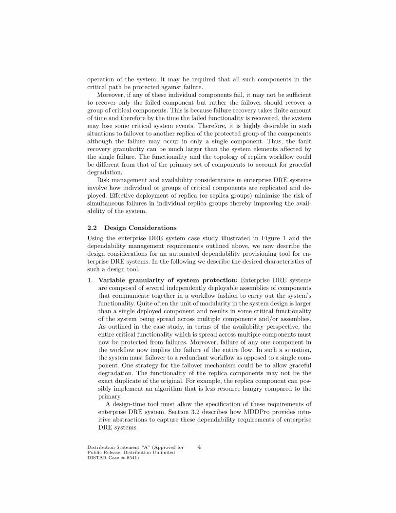
Figure 1 illustrates a sample enterprise DRE system drawn from representativedomains, such as avionics mission computing or shipboard computing, wherevariables of interest are sensed by the sensor equipment, which are softwarecontrolled and fed to a set of planners who determine the appropriate controlaction to be taken, and subsequently relay this information to the actuatorsoftware components.
Fig. 1: A Sample Enterprise DRE System
Enterprise DRE systems are often deployed over heterogeneous platforms,which consist of multiple different networks, hardware and several layers of soft-ware. We consider the fact that failures may occur in any of these entities. Forexample, node failures, operating system crashes, middleware broker process fail-ures, and even network link failures are common. In our current discussion wedo not consider multiple cascaded failures.
Quite often the critical functionality of enterprise DRE systems is spreadacross multiple components. For example, the planning activity in Figure 1 isspread across two planning components, which could be deployed in separateapplication servers on different hosts. Since these distributed set of componentsform a unit of critical functionality, for high availability and even for the correct
Distribution Statement “A” (Approved forPublic Release, Distribution UnlimitedDISTAR Case # 8541)
3
operation of the system, it may be required that all such components in thecritical path be protected against failure.
Moreover, if any of these individual components fail, it may not be sufficientto recover only the failed component but rather the failover should recover agroup of critical components. This is because failure recovery takes finite amountof time and therefore by the time the failed functionality is recovered, the systemmay lose some critical system events. Therefore, it is highly desirable in suchsituations to failover to another replica of the protected group of the componentsalthough the failure may occur in only a single component. Thus, the faultrecovery granularity can be much larger than the system elements affected bythe single failure. The functionality and the topology of replica workflow couldbe different from that of the primary set of components to account for gracefuldegradation.
Risk management and availability considerations in enterprise DRE systemsinvolve how individual or groups of critical components are replicated and de-ployed. Effective deployment of replica (or replica groups) minimize the risk ofsimultaneous failures in individual replica groups thereby improving the avail-ability of the system.
2.2 Design Considerations
Using the enterprise DRE system case study illustrated in Figure 1 and thedependability management requirements outlined above, we now describe thedesign considerations for an automated dependability provisioning tool for en-terprise DRE systems. In the following we describe the desired characteristics ofsuch a design tool.
1. Variable granularity of system protection: Enterprise DRE systemsare composed of several independently deployable assemblies of componentsthat communicate together in a workflow fashion to carry out the system’sfunctionality. Quite often the unit of modularity in the system design is largerthan a single deployed component and results in some critical functionalityof the system being spread across multiple components and/or assemblies.As outlined in the case study, in terms of the availability perspective, theentire critical functionality which is spread across multiple components mustnow be protected from failures. Moreover, failure of any one component inthe workflow now implies the failure of the entire flow. In such a situation,the system must failover to a redundant workflow as opposed to a single com-ponent. One strategy for the failover mechanism could be to allow gracefuldegradation. The functionality of the replica components may not be theexact duplicate of the original. For example, the replica component can pos-sibly implement an algorithm that is less resource hungry compared to theprimary.
A design-time tool must allow the specification of these requirements ofenterprise DRE system. Section 3.2 describes how MDDPro provides intu-itive abstractions to capture these dependability requirements of enterpriseDRE systems.
Distribution Statement “A” (Approved forPublic Release, Distribution UnlimitedDISTAR Case # 8541)
4

2. Mixed-mode dependability requirements: Enterprise DRE systems arelarge-scale and comprise several different components each of which ac-complishing specific tasks of the entire system functionality. Some parts ofthe system may require ultra high reliability mandating active replicationschemes. However, due to the overhead associated with active replicationand the non determinism issues [4, 5] involved in active replication, it maybe necessary to restrict the use of active replication to a small part of theenterprise DRE systems. Other parts of the system may then use other formsof replication, such as passive replication, or depend on simple restart mech-anisms depending on the criticality of the component and available resourcesin the system.
The design-time tool must enable enterprise DRE system developers tocapture these mixed-mode dependability semantics of the system. Whencombined with the granularity of protection units and other performancerequirements of the system, this provisioning task becomes complex to per-form manually using ad hoc and programmatic techniques. Section 3.2 de-scribes how MDDPro provides intuitive abstractions to capture mixed-modedependability requirements of enterprise DRE systems.
3. Effective replica deployment for maximizing availability: As alludedto above, enterprise DRE systems may have a number of different protectedunits of functionality that are assembled together to form the system. More-over, different parts of the system may use different replication schemes.Considering both these requirements, it is now necessary to introduce re-dundancy in the system that accounts for the units of protection used andthe replication styles used. Redundancy in the system improves system avail-ability, however, high levels of reliability are realized only when replicas areplaced in such a way that the risk of simultaneous failures of replicas is min-imized. Effective replica placement also impacts several other performancecharacteristics of the entire system. For example, effective replica placementmay be necessary to maintain a bounded and fast state synchronizationamong the replicas.
A design-time tool can be used to ensure that the system simultaneouslysatisfies multiple QoS requirements such as performance, predictability andavailability, by incorporating deployment state space search algorithms thatautomatically find effective deployments. This feature boils down to the gen-eral problem of constraint satisfaction. Optimality is a harder problem thanconstraint satisfaction, however, we do not consider it yet in our design. Sec-tion 3.3 describes how we have designed our MDDPro tool that can plugin different replica placement algorithms that find effective deployments forenterprise DRE systems.
4. Automated provisioning of dependability: Even though the modelingtechniques can help capture dependability requirements while replica place-ment algorithms can provide effective deployment decisions, these must ul-timately be realized in the context of the underlying hosting platforms, suchas the component middleware. Component middleware often use XML meta-
Distribution Statement “A” (Approved forPublic Release, Distribution UnlimitedDISTAR Case # 8541)
5

data that describes how components of an enterprise DRE system should behosted in the middleware and how they must be connected to each other.For large-scale systems, the amount of metadata becomes very large andad hoc techniques, such as handcrafting these descriptors becomes infeasibleand error prone.
Dependability provisioning makes this task harder since the metadatamust now account for the protection units and provisioning the multiplereplication schemes within the enterprise DRE system. This requires sub-stantial degree of middleware configuration by allocating different resourcesend-to-end. Replication adds to the number of connections that must beestablished between the different protection units and their replicas. Thereplication style makes this task even harder. For example, when active repli-cation is used, the middleware must be configured to use a group commu-nication substrate that is used by the communication between replicas. Onthe other hand, in passive replication, the secondary replicas must be provi-sioned on the middleware to accept periodic state updates from the primary.Section 3.4 describes how generative programming [6] techniques used withinour MDDPro tool automates the metadata generation to provision depend-ability for enterprise DRE systems within the middleware platforms.
Solution Approach. Model Driven Engineering (MDE) [3] is a promisingapproach to provision the dependability requirements for enterprise DRE sys-tems because it raises the level of the abstraction of system design to a levelhigher than third-generation programming languages by providing a scalableand intuitive abstractions that are closer to the domain. The model-per-concernparadigm within MDE alleviates system complexity because it abstracts awaythe irrelevant details from the developer’s current “view” of the system. Genera-tive tools provided by MDE approaches can seamlessly integrate multiple viewsof the system and produce a consistent set of metadata used by underlying hard-ware/software platforms for configuration. The MDDPro tool described in thispaper is therefore based on the MDE approach.
3 Dependability Provisioning using Model-drivenEngineering
In this section we describe the design and implementation of our MDDProdesign-time, automated dependability provisioning tool, which uses a model-driven engineering (MDE) approach in its design and satisfies the requirementsof such a tool outlined in Section 2.2.
3.1 Overview of Enabling Technologies
Before delving into the details of our design-time dependability provisioning tool,we first provide an overview of the enabling technologies we have leveraged todevelop MDDPro.
Distribution Statement “A” (Approved forPublic Release, Distribution UnlimitedDISTAR Case # 8541)
6

MDDPro has been developed in the context of the CoSMIC (Component Syn-thesis with Model Integrated Computing) [7] MDE toolsuite. CoSMIC is an opensource MDE tool suite used to simplify the development of component-basedDRE applications focusing particularly on the assembly, deployment, configu-ration, and validation of component-based enterprise DRE systems. CoSMICcomprises a collection of domain-specific modeling languages (DSMLs), whichdefine the concepts, relationships, and constraints used to express domain en-tities [8], and generative programming capabilities that automate the differentdevelopment concerns of DRE systems.
The different capabilities in CoSMIC including the MDDPro tool describedin this paper have been developed using the Generic Modeling Environment(GME) [9]. GME is a metaprogrammable modeling environment that enablesdomain experts to develop visual modeling languages and generative tools asso-ciated with those languages. The modeling languages in GME are representedas metamodels. A metamodel in GME depicts a class diagram using UML-likeconstructs showcasing the elements of the modeling language and how they areassociated with each other.
A key CoSMIC DSML developed in GME is the Platform Independent Com-ponent Modeling Language (PICML) [10], which enables graphical manipulationof modeling elements, such as component ports and attributes. PICML alsoperforms various types of generative actions, such as synthesizing XML-baseddeployment plan descriptors defined in the OMG Deployment and Configuration(D&C) specification [11]. CoSMIC provides the Component QoS Modeling Lan-guage (CQML), which is a mapping of the platform-independent PICML modelsto models that are specific to the lightweight CORBA Component Model. Fig-ure 2 illustrates the CQML model for the enterprise DRE system case studyfrom Figure 1. Our MDDPro tool is an enhancement to the CQML DSML andits generative capabilities.
3.2 Modeling Dependability Requirements in MDDPro
We now describe how the MDDPro tool addresses Requirements (1) and (2)described in Section 2.2. CQML allows modelers to annotate the system elementsmodeled with platform-specific details and different quality of service (QoS)requirements as shown in Figure 2. MDDPro is responsible for the dependabilityQoS attributes in CQML. The artifacts that can be annotated are componentinstances, component implementations, connections between component ports,component assemblies, among others.
MDDPro allows an enterprise DRE system deployer to model the dependabil-ity requirements in the QoS view of the DRE system as shown in Figure 3. TheQoS view leverages the basic structure of the DRE system in terms of the com-ponent instances in an assembly, component ports and their inter connections. Itallows FT elements to be modeled orthogonally to the system components andtherefore achieves separation of dependability concerns from the primary systemcomposition and functionality concerns.
The following modeling elements are supported within MDDPro:
Distribution Statement “A” (Approved forPublic Release, Distribution UnlimitedDISTAR Case # 8541)
7

Fig. 2: CQML Model of the Enterprise DRE System Case Study
• Failover units (FOUs), which enable control over the granularity of pro-tected system components, such as software components, component assem-blies, or entire component workflows. Failure of any one element belongingto a FOU is treated equivalent to the failure of all the elements in the FOUand the system effectively “fails over” to another replica of the FOU. Thismodeling abstraction not only captures the failover granularities of systementities, but also the degree of replication for each FOU and other systemicrequirements, such as the periodicity of liveness monitoring for FOUs. Thedegree of replication is represented as a pair of numbers representing mini-mum and maximum number of replicas. The programming language artifactsthat implement the replica components could be different from that of theprimary components allowing graceful degradation of the functionality if thedependability solution desires it.
Frequently, the liveness of distributed components is monitored using a“heart beat” protocol. The frequency of the heartbeat is one configurableparameter in the liveness monitoring, which can be configured in MDDPro.The heartbeat itself is configurable in two ways: push model or pull model.Thus, the directionality of the heartbeat can also be configured in MDDPro.In Section 3.4 we show how modeling of FOUs enable us to automaticallysynthesize and configure liveness monitoring components as well as heartbeatproducing components. Conceptually, a FOU is an abstraction to capture theavailability requirements at the control plane of the dependability solution.
• Replication groups (RGs), which allows capturing the replication re-quirements of software components within a FOU. These models specifyreplication strategies, such as active, passive or other variants, and the state
Distribution Statement “A” (Approved forPublic Release, Distribution UnlimitedDISTAR Case # 8541)
8

Fig. 3: Availability Requirements Modeling in CQML
synchronization policies for components. A replication group captures theconfiguration parameters related to the data plane of the deployment so-lution. Multiple replicas of the system components synchronize their statewith each other as per the configuration of the data plane. For example,data synchronization frequency of the replicas is configurable. Moreover, thetopology of state synchronization among replicas is also a data plane levelconfiguration issue handled in MDDPro.
• Shared Risk Groups (SRGs), which defines one way of grouping of theresources in the target network of the applications that share a risk of simul-taneous failure. Application components share a risk of simultaneous failureby virtue of the failure of the resources they share, such as processes, nodes,racks or even data centers on which they are hosted. Risk factors are deter-mined by assigning the metrics, such as co-failure probabilities to a hierarchyof the network resources in a risk group that affects the availability of thesystem. The computation of the co-failure probabilities themselves is beyondthe scope of this paper and is assumed to be done apriori using reliabilityengineering methodologies.
The primary purpose behind modeling the shared risk groups and theirrespective co-failure probabilities is to facilitate automated deployment deci-
Distribution Statement “A” (Approved forPublic Release, Distribution UnlimitedDISTAR Case # 8541)
9

sions of the components in the system such that the probability of failure ofentire system is minimized thereby increasing the availability. One way of re-ducing the co-failure probability is to increase the physical distance betweenthe nodes where the components are deployed. Here, the physical distancecan be thought of as the distance from a remote host or a remote blade or aremote data center and so on. An advantage of using distance metric is thatit is simpler and quite intuitive than co-failure probability. In Section 3.3 weshow how the shared risk group model is used by the MDDPro model in-terpreter to determine a suitable and effective deployment that satisfies theavailability requirements and minimizes risks of simultaneous failures. Inour prototype implementation of the algorithm we use the simpler distancemetric to guide the decision of the replica placement.
Fig. 4: Shared Risk Group Hierarchy Modeling in CQML
The Figure 4 shows a model of the Shared Risk Group hierarchy. Hosts 1 to5 are part of a domain and are contained under a common “RootRiskGroup”at the top. A RootRiskGroup represents comparatively larger structuressuch as a ship or an entire building. All the hosts in the domain share acommon risk of failure of the largest composing structure represented by aRootRiskGroup. We limit the scope of our dependability solution at thatlevel. The RootRiskGroup is further divided in to smaller units of SharedRisk Groups as shown in the figure. For example, Host1, Host4 and Host5
Distribution Statement “A” (Approved forPublic Release, Distribution UnlimitedDISTAR Case # 8541)
10

share a common risk of a failure of the NodeGroup1 but failure of Node-Group2 that consists of Host4 and Host 5 does not affect Host1.The distance between hosts is simply computed as the number of tree edgesbetween two hosts. For example, the distance between the Host2 and Host3is 2. Similarly the distance between the Host2 and the Host4 or Host5 is5. Based on such a Shared Risk Group hierarchy, deployment decisions aretaken to maximize the distance between the primary component and itsreplicas as shown in the Figure 4
3.3 Improving Availability via Effective Replica Placement
Requirement (3) in Section 2.2 states that the dependability solution for enter-prise DRE systems must minimize the risk of simultaneous failures of replicatedfunctionality. This requires effective replica placement algorithms, where replica-tion is provided for protection units that are modeled as failover units describedin Section 3.2.
MDDPro uses GME’s plugin capabilities to add model interpreters. One suchmodel interpreter addresses the replica placement problem. The placement modelinterpreter provides a strategizable framework that can use different constraint-based algorithms to determine an effective replica placement plan to minimizethe co-failure probability of the system as a whole.
Formulation of replica placement problem instance in MDDPro. Inone instantiation of the formulation of the replica placement problem within ourstrategizable model interpreter, we use mathematical vectors to represent thedistance of the replicas from the primary component. If the primary componenthas N replicas, then we form N orthogonal vectors, where each vector representsthe distance from the primary component node in terms of hops captured in theshared risk group hierarchy. The magnitude of the resultant vector of the Northogonal vectors is used to compare different deployment configurations andto find the one that satisfies the constraints.
In this formulation of the placement problem algorithm, we have taken careto avoid generation of some obviously undesirable deployment configurations ofthe system. For example, it does not allow deployment configuration where allthe replicas of a component are located in the same host. This is obviously unde-sirable in dependable enterprise DRE systems because placing multiple replicasin the same host increases the risk of simultaneous failure of replicas.
Prototype heuristic algorithm using the distance metric. The pro-totype placement algorithm that we have developed maximizes the distance ofthe replicas from the primary replica but the pair-wise distance between repli-cas themselves can be small. In other words, the replicas themselves can grouptogether in closely located hosts that are farthest from the primary host. Such adeployment configuration is skewed and undesirable. To alleviate the problem weapply a penalty function to the resultant magnitude of the vector. The penaltyfunction gives more precedence to uniform deployments than highly skewed de-ployments. The penalty function that we have used is a simple standard devia-tion of the distances of individual replicas from the primary component. We can
Distribution Statement “A” (Approved forPublic Release, Distribution UnlimitedDISTAR Case # 8541)
11

generate better configurations by penalizing highly skewed deployment configu-rations heavily compared to the more uniform deployment configurations.
For example, consider two resultant vectors v1{4, 4, 4} and v2{1, 1, 8} having3 dimensions. Although the magnitude of v2 is much greater than v1, the deploy-ment configuration captured in v1 is more desirable than v2 because the replicasare spread across more uniformly around the primary unlike v2. The heuris-tic algorithm for the prototype implementation of the deployment algorithm isillustrated in Listing 1.
1. Compute the distance from each of the replicas to the primary for a placement.
2. Record each distance as a vector, where all vectors are orthogonal.
3. Add the vectors to obtain a resultant.
4. Compute the magnitude of the resultant.
5. Use the resultant in all comparisons (either among placements or against a threshold)
6. Apply a penalty function to the composite distance (e.g. pairwise replica distance)
Listing 1: Replica Placement Heuristics
3.4 Automated Dependability Provisioning via GenerativeProgramming
The model interpreters and generative tools in MDDPro use the dependabilityrequirements captured in the models for synthesizing metadata used to provisiondependability for enterprise DRE systems. In order to realize such an automationin the provisioning process several artifacts of dependability must be addressed:(a) the designer of the dependable system has to annotate the desired degree ofreplication of the protected components in the model, (b) the generative toolshave to process the replication requirements and produce deployment metadatathat reflects the number of physical software components that will actually bedeployed but not necessarily be represented in the model, (c) derive the complexconnection topology interconnecting the generated components, which is dic-tated by the degree and style of replication of the primary component as well asreplication requirements of the components it interacts with, and (d) generatingthe fault-tolerance infrastructure components that produce a periodic heartbeatas well as monitor the liveness of the replicated components.
Deployment metadata generation framework As noted in Section 3.1,the real-time component middleware platforms used to host the enterprise DRE
Distribution Statement “A” (Approved forPublic Release, Distribution UnlimitedDISTAR Case # 8541)
12

systems use standardized XML-based metadata descriptors to describe the de-ployment plans of the entire system, which the runtime system uses to actuallydeploy the different components of the system. Our challenge involved enhanc-ing the metadata descriptors to include dependability provisioning decisions. Forthis goal to realize, MDDPro’s generative capabilities had to be integrated withthe existing generators available in CQML without obtrusive changes to exist-ing capabilities. This approach ensures that generators for QoS issues beyonddependability, such as security, can seamlessly be integrated with CQML.
To address these concerns, we have developed an extensible framework calledThe Deployment Plan Framework that allows augmentation of metadata gener-ation “on-the-fly” as it is being generated. The framework exposes a fixed setof hooks to be filled in by the developer of the existing and any new CQMLmodel interpreters including the MDDPro model interpreters. The main job ofthe deployment framework is to generate the standardized metadata describ-ing the components, their implementations, their inter-connections and so on.Additionally, it invokes predefined hook methods implemented by different QoSmodel interpreters of CQML. The MDDPro interpreter implements a subset ofa large set of different possible hook methods. The hook methods “inject” auto-generated standardized metadata in response to the availability requirementscaptured in the model. The metadata generated on-the-fly blends into the otherstandardized metadata.
This architecture allows large scale reuse of earlier code base that deals withthe basic structure and composition capabilities of PICML/CQML. The de-veloper producing QoS enhancements to the existing modeling capabilities ofCQML need not be concerned with the other complexity of the framework andthe format of the standardized descriptors, but simply add/modify the metadatafor the QoS dimension they are addressing. Our MDDPro model interpreter ex-ploits these capabilities of the Deployment Plan Framework to ”inject” threedifferent kinds of metadata.
1. Replica component instances of the primary protected component de-pending upon replication degree annotated in the model. For example, ifreplication degree of an FOU is 3, then two replicas of the primary FOU arecreated. Thus, two replicas of each component in the FOU are effectivelyadded by the interpreter.
2. Component connection metadata is injected based on the replicationstyle and degree of replication. The incoming connections to the protectedcomponents are marked with special annotations so that the run-time sys-tem can use suitable implementations to realize them. One such possibleannotation is IOGR, i.e. Interoperable Object Group Reference. IOGR is apart of the FT-CORBA [2] standard.
3. Deployment metadata is the assignment of components to computingresources available in the system. This metadata includes information forall the primary protected components, their replicas and the dependabilityinfrastructure components (e.g. Heartbeat components).
Distribution Statement “A” (Approved forPublic Release, Distribution UnlimitedDISTAR Case # 8541)
13

Handling complex connections As shown in Figure 5, shows the effect ofthe replication style and the degree of replication on the complexity of the con-nection establishment. In an unprotected system, the Processor component andthe Planner component have exactly one connection between them. The Fig-ure 5 captures the multiplicative increase in the number of connections whenboth, the Processor component and the Planner component, are protected usingactive replication. Each Processor component, primary as well as its replica hasto make three connections to each member of the Planner replica group becausethe degree of replication of the Planner fail over unit (FOU) is three. In general,if the source component of the connection is replicated M times and the desti-nation component is replicated N times then the number of connections grow bya factor of M x N.
Fig. 5: Complexity of connection generation
Note that the diagram only indicates the necessary number of connectionsthe middleware has to establish when components are deployed. These connec-tion may or may not actually be used to send requests across because it really
Distribution Statement “A” (Approved forPublic Release, Distribution UnlimitedDISTAR Case # 8541)
14

depends upon where request/reply suppression is in place. Nevertheless, the com-ponent container has to prepare for any unforeseen failures and has to establishconnections apriori in order to avoid the latency of connection establishmentlater when failures occur. The model interpreter that we have developed com-pletely hides away the complexity of modeling the component replica instancesand the connections between them.
Automatic generation of liveness monitoring infrastructure The modelinterpreter also generates the infrastructure components necessary for livenessmonitoring of the protected components. It uses the availability requirementsin the models to generate supporting run-time components to realize ready-to-deploy, robust, and fault-tolerant enterprise DRE systems. This includes gener-ating, configuring, and deploying the status monitoring and fault recovery com-ponents without the need for the application developer having to model/developthem explicitly.
Fig. 6: Generated Deployment of Dependability Infrastructure Elements
The generated architecture shown in Figure 6 has two important compo-nents: the heartbeat (HB) component and the Fault Protection Center compo-nent (FPC). The purpose of the HB components is to send a periodic heartbeatbeacon to the FPC or respond to the periodic liveness poll request received fromthe FPC. The FPC is the central controlling component that ensures the livenessof the protected components using either pull or push model of the heartbeatbeacon. The HB components are collocated with the protected components. The
Distribution Statement “A” (Approved forPublic Release, Distribution UnlimitedDISTAR Case # 8541)
15

underlying assumption is that the HB component and the protected componentwould fail simultaneously in the face of a failure. The central FPC component isalso replicated to avoid single point of failure. Multiple copies of the FPC compo-nents send heartbeat beacons among themselves to ensure that FPC themselvesare alive and are doing continuous liveness monitoring of the system.
As shown in Figure 6, every protected component has its own collocatedHB component and there is one FPC for every FOU. All the HB componentsbelonging to one FOU send heartbeat to its corresponding FPC. Multiple simul-taneously active FOUs have equal number of FPCs, which communicate withthemselves to prevent single point of failure.
The heartbeat frequency at which the liveness indications are sent betweenHBs and FPCs is configurable in the model. The advantage of this architecture isthat the infrastructure components for liveness monitoring can be auto-generatedusing generative technologies. The necessary deployment metadata required tocollocate the HB components with their respective protected components and toestablish the connections between HB components and the FPC components isauto-generated by the model interpreter from the requirements. Moreover, themetadata that captures the configuration of HB components such as push/pullmodel and heartbeat frequency is auto-generated for every HB component.
4 Related Work
Although there has been substantial research in dependability mechanisms andalgorithms over the past several decades, applying modeling and generative tech-niques to automate dependability provisioning has recently caught researchers’attention. In this section we compare our work on model-driven engineering ofdependability with related research.
The CORRECT project [12] describes a project that is looking at applyingstep-wise refinement and OMG’s Model Driven Architecture [13] to automati-cally generate Java code used in a fault tolerant distributed system. The projectuses UML to describe the software architecture in both a platform-independentand platform-specific form. Model-to-model transformations are used to incre-mentally enrich the models with platform-specific artifacts until the Java skele-ton code is generated. MDDPro, on the other hand, is designed to automaticallygenerate the complete source code (not just the skeletons) for the componentliveness monitoring infrastructure that detects exceptional conditions.
[14] focuses on a research that provides platform-independent means to sup-port reliability design following the principles of a model driven architecture andapproach. The research aims to systematically address dependability concernsfrom the early to the late stages of software development by expressing depend-ability architectures using profiles. Design profiles are mapped to deploymentdomains, where the reliability configurations of how the components communi-cate and are distributed is explained. Unlike [14], MDDPro uses an extensibleway to automatically generate platform specific metadata and programming lan-guage artifacts that realize parts of the dependability provisioning solution.
Distribution Statement “A” (Approved forPublic Release, Distribution UnlimitedDISTAR Case # 8541)
16

[15] focuses on a research that uses UML to model application architecturesfor composite web services. The UML representation is based on BPEL, and ex-tensions are added to characterize the fault behavior of the elements comprisingthe web services. Model transformations are used to map the UML models toBlock Diagrams, Fault Trees and Markov models to analyze the dependabilitycharacteristics of the composite web services. On the other hand, our approach inMDDPro enhances the productivity of the system developers rather than systemdependability analysts.
Although our research on MDDPro has similar goals, we use the concept ofdomain-specific modeling languages, which provides more richer and semanti-cally powerful modeling concepts than the general-purpose modeling elementsprovided by UML. Additionally our framework allows plugging in multiple dif-ferent model interpreters that can synthesize metadata for multiple differentmiddleware platforms provide deployment planning.
5 Conclusions
This paper describes how model driven engineering (MDE) can be used to sim-plify and automate dependability provisioning in enterprise distributed real-timeand embedded (DRE) systems. We describe the capabilities of the MDDPro(Model Driven Dependability Provisioning) MDE tool which we have built aspart of the CoSMIC tool suite. Our work is suitable for component-orientedsystems that have multiple different quality of service requirements and whichare deployed and configured via declarative mechanisms. Both these traits arecommon to systems that use the service oriented architecture. In the remainderof this section we describe the lessons we learned in this effort and our futurework in this realm.
Lessons Learned and Future Work
Capturing availability requirements in terms of degree of replication, replicationstyle at the modeling time and generating component infrastructure componentsincreases productivity to a great extent but many unresolved challenges stillremain.
• Availability model analysis is useful to determine the effect of the avail-ability requirements on other QoS aspects of the system. Our prototypeimplementation of MDDPro is simplistic because it neglects the effects onsystem resource consumption due to replication. Unconstrained increase inthe degree of replication of the protected components in the system may re-sult in excessive resource consumption and may adversely affect other QoSguarantees of the system such as timeliness and CPU load. An analysis tech-nique needs to be in place that would help the system designers take correctdecisions about the system availability without adversely affecting the re-source consumption and other QoS characteristics of the system.
Distribution Statement “A” (Approved forPublic Release, Distribution UnlimitedDISTAR Case # 8541)
17

• Run-time adaptation of the fault-tolerance infrastructure as well as thereplicated application components is highly desirable in enterprise DRE sys-tems because these systems usually exhibit modal behavior. System func-tionality as well QoS priorities may change as the mode of operation of thesystem changes. Our approach to the availability modeling is static in natureand depends on the availability of the target domain information and theirassociations with each other in terms of co-failure probability. Although theplacement model interpreter does take deployment decisions at design timeusing a strategizable constraint-solver framework, it does not make the sys-tem adaptive at run-time. Runtime monitoring subsystems such as RACEcan be used to implement a general purpose resource constraint-solver frame-work at runtime, not unlike the one we have in our design-time placementmodel interpreter. Such a framework would make intelligent (re)deploymentdecisions based on changing environment (failures, resource consumption)and modes of the eDRE systems.
• Ensuring state consistency across replicas of components or FOUs in ageneral is a challenge. Our availability model abstracts away the details ofthe fault monitoring part of the FT subsystem and generates componentbased infrastructure automatically for precisely doing that. However, statesynchronization and ensuring state consistency across replicated componentsof the system is a hard problem. The primary challenges in this space arecapturing and provisioning a variety of state synchronization mechanisms be-cause different component developers may implement different mechanismsas they see fit. Several different ways of ensuring state synchronization areused, for example, central repository/database-based approach, transmissionof periodic state updates using point-to-point communication or multicastcommunication. Modeling the topology transmission of state update mes-sages is also important in case of non repository-based techniques becausethe runtime failover critically depends on the order in which replica compo-nents receive state updates.
All artifacts described in this paper are available in open source from the CoS-MIC web site (www.dre.vanderbilt.edu/cosmic).
References
1. Object Management Group: Lightweight CCM FTF Convenience Document.ptc/04-06-10 edn. (June 2004)
2. Object Management Group: Fault Tolerant CORBA Specification. OMG Docu-ment orbos/99-12-08 edn. (December 1999)
3. Schmidt, D.C.: Model-Driven Engineering. IEEE Computer 39(2) (2006) 25–31
4. Pascal Felber and Priya Narasimhan: Experiences, Approaches and Challenges inbuilding Fault-tolerant CORBA Systems. Transactions of Computers 54(5) (May2004) 497–511
5. Priya Narasimhan and Tudor Dumitras and Aaron M. Paulos and Soila M. Pertetand Charlie F. Reverte and Joseph G. Slember and Deepti Srivastava: MEAD:
Distribution Statement “A” (Approved forPublic Release, Distribution UnlimitedDISTAR Case # 8541)
18

support for Real-Time Fault-Tolerant CORBA. Concurrency - Practice and Ex-perience 17(12) (2005) 1527–1545
6. Czarnecki, K., Eisenecker, U.W.: Generative Programming: Methods, Tools, andApplications. Addison-Wesley, Reading, Massachusetts (2000)
7. Gokhale, A., Schmidt, D.C., Natarajan, B., Gray, J., Wang, N.: Model DrivenMiddleware. In Mahmoud, Q., ed.: Middleware for Communications. Wiley andSons, New York (2004) 163–187
8. Karsai, G., Sztipanovits, J., Ledeczi, A., Bapty, T.: Model-Integrated Developmentof Embedded Software. Proceedings of the IEEE 91(1) (January 2003) 145–164
9. Ledeczi, A., Bakay, A., Maroti, M., Volgysei, P., Nordstrom, G., Sprinkle, J.,Karsai, G.: Composing Domain-Specific Design Environments. IEEE Computer(November 2001) 44–51
10. Balasubramanian, K., Balasubramanian, J., Parsons, J., Gokhale, A., Schmidt,D.C.: A Platform-Independent Component Modeling Language for DistributedReal-time and Embedded Systems. Elsevier Journal of Computer and SystemSciences (2006) 171–185
11. Object Management Group: Deployment and Configuration Adopted Submission.OMG Document mars/03-05-08 edn. (July 2003)
12. Capozucca, A., Gallina, B., Guelfi, N., Pelliccione, P., Romanovsky, A.: CORRECT- Developing Fault-Tolerant Distributed Systems. ERCIM News 64(1) (2006)
13. Object Management Group: Model Driven Architecture (MDA). OMG Documentormsc/2001-07-01 edn. (July 2001)
14. G.Rodrigues: A Model Driven Approach for Software Systems Reliability. In: Inthe proceedings of the 26th ICSE/Doctoral Symposium, May 2004 - Edinburgh,Scotland, ACM Press (May 2004)
15. Zarras, A., Vassiliadis, P., Issarny, V.: Model-Driven Dependability Analysis ofWeb Services. In: Proc. of the Intl. Symp. on Dist. Objects and Applications(DOA’04), Agia Napa, Cyprus (October 2004)
Distribution Statement “A” (Approved forPublic Release, Distribution UnlimitedDISTAR Case # 8541)
19