mdrive linear actuator - schneider electric
TRANSCRIPT

MDrive®
Linear Actuator Compact, integrated all-in-one linear motion systems

Medical Technology
Laboratory Automation
Electronics Manufacture, Material Handling
Packaging, Printing, Paper
Applications Reduce system cost, size, design and assembly time for a wide range of motion applications
© Schneider Electric Motion USA All Rights Reserved. REV080912 For the most recent product information, go to www.motion.schneider-electric.com

1 Microstepping drive
2 Stepper motor linear actuator:non-captive or external shaft
3 Integrated controller version4 Control options:
Plus or Hybrid 5 Encoder
6 Up to 8 I/O lines
Select the best control option for your linear application:
MDrive® Plus vs. MDrive® Hybrid
MDrive® Linear Actuator
Compact, integrated all-in-one linear motion systems
1
2
34
6
5
1
2
3
4
5
6
MDrive Plus • delivers simple point-to-point move profi les at the lowest cost
MDrive Hybrid Consider if your application demands more... • regulating and maintaining linear force at a set level • preventing unintentional stalling • overcoming transient system loading • minimizing motor heat • replacing servo and linear mechanics at a much lower cost
There is no change in the form factor between the two control options

2
Contents
MDrive®Plus Linear Actuator systems, sizes: 14, 17 and 23
MDrive® Linear Actuator
Product overview Presentation . . . . . . . . . . . . . . . . . . . . . . . . . . . . . . . . . . . . . . . . . . . . . . . . . . page 4 MDrive Plus . . . . . . . . . . . . . . . . . . . . . . . . . . . . . . . . . . . . . . . . . . . . . . . . page 4 MDrive Hybrid . . . . . . . . . . . . . . . . . . . . . . . . . . . . . . . . . . . . . . . . . . . . . . . page 5 Product groupings . . . . . . . . . . . . . . . . . . . . . . . . . . . . . . . . . . . . . . . . . . . page 6
MDrive Plus with step/direction input Description . . . . . . . . . . . . . . . . . . . . . . . . . . . . . . . . . . . . . . . . . . . . . . . . . . . page 8 Specifi cations . . . . . . . . . . . . . . . . . . . . . . . . . . . . . . . . . . . . . . . . . . . . . . . . . page 9 MDrive Plus with step / direction input Dimensions . . . . . . . . . . . . . . . . . . . . . . . . . . . . . . . . . . . . . . . . . . . . . . . page 10 Connectivity . . . . . . . . . . . . . . . . . . . . . . . . . . . . . . . . . . . . . . . . . . . . . . . page 13 Part numbers . . . . . . . . . . . . . . . . . . . . . . . . . . . . . . . . . . . . . . . . . . . . . . page 16
MDrive Plus Motion Control fully programmable Description . . . . . . . . . . . . . . . . . . . . . . . . . . . . . . . . . . . . . . . . . . . . . . . . . . page 20 Specifi cations . . . . . . . . . . . . . . . . . . . . . . . . . . . . . . . . . . . . . . . . . . . . . . . . page 21 MDrive Plus Motion Control, fully programmable Dimensions . . . . . . . . . . . . . . . . . . . . . . . . . . . . . . . . . . . . . . . . . . . . . . . page 22 Connectivity . . . . . . . . . . . . . . . . . . . . . . . . . . . . . . . . . . . . . . . . . . . . . . . page 25 Part numbers . . . . . . . . . . . . . . . . . . . . . . . . . . . . . . . . . . . . . . . . . . . . . . page 28
MDrive Plus Ethernet Description . . . . . . . . . . . . . . . . . . . . . . . . . . . . . . . . . . . . . . . . . . . . . . . . . . page 32 Specifi cations . . . . . . . . . . . . . . . . . . . . . . . . . . . . . . . . . . . . . . . . . . . . . . . . page 33 MDrive Plus EtherNet/IP Dimensions . . . . . . . . . . . . . . . . . . . . . . . . . . . . . . . . . . . . . . . . . . . . . . . page 34 Connectivity . . . . . . . . . . . . . . . . . . . . . . . . . . . . . . . . . . . . . . . . . . . . . . . page 35 Part numbers . . . . . . . . . . . . . . . . . . . . . . . . . . . . . . . . . . . . . . . . . . . . . . page 36
MDrive Plus CANopen Description . . . . . . . . . . . . . . . . . . . . . . . . . . . . . . . . . . . . . . . . . . . . . . . . . . page 38 Specifi cations . . . . . . . . . . . . . . . . . . . . . . . . . . . . . . . . . . . . . . . . . . . . . . . . page 39 MDrive Plus CANopen Dimensions . . . . . . . . . . . . . . . . . . . . . . . . . . . . . . . . . . . . . . . . . . . . . . . page 40 Connectivity . . . . . . . . . . . . . . . . . . . . . . . . . . . . . . . . . . . . . . . . . . . . . . . page 43 Part numbers . . . . . . . . . . . . . . . . . . . . . . . . . . . . . . . . . . . . . . . . . . . . . . page 46
System performance Motor specifi cations . . . . . . . . . . . . . . . . . . . . . . . . . . . . . . . . . . . . . . . . . . . page 76 Speed force characteristics . . . . . . . . . . . . . . . . . . . . . . . . . . . . . . . . . . . . . . page 77 Screw specifi cations . . . . . . . . . . . . . . . . . . . . . . . . . . . . . . . . . . . . . . . . . . . page 78 Nut specifi cations . . . . . . . . . . . . . . . . . . . . . . . . . . . . . . . . . . . . . . . . . . . . . page 79

3
Hybrid Motion Technology Overview . . . . . . . . . . . . . . . . . . . . . . . . . . . . . . . . . . . . . . . . . . . . . . . . . . . . page 50 Presentation . . . . . . . . . . . . . . . . . . . . . . . . . . . . . . . . . . . . . . . . . . . . . . . . . page 51
MDrive Hybrid Step • Torque • Speed Description . . . . . . . . . . . . . . . . . . . . . . . . . . . . . . . . . . . . . . . . . . . . . . . . . . page 52 Specifi cations . . . . . . . . . . . . . . . . . . . . . . . . . . . . . . . . . . . . . . . . . . . . . . . . page 53 MDrive Hybrid with step, torque, and speed input Dimensions . . . . . . . . . . . . . . . . . . . . . . . . . . . . . . . . . . . . . . . . . . . . . . . page 54 Connectivity . . . . . . . . . . . . . . . . . . . . . . . . . . . . . . . . . . . . . . . . . . . . . . . page 55 Part numbers . . . . . . . . . . . . . . . . . . . . . . . . . . . . . . . . . . . . . . . . . . . . . . page 56
MDrive Hybrid Motion Control fully programmable Description . . . . . . . . . . . . . . . . . . . . . . . . . . . . . . . . . . . . . . . . . . . . . . . . . . page 58 Specifi cations . . . . . . . . . . . . . . . . . . . . . . . . . . . . . . . . . . . . . . . . . . . . . . . . page 59 MDrive Hybrid Motion Control, fully programmable Dimensions . . . . . . . . . . . . . . . . . . . . . . . . . . . . . . . . . . . . . . . . . . . . . . . page 60 Connectivity . . . . . . . . . . . . . . . . . . . . . . . . . . . . . . . . . . . . . . . . . . . . . . . page 61 Part numbers . . . . . . . . . . . . . . . . . . . . . . . . . . . . . . . . . . . . . . . . . . . . . . page 62
MDrive Hybrid Ethernet Description . . . . . . . . . . . . . . . . . . . . . . . . . . . . . . . . . . . . . . . . . . . . . . . . . . page 64 Specifi cations . . . . . . . . . . . . . . . . . . . . . . . . . . . . . . . . . . . . . . . . . . . . . . . . page 65 MDrive Hybrid EtherNet/IP Dimensions . . . . . . . . . . . . . . . . . . . . . . . . . . . . . . . . . . . . . . . . . . . . . . . page 66 Connectivity . . . . . . . . . . . . . . . . . . . . . . . . . . . . . . . . . . . . . . . . . . . . . . . page 67 Part numbers . . . . . . . . . . . . . . . . . . . . . . . . . . . . . . . . . . . . . . . . . . . . . . page 68
MDrive Hybrid CANopen Description . . . . . . . . . . . . . . . . . . . . . . . . . . . . . . . . . . . . . . . . . . . . . . . . . . page 70 Specifi cations . . . . . . . . . . . . . . . . . . . . . . . . . . . . . . . . . . . . . . . . . . . . . . . . page 71 MDrive Hybrid CANopen Dimensions . . . . . . . . . . . . . . . . . . . . . . . . . . . . . . . . . . . . . . . . . . . . . . . page 72 Connectivity . . . . . . . . . . . . . . . . . . . . . . . . . . . . . . . . . . . . . . . . . . . . . . . page 73 Part numbers . . . . . . . . . . . . . . . . . . . . . . . . . . . . . . . . . . . . . . . . . . . . . . page 74
System performance Motor specifi cations . . . . . . . . . . . . . . . . . . . . . . . . . . . . . . . . . . . . . . . . . . . page 76 Speed force characteristics . . . . . . . . . . . . . . . . . . . . . . . . . . . . . . . . . . . . . . page 77 Screw specifi cations . . . . . . . . . . . . . . . . . . . . . . . . . . . . . . . . . . . . . . . . . . . page 78 Nut specifi cations . . . . . . . . . . . . . . . . . . . . . . . . . . . . . . . . . . . . . . . . . . . . . page 79
MDrive® Linear ActuatorContents
MDrive®Hybrid Linear Actuator systems, size 23

4
pictured: size 17 non-captive shaft style
Presentation MDrive® Plus Linear ActuatorProduct overview
Product offerMDrive® Plus Linear Actuator motion control products integrate a stepper motor linear actuator with mechanicals and electronics, ideal for machine builders who want an optimized motor with on-board electronics. The integrated electronics of MDrive Plus Linear Actuator products reduce the potential for problems due to electrical noise by eliminating the cable between motor and drive.
These MDrive Plus products feature 1.8° 2-phase stepper motor linear actuators integrated with microstepping drive, fully programmable controller and encoder, depending on the version. Products accept up to 20 resolution settings from full to 256 microsteps per full step, including: degrees, metric and arc minutes.
CompactnessMDrive Plus Linear Actuator products require very little space in a machine. The stepper motor linear actuator and electronics form a compact unit with small footprint. And signals are converted directly from rotary to linear motion, eliminating the need for belts and pulleys, rack and pinion, hydraulics, pneumatics or other mechanical system.
SimplicityIntegration of motor and electronics reduces installation costs and the potential for problems due to electrical noise by eliminating the cable between motor and drive. User-friendly PC commissioning software allows for rapid setup and confi guration.
All-inclusive QuickStart Kits are available to simplify initial functional setup and system testing of MDrive Plus Linear Actuators.
Ease of integrationMDrive Plus Linear Actuator products are available in four versions:
■ Step / direction input: stepper motor linear actuator and drive with optically isolated step and direction input via SPI communication
■ Motion Control: stepper motor linear actuator, drive and fully programmable controller with up to 8 I/O lines, configurable 10-bit analog input, and RS-422/485 communication
■ Ethernet: stepper motor linear actuator, drive and fully programmable controller with 4 I/O lines and ODVA-compliant EtherNet/IP protocol, also ModbusTCP
■ CANopen: stepper motor linear actuator, drive and controller with CANopen interface support CiA DS301 and DSP402 Device Profile for Drives and Motion Control
This open communication concept allows for integration into existing system environments.
FlexibilityMDrive Plus Linear Actuator products are available with 1.8° 2-phase stepper motor linear actuators in three sizes: NEMA 14 (36mm), NEMA 17 (42mm) and NEMA 23 (57mm). Each motor size offers specific advantages so these products can be used in a wide range of linear motion applications.
MDrive Plus Linear Actuator products are available with a power range from +12 VDC up to +75 VDC.
1 stepper motor linear actuator with non-captive or external shaft style
2 microstepping drive
3 integrated controller version
4 NEMA motor sizes 14, 17 and 23
5 up to 8 I/O lines
6 encoder option
7 screw options include length, pitch/lead, end fi nish, coating
8 communication protocols: SPI, RS-422/485, Ethernet, CANopen
2
4
1
7
3
8
6
5

5
Presentation
1 stepper motor linear actuator with non-captive or external shaft style
2 Hybrid Motion Technology™
3 microstepping drive
4 integrated controller version
5 up to 8 I/O lines
6 internal encoder
7 screw options include length, pitch/lead, end fi nish, coating
8 communication protocols: RS-422/485, Ethernet, CANopen
Product offerMDrive® Hybrid Linear Actuator motion control systems integrate a stepper motor linear actuator and electronics with Hybrid Motion Technology™ (HMT). HMT combines the best of servo and stepper motor technologies, while delivering unique capabilities and enhancements over both.
MDrive® Hybrid integrated motion control systems are changing the rules of motor control. These advanced, low cost motion systems are ideal for machine builders who want an optimized motor with on-board electronics. In addition to HMT’s numerous benefits, the integrated electronics of MDrive Hybrid systems reduce the potential for problems due to electrical noise by eliminating the cable between motor and drive.
These MDrive Hybrid systems feature 1.8° 2-phase stepper motor linear actuators integrated with microstepping drive and internal encoder integral to system operation. Products accept up to 20 resolution settings from full to 256 microsteps per full step, including: degrees, metric and arc minutes.
CompactnessMDrive Hybrid Linear Actuator products require very little space in a machine. The stepper motor linear actuator and electronics form a compact unit with small footprint. And signals are converted directly from rotary to linear motion, eliminating the need for belts and pulleys, rack and pinion, hydraulics, pneumatics or other mechanical system.
SimplicityIntegration of motor and electronics reduces installation costs and the potential for problems due to electrical noise by eliminating the cable between motor and drive. User-friendly PC commissioning software allows for rapid setup and confi guration.
All-inclusive QuickStart Kits are available to simplify initial functional setup and system testing of MDrive Hybrid Linear Actuators.
Ease of integrationMDrive Hybrid Linear Actuator systems are available in four versions:
■ Step • Torque • Speed: stepper motor linear actuator and integrated drive system with three operating modes including optically isolated step and direction, torque/force, and velocity/speed inputs, all with RS-422/485 communication
■ Motion Control: stepper motor linear actuator, drive and fully programmable controller with up to 8 I/O lines, configurable 10-bit analog input, and RS-422/485 communication
■ Ethernet: stepper motor linear actuator, drive and fully programmable controller with 4 I/O lines and ODVA-compliant EtherNet/IP protocol, also ModbusTCP
■ CANopen: stepper motor linear actuator, drive and controller with CANopen interface support CiA DS301 and DSP402 Device Profile for Drives and Motion Control
This open communication concept allows for integration into existing system environments.
FlexibilityMDrive Hybrid Linear Actuator systems are available with 1.8° 2-phase stepper motor linear actuator in a NEMA 23 (57mm).
MDrive Hybrid Linear Actuator systems have a power range of +12 to +60 VDC.
pictured: size 23 external shaft style
3
7
2
5
8
4
6
1
MDrive® Hybrid Linear ActuatorProduct overview
6
Presentation MDrive® Linear ActuatorProduct overview
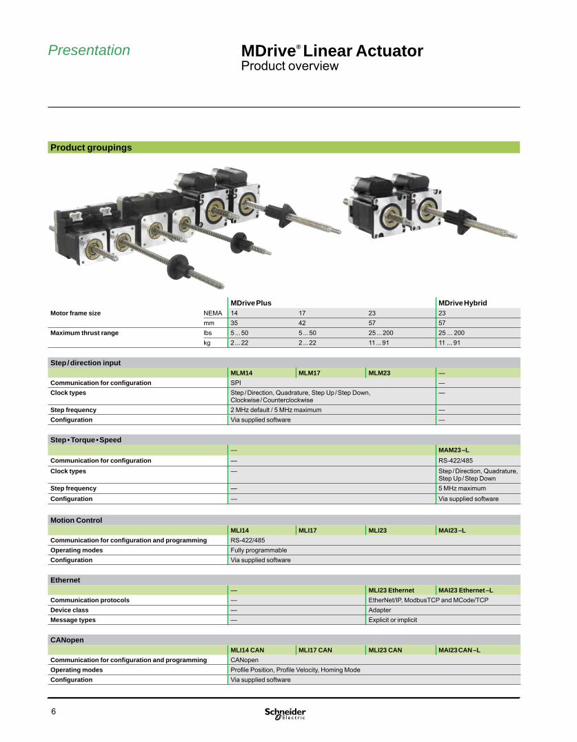
Product groupings
MDrive Plus MDrive HybridMotor frame size NEMA 14 17 23 23
mm 35 42 57 57Maximum thrust range lbs 5 ... 50 5 ... 50 25 ... 200 25 ... 200
kg 2 ... 22 2 ... 22 11 ... 91 11 ... 91
Step / direction inputMLM14 MLM17 MLM23 —
Communication for confi guration SPI —Clock types Step / Direction, Quadrature, Step Up / Step Down,
Clockwise / Counterclockwise—
Step frequency 2 MHz default / 5 MHz maximum —Confi guration Via supplied software —
Step • Torque • Speed— MAM23 –L
Communication for confi guration — RS-422/485Clock types — Step / Direction, Quadrature,
Step Up / Step DownStep frequency — 5 MHz maximumConfi guration — Via supplied software
Motion ControlMLI14 MLI17 MLI23 MAI23 –L
Communication for confi guration and programming RS-422/485Operating modes Fully programmableConfi guration Via supplied software
Ethernet— MLI23 Ethernet MAI23 Ethernet –L
Communication protocols — EtherNet/IP, ModbusTCP and MCode/TCPDevice class — AdapterMessage types — Explicit or implicit
CANopenMLI14 CAN MLI17 CAN MLI23 CAN MAI23 CAN –L
Communication for confi guration and programming CANopenOperating modes Profi le Position, Profi le Velocity, Homing ModeConfi guration Via supplied software

MDrive® Plus Linear ActuatorStep / direction input

8
MDrive® Plus Linear ActuatorStep / direction input
PresentationThe MDrive® Plus Linear Actuator with step /direction input is an integrated product that combines a stepper motor linear actuator with mechanicals and electronics to form a single, compact system. It features a 1.8° 2-phase stepper motor linear actuator with on-board control electronics. Step/direction signals of a master controller, e.g. a motion controller, or A/B signals of an encoder, are converted directly into rotary-to-linear motion. This eliminates the need for belts and pulleys, rack and pinion, hydraulics, pneumatics or other mechanical system.
Settings for MDrive Plus Linear Actuators with step / direction input may be changed on-the-fly or downloaded and stored in nonvolatile memory using the SPI Motor Interface software provided. This eliminates the need for external switches or resistors. Parameters are changed via an SPI port.
Application areasThe MDrive Plus Linear Actuator with step /direction input is ideal for machine builders who want an optimized stepper motor linear actuator with on-board electronics. The integrated electronics of the MDrive product reduces the potential for problems due to electrical noise by eliminating the cable between motor and drive.
These compact, powerful and cost effective linear motion control solutions deliver exceptional smoothness and performance, and may reduce system cost, design and assembly time for a large range of applications.
Features
■ Highly integrated microstepping drive and high torque 1.8° 2-phase stepper motor linear actuator Non-captive or external shaft style Load limit up to 200 lbs Precision rolled lead screws■ Advanced current control for exceptional performance and smoothness■ Single supply: from +12 up to +75 VDC■ Cost effective■ Extremely compact■ 20 microstep resolutions up to 51,200 steps per rev including: Degrees, Metric, Arc Minutes■ Optically isolated input options: Universal +5 to +24 VDC signals, sourcing or sinking Differential +5 VDC signals■ Automatic current reduction■ Configurable: Motor run / hold current Motor direction via direction input Microstep resolution Clock type: step and direction, quadrature, step up and step down, clockwise and counterclockwise Programmable digital filtering for clock and direction inputs■ Setup parameters may be switched on-the-fly■ Numerous connector interface choices■ Available options: Externally-mounted encoder (1) Drive Protection Module■ Graphical user interface (GUI) provided for quick and easy parameter setup (1) Only available for External shaft linear actuators.
Description
MDrive®Plus Linear Actuator with step / direction input,non-captive and external shaft styles

9
General specifi cationsMDrive 14 MDrive 17 MDrive 23
Input power Voltage VDC 12 to 48 12 to 48 12 to 75Current maximum (1) amp 1 2 2
Maximum thrust (2) Non-captive shaft lbs 50 50 200kg 22 22 91
External shaft with general purpose nut
lbs 25 25 60kg 11 11 27
External shaft with anti-backlash nut
lbs 5 5 25kg 2 2 11
Maximum repeatability General purpose inch 0.005mm 0.127
Anti-backlash (3) inch 0.0005mm 0.0127
Thermal Operating temp non-condensing
Heat sink – 40° to +85°CMotor – 40° to +100°C
Isolated input Universal Voltage range: +5 to +24 VDC sourcing or sinking step clock, direction and enableDifferential Voltage range: +5 VDC clockwise and counterclockwise
Motion Digital fi lter range 50 nS to 12.9 μS (10 MHz to 38.8 kHz)Clock types Step / direction, quadrature, step up / step down, clockwise / counterclockwiseStep frequency 2 MHz default / 5 MHz maximumMicrostep resolution Number of
settings20
Steps per revolution
200, 400, 800, 1000, 1600, 2000, 3200, 5000, 6400, 10000, 12800, 20000, 25000, 25600, 40000, 50000, 51200, 36000 (0.01 deg/μstep), 21600 (1 arc minute/μstep), 25400 (0.001 mm/μstep)
Setup parameters (4)SPI communication Function Range Units Default
MHC Motor hold current 0 to 100 percent 5MRC Motor run current 1 to 100 percent 25MSEL Microstep resolution 1, 2, 4, 5, 8, 10, 16, 25, 32, 50, 64, 100,
108, 125, 127, 128, 180, 200, 250, 256μsteps per full step
256
DIR Motor direction override 0 / 1 — CWHCDT Hold current delay time 0 or 2 – 65535 mSec 500CLK TYPE Clock type Step / Dir, Quadrature, Up / Down,
CW / CCW— Step / Dir
CLK IOF Clock and direction fi lter 50 nS to 12.9 μS (10 MHz to 38.8 kHz)
nS ( MHz)
200 nS (2 MHz)
USER ID User ID Customizable 1–3characters
IMS
EN ACT Enable active High / Low — High(1) Actual power supply current will depend on voltage and load.(2) Performance data for maximum force / load is based on a static load and will vary with a dynamic load.(3) Only applicable for External shaft linear actuator with anti-backlash nut.(4) All parameters are set using the supplied SPI Motor Interface GUI and may be changed on-the-fl y. An optional Communication Converter is recommended with fi rst orders.
MDrive® Plus Linear ActuatorStep / direction input
Specifi cations
See User Manual for complete details: www.motion.schneider-electric.com/manuals.html
10
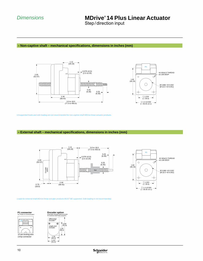
MDrive® 14 Plus Linear ActuatorStep / direction input
Dimensions
– External shaft – mechanical specifi cations, dimensions in inches (mm)
– Non-captive shaft – mechanical specifi cations, dimensions in inches (mm)
Ø 0.866 +0/-0.002(Ø 22.0 +0/-0.051)
1.4 ±0.004( 35.55 ±0.1)
4X M3x0.5 THREADx0.138 DEEP
1.82(46.19)
1.024( 26.0)
P1
2.05(52.07)
1.11(28.19)
0.079 ±0.01(2.0 ±0.25)
2.30(58.42)
0.25(6.35) 0.25
(6.35)
3.0 to 18.0(77.5 to 455.0)
Ø 0.866 +0/-0.002(Ø 22.0 +0/-0.051)
1.4 ±0.004( 35.55 ±0.1)
4X M3x0.5 THREADx0.138 DEEP
1.82(46.19)
1.024( 26.0)
P1
2.05(52.07)
1.11(28.19)
0.079 ±0.01(2.0 ±0.25)
2.30(58.42)
0.25(6.35)
0.25(6.35)
Nut
3.0 to 18.0(77.5 to 455.0)
0.70(18.0)
Enc
oder
op
tion
P1
12-pin locking wire crimp connector
I/O, Power & CommunicationP1 connector
Unsupported loads and side loading are not recommended for non-captive shaft MDrive linear actuator products.
Loads for external shaft MDrive linear actuator products MUST BE supported. Side loading is not recommended.
Encoder option
1.42(36.1)
2.04*(51.8)
differentialencoder*
.
1.22*(31.0)
.
single-endencoder
1.20(30.4)
Externally-mounted optical encoder, for External shaft linear actuators

11
MDrive® 17 Plus Linear ActuatorStep / direction input
Dimensions
– External shaft – mechanical specifi cations, dimensions in inches (mm)
– Non-captive shaft – mechanical specifi cations, dimensions in inches (mm)
0.25(6.35)
P1
2.30(58.3)
1.19(30.2)
0.08(2.0)
P2
0.25(6.35)
2.20(55.9)
1.59(40.5)
3.0 to 18.0(77.5 to 455.0)
Ø 0.866 +0/-0.002(Ø 22.0 +0/-0.051)
1.68( 42.7)
4X M3x0.5 THREADx0.15 MIN DEEP
1.220 ±0.004( 31.0 ±0.1)
P1
2.30(58.3)
1.19(30.2)
0.08(2.0)
P2
2.20(55.9)
1.59(40.5)
0.25(6.35)
0.25(6.35)
Nut
3.0 to 18.0(77.5 to 455.0)
0.70(18.0)
Enc
oder
op
tion
0.44(11.2)
P1
12.00 +1.0/-0.0 (304.8 +25.4/-0.0)
P1
P1 connector options
7-pin non-locking spring clamp terminal strip
12.0" (305mm) fl ying leads
12-pin locking wire crimp connector (1)
I/O & Power I/O & Power I/O, Power & Communication
P2
P2 connector options
10-pin non-locking IDC connector
no connector (1)
Communication Communication
P1
0.36(9.1)
P2
(1) 12-pin locking wire crimp connector at P1 eliminates the P2 connector.
Unsupported loads and side loading are not recommended for non-captive shaft MDrive linear actuator products.
Loads for external shaft MDrive linear actuator products MUST BE supported. Side loading is not recommended.
1.42(36.1)
2.04*(51.8)
differentialencoder*
.
1.22*(31.0)
.
single-endencoder
1.20(30.4)
Encoder optionExternally-mounted optical encoder, for External shaft linear actuators
Ø 0.866 +0/-0.002(Ø 22.0 +0/-0.051)
1.68( 42.7)
4X M3x0.5 THREADx0.15 MIN DEEP
1.220 ±0.004( 31.0 ±0.1)

12
P1
0.36(9.1)
P2I/O & Power I/O & Power I/O, Power & Communication
no connector (1)
MDrive® 23 Plus Linear ActuatorStep / direction input
Dimensions
P2
P1
0.44(11.2)
P1
12.00+1.0/-0.0
(304.8)(+25.4/-0.0)
P1 connector options
7-pin non-locking spring clamp terminal strip
12.0" (305mm) fl ying leads
12-pin locking wire crimp connector (1)
P2 connector options
10-pin non-locking IDC connector
Communication None
(1) 12-pin locking wire crimp connector at P1 eliminates the P2 connector.
– External shaft – mechanical specifi cations, dimensions in inches (mm)
– Non-captive shaft – mechanical specifi cations, dimensions in inches (mm)
1.90(48.3)
2.96(75.2)
0.06 ±0.00(1.5 ±0.1)
0.189 ±0.012(4.8 ±0.3)
1.34(34.0)
P2
P1
2.65(67.31)
0.375(9.525)
3.0 to 24.0(77.5 to 610.0)
0.50(12.7)
2.02(51.2)
Ø 1.500 ±0.002(Ø 38.1 ±0.1)
2.22( 56.4)
Ø 0.197 +0.012/-0(Ø 5.0 +0.3/-0)
1.63(41.4)
1.856 ±0.008 ( 47.1 ±0.2)
1.90(48.3)
2.96(75.2)
0.06 ±0.00(1.5 ±0.1)
1.34(34.0)
P2
P1
2.65(67.31)
0.19(4.9)
0.375(9.525)
0.50(12.7)
Nut
3.0 to 24.0(77.5 to 610.0)
Enc
oder
op
tion
0.70(18.0)
2.02(51.2)
Ø 1.500 ±0.002(Ø 38.1 ±0.1)
2.22( 56.4)
Ø 0.197 +0.012/-0(Ø 5.0 +0.3/-0)
1.63(41.4)
1.856 ±0.008 ( 47.1 ±0.2)
Unsupported loads and side loading are not recommended for non-captive shaft MDrive linear actuator products.
Loads for external shaft MDrive linear actuator products MUST BE supported. Side loading is not recommended.
1.42(36.1)
2.04*(51.8)
differentialencoder*
.
1.22*(31.0)
.
single-endencoder
1.20(30.4)
Encoder optionExternally-mounted optical encoder, for External shaft linear actuators

13
locking mating connector
PD12B-1434-FL3
MDrive® 14 Plus Linear ActuatorStep / direction input
Installation accessoriesDescription Length
feet (m)Part number
QuickStart KitFor rapid design verifi cation, all-inclusive QuickStart Kits include connectivity, instructions and CD for MDrive Plus Linear Actuator initial functional setup and system testing.■ For MDrive 14 Plus step / direction input products
— add "K" to part number (1)
Communication converterElectrically isolated, in-line con vert er pre-wired with mating connector to conveniently set/program communication parameters for a single MDrive Plus Linear Actuator via a PC's USB port.■ Mates to 12-pin locking wire crimp connector 12.0 (3.6) MD-CC305-001
Prototype development cableSpeed test/development with pre-wired mating connector with other cable end open.■ Mates to 12-pin locking wire crimp connector for I/O, communication and power
10.0 (3.0) PD12B-1434-FL3
Encoder cablesPre-wired mating connector with other cable end open.■ For external single-end optical encoder 1.0 (0.3) ES-CABLE-2
■ For external differential optical encoder with locking connector
6.0 (1.8) ED-CABLE-6
Mating connector kitConnectors for assembly of cables, cable material not supplied. Sold in lots of 5. Manufacturer's crimp tool recommended for crimp connectors.■ 12-pin locking wire crimp connector for I/O, communication and power
— CK-08
Drive protection moduleLimits surge current and voltage to a safe level when DC input power is switched on-and-off to an MDrive product.■ For all MDrive Linear Actuator products — DPM75
(1) See page 16.
Connectivity
USB connector
in-line converter
MDrive® Plus 12-pin wire crimpmating connector
to power & I/O
MD-CC305-001
Connectivity details: www.motion.schneider-electric.com/connect.html

14
MDrive® 17 Plus Linear ActuatorStep / direction input
Connectivity
Installation accessoriesDescription Length
feet (m)Part number
QuickStart KitFor rapid design verifi cation, all-inclusive QuickStart Kits include connectivity, instructions and CD for MDrive Plus Linear Actuator initial functional setup and system testing.■ For MDrive 17 Plus step / direction input products
— add "K" to part number (1)
Communication converterElectrically isolated, in-line con vert er pre-wired with mating connector to conveniently set/program communication parameters for a single MDrive Plus Linear Actuator via a PC's USB port.■ Mates to 10-pin non-locking IDC connector 12.0 (3.6) MD-CC300-001
■ Mates to 12-pin locking wire crimp connector 12.0 (3.6) MD-CC303-001
Prototype development cableSpeed test/development with pre-wired mating connector with other cable end open.■ Mates to 12-pin locking wire crimp connector for I/O, communication and power
10.0 (3.0) PD12-1434-FL3
Encoder cablesPre-wired mating connector with other cable end open.■ For external single-end optical encoder 1.0 (0.3) ES-CABLE-2
■ For external differential optical encoder with locking connector
6.0 (1.8) ED-CABLE-6
Mating connector kitConnectors for assembly of cables, cable material not supplied. Sold in lots of 5. Manufacturer's crimp tool recommended for crimp connectors.■ 10-pin non-locking IDC connector for communication
— CK-01
■ 12-pin locking wire crimp connector for I/O, communication and power
— CK-03
Drive protection moduleLimits surge current and voltage to a safe level when DC input power is switched on-and-off to an MDrive product.■ For all MDrive Linear Actuator products — DPM75
(1) See page 17.
MD-CC300-001
USB connector
in-line converter
MDrive® Plus 12-pin wire crimpmating connector
to power & I/O
MD-CC303-001
locking mating connector
PD12-1434-FL3
MDrive® Plus non-locking IDCmating connector
USB connector
in-line converter
Connectivity details: www.motion.schneider-electric.com/connect.html

15
MDrive® 23 Plus Linear ActuatorStep / direction input
Connectivity
Installation accessoriesDescription Length
feet (m)Part number
QuickStart KitFor rapid design verifi cation, all-inclusive QuickStart Kits include connectivity, instructions and CD for MDrive Plus Linear Actuator initial functional setup and system testing.■ For MDrive 23 Plus step / direction input products
— add "K" to part number (1)
Communication converterElectrically isolated, in-line con vert er pre-wired with mating connector to conveniently set/program communication parameters for a single MDrive Plus Linear Actuator via a PC's USB port.■ Mates to 10-pin non-locking IDC connector 12.0 (3.6) MD-CC300-001
■ Mates to 12-pin locking wire crimp connector 12.0 (3.6) MD-CC303-001
Prototype development cableSpeed test/development with pre-wired mating connector with other cable end open.■ Mates to 12-pin locking wire crimp connector for I/O, communication and power
10.0 (3.0) PD12-1434-FL3
Encoder cablesPre-wired mating connector with other cable end open.■ For external single-end optical encoder 1.0 (0.3) ES-CABLE-2
■ For external differential optical encoder with locking connector
6.0 (1.8) ED-CABLE-6
Mating connector kitConnectors for assembly of cables, cable material not supplied. Sold in lots of 5. Manufacturer's crimp tool recommended for crimp connectors.■ 10-pin non-locking IDC connector for communication
— CK-01
■ 12-pin locking wire crimp connector for I/O, communication and power
— CK-03
Drive protection moduleLimits surge current and voltage to a safe level when DC input power is switched on-and-off to an MDrive product.■ For all MDrive Linear Actuator products — DPM75
(1) See page 18.
MD-CC300-001
USB connector
in-line converter
MDrive® Plus 12-pin wire crimpmating connector
to power & I/O
MD-CC303-001
locking mating connector
PD12-1434-FL3
MDrive® Plus non-locking IDCmating connector
USB connector
in-line converter
Connectivity details: www.motion.schneider-electric.com/connect.html

16
MDrive® 14 Plus Linear ActuatorStep / direction input
Part numbers
MDrive® 14 Plus
P1: I/O, Power & CommunicationC = 12-pin locking wire crimp connector
Continued – Part numbersExample - linear actuator specifi cations: – L A 1 M 0 6 0 Z T
Linear actuator– L
– L A 1 M 0 6 0 Z T
Screw lead / pitchA = 0.250" / 6.35 mm travel per revB = 0.125" / 3.175 mm travel per revC = 0.063" / 1.588 mm travel per rev
– L A 1 M 0 6 0 Z T
Shaft style1 = Non-captive3 = External
– L A 1 M 0 6 0 Z T
Screw end fi nishM = metric threadedU = UNC threadedS = smoothZ = none
– L A 1 M 0 6 0 Z T
Screw length030 = 3.0" (77.5 mm) minimum up to180 = 18.0" (455.0 mm) maximum, in 0.1" (2.5 mm) increments
– L A 1 M 0 6 0 Z T
Nut Z = none, only with Non-captive shaft productsG = general purpose, only with External shaft products (2)A = anti-backlash, only with External shaft products (3)
– L A 1 M 0 6 0 Z T
CoatingT = Tefl onZ = None
– L A 1 M 0 6 0 Z T
(1) Only available with External shaft linear actuators.(2) Dynamic load limit to 25 lbs / 11 kg.(3) Dynamic load limit to 5 lbs / 2 kg.
Part numbersExample: K M L M 1 C S Z 1 4 A 4 – E1 –
QuickStart KitK = kit option, or leave blank if not wanted
K M L M 1 C S Z 1 4 A 4 – E1 –
MDrive Plus Linear Actuator versionMLM = Step / direction input
K M L M 1 C S Z 1 4 A 4 – E1 –
Input type1 = Universal input5 = Differential CW/CCW input
K M L M 1 C S Z 1 4 A 4 – E1 –
P1 connectorC = wire crimp
K M L M 1 C S Z 1 4 A 4 – E1 –
CommunicationS = SPI
K M L M 1 C S Z 1 4 A 4 – E1 –
P2 connector Z = none
K M L M 1 C S Z 1 4 A 4 – E1 –
Motor size14 = NEMA 14 (1.4" / 36 mm)
K M L M 1 C S Z 1 4 A 4 – E1 –
Motor lengthA = single stack
K M L M 1 C S Z 1 4 A 4 – E1 –
Drive voltage4 = +12 to +48 VDC
K M L M 1 C S Z 1 4 A 4 – E1 –
Optional encoder (1)Leave blank if not wanted– E___ = externally-mounted optical encoder with index mark
– E1 –
Linear actuator specifi cationsComplete the part number from the table below
–
Non-captive shaft style External shaft style
line count 100 200 250 256 400 500 512 1000 1024single-end part # E1 E2 E3 EP E4 E5 EQ E6 ERdifferential part # EAL EBL ECL EWL EDL EHL EXL EJL EYL
Easy MDrive part numbers via an interactive tool at: www.motion.schneider-electric.com/MDriveLinear.html

17
Part numbersExample: K M L M 1 F S D 1 7 A 4 – E1 –
QuickStart KitK = kit option, or leave blank if not wanted
K M L M 1 F S D 1 7 A 4 – E1 –
MDrive Plus Linear Actuator versionMLM = Step / direction input
K M L M 1 F S D 1 7 A 4 – E1 –
Input type1 = Universal input5 = Differential CW/CCW input
K M L M 1 F S D 1 7 A 4 – E1 –
P1 connectorF = fl ying leadsP = pluggableC = wire crimp (1)
K M L M 1 F S D 1 7 A 4 – E1 –
CommunicationS = SPI
K M L M 1 F S D 1 7 A 4 – E1 –
P2 connector D = IDCZ = none (1)
K M L M 1 F S D 1 7 A 4 – E1 –
Motor size17 = NEMA 17 (1.7" / 42 mm)
K M L M 1 F S D 1 7 A 4 – E1 –
Motor lengthA = single stack
K M L M 1 F S D 1 7 A 4 – E1 –
Drive voltage4 = +12 to +48 VDC
K M L M 1 F S D 1 7 A 4 – E1 –
Optional encoder (2)Leave blank if not wanted– E___ = externally-mounted optical encoder with index mark
– E1 –
Linear actuator specifi cationsComplete the part number from the table below
–
line count 100 200 250 256 400 500 512 1000 1024single-end part # E1 E2 E3 EP E4 E5 EQ E6 ERdifferential part # EAL EBL ECL EWL EDL EHL EXL EJL EYL
MDrive® 17 Plus Linear ActuatorStep / direction input
Part numbers
P2: CommunicationD = SPI with 10-pin IDC non-locking connectorZ = None. Used with 12-pin locking wire crimp in position P1, which includes communication.
P1: I/O & PowerF = 12" flying leadsP = non-locking spring clamp terminal stripC = 12-pin locking wire crimp (includes I/O, Power & Comm)
MDrive® 17 Plus
Continued – Part numbersExample - linear actuator specifi cations: – L A 1 M 0 6 0 Z T
Linear actuator– L
– L A 1 M 0 6 0 Z T
Screw lead / pitchA = 0.250" / 6.35 mm travel per revB = 0.125" / 3.175 mm travel per revC = 0.063" / 1.588 mm travel per rev
– L A 1 M 0 6 0 Z T
Shaft style1 = Non-captive3 = External
– L A 1 M 0 6 0 Z T
Screw end fi nishM = metric threadedU = UNC threadedS = smoothZ = none
– L A 1 M 0 6 0 Z T
Screw length030 = 3.0" (77.5 mm) minimum up to180 = 18.0" (455.0 mm) maximum, in 0.1" (2.5 mm) increments
– L A 1 M 0 6 0 Z T
Nut Z = none, only with Non-captive shaft productsG = general purpose, only with External shaft products (3)A = anti-backlash, only with External shaft products (4)
– L A 1 M 0 6 0 Z T
CoatingT = Tefl onZ = None
– L A 1 M 0 6 0 Z T
(1) Wire crimp connector at P1 includes communication, so the P2 designator is Z=none.(2) Only available with External shaft linear actuators. (3) Dynamic load limit to 25 lbs / 11 kg.(4) Dynamic load limit to 5 lbs / 2 kg.
Non-captive shaft style External shaft style
Easy MDrive part numbers via an interactive tool at: www.motion.schneider-electric.com/MDriveLinear.html

18
P2: CommunicationD = SPI with 10-pin IDC non-locking connectorZ = None. Used with 12-pin locking wire crimp in position P1, which includes communication.
P1: I/O & PowerF = 12" flying leadsP = non-locking spring clamp terminal stripC = 12-pin locking wire crimp (includes I/O, Power & Comm)
MDrive® 23 Plus
MDrive® 23 Plus Linear ActuatorStep / direction input
Part numbers
Continued – Part numbersExample - linear actuator specifi cations: – L G 1 M 0 6 0 Z T
Linear actuator– L
– L G 1 M 0 6 0 Z T
Screw lead / pitchG = 0.375" / 9.525 mm travel per revA = 0.200" / 5.08 mm travel per revB = 0.167" / 4.233 mm travel per revD = 0.083" / 2.116 mm travel per rev
– L G 1 M 0 6 0 Z T
Shaft style1 = Non-captive3 = External
– L G 1 M 0 6 0 Z T
Screw end fi nishM = metric threadedU = UNC threadedS = smoothZ = none
– L G 1 M 0 6 0 Z T
Screw length030 = 3.0" (77.5 mm) minimum up to240 = 24.0" (610.0 mm) maximum, in 0.1" (2.5 mm) increments
– L G 1 M 0 6 0 Z T
Nut Z = none, only with Non-captive shaft productsG = general purpose, only with External shaft products (3)A = anti-backlash, only with External shaft products (4)
– L G 1 M 0 6 0 Z T
CoatingT = Tefl onZ = None
– L G 1 M 0 6 0 Z T
(1) Wire crimp connector at P1 includes communication, so the P2 designator is Z=none.(2) Only available with External shaft linear actuators. (3) Dynamic load limit to 60 lbs / 22 kg.(4) Dynamic load limit to 25 lbs / 11 kg.
Part numbersExample: K M L M 1 F S D 2 3 A 7 – E1 –
QuickStart KitK = kit option, or leave blank if not wanted
K M L M 1 F S D 2 3 A 7 – E1 –
MDrive Plus Linear Actuator versionMLM = Step / direction input
K M L M 1 F S D 2 3 A 7 – E1 –
Input type1 = Universal input5 = Differential CW/CCW input
K M L M 1 F S D 2 3 A 7 – E1 –
P1 connectorF = fl ying leadsP = pluggableC = wire crimp (1)
K M L M 1 F S D 2 3 A 7 – E1 –
CommunicationS = SPI
K M L M 1 F S D 2 3 A 7 – E1 –
P2 connector D = IDCZ = none (1)
K M L M 1 F S D 2 3 A 7 – E1 –
Motor size23 = NEMA 23 (2.3" / 57 mm)
K M L M 1 F S D 2 3 A 7 – E1 –
Motor lengthA = single stack
K M L M 1 F S D 2 3 A 7 – E1 –
Drive voltage7 = +12 to +75 VDC
K M L M 1 F S D 2 3 A 7 – E1 –
Optional encoder (2)Leave blank if not wanted– E___ = externally-mounted optical encoder with index mark
– E1 –
Linear actuator specifi cationsComplete the part number from the table below
–
line count 100 200 250 256 400 500 512 1000 1024single-end part # E1 E2 E3 EP E4 E5 EQ E6 ERdifferential part # EAL EBL ECL EWL EDL EHL EXL EJL EYL
Non-captive shaft style External shaft style
Easy MDrive part numbers via an interactive tool at: www.motion.schneider-electric.com/MDriveLinear.html

MDrive® Plus Linear ActuatorMotion Control

20
MDrive®Plus Motion Control Linear Actuator, fully programmable, non-captive and external shaft styles
MDrive® Plus Linear ActuatorMotion Controlfully programmable
PresentationThe MDrive® Plus Motion Control Linear Actuator is an integrated product that combines a stepper motor linear actuator with mechanicals and electronics to form a single, compact system. It features a 1.8° 2-phase stepper motor linear actuator with on-board fully programmable motion controller, drive electronics and optional encoder. This means MDrive Plus Motion Control Linear Actuators are stand-alone motion control solutions that can be used without any external controller. Signals are converted directly from rotary to linear motion, eliminating the need for belts and pulleys, rack and pinion, hydraulics, pneumatics or other mechanical system.
MDrive products come standard with RS-422/485 serial interface. User programming is with pre-installed MCode software, a simple language that uses 1 to 2 character instructions, and an easy-to-use terminal emulator program provided.
ModbusTCP protocol, per specification Version 1.1b, is available as an option. These products operate in immediate mode, not as programmable products. Communication may also be via MCode/TCP, a version of the MCode instruction set used for RS-422/485 serial communication products, adapted to utilize TCP/IP message format-ting. For EtherNet/IP systems, including ModbusTCP, MDrive EtherNet/IP products are available. MDrive EtherNet/IP products are documented separately.
Application areasThe MDrive Plus Motion Control Linear Actuator is ideal for machine builders who want an optimized stepper motor linear actuator with on-board electronics. The integrated electronics of the fully programmable MDrive product reduces the potential for problems due to electrical noise by eliminating the cable between motor and drive.
These compact, powerful and cost effective linear motion control solutions deliver exceptional smoothness and performance, and may reduce system cost, design and assembly time for a large range of applications.
Features
Standard Plus■ Highly integrated microstepping drive, fully programmable motion controller, and high torque 1.8° 2-phase stepper motor linear actuator Non-captive or external shaft style (1) Load limit up to 200 lbs Precision rolled lead screws■ Single supply: from +12 up to +75 VDC■ 20 microstep resolutions to 51,200 steps/rev including: Degrees, Metric, Arc Minutes■ Auxiliary logic power supply input■ Open or optional closed loop control■ Programmable motor run and hold currents■ Four +5 to +24 VDC I/O lines accept sinking outputs, or sourcing or sinking inputs■ One 10 bit analog input selectable: 0 to +10 VDC, 0 to +5 VDC, 0-20 mA, 4-20 mA■ 0 to 5 MHz step clock rate selectable in 0.59 Hz increments■ RS-422/485 communication or ModbusTCP protocol (1)■ 62 software addresses for multi-drop communications (2)■ Simple 1 to 2 character instructions■ Available options: Encoder Drive Protection Module■ GUI provided for quick and easy configuration and programming
Expanded Plus2
■ +24 VDC tolerant I/O sourcing or sinking, inputs and outputs with up to 8 I/O lines and electronic gearing■ Closed loop control available with remote encoder option ■ High speed position capture input or trip output(1) ModbusTCP is only available with MDrive23 External shaft products with expanded features (Plus2). (2) Only with RS-422/485 products.
Description

21
Standard Plus products Expanded Plus2 productsGeneral purpose I/O Number 4 8 (or 4 with ModbusTCP protocol or
with remote encoder option) Type Sourcing or sinking inputs, or sinking outputs Sourcing or sinking outputs / inputsLogic range Inputs and outputs tolerant to +24 VDC,
inputs TTL level compatibleSourcing outputs +12 to +24 VDC, inputs and sinking outputs tolerant to +24 VDC, inputs TTL level compatible
Output sink current Up to 600 mA Up to 600 mAProtection Over temp, short circuit, transient, over voltage, inductive clamp
Motion Closed loop confi guration
With internal encoder option 512 lines / 2048 edges per rev resolution 512 lines / 2048 edges per rev resolutionWith user-supplied differental remote encoder
— Encoder resolution defi ned by user
Electronic gearing
External clock in range (7) — 0.001 to 2.000Resolution / threshold — 32 bit resolution / TTL thresholdInput fi lter range — 50 nS to 12.9 μS (10 MHz to 38.8 kHz)Secondary clock out range (7) — 1 to 1
High speed I/O Position capture
Input fi lter range — 50 nS to 12.9 μS (10 MHz to 38.8 kHz)Resolution — 32 bit
Trip output – speed / resolution / threshold
— 150 nS / 32 bit / TTL
Open loop confi guration
Number of settings 20Steps per revolution 200, 400, 800, 1000, 1600, 2000, 3200, 5000, 6400, 10000, 12800, 20000, 25000,
25600, 40000, 50000, 51200, 36000 (0.01 deg/μstep), 21600 (1 arc minute/μstep), 25400 (0.001mm/μstep)
Counters Type position, en cod er / 32 bitEdge rate maximum 5 MHz
Velocity Range +/- 5,000,000 steps per secondResolution 0.5961 steps per second
Accel / Decel Range 1.5 x 10⁹ steps per second2
Resolution 90.9 steps per second2
(1) Actual power supply current will depend on voltage and load.(2) Performance data for maximum force / load is based on a static load and will vary with a dynamic load.(3) Only applicable for External shaft linear actuator with anti-backlash nut.(4) When input voltage is removed, maintains power only to control and feedback circuits.(5) ModbusTCP only available with MDrive 23 External shaft products.(6) Only with RS-422/485 systems. All parameters are set using the supplied system confi guration GUI. An optional Communication Converter is recommended with fi rst orders.(7) Adjusting the microstep resolution can increase the range.
MDrive® Plus Linear ActuatorMotion Controlfully programmable
Specifi cations
General specifi cationsMDrive 14 MDrive 17 MDrive 23
Input power Voltage VDC 12 to 48 12 to 48 12 to 75Current maximum (1) amp 1 2 2
Maximum thrust (2) Non-captive shaft lbs 50 50 200kg 22 22 91
External shaft with general purpose nut
lbs 25 25 60kg 11 11 27
External shaft with anti-backlash nut
lbs 5 5 25kg 2 2 11
Maximum repeatability General purpose inch 0.005mm 0.127
Anti-backlash (3) inch 0.0005mm 0.0127
Thermal Operating temp non-condensing Heat sink – 40° to +85°CMotor – 40° to +100°C
Auxiliary logic input Voltage range (4) +12 to +24 VDC Analog input Resolution 10 bit
Voltage range 0 to +5 VDC, 0 to +10 VDC, 0-20 mA, 4-20 mACommunication Type RS-422/485 or ModbusTCP (5)
Baud rate 4.8 to 115.2 kbps (6)Software Program storage Type / size fl ash / 6384 bytes
User registers Four 32 bitUser program labels & variables 192Math functions +, –, ×, ÷, >, <, =, <=, >=, AND, OR, XOR, NOTBranch functions Branch and CallGeneral purpose I/O functions Inputs home, limit plus, limit minus, go, stop, pause, jog plus, jog minus, general purpose
Outputs moving, fault, stall, velocity change, general purposeTrip functions Trip on input, trip on position, trip on time, trip capture, trip on relative positionParty mode addresses 62 (6)Encoder functions Stall detection, position maintenance, fi nd index
See User Manual for complete details: www.motion.schneider-electric.com/manuals.html

22
– External shaft – mechanical specifi cations, dimensions in inches (mm)
– Non-captive shaft – mechanical specifi cations, dimensions in inches (mm)
MDrive® 14 Plus Linear ActuatorMotion Controlfully programmable
Dimensions
Ø 0.866 +0/-0.002(Ø 22.0 +0/-0.051)
1.4 ±0.004( 35.55 ±0.1)
4X M3x0.5 THREADx0.138 DEEP
1.82(46.19)
1.024( 26.0)
P1
2.05(52.07)
1.11(28.19)
0.079 ±0.01(2.0 ±0.25)
2.30(58.42)
0.25(6.35) 0.25
(6.35)
3.0 to 18.0(77.5 to 455.0)
P2
Ø 0.866 +0/-0.002(Ø 22.0 +0/-0.051)
1.4 ±0.004( 35.55 ±0.1)
4X M3x0.5 THREADx0.138 DEEP
1.82(46.19)
1.024( 26.0)
P1
2.05(52.07)
1.11(28.19)
0.079 ±0.01(2.0 ±0.25)
2.30(58.42)
0.25(6.35)
0.25(6.35)
Nut
3.0 to 18.0(77.5 to 455.0)
P2
P1
12-pin locking wire crimp connector
I/O, Power & Communication
P2
P2 connector (2)
10-pin friction lock wire crimp connector
CommunicationP1 connector (2)
16-pin locking wire crimp connector
I/O & Power, Remote Encoder
P1
P1 connector (1)
(1) Standard feature Plus products have a single connector.(2) Expanded feature Plus2 products have two connectors.
Unsupported loads and side loading are not recommended for non-captive shaft MDrive linear actuator products.
Loads for external shaft MDrive linear actuator products MUST BE supported. Side loading is not recommended.

23
– External shaft – mechanical specifi cations, dimensions in inches (mm)
– Non-captive shaft – mechanical specifi cations, dimensions in inches (mm)
MDrive® 17 Plus Linear ActuatorMotion Controlfully programmable
Dimensions
Ø 0.866 +0/-0.002(Ø 22.0 +0/-0.051)
1.68( 42.7)
4X M3x0.5 THREADx0.15 MIN DEEP
1.220 ±0.004( 31.0 ±0.1)
0.25(6.35)
P1
2.30(58.3)
1.19(30.2)
0.08(2.0)
P2
0.25(6.35)
2.20(55.9)
1.59(40.5)
3.0 to 18.0(77.5 to 455.0)
P1
2.30(58.3)
1.19(30.2)
0.08(2.0)
P2
2.20(55.9)
1.59(40.5)
0.25(6.35)
0.25(6.35)
Nut
3.0 to 18.0(77.5 to 455.0)
0.44(11.2)
P1
12.00 +1.0/-0.0 (304.8 +25.4/-0.0)
P1
0.20(5.0)
0.14(3.6)
P1
P2
P1 connector options
7-pin non-locking spring clamp terminal strip
12.0" (305mm) fl ying leads
16-pin locking wire crimp connector
only for Plus2 I/O & Power,I/O & Power I/O & Power Remote Encoder
P2
P2 connector options
10-pin non-locking IDC connector
10-pin friction lock wire crimp connector
Communication Communication
Unsupported loads and side loading are not recommended for non-captive shaft MDrive linear actuator products.
Loads for external shaft MDrive linear actuator products MUST BE supported. Side loading is not recommended.
Ø 0.866 +0/-0.002(Ø 22.0 +0/-0.051)
1.68( 42.7)
4X M3x0.5 THREADx0.15 MIN DEEP
1.220 ±0.004( 31.0 ±0.1)

24
– External shaft – mechanical specifi cations, dimensions in inches (mm)
– Non-captive shaft – mechanical specifi cations, dimensions in inches (mm)
2.02(51.2)
Ø 1.500 ±0.002(Ø 38.1 ±0.1)
2.22( 56.4)
Ø 0.197 +0.012/-0(Ø 5.0 +0.3/-0)
1.63(41.4)
1.856 ±0.008 ( 47.1 ±0.2)
0.93( 23.6)
0.86(21.8)
P2: RJ45
1.90(48.3)
2.96(75.2)
0.06 ±0.00(1.5 ±0.1)
0.189 ±0.012(4.8 ±0.3)
1.34(34.0)
P2
P1/P3
2.65(67.31)
0.375(9.525)
3.0 to 24.0(77.5 to 610.0)
0.50(12.7)
MDrive® 23 Plus Linear ActuatorMotion Controlfully programmable
Dimensions
2.02(51.2)
Ø 1.500 ±0.002(Ø 38.1 ±0.1)
2.22( 56.4)
Ø 0.197 +0.012/-0(Ø 5.0 +0.3/-0)
1.63(41.4)
1.856 ±0.008 ( 47.1 ±0.2)
1.90(48.3)
2.96(75.2)
0.06 ±0.00(1.5 ±0.1)
1.34(34.0)
P2
P1/P3
2.65(67.31)
0.19(4.9)
0.375(9.525)
0.50(12.7)
Nut
3.0 to 24.0(77.5 to 610.0)
P2
P1/P30.38(9.7)
0.50(12.7)
0.13(3.3)
P2
P1
0.44(11.2)
P1
12.00+1.0/-0.0
(304.8)(+25.4/-0.0)
P1 connector options
7-pin non-locking spring clamp terminal strip
12.0" (305mm) fl ying leads
14- & 2-pin locking wire crimp connectors
only for Plus2 P1: I/O, P3: Power, I/O & Power I/O & Power Remote Encoder
P2 connector options
10-pin non-locking IDC connector
10-pin friction lock wire crimp connector
P2
RJ45 connector forModbusTCP only (1)
(1) ModbusTCP is only available with External shaft Plus2 products.
Unsupported loads and side loading are not recommended for non-captive shaft MDrive linear actuator products.
Loads for external shaft MDrive linear actuator products MUST BE supported. Side loading is not recommended.
RS-422/485 Communication RS-422/485 Communication ModbusTCP Communication

25
Connectivity MDrive® 14 Plus Linear ActuatorMotion Controlfully programmable
Installation accessoriesDescription Length
feet (m)Part number
QuickStart KitFor rapid design verifi cation, all-inclusive QuickStart Kits include connectivity, instructions and CD for MDrive Plus Linear Actuator initial functional setup and system testing.■ For MDrive 14 Plus Motion Control products — add "K" to part number (1)
Communication converterElectrically isolated, in-line con vert er pre-wired with mating connector to conveniently set/program communication parameters for a single MDrive Plus Linear Actuator via a PC's USB port.■ Mates to 12-pin locking wire crimp connector 12.0 (3.6) MD-CC403-001
■ Mates to 10-pin friction lock wire crimp connector 12.0 (3.6) MD-CC402-001
Prototype development cableSpeed test/development with pre-wired mating connector with other cable end open.■ Mates to 12-pin locking wire crimp connector for I/O, communication and power
10.0 (3.0) PD12B-1434-FL3
■ Mates to 10-pin friction lock wire crimp connector for communication
10.0 (3.0) PD10-1434-FL3
■ Mates to 16-pin locking wire crimp connector for I/O, power and remote encoder option
10.0 (3.0) PD16-1417-FL3
Mating connector kitConnectors for assembly of cables, cable material not supplied. Sold in lots of 5. Manufacturer's crimp tool recommended for crimp connectors.■ 12-pin locking wire crimp connector for I/O, communication and power
— CK-08
■ 10-pin friction lock wire crimp connector for communication
— CK-02
■ 16-pin locking wire crimp connector for I/O, power and remote encoder option
— CK-10
Drive protection moduleLimits surge current and voltage to a safe level when DC input power is switched on-and-off to an MDrive product.■ For all MDrive Linear Actuator products — DPM75
(1) See page 28.
PD16-1417-FL3
friction lock mating connector
PD10-1434-FL3
locking mating connector
USB connector
in-line converter
MDrive® Plus 10-pin friction lockmating connector
locking mating connector
PD12B-1434-FL3
USB connector
in-line converter
MDrive® Plus 12-pin wire crimpmating connector
to power & I/O
MD-CC403-001
MD-CC402-001
Connectivity details: www.motion.schneider-electric.com/connect.html

26
USB connector
in-line converter
MDrive® Plus 10-pin friction lockmating connector
PD16-1417-FL3
friction lock mating connector
PD10-1434-FL3
MDrive® 17 Plus Linear ActuatorMotion Controlfully programmable
Connectivity
Installation accessoriesDescription Length
feet (m)Part number
QuickStart KitFor rapid design verifi cation, all-inclusive QuickStart Kits include connectivity, instructions and CD for MDrive Plus Linear Actuator initial functional setup and system testing.■ For MDrive 17 Plus Motion Control products — add "K" to part number (1)
Communication converterElectrically isolated, in-line con vert er pre-wired with mating connector to conveniently set/program communication parameters for a single MDrive Plus Linear Actuator via a PC's USB port.■ Mates to 10-pin non-locking IDC connector 12.0 (3.6) MD-CC400-001
■ Mates to 10-pin friction lock wire crimp connector 12.0 (3.6) MD-CC402-001
Prototype development cableSpeed test/development with pre-wired mating connector with other cable end open.■ Mates to 10-pin friction lock wire crimp connector for communication
10.0 (3.0) PD10-1434-FL3
■ Mates to 16-pin locking wire crimp connector for I/O, power and remote encoder option
10.0 (3.0) PD16-1417-FL3
Mating connector kitConnectors for assembly of cables, cable material not supplied. Sold in lots of 5. Manufacturer's crimp tool recommended for crimp connectors.■ 10-pin friction lock wire crimp connector for communication
— CK-02
■ 10-pin non-locking IDC connector for communication
— CK-01
■ 16-pin locking wire crimp connector for I/O, power and remote encoder option
— CK-10
Drive protection moduleLimits surge current and voltage to a safe level when DC input power is switched on-and-off to an MDrive product.■ For all MDrive Linear Actuator products — DPM75
(1) See page 29.
MD-CC400-001
locking mating connector
MD-CC402-001
MDrive® Plus non-locking IDCmating connector
USB connector
in-line converter
Connectivity details: www.motion.schneider-electric.com/connect.html

27
MDrive® Plus non-locking IDCmating connector
USB connector
in-line converter
PD14-2334-FL3
locking mating connector
PD02-2300-FL3
PD10-1434-FL3
MDrive® 23 Plus Linear ActuatorMotion Controlfully programmable
Connectivity
Installation accessoriesDescription Length
feet (m)Part number
QuickStart KitFor rapid design verifi cation, all-inclusive QuickStart Kits include connectivity, instructions and CD for MDrive Plus Linear Actuator initial functional setup and system testing.■ For MDrive 23 Plus Motion Control products — add "K" to part number (1)
Communication converterElectrically isolated, in-line con vert er pre-wired with mating connector to conveniently set/program communication parameters for a single MDrive Plus Linear Actuator via a PC's USB port.■ Mates to 10-pin non-locking IDC connector 12.0 (3.6) MD-CC400-001
■ Mates to 10-pin friction lock wire crimp connector 12.0 (3.6) MD-CC402-001
Prototype development cableSpeed test/development with pre-wired mating connector with other cable end open.■ Mates to 10-pin friction lock wire crimp connector for communication
10.0 (3.0) PD10-1434-FL3
■ Mates to 14-pin locking wire crimp connector for I/O and remote encoder option
10.0 (3.0) PD14-2334-FL3
■ Mates to 2-pin locking wire crimp connector for power
10.0 (3.0) PD02-2300-FL3
Mating connector kitConnectors for assembly of cables, cable material not supplied. Sold in lots of 5. Manufacturer's crimp tool recommended for crimp connectors.■ 10-pin friction lock wire crimp connector for communication
— CK-02
■ 10-pin non-locking IDC connector for communication
— CK-01
■ 14-pin locking wire crimp connector for I/O and remote encoder option
— CK-09
■ 2-pin locking wire crimp connector for power — CK-04
Drive protection moduleLimits surge current and voltage to a safe level when DC input power is switched on-and-off to an MDrive product.■ For all MDrive Linear Actuator products — DPM75
(1) See page 30.
MD-CC400-001
friction lock mating connector
locking mating connector
USB connector
in-line converter
MDrive® Plus 10-pin friction lockmating connector
MD-CC402-001
Connectivity details: www.motion.schneider-electric.com/connect.html

28
Part numbersExample: K M L I 1 C R Z 1 4 A 4 – EQ –
QuickStart KitK = kit option, or leave blank if not wanted
K M L I 1 C R Z 1 4 A 4 – EQ –
MDrive Plus Linear Actuator versionMLI = Motion Control
K M L I 1 C R Z 1 4 A 4 – EQ –
Type1 = Plus, standard features3 = Plus2, expanded features
K M L I 1 C R Z 1 4 A 4 – EQ –
P1 connectorC = wire crimp
K M L I 1 C R Z 1 4 A 4 – EQ –
CommunicationR = RS-422/485
K M L I 1 C R Z 1 4 A 4 – EQ –
P2 connector Z = none (1)L = wire crimp (2)
K M L I 1 C R Z 1 4 A 4 – EQ –
Motor size14 = NEMA 14 (1.4" / 36 mm)
K M L I 1 C R Z 1 4 A 4 – EQ –
Motor lengthA = single stack
K M L I 1 C R Z 1 4 A 4 – EQ –
Drive voltage4 = +12 to +48 VDC
K M L I 1 C R Z 1 4 A 4 – EQ –
EncoderLeave blank if not wanted– EQ = internal encoder, 512-line internal magnetic encoder with index mark– EE = remote encoder interface, differential encoder to be provided by user (2)
– EQ –
Linear actuator specifi cationsComplete the part number from the table below –
Part numbers MDrive® 14 Plus Linear ActuatorMotion Controlfully programmable
MDrive® 14 Plus
P1: I/O, Power & CommunicationC = 12-pin locking wire crimp connector
MDrive® 14 Plus2
P2: CommunicationL = RS-422/485 with 10-pin friction lock wire crimp connector
P1: I/O & Power, and optionalremote encoderC = 16-pin locking wire crimp connector
Continued – Part numbersExample - linear actuator specifi cations: – L A 1 M 0 6 0 Z T
Linear actuator– L
– L A 1 M 0 6 0 Z T
Screw lead / pitchA = 0.250" / 6.35 mm travel per revB = 0.125" / 3.175 mm travel per revC = 0.063" / 1.588 mm travel per rev
– L A 1 M 0 6 0 Z T
Shaft style1 = Non-captive3 = External
– L A 1 M 0 6 0 Z T
Screw end fi nishM = metric threadedU = UNC threadedS = smoothZ = none
– L A 1 M 0 6 0 Z T
Screw length030 = 3.0" (77.5 mm) minimum up to180 = 18.0" (455.0 mm) maximum, in 0.1" (2.5 mm) increments
– L A 1 M 0 6 0 Z T
Nut Z = none, only with Non-captive shaft productsG = general purpose, only with External shaft products (3)A = anti-backlash, only with External shaft products (4)
– L A 1 M 0 6 0 Z T
CoatingT = Tefl onZ = None
– L A 1 M 0 6 0 Z T
(1) Only with Plus products.(2) Only with Plus2 products.(3) Dynamic load limit to 25 lbs / 11 kg.(4) Dynamic load limit to 5 lbs / 2 kg.
Non-captive shaft style External shaft style
Easy MDrive part numbers via an interactive tool at: www.motion.schneider-electric.com/MDriveLinear.html

29
MDrive® 17 Plus Linear ActuatorMotion Controlfully programmable
Part numbers
MDrive® 17 Plus2
P2: CommunicationD = RS-422/485 with 10-pin IDC non-locking connectorL = RS-422/485 with 10-pin friction lock wire crimp connector
P1: I/O & Power, andoptional remote encoderC = 16-pin locking wire crimp connector
MDrive® 17 Plus
P2: CommunicationD = RS-422/485 with 10-pin IDC non-locking connectorL = RS-422/485 with 10-pin friction lock wire crimp connector
P1: I/O & PowerF = 12" flying leadsP = non-locking spring clamp terminal strip
Part numbersExample: K M L I 1 F R D 1 7 A 4 – EQ –
QuickStart KitK = kit option, or leave blank if not wanted
K M L I 1 F R D 1 7 A 4 – EQ –
MDrive Plus Linear Actuator versionMLI = Motion Control
K M L I 1 F R D 1 7 A 4 – EQ –
Type1 = Plus, standard features3 = Plus2, expanded features
K M L I 1 F R D 1 7 A 4 – EQ –
P1 connectorF = fl ying leads (1)P = pluggable (1)C = wire crimp (2)
K M L I 1 F R D 1 7 A 4 – EQ –
CommunicationR = RS-422/485
K M L I 1 F R D 1 7 A 4 – EQ –
P2 connector D = IDCL = wire crimp
K M L I 1 F R D 1 7 A 4 – EQ –
Motor size17 = NEMA 17 (1.7" / 42 mm)
K M L I 1 F R D 1 7 A 4 – EQ –
Motor lengthA = single stack
K M L I 1 F R D 1 7 A 4 – EQ –
Drive voltage4 = +12 to +48 VDC
K M L I 1 F R D 1 7 A 4 – EQ –
EncoderLeave blank if not wanted– EQ = internal encoder, 512-line internal magnetic encoder with index mark– EE = remote encoder interface, differential encoder to be provided by user (2)
– EQ –
Linear actuator specifi cationsComplete the part number from the table below –
Continued – Part numbersExample - linear actuator specifi cations: – L A 1 M 0 6 0 Z T
Linear actuator– L
– L A 1 M 0 6 0 Z T
Screw lead / pitchA = 0.250" / 6.35 mm travel per revB = 0.125" / 3.175 mm travel per revC = 0.063" / 1.588 mm travel per rev
– L A 1 M 0 6 0 Z T
Shaft style1 = Non-captive3 = External
– L A 1 M 0 6 0 Z T
Screw end fi nishM = metric threadedU = UNC threadedS = smoothZ = none
– L A 1 M 0 6 0 Z T
Screw length030 = 3.0" (77.5 mm) minimum up to180 = 18.0" (455.0 mm) maximum, in 0.1" (2.5 mm) increments
– L A 1 M 0 6 0 Z T
Nut Z = none, only with Non-captive shaft productsG = general purpose, only with External shaft products (3)A = anti-backlash, only with External shaft products (4)
– L A 1 M 0 6 0 Z T
CoatingT = Tefl onZ = None
– L A 1 M 0 6 0 Z T
(1) Only available with Plus products.(2) Only available with Plus2 products. (3) Dynamic load limit to 25 lbs / 11 kg.(4) Dynamic load limit to 5 lbs / 2 kg.
Non-captive shaft style External shaft style
Easy MDrive part numbers via an interactive tool at: www.motion.schneider-electric.com/MDriveLinear.html

30
MDrive® 23 Plus Linear ActuatorMotion Controlfully programmable
Part numbers
MDrive® 23 Plus2
P2: CommunicationD = RS-422/485 with 10-pin IDC non-locking connectorL = RS-422/485 with 10-pin friction lock wire crimp connectorR = ModbusTCP with RJ45 locking connector
P1: I/O, andoptional remote encoderC = 14-pin locking wire crimp connector
MDrive® 23 Plus
P2: CommunicationD = RS-422/485 with 10-pin IDC non-locking connectorL = RS-422/485 with 10-pin friction lock wire crimp connector
P1: I/O & PowerF = 12" flying leadsP = non-locking spring clamp terminal strip
P3: Power2-pin locking wire crimp connector
Part numbersExample: K M L I 1 F R D 2 3 A 7 – EQ –
QuickStart KitK = kit option, or leave blank if not wanted
K M L I 1 F R D 2 3 A 7 – EQ –
MDrive Plus Linear Actuator versionMLI = Motion Control
K M L I 1 F R D 2 3 A 7 – EQ –
Type1 = Plus, standard features3 = Plus2, expanded features
K M L I 1 F R D 2 3 A 7 – EQ –
P1 connectorF = fl ying leads (1)P = pluggable (1)C = wire crimp (2)
K M L I 1 F R D 2 3 A 7 – EQ –
CommunicationR = RS-422/485E = ModbusTCP (2)
K M L I 1 F R D 2 3 A 7 – EQ –
P2 connector D = IDCL = wire crimpR = RJ45 (3)
K M L I 1 F R D 2 3 A 7 – EQ –
Motor size23 = NEMA 23 (2.3" / 57 mm)
K M L I 1 F R D 2 3 A 7 – EQ –
Motor lengthA = single stack
K M L I 1 F R D 2 3 A 7 – EQ –
Drive voltage7 = +12 to +75 VDC
K M L I 1 F R D 2 3 A 7 – EQ –
EncoderLeave blank if not wanted– EQ = internal encoder, 512-line internal magnetic encoder with index mark– EE = remote encoder interface, differential encoder to be provided by user (2) (4)
– EQ –
Linear actuator specifi cationsComplete the part number from the table below –
Continued – Part numbersExample - linear actuator specifi cations: – L G 1 M 0 6 0 Z T
Linear actuator– L
– L G 1 M 0 6 0 Z T
Screw lead / pitchG = 0.375" / 9.525 mm travel per revA = 0.200" / 5.08 mm travel per revB = 0.167" / 4.233 mm travel per revD = 0.083" / 2.116 mm travel per rev
– L G 1 M 0 6 0 Z T
Shaft style1 = Non-captive (4)3 = External
– L G 1 M 0 6 0 Z T
Screw end fi nishM = metric threadedU = UNC threadedS = smoothZ = none
– L G 1 M 0 6 0 Z T
Screw length030 = 3.0" (77.5 mm) minimum up to240 = 24.0" (610.0 mm) maximum, in 0.1" (2.5 mm) increments
– L G 1 M 0 6 0 Z T
Nut Z = none, only with Non-captive shaft productsG = general purpose, only with External shaft products (5)A = anti-backlash, only with External shaft products (6)
– L G 1 M 0 6 0 Z T
CoatingT = Tefl onZ = None
– L G 1 M 0 6 0 Z T
(1) Only available with Plus products. (2) Only available with Plus2 products.(3) Only available with products with ModbusTCP protocol.(4) Unavailable with products with ModbusTCP protocol.(5) Dynamic load limit to 60 lbs / 22 kg.(6) Dynamic load limit to 25 lbs / 11 kg.
Non-captive shaft style External shaft style
Easy MDrive part numbers via an interactive tool at: www.motion.schneider-electric.com/MDriveLinear.html

MDrive® Plus Linear ActuatorEtherNet/IP

32
MDrive®Plus EtherNet/IP Linear Actuator, external shaft style
PresentationThe MDrive® Plus EtherNet/IP™ Linear Actuator is an integrated product that combines a stepper motor linear actuator with mechanicals and electronics to form a single, compact system. It features a 1.8° 2-phase stepper motor linear actuator with on-board I/O and motion controller, drive electronics and optional encoder. MDrive EtherNet/IP products are ODVA™ compliant and interface with many manufacturer's systems, including Rockwell, Omron and Schneider Electric.
MDrive EtherNet/IP Linear Actuators are adapter class devices, capable of explicit or implicit messaging, with a configuration port for setting the IP address. To set parameters and assembly object mapping, a Windows-based TCP/IP Configuration Utility is provided.
MDrive® Plus EtherNet/IP™ Linear Actuators also support ModbusTCP protocol, per specification Version 1.1b. Operation is in immediate mode, not as programmable products. Communication may also be via MCode/TCP, a version of the MCode instruction set used for RS-422/485 serial communication products, adapted to utilize TCP/IP message formatting.
Confi guration utilityMDrive EtherNet/IP products have a configuration port provided for setting the IP address. Windows-based TCP/IP Configuration Utility sets parameters and assembly object mapping.
Application areasThe MDrive EtherNet/IP product is ideal for machine builders who want an optimized motor with on-board electronics and support for the widely used Ethernet industrial protocol. MDrive products are compact motion control solutions that can reduce system cost, design and assembly time for a wide range of motion applications.
These compact, powerful and cost effective linear motion control solutions deliver exceptional smoothness and performance, and may reduce system cost, design and assembly time for a large range of applications.
Features
■ Highly integrated microstepping drive, motion controller and high torque NEMA 23 1.8° 2-phase stepper motor linear actuator External shaft style Load limit up to 200 lbs Precision rolled lead screws■ Four +5 to +24 VDC I/O lines accept sourcing or sinking inputs or outputs■ Single supply: +12 to +75 VDC■ ODVA compliant EtherNet/IP industrial protocol■ Standard TCP/IP stack with virtually unlimited nodes■ Dynamic mapping of assembly object■ Explicit and implicit messaging■ Cost effective■ Extremely compact■ 20 microstep resolutions to 51,200 steps/rev including: Degrees, Metric, Arc Minutes■ Auxiliary logic power supply input■ Open or optional closed loop control■ Programmable motor run and hold currents■ High speed position capture input or trip output■ One 10 bit analog input selectable: 0 to +10 VDC, 0 to +5 VDC, 0-20 mA, 4-20 mA■ 0 to 5 MHz step clock rate selectable in 0.59 Hz increments■ Available options: Encoder Drive Protection Module■ GUI provided for quick and easy configuration
Description MDrive® Plus Linear ActuatorEtherNet/IP™

33
Specifi cations
See User Manual for complete details: www.motion.schneider-electric.com/manuals.html
MDrive® 23 Plus Linear ActuatorEtherNet/IP™
General specifi cationsMDrive 23
Input power Voltage VDC 12 to 75Current maximum (1) amp 2
Maximum thrust (2) External shaft with general purpose nut
lbs 60kg 27
External shaft with anti-backlash nut
lbs 25kg 11
Maximum repeatability General purpose inch 0.005mm 0.127
Anti-backlash (3) inch 0.0005mm 0.0127
Thermal Operating temp non-condensing
Heat sink °C – 40 to + 85Motor °C – 40 to +100
Auxiliary logic input Voltage range not applicableAnalog input Resolution 10 bit
Voltage range 0 to +5 VDC, 0 to +10 VDC, 0-20 mA, 4-20 mAGeneral purpose I/O Number 4
Type Sourcing or sinking outputs/inputsLogic range Sourcing outputs +12 to 24 VDC, inputs&sinking outputs tolerant to
+24 VDC, inputs TTL level compatibleOutput sink/source current Up to 600 mAProtection Over temp, short circuit, transient, over voltage, inductive clamp
Communication Type Ethernet TCP/IPProtocols EtherNet/IP (ODVA compliant)
ModbusTCPMCode/TCP on confi guration port
Baud rate 100 MbpsConfi guration port 503
Motion Open loop confi guration Number of settings 20Steps per revolution 200, 400, 800, 1000, 1600, 2000, 3200, 5000, 6400, 10000,
12800, 20000, 25000, 25600, 40000, 50000, 51200, 36000 (0.01 deg/μstep), 21600 (1 arc minute/μstep), 25400 (0.001mm/μstep)
Counters Type Position, en cod er / 32 bitEdge rate maximum 5 MHz
Closed loop confi guration Steps per revolution 512 lines / 2048 edges per revEncoder Differential magnetic (requires option)
Electronic gearing External clock in (4) Range 0.001 to 2.000Resolution 32 bit Threshold TTL
Input fi lter Range 50 nS to 12.9 μS (10 MHz to 38.8 kHz)Secondary clock out (4) Range 1 to 1
High speed I/O Position capture Input fi lter range 50 nS to 12.9 μS (10 MHz to 38.8 kHz)Resolution 32 bit
Trip output Speed 150 nSResolution 32 bitThreshold TTL
Velocity Range +/- 5,000,000 steps per secondResolution 0.5961 steps per second
Accel / Decel Range 1.5 x 10⁹ steps per second2
Resolution 90.9 steps per second2
EtherNet/IP Device class AdapterMessage types Explicit or implicitAssembly object 0x04 Output (TO) Instance 100
Output (OT) Instance 112Mapping to MCode Dynamic
Device profi le Object types Identity, Assembly, TCP, Ethernet link, Manufacturer specifi c(1) Actual power supply current will depend on voltage and load.(2) Performance data for maximum force / load is based on a static load and will vary with a dynamic load.(3) Only applicable for External shaft linear actuator with anti-backlash nut.(4) Adjusting the microstep resolution can increase the range.

34
– External shaft – mechanical specifi cations, dimensions in inches (mm)
2.02(51.2)
Ø 1.500 ±0.002(Ø 38.1 ±0.1)
2.22( 56.4)
Ø 0.197 +0.012/-0(Ø 5.0 +0.3/-0)
1.63(41.4)
1.856 ±0.008 ( 47.1 ±0.2)
0.93( 23.6)
0.86(21.8)
P2: RJ45
Dimensions
1.90(48.3)
2.96(75.2)
0.06 ±0.00(1.5 ±0.1)
1.34(34.0)
P1/P3
2.65(67.31)
0.19(4.9)
0.375(9.525)
0.50(12.7)
Nut
3.0 to 24.0(77.5 to 610.0)
P2
P1/P30.38(9.7)
0.50(12.7)
0.13(3.3)
P1 / P3 connectors
14- & 2-pin locking wire crimp connectors
I/O & Power
P2 connectorsEthernet Communication
P2
RJ45 connector
Loads for external shaft MDrive linear actuator products MUST BE supported. Side loading is not recommended.
MDrive® 23 Plus Linear ActuatorEtherNet/IP™
35
Connectivity details: www.motion.schneider-electric.com/connect.html
MDrive® 23 Plus Linear ActuatorEtherNet/IP™
Connectivity
Installation accessoriesDescription Length
feet (m)Part number
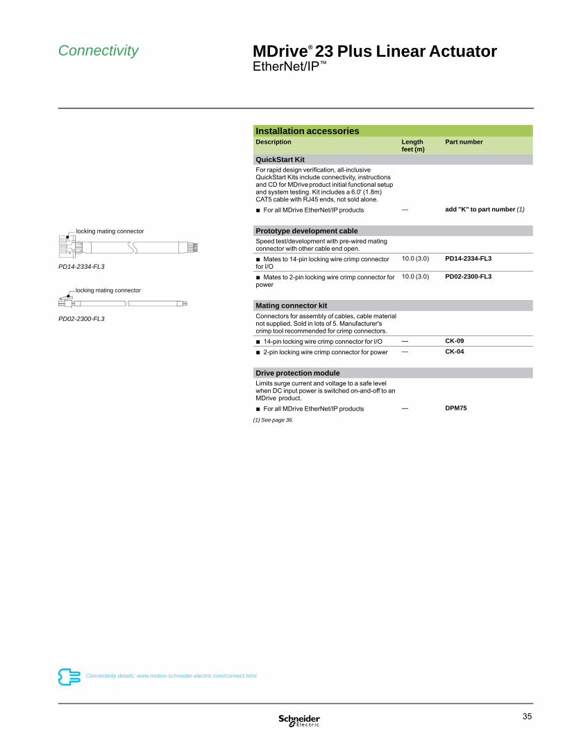
QuickStart KitFor rapid design verifi cation, all-inclusive QuickStart Kits include connectivity, instructions and CD for MDrive product initial functional setup and system testing. Kit includes a 6.0' (1.8m) CAT5 cable with RJ45 ends, not sold alone.■ For all MDrive EtherNet/IP products — add "K" to part number (1)
Prototype development cableSpeed test/development with pre-wired mating connector with other cable end open.■ Mates to 14-pin locking wire crimp connector for I/O
10.0 (3.0) PD14-2334-FL3
■ Mates to 2-pin locking wire crimp connector for power
10.0 (3.0) PD02-2300-FL3
Mating connector kitConnectors for assembly of cables, cable material not supplied. Sold in lots of 5. Manufacturer's crimp tool recommended for crimp connectors.■ 14-pin locking wire crimp connector for I/O — CK-09
■ 2-pin locking wire crimp connector for power — CK-04
Drive protection moduleLimits surge current and voltage to a safe level when DC input power is switched on-and-off to an MDrive product.■ For all MDrive EtherNet/IP products — DPM75
(1) See page 36.
PD14-2334-FL3
locking mating connector
PD02-2300-FL3
locking mating connector

36
External shaft style
Part numbers
Easy MDrive part numbers via an interactive tool at: www.motion.schneider-electric.com/MDriveLinear.html
MDrive® 23 Plus Linear ActuatorEtherNet/IP™
P2: CommunicationR = EtherNet/IP with RJ45 locking connector
P1: I/OC = 14-pin locking wire crimp connector
MDrive® 23 Plus
P3: Power2-pin locking wire crimp connector
Part numbersExample: K M L I 3 C I R 2 3 A 7 – EQ –
QuickStart KitK = kit option, or leave blank if unwanted
K M L I 3 C I R 2 3 A 7 – EQ –
MDrive Plus Linear Actuator versionMLI = EtherNet/IP
K M L I 3 C I R 2 3 A 7 – EQ –
Type3 = expanded features
K M L I 3 C I R 2 3 A 7 – EQ –
P1 connectorC = wire crimp
K M L I 3 C I R 2 3 A 7 – EQ –
CommunicationI = EtherNet/IP
K M L I 3 C I R 2 3 A 7 – EQ –
P2 connector R = RJ45
K M L I 3 C I R 2 3 A 7 – EQ –
Motor size23 = NEMA 23 (2.3" / 57 mm)
K M L I 3 C I R 2 3 A 7 – EQ –
Motor lengthA = single stack
K M L I 3 C I R 2 3 A 7 – EQ –
Drive voltage7 = +12 to +75 VDC
K M L I 3 C I R 2 3 A 7 – EQ –
EncoderLeave bank if not wanted – EQ = 512-line internal differential magnetic encoder with index mark
K M L I 3 C I R 2 3 A 7 – EQ –
Linear actuator specifi cationsComplete the part number from the table below –
Continued – Part numbersExample - linear actuator specifi cations: – L G 3 M 0 6 0 G T
Linear actuator– L
– L G 3 M 0 6 0 G T
Screw lead / pitchG = 0.375" / 9.525 mm travel per revA = 0.200" / 5.08 mm travel per revB = 0.167" / 4.233 mm travel per revD = 0.083" / 2.116 mm travel per rev
– L G 3 M 0 6 0 G T
Shaft style3 = External
– L G 3 M 0 6 0 G T
Screw end fi nishM = metric threadedU = UNC threadedS = smoothZ = none
– L G 3 M 0 6 0 G T
Screw length030 = 3.0" (77.5 mm) minimum up to240 = 24.0" (610.0 mm) maximum, in 0.1" (2.5 mm) increments
– L G 3 M 0 6 0 G T
Nut G = general purpose, only with External shaft products (1)A = anti-backlash, only with External shaft products (2)
– L G 3 M 0 6 0 G T
CoatingT = Tefl onZ = None
– L G 3 M 0 6 0 G T
(1) Dynamic load limit to 60 lbs / 22 kg.(2) Dynamic load limit to 25 lbs / 11 kg.

MDrive® Plus Linear ActuatorCANopen

38
MDrive® Plus Linear ActuatorCANopen
PresentationThe MDrive® Plus Linear Actuator with CANopen interface is an integrated product that combines a stepper motor linear actuator with mechanicals and electronics to form a single, compact system. It features a 1.8° 2-phase stepper motor linear actuator with on-board controller, drive electronics and optional encoder. Signals are converted directly from rotary to linear motion, eliminating the need for belts and pulleys, rack and pinion, hydraulics, pneumatics or other mechanical system.
CANopen firmware is provided for MDrive Plus Linear Actuator CANopen products, in addition to CANopen Tester GUI software for interface with the MD-CC500-000 CANopen dongle.
MDrive Plus Linear Actuator CANopen products support CiA DS301 and DSP402 Device Profile for Drives and Motion Control.
Application areasThe MDrive Plus Linear Actuator with CANopen interface is ideal for machine builders who want an optimized stepper motor linear actuator with on-board electronics. The integrated electronics of the MDrive product reduces the potential for problems due to electrical noise by eliminating the cable between motor and drive.
These compact, powerful and cost effective linear motion control solutions deliver exceptional smoothness and performance, and may reduce system cost, design and assembly time for a large range of applications.
Features
Standard Plus■ Highly integrated microstepping drive, controller, and high torque 1.8° 2-phase stepper motor linear actuator Non-captive or external shaft style Load limit up to 200 lbs Precision rolled lead screws■ Advanced current control for exceptional performance and smoothness■ Single supply: from +12 up to +75 VDC■ Cost effective■ Extremely compact■ 20 microstep resolutions to 51,200 steps/rev including: Degrees, Metric, Arc Minutes■ Auxiliary logic power supply input■ Open or optional closed loop control■ Programmable motor run and hold currents■ Four +5 to +24 VDC I/O lines accept sinking outputs, or sourcing or sinking inputs■ One 10 bit analog input selectable: 0 to +10 VDC, 0 to +5 VDC, 0-20 mA, 4-20 mA■ 0 to 5 MHz step clock rate selectable in 0.59 Hz increments■ CANopen communication■ Available options: Encoder Drive Protection Module■ Graphical user interface (GUI) provided for quick and easy configuration and programming via optional MD-CC500-000 communication converter
Expanded Plus2
■ +24 VDC tolerant I/O sourcing or sinking, inputs and outputs with up to 8 I/O lines and electronic gearing■ Closed loop control available with remote encoder option ■ High speed position capture input or trip output
Description
MDrive®Plus Linear Actuator with CANopennon-captive and external shaft styles

39
Standard Plus products Expanded Plus2 products (5)General purpose I/O Number 4 8 (4 with remote encoder option selected)
Type Sourcing or sinking inputs, or sinking outputs Sourcing or sinking outputs / inputsLogic range Inputs and outputs tolerant to +24 VDC,
inputs TTL level compatibleSourcing outputs +12 to +24 VDC, inputs and sinking outputs tolerant to +24 VDC, inputs TTL level compatible
Output sink current Up to 600 mA Up to 600 mAProtection Over temp, short circuit, transient, over voltage, inductive clamp
Motion Open loop confi guration
Number of settings 20Steps per revolution 200, 400, 800, 1000, 1600, 2000, 3200, 5000, 6400, 10000, 12800, 20000, 25000,
25600, 40000, 50000, 51200, 36000 (0.01 deg/μstep), 21600 (1 arc minute/μstep), 25400 (0.001mm/μstep)
Counters Type position, en cod er / 32 bitEdge rate maximum 5 MHz
Velocity Range +/- 5,000,000 steps per secondResolution 0.5961 steps per second
Accel / Decel Range 1.5 x 10⁹ steps per second2
Resolution 90.9 steps per second2
Electronic gearing
External clock in range (6) — 0.001 to 2.000Resolution / threshold — 32 bit resolution / TTL thresholdInput fi lter range — 50 nS to 12.9 μS (10 MHz to 38.8 kHz)Secondary clock out range (6) — 1 to 1
High speed I/O Position capture
Input fi lter range — 50 nS to 12.9 μS (10 MHz to 38.8 kHz)Resolution — 32 bit
Trip output – speed / resolution / threshold
— 150 nS / 32 bit / TTL
(1) Actual power supply current will depend on voltage and load.(2) Performance data for maximum force / load is based on a static load and will vary with a dynamic load.(3) Only applicable for External shaft linear actuator with anti-backlash nut.(4) When input voltage is removed, maintains power only to control and feedback circuits.(5) MDrive14 products available only as Plus2 versions.(6) Adjusting the microstep resolution can increase the range.
MDrive® Plus Linear ActuatorCANopen
Specifi cations
General specifi cationsMDrive 14 MDrive 17 MDrive 23
Input power Voltage VDC 12 to 48 12 to 48 12 to 75Current maximum (1) amp 1 2 2
Maximum thrust (2) Non-captive shaft lbs 50 50 200kg 22 22 91
External shaft withgeneral purpose nut
lbs 25 25 60kg 11 11 27
External shaft with anti-backlash nut
lbs 5 5 25kg 2 2 11
Maximum repeatability General purpose inch 0.005mm 0.127
Anti-backlash (3) inch 0.0005mm 0.0127
Thermal Operating temp non-condensing Heat sink – 40° to +85°CMotor – 40° to +100°C
Auxiliary logic input Voltage range (4) +12 to +24 VDC Analog input Resolution 10 bit
Voltage range 0 to +5 VDC, 0 to +10 VDC, 0-20 mA, 4-20 mACommunication Type CANopen CiA DS301 (V3.0), DSP402 (V2.0), 2.0B active
Baud rate Confi gurable 5 KB to 1 MbID 11 and / or 29 bitIsolation GalvanicFeatures Node guarding, heartbeat, SDOs, PDOs (variable mapping)
Software Setup parameters Storable to nonvolatile memoryTransmit PDOs 3 dynamically mappableReceive PDOs 3 dynamically mappableManufacturer specifi c objects I/O confi guration, run / hold currentModes of operation Profi le position, homing mode, profi le velocityInput functions General purpose, homing mode profi lesOutput functions General purpose
See User Manual for complete details: www.motion.schneider-electric.com/manuals.html

40
P2
MDrive® 14 Plus Linear ActuatorCANopen
– External shaft – mechanical specifi cations, dimensions in inches (mm)
– Non-captive shaft – mechanical specifi cations, dimensions in inches (mm)
Dimensions
2.05(52.07)
1.11(28.19)
0.079 ±0.01(2.0 ±0.25)
2.30(58.42)
0.25(6.35) 0.25
(6.35)
3.0 to 18.0(77.5 to 455.0)
P2
Ø 0.866 +0/-0.002(Ø 22.0 +0/-0.051)
1.4 ±0.004( 35.55 ±0.1)
4X M3x0.5 THREADx0.138 DEEP1.82
(46.19)
1.024( 26.0)
P1
0.425(10.8)
2.05(52.07)
1.11(28.19)
0.079 ±0.01(2.0 ±0.25)
2.30(58.42)
0.25(6.35)
0.25(6.35)
Nut
3.0 to 18.0(77.5 to 455.0)
P2
P2 connector
DB9 (male)
Communication
16-pin locking wire crimp connector
I/O & Power, Remote Encoder
P1
P1 connector
Unsupported loads and side loading are not recommended for non-captive shaft MDrive linear actuator products.
Loads for external shaft MDrive linear actuator products MUST BE supported. Side loading is not recommended.
Ø 0.866 +0/-0.002(Ø 22.0 +0/-0.051)
1.4 ±0.004( 35.55 ±0.1)
4X M3x0.5 THREADx0.138 DEEP1.82
(46.19)
1.024( 26.0)
P1
0.425(10.8)
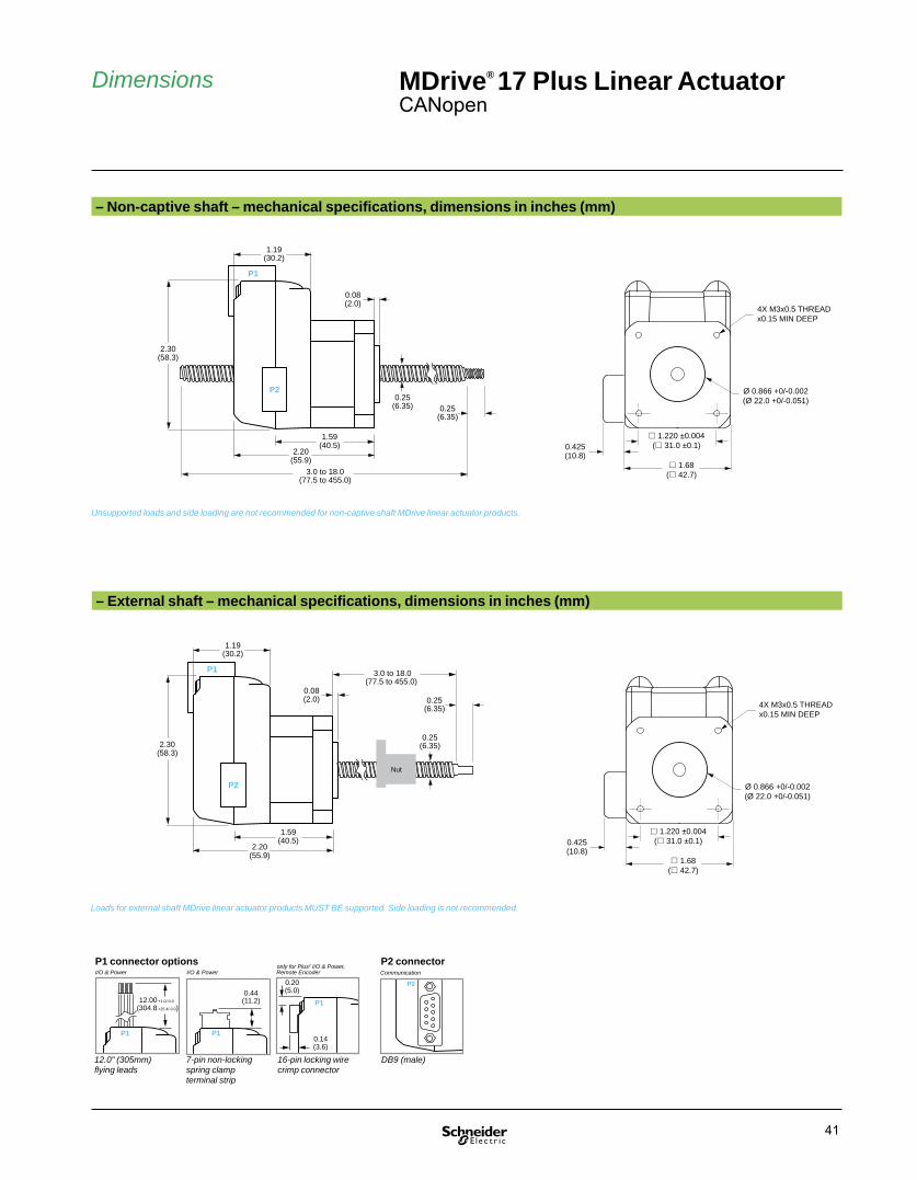
41
P2
– External shaft – mechanical specifi cations, dimensions in inches (mm)
– Non-captive shaft – mechanical specifi cations, dimensions in inches (mm)
MDrive® 17 Plus Linear ActuatorCANopen
Dimensions
Ø 0.866 +0/-0.002(Ø 22.0 +0/-0.051)
1.68( 42.7)
4X M3x0.5 THREADx0.15 MIN DEEP
1.220 ±0.004( 31.0 ±0.1)0.425
(10.8)
0.25(6.35)
P1
2.30(58.3)
1.19(30.2)
0.08(2.0)
P2
0.25(6.35)
2.20(55.9)
1.59(40.5)
3.0 to 18.0(77.5 to 455.0)
P1
2.30(58.3)
1.19(30.2)
0.08(2.0)
P2
2.20(55.9)
1.59(40.5)
0.25(6.35)
0.25(6.35)
Nut
3.0 to 18.0(77.5 to 455.0)
0.44(11.2)
P1
12.00 +1.0/-0.0 (304.8 +25.4/-0.0)
P1
0.20(5.0)
0.14(3.6)
P1
P1 connector options
7-pin non-locking spring clamp terminal strip
12.0" (305mm) fl ying leads
16-pin locking wire crimp connector
only for Plus2 I/O & Power,I/O & Power I/O & Power Remote Encoder
P2 connector
DB9 (male)
Communication
Unsupported loads and side loading are not recommended for non-captive shaft MDrive linear actuator products.
Loads for external shaft MDrive linear actuator products MUST BE supported. Side loading is not recommended.
Ø 0.866 +0/-0.002(Ø 22.0 +0/-0.051)
1.68( 42.7)
4X M3x0.5 THREADx0.15 MIN DEEP
1.220 ±0.004( 31.0 ±0.1)0.425
(10.8)

42
P2
– External shaft – mechanical specifi cations, dimensions in inches (mm)
– Non-captive shaft – mechanical specifi cations, dimensions in inches (mm)
1.90(48.3)
2.96(75.2)
0.06 ±0.00(1.5 ±0.1)
0.189 ±0.012(4.8 ±0.3)
1.34(34.0)
P2
P1/P3
2.65(67.31)
0.375(9.525)
3.0 to 24.0(77.5 to 610.0)
0.50(12.7)
MDrive® 23 Plus Linear ActuatorCANopen
Dimensions
2.02(51.2)
Ø 1.500 ±0.002(Ø 38.1 ±0.1)
2.22( 56.4)
Ø 0.197 +0.012/-0(Ø 5.0 +0.3/-0)
1.63(41.4)
1.856 ±0.008 ( 47.1 ±0.2) 0.425
(10.8)
1.90(48.3)
2.96(75.2)
0.06 ±0.00(1.5 ±0.1)
1.34(34.0)
P2
P1/P3
2.65(67.31)
0.19(4.9)
0.375(9.525)
0.50(12.7)
Nut
3.0 to 24.0(77.5 to 610.0)
P1/P30.38(9.7)
0.50(12.7)
0.13(3.3)
P1
0.44(11.2)
P1
12.00+1.0/-0.0
(304.8)(+25.4/-0.0)
P1 connector options
7-pin non-locking spring clamp terminal strip
12.0" (305mm) fl ying leads
14- & 2-pin locking wire crimp connectors
only for Plus2 P1: I/O, P3: Power, I/O & Power I/O & Power Remote Encoder
P2 connector
DB9 (male)
Communication
Unsupported loads and side loading are not recommended for non-captive shaft MDrive linear actuator products.
Loads for external shaft MDrive linear actuator products MUST BE supported. Side loading is not recommended.
2.02(51.2)
Ø 1.500 ±0.002(Ø 38.1 ±0.1)
2.22( 56.4)
Ø 0.197 +0.012/-0(Ø 5.0 +0.3/-0)
1.63(41.4)
1.856 ±0.008 ( 47.1 ±0.2) 0.425
(10.8)

43
Connectivity MDrive® 14 Plus Linear ActuatorCANopen
Installation accessoriesDescription Length
feet (m)Part number
Communication converterElectrically isolated, in-line con vert er pre-wired with mating connector to conveniently set/program communication parameters for a single MDrive Plus Linear Actuator via a PC's USB port.■ Mates to DB9 connector (1) 12.0 (3.6) MD-CC500-000
Prototype development cableSpeed test/development with pre-wired mating connector with other cable end open.■ Mates to 16-pin locking wire crimp connector for I/O, power and remote encoder option
10.0 (3.0) PD16-1417-FL3
Mating connector kitConnectors for assembly of cables, cable material not supplied. Sold in lots of 5. Manufacturer's crimp tool recommended for crimp connectors.■ 16-pin locking wire crimp connector for I/O, power and remote encoder option
— CK-10
Drive protection moduleLimits surge current and voltage to a safe level when DC input power is switched on-and-off to an MDrive.■ For all MDrive Linear Actuator products — DPM75
(1) Requires mating connector adapter and power supply, not supplied.
DB9M connector
USB connector
CAN +V
CAN -V(ground)
+7 to +30 VDCpower supply
12 termination resistor is required between CAN-H and CAN-L at MDrive® end of cable
DB9F
DB9F
Interface cable (not supplied)
CAN-HCAN-L
12
MD-CC500-000
PD16-1417-FL3
locking mating connector
Connectivity details: www.motion.schneider-electric.com/connect.html

44
MDrive® 17 Plus Linear ActuatorCANopen
Connectivity
Installation accessoriesDescription Length
feet (m)Part number
Communication converterElectrically isolated, in-line con vert er pre-wired with mating connector to conveniently set/program communication parameters for a single MDrive Plus Linear Actuator via a PC's USB port.■ Mates to DB9 connector (1) 12.0 (3.6) MD-CC500-000
Prototype development cableSpeed test/development with pre-wired mating connector with other cable end open.■ Mates to 16-pin locking wire crimp connector for I/O, power and remote encoder option
10.0 (3.0) PD16-1417-FL3
Mating connector kitConnectors for assembly of cables, cable material not supplied. Sold in lots of 5. Manufacturer's crimp tool recommended for crimp connectors.■ 16-pin locking wire crimp connector for I/O, power and remote encoder option
— CK-10
Drive protection moduleLimits surge current and voltage to a safe level when DC input power is switched on-and-off to an MDrive.■ For all MDrive Linear Actuator products — DPM75
(1) Requires mating connector adapter and power supply, not supplied.
MD-CC500-000
DB9M connector
USB connector
CAN +V
CAN -V(ground)
+7 to +30 VDCpower supply
12 termination resistor is required between CAN-H and CAN-L at MDrive® end of cable
DB9F
DB9F
Interface cable (not supplied)
CAN-HCAN-L
12
PD16-1417-FL3
locking mating connector
Connectivity details: www.motion.schneider-electric.com/connect.html

45
MDrive® 23 Plus Linear ActuatorCANopen
Connectivity
Installation accessoriesDescription Length
feet (m)Part number
Communication converterElectrically isolated, in-line con vert er pre-wired with mating connector to conveniently set/program communication parameters for a single MDrive Plus Linear Actuator via a PC's USB port.■ Mates to DB9 connector (1) 12.0 (3.6) MD-CC500-000
Prototype development cableSpeed test/development with pre-wired mating connector with other cable end open.■ Mates to 14-pin locking wire crimp connector for I/O and remote encoder option
10.0 (3.0) PD14-2334-FL3
■ Mates to 2-pin locking wire crimp connector for power
10.0 (3.0) PD02-2300-FL3
Mating connector kitConnectors for assembly of cables, cable material not supplied. Sold in lots of 5. Manufacturer's crimp tool recommended for crimp connectors.■ 14-pin locking wire crimp connector for I/O and remote encoder option
— CK-09
■ 2-pin locking wire crimp connector for power — CK-04
Drive protection moduleLimits surge current and voltage to a safe level when DC input power is switched on-and-off to an MDrive.■ For all MDrive Linear Actuator products — DPM75
(1) Requires mating connector adapter and power supply, not supplied.
MD-CC500-000
DB9M connector
USB connector
CAN +V
CAN -V(ground)
+7 to +30 VDCpower supply
12 termination resistor is required between CAN-H and CAN-L at MDrive® end of cable
DB9F
DB9F
Interface cable (not supplied)
CAN-HCAN-L
12
locking mating connector
PD02-2300-FL3
PD16-1417-FL3
locking mating connector
Connectivity details: www.motion.schneider-electric.com/connect.html

46
Part numbers MDrive® 14 Plus Linear ActuatorCANopen
MDrive® 14 Plus2
P2: CommunicationB = CANopen with DB9 male connector
P1: I/O & Power, and optional remote encoderC = 16-pin locking wire crimp connector
Part numbersExample: M L I 3 C C B 1 4 A 4 – EQ –
MDrive Plus Linear Actuator versionMLI = CANopen
M L I 3 C C B 1 4 A 4 – EQ –
Type3 = Plus2, expanded features
M L I 3 C C B 1 4 A 4 – EQ –
P1 connectorC = wire crimp
M L I 3 C C B 1 4 A 4 – EQ –
CommunicationC = CANopen
M L I 3 C C B 1 4 A 4 – EQ –
P2 connector B = DB9
M L I 3 C C B 1 4 A 4 – EQ –
Motor size14 = NEMA 14 (1.4" / 36 mm)
M L I 3 C C B 1 4 A 4 – EQ –
Motor lengthA = single stack
M L I 3 C C B 1 4 A 4 – EQ –
Drive voltage4 = +12 to +48 VDC
M L I 3 C C B 1 4 A 4 – EQ –
EncoderLeave blank if not wanted– EQ = internal encoder, 512-line internal magnetic encoder with index mark
– EQ –
Linear actuator specifi cationsComplete the part number from the table below –
Continued – Part numbersExample - linear actuator specifi cations: – L A 1 M 0 6 0 Z T
Linear actuator– L
– L A 1 M 0 6 0 Z T
Screw lead / pitchA = 0.250" / 6.35 mm travel per revB = 0.125" / 3.175 mm travel per revC = 0.063" / 1.588 mm travel per rev
– L A 1 M 0 6 0 Z T
Shaft style1 = Non-captive3 = External
– L A 1 M 0 6 0 Z T
Screw end fi nishM = metric threadedU = UNC threadedS = smoothZ = none
– L A 1 M 0 6 0 Z T
Screw length030 = 3.0" (77.5 mm) minimum up to180 = 18.0" (455.0 mm) maximum, in 0.1" (2.5 mm) increments
– L A 1 M 0 6 0 Z T
Nut Z = none, only with Non-captive shaft productsG = general purpose, only with External shaft products (1)A = anti-backlash, only with External shaft products (2)
– L A 1 M 0 6 0 Z T
CoatingT = Tefl onZ = None
– L A 1 M 0 6 0 Z T
(1) Dynamic load limit to 25 lbs / 11 kg.(2) Dynamic load limit to 5 lbs / 2 kg.
Non-captive shaft style External shaft style
Easy MDrive part numbers via an interactive tool at: www.motion.schneider-electric.com/MDriveLinear.html

47
MDrive® 17 Plus Linear ActuatorCANopen
Part numbers
MDrive® 17 Plus2
P2: CommunicationB = CANopen with DB9 male connector
P1: I/O & Power, andoptional remote encoderC = 16-pin locking wire crimp connector
MDrive® 17 Plus
P2: CommunicationB = CANopen with DB9 male connector
P1: I/O & PowerF = 12" flying leadsP = non-locking spring clamp terminal strip
Part numbersExample: M L I 1 F C B 1 7 A 4 – EQ –
MDrive Plus Linear Actuator versionMLI = CANopen
M L I 1 F C B 1 7 A 4 – EQ –
Type1 = Plus, standard features3 = Plus2, expanded features
M L I 1 F C B 1 7 A 4 – EQ –
P1 connectorF = fl ying leads (1)P = pluggable (1)C = wire crimp (2)
M L I 1 F C B 1 7 A 4 – EQ –
CommunicationC = CANopen
M L I 1 F C B 1 7 A 4 – EQ –
P2 connector B = DB9
M L I 1 F C B 1 7 A 4 – EQ –
Motor size17 = NEMA 17 (1.7" / 42 mm)
M L I 1 F C B 1 7 A 4 – EQ –
Motor lengthA = single stack
M L I 1 F C B 1 7 A 4 – EQ –
Drive voltage4 = +12 to +48 VDC
M L I 1 F C B 1 7 A 4 – EQ –
EncoderLeave blank if not wanted– EQ = internal encoder, 512-line internal magnetic encoder with index mark– EE = remote encoder interface, differential encoder to be provided by user (2)
– EQ –
Linear actuator specifi cationsComplete the part number from the table below –
Continued – Part numbersExample - linear actuator specifi cations: – L A 1 M 0 6 0 Z T
Linear actuator– L
– L A 1 M 0 6 0 Z T
Screw lead / pitchA = 0.250" / 6.35 mm travel per revB = 0.125" / 3.175 mm travel per revC = 0.063" / 1.588 mm travel per rev
– L A 1 M 0 6 0 Z T
Shaft style1 = Non-captive3 = External
– L A 1 M 0 6 0 Z T
Screw end fi nishM = metric threadedU = UNC threadedS = smoothZ = none
– L A 1 M 0 6 0 Z T
Screw length030 = 3.0" (77.5 mm) minimum up to180 = 18.0" (455.0 mm) maximum, in 0.1" (2.5 mm) increments
– L A 1 M 0 6 0 Z T
Nut Z = none, only with Non-captive shaft productsG = general purpose, only with External shaft products (3)A = anti-backlash, only with External shaft products (4)
– L A 1 M 0 6 0 Z T
CoatingT = Tefl onZ = None
– L A 1 M 0 6 0 Z T
(1) Only available with Plus products.(2) Only available with Plus2 products. (3) Dynamic load limit to 25 lbs / 11 kg.(4) Dynamic load limit to 5 lbs / 2 kg.
Non-captive shaft style External shaft style
Easy MDrive part numbers via an interactive tool at: www.motion.schneider-electric.com/MDriveLinear.html

48
MDrive® 23 Plus Linear ActuatorCANopen
Part numbers
MDrive® 23 Plus2
P2: CommunicationB = CANopen with DB9 male connector
P1: I/O, andoptional remote encoderC = 14-pin locking wire crimp connector
MDrive® 23 Plus
P2: CommunicationB = CANopen with DB9 male connector
P1: I/O & PowerF = 12" flying leadsP = non-locking spring clamp terminal strip
P3: Power2-pin locking wire crimp connector
Part numbersExample: M L I 1 F C B 2 3 A 7 – EQ –
MDrive Plus Linear Actuator versionMLI = CANopen
M L I 1 F C B 2 3 A 7 – EQ –
Type1 = Plus, standard features3 = Plus2, expanded features
M L I 1 F C B 2 3 A 7 – EQ –
P1 connectorF = fl ying leads (1)P = pluggable (1)C = wire crimp (2)
M L I 1 F C B 2 3 A 7 – EQ –
CommunicationC = CANopen
M L I 1 F C B 2 3 A 7 – EQ –
P2 connector B = DB9
M L I 1 F C B 2 3 A 7 – EQ –
Motor size23 = NEMA 23 (2.3" / 57 mm)
M L I 1 F C B 2 3 A 7 – EQ –
Motor lengthA = single stack
M L I 1 F C B 2 3 A 7 – EQ –
Drive voltage7 = +12 to +75 VDC
M L I 1 F C B 2 3 A 7 – EQ –
EncoderLeave blank if not wanted– EQ = internal encoder, 512-line internal magnetic encoder with index mark– EE = remote encoder interface, differential encoder to be provided by user (2)
– EQ –
Linear actuator specifi cationsComplete the part number from the table below –
Continued – Part numbersExample - linear actuator specifi cations: – L G 1 M 0 6 0 Z T
Linear actuator– L
– L G 1 M 0 6 0 Z T
Screw lead / pitchG = 0.375" / 9.525 mm travel per revA = 0.200" / 5.08 mm travel per revB = 0.167" / 4.233 mm travel per revD = 0.083" / 2.116 mm travel per rev
– L G 1 M 0 6 0 Z T
Shaft style1 = Non-captive3 = External
– L G 1 M 0 6 0 Z T
Screw end fi nishM = metric threadedU = UNC threadedS = smoothZ = none
– L G 1 M 0 6 0 Z T
Screw length030 = 3.0" (77.5 mm) minimum up to240 = 24.0" (610.0 mm) maximum, in 0.1" (2.5 mm) increments
– L G 1 M 0 6 0 Z T
Nut Z = none, only with Non-captive shaft productsG = general purpose, only with External shaft products (3)A = anti-backlash, only with External shaft products (4)
– L G 1 M 0 6 0 Z T
CoatingT = Tefl onZ = None
– L G 1 M 0 6 0 Z T
(1) Only available with Plus products. (2) Only available with Plus2 products. (3) Dynamic load limit to 60 lbs / 22 kg.(4) Dynamic load limit to 25 lbs / 11 kg.
Non-captive shaft style External shaft style
Easy MDrive part numbers via an interactive tool at: www.motion.schneider-electric.com/MDriveLinear.html

49
Combining the best servo and stepper motor features
MDrive Hybrid integrated linear systems can reduce size, cost and time-to-market for many applications — servo or stepper
Stepper motor maximumtorque rating
Green area represents motor torque performance range gain with HMT’s Variable Current Control
Standard stepper motorperformance range(design margin = 50% maximum torque as buffer against stalling)
Motor Speed
Tor
que
Hybrid Motion Technology™ MDrive Hybrid Linear Actuators feature Hybrid Motion Technology. HMT delivers smooth movement while eliminating unintentional stalling by never allowing the motor’s rotor and stator relationship to exceed the point synchronization is lost.
Torque ModeTorque mode, available in MDrive Hybrid products, regulates and maintains torque at a set level. This is a unique feature for stepper motors, and puts lower cost HMT systems on par with small to mid-size servo motors up to 2500 rpm.
Variable Current SettingMDrive Hybrid products can reduce energy consumption and lower operating costs with Variable Current Setting. This effi cient, energy-saving setting uses only the required current necessary to perform a task. Motor heat may also be lowered.
CompactnessMotor, mechanicals and electronics form a single, compact MDrive Hybrid unit with small footprint. This can dramatically reduce space requirements in an application.
SimplicityIntegration of motor, mechanicals and electronics reduces installation costs and the potential for problems due to electrical noise by eliminating the cable between motor and drive. User-friendly PC commissioning software simplifi es start-up.
Ease of integrationVersions include Step • Torque • Speed, Motion Control, Ethernet and CANopen. This open communication concept eases integration into existing system environments.
Use
100%of stepper motor’s maximum torque rating
Eliminate motor derating of up to
50%as buffer to avoid stalling in standard stepper motor systems

50
Hybrid Motion Technology™MDrive® Hybrid Linear Actuators, featuring Hybrid Motion Technology, deliver low cost motion solutions that can reduce system size, cost and time-to-market for many servo and stepper applications.
Hybrid Motion Technology™ (HMT) combines the best of servo and stepper motor technologies, while delivering unique capabilities and enhancements over both:
Hybrid Motion Technology is hardware based for real-time response. It continually monitors the relationship between a motor’s rotor and stator at sub-microsecond intervals, and will not allow that relationship to exceed the point where synchronization is lost. Delivering smooth movement while eliminating unintentional stalling, Hybrid Motion Technology will never lose functional control of the motor.
System benefi ts■ Quick reaction to large changes in loads without loss of synchronization■ No tuning required■ Higher inertia mismatch allowed■ High starting torque■ Smooth motion, even at extremely slow speeds■ Minimized impact of system resonance
Enhanced motor performance■ Real time closed loop control intervenes as required■ Eliminates loss of synchronization■ Allows full use of motor’s torque■ Never loses functional control of the motor■ Controllable motor torque via Torque Mode■ Variable current control applies only the current needed thereby reducing motor heating, lowering energy consumption and saving money
Applications■ Web tensioning■ Conveyors■ Bottle capping■ Medical automation■ Clamping■ Feeders■ Cut-to-length■ Form, fill and seal■ Package sorter■ Pick and place
Presentation
negatives• loss of synchronization/ stalling• 50% torque margin• post move corrections• constant torque/current• excessive heating
benefits• smooth motion• high torque at starting and low speed• cost effective• no tuning• stiffness at standstill
negatives• tuning required• higher price point• error driven• higher complexity• servo dither
benefits• peak torque• high speed• torque mode• closed loop
benefits• variable current/ torque• real time control• optimum torque at all speeds• lower energy use• eliminates loss of synchronization• never loses functional control of motor• reduced motor heating
HybridMotion Technology™
StepperMotor Technology
ServoMotor Technology
MDrive® Hybrid Linear ActuatorTechnology overview

MDrive® Hybrid Linear ActuatorStep • Torque • Speed

52
Description
MDrive®Hybrid Step•Torque•Speed Linear Actuator,non-captive and external shaft styles
PresentationThe MDrive® Hybrid Step • Torque • Speed Linear Actuator is a very compact, low cost linear motion system that includes a 1.8° 2-phase stepper motor linear actuator integrated with a high performance microstepping drive, performance enhancing Hybrid Motion Technology™ and internal encoder integral to system operation.
MDrive Hybrid systems use RS-422/485 communications. The MDrive Hybrid Step • Torque • Speed Linear Actuator systems can be confi gured to operate in one of four modes:■ Step — in Step / Direction mode, the MDrive Hybrid is controlled by an external step clock signal.■ Torque — in Torque Control mode, the MDrive Hybrid maintains a constant, preset torque output of the motor. The torque may be set in software, or controlled via the analog input using a 0 to +5 V, 0 to +10 V or -10 to +10 V signal.■ Speed — in Speed Control mode, the MDrive Hybrid operates as an intelligent speed control, with velocity being controlled via the analog input by a 0 to +5 V, 0 to +10 V or -10 to +10 V signal.■ Velocity — in Velocity Control mode, the MDrive Hybrid operates at a constant velocity commanded by the slew parameter.
MDrive Hybrid Step • Torque • Speed Linear Actuator system settings are via a supplied configuration GUI featuring:■ Easy installation via web interface■ Automatic communication configuration■ Tool-tips display valid range settings for each option
Application areasThe MDrive Hybrid Linear Actuator is ideal for machine builders who want a low cost linear motion alternative to servo motors and brushed DC motors. The highly compact all-in-one system converts signals directly from rotary to linear motion, eliminating the need for belts and pulleys, rack and pinion, hydraulics, pneumatics or other mechanical system.
Integrated electronics of the MDrive Hybrid Linear Actuator reduce the potential for problems due to electrical noise by eliminating the cable between motor and drive. This stepper-based linear actuator system requires no tuning, and provides real-time closed loop control through an internal encoder.
These compact, powerful and cost effective linear motion control solutions deliver exceptional smoothness and performance, and may reduce system cost, design and assembly time for a wide range of motor applications — both servo and stepper.
Features
■ Highly integrated microstepping drive and high torque 1.8° 2-phase stepper motor linear actuator Non-captive or external shaft style Load limit up to 200 lbs Precision rolled lead screws■ Hybrid Motion Technology™ control for exceptional performance■ Internal encoder, with signals available for external use■ RS-422/485 communication■ Single supply: +12 to +60 VDC■ Cost effective■ Extremely compact■ 20 microstep resolutions up to 51,200 steps per rev including: Degrees, Metric, Arc Minutes■ Available options: QuickStart Kit Drive Protection Module■ Graphical user interface provided for quick and easy parameter setup
MDrive® Hybrid Linear ActuatorStep • Torque • Speed

53
General specifi cationsMDrive 23
Input power Voltage VDC 12 to 60Current max (1) amp 3.5
Maximum thrust (2) Non-captive shaft
lbs 200kg 91
External shaft with general purpose nut
lbs 60
kg 27
External shaft with anti-backlash nut
lbs 25
kg 11
Maximum repeatability General purpose
inch 0.005mm 0.127
Anti-backlash (3)
inch 0.0005mm 0.0127
Thermal Operating temp non-condensing
Heat sink – 40° to +85°CMotor – 40° to +100°C
Isolated input Voltage range +5 to +24 VDC sourcing or sinkingMotion Digital fi lter range 50 nS to 12.9 μS (10 MHz to 38.8 kHz)
Clock types (Step mode)
Step / direction, quadrature, step up / step down
Step frequency 5 MHz maximum100 ns minimum pulse width
Microstep resolution
Number of settings 20Steps per revolution
Binary 200, 400, 800, 1600, 3200, 6400, 12800, 25600, 51200, 36000 (0.01 deg/μstep), 21600 (1 arc minute/μstep), 25400 (0.001 mm/μstep)
Decimal 1000, 2000, 5000, 10000, 20000, 25000, 40000, 50000Closed loop confi guration
Internal magnetic encoder line counts
100, 200, 250, 256, 400, 500, 512, 1000
Specifi cations
Setup parameters overview (4)Description
Operating modes Step & Direction For point-to-point positioning, clock types: step / direction, quadrature, step up / step downTorque Control Operates in relation to an analog input for positioning to torque setting
Resolution: 0 – 100%Accuracy, to scale: ± 5%
Speed Control Operates as an independent velocity control device, no external controller requiredHybrid Motion Technology™ settings
Setup / confi guration Turn HMT off / on in fi xed or variable mode; set and confi rm encoder line countOperation Set control bounds for motor torque and speed, lead, lag, and make-up of lost stepsHybrid Motion Technology status Display status alerts of 8 pre-programmed fi elds, read-onlyCalibration To maintain synchronization, select options for motor’s rotor-to-stator physical position
General settings Analog Enable activeCommunication Set baud rate; enable / disable party mode and features; Check Sum integrity quality assuranceI/O Clock and fi lter settings; Attention Output with 11 pre-programmed fi elds to select amongMotion Set various motion settings which vary with the operating mode selected, ex. Current, MSEL
The Speed Control Mode also includes settings for acceleration, deceleration, velocity and fl agsDefaults Restore system defaults or previously stored settings; view current communication settings
(1) Actual power supply current will depend on voltage and load.(2) Performance data for maximum force/load is based on a static load and will vary with a dynamic load.(3) Only applicable for External shaft linear actuator with anti-backlash nut.(4) All parameters are set using the supplied system confi guration GUI. Available settings vary with operating mode. An optional Communication Converter is recommended with fi rst orders.
See User Manual for complete details: www.motion.schneider-electric.com/manuals.html
MDrive® 23 Hybrid Linear ActuatorStep • Torque • Speed

54
P1
0.36(9.1)
I/O & Power
Dimensions
P1 connector
12-pin locking wire crimp connector
10-pin friction lock wire crimp connector
Communication
– External shaft – mechanical specifi cations, dimensions in inches (mm)
– Non-captive shaft – mechanical specifi cations, dimensions in inches (mm)
1.90(48.3)
2.96(75.2)
0.06 ±0.00(1.5 ±0.1)
0.189 ±0.012(4.8 ±0.3)
1.34(34.0)
P2
P1
2.65(67.31)
0.375(9.525)
3.0 to 24.0(77.5 to 610.0)
0.50(12.7)
2.02(51.2)
Ø 1.500 ±0.002(Ø 38.1 ±0.1)
2.22( 56.4)
Ø 0.197 +0.012/-0(Ø 5.0 +0.3/-0)
1.63(41.4)
1.856 ±0.008 ( 47.1 ±0.2)
P3
1.90(48.3)
2.96(75.2)
0.06 ±0.00(1.5 ±0.1)
1.34(34.0)
P2
P1
2.65(67.31)
0.19(4.9)
0.375(9.525)
0.50(12.7)
Nut
3.0 to 24.0(77.5 to 610.0)
2.02(51.2)
Ø 1.500 ±0.002(Ø 38.1 ±0.1)
2.22( 56.4)
Ø 0.197 +0.012/-0(Ø 5.0 +0.3/-0)
1.63(41.4)
1.856 ±0.008 ( 47.1 ±0.2)
P3
Unsupported loads and side loading are not recommended for non-captive shaft MDrive linear actuator products.
Loads for external shaft MDrive linear actuator products MUST BE supported. Side loading is not recommended.
P3
P3 connector
10-pin locking wire crimp connector
Encoder
P2
P2 connector
MDrive® 23 Hybrid Linear ActuatorStep • Torque • Speed

55
Connectivity
Installation accessoriesDescription Length
feet (m)Part number
QuickStart KitFor rapid design verifi cation, all-inclusive QuickStart Kits include connectivity, instructions and CD for MDrive Hybrid Linear Actuator initial functional setup and system testing.■ For MDrive 23 Hybrid Step • Torque • Speed systems
— add "K" to part number (1)
Communication converterElectrically isolated, in-line con vert er pre-wired with mating connector to conveniently set/program communication parameters for a single MDrive Hybrid Linear Actuator via a PC's USB port.■ Mates to 10-pin friction lock wire crimp connector
12.0 (3.6) MD-CC402-001
Prototype development cableSpeed test/development with pre-wired mating connector with other cable end open.■ Mates to 12-pin locking wire crimp connector for I/O and power
10.0 (3.0) PD12-1434-FL3
■ Mates to 10-pin friction lock wire crimp connector for communication
10.0 (3.0) PD10-1434-FL3
■ Mates to 10-pin locking wire crimp connector for encoder
6.0 (1.8) ED-CABLE-JST10
Mating connector kitConnectors for assembly of cables, cable material not supplied. Sold in lots of 5. Manufacturer's crimp tool recommended for crimp connectors.■ 12-pin locking wire crimp connector for I/O and power
— CK-03
■ 10-pin friction lock wire crimp connector for communication
— CK-02
■ 10-pin locking wire crimp connector for encoder
— CK-13
Drive protection moduleLimits surge current and voltage to a safe level when DC input power is switched on-and-off to an MDrive product.■ For all MDrive Linear Actuator systems — DPM75
(1) See page 56.
locking mating connector
PD12-1434-FL3
USB connector
in-line converter
MDrive® Hybrid 10-pin friction lockmating connector
MD-CC402-001
PD10-1434-FL3
friction lock mating connector
ED-CABLE-JST10
locking mating connector
Connectivity details: www.motion.schneider-electric.com/connect.html
MDrive® 23 Hybrid Linear ActuatorStep • Torque • Speed

56
Part numbers
P2: CommunicationL = RS-422/485 10-pin friction lock wire crimp connector
P1: I/O & PowerC = 12-pin locking wire crimp connector
MDrive® 23 Hybrid
P3: Encoder10-pin locking wire crimp connector(not visible)
Part numbersExample: K M A M 3 C R L 2 3 A 6 – EAM –
QuickStart KitK = kit option, or leave blank if not wanted
K M A M 3 C R L 2 3 A 6 – EAM –
MDrive Hybrid Linear Actuator versionMAM = Step•Torque•Speed
K M A M 3 C R L 2 3 A 6 – EAM –
Type3 = Hybrid Motion Technology
K M A M 3 C R L 2 3 A 6 – EAM –
P1 connectorC = wire crimp
K M A M 3 C R L 2 3 A 6 – EAM –
CommunicationR = RS-422/485
K M A M 3 C R L 2 3 A 6 – EAM –
P2 connector L = wire crimp
K M A M 3 C R L 2 3 A 6 – EAM –
Motor size23 = NEMA 23 (2.3" / 57 mm)
K M A M 3 C R L 2 3 A 6 – EAM –
Motor lengthA = single stack
K M A M 3 C R L 2 3 A 6 – EAM –
Drive voltage6 = +12 to +60 VDC
K M A M 3 C R L 2 3 A 6 – EAM –
Encoder, differentialinternal magnetic encoder with index mark, signals available for external use– EAM = 100 line count– EBM = 200 line count– ECM = 250 line count– EWM = 256 line count– EDM = 400 line count– EHM = 500 line count– EXM = 512 line count– EJM = 1000 line count
K M A M 3 C R L 2 3 A 6 – EAM –
Linear actuator specifi cationsComplete the part number from the table below –
Continued – Part numbersExample - linear actuator specifi cations: – L G 1 M 0 6 0 Z T
Linear actuator– L
– L G 1 M 0 6 0 Z T
Screw lead / pitchG = 0.375" / 9.525 mm travel per revA = 0.200" / 5.08 mm travel per revB = 0.167" / 4.233 mm travel per revD = 0.083" / 2.116 mm travel per rev
– L G 1 M 0 6 0 Z T
Shaft style1 = Non-captive3 = External
– L G 1 M 0 6 0 Z T
Screw end fi nishM = metric threadedU = UNC threadedS = smoothZ = none
– L G 1 M 0 6 0 Z T
Screw length030 = 3.0" (77.5 mm) minimum up to240 = 24.0" (610.0 mm) maximum, in 0.1" (2.5 mm) increments
– L G 1 M 0 6 0 Z T
Nut Z = none, only with Non-captive shaft productsG = general purpose, only with External shaft products (1)A = anti-backlash, only with External shaft products (2)
– L G 1 M 0 6 0 Z T
CoatingT = Tefl onZ = None
– L G 1 M 0 6 0 Z T
(1) Dynamic load limit to 60 lbs / 22 kg.(2) Dynamic load limit to 25 lbs / 11 kg.
Non-captive shaft style External shaft style
Easy MDrive part numbers via an interactive tool at: www.motion.schneider-electric.com/MDriveLinear.html
MDrive® 23 Hybrid Linear ActuatorStep • Torque • Speed

MDrive® Hybrid Linear ActuatorMotion Control

58
PresentationThe MDrive® Hybrid Motion Control Linear Actuator is a very compact linear motion system that includes a 1.8° 2-phase stepper motor linear actuator with on-board fully programmable motion controller, high performance microstepping drive, performance enhancing Hybrid Motion Technology™ and internal encoder integral to system operation. These stand-alone motion control solutions can be used without any external controller.
With MDrive Hybrid integrated motion control systems, point-to-point positioning, torque mode and velocity control are all user programmed with pre-installed MCode software, a simple language that uses 1 to 2 character instructions, and an easy-to-use terminal emulator program provided. MDrive products come standard with RS-422/485 serial interface.
ModbusTCP protocol, per specification Version 1.1b, is available as an option. These products operate in immediate mode, not as programmable products. Communication may also be via MCode/TCP, a version of the MCode instruction set used for RS-422/485 serial communication products, adapted to utilize TCP/IP message format-ting. For EtherNet/IP systems, including ModbusTCP, separate MDrive EtherNet/IP products are available.
Application areasThe MDrive Hybrid Linear Actuator is ideal for machine builders who want a low cost linear motion alternative to servo motors and brushed DC motors. The highly compact all-in-one system converts signals directly from rotary to linear motion, eliminating the need for belts and pulleys, rack and pinion, hydraulics, pneumatics or other mechanical system.
Integrated electronics of the MDrive Hybrid Linear Actuator reduce the potential for problems due to electrical noise by eliminating the cable between motor and drive. This stepper-based linear actuator system requires no tuning, and provides real-time closed loop control through an internal encoder.
These compact, powerful and cost effective linear motion control solutions deliver exceptional smoothness and performance, and may reduce system cost, design and assembly time for a wide range of motor applications — both servo and stepper.
Features
■ Highly integrated microstepping drive and high torque 1.8° 2-phase stepper motor linear actuator Non-captive or external shaft style Load limit up to 200 lbs Precision rolled lead screws■ Fully programmable motion controller ■ Hybrid Motion Technology™ control for exceptional performance■ Internal encoder■ RS-422/485 communication or ModbusTCP protocol■ Single supply: +12 to +60■ Cost effective■ Extremely compact■ 20 microstep resolutions up to 51,200 steps per rev including: Degrees, Metric, Arc Minutes■ Available options: QuickStart Kit Drive Protection Module■ Graphical user interface provided for quick and easy configuration and programming
Description
MDrive®Hybrid Motion Control Linear Actuator, fully programmable, non-captive and external shaft styles
MDrive® Hybrid Linear ActuatorMotion Controlfully programmable

59
Specifi cations
General specifi cationsMDrive 23
Input power Voltage VDC 12 to 60Current maximum (1) amp 3.5
Maximum thrust (2) Non-captive shaft lbs 200kg 91
External shaft withgeneral purpose nut
lbs 60kg 27
External shaft with anti-backlash nut
lbs 25kg 11
Maximum repeatability General purpose inch 0.005mm 0.127
Anti-backlash (3) inch 0.0005mm 0.0127
Thermal Operating temp non-condensing Heat sink – 40° to +85°CMotor – 40° to +100°C
Auxiliary logic input Voltage range (4) +12 to +24 VDC Analog input Resolution 10 bit
Voltage range 0 to +5 VDC, 0 to +10 VDC, 0-20 mA, 4-20 mACommunication Type RS-422/485 or ModbusTCP
Baud rate 4.8 to 115.2 kbps (5)Software Program storage Type / size fl ash / 6384 bytes
User registers Four 32 bitUser program labels & variables 192Math functions +, –, ×, ÷, >, <, =, <=, >=, AND, OR, XOR, NOTBranch functions Branch and CallGeneral purpose I/O functions Inputs home, limit plus, limit minus, go, stop, pause, jog plus, jog minus, general purpose
Outputs moving, fault, stall, velocity change, general purposeTrip functions Trip on input, trip on position, trip on time, trip capture, trip on relative positionParty mode addresses 62 (5)Encoder functions Find index
General purpose I/O Number 8 (or 4 with ModbusTCP protocol)Type Sourcing or sinking outputs / inputsLogic range Sourcing outputs +12 to +24 VDC
Inputs and sinking outputs tolerant to +24 VDC, inputs TTL level compatibleOutput sink / source current Up to 600 mA per channelProtection Over temp, short circuit, transient, over voltage, inductive clamp
Motion Closed loop confi guration with encoder
Encoder type Internal, magneticSteps per rev 51200Resolution 1000 lines / 4000 edges per rev
Counters Type Position, encoder / 32 bitEdge rate max 5 MHz
Velocity Range +/– 5,000,000 steps per secondResolution 0.5961 steps per second
Accel / Decel Range 1.5 x 10⁹ steps per second2
Resolution 90.9 steps per second2 High speed I/O Position capture Input fi lter range 50 nS to 12.9 μS (10 MHz to 38.8 kHz)
Resolution 32 bitTrip output – speed/resolution/threshold 150 nS / 32 bit / TTL
(1) Actual power supply current will depend on voltage and load.(2) Performance data for maximum force / load is based on a static load and will vary with a dynamic load.(3) Only applicable for External shaft linear actuator with anti-backlash nut.(4) When input voltage is removed, maintains power only to control and feedback circuits.(5) Only with RS-422/485 systems. All parameters are set using the supplied system confi guration GUI. An optional Communication Converter is recommended with fi rst orders.
See User Manual for complete details: www.motion.schneider-electric.com/manuals.html
MDrive® 23 Hybrid Linear ActuatorMotion Controlfully programmable
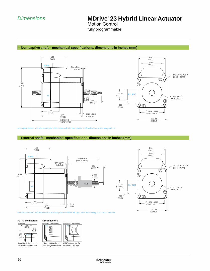
60
2.02(51.2)
Ø 1.500 ±0.002(Ø 38.1 ±0.1)
2.22( 56.4)
Ø 0.197 +0.012/-0(Ø 5.0 +0.3/-0)
1.63(41.4)
1.856 ±0.008 ( 47.1 ±0.2)
0.93( 23.6)
0.86(21.8)
P2: RJ45
– External shaft – mechanical specifi cations, dimensions in inches (mm)
– Non-captive shaft – mechanical specifi cations, dimensions in inches (mm)
2.02(51.2)
Ø 1.500 ±0.002(Ø 38.1 ±0.1)
2.22( 56.4)
Ø 0.197 +0.012/-0(Ø 5.0 +0.3/-0)
1.63(41.4)
1.856 ±0.008 ( 47.1 ±0.2)
0.93( 23.6)
0.86(21.8)
P2: RJ45
1.90(48.3)
2.96(75.2)
0.06 ±0.00(1.5 ±0.1)
0.189 ±0.012(4.8 ±0.3)
1.34(34.0)
P2
P1/P3
2.65(67.31)
0.375(9.525)
3.0 to 24.0(77.5 to 610.0)
0.50(12.7)
Dimensions
1.90(48.3)
2.96(75.2)
0.06 ±0.00(1.5 ±0.1)
1.34(34.0)
P2
P1/P3
2.65(67.31)
0.19(4.9)
0.375(9.525)
0.50(12.7)
Nut
3.0 to 24.0(77.5 to 610.0)
P2
P1/P30.38(9.7)
0.50(12.7)
0.13(3.3)
P1 / P3 connectors
14- & 2-pin locking wire crimp connectors
I/O & Power
P2 connectors
10-pin friction lock wire crimp connector
P2
RJ45 connector forModbusTCP only
Unsupported loads and side loading are not recommended for non-captive shaft MDrive linear actuator products.
Loads for external shaft MDrive linear actuator products MUST BE supported. Side loading is not recommended.
RS-422/485 Communication ModbusTCP Communication
MDrive® 23 Hybrid Linear ActuatorMotion Controlfully programmable

61
Connectivity
PD14-2334-FL3
locking mating connector
PD02-2300-FL3
locking mating connector
Installation accessoriesDescription Length
feet (m)Part number
QuickStart KitFor rapid design verifi cation, all-inclusive QuickStart Kits include connectivity, instructions and CD for MDrive Hybrid Linear Actuator initial functional setup and system testing.■ For MDrive 23 Hybrid Motion Control systems — add "K" to part number (1)
Communication converterElectrically isolated, in-line con vert er pre-wired with mating connector to conveniently set/program communication parameters for a single MDrive Hybrid Linear Actuator via a PC's USB port.■ Mates to 10-pin friction lock wire crimp connector
12.0 (3.6) MD-CC402-001
Prototype development cableSpeed test/development with pre-wired mating connector with other cable end open.■ Mates to 14-pin locking wire crimp connector for I/O
10.0 (3.0) PD14-2334-FL3
■ Mates to 10-pin friction lock wire crimp connector for communication
10.0 (3.0) PD10-1434-FL3
■ Mates to 2-pin locking wire crimp connector for power
10.0 (3.0) PD02-2300-FL3
Mating connector kitConnectors for assembly of cables, cable material not supplied. Sold in lots of 5. Manufacturer's crimp tool recommended for crimp connectors.■ 14-pin locking wire crimp connector for I/O — CK-09
■ 10-pin friction lock wire crimp connector for communication
— CK-02
■ 2-pin locking wire crimp connector for power — CK-04
Drive protection moduleLimits surge current and voltage to a safe level when DC input power is switched on-and-off to an MDrive product.■ For all MDrive Linear Actuator systems — DPM75
(1) See page 62.
PD10-1434-FL3
friction lock mating connector
USB connector
in-line converter
MDrive® Hybrid 10-pin friction lockmating connector
MD-CC402-001
Connectivity details: www.motion.schneider-electric.com/connect.html
MDrive® 23 Hybrid Linear ActuatorMotion Controlfully programmable

62
P2: CommunicationL = RS-422/485 with 10-pin friction lock wire crimp connectorR = ModbusTCP with RJ45 locking connector
P1: I/OC = 14-pin locking wire crimp connector
MDrive® 23 Hybrid
P3: Power2-pin locking wire crimp connector
Part numbers
Part numbersExample: K M A I 3 C R L 2 3 A 6 – EJM –
QuickStart KitK = kit option, or leave blank if not wanted
K M A I 3 C R L 2 3 A 6 – EJM –
MDrive Hybrid Linear Actuator versionMAI = Motion Control
K M A I 3 C R L 2 3 A 6 – EJM –
Type3 = Hybrid Motion Technology
K M A I 3 C R L 2 3 A 6 – EJM –
P1 connectorC = wire crimp
K M A I 3 C R L 2 3 A 6 – EJM –
CommunicationR = RS-422/485E = ModbusTCP
K M A I 3 C R L 2 3 A 6 – EJM –
P2 connector L = wire crimpR = RJ45 (1)
K M A I 3 C R L 2 3 A 6 – EJM –
Motor size23 = NEMA 23 (2.3" / 57 mm)
K M A I 3 C R L 2 3 A 6 – EJM –
Motor lengthA = single stack
K M A I 3 C R L 2 3 A 6 – EJM –
Drive voltage6 = +12 to +60 VDC
K M A I 3 C R L 2 3 A 6 – EJM –
Encoder– EJM = 1000-line internal encoder
K M A I 3 C R L 2 3 A 6 – EJM –
Linear actuator specifi cationsComplete the part number from the table below –
Continued – Part numbersExample - linear actuator specifi cations: – L G 1 M 0 6 0 Z T
Linear actuator– L
– L G 1 M 0 6 0 Z T
Screw lead / pitchG = 0.375" / 9.525 mm travel per revA = 0.200" / 5.08 mm travel per revB = 0.167" / 4.233 mm travel per revD = 0.083" / 2.116 mm travel per rev
– L G 1 M 0 6 0 Z T
Shaft style1 = Non-captive3 = External
– L G 1 M 0 6 0 Z T
Screw end fi nishM = metric threadedU = UNC threadedS = smoothZ = none
– L G 1 M 0 6 0 Z T
Screw length030 = 3.0" (77.5 mm) minimum up to240 = 24.0" (610.0 mm) maximum, in 0.1" (2.5 mm) increments
– L G 1 M 0 6 0 Z T
Nut Z = none, only with Non-captive shaft productsG = general purpose, only with External shaft products (2)A = anti-backlash, only with External shaft products (3)
– L G 1 M 0 6 0 Z T
CoatingT = Tefl onZ = None
– L G 1 M 0 6 0 Z T
(1) Only available with products with ModbusTCP protocol.(2) Dynamic load limit to 60 lbs / 22 kg.(3) Dynamic load limit to 25 lbs / 11 kg.
Non-captive shaft style External shaft style
Easy MDrive part numbers via an interactive tool at: www.motion.schneider-electric.com/MDriveLinear.html
MDrive® 23 Hybrid Linear ActuatorMotion Controlfully programmable

MDrive® Hybrid Linear ActuatorEtherNet/IP

64
MDrive®Hybrid EtherNet/IP Linear Actuator, non-captive and external shaft styles
PresentationThe MDrive® Hybrid EtherNet/IP™ Linear Actuator is a very compact, low cost linear motion system that includes a 1.8° 2-phase stepper motor linear actuator with on-board motion controller, microstepping drive, internal encoder integral to system operation, and Hybrid Motion Technology™. HMT combines the best of servo and stepper motor technologies, while delivering unique capabilities and enhancements over both including: real time closed loop control no loss of synchronization full use of motor torque torque mode control reduced motor heat (1) lower energy consumption (1)MDrive EtherNet/IP products are ODVA™ compliant and interface with many manufacturer's systems, including Rockwell, Omron and Schneider Electric.
MDrive EtherNet/IP Linear Actuators are adapter class devices, capable of explicit or implicit messaging, with a configuration port for setting the IP address. To set parameters and assembly object mapping, a Windows-based TCP/IP Configuration Utility is provided.
MDrive® Plus EtherNet/IP™ Linear Actuators also support ModbusTCP protocol, per specification Version 1.1b. Operation is in immediate mode, not as programmable products. Communication may also be via MCode/TCP, a version of the MCode instruction set used for RS-422/485 serial communication products, adapted to utilize TCP/IP message formatting.
Confi guration utilityMDrive EtherNet/IP products have a configuration port provided for setting the IP address. Windows-based TCP/IP Configuration Utility sets parameters and assembly object mapping.
Application areasThe MDrive EtherNet/IP product is ideal for machine builders who want an optimized motor with on-board electronics and support for the widely used Ethernet industrial protocol. MDrive products are compact motion control solutions that can reduce system cost, design and assembly time for a wide range of motor applications – both servo and stepper.
Features
■ Highly integrated microstepping drive, motion controller and high torque NEMA 23 1.8° 2-phase stepper motor linear actuator Non-captive and external shaft styles Load limit up to 200 lbs Precision rolled lead screws■ Hybrid Motion Technology with integral internal encoder ■ Four +5 to +24 VDC I/O lines accept sourcing or sinking inputs or outputs■ Single supply: +12 to +60 VDC■ ODVA compliant EtherNet/IP industrial protocol■ Standard TCP/IP stack with virtually unlimited nodes■ Dynamic mapping of assembly object■ Explicit and implicit messaging■ Cost effective■ Extremely compact■ 20 microstep resolutions to 51,200 steps/rev including: Degrees, Metric, Arc Minutes■ Auxiliary logic power supply input■ Open or closed loop control■ Programmable motor run and hold currents■ High speed position capture input or trip output■ One 10 bit analog input selectable: 0 to +10 VDC, 0 to +5 VDC, 0-20 mA, 4-20 mA■ 0 to 5 MHz step clock rate selectable in 0.59 Hz increments■ GUI provided for quick and easy configuration
(1) Achieved with Hybrid Motion Technology variable current control.
Description MDrive® Hybrid Linear ActuatorEtherNet/IP™

65
Specifi cations
See User Manual for complete details: www.motion.schneider-electric.com/manuals.html
MDrive® 23 Hybrid Linear ActuatorEtherNet/IP™
General specifi cationsMDrive 23
Input power Voltage VDC 12 to 60Current maximum (1) amp 3.5
Maximum thrust (2) Non-captive shaft lbs 200kg 91
External shaft with general purpose nut
lbs 60kg 27
External shaft with anti-backlash nut
lbs 25kg 11
Maximum repeatability General purpose inch 0.005mm 0.127
Anti-backlash (3) inch 0.0005mm 0.0127
Thermal Operating temp non-condensing
Heat sink °C – 40 to + 85Motor °C – 40 to +100
Auxiliary logic input Voltage range (4) VDC +12 to +24Analog input Resolution 10 bit
Voltage range 0 to +5 VDC, 0 to +10 VDC, 0-20 mA, 4-20 mAGeneral purpose I/O Number 4
Type Sourcing or sinking outputs/inputsLogic range Sourcing outputs +12 to 24 VDC, inputs&sinking outputs tolerant to
+24 VDC, inputs TTL level compatibleOutput sink/source current Up to 600 mAProtection Over temp, short circuit, transient, over voltage, inductive clamp
Communication Type Ethernet TCP/IPProtocols EtherNet/IP (ODVA compliant)
ModbusTCPMCode/TCP on confi guration port
Baud rate 100 MbpsConfi guration port 503
Motion Open loop confi guration Number of settings 20Steps per revolution 200, 400, 800, 1000, 1600, 2000, 3200, 5000, 6400, 10000,
12800, 20000, 25000, 25600, 40000, 50000, 51200, 36000 (0.01 deg/μstep), 21600 (1 arc minute/μstep), 25400 (0.001mm/μstep)
Counters Type Position, en cod er / 32 bitEdge rate maximum 5 MHz
Closed loop confi guration Steps per revolution 1000 lines / 4000 edges per revEncoder Differential magnetic
Electronic gearing unavailableHigh speed I/O Position capture Input fi lter range 50 nS to 12.9 μS (10 MHz to 38.8 kHz)
Resolution 32 bitTrip output Speed 150 nS
Resolution 32 bitThreshold TTL
Velocity Range +/- 5,000,000 steps per secondResolution 0.5961 steps per second
Accel / Decel Range 1.5 x 10⁹ steps per second2
Resolution 90.9 steps per second2
EtherNet/IP Device class AdapterMessage types Explicit or implicitAssembly object 0x04 Output (TO) Instance 100
Output (OT) Instance 112Mapping to MCode Dynamic
Device profi le Object types Identity, Assembly, TCP, Ethernet link, Manufacturer specifi c(1) Actual power supply current will depend on voltage and load.(2) Performance data for maximum force / load is based on a static load and will vary with a dynamic load.(3) Only applicable for External shaft linear actuator with anti-backlash nut.(4) When input voltage is removed, maintains power only to control and feedback circuits.(5) Adjusting the microstep resolution can increase the range.

66
Dimensions MDrive® 23 Hybrid Linear ActuatorEtherNet/IP™
Unsupported loads and side loading are not recommended for non-captive shaft MDrive linear actuator products.
– External shaft – mechanical specifi cations, dimensions in inches (mm)
– Non-captive shaft – mechanical specifi cations, dimensions in inches (mm)
2.02(51.2)
Ø 1.500 ±0.002(Ø 38.1 ±0.1)
2.22( 56.4)
Ø 0.197 +0.012/-0(Ø 5.0 +0.3/-0)
1.63(41.4)
1.856 ±0.008 ( 47.1 ±0.2)
0.93( 23.6)
0.86(21.8)
P2: RJ45
2.02(51.2)
Ø 1.500 ±0.002(Ø 38.1 ±0.1)
2.22( 56.4)
Ø 0.197 +0.012/-0(Ø 5.0 +0.3/-0)
1.63(41.4)
1.856 ±0.008 ( 47.1 ±0.2)
0.93( 23.6)
0.86(21.8)
P2: RJ45
1.90(48.3)
2.96(75.2)
0.06 ±0.00(1.5 ±0.1)
0.189 ±0.012(4.8 ±0.3)
1.34(34.0)
P1/P3
2.65(67.31)
0.375(9.525)
3.0 to 24.0(77.5 to 610.0)
0.50(12.7)
P2
1.90(48.3)
2.96(75.2)
0.06 ±0.00(1.5 ±0.1)
1.34(34.0)
P1/P3
2.65(67.31)
0.19(4.9)
0.375(9.525)
0.50(12.7)
Nut
3.0 to 24.0(77.5 to 610.0)
P2
P1/P30.38(9.7)
0.50(12.7)
0.13(3.3)
P1 / P3 connectors
14- & 2-pin locking wire crimp connectors
I/O & Power
P2 connectorsEthernet Communication
P2
RJ45 connector
Loads for external shaft MDrive linear actuator products MUST BE supported. Side loading is not recommended.

67
Connectivity
Connectivity details: www.motion.schneider-electric.com/connect.html
MDrive® 23 Hybrid Linear ActuatorEtherNet/IP™
Installation accessoriesDescription Length
feet (m)Part number
QuickStart KitFor rapid design verifi cation, all-inclusive QuickStart Kits include connectivity, instructions and CD for MDrive product initial functional setup and system testing. Kit includes a 6.0' (1.8m) CAT5 cable with RJ45 ends, not sold alone.■ For all MDrive EtherNet/IP products — add "K" to part number (1)
Prototype development cableSpeed test/development with pre-wired mating connector with other cable end open.■ Mates to 14-pin locking wire crimp connector for I/O
10.0 (3.0) PD14-2334-FL3
■ Mates to 2-pin locking wire crimp connector for power
10.0 (3.0) PD02-2300-FL3
Mating connector kitConnectors for assembly of cables, cable material not supplied. Sold in lots of 5. Manufacturer's crimp tool recommended for crimp connectors.■ 14-pin locking wire crimp connector for I/O — CK-09
■ 2-pin locking wire crimp connector for power — CK-04
Drive protection moduleLimits surge current and voltage to a safe level when DC input power is switched on-and-off to an MDrive product.■ For all MDrive EtherNet/IP products — DPM75
(1) See page 68.
PD14-2334-FL3
locking mating connector
PD02-2300-FL3
locking mating connector

68
Part numbers
Non-captive shaft style External shaft style
Easy MDrive part numbers via an interactive tool at: www.motion.schneider-electric.com/MDriveLinear.html
MDrive® 23 Hybrid Linear ActuatorEtherNet/IP™
P2: CommunicationR = EtherNet/IP with RJ45 locking connector
P1: I/OC = 14-pin locking wire crimp connector
MDrive® 23 Hybrid
P3: Power2-pin locking wire crimp connector
Part numbersExample: K M L I 3 C I R 2 3 A 6 – EJM –
QuickStart KitK = kit option, or leave blank if unwanted
K M L I 3 C I R 2 3 A 6 – EJM –
MDrive Hybrid Linear Actuator versionMAI = EtherNet/IP
K M L I 3 C I R 2 3 A 6 – EJM –
Type3 = expanded features
K M L I 3 C I R 2 3 A 6 – EJM –
P1 connectorC = wire crimp
K M L I 3 C I R 2 3 A 6 – EJM –
CommunicationI = EtherNet/IP
K M L I 3 C I R 2 3 A 6 – EJM –
P2 connector R = RJ45
K M L I 3 C I R 2 3 A 6 – EJM –
Motor size23 = NEMA 23 (2.3" / 57 mm)
K M L I 3 C I R 2 3 A 6 – EJM –
Motor lengthA = single stack
K M L I 3 C I R 2 3 A 6 – EJM –
Drive voltage6 = +12 to +60 VDC
K M L I 3 C I R 2 3 A 6 – EJM –
Encoder – EJM = 1000-line internal encoder
K M L I 3 C I R 2 3 A 6 – EJM –
Linear actuator specifi cationsComplete the part number from the table below –
Continued – Part numbersExample - linear actuator specifi cations: – L G 1 M 0 6 0 Z T
Linear actuator– L
– L G 1 M 0 6 0 Z T
Screw lead / pitchG = 0.375" / 9.525 mm travel per revA = 0.200" / 5.08 mm travel per revB = 0.167" / 4.233 mm travel per revD = 0.083" / 2.116 mm travel per rev
– L G 1 M 0 6 0 Z T
Shaft style1 = Non-captive3 = External
– L G 1 M 0 6 0 Z T
Screw end fi nishM = metric threadedU = UNC threadedS = smoothZ = none
– L G 1 M 0 6 0 Z T
Screw length030 = 3.0" (77.5 mm) minimum up to240 = 24.0" (610.0 mm) maximum, in 0.1" (2.5 mm) increments
– L G 1 M 0 6 0 Z T
Nut Z = none, only with Non-captive shaft products G = general purpose, only with External shaft products (1)A = anti-backlash, only with External shaft products (2)
– L G 1 M 0 6 0 Z T
CoatingT = Tefl onZ = None
– L G 1 M 0 6 0 Z T
(1) Dynamic load limit to 60 lbs / 22 kg.(2) Dynamic load limit to 25 lbs / 11 kg.

MDrive® Hybrid Linear ActuatorCANopen

70
Description
MDrive®Hybrid Linear Actuator with CANopen,non-captive and external shaft styles
PresentationThe MDrive® Hybrid Linear Actuator with CANopen interface is a very compact linear motion system that solves many servo applications with a low cost solution. The system includes a 1.8° 2-phase stepper motor linear actuator with on-board controller, drive electronics, internal encoder integral to system operation, and Hybrid Motion Technology™. HMT combines the best of servo and stepper motor technologies, while delivering unique capabilities and enhancements over both.
CANopen firmware is provided for MDrive Hybrid Linear Actuator CANopen systems, in addition to CANopen Tester GUI software for interface with the MD-CC500-000 CANopen dongle.
MDrive Hybrid Linear Actuator CANopen systems support CiA DS301 and DSP402 Device Profile for Drives and Motion Control.
Application areasThe MDrive Hybrid Linear Actuator with CANopen interface is ideal for machine builders who want a low cost linear motion alternative to servo motors and brushed DC motors. The compact system converts signals directly from rotary to linear motion, eliminating the need for belts and pulleys, rack and pinion, hydraulics, pneumatics or other mechanical system.
Integrated electronics of the MDrive Hybrid Linear Actuator reduce the potential for problems due to electrical noise by eliminating the cable between motor and drive. This stepper-based linear actuator system requires no tuning, and provides real-time closed loop control through an internal encoder.
These compact, powerful and cost effective linear motion control solutions deliver exceptional smoothness and performance, and may reduce system cost, design and assembly time for a wide range of motor applications — both servo and stepper.
Features
■ Highly integrated microstepping drive, controller, and high torque 1.8° 2-phase stepper motor linear actuator Non-captive or external shaft style Load limit up to 200 lbs Precision rolled lead screws■ Hybrid Motion Technology™ control for exceptional performance■ Internal encoder■ CANopen communication■ Single supply: +12 to +60■ Cost effective■ Extremely compact■ 20 microstep resolutions up to 51,200 steps per rev including: Degrees, Metric, Arc Minutes■ Drive Protection Module option■ Graphical user interface provided for quick and easy configuration and programming via optional MD-CC500-000 communication converter
MDrive® Hybrid Linear ActuatorCANopen

71
Specifi cations
General specifi cationsMDrive 23
Input power Voltage VDC 12 to 60Current maximum (1) amp 3.5
Maximum thrust (2) Non-captive shaft lbs 200kg 91
External shaft withgeneral purpose nut
lbs 60kg 27
External shaft with anti-backlash nut
lbs 25kg 11
Maximum repeatability General purpose inch 0.005mm 0.127
Anti-backlash (3) inch 0.0005mm 0.0127
Thermal Operating temp non-condensing Heat sink – 40° to +85°CMotor – 40° to +100°C
Auxiliary logic input Voltage range (4) +12 to +24 VDC Analog input Resolution 10 bit
Voltage range 0 to +5 VDC, 0 to +10 VDC, 0-20 mA, 4-20 mACommunication Type CANopen CiA DS301 (V3.0), DSP402 (V2.0), 2.0B active
Baud rate Confi gurable 5 KB to 1 MbID 11 and / or 29 bitIsolation GalvanicFeatures Node guarding, heartbeat, SDOs, PDOs (variable mapping)
Software Setup parameters Storable to nonvolatile memoryTransmit PDOs 3 dynamically mappableReceive PDOs 3 dynamically mappableManufacturer specifi c objects I/O confi guration, run / hold currentModes of operation Profi le position, homing mode, profi le velocity, torque modeInput functions General purpose, homing mode profi lesOutput functions General purpose
General purpose I/O Number 8Type Sourcing or sinking outputs / inputsLogic range Sourcing outputs +12 to +24 VDC, inputs and sinking outputs tolerant to +24 VDC,
inputs TTL level compatibleOutput sink current Up to 600 mAProtection Over temp, short circuit, transient, over voltage, inductive clamp
Motion Open loop confi guration Number of settings 20Steps per revolution 200, 400, 800, 1000, 1600, 2000, 3200, 5000, 6400, 10000, 12800, 20000,
25000, 25600, 40000, 50000, 51200, 36000 (0.01 deg/μstep), 21600 (1 arc minute/μstep), 25400 (0.001mm/μstep)
Counters Type position, en cod er / 32 bitEdge rate maximum 5 MHz
Velocity Range +/- 5,000,000 steps per secondResolution 0.5961 steps per second
Accel / Decel Range 1.5 x 10⁹ steps per second2
Resolution 90.9 steps per second2
(1) Actual power supply current will depend on voltage and load.(2) Performance data for maximum force / load is based on a static load and will vary with a dynamic load.(3) Only applicable for External shaft linear actuator with anti-backlash nut.(4) When input voltage is removed, maintains power only to control and feedback circuits.
See User Manual for complete details: www.motion.schneider-electric.com/manuals.html
MDrive® 23 Hybrid Linear ActuatorCANopen

72
P2
P1/P30.38(9.7)
0.50(12.7)
0.13(3.3)
14- & 2-pin locking wire crimp connectors
P2 connector
DB9 (male)
Communication
– External shaft – mechanical specifi cations, dimensions in inches (mm)
– Non-captive shaft – mechanical specifi cations, dimensions in inches (mm)
1.90(48.3)
2.96(75.2)
0.06 ±0.00(1.5 ±0.1)
0.189 ±0.012(4.8 ±0.3)
1.34(34.0)
P2
P1/P3
2.65(67.31)
0.375(9.525)
3.0 to 24.0(77.5 to 610.0)
0.50(12.7)
Dimensions
2.02(51.2)
Ø 1.500 ±0.002(Ø 38.1 ±0.1)
2.22( 56.4)
Ø 0.197 +0.012/-0(Ø 5.0 +0.3/-0)
1.63(41.4)
1.856 ±0.008 ( 47.1 ±0.2)
1.90(48.3)
2.96(75.2)
0.06 ±0.00(1.5 ±0.1)
1.34(34.0)
P2
P1/P3
2.65(67.31)
0.19(4.9)
0.375(9.525)
0.50(12.7)
Nut
3.0 to 24.0(77.5 to 610.0)
P1 connectorI/O & Power
Unsupported loads and side loading are not recommended for non-captive shaft MDrive linear actuator products.
Loads for external shaft MDrive linear actuator products MUST BE supported. Side loading is not recommended.
2.02(51.2)
Ø 1.500 ±0.002(Ø 38.1 ±0.1)
2.22( 56.4)
Ø 0.197 +0.012/-0(Ø 5.0 +0.3/-0)
1.63(41.4)
1.856 ±0.008 ( 47.1 ±0.2)
MDrive® 23 Hybrid Linear ActuatorCANopen

73
Connectivity
locking mating connector
PD02-2300-FL3
PD14-2334-FL3
locking mating connector
DB9M connector
USB connector
12 termination resistor is required between CAN-H and CAN-L at MDrive® end of cable
DB9F
DB9F
Interface cable (not supplied)
CAN-HCAN-L
12
Installation accessoriesDescription Length
feet (m)Part number
Communication converterElectrically isolated, in-line con vert er pre-wired with mating connector to conveniently set/program communication parameters for a single MDrive Hybrid Linear Actuator via a PC's USB port.■ Mates to DB9 connector (1) 12.0 (3.6) MD-CC500-000
Prototype development cableSpeed test/development with pre-wired mating connector with other cable end open.■ Mates to 14-pin locking wire crimp connector for I/O
10.0 (3.0) PD14-2334-FL3
■ Mates to 2-pin locking wire crimp connector for power
10.0 (3.0) PD02-2300-FL3
Mating connector kitConnectors for assembly of cables, cable material not supplied. Sold in lots of 5. Manufacturer's crimp tool recommended for crimp connectors.■ 14-pin locking wire crimp connector for I/O — CK-09
■ 2-pin locking wire crimp connector for power — CK-04
Drive protection moduleLimits surge current and voltage to a safe level when DC input power is switched on-and-off to an MDrive product.■ For all MDrive Linear Actuator systems — DPM75
(1) Requires mating connector adapter, not supplied.
MD-CC500-000
Connectivity details: www.motion.schneider-electric.com/connect.html
MDrive® 23 Hybrid Linear ActuatorCANopen

74
P2: CommunicationB = CANopen with DB9 male connector
P1: I/OC = 14-pin locking wire crimp connector
MDrive® 23 Hybrid
P3: Power2-pin locking wire crimp connector
Part numbers
Part numbersExample: M A I 3 C C B 2 3 A 6 – EJM –
MDrive Hybrid Linear Actuator versionMAI = CANopen
M A I 3 C C B 2 3 A 6 – EJM –
Type3 = Hybrid Motion Technology
M A I 3 C C B 2 3 A 6 – EJM –
P1 connectorC = wire crimp
M A I 3 C C B 2 3 A 6 – EJM –
CommunicationC = CANopen
M A I 3 C C B 2 3 A 6 – EJM –
P2 connector B = DB9
M A I 3 C C B 2 3 A 6 – EJM –
Motor size23 = NEMA 23 (2.3" / 57 mm)
M A I 3 C C B 2 3 A 6 – EJM –
Motor lengthA = single stack
M A I 3 C C B 2 3 A 6 – EJM –
Drive voltage6 = +12 to +60 VDC
M A I 3 C C B 2 3 A 6 – EJM –
Encoder– EJM = 1000-line internal encoder
M A I 3 C C B 2 3 A 6 – EJM –
Linear actuator specifi cationsComplete the part number from the table below –
Continued – Part numbersExample - linear actuator specifi cations: – L G 1 M 0 6 0 Z T
Linear actuator– L
– L G 1 M 0 6 0 Z T
Screw lead / pitchG = 0.375" / 9.525 mm travel per revA = 0.200" / 5.08 mm travel per revB = 0.167" / 4.233 mm travel per revD = 0.083" / 2.116 mm travel per rev
– L G 1 M 0 6 0 Z T
Shaft style1 = Non-captive3 = External
– L G 1 M 0 6 0 Z T
Screw end fi nishM = metric threadedU = UNC threadedS = smoothZ = none
– L G 1 M 0 6 0 Z T
Screw length030 = 3.0" (77.5 mm) minimum up to240 = 24.0" (610.0 mm) maximum, in 0.1" (2.5 mm) increments
– L G 1 M 0 6 0 Z T
Nut Z = none, only with Non-captive shaft productsG = general purpose, only with External shaft products (1)A = anti-backlash, only with External shaft products (2)
– L G 1 M 0 6 0 Z T
CoatingT = Tefl onZ = None
– L G 1 M 0 6 0 Z T
(1) Dynamic load limit to 60 lbs / 22 kg.(2) Dynamic load limit to 25 lbs / 11 kg.
Non-captive shaft style External shaft style
Easy MDrive part numbers via an interactive tool at: www.motion.schneider-electric.com/MDriveLinear.html
MDrive® 23 Hybrid Linear ActuatorCANopen

MDrive®
Linear ActuatorSystem performance

76
System performance MDrive® Linear ActuatorMotor specifi cations
Motor specifi cationsMDrive 14 MDrive 17 MDrive 23
Motor frame size NEMA 14 17 23
mm 35 42 57
Motor length stacks 1 1 1
Holding torque oz-in 18.0 29.0 90.0
N-cm 13.0 20.0 64.0
Rotor inertia oz-in-sec2 0.0003 0.0005 0.0025
kg-cm2 0.021 0.034 0.18
Maximum screw misalignment ° ± 1 ± 1 ± 1
Weight without screw oz 8.0 9.6 22.0
g 230.0 272.2 625.0
Maximum thrust (1) Non-captive shaft lbs 50 50 200
kg 22 22 91
External shaft with general purpose nut
lbs 25 25 60
kg 11 11 27
External shaft with anti-backlash nut
lbs 5 5 25
kg 2 2 11
Maximum repeatability General purpose inch 0.005 0.005 0.005
mm 0.127 0.127 0.127
Anti-backlash (2) inch 0.0005 0.0005 0.0005
mm 0.0127 0.0127 0.0127
(1) Performance data for maximum force/load is based on a static load and will vary with a dynamic load.(2) Only applicable for External shaft linear actuator with anti-backlash nut.

77
MDrive 14 Plus12 VDC 24 VDC 48 VDC
Force in lbs / kg Force in lbs / kg Force in lbs / kg
Speed in full steps per second (rpm) Speed in full steps per second (rpm) Speed in full steps per second (rpm)
MDrive 17 Plus12 VDC 24 VDC 48 VDC
Force in lbs / kg
Speed in full steps per second (rpm)
Force in lbs / kg
Speed in full steps per second (rpm)
Force in lbs / kg
Speed in full steps per second (rpm)
MDrive 23 Plus24 VDC 48 VDC 75 VDC
Force in lbs / kg
Speed in full steps per second (rpm)
Force in lbs / kg
Speed in full steps per second (rpm)
Force in lbs / kg
Speed in full steps per second (rpm)
MDrive 23 Hybrid24 VDC 48 VDC 60 VDC
Force in lbs / kg
Speed in full steps per second (rpm)
Force in lbs / kg
Speed in full steps per second (rpm)
Force in lbs / kg
Speed in full steps per second (rpm)
00 2000
(600)4000
(1200)8000
(2400)
50/23
100/45
25/11
6000(1800)
75/34
A screwB screwC screw
Load limit (1)
00 2000
(600)4000
(1200)8000
(2400)
50/23
100/45
25/11
6000(1800)
75/34
A screwB screwC screw
Load limit (1)
System performance MDrive® Linear ActuatorSpeed force characteristics
00 2000
(600)4000
(1200)8000
(2400)
50/23
100/45
25/11
6000(1800)
75/34
A screwB screwC screw
Load limit (1)
00 2000
(600)4000
(1200)8000
(2400)
50/23
100/45
25/11
6000(1800)
75/34
A screwB screwC screw
Load limit (1)
00 2000
(600)4000
(1200)8000
(2400)
50/23
100/45
25/11
6000(1800)
75/34
A screwB screwC screw
Load limit (1)
00 2000
(600)4000
(1200)8000
(2400)
50/23
100/45
25/11
6000(1800)
75/34
A screwB screwC screw
Load limit (1)
00 2000
(600)4000
(1200)8000
(2400)
100/45
200/90
50/22
6000(1800)
150/67
G screwA screwB screwD screw
Load limit (1)
00 2000
(600)4000
(1200)8000
(2400)
100/45
200/90
50/22
6000(1800)
150/67
G screwA screwB screwD screw
Load limit (1)
00 2000
(600)4000
(1200)8000
(2400)
100/45
200/90
50/22
6000(1800)
150/67
G screwA screwB screwD screw
Load limit (1)
00 2000
(600)4000
(1200)8000
(2400)
100/45
200/90
50/22
6000(1800)
150/67
Load limit (1) G screwA screwB screwD screw
00 2000
(600)4000
(1200)8000
(2400)
100/45
200/90
50/22
6000(1800)
150/67
G screwA screwB screwD screw
Load limit (1)
00 2000
(600)4000
(1200)8000
(2400)
100/45
200/90
50/22
6000(1800)
150/67
G screwA screwB screwD screw
Load limit (1)
(1) Load limits are for non-captive shaft linear actuators: size 14 & 17 = 50 lbs / 22 kg; size 23 = 200 lbs / 91kg. Load limits for external shaft linear actuators are determined by the nut selected.Note: Performance data for maximum force/load is based on a static load and will vary with a dynamic load.

78
Screw materialMDrive Linear Actuator precision rolled lead screws are designed specifi cally for motion control applications to deliver maximum life and quiet operation. Corrosion resistant and non-magnetic, screws are manufactured from premium grade stainless steel.
CoatingAn optional Tefl on® screw coating is available for smooth operation and extended life.
Length
Lead / pitch options
End options
Load limit
Calculating length Non-captive shaft productsScrew length = [mounting surface plate thickness] + [desired stroke length] + [•]• MDrive 14 = 1.4" / 35.6 mm• MDrive 17 = 1.4" / 35.6 mm• MDrive 23 = 1.8" / 45.7 mm
External shaft productsAvailable stroke length = [screw length] – [nut length] – [mounting surface plate thickness]
MDrive® Linear ActuatorScrew specifi cations
System performance
Straightness 0.002 per inch (0.05 per mm)
0.375(9.52)
0.50(12.7)
3.0 to 24.0(77.5 to 610.0)
Screw end option details below
0.25(6.35)
Screw end option details below
0.25(6.35)
3.0 to 18.0(77.5 to 455.0)
Straightness 0.002 per inch(0 05 )
MDrive 14 and MDrive 17 MDrive 23travel per revolution per full step per revolution per full step
Screw G inches — — 0.3750 0.001875mm — — 9.525 0.0476
Screw A inches 0.250 0.00125 0.200 0.001mm 6.350 0.0317 5.08 0.0254
Screw B inches 0.125 0.00063 0.1670 0.000835mm 3.175 0.0158 4.233 0.0212
Screw C inches 0.063 0.00031 — —mm 1.588 0.0079 — —
Screw D inches — — 0.0833 0.0004165mm — — 2.116 0.0106
MDrive14 and MDrive17 screw dimensions
MDrive23 screw dimensions
MDrive 14 and MDrive 17 MDrive 23Threaded metric end M4 x 0.7 mm thread to within
0.03" / 0.76 mm of shoulderM6 x 1.0 mm thread to within 0.03" / 0.76 mm of shoulder
UNC end #8-32 UNC-2A thread to within 0.03" / 0.76 mm of shoulder
1/4-20 UNC-2A thread to within 0.05" / 1.3 mm of shoulder
Smooth inches Ø 0.1967 ±0.001 Ø 0.2362 ±0.001mm Ø 5 ±0.003 Ø 6 ±0.003
None — —Threaded end Smooth end None
Dimensions in inches (mm)
MDrive 14 and MDrive 17 MDrive 23minimum maximum minimum maximum
Length (1) inches 3.0 18.0 3.0 24.0mm 77.5 455.0 77.5 610.0
(1) Screw lengths are available in 0.1" (2.5mm) increments.
MDrive 14 and MDrive 17 MDrive 23Non-captive shaft (2)
lbs 50 200kg 22) 91
External shaft
General purpose nut
lbs 25 60kg 11 27
Anti-backlash nut
lbs 5 25kg 2 11
(2) Performance data for maximum force/load is based on a static load and will vary with a dynamic load.

79
Nut stylesMDrive Linear Actuators with external shaft employ a nut which moves axially along the threaded shaft as the screw rotates. Two nut styles are available: general purpose and anti-backlash. While anti-backlash nuts provide higher accuracy and low drag torque, general purpose nuts are rated for higher load limits but are lacking wear compensation.
Dimensions and performance
MDrive® Linear ActuatorNut specifi cations
System performance
A
B
F
A
B
F
Ø D
Ø E
Ø BCDAnti-backlashnut outline
Generalpurposenut outline
MDrive 14 and MDrive 17 MDrive 23nut type general purpose anti-backlash general purpose anti-backlash
A inches 0.50 0.50 0.71 0.82mm 12.7 12.7 18.0 20.8
B inches 0.75 0.9 max 1.50 1.875 maxmm 19.1 22.86 max 38.1 47.63 max
D inches 1.0 1.0 1.5 1.5mm 25.4 25.4 38.1 38.1
E inches 0.14 0.143 0.20 0.20mm 3.6 3.63 5.08 5.08
F inches 0.15 0.18 0.20 0.20mm 3.81 4.57 5.08 5.08
BCD inches 0.75 0.75 1.125 1.125mm 19.1 19.1 28.6 28.6
Load limit lbs 25 5 60 25kg 11 2 27 11
Drag torque free wheeling < 1.0 oz-in free wheeling 1 to 3< 0.7 N-cm
MDrive23 nuts
A
BF
A
BF
General purpose nut Anti-backlash nut
Ø D
Ø E
Ø BCDNut outline
MDrive14 and MDrive17 nutsGeneral purpose nut Anti-backlash nut

TWENTY-FOUR MONTH LIMITED WARRANTY
Schneider Electric Motion USA warrants only to the purchaser of the Product from Schneider Electric Motion USA (the "Customer") that the product purchased from Schneider Electric Motion USA (the "Product") will be free from defects in materials and workmanship under the nor-mal use and service for which the Product was designed for a period of 24 months from the date of purchase of the Product by the Customer. Customer's exclusive remedy under this Limited Warranty shall be the repair or replacement, at Company's sole option, of the Product, or any part of the Product, determined by Schneider Electric Motion USA to be defective. In order to exercise its warranty rights, Customer must notify Company in accordance with the instructions described under the heading "Obtaining Warranty Service".
NOTE: MDrive Motion Control electronics are not removable from the motor in the fi eld. The entire unit must be returned to the factory for repair.
This Limited Warranty does not extend to any Product damaged by reason of alteration, accident, abuse, neglect or misuse or improper or inadequate handling; improper or inadequate wiring utilized or installed in connection with the Product; installation, operation or use of the Product not made in strict accordance with the specifi cations and written instructions provided by; use of the Product for any purpose other than those for which it was designed; ordinary wear and tear; disasters or Acts of God; unauthorized attachments, alterations or modifi ca-tions to the Product; the misuse or failure of any item or equipment connected to the Product not supplied by Schneider Electric Motion USA; improper maintenance or repair of the Product; or any other reason or event not caused by Schneider Electric Motion USA.
SCHNEIDER ELECTRIC MOTION USA HEREBY DISCLA ALL OTHER WARRANTIES, WHETHER WRITTEN OR ORAL, EXPRESS OR IMPLIED BY LAW OR OTHERWISE, INCLUDING WITHOUT LIMITATION, ANY WARRANTIES OF MERCHANTABILITY OR FITNESS FOR ANY PARTICU-LAR PURPOSE. CUSTOMER'S SOLE REMEDY FOR ANY DEFECTIVE PRODUCT WILL BE AS STATED ABOVE, AND IN NO EVENT WILL SCHNEIDER ELECTRIC MOTION USA BE LIABLE FOR INCIDENTAL, CONSEQUENTIAL, SPECIAL OR INDIRECT DAMAGES IN CONNEC-TION WITH THE PRODUCT.
This Limited Warranty shall be void if the Customer fails to comply with all of the terms set forth in this Limited Warranty. This Limited Warranty is the sole warranty offered by Schneider Electric Motion USA with respect to the Product. Schneider Electric Motion USA does not assume any other liability in connection with the sale of the Product. No representative of Schneider Electric Motion USA is authorized to extend this Limited Warranty or to change it in any manner whatsoever. No warranty applies to any party other than the original Customer.
Schneider Electric Motion USA and its directors, offi cers, employees, subsidiaries and affi liates shall not be liable for any damages arising from any loss of equipment, loss or distortion of data, loss of time, loss or destruction of software or other property, loss of production or profi ts, overhead costs, claims of third parties, labor or materials, penalties or liquidated damages or punitive damages, whatsoever, whether based upon breach of warranty, breach of contract, negligence, strict liability or any other legal theory, or other losses or expenses incurred by the Customer or any third party.
OBTAINING WARRANTY SERVICE
If the Product was purchased from an Schneider Electric Motion USA Distributor, please contact that Distributor to obtain a Returned Material Authorization (RMA). If the Product was purchased directly from Schneider Electric Motion USA, please contact Customer Service at [email protected] or 860-295-6102 (Eastern Time Zone).
Customer shall prepay shipping charges for Products returned to Schneider Electric Motion USA for warranty service, and Schneider Electric Motion USA will pay for return of Products to Customer by ground transportation. However, Customer shall pay all shipping charges, duties and taxes for Products returned to Schneider Electric Motion USA from outside the United States.
Warranty
DISCLAIMER: The information in this document has been care ful ly checked and is believed to be accurate; however, no responsibility is as sumed for inaccuracies.
Schneider Electric Motion USA reserves the right to make changes without further notice to any products herein to im prove reliability, function, or design. Schneider Electric Motion USA does not as sume any liability arising out of the application or use of any product or circuit de scribed herein; neither does it convey any license under its patent rights of others.
The general pol i cy of Schneider Electric Motion USA does not recommend the use of its products in life support or aircraft ap pli ca tions wherein a failure or mal func tion of the product may directly threaten life or in ju ry. Per the terms and conditions of sales of Schneider Electric Motion USA, the user of Schneider Electric Motion USA products in life support or aircraft ap pli ca tions assumes all risks of such use and indemnifi es Schneider Electric Motion USA against all damages.

Technical SupportWe pride ourselves on our ability to pro vide fi rst-rate technical support. Our friend ly and help-ful technical staff have both the knowl edge and desire to an swer all your tech ni cal inquiries. Tel. ........................................................................................ +00 (1) 860 295-6102Fax........................................................................................ +00 (1) 860 295-6107e-mail .................................................................................... [email protected]
OrderingWe have an extensive network of Distributors throughout the world. In addition to sales, they offer local ap pli ca tions support. For the name of an authorized Dis trib u tor near you, call Schneider Electric Motion USA Customer Service at +00 (1) 860 295-6102, or go to the Con-tact page at www.motion.schneider-electric.com.
Customer ServiceThe Schneider Electric Motion USA Customer Service Department is open from 8:30 A.M. to 5:00 P.M., Mon day through Friday, Eastern Time.Tel. ........................................................................................ +00 (1) 860 295-6102Fax........................................................................................ +00 (1) 860 295-6107e-mail .................................................................................... [email protected] site ................................................................................www.motion.schneider-electric.com

© Schneider Electric Motion USA All Rights Reserved. REV080912Product Disclaimer and most recent product information online.
Schneider Electric Motion USA370 North Main StreetMarlborough, CT 06447 – U.S.A.Tel. +00 (1) 860-295-6102 – Fax +00 (1) 860-295-6107e-mail: [email protected]
USA SALES OFFICESEast RegionTel. 610-573-9655e-mail: [email protected] RegionTel. 860-368-9703e-mail: [email protected] RegionTel. 630-267-3302e-mail: [email protected] RegionTel. 602-578-7201e-mail: [email protected]
EUROPEAN SALES MANAGEMENTTel. +33/4 7256 5113 – Fax +33/4 7838 1537e-mail: [email protected]
TECHNICAL SUPPORTTel. +00 (1) 860-295-6102 – Fax +00 (1) 860-295-6107e-mail: [email protected]