me 6504 metrology and measurements unit-4 · me 6504—metrology and measurements ... devices used...
TRANSCRIPT
ME 6504—METROLOGY AND MEASUREMENTS
Mechanical Engineering
Fourth Semester
UNIT-4
Part A
1. What is best size of wire? [M/J 16]
Best size of wire is a wire of such diameter that it makes contact with the flanks of the
thread on the pitch line.
2. How Taylor’s principle is applied to screw thread gauge? [M/J 16]
Maximum metal condition: It refers to the condition of hole or shaft when maximum material
is left on i.e. high limit of shaft and low limit of hole.
Minimum metal condition: It refers to the condition of hole or shaft when minimum material
is left on such as low limit of shaft and high limit of hole.
Statements:
1. The GO gauge must be made to check the maximum metal condition.
2. The NOGO gauge must be made to check the minimum metal condition.
3. Define drunken thread [N/D 16]
This is one having erratic pitch, in which the advance of helix is irregular in one complete
revolution of thread
4. What is the symbol for fully defining surface roughness? [N/D 16]
It is possible to give the symbol used for fully defining surface roughness in normal
practice the value is Ra.
Ra = 1
𝐿∫ |ℎ|𝑑𝑥
𝐿
0
Where L = Sampling length.
H = Height of irregularity.
Sampling length: It is the length of profile necessary for the evaluation for the irregularities to be
taken into account.
Maximum height of irregularity: It is defined as the average difference between the peak and
trough.
5. What are the factors affecting surface roughness? [N/D 15]
1. Vibrations
2. Material of the work piece.
3. Tool
4. Machining type.
6. Name the devices used for measurement of roundness. [N/D 15]
1. Diametral gauge
2. Circumferential confining gauge.
3. Rotating on center.
4. V-Block
5. Three point probe
6. Accurate spindle.
7. Explain drunken error in screw threads.
This is one having erratic pitch, in which the advance of helix is irregular in one complete
revolution of thread.
8. What is the helix angle of M 50x3x 2- start threads?
Helix angle α = tan−1(3 𝑋 2
𝜋 𝑋 50) = 2°11’
9. The outside diameter of a gear is 110mm and the number of teeth is 20.What is the module of
gear?
Module = pitch circle diameter
number of teeth =
110
20
10. Define - lead
It is defined as the distance at which a thread advances for one rotation.
Lead = No. of starts x pitch
11. What are the various methods used for measuring the gear tooth thickness?
1. Gear tooth vernier.
2. Constant chord method.
3. Base tangent method.
4. Measurement over pins.
12. Why is monochromatic light used in interferometry instead of white light?
Monochromatic light is used to suit radiation other than light. A most unusual feature of
the interferometer is its high tolerance to large misalignments of its optical elements.
13. What is constant chord?
Constant chord id the chord joining points or opposite faces of the tooth.
14. Define the term cut off length with respect to surface roughness measurement.
The maximum wavelength considered for the measurement of surface roughness is
known as cut off length.
Part B
1. Define various terminologies of screw thread with suitable diagrams. [16] [M/J 16]
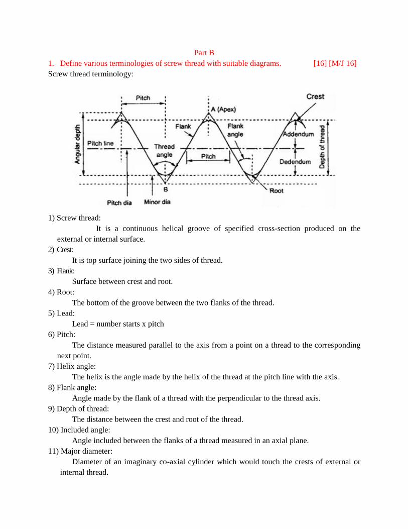
Screw thread terminology:
1) Screw thread:
It is a continuous helical groove of specified cross-section produced on the
external or internal surface.
2) Crest:
It is top surface joining the two sides of thread.
3) Flank:
Surface between crest and root.
4) Root:
The bottom of the groove between the two flanks of the thread.
5) Lead:
Lead = number starts x pitch
6) Pitch:
The distance measured parallel to the axis from a point on a thread to the corresponding
next point.
7) Helix angle:
The helix is the angle made by the helix of the thread at the pitch line with the axis.
8) Flank angle:
Angle made by the flank of a thread with the perpendicular to the thread axis.
9) Depth of thread:
The distance between the crest and root of the thread.
10) Included angle:
Angle included between the flanks of a thread measured in an axial plane.
11) Major diameter:
Diameter of an imaginary co-axial cylinder which would touch the crests of external or
internal thread.
12) Minor diameter (Root diameter or Core diameter):
Diameter of an imaginary co-axial cylinder which would touch the roots of an external
thread.
13) Addendum:
Radial distance between the major and pitch cylinders for external thread.
Radial distance between the minor and pitch cylinder for internal thread.
14) Dedendum:
Radial distance between the pitch and minor cylinder = For external thread.
Radial distance between the major and pitch cylinders = For internal thread.
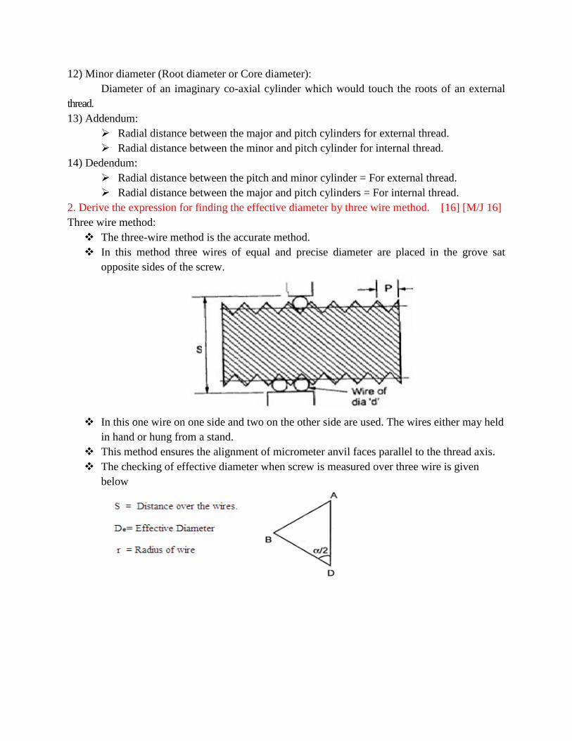
2. Derive the expression for finding the effective diameter by three wire method. [16] [M/J 16]
Three wire method:
The three-wire method is the accurate method.
In this method three wires of equal and precise diameter are placed in the grove sat
opposite sides of the screw.
In this one wire on one side and two on the other side are used. The wires either may held
in hand or hung from a stand.
This method ensures the alignment of micrometer anvil faces parallel to the thread axis.
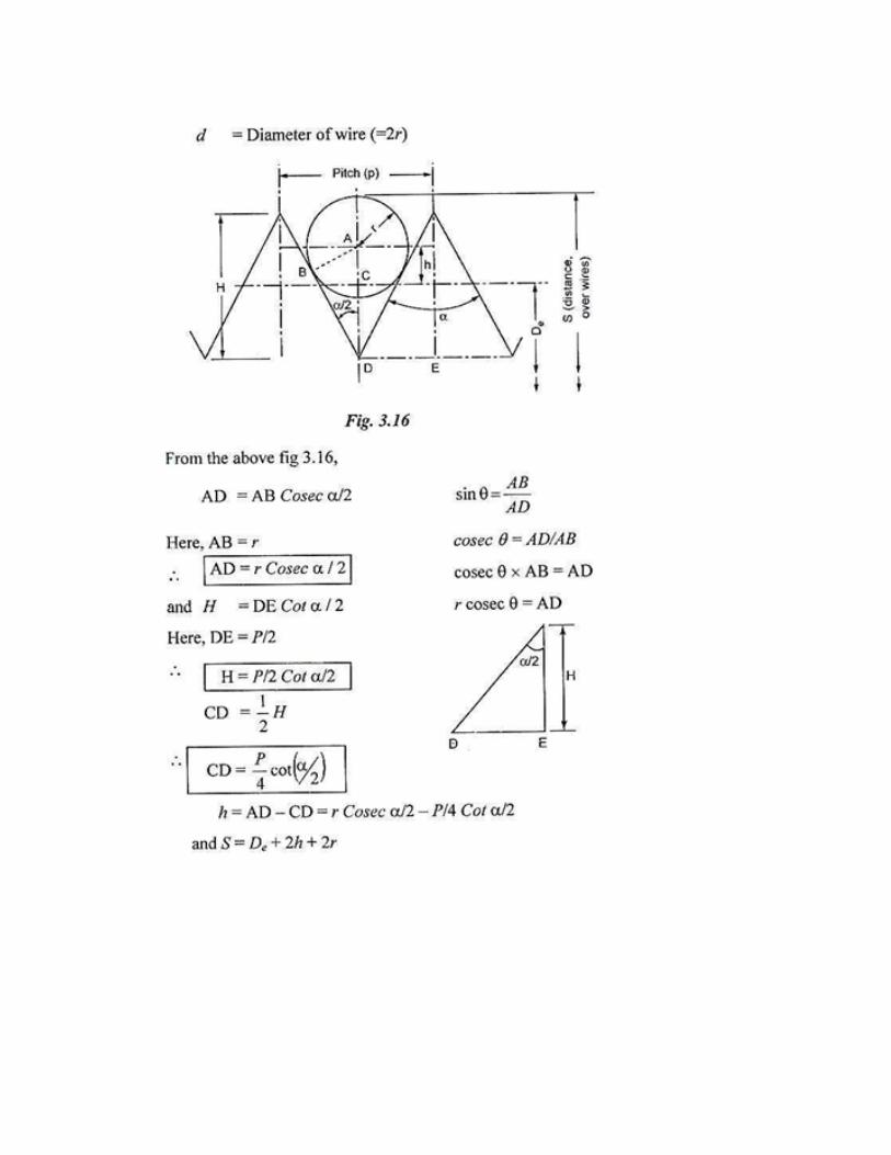
The checking of effective diameter when screw is measured over three wire is given
below
3. Describe the construction of gear tooth Vernier caliper. Explain how it can be used for
measuring the tooth thickness. [16] [N/D 16]
Gear tooth vernier method:
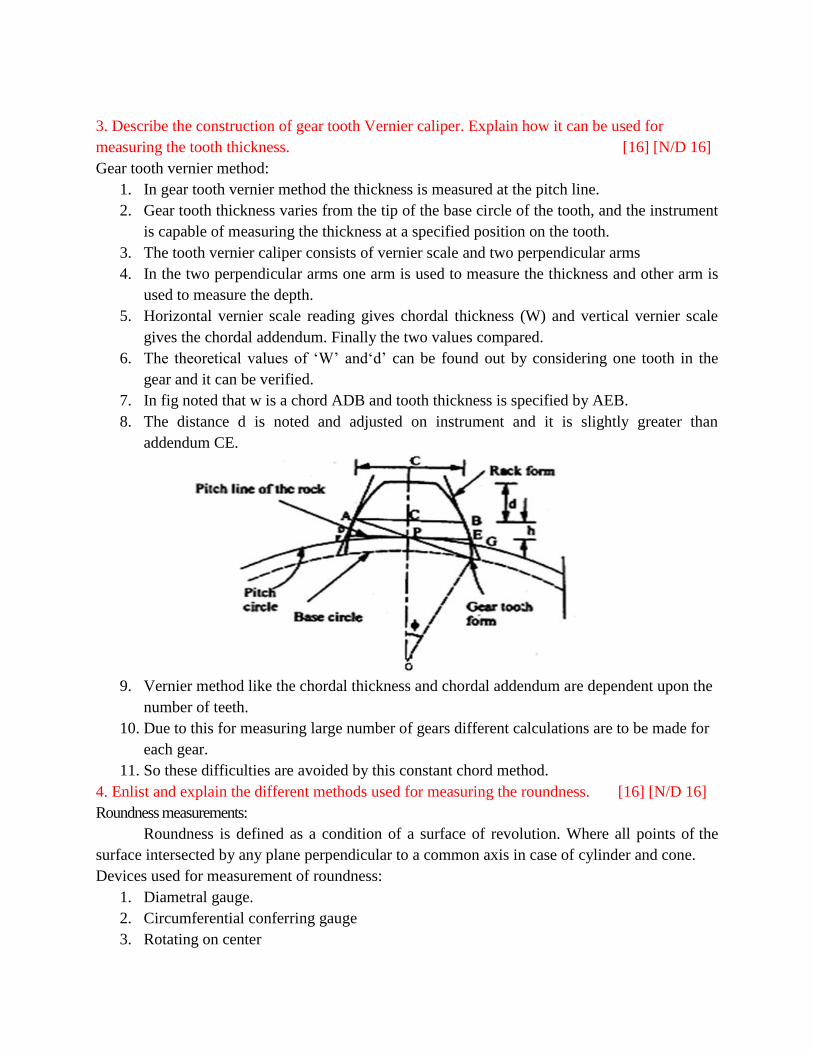
1. In gear tooth vernier method the thickness is measured at the pitch line.
2. Gear tooth thickness varies from the tip of the base circle of the tooth, and the instrument
is capable of measuring the thickness at a specified position on the tooth.
3. The tooth vernier caliper consists of vernier scale and two perpendicular arms
4. In the two perpendicular arms one arm is used to measure the thickness and other arm is
used to measure the depth.
5. Horizontal vernier scale reading gives chordal thickness (W) and vertical vernier scale
gives the chordal addendum. Finally the two values compared.
6. The theoretical values of ‘W’ and‘d’ can be found out by considering one tooth in the
gear and it can be verified.
7. In fig noted that w is a chord ADB and tooth thickness is specified by AEB.
8. The distance d is noted and adjusted on instrument and it is slightly greater than
addendum CE.
9. Vernier method like the chordal thickness and chordal addendum are dependent upon the
number of teeth.
10. Due to this for measuring large number of gears different calculations are to be made for
each gear.
11. So these difficulties are avoided by this constant chord method.
4. Enlist and explain the different methods used for measuring the roundness. [16] [N/D 16]
Roundness measurements:
Roundness is defined as a condition of a surface of revolution. Where all points of the
surface intersected by any plane perpendicular to a common axis in case of cylinder and cone.
Devices used for measurement of roundness:
1. Diametral gauge.
2. Circumferential conferring gauge
3. Rotating on center
4. V-Block
5. Three-point probe.
6. Accurate spindle.
1. Diametral method:
The measuring plungers are located 180° a part and the diameter is measured at several
places.
This method is suitable only when the specimen is elliptical or has an even number of
lobes.
Diametral check does not necessarily disclose effective size or roundness.
This method is unreliable in determining roundness.
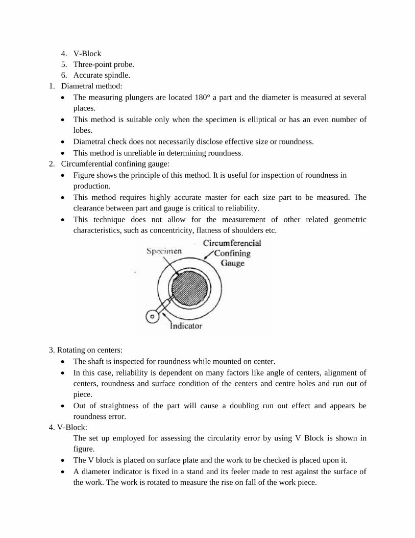
2. Circumferential confining gauge:
Figure shows the principle of this method. It is useful for inspection of roundness in
production.
This method requires highly accurate master for each size part to be measured. The
clearance between part and gauge is critical to reliability.
This technique does not allow for the measurement of other related geometric
characteristics, such as concentricity, flatness of shoulders etc.
3. Rotating on centers:
The shaft is inspected for roundness while mounted on center.
In this case, reliability is dependent on many factors like angle of centers, alignment of
centers, roundness and surface condition of the centers and centre holes and run out of
piece.
Out of straightness of the part will cause a doubling run out effect and appears be
roundness error.
4. V-Block:
The set up employed for assessing the circularity error by using V Block is shown in
figure.
The V block is placed on surface plate and the work to be checked is placed upon it.
A diameter indicator is fixed in a stand and its feeler made to rest against the surface of
the work. The work is rotated to measure the rise on fall of the work piece.
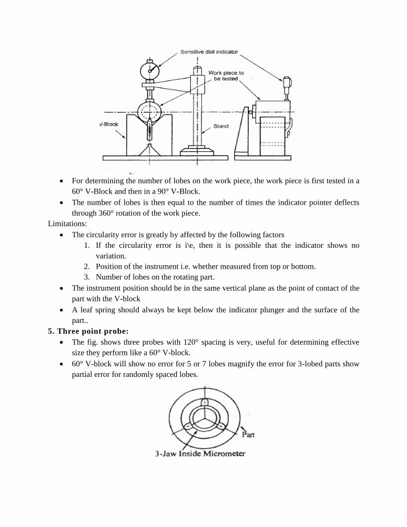
For determining the number of lobes on the work piece, the work piece is first tested in a
60° V-Block and then in a 90° V-Block.
The number of lobes is then equal to the number of times the indicator pointer deflects
through 360° rotation of the work piece.
Limitations:
The circularity error is greatly by affected by the following factors
1. If the circularity error is i\e, then it is possible that the indicator shows no
variation.
2. Position of the instrument i.e. whether measured from top or bottom.
3. Number of lobes on the rotating part.
The instrument position should be in the same vertical plane as the point of contact of the
part with the V-block
A leaf spring should always be kept below the indicator plunger and the surface of the
part..
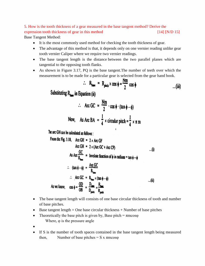
5. Three point probe:
The fig. shows three probes with 120° spacing is very, useful for determining effective
size they perform like a 60° V-block.
60° V-block will show no error for 5 or 7 lobes magnify the error for 3-lobed parts show
partial error for randomly spaced lobes.
5. How is the tooth thickness of a gear measured in the base tangent method? Derive the
expression tooth thickness of gear in this method [14] [N/D 15]
Base Tangent Method:
It is the most commonly used method for checking the tooth thickness of gear.
The advantage of this method is that, it depends only on one vernier reading unlike gear
tooth vernier Caliper where we require two vernier readings.
The base tangent length is the distance between the two parallel planes which are
tangential to the opposing tooth flanks.
As shown in Figure 3.17, PQ is the base tangent.The number of teeth over which the
measurement is to be made for a particular gear is selected from the gear hand book.
The base tangent length will consists of one base circular thickness of tooth and number
of base pitches.
Base tangent length = One base circular thickness + Number of base pitches
Theoretically the base pitch is given by, Base pitch = πmcosφ
Where, φ is the pressure angle
If S is the number of tooth spaces contained in the base tangent length being measured
then, Number of base pitches = S x πmcosφ
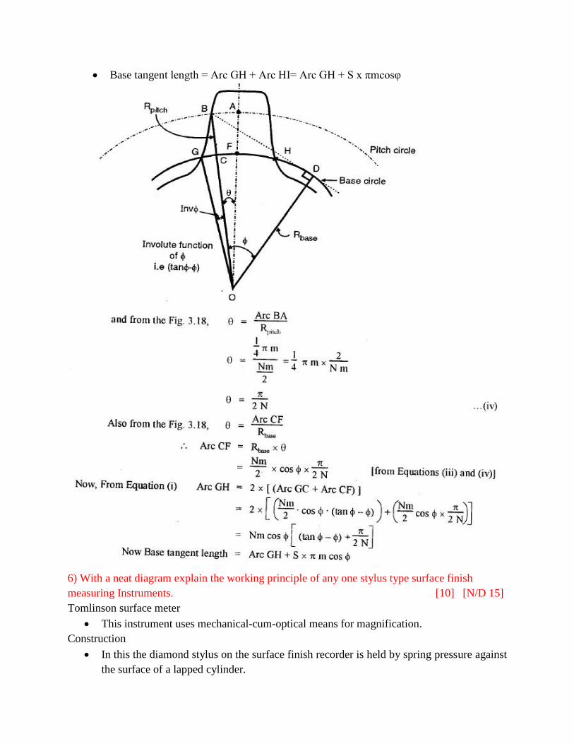
Base tangent length = Arc GH + Arc HI= Arc GH + S x πmcosφ
6) With a neat diagram explain the working principle of any one stylus type surface finish
measuring Instruments. [10] [N/D 15]
Tomlinson surface meter
This instrument uses mechanical-cum-optical means for magnification.
Construction
In this the diamond stylus on the surface finish recorder is held by spring pressure against
the surface of a lapped cylinder.
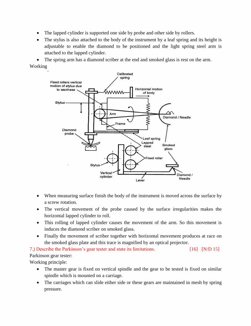
The lapped cylinder is supported one side by probe and other side by rollers.
The stylus is also attached to the body of the instrument by a leaf spring and its height is
adjustable to enable the diamond to be positioned and the light spring steel arm is
attached to the lapped cylinder.
The spring arm has a diamond scriber at the end and smoked glass is rest on the arm.
Working
When measuring surface finish the body of the instrument is moved across the surface by
a screw rotation.
The vertical movement of the probe caused by the surface irregularities makes the
horizontal lapped cylinder to roll.
This rolling of lapped cylinder causes the movement of the arm. So this movement is
induces the diamond scriber on smoked glass.
Finally the movement of scriber together with horizontal movement produces at race on
the smoked glass plate and this trace is magnified by an optical projector.
7.) Describe the Parkinson’s gear tester and state its limitations. [16] [N/D 15]
Parkinson gear tester:
Working principle:
The master gear is fixed on vertical spindle and the gear to be tested is fixed on similar
spindle which is mounted on a carriage.
The carriages which can slide either side or these gears are maintained in mesh by spring
pressure.
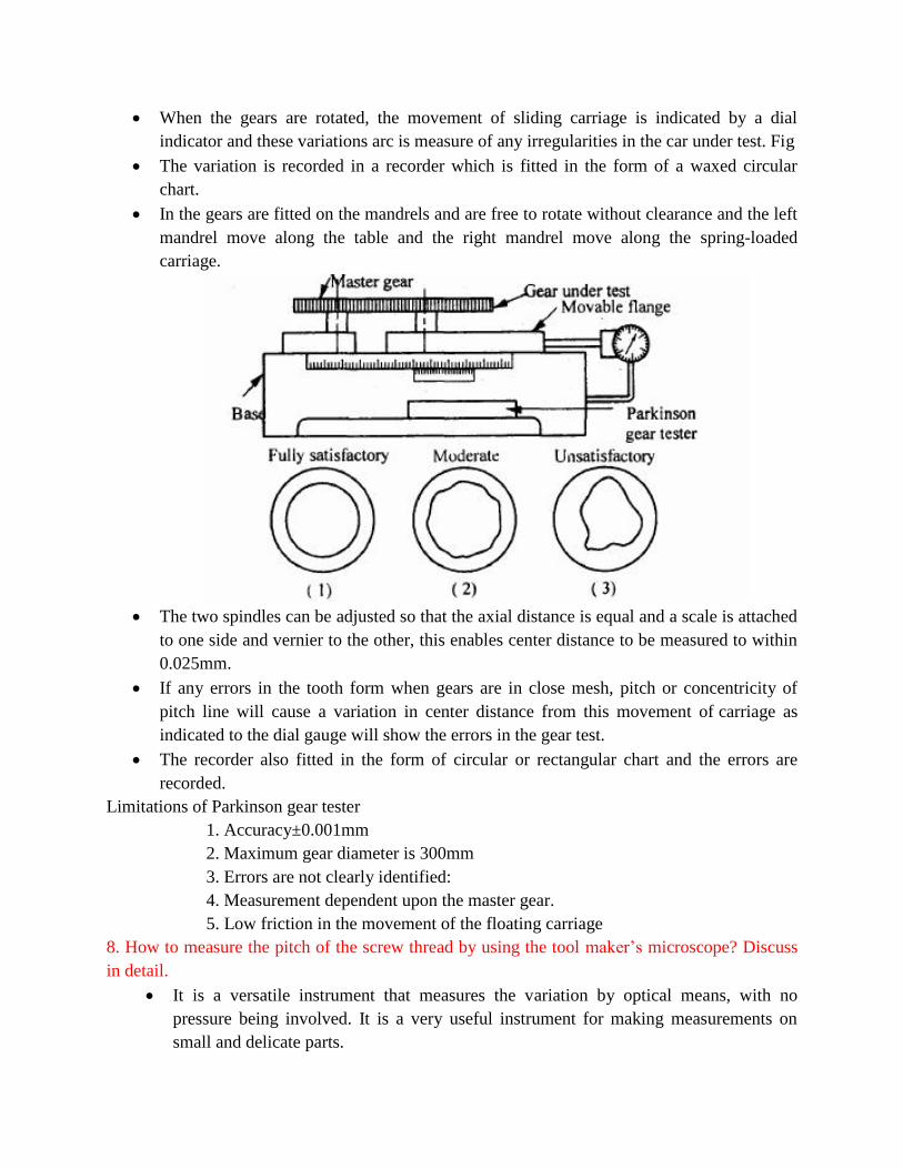
When the gears are rotated, the movement of sliding carriage is indicated by a dial
indicator and these variations arc is measure of any irregularities in the car under test. Fig
The variation is recorded in a recorder which is fitted in the form of a waxed circular
chart.
In the gears are fitted on the mandrels and are free to rotate without clearance and the left
mandrel move along the table and the right mandrel move along the spring-loaded
carriage.
The two spindles can be adjusted so that the axial distance is equal and a scale is attached
to one side and vernier to the other, this enables center distance to be measured to within
0.025mm.
If any errors in the tooth form when gears are in close mesh, pitch or concentricity of
pitch line will cause a variation in center distance from this movement of carriage as
indicated to the dial gauge will show the errors in the gear test.
The recorder also fitted in the form of circular or rectangular chart and the errors are
recorded.
Limitations of Parkinson gear tester
1. Accuracy±0.001mm
2. Maximum gear diameter is 300mm
3. Errors are not clearly identified:
4. Measurement dependent upon the master gear.
5. Low friction in the movement of the floating carriage
8. How to measure the pitch of the screw thread by using the tool maker’s microscope? Discuss
in detail.
It is a versatile instrument that measures the variation by optical means, with no
pressure being involved. It is a very useful instrument for making measurements on
small and delicate parts.
It is designed for following measurements:
1. Measurements of parts of complex form.
2. The profile of external thread as well as tools
3. Measuring center to center distance of holes in any plane
4. Accurate angular measurement
5. Determining the relative position of various points on work.
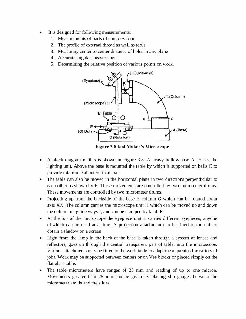
Figure 3.8 tool Maker’s Microscope
A block diagram of this is shown in Figure 3.8. A heavy hollow base A houses the
lighting unit. Above the base is mounted the table by which is supported on balls C to
provide rotation D about vertical axis.
The table can also be moved in the horizontal plane in two directions perpendicular to
each other as shown by E. These movements are controlled by two micrometer drums.
These movements are controlled by two micrometer drums.
Projecting up from the backside of the base is column G which can be rotated about
axis XX. The column carries the microscope unit H which can be moved up and down
the column on guide ways J; and can be clamped by knob K.
At the top of the microscope the eyepiece unit L carries different eyepieces, anyone
of which can be used at a time. A projection attachment can be fitted to the unit to
obtain a shadow on a screen.
Light from the lamp in the back of the base is taken through a system of lenses and
reflectors, goes up through the central transparent part of table, into the microscope.
Various attachments may be fitted to the work table to adapt the apparatus for variety of
jobs. Work may be supported between centers or on Vee blocks or placed simply on the
flat glass table.
The table micrometers have ranges of 25 mm and reading of up to one micron.
Movements greater than 25 mm can be given by placing slip gauges between the
micrometer anvils and the slides.
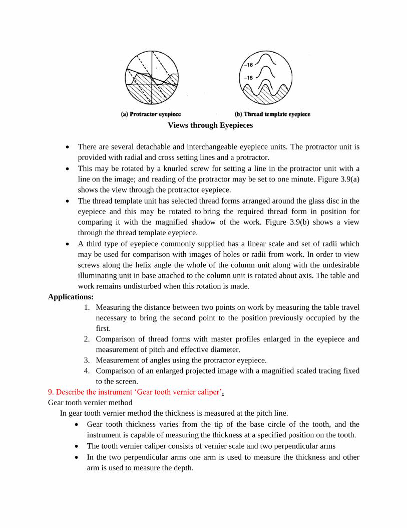
Views through Eyepieces
There are several detachable and interchangeable eyepiece units. The protractor unit is
provided with radial and cross setting lines and a protractor.
This may be rotated by a knurled screw for setting a line in the protractor unit with a
line on the image; and reading of the protractor may be set to one minute. Figure 3.9(a)
shows the view through the protractor eyepiece.
The thread template unit has selected thread forms arranged around the glass disc in the
eyepiece and this may be rotated to bring the required thread form in position for
comparing it with the magnified shadow of the work. Figure 3.9(b) shows a view
through the thread template eyepiece.
A third type of eyepiece commonly supplied has a linear scale and set of radii which
may be used for comparison with images of holes or radii from work. In order to view
screws along the helix angle the whole of the column unit along with the undesirable
illuminating unit in base attached to the column unit is rotated about axis. The table and
work remains undisturbed when this rotation is made.
Applications:
1. Measuring the distance between two points on work by measuring the table travel
necessary to bring the second point to the position previously occupied by the
first.
2. Comparison of thread forms with master profiles enlarged in the eyepiece and
measurement of pitch and effective diameter.
3. Measurement of angles using the protractor eyepiece.
4. Comparison of an enlarged projected image with a magnified scaled tracing fixed
to the screen.
9. Describe the instrument ‘Gear tooth vernier caliper’.
Gear tooth vernier method
In gear tooth vernier method the thickness is measured at the pitch line.
Gear tooth thickness varies from the tip of the base circle of the tooth, and the
instrument is capable of measuring the thickness at a specified position on the tooth.
The tooth vernier caliper consists of vernier scale and two perpendicular arms
In the two perpendicular arms one arm is used to measure the thickness and other
arm is used to measure the depth.
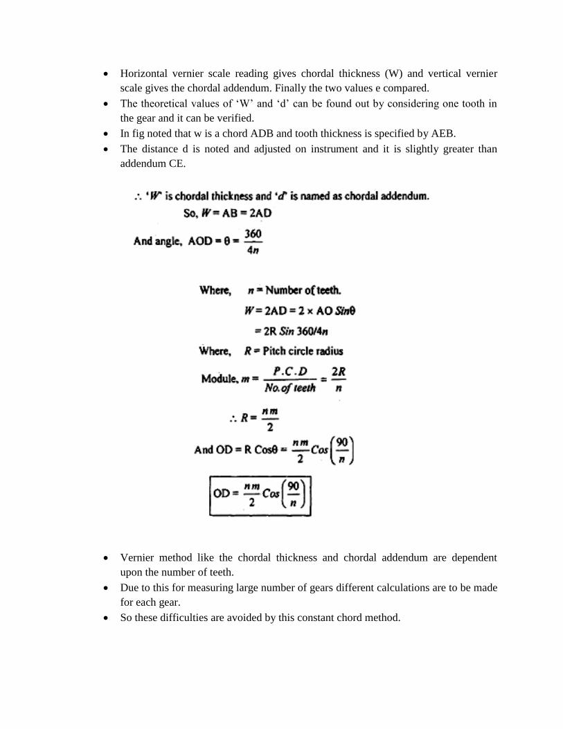
Horizontal vernier scale reading gives chordal thickness (W) and vertical vernier
scale gives the chordal addendum. Finally the two values e compared.
The theoretical values of ‘W’ and ‘d’ can be found out by considering one tooth in
the gear and it can be verified.
In fig noted that w is a chord ADB and tooth thickness is specified by AEB.
The distance d is noted and adjusted on instrument and it is slightly greater than
addendum CE.
Vernier method like the chordal thickness and chordal addendum are dependent
upon the number of teeth.
Due to this for measuring large number of gears different calculations are to be made
for each gear.
So these difficulties are avoided by this constant chord method.
10. Describe the methods used for measuring the radius of a surface.
Radius measurement
In radius measurement we are going see about two methods namely.
1. Radius of circle and
2. Radius of concave surface
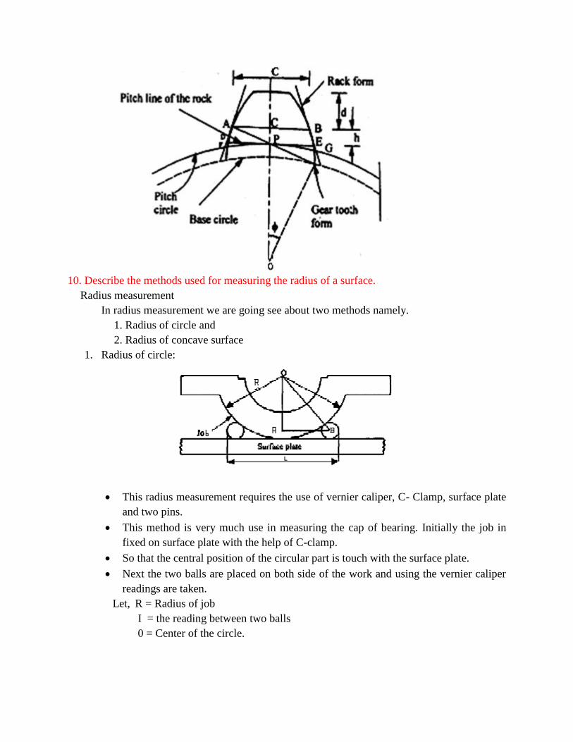
1. Radius of circle:
This radius measurement requires the use of vernier caliper, C- Clamp, surface plate
and two pins.
This method is very much use in measuring the cap of bearing. Initially the job in
fixed on surface plate with the help of C-clamp.
So that the central position of the circular part is touch with the surface plate.
Next the two balls are placed on both side of the work and using the vernier caliper
readings are taken.
Let, R = Radius of job
I = the reading between two balls
0 = Center of the circle.
2. Radius of a concave surface
Here there are two methods used to measure the radius of a concave surface.
a. Edges are well defined.
b. Edges are rounded up.
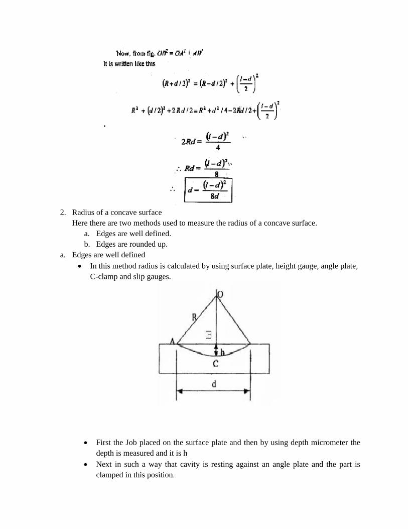
a. Edges are well defined
In this method radius is calculated by using surface plate, height gauge, angle plate,
C-clamp and slip gauges.
First the Job placed on the surface plate and then by using depth micrometer the
depth is measured and it is h
Next in such a way that cavity is resting against an angle plate and the part is
clamped in this position.
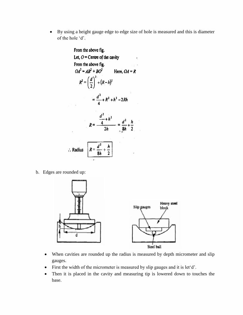
By using a height gauge edge to edge size of hole is measured and this is diameter
of the hole ‘d’.
b. Edges are rounded up:
When cavities are rounded up the radius is measured by depth micrometer and slip
gauges.
First the width of the micrometer is measured by slip gauges and it is let‘d’.
Then it is placed in the cavity and measuring tip is lowered down to touches the
base.
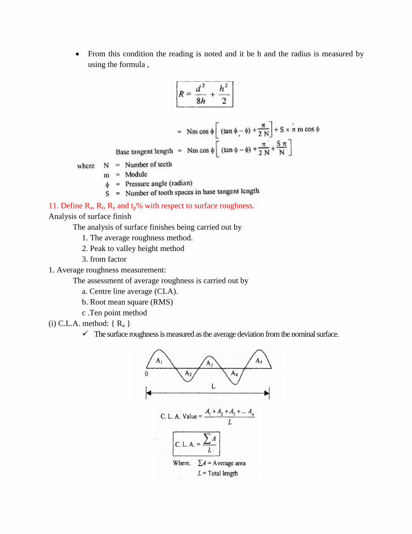
From this condition the reading is noted and it be h and the radius is measured by
using the formula ,
11. Define Ra, Rt, Rz and tp% with respect to surface roughness.
Analysis of surface finish
The analysis of surface finishes being carried out by
1. The average roughness method.
2. Peak to valley height method
3. from factor
1. Average roughness measurement:
The assessment of average roughness is carried out by
a. Centre line average (CLA).
b. Root mean square (RMS)
c .Ten point method
(i) C.L.A. method: { Ra }
The surface roughness is measured as the average deviation from the nominal surface.
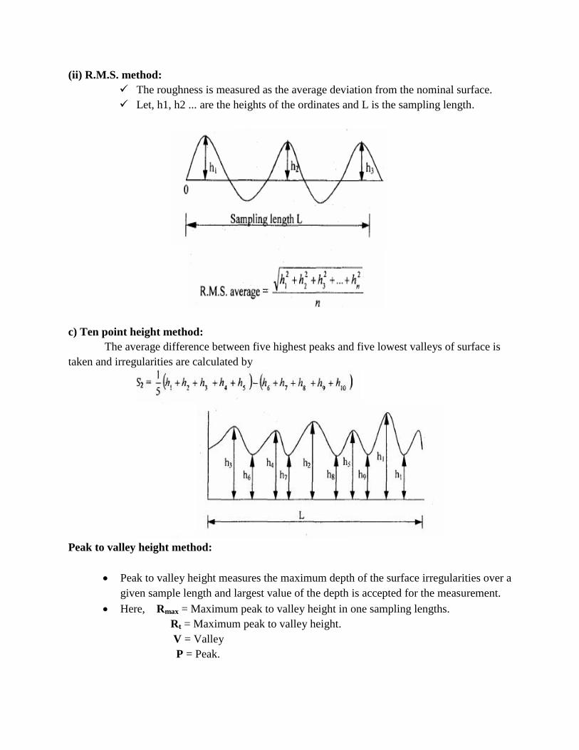
(ii) R.M.S. method:
The roughness is measured as the average deviation from the nominal surface.
Let, h1, h2 ... are the heights of the ordinates and L is the sampling length.
c) Ten point height method:
The average difference between five highest peaks and five lowest valleys of surface is
taken and irregularities are calculated by
Peak to valley height method:
Peak to valley height measures the maximum depth of the surface irregularities over a
given sample length and largest value of the depth is accepted for the measurement.
Here, Rmax = Maximum peak to valley height in one sampling lengths.
Rt = Maximum peak to valley height.
V = Valley
P = Peak.
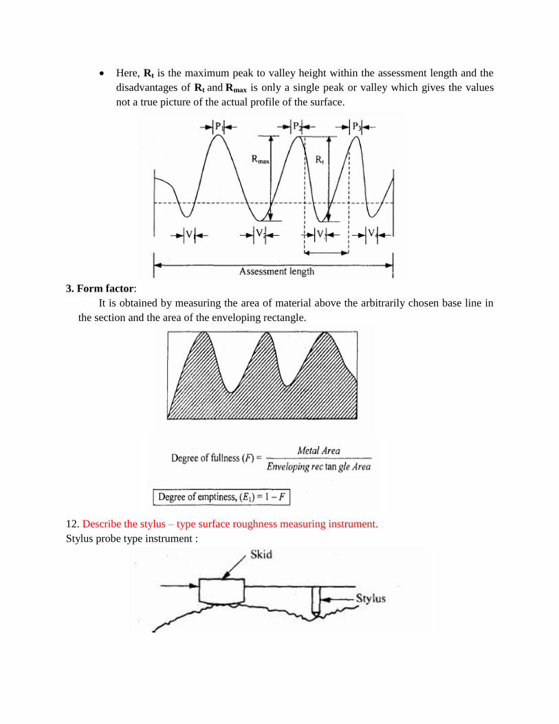
Here, Rt is the maximum peak to valley height within the assessment length and the
disadvantages of Rt and Rmax is only a single peak or valley which gives the values
not a true picture of the actual profile of the surface.
3. Form factor:
It is obtained by measuring the area of material above the arbitrarily chosen base line in
the section and the area of the enveloping rectangle.
12. Describe the stylus – type surface roughness measuring instrument.
Stylus probe type instrument :
Principle
When the stylus be moved over the surface which is to be measured, the irregularities in
the surface texture is measured and it is used to assess the surface finish of the work
piece.
Working
The stylus type instruments consist of skid, stylus, amplifying device and recording
device.
The skid is slowly moved over the surface by hand or by motor drive. The skid follows
the irregularities of the surface and the stylus moves along with skid.
When the stylus moves vertically up and down and the stylus movements’ are magnified,
amplified and recorded to produce a trace.
Then it is analyzed by automatic device.
Advantage
Any desired roughness parameter can be recorded.
Disadvantages
Fragile material cannot be measured.
High Initial cost.
Skilled operators are needed to operate.
13. Define straightness, describe any one method of measuring straightness of a surface.
Straightness measurement
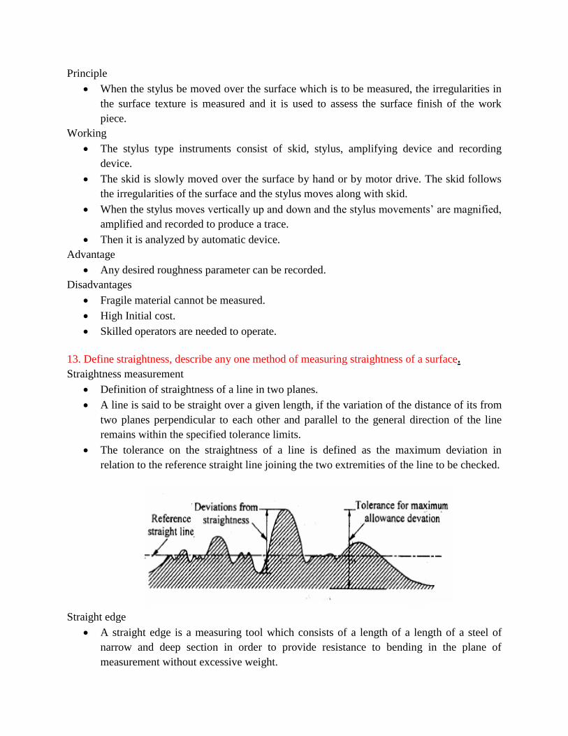
Definition of straightness of a line in two planes.
A line is said to be straight over a given length, if the variation of the distance of its from
two planes perpendicular to each other and parallel to the general direction of the line
remains within the specified tolerance limits.
The tolerance on the straightness of a line is defined as the maximum deviation in
relation to the reference straight line joining the two extremities of the line to be checked.
Straight edge
A straight edge is a measuring tool which consists of a length of a length of a steel of
narrow and deep section in order to provide resistance to bending in the plane of
measurement without excessive weight.
For checking the straightness of any surface, the straight edge is placed over the surface
and two are viewed against the light, which clearly indicate the straightness..
The gap between the straight edge and surface will be negligibly small for perfect
surfaces. Straightness is measured by observing the color of light by diffraction while
passing through the small gap.
If the color of light be red, it indicates a gap of 0.0012 to 0.0075mm.
A more accurate method of finding the straightness by straight edges is to place tin equal
slip gauges at the correct point for minimum deflection and to measure the uniformity of
space under the straight edge with slip gauges.
Test for straightness by using spirit level and Autocollimator:
Sprit Level / Auto Collimator Method:
The sprit level or autocollimator use reference lines which are straight.
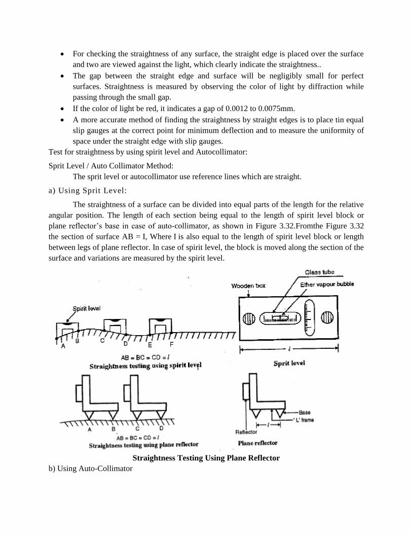
a) Using Sprit Level:
The straightness of a surface can be divided into equal parts of the length for the relative
angular position. The length of each section being equal to the length of spirit level block or
plane reflector’s base in case of auto-collimator, as shown in Figure 3.32.Fromthe Figure 3.32
the section of surface AB = I, Where I is also equal to the length of spirit level block or length
between legs of plane reflector. In case of spirit level, the block is moved along the section of the
surface and variations are measured by the spirit level.
Straightness Testing Using Plane Reflector
b) Using Auto-Collimator
This is an optical instrument, which is used for measuring the small angular deviation. It
gives accurate result for the small angular differences.
Principle of working of auto collimator
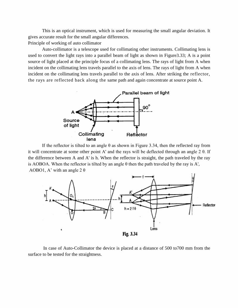
Auto-collimator is a telescope used for collimating other instruments. Collimating lens is
used to convert the light rays into a parallel beam of light as shown in Figure3.33; A is a point
source of light placed at the principle focus of a collimating lens. The rays of light from A when
incident on the collimating lens travels parallel to the axis of lens. The rays of light from A when
incident on the collimating lens travels parallel to the axis of lens. After striking the reflector,
the rays are reflected back along the same path and again concentrate at source point A.
If the reflector is tilted to an angle θ as shown in Figure 3.34, then the reflected ray from
it will concentrate at some other point A' and the rays will be deflected through an angle 2 θ. If
the difference between A and A' is h. When the reflector is straight, the path traveled by the ray
is AOBOA. When the reflector is tilted by an angle θ then the path traveled by the ray is A',
AOBO1, A’ with an angle 2 θ
In case of Auto-Collimator the device is placed at a distance of 500 to700 mm from the
surface to be tested for the straightness.
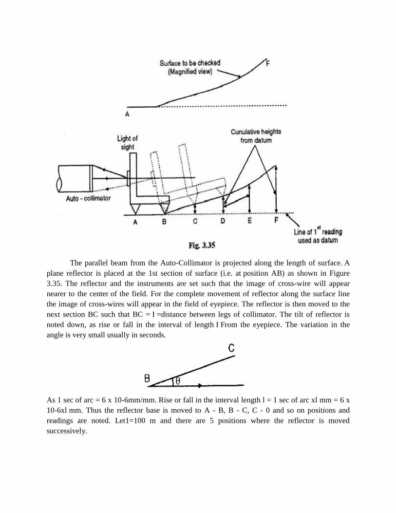
The parallel beam from the Auto-Collimator is projected along the length of surface. A
plane reflector is placed at the 1st section of surface (i.e. at position AB) as shown in Figure
3.35. The reflector and the instruments are set such that the image of cross-wire will appear
nearer to the center of the field. For the complete movement of reflector along the surface line
the image of cross-wires will appear in the field of eyepiece. The reflector is then moved to the
next section BC such that BC = I =distance between legs of collimator. The tilt of reflector is
noted down, as rise or fall in the interval of length I From the eyepiece. The variation in the
angle is very small usually in seconds.
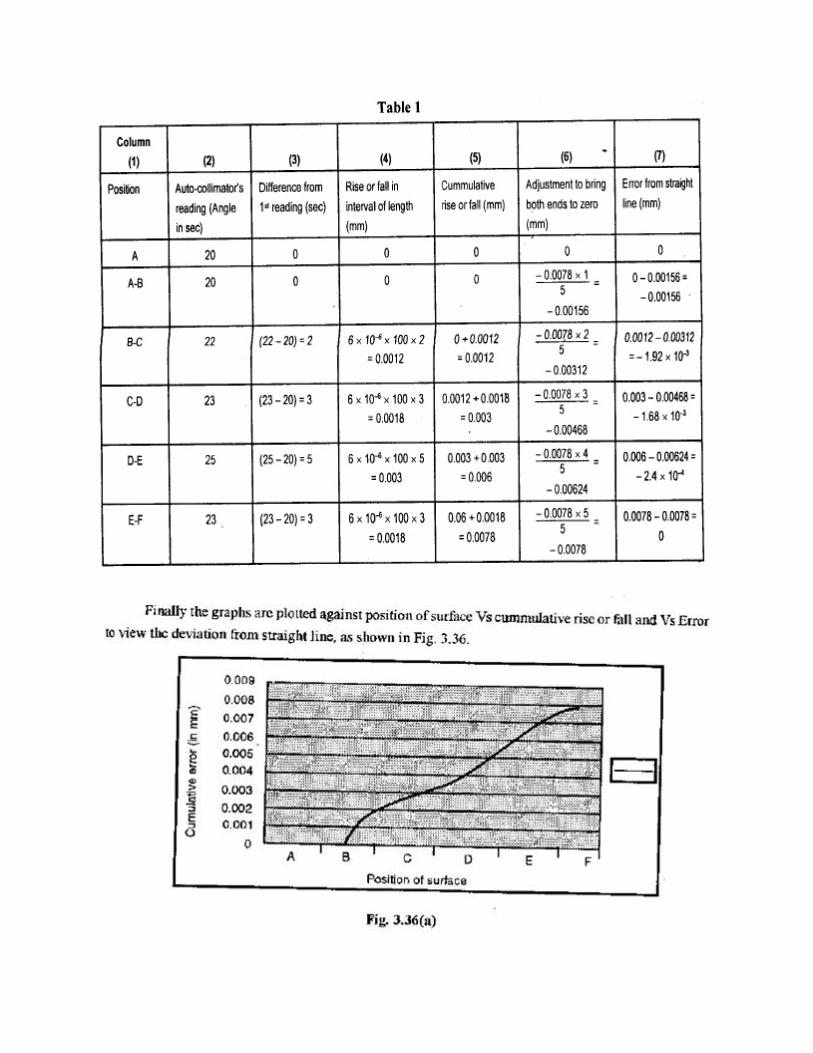
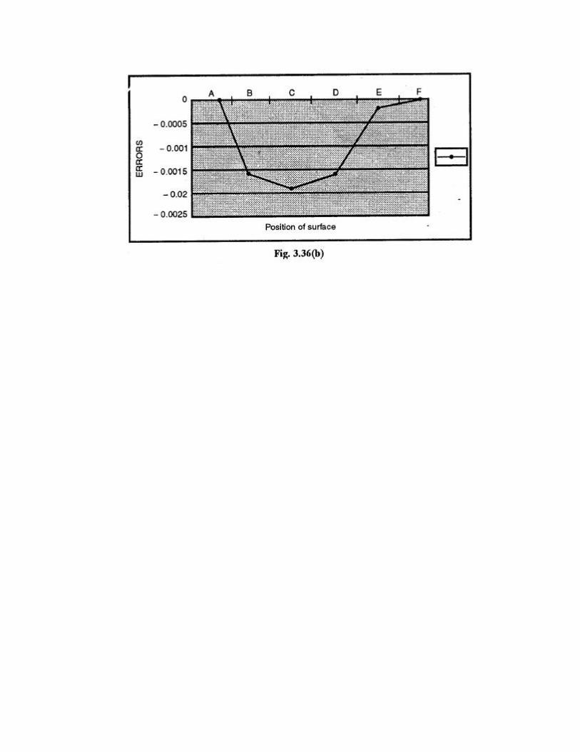
As 1 sec of arc = 6 x 10⁻⁶mm/mm. Rise or fall in the interval length l = 1 sec of arc xl mm = 6 x
10-6xl mm. Thus the reflector base is moved to A - B, B - C, C - 0 and so on positions and
readings are noted. Let1=100 m and there are 5 positions where the reflector is moved
successively.
14. Briefly explain the step by step procedure for determining the flatness of a surface with neat
sketch.
Flatness Testing
Flatness testing is possible by comparing the surface with an accurate surface. This
method is suitable for small plates and not for large surfaces. Mathematically
flatness error of a surface states that the departure from flatness is the minimum.
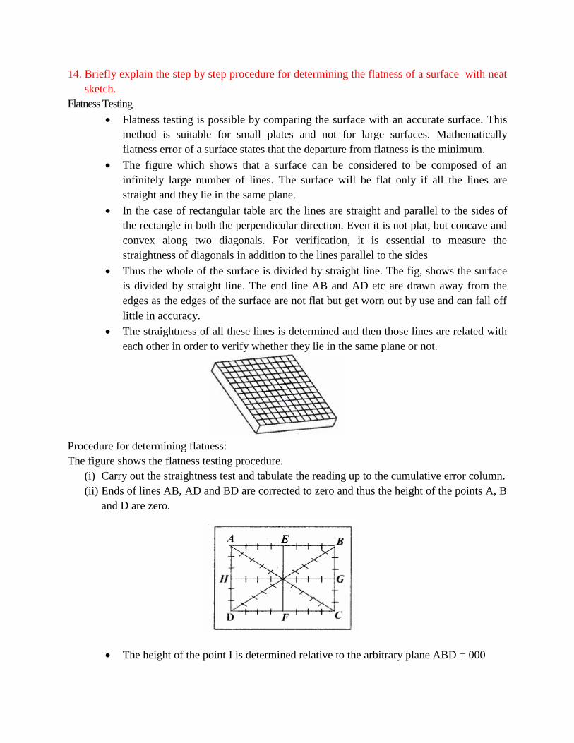
The figure which shows that a surface can be considered to be composed of an
infinitely large number of lines. The surface will be flat only if all the lines are
straight and they lie in the same plane.
In the case of rectangular table arc the lines are straight and parallel to the sides of
the rectangle in both the perpendicular direction. Even it is not plat, but concave and
convex along two diagonals. For verification, it is essential to measure the
straightness of diagonals in addition to the lines parallel to the sides
Thus the whole of the surface is divided by straight line. The fig, shows the surface
is divided by straight line. The end line AB and AD etc are drawn away from the
edges as the edges of the surface are not flat but get worn out by use and can fall off
little in accuracy.
The straightness of all these lines is determined and then those lines are related with
each other in order to verify whether they lie in the same plane or not.
Procedure for determining flatness:
The figure shows the flatness testing procedure.
(i) Carry out the straightness test and tabulate the reading up to the cumulative error column.
(ii) Ends of lines AB, AD and BD are corrected to zero and thus the height of the points A, B
and D are zero.
The height of the point I is determined relative to the arbitrary plane ABD = 000
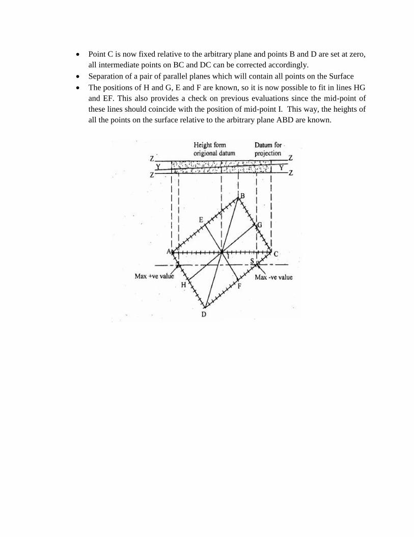
Point C is now fixed relative to the arbitrary plane and points B and D are set at zero,
all intermediate points on BC and DC can be corrected accordingly.
Separation of a pair of parallel planes which will contain all points on the Surface
The positions of H and G, E and F are known, so it is now possible to fit in lines HG
and EF. This also provides a check on previous evaluations since the mid-point of
these lines should coincide with the position of mid-point I. This way, the heights of
all the points on the surface relative to the arbitrary plane ABD are known.