me2037 maintenance engineering syllabus …fmcet.in/mech/me2037_uw.pdf · me2037 maintenance...
TRANSCRIPT

ME2037 MAINTENANCE ENGINEERING SYLLABUS ME2037 MAINTENANCE ENGINEERING L T P C
(COMMON TO MECHANICAL AND PRODUCTION) 3 0 0 3
OBJECTIVES: • To enable the student to understand the principles, functions and practices adapted in industry
for the successful management of maintenance activities.
• To explain the different maintenance categories like Preventive maintenance, condition
monitoring and repair of machine elements.
• To illustrate some of the simple instruments used for condition monitoring in industry.
UNIT I PRINCIPLES AND PRACTICES OF MAINTENANCE PLANNING 9
Basic Principles of maintenance planning – Objectives and principles of planned maintenance
activity – Importance and benefits of sound Maintenance systems – Reliability and machine
availability – MTBF, MTTR and MWT – Factors of availability – Maintenance organization –
Maintenance economics.
UNIT II MAINTENANCE POLICIES – PREVENTIVE MAINTENANCE 9
Maintenance categories – Comparative merits of each category – Preventive maintenance,
maintenance schedules, repair cycle - Principles and methods of lubrication – TPM.
UNIT III CONDITION MONITORING 9
Condition Monitoring – Cost comparison with and without CM – On-load testing and off-load
testing – Methods and instruments for CM – Temperature sensitive tapes – Pistol thermometers –
wear-debris analysis
UNIT IV REPAIR METHODS FOR BASIC MACHINE ELEMENTS 10
Repair methods for beds, slideways, spindles, gears, lead screws and bearings – Failure analysis
– Failures and their development – Logical fault location methods – Sequential fault location.
UNIT V REPAIR METHODS FOR MATERIAL HANDLING EQUIPMENT 8
Repair methods for Material handling equipment - Equipment records –Job order systems -Use
of computers in maintenance.
TOTAL: 45 PERIODS
TEXT BOOKS: 1. Srivastava S.K., “Industrial Maintenance Management”, - S. Chand and Co., 1981
2. Bhattacharya S.N., “Installation, Servicing and Maintenance”, S. Chand and Co., 1995
REFERENCES: 1. White E.N., “Maintenance Planning”, I Documentation, Gower Press, 1979.
2. Garg M.R., “Industrial Maintenance”, S. Chand & Co., 1986.
3. Higgins L.R., “Maintenance Engineering Hand book”, McGraw Hill, 5th Edition, 1988.
4. Armstrong, “Condition Monitoring”, BSIRSA, 1988.
5. Davies, “Handbook of Condition Monitoring”, Chapman &Hall, 1996.
6. “Advances in Plant Engineering and Management”, Seminar Proceedings - IIPE, 1996.

UNIT I
L1 PRINCIPLES & PRCTICES OF MAINTENANCE PLANNING
Maintenance:
It is the routine and recurring process of keeping a particular machine or
asset in its normal condition o that it can deliver the excepted performance or
service without any loss or damage.
Principles of Maintenance Planning
Maintenance principles are followed in a system to guide the staff to work
efficiently and effectively to achieve the overall objectives of the maintenance
system.
i) Plant Management in Maintenance work:
The main role of the maintenance function is to provide safe and effective
operation of the equipment to achieve the designed targets on time with
economic usage of resources.
ii) Production and Maintenance Objectives:
The plant is driven by the production targets. The objective of these
maintenance function is to support these targets.
Information based Decision Making:
The maintenance objectives are successfully achieved by the use of
reliable information system.
1

2

Planning of Maintenance Function :
All the maintenance functions are to be carefully executed by a way
of
proper planning to ensure the effective utilization of manpower and materials.
Manpower for Maintenance:
The manpower requirements of the maintenance system must be carefully
evaluated based on the time and motion study.
Workforce control:
Determination of exact workforce required to meet the maintenance
objectives of the system is difficult task due to the element of uncertainty. Hence
the proper control and monitoring of workforce are needs to be ensured .
Role of spar parts:
A good maintenance management system requires appropriate
tools. So the system should have good quality tools and that too available in
required quantities to ensure the proper function of the maintenance works.
3

Important Factor to be considered in Maintenance Planning
The maintenance work include the following factors
⦁ Job Distribution
⦁ Programme
⦁ Man Power Allocation
⦁ Staffing
⦁ Planning Techniques
⦁ Planning Procedure.
⦁ Maintenance Control
Jot Distribution :
The first and foremost task in maintenance planning is the distribution of
the pots to the personnel for preventive and emergence maintenance works.
Programme:
A maintenance programme is a well formulated combination of the
available skills and resources that ensures optimum and appropriate utilization to
meet the objective of the organization.
Man Power Allocation:
It is the most important task of the maintenance management group. The
central idea of man power allocation can be drafted using the information
available from maintenance records and planning the tasks to meet the
objectives of the organization.
Staffing:
It is the task of provided the required manpower for the maintenance
4

function. The advantage of preventine maintenance is that the work can be
planned and scheduled properly for the effective use of resources.
Planning Techniques:
The planning methods are Gantt charts, Critical path method are recently
used for maintenance planning and scheduling.
Maintenance Control:
It is the auditing technique to ensure the effective utilization of the
maintenance budget. This involves the integration of with the
system.
2 marks
5

L2
Important and benefits of sound maintenance management system
The profit of any industry depends only on the return of the investment.
The capital cost and operating cost are the major factors involved in any
industrial investment. The life of the equipment and maintenance schedule
information provided by manufacturer may not be realized in practice to make
the need for having a sound management system.
The following are the benefits of sound maintenance management
system.
⦁ Minimization of colourtime.
⦁ Improvement in availability of system.
⦁ Extended life of equipment.
⦁ Safety and smooth operation of the process
⦁ Provide adequate back up supply
⦁ Minimization of normal expected wear and tear of equipment.
⦁ Safety of the personal involved in the organization.
⦁ Increased reliability of the system.
⦁ Provide proper working environment.
6

RELIABILITY IN MAINTENANCE
The concept of reliability has found increased use in industries
engineering maintenance and management.
Need for reliability of Maintenance :
The reliability of a system, equipment and product is very important
aspect of quality for its consistent performance over the expected life span.
Reality is defined as the probability that ac component / system, when
operating under given condition will perform it intended functions adequate for a
specified period of time. It refers to the like hood that equipment will not fail
during its operation. The four important factors required in the determination of
reliability are
⦁ Reliability expressed as probability
⦁ Adequate performance acquirements
⦁ Duration of adequate performance.
⦁ Environmental or operating conditions.
i) Realiability expressed as probability
it is the ratio of the number of times we can expect an event to occur to
the total number of trail undertaken. A Reliability factor can be expressed as
probability. A reliability factor equal to one means that device performs
satisfactorily for the prescribed duration under the give environmental condition.
ii) Adequate Performance Requiement:
a system may perform satisfactorily even though one or more components
7

may not be functioning. In reliability analysis there is a need to define the
magnitude of satisfactory or adequate performance of the system.
iii) Duration of Adequate Performance:
The duration of adequate performance is used to state the time up to
which the desired performance of the system is achieved under the given
operating conditions.
iv) Environmental or Operating condition:
environmental condition indicate the prevailing conditions at which the
system is under operation.
Failure pattern of equipment
The failure pattern of equipment over its whole life cycle can be
represented in the diagram given below. In phase I, the failure pattern inherent in
a new product because of manufacturing or design defects. Phase II shows the
useful life period of an equipment when the failure rates are normally modulate
at the equipment gets set to the working environment. In Phase III, the failures
are excusing due to wear out failure that are caned due to again of the
equipment.
8
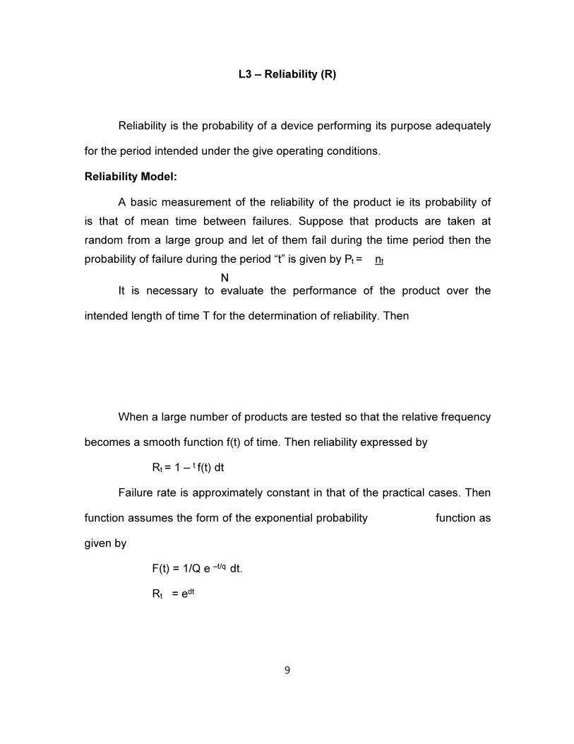
L3 – Reliability (R)
Reliability is the probability of a device performing its purpose adequately
for the period intended under the give operating conditions.
Reliability Model:
A basic measurement of the reliability of the product ie its probability of
is that of mean time between failures. Suppose that products are taken at
random from a large group and let of them fail during the time period then the
probability of failure during the period “t” is given by Pt = nt
NIt is necessary to evaluate the performance of the product over the
intended length of time T for the determination of reliability. Then
When a large number of products are tested so that the relative frequency
becomes a smooth function f(t) of time. Then reliability expressed by
Rt = 1 – t f(t) dt
Failure rate is approximately constant in that of the practical cases. Then
function assumes the form of the exponential probability function as
given by
F(t) = 1/Q e –t/q dt.
Rt = edt
9

Probability of Failure
The probability of failure is the ratio of the number of unite that failed at
specified period of time to the total population.
Mean Failure Rate (h)
The mean failure is the rate h is obtained by finding the mean of the
failure rates for specified period of time.
Mean time is failure (MTTF)
Let t, is the time to failure for the first specimen, t is the time to failure for
the second specimen and tn is the time to failure for the N specimen. Hence the
mean time to failure for N specimens are
HTTF = (t1+t2+…….tn) /n
= 1/N
It is difficult to record the failure for each component when the numbers of
specimens tested are large. Instead, we can record the number which fails
during the specific intervals of time.
Mean time between failures (HTBF)
Mean time between failures (HTBF) is the mean or average time between
successive failures of a product. Mean time between failures refers to the
average time of breakdown until the device is beyond repair.
Mean time to Repair (MTTR)
Mean time to repair (MTTR) is the arithmetic mean of the time required to
perform maintenance action. MTTR is defined as the ratio of total maintenance
time and number of maintenance action.
10

MTTR = Total maintenance time
Number of maintenance action
Maintenance Action Rate:
Maintenance action rate is the number of maintenance action that can be
cassied out on equipment per hour.
= 1/MTTR
Types of Reliability:
Reliability can be generally of two types
Inherent Reliability
It is associated with the quality of the material and design of
machine parts
Achievable Reliability
It depends upon other factor such as maintenance and operation of
the equipment.
L4- MAINTAINABILITY
It is a concept closely related to the characteristics of equipments design
and installation. It is defined as the probability that a unit or system will be
restored to specified working conditions within a given period when maintenance
action is taken in accordance with the prescribed procedures and resources.
Availability
It is the ratio of the time at which the equipment is available for the
designated operation service to the total time of operation and maintenance of
11

the equipment. It is also defined as the ration of equipments uptime to the
equipment uptime and down time over a specified period of time.
The three types of availability are
⦁ Inherent availability
⦁ Achieved availability
⦁ Operational availability
Inherent availability
It is the probability that a system or equipment shall operate satisfactorily
when used under prescribed conditions in a ideal support environment without
any scheduled or preventive maintenance at any given time.
Inherent availability = MTBM/ MTBM+MTTR
Achieved availability
It is the probability that a system or equipment shall operate satisfacily
when used under prescribed conditions in an ideal support environment with
periodic preventive and corrective maintenance at any given time.
Achieved availability = MTBM/ MTBM+M
Operational Availability
In industrial system a certain amount of delay will always caused by time
element such as supply downtime and administrative downtime.
Operational availability = MTBM/ MTBM+MDT
Where MOT is the mean downtime is the satisfied mena of the downtimes
including the supply downtime and administrative downtime.
Resources
Resources include men, sparks and tools involved in the task of
maintenance.
Administration
It include a nearby of authority and responsibility for decision making and
plans for the execution of work.
12

Workplanning and control system
This is the mechanism for planning and scheduling the wok. This also
include the feedback of information to drive the maintenance effort to its defined
objective.
The basic objective of the maintenance organization is the ensure that the
maintenance function ae carried out effectively and hence to minimize the
production loss due to maintenance. There has to be a close relationship
between the production and maintenance departments to achieve the desired
targets of the industry. Continuous monitoring of planned preventive
maintenance schedules identififed for the identified for the equipment is required
to complete the maintenance tasks in time.
A maintenance organization can be countered as made up of three basic
and necessary components.
Resources
Administration
Work planning and control system.
Maintenance of modern equipment and industry requires a healthy,
balanced and rationalized organization, devoted to achieve the goals of
maintenance task. The organization required for any system can be formed after
study of the existing continuous and also the future demands of the industry.
The increasing complexity of present day equipment maintenance
management has brought into focus two other aspects known as maintainability
and availability, both of them are closely related to reliability.
2 marks
13

L 5 – TASKS OF MAINTENANCE ORGANISATION
The tasks of the maintenance are as follows:
⦁ Identification of organization roles pertaining maintenance function.
⦁ Determination of maintenance workload.
⦁ Uniform distribution of total maintenance work to all the personal in
the department.
⦁ Identification and assignment of essential works to the various
sections of the maintenance department
⦁ Proper knowledge about the technical experlise/ experience of the
workers deputed for the particular part
⦁ Proper training of the staff of maintenance to meet the growing
demands of the industry and to catch up with the modern trends in
maintenance.
⦁ Designing the polices and procedures at an early stage to help the
maintenance departe4mnet to achieve the goals of the industry.
Maintenance Functions and Activities
The functions and activities of the maintenance organization are as
follows:
⦁ Identifying areas for implementation of preventive maintenance
program.
⦁ Making suitable arrangements for maintenance facilities for carrying
out the maintenance works properly.
⦁ Planning an scheduling the total maintenance work
14

⦁ Ensuring proper and timely supply of spare parts.
⦁ Managing proper inventory control of materials spares and tools
required for maintenance.
⦁ Standardization of maintenance work.
⦁ Implementing modifications to the existing equipment wherever
possible.
⦁ Assisting the purchase department in processing materials.
⦁ Identification of obsdate and surplus equipment for replacement and
disposals.
⦁ Training of maintenance personnel.
⦁ Analysis of future demands and forecast the role of maintenance
activities.
⦁ Implementation of safety norms and procedures
⦁ Ensuring safety of personnel and equipment.
Types of maintenance organization
The selections of a type of maintenance system will largely depend on the
structure of an industry. Maintenance organization can be broadly classified into
three types as follows.
i) Decentralized
this is suitable for large sized plants where enter unit communication is
difficult to get. In this type of organization the maintenance is difficult to get. In
this type of organization, the maintenance is under the control of chief engineer
of production to ensure understanding between the production and maintenance
department.
15

ii) Controlized
this is suitable for small units where unit communication is feasible. In this
typeof organization the maintenance is under the control of chief maintenance
engineer. The responsibilities accountability is with the concerned department
heads.
iii) Partially Controlized
this is the modified version of controlized maintenance organization and
suitable for the industry where the units are located at far away locations.
In this type of organization, the maintenance personal attached with
production unit will carryout the routine maintenance works. Scheduled
maintenance works such as overhauls. Planned maintenance work, procurement
of spare parts are under the control of chief maintenance engineer at the control
office.
There are basically tow atleast two types of organization are followed in
most of the industries. They are
⦁ Line organization
⦁ Line staff organization.
16

L6 – Line Organization
Line organization consists of a general foreman and a number of
specialist foremen with their under them is shown below.
General Foreman
Foreman Electrical Storekeeper
The specialist foreman execute maintenance work in their respective
areas while the general foreman supervises the total work under his control and
the various maintenance tasks carried out in the industry. This kind of structure is
an old type maintenance organization.
LINE STAFF ORGNISATION
A few more staff members such as storekeeper and clerk are added to
the line organization to form the line organization structure as given below.
The advantage lies in separating the maintenance work from the
storekeeping and the role of clerk is to record the maintenance activities. The
recording of maintenance related activities helps the organization to restructure
the strategies adopted to achieve the objectives of maintenance.
LINE STAFF ORGANISATION
Maintenance functional organization
Maintenance functional organization is the structure based on craft
concept. In this organization structure persons joined the organization as
appentices and devoted to higher positions such as forman after sufficient
experience in their respective jobs. This organization the maintenance functional
organization in which few workers are placed under each functional foreman.
Controlly Controlled Maintenance Organization
The limitation of this kind of maintenance is that it is possible onl for
equipments which can be shifted to workshop.
Area Maintenance organization
17

Area maintenance organization provides better utility of manpower when
the units are located at various locations.
For example mining industry, area maintenance manage takes care of
maintenance for a particular area and is equipped with number of workers to
carryout maintenance works including emergency work.
18

L7 – GENERAL ORGANIGATION OF MAINTANANCE DAPARTMENT
Externalmaintanance service
It is available in two forms contract maintenance service and
manufacturers after sale service
Advantages of external maintenance service
⦁ It is very economical
⦁ Technically better and specialist are responsible for maintenance activities
⦁ Skill preservation
⦁ Better service
⦁ Updating to modern and existing trends and needs
Outsourcing in maintenance
The term outsourcing assumed recent importance in the area of computer
information technology and communication due to emergence of business
process outsourcing (BPO) outsourcing is followed in small industries to hand
once the maintenance activities to external agencies. This is due to the reason
that economy of the industry does not permit to have maintenance people on
their own. It is followed in large industries also ensure maximum control over the
maintenance activities.
⦁ Lost of maintenance is minimized
⦁ No need for having maintenance as a department.
⦁ Better quality of service achieved through employing specialists.
⦁ Better maintenance practice
⦁ Performance metrics are clearly defined and achieved by ooutsourcing
the maintenance jobs
19

Maintenance Economics
Lift cost Analysis:
The factors to be considered in the purchase of equipment for industries
include the cost, quality, performance and maintenance requirements. Some
balance is to be made between the capital cost andn operating cost of the
equipment in finding the suitability of the equipment.
Life cycle costing is the cost analysis for the equipment in an industry that
accounts total cost of the equipment over a span of time which includes the
capital cost, operating cost and maintenance cost. The aim of life cycle losting is
to acertain the total cost of equipment over the span of its entire life period.
Advantages of life cycle costing
Integration of engineering, economics and financial aspects lead to the
way of rotust metric for the selection and purchase equipment required for the
industry.
Reduced operating and maintenance cost of equipments due to cost
analysis over span of time.
It leads to the selection of proper and economically viable equipment.
Estimation of Economic Life of Equipment
The economic life of equipment depends on the maintenance of repair
costs, availability an doperational efficenty. A plot of cumulative efficienty and
maintenance and repair cost per cumulative hours vs operating hours of the
equipment to find the economic lifie of the equipment.
Maintenance Cost
Budgets are allocated for all the activities in planning stage itself which
includes the maintenance cost. The cost of maintenance is difficult to measure
due to random nature of failures. The words on maintenance history may be
useful in determining the cost.
20

L8 – Component of Maintenance Cost
The maintenance cost is comprised of two factore
⦁ Fixed cost
⦁ Variable cost
Fixed Cost
This includes the cost of support facilities including the maintenance staff.
Variable Cost
This include the consumption of spare parts, replacement of components
and cost other facilities required to meet the requirements of maintenance.
The evaluation of maintenance cost should consider the following factors
⦁ The evaluation of maintenance cost should consider the following
factors.
⦁ Cost of maintenance from the recorded data.
⦁ Level and requirements of maintenance.
⦁ Cost of replacement of components and assemblies subjected to wear
and tear.
⦁ Accounting the number of break downs with their levels
⦁ Downtime of the equipment for want of maintenance repair.
⦁ Penalty cost due to loss of production .
⦁ Cost of manpower involved.
⦁ Cost of additional manpower requirement for emergency breakdown
and maintenance.
Maintenance Budget
21

The maintenance budget is sued to set aside crtain amount of money to
meet the expenditures incurred in achieveing the objectives of maintenance.
The following are the types of maintenance budget.
i) appropriation Budget
budget used to allocate money for each activity independently
ii) Fixed Budget
Fixed used to allocate money for a specified period of time.
iii) variable budget
dynamic allocation of expenditure based on maintenance requirements
and activities.
Cost Minimization in Maintenance organization
⦁ Controlized, planning, scheduling and control.
⦁ Grouping of specialized workforce.
⦁ Effective later utilization strategies.
⦁ Proper and effective use of contract maintenance system to reduce the
overhead costs on equipment and manpower.
⦁ Purchase of reliable equipment and spares.
⦁ Use of skilled and trained workforce.
⦁ Proper selection of suitable type of spares, materials and bebricants.
⦁ Proper safety education and formulating the safe practice.
⦁ Constant appraisal and education to workforce about the objectives,
stragies and modern techniques adopted in the area of maintenance.
Calculate the failure rate of a component from the following data
22

Number of components tested = 750
Period of time = 1000 hrs
No of failure reported for the given period of time = 5
Solution
Let R be the probability of reliable function for specified period of time and
F be the probability of failure R + F = 1
Failure rate = No of failures in a unit time
= number of failures / time period.
= 5/750 x 1/1000
This is based on the assumption of uniform failure rate ofr the given
period of time.
Probability of failure = 1-R = 1-99.34 = 0.66%
23

L9 – Problems
Problem – 1
Equipment is subjected to maintenance. Time constant for completing the
work is 60 minutes. If MTTR is 0.3 hrs calculate the probability that it will met the
desired specification.
Solution
Probability of maintenance equipment, M = 1 – e
Problem -2
A process plant consists of fire equipments connected in services as
shown in figure given below. In this continuous production environment, the
major failure is in the failure of the pumps delivering the fluid form one quipment
to other.
Health -> Reader -> Cooler -> vessel -> Tank
P1 P2 p3 p4
Process plant with equipments connected in services.
The failure rate of pump delivered to the heater is 0.00001 per hr and the
failure raters for the pump delivering the fluid to the reactor, cooler,
sedimentation vessel and storage tank are 0.0002, 0.00018, 0.00003 and
0.00005 per hour. Calculate the reliability of the process plant.
Solution
Problem 3
In the life testing of ten specimens in an industry, the time to failure for
each specimen is recorded and given in the following table, calculate the man
failure rate for a time period of 1000 hrs and the mean time to failure for all ten
pieces.
Specimen Time
24

1 9002 9103 9254 9305 9506 9627 9708 9759 98010 1000
Solution
25

Problem 4
The results of tests conducted for 2000 safety valves manufactured by a
firm are given in the following table. Time interval of test is for every 4 hr
calculate failure density and hazard rate
26

UNIT –II
L1 – CLASSIFICATION OF MAINTENANCE APPROACH
Maintenance Approach
Breakdown maintenance planned maintenance
Preventive corrective predictive condition Reliability
control
Maintenance maintenance maintenance based maintenance control
maintenance
Breakdown Maintenance
in this system the equipment is allowed to function / operate till no failure
occurs ie no maintenance work is carried out in advance to prevent the failure.
As long as the equipment is functioning at a minimum acceptable level, it is
assumed to be effective. This means the people wait till the equipment fails and
repaisir. This approach of maintenance is ineffective and extremely expensive.
The following factors contribute to high maintenance costs.
⦁ Poor planning
⦁ Incomplete repair
Limitations:
Most repairs are poorly planned due to time constraint caused by
production and plant management . this will cost three to four times than the
same reapir when it is well planned.
This approach focus only on repair or the symptoms of failure and not on
the root cause of failure. This results only in increase in the frequency of reapir
and correspondingly the maintenance costs.
For example when a bearing fails, it leads to production stop. By this
approach only the bearing will be replaced with a nw one, but no attempt will be
made to study the cause of failure or to present a recurrence of this failure. This
27

may seriously affect the relaiability of the system.
Breakdown of an equipment or machine or station in a system will have a
significant effect on the production cost, quality and schedules. For each break
down, one or more operatious that are to be performed by that particular
machine/ equipment are idled, which in there delays the completion time of the
job. Mean while, parts waiting for this equipment / machine are to be diverted
and assigned to other competing machines. are to be diverted and assigned to
other competing machines. because of this the cost of manufacturing goes up.
Corrective Maintenance
Corrective maintenance is the progress focused on regular planned tasks
that will maintain all critical machinery and system in optimum operating
condtions. The effectiveness of this program is judged on life cycle cost of critical
equipment rather than on how quickly the broken machines are restored to
working conditions. It is proactive approach towards maintenance management.
The main objectives of this program are to
⦁ Eliminate breakdowns
⦁ Eliminate deviations from optimum operating conditious
⦁ Eliminate unnecessary repair
⦁ Optimize all critical plant systems.
Presentive Maintenance
It is a maintenance program which Is committed to the elimination or
prevention of corrective and breakdown maintenance. A comprehensive
preventive maintenance program involves periodical edvaluation of critical
equipment, machinery to delteet problem and schedule maintenance task to
avoid degradation in operating conditions.
Benefits of Preventive Maintenance
In general the cost incurred towards breakdown maintenance is usually
higher than the cost incurred on preventive maintenance.
28

It maintains the equipment in good condition to preventing them from
bigger problems
Prolongs the effective life of the equipments.
Detects the problem at earlier stages.
Minimizes / eliminates the rewash/ scrap and help in reducing the process
variability.
Significantly reduces unplanned downtime.
Predictive Maintenance
Predictive maintenance is a management technique that uses regular
evaluation of the actual operating conditions of plant equipment, production
systems and plant management functions to optimize total plant operation. It is
not a solution for all the factors that limit total plant performance.
29

L2 – CONDITION BASED MAINTENANCE TECHNIQUES
⦁ Vibration Monitoring – determins the actual condition of equipments /
machines by studying the noise or vibration produced during functioning.
⦁ Thermography – determines the condition of plant machinery systems etc
by studying the emission of infra red energy ie temperature.
⦁ Tribology – determines the dynamic condition of bearing lubrication, rotol
support structure of machinery etc by adlopting any one of the techniques
like lubricating oil analysis, spectragraphic analysis, fessography and wear
particle analysis.
⦁ Electrical Motor Analysis – determines the problem within motors and
other electrical equipments.
⦁ Visual inspection - determines the condtions of working elements visually
based on the experience.
Realibility Centered Maintenance (RCM)
It is one of the well- established systematic and a step by step
instructional tool for selecting applicable and appropriate maintenance operation
types. It helps in hw to analyze all failure modes in a system and define how to
prevent or find those failures early. The rough process of a CM is as follows.
Target products or systems of maintenance should be clearly identified,
and necessary data should be collected.
All possible failures and their effect on target produced or systems are
systematically analyzed.
Preventive or corrective maintenance operatious are considered selection
of operations is done based on rational calculation of effectiveness of such
operations for achieving required maintenance quality, such as reliability, cost
etc.
30

Applications of RCM
When designing, selecting and installing new systems in a plant.
When setting up preventive maintenance for complex equipment and
systems for which we are not clear on how they work.
When teaching people the basics of reliability it helps to explain the
matters in a detailed fashion using RCM.
Total Productive Maintenance
The goal of TPM program is to significant increase the production, at the
same time increasing employee morale and job satisfaction.
The aim of total production maintenance was to maximize plant and
equipment effectiveness to achieve optimum life cycle cost of equipment.
Implementation of TPM
To implement an effective TPM is an organization there are certain stages
to be planned and executed.
Stage I - initialization
Stage II - Introduction on TPM
Stage III - Implementation of TPM
Stage IV - Institutionalization
Stage I
Announcement by management about TPM. Joe level management
people should attend awareness programs on TPM to have proper
understanding, commitment and active involvement. Then all matters about TPM
should be communicated to all others in the company.
⦁ Initial education
⦁ Setting up TPM departmental committees.
⦁ Establishing TPM working system and target
⦁ A plan for institutionalizing.
31

Stage II Introduction Stage
A grand ceremony is to be arranged inviting our customers, affiliated
companies, sister concerns and communicating them that we care for quality.
Stage III – Implementation Stage
There are certain activities which are performed and known as pillars of
TPM are carried out.
Stage IV Institutionalizing stage
Once the action are familiar with the TPM process and have
experienced success with small level problems and then with high and
complicated problems, the company can apply for PM award.
32

L3 – PI
LLARS OF TPM
TPM starts with 5, s principle. Problems cannot be clearly seen when the
workplace is unorganized. Cleaning and organizing the workplace helps the tem
to uncover problems.
5s Seiri – Sort out.
This means sorting and organizing the items as critical, important,
frequently used items, useless, or ileins that are not need as of now.
Seiton – Organize
Each item has a place and only one place.. the items can be identified
early by writing name plates and coloured tags. `
SEISO – SHINE
Their involve cleaning the workplace free of turss, grease, oil, waste,
scrap etc. no loosely hanging wires or oil leakage from machines.
SEIKETSU – Standardization
Employees have to discuss together and decide on standards for keeping
the workplace/ machines/ pathways neat and clean. These standards are
implemented for whole organization and are inspected randomly.
SHIFTSUKE – Self Discipline
This is to bring about self discipline among employees of the organization.
This includes weaving badges, following work procedures, punctuality,
dedication to the organization etc.
Piller 2 – JISHU HOZEN
Also known as autonomous maintenance.
The pillar aims at developing operators capable of taking care of small
maintenance tasks themselves, thus freeing up the skilled maintenance people
to expend time on more value added activity and technical repairs
33

Pillar 3 – Kaigen
“Kai” means change “Zen means good. Means a continuous improvement
will be there.
The above graph shows the continuous improvement.
Pillar 4 – Planned Maintenance
It is aimed to have trouble free machines and equipments producing
defect free products for total customer satisfaction. This maintenance classified
into four “families or groups” which were dfined earlier.
Pillar 5 – Quality Maintenance
It is aimed towards customer delight by getting them from the highest
quality through defect free manufacturing. Focus is on eliminating non-
conformances in a systematic manner. We gain understanding of what parts of
the equipment affect product quality and being to eliminate current quality
concerns and then more to poleintial quality concerns.
Pillar 6 – Training
It is aimed to have multi-skilled employees whose morale is high and who
are eager to work and perform all the required functions independentl and
effectively.
Pillar 7 – Office TPM
It must be followed to improve, productivity, efficiency in the administrative
functions and identify and eliminate losses. This includes analyzing processes
and procedures towards increased office automation. Office TPM addresses
twelve major losses.
Pillar 8 – Safety Health and Environment
This pillar aims at achieving
⦁ Zero accident
⦁ Zero health damage
⦁ Zero fires.
34

35

L4 – TPM & TQM
Similarities
In many of the aspects, TPM is found to have similarity with the total
quality management (TQM) program. The following are the similarities between
them.
Empowerment of employees to initiate corrective action, bench marking
and documentation.
Top level management committed to the program.
Long range outlook perspective.
Dissimilarities
Category TQM TPM
Objective To have quality To have reliable
equipment
Means of achieving Through systematized Through active
participation of
management employees
Target Minimized defective Elimination losses and
Preventive maintenance wastes.
The main objectives are to achieving zero defects zero accidents and zero
breakdowns in all functional areas of an organization. Also the objectives include
to create different team of people to have active participation aiming at
minimization of defects and to inculcate autonomous policy.
Maintenance scheduling
It is a joint maintenance operations acitivity in which maintenance agress
to make the resources available at a specific time when the unit can also be
made available by operations. Resources include manpower, materials, tools
and any special equipment.
The work scheduling should be aimed at to have least adverse effect on
normal operating schedule while optimizing the use of maintenance resources –
especially labours.
The success of any maintenance schedule depends on two basic
36

elements.
⦁ Work should not be schedules which is not completely ready for
scheduling, regardless of pressure.
⦁ People from other operating units should be involved while creating
the schedule.
Communication is the main key to establish successful maintenance
scheduling.
This involves everyone from planners, schedulers, maintenance supervisor,
craftsman, store room personnel. Any discontinuity in communication with
heavily influence and drag down the success rate.
State holders and their role
In maintenance scheduling, the state holders belong to various departs,
sections of the company. For the scheduling to be effective, it is essential to
ensure a sound communication among the state holders. Each one of the state
holders in the communication chain has a role to play, which are to be clearly
defined and the should be made aware of it.
1. Planner
The work is property planned with respect to customer requirements,
shores material \, directly purchased material and special service mentioned on
work order. Also the work to be carried out with the time of safety requirements
should be described.
2. Schedules
He should ensure that
⦁ Trades are available to conduct the work during the schedule duration.
⦁ Materials and / or service availability
⦁ Communicating the details of the above to person involved in
37

maintenance and operations.
38

L5 – Maintenance Scheduling Principles
3. Maintenance Supervisor
He / She will be responsible for the day to day activities comprised in
weekly schedule and also determines the business availability. They attend to
specific such as to who- what – where – when.
4. Craft Man
She executes the assigned task and keep informing the maintenance
team, the outcome as well as any practical difficulty in their part, for any further
analysis.
5. Storeroom personnel
They maintain the records of receipt of goods and notify if any damage
exists.
6. Operations Superintendent
He must be kept informed in advance about the equipment condition.
Since he is well aware of production schedule, should determine the opportune
time with maintenance to release the equipment.
7. Operator
He is the person responsible for securing the equipment and report back
to maintenance personnel if any elevation is observed.
⦁ Job plans providing number of person, required, lowest required craft
skill level, craft work hours per skill and job duration information and
necessary for advanced scheduling.
⦁ Weekly and daily schedules must be adhered to as closely as
possible. Proper priorities must be placed on new work orders to
prevent interssuption of these schedules.
⦁ A scheduler develops a one – week schedules for each crew based on
craft hours available, forecast that shows the highest skill available.
⦁ The one – week schedule assigns work for every available work hour.
39

The schedule allows for emergencies and high priority, reactive jobs by
scheduling a significant amount of work on the easy interrupted tasks.
⦁ The crew supervisor develops a daily schedule one day in advance
using current job progress, the one-week schedule and new high
priority reactive job as a guide.
⦁ Wrench time is the primary measure of work force efficiency and of
planning and scheduling effectiveness. Work that is planned before
assignment reduces unnecessary delays during jobs and work that is
scheduled reduces delays between jobs.
⦁ Schedule compliance is the measure of adherence to the one – week
schedule and tis effectiveness.
40

L6 – REPAIR
Generally, the maintenance scheduling embraces the following activities.
⦁ Inspection
⦁ Repair
⦁ Overhauling
Hence the term repair does not reflect the actual but only the time
duration
consumed to perform the corrective action. Based on the time the repair may be
minor one like adjustment of fasters, adjustment of belt tension, etc, or major
one like un conditioning the bed surfaces, guide ways and cleaning of bearings
etc.
To create maintenance scheduling program, the various maintenance
activities may be classified into four categories which are as follows.
⦁ Inspection (I)
⦁ Minor Repair (R)
⦁ Medium or major (R2) and
⦁ Overhauling (O)
Repair cycle
The repeated performance of all/ some of the above mentioned activities
in sequence between successive overhauling is termed as Repair cycle”
The figure shown below shows the activities to be carried out during
overhauling of equipments.
It is clear that first an inspection activity is scheduled followed by minor/
41

major repair activities. Then an inspection takes place followed by a major reapir.
Again a second inspection is followed by major repair. Like this is goes and
completes one reapir cycle. The set of there activities between two conseeutive.
Overhauling is defined as a repair cycle. This typical repair cycle covers three
inspection and two minor and major repair activities. This can be represented
o1 – I1 – R11 – R21 – I 2 – R1 – I3 R2
From the above it is understood that the repair cyle is mainly time
dependent between activities
An index number generally known as repair completely number is used to
devote the complecity repairing equipments. More the complexity number more
will be the activities involved and in turn more staffing requires to complete the
repair cycle.
42

L7 – LUBRICATION
In industrial equipments / machineries, the surface of the mechanical
parts will have physical contact on the neighbouring parts to establish a relative
motion between them.
During the operation of the equipments, those contacting surfaces are
subjected to friction which depends on the are a of material, properties of
material etc which in undesirable. This leads to progressive damage resulting in
material loss which is defined as wear. Friction and wear also generate heat and
responsible for the overall loss in system efficiency. All these contribute to
significant economic costs due to equipment failure, cost for replacement and
downtime.
The primary objective of lubrication is to reduce wear and heat between
contacting surfaces in relative motion. By means of lubrication co efficient of
friction (which depends on area of contact and amount of load acting). Could be
reduced and intern heat and wear of the surfaces.
Lubrication also aids to
⦁ Reduction of rust formation
⦁ Reduce oxidation
⦁ Transmit mechanical power into hydro fluid power systems
⦁ Seal against clust, dirt and water.
Selecting the light and right lubricant, the sight amount of lubricant and
the correct application of the lubricant are essential to the successful
performance of any bearing, because bearing lubricants serve three purposes.
Reducting friction by separating mating surfaces.]
To transfer heat (with oil lubrication)
To protect from correction and with grease lubrication, dirt ingress.
The success of there three factors depend heavily on the film thickness
on the raceway and at the sit / roller end contact.
43
LUBRICANTS
Any method or material used to reduce friction with high coefficient of
friction, by establishing low- discus film are called lubricants. Lubricants are
available in liquid, solid and gaseous forms. Solid lubricants (soap, mica,
molybdenum disulfide etc) are used for industrial applications when oil or grease
are not suitable. Graphite is used when the loading at contact points is heavy.
Methods of Lubrication
The following are the various methods of lubrication normally used for
industrial applications.
⦁ Hydrostatic lubrication
⦁ Hydrodynamic or Fluid film lubrication
⦁ Boundary Lubrication
⦁ Elasts hydrodynamic Lubrication (Ehd)
⦁ Extreme pressure (EP) lubrication.
In general, the method of lubrication is characterized by the friction and wears
characteristics of wearing surface. Based on the value of “R” which is defined as
follows, the method of lubrication is chosen.
R = Mean Fluid Film thickness/ surface roughness (CLA)
Where R is less then or equal to 1 for
Boundary lubrication
R is inbetween 5 and less than or equal to 100 for fluid film lubrication.
R is between 1 and 5 for mixed lubrication.
Lubricamts are available in liquid, solid and gaseous forms. Graphite is
used when the loading at the contract points in heavy.
44

L8 – HYDROSTATIC LUBRICATION
In hydrostatic lubrication systems, a their film of lubrication is created
between the journal and the bearing by supplying lubricant under pressure with
an external source like pump. Since the lubricant is suppolied under pressure,
this type of bearing is called externally pressurized bearing
Compared to Hydrostatic bearing, hydrodynamic bearings are simple in
construction, easy to maintain and lower in initial as well as maintenance.
2. Hydrodynamic or Fluid film lubrication
In heavily loaded bearings such a thrust bearings and horizontal journal
pressure is also required to support the load until the film is \established.
If the pressure is generated externally is called as hydrostatic lubrication
and if generated internally in within the bearing by dynamic action, it is referred
to as hydrodynamic lubrication. In this type of lubrication, a fluid wedge is formed
by the relative surface motion of the journals or the thrust runners over their
bearing surfaces.
a. Thrust Bearings
* in hydrodynamic lubrication, the wearing surfaces are completely
separated by a film of oil. This type lf lubrication is similar to moharized speed
moving on water.
When not moving the boat begains to move, it experiences a resistance
due to the iscosity of water.
This cause a slight life of leading edge of the boat and allows a small
amount of water between it and supporting water surface.
As the velocity of boat increases, the wedge shaped water film increases
until a constant velocity is reached.
When the velocity is constant the amount of water entering the leading
edge equal the amount passing outward from the trailing edge.
For the beat to emain above the supporting surface there should exist a
upward pressure equalists the laod. The same principle can be applied to sliding
45

surface.
The operation of thrust bearing is an example of hydrodynamic
lubrication. Thrust bearing assembly used in hydropower industries are also
called ltilt pad barings.
The pads of these bearings are designed to lift and to tilt to provide
enough area for lifting the load of generator. As the thrust runner moues over the
thrust shoe, fluid adhering to the runner is drawn between the runner and shoe
forming a wedge of oil.
As the velocity of thrust runner, increases the pressure of oil wedge
and the runner is lifted as full fluid film lubrication takes place. When the load
high the pressure pupms are used to provide initial oil film.
Extreme Pressure Lubrication
Antiwear agents (chemicals) which are normally used in boundary
lubrication will not be effective beyond certain temperature (250 degree Celsius).
In heavy loading applications oil temperature raises behond the anti-wear
protection.
Under this situation lubricants containing additincs that protect against
extreme pressure called EP lubricants are used.
EP lubrication can be adchieved by chemical compounds of
phosphorus, sulplur, chloride or combination of these.
46

L9 – JOURNAL BEARING
The operation of a journal or sleeve bearing is also an example of
hydrodynamic lubrication when the journal is at rest its weight squeezes out the
oil film so that the journal directly rests on the bearing surface. During operation,
the journal has the tendaency rollup the side of bearing. So the fluid adhering to
the journal is drawn into contact area and when the speed increases an oil
wedge is formed, which is shown in the drawing shown above.
The pressure of the oil wedge increase until the journal is lifted up
vertically but also pushed to the side by pressure of oil wedge.
Then the journal is rotating at a constant velocity, film thickness will exist
only at the left counter and not at the bottom of the bearing.
Elasto – hydrodynamic (EHD lubrication)
The lubrication principle is applicable to rolling bodies such as tail or roller
bearings, is known as EHD lubrication.
The formation of the lubricant film between mating bearing surfaces is
called elasto – hydrodynamic mechanism of lubrication.
The two major considerations in EHD lubrication are the elastic
deformation of the contacting bodies under load and the hydrodynamic effects
forcing the lubricant to separate the contracting surfaces while the pressure of
the load is deforming them.
The contact between the large end of the roller and the inner race it is
called elasto – hydrodynamic contact or a hydrodynamic contract. As the rit /
roller loads are much lower than the roller / race loads, the film at the rit/ roller
and contract is usually twice as thick on the roller / race contact
However, scoring and welding amy still occur in severe conditions,
including high speeds, viscosity, load or inadequate lubrication, in there
conditions, a lubricant with extreme (EP) pressure additines is to be used to
prevent bearing damage.
Even though the lubrication principle of rolling object is different from
lsiding objects, the principle of hydrodynamic lubrication can be applied upto
47
limits.
An oil wdge similar to hydrodynamic lubrication eaists at lower leading
edge of beaing. Adhersion of oil to the sliding element and support surfaces
increases pressure and creates an oil film between two surfaces.
Since the area of contract is extremely small in a roller bearing or ball
bearing , the force per unit area will be extremely high. Under this pressure, it
would appear that the oil could be squeezed from between the surfaces. The
viscosity increase and prevents the oil from being entire squeezed out.
Unit III
UNIT – III CONDITION MONITORING
It is one of the maintenance methods which are used to assess the health
and conditions of equipment, machines, systems or process by absorbing,
checking, measuring and monitoring several parameters. This technique is also
called as equipment health monitoring (EHM).
Key features of condition Monitoring
The key features of effective condition monitoring system include the
following:
(i) Links between cause and effect:
A clear relationship mostly exists between the measurement being taken
and the condition of the equipment.
(ii) System with sufficient response:
The monitoring system must respond quickly enough to provide borning of
deterioration in machine condition for appropriate action to be taken.
Benefits out weighting Cost
The benefits of performing condition monitoring to predict equipment
condition must outweigh the implementation and running cost.
Data Storage and review facilities
A system for measuring and recording data must exist to enable the
48

condition of equipment to be predited.
Fundamental steps in Condition Monitoring
An effective condition monitoring system follows the following basics
steps:
⦁ Identifying critical systems
⦁ Selecting suitable techniques for condition monitoring
⦁ Setting baselines / alerts
⦁ Data Collection
⦁ Data assessment
⦁ Fault diagnosis and repair
⦁ System review
49
Types of Condition Monitoring
There are three types of condition monitoring as follows:
(i) Subjective Condition Monitoring:
Here the monitoring personnel use their perception of senses and
judgment to note any change of the condition. The guidelines or hints where to
book for leakage, bearing play etc. posture or figures illustrating different
conditions of components may also be helpful.
(ii) Aided Subjective or condition monitoring with simple gadgets:
Here the monitoring personnel are simple gadgets to add their ability to
perceive conditions better. Theregadgets are discussed more in detail in the
objective condition monitoring.
(iii) Objective condition monitoring:
Different instruments and facilities are used for obtaining data giving direct
measure of the parametric condition of the components even while the machine
is working.
Advantages of Condition Monitoring
⦁ Improved availability of equipment
⦁ Minimized breakdown costs
⦁ Improved morality of the operating personal and safety.
⦁ Improved reliability
⦁ Improved planning
Disadvantages
⦁ Gives only marginal benefits
⦁ Increased running cost
⦁ Sometimes difficult to organize
Cost comparison with and without condition monitoring.
50

L2- Methods and Instruments for Condition Monitoring
Types Methods On / Off line comments
Visual
inspection
Human Eye On / Off
Off
⦁ It covers a wide range of
highly effective condition
checking and surface
inspection methods.
⦁ Can be used for internal
inspection of machines, good
for detecting surface
corrosion, wear and severe
defects line cracks.
51

Vibration
Monitoring
Overall
vibration level
Frequency
analysis
Structural
Monitoring
On
On
Off
⦁ Represents the vibration of a
collating or reciprocating
machine as a single, number
which can be trended and
used as a bases for the
detection of common machine
faults.
⦁ Represents the vibration of a
rotating or reciprocating
machine as a frequency
spechrin.
⦁ A variety of vibration based
techniques exists for the
detection and location of
structural faults. The majority
of such techniques involve
imparting a known vibration
into the structure and
analyzing the resulting
response.
Temperature
Monitoring
Temperature
crayons, paints
Thermometers
Infra – red
meter
On
On
On
⦁ Simple and effective aids to
visual inspection.
⦁ Range from stock-on thermo
metric strips to permanently
installed thermocouple
sensors.
⦁ Non contacting device which
measure radiated body heat to
estimate the surface
temperature of a component.
52

Lubrication
analysis
Magnetic plugs
& filter
Ferrography
Spectroscopy
On / Off
N / A
N / A
⦁ Analysis of debris picked up
by plugs or filter in an oil
washed system.
⦁ Analytical technique used to
separate ferro detris by size to
enable microscopic
examination.
⦁ Analytical technique is used to
determine the chemical
composition of the oil and
debris.
Crock
Monitoring
Dye peretrant
Magnetic flues
Electrical
resistance
Eddy current
Ultrasonic
On / Off
On / Off
On / Off
On / Off
On / Off
⦁ Detect cracks which break the
surface of the material.
⦁ Detects cracks at / near the
surface of ferrous materials.
⦁ Detects cracks at / near the
surface and can be used to
estimate depth of crack.
⦁ Detects cracks near to
surface. Also useful detection
of inclusions and harness
changes.
⦁ Detects cracks anywhere in a
component.
53

Corrosion
monitoring
Weight loss
coupon
Incremental
bore holes
Electrical
resistance
Off
On
On
⦁ Coupons are weight and
weight loss is equated to
material thickness loss due to
corrosion.
⦁ A series of five plugged holes
of incremental depth which
are periodically unplugged and
scrutininized for leakage.
⦁ Electrical element and
potentio meta are used to
assess resistance change due
to material loss. Capatle of
detecting material thickness
reduction of loss than one
millimeter .
L3 Visual Condition Monitoring
The visual condition of the components located at inaccessible locations
is to be monitored, may be with respect to corrosion or fatigue cracking or even
dust / sediment collection that is deleterious to the functioning of the component.
Inspection mirrors
They are used inspect crences, dark spot, inside of narrow mouthed
cylondess, or the pipes of heat exchanges or loilers.
These mirrors can be simple like that of a dentist or,
54

⦁ With adjustable mirror angle controlled by a wire running along the
holding rod.
⦁ Illuminated with a light bulk near the mirror of special use in dark spots,
inside cylinders or inside heat exchanger pipes.
⦁ With telescope rod, for adjusting the length of the gadget.
⦁ Mirrors filted inside a small tube ratter than on a rod to prevent damage to
the mirror during inspection or insertion or operation.
⦁ Perscope for specialized application or to assist the viewer etc.,
Endoscope
⦁ These are like barescopes, but are flexible.
⦁ They work on the principle of image transfer by total internal reflection in a
lundle of glass fibres.
⦁ Alro called optical fibroscopes, they are flexible and more versatile in
several applications.
⦁
Vibration monitoring
Introduction
⦁ It is the motion of a machine or machine part, back and forth form its
position of rest.
⦁ It is essentially the heart beat of all mechanical equipment.
⦁ The analysis of vibration signals, produced during the operation of the
55

machinery, pounds important information about the condition of the
machinery.
Fundamentals of Vibration:
It is defined as the cyclic motion of rotating or reaprocating machine, back
and forth from its position of rest.
The four forces inrohed when vibration happens are
⦁ The exciting force such as unbalance or misalignment.
⦁ The mass of the vibrating system.
⦁ The stiffness of the vibrating system
⦁ The damping characteristics of the vibrating system.
Some of the more common problems which are known to produce
vibrations are as follows.
⦁ Imbalance of rotating parts.
⦁ Electric components
⦁ Misalignment of couplings and bearings.
⦁ Bent shafts
56

⦁ Component looseness
⦁ Worn or damaged gears
⦁ Bad anti frection bearings
⦁ Torque vibration
⦁ Auodynamic forces
⦁ Hydraulic forces etc
All of these causes can be reduced to one, or more of five different types of
problem. That is parts will be either unbalamed, misaligned, loose, electric or
reacting to some external force. The cause of vibration must be a force which is
changing in either its magnitude or in direction.
L4 Vibration Monitoring Techniques
There are number of vibration monitoring techniques available today. The
various techniques can be broadly classified under the categories shown below
The time domain analysis
In time domain analysis, the time history of the event is recorded for
further analysis. Several time domain techniques have either been proposed or
have been used in machine condition monitoring and this is represented below
57

Waveform analysis consists of recording the time history of the event on
a storage oscilloscope or a real time analysis. By using this a discrete damage
occurring in gears such as broken teeth on gears and cracks in the inner and
outer races of the bearings can be identified relatively easily.
The frequency domain analysis
Digital fast fourier analysis of the line waveform has become the most
popular method of derived the frequency domain signal. Various frequency
domain techniques can be related as shown below.
Temperature monitoring
Introduction
Temperature is defined as a measure of velocity of fluid particles. It is a
property which is used to determine the degree of holmess or coldness or the
level of heat interrity of a body.
Instruments for measuring ordinary temperature are known as
thermometers and these measuring high temperature are known as pyrometer.
On large engines, sir handlers, brilers, terbinede temperature transducers
are included for all major bearings some packages include shut down circuits
and alarms of temperature gets above certain limits. The hardware for infrared is
becoming more and more powerful. An infrared gun take sopt temperature
without imaging capacity.
The techniques used in such monitoring may be one or more of the
58

followings.
⦁ Temperature crayons & tupes.
⦁ Thermometer and optical pyrometers.
⦁ Softening comes / wave paints.
⦁ Bimetallic strips
⦁ Thermocouples and fusible plugs
⦁ Thermisters
⦁ Thermo diodes and thermo resistors.
Temperature crayons and taps.
Temperature monitoring by feel of hand or by simple measuring items /
instruments, like thermometers, temperature crayons and tapes etc is an age old
practice of finding out depects or defetire components. The subjecture of
temperature monitoring is touching the moter etc,and assessing if oner. Also
temperature stickers are the most common and cost effectives.
L5 Thermo – diodes & thermo – transistors
a) Thermodiides
It is a widely use method for measuring temperature. When the
temperature of doped semiconductors changes, the mobility of their charge
carriers changes and this effects the sate at which electrons and holes can
diffuse across a P.N.Junetion. the difference in voltage and current through the
junction is a function fo the temperature.
59

b) Thermo Transistors
in thermo-transistor the voltage across the junction between the base and
the emilter depends on the temperature. A common method is the use of two
transistor with different collector currents to find the difference in the base emitter
voltage between item. The difference is the measure of temperature.
It can be combined with circuit components on a single chip to give a
temperature sensor as shown in the figure above.
Infrafed Thermography.
This technique uses the distribution of surface temperature to assess the
structure or behavior of what is under the surface. It is non contact sensing
method concered with the measurement of radialet electromagnetic theory. The
enery emilted by a surface at a given temperature is called spectral radiance and
it is the property conceerved with emissinty.
Types of thermography
⦁ Passive thermorgraphy
The temperature difference (T) of 1 to 2ºc is generally found suspicious. A
T of 4ºc value is a strong evidence of abnormal behaviours. In most of the
applications, passive thermography is ralter qualitative since the goal is
simply to pinpoint of the type go / no – go.
60
Active thermography
It is an externally applied thermal stimulation is needed to generate
meaningful thermal constrasts that will yield to the detection of sub surface
abnormalities.
Methods of observation.
The two methods of observation possible are reflection and transmission.
In reflection, greater resolution is obtained but the thickness of the
material inspected is small.
In transmission a greater thickness of material can be inspected but the
depth information is lost since the thermal front has the some distance to travel
whether or not its strength is reduced by the presence of a defect.
The resolution is weak in transmission hence it is necessary to use more
sensitive detection equipment. The approach in reflection is good for detection fo
defects located closer to the heating surface while the transmissive approach
reveals defects located to the near surface.
Worling of infrared themography.
The infrared (IR) comera is the central piece, if surface emissivity is
sufficiency high, relevant temperature difference on the surface being tested can
be measured.
L 6 Lubricant Monitoring (or) Lubrication Oil Analysis
Introduction
61

⦁ The lubrication oil in any system is often required to perform a number of
functions such as to reduce friction to cool components and to clean load
bearing surfaces.
⦁ Over the time the oil is likely to degrade losing its lubrication properties
due to chemical breakdown and becoming contaminated by the ingress of
collates fuels and other lubricants.
⦁ The properties of the oil can be monitored in a number of ways aciditity for
oxidation viscosity for lubrication flash point for contamination and
chemical composition for chemical degradation.
⦁ In addition to the oil properties the presence of wear particles in the oil
can also be used to predict a number of faults by observing their size,
quantity, shape and material composition.
⦁ These particles may be caused by year ingress (failure or filter) or
corrosion of components .
⦁ The chemical analysis of particles can often identify particular component
which are foiling for example, if silicon is found in the oil then a breach
has occurred between the outside and the lubricating systems.
⦁ Lubricant analysis is an important and to condition monitoring.
⦁ Laboratories recommended that samples of machine lubricant be taken
as scheduled intervals to determine the condition of the lubricating film
that is oritical to machine train operation.
⦁ Oil monitoring is an extremely effective tool for assessing the condition of
the oil itself and the components with which the soil comes into contact.
⦁ It is particularly useful in equipment where vibration analysis is difficult to
carry out perhaps where components are remote from possible transducer
mounting points.
Test on lubricating oil
Typical tests are conducted on lubricating oil samples as given below:
1. Viscosity
62

Due to internal friction every fluid has a resistance to flow called viscosity.
A lubricants viscosity is measured at either 40c or 100c.
2. Oxidation
It is caused by a lubricants natural tendency to bond with oxygen. It is a
chemical change that presents the oil from performing its job.
3. Nitration / sulfation
It occurs as a portion of the engine exhaust gets ingested back into the
cranlecase and the lubricant bonds with the gases forming sulfates and ritrales.
4. Glycol
It is an index of how much fual antifreeze / coolent in the lubricant.
5. Fuel dilution
It is an index of how much fuel is in the lubricant and indicates the
condition of the pistion rings and fuel infection system.
6. Total Base Number (TEN)
It is a measure of the reserve alkalinity in engine oils.
7. Oil contamination
Oil contamination by water can cause major problems in a lubrication
system. Water will also accelerate corrosion reaction.
L 7 Crack Monitoring
It is mostly used for quality assurance and metallographic analysis to
assess the quality of metals and quality of procedures during making, shaping
and breaking of metals in industries.
Crack monitoring program does not measure total crack depth and width
but change in crack width. This change in crack width is called crack
displacement the crack displacement measured by the sensors may be driven by
any combination of the factors listed below
⦁ Differential thermal expansion
⦁ Structural changes in various components of machine
⦁ Strinchage and turisting of different components temperature and
humidity changes etc
63

⦁ Fatigue and aging of components etc.
NDT plays important role in crack monitoring. NDT is defined as a method of
inspecting on object without impaling its future usefulness major methods
include:
⦁ Penetrant testing
⦁ Magnetic particle testing
⦁ Ultrasonic testing
⦁ Radiography testing
There are also some ranges of other new techniques that have particular
specialized applications in limited fields. They include
⦁ Eddy current testing
⦁ Acoustic emission methods
⦁ Thermography
⦁ Holography
⦁ Leak testing
Liquid Penetrate Test
Introduction
The liquid penetrate test is one of the oldest methods of non destructive
testing. It is based on the old oil and whiting process formerly widely employed
on steel parts particularly in the soil road industry.
Development of liquid penetrant list:
Techniques often then wiping have been found to remove the excess
surface oil or penetrant from test objects. Agents often then whiting were found
to develop and exhance the flow indications.
When to use liquid penetrant list
Liquid penetrant inspection detects only those discontinutive that are
present on or are open to the surfaces of the part. Therefore of only surface
defects are of interest, liquid peretrant process may be used in the following
64

situations
⦁ When the test material is a nonmagnetic metal (such as titarium,
aluminium etc)
⦁ Or non metallic materials (such as plastics or ceramics)
⦁ When the geometry of the part is such that the shape itself may hide (of
surface defects) produced by another non-destructive test techniques.
⦁ When the size or shape of the surface defect is such that it can escape
detection by other techniques.
⦁ When parts are to be inspected in locations where electric power is not
available, or is too expensive or too inconvenient to use, or where the use
of electricity creates of safety hazard.
Basic procedure for liquid penetrant inspection:
The procedure of penetrant inspection is quite simple. The penetrant (or
inspection liquid) carriers a visible or fluorescent due tracer in a penetrating liquid
vehicle.
L8 Magnetic Fluse Testing
Magnetic particle testing (MT) is a non destructive testing (NDT) method
for detecting discontinuitives that are primarily linear and located at or near the
surface of ferromagnetic components and structures.
Ferromagnetic metals are those strongly althracted to a magnet and can
become casily magnetized examples include iron, nickel and cobalt.
Paramagnetic metals such as bestenitic strainless steel are very weakly
attracted by magnetic forces of alteration and connot be magnelized
Diamagnetic metal are very slightly repelled by a magnet and cannot be
magnetized. Examples include bismuth, gold and antimony.
Only those metals classified as ferromagnetic can be effectively inspected
by MT.
Requirements of surface conditioning:
65

Preparation
Salisfactiory results are usually obtained when the surface are in the as
welded, as rolled as forged condition.
Prior to magnetic partick examination the surface to be examined and all
the adjacent areas within atleast 2.5mm shall be dry and free of all dirt, grease,
lint, scale, welding flase and spatter , oil or olter extraneous matter that could
interface with the examination.
Cleaning may be accomplished using detergents and organic solrents,
paint remoness, rapoure degrearing sand.
Surface contrast exhancement
When coatings are supplied tempearily to concoated surface only in
amounts sufficient to enhance particle contract, it must be demonstrated that the
indicatious can be detected through the enhancement coating.
Procedure / Technique
The examination procedures shall be bored on the following information:
⦁ The material, shapes or sizes to be examined and the extent of the
examination.
⦁ Magnetization techniques to be used
⦁ Equipment to be used for magnetization
⦁ Surface preparation (finishing & cleaning)
⦁ Types of ferromagnetic particles to be used manufacturer, colour, wet or
dry etc.
⦁ Magnetization crurrents (type and ampuage)
⦁ Demagnetization
⦁ This method can be used for the detection of defects which break the
surface or close to the surface of the ferromagretic materials. When a
ferromagnetic component is magnetized, any discontinetity that is
approximately at right angles to the magnetizing field direction will distort
the magnetic field lines and if at the surface or close to the surface will
66

result in the formation of a leakage field.
Magnetic Inspection
The magnetic field in a material is generally produced by passing a heary
current through the component by placing it in a coil through engine / which a
current passes or making it part of metals or metals or metal oxides, its then
sprayed over the surface, either dry in air or a gas or wet on some liquid
suspension.
L9 Leakage Monitoring
Leakage is unintended discharge or oozing of fluids and gases from
mechanical components, occurring because of,
⦁ Increase in clearance or ear out or
⦁ Exesion of parts like value seats, poppets and spools etc or
⦁ Damage of seals and packing or
⦁ Incorrect selection / filting of seals and components or
⦁ Other reasons
Leakage are both external or internal external leakage are relatively easy
to detect as some fluid or gases flow out of leaking components. Internal
leakages are little difficult to detect as the leakage fluid / gas goes back to
reserroir directly or through esting pipelines and is normally not seen
following outside.
For detecting fluid leakages of underground pipelines, on crude method is
that the area around the leakage gets wet and the fluid starts coming /
oozing out from any soft location. Few sensors are connected at some
distance for timely indication of leakages for very long times. In some
cases, pressure drops are also indicated by leakages.
Leak testing methods can be classified according to the pressure
and fluid (gas or liquid) in the system. The commonly used leak testing
methods are
67

⦁ Acoustic
⦁ Bubble testing
⦁ Flow detection
⦁ Specific gas detectors
⦁ Quantity loss determination etc
Direct sensing in gas system at pressure is done by acoustic method,
bubble method or flow detection.
Specific gas detectors like sulphur hexafluoside, halogen, thermal
conductively, mass spectrometer (helium) leak detector etc. are also used to
detect and quantify the leaks for the components at pressure or at vacuum. The
major factors that determine
UNIT –IV
L1- Repair methods for basic machine elements
Failures:
Even though the meaning of the terms “defect” and failure are identical,
defect is used in border perspective. But in general the term failure refers it
malfunctioning, stoppage, crash and deterioration etc of any equipment or
system. As regard to industrial scenario the term failure may defined as one of
the following
⦁ Any loss that interrupts the continuity of production
68
⦁ A loss of asset availability
⦁ The unavailability of equipment
⦁ A deviation from the status quotation
⦁ Rot meeting target expectations
⦁ Any secondary defect
There may be many factors cause mechanical failure of
equipment /system in industries
As regard to industries it can be said that the cause of failure
of an equipment /system may fall under any one of the following categories
⦁ Unexpected and unintentional damage-bearing seizure, gear with
breakage etc.
⦁ Workmanship-unskilled undivided and rot motivated
⦁ Design- improper design which does not meet the requirement and
working conditions.
⦁ Material- manufacturing defects, mishandling and storage etc.
⦁ Operation-incorrect usage of equipment etc.
Failure models:
It is clear that generally the causes for failure may be predictable
and sometimes may not be possible. So failures are classified as either
predictable or unpredictable, in order to select the best possible maintenance
program.
Predictable failure model ( age- dependent failures)
Time dependent failures are called age dependent failures.
A simplified model of age dependent model is shown in the graph given below
Unpredictable failure model (purely random failure)
It is experience that most of the components would reach a
69

point of work out failure at the time of its old age, which a quite common
phenomenon similar to age-dependent failure, the following graph given below
that the cause of failure will be random in nature.
L2-Running –in-failure (an early-failure model)
suppose if some components/equipments are installed with
unnoticed defects, may fail in a short duration after installation than during its
useful life this kind of failure behavior results in exponential pdf of time-to-
failure. This by constrast with the negative exponential pdf shows a single
exponential fall off. They are initial repaid exponential fall and later slower
exponential fall as shown in the persion graphs
failure analysis:
in principle defect or fault analysis are normally follow similar
approach in any industrial maintenance system.
Fault tree analysis(FTA) is another technique for reliability and
safety analysis bell telephone laboratories developed the concept in1962 for the
U.S Air force to use work the minute man system.
It was later adopted and extensively applied by the being company.
Fault tree analysis is one of many symbolic “analytical logic techniques” found in
operations research and in system reliability other technique include reliability
block diagrams.(RBDS)
Deliration of FTD:
⦁ Fault tree diagrams (or negative analytical trees) are logic block
diagrams that display the state of system (top event) in terms of
the states of its components.
⦁ Like reliability block diagrams (RBDS) fault tree diagrams are
also a graphical design technique and as such provide an
alternative to wetherdology to RBDS.
70

⦁ An FTD is built top down and in term of event an blocks.
⦁ Rather than blocks.
⦁ It uses a graphic “model “of the pathway within a system that
an lead to a foreseeable, undesirable less event ( or a failure)
⦁ The pathway interconnect contributory events and conditions,
using standard logic symbols (AND,OR etc)
⦁ The basic constracts in a fault tree diagram gates and events,
where the events have an identical meaning as block in an
RBDS and the gates are the conditions.
Difference between fault trees and reliability block
diagrams
⦁ fault tree works in the “failure space” and looks at system failure
combination
⦁
71

UNIT- V
L1- Material handling equipment
Material handling equipment:
It involves the movement of materials, manually or
mechanically within the plant it is a mechanical device for handling of supplies in
the greater ease and economy.
The movement may be horizontal, vertical or
combination of both. MHE refers to various materials handling equipments like
carts, hand trucks, false lifts, conveyers and also not limited to self pictures,
motorized pullet jacks, track and other specialized industrial tracks powered by
electric motors internal combination engine.
Need for maintenance of material handling equipments:
It eases the usage of manual handling and enhances
operational effiency. In today’s economic clomate of high labour and capital
equipment cost, unexcepted machine failures and malfunctions can seriously
and regatively imfact company profits. The breakdown, failure or malfunction of
material handling equipment can cost a company time and money material
handling maintenance program for MHE will help to maintain the high
efficiency and keep it in running contition this also reduce the cost of
expensive repairs as a result of a breakdown or unnecessary wear, enhanced
productivity due to lease machinery downtime and reduction in the
potential for personal injury
Maintenance of material handling equipments
The proper maintenance of material
handling equipment is extremely essential for preventing the occurrence of
bottle neck or points of congestions production line flow can be maintained
only if the material handling equipments is in proper working order. Out of
72

money maintenance techniques available preventive maintenance is one of
the best maintenance techniques suggested in case of material handling
equipments.
Preventive maintenance helps to keep the material
handling equipments always running conditions there by minimizing the
interruption duing operation. A periodic inspection and minor alignments may be
adequate to prevent the equipment breakdown. Preventive maintenance also
includes lubrication adjustment and repaire.
There are three stages of preventive maintenance and they are
⦁ Inspection
⦁ Repaire and
⦁ Overhaul
Maintenance strategies for hoists and cranes.
Portable cranes:
The major issues covered in maintenance of portable cranes are:
⦁ It is necessary to keep loads within design limits on portable cranes
that are mounted on wheels or wheeled platforms
⦁ Frequent inspection of cralus, load hosting and lowering mechanism.
⦁ Inspection of boone, base and platform for any sign of store e.g
crachs, bends, breaks.
Overhead cranes:
the major issues covered in maintenance
⦁ Keep the attachment in overhand crane loaded within the rating
capacity.
⦁ Maintain safety factors for replacement pasts according to
manufactures specifications.
⦁ Check welded connection( e.g main chords and other structural items)
for crachs, bends, abrasion and corrosion
73

L2-stages of preventive maintenance cranes
Inspection:
All parts, open or covered are infected for wear and tear,
worn out or unworkable components like wire ropes, wheels, hearings,
both etc are removed. Breaks are adjusted and necessary lubrication
applied.
Repaire:
The repairable parts of the system after inspection are
corrected for small repaires and minor refects arre rectified. Systems
like open gear transmission, coupling, riveted and lotted joints, trolley,
breaks, guareds etc may be repaired according to the needs.
Overhaul:
It involves dismantling the complete mechanism and
replacing all damaged components, crane strutive, buffers,rails, open
gear transmission pulley blocks, etc may be replaced and various sub
mechanism may be aligned and adjusted to ensure smooth operation
Maintenance chategies for conveyors:
The major issues covered in maintenance of conveyors are:
⦁ Conveyor system need to be inspectd on a regular basis. The
important areas include edlers, bearings, chains and belts.
All of there morning parts are selected to wear and tear.
⦁ check conveyors detect any belt slippage, dragging or
defecture welars
⦁ frequently overlooked are conveyor rolters, belts, chains
regular maintenance procedure. So proper attension is
repaired for the same.
⦁ Moring equipment parts are subjects to blocks caused by
metrial fatigre loose bearing and obstractions.
⦁ Checks conveyors regularly to detect any belt slippage
dragging a defective rolkers. Control static electricity through
74

bonding and grounding to minimizing static charges.
Stages of preventive maintenance for conveyors:
⦁ Inspection:
Belt or rollers are inspected for tensions, user and
tear gear box properly lubricated, various fasteners
are lightened and safety guards are checked.
⦁ Repair :
Rollers and belts are checked adjusted or repaired
couplings, packing, safety guards, steal structures,
gear transmission, learning joorts, threaded
components etc are adjusted or repaired as per their
condition and requirements.
⦁ Overhaul:
The conveyor system is completely dismantled
components, wornout and beyond repair item like
belts, bearings, packing, oil, sealers, rollers, drancs,
fasteners and and coupling are replace
Structures and safety guards may be repaired as per
their conditions.
L3-A typical scheduled conveyor maintanence
plan
⦁ Check/lutricate all bearings,universal joints and pulleys
⦁ Check chain tension, wear and lubricate
⦁ Check sprocket alignment wear and screw set
⦁ Check flat belt tension, wear and lacing
⦁ Check v-belt tension wear share alignment
⦁ Check electrical connections at conveyor
75
⦁ Check box and fill with lubricant to proper level
⦁ Check general condition of system
⦁ Operate entire system after service
⦁ List any items requiring replacement or repair
Forklipts:
The major issues coraed in maintenance of forklipts are:
⦁ Forklifts require a daily inspection for proper operation. Daily
checks should wheels, brakes, forks, chains, hydraulics,
steering horn & fuel.
⦁ fork lifts with engine should be checked for coolant and engine
oil levels.
⦁ forks are subjected to jolts,atrranion, overloading etc which
may reduce the lticleaness of blaks bend or burist them and
cause fatigue cracks in areas of high stress concentration.
Inspect truchs carefully for signs of excessive were and tear
⦁ remore accumulations of grease dirt
⦁ scheduled maintenance hased on engore hour or motor hour
experience may reduce malfunctions.
⦁ Gare special attension to breaks limit switches,trolley wheels,
loadd hocks, castes and chairs. These needs to be
examined for evidence of wear, malfunction, damage and
proper operation.
⦁ Inspect sheares ruts, bolts,clamps, braces, hooks and
scrilar parts monthly or more frequently. Depending upon
usage
A typical scheduled lift maintenance plan
⦁ Check all safety devices on unit, such as up/down
limits,door switches, pressure relief value etc
⦁ Clean all debirs from the pit or from the victrity of floor
76

mounted units in order to avoid interference with the
lift mechanism or rollers.
⦁ Check for presence and proper setting of all snap
rings and chips on axles, cylinders and rollers.
⦁ Check rollers,pins and bushings for any signs of
wear such as flat spots, missing fasteners,or
dislodged bearing material.
⦁ Inspect all welds under and around the left or fatigue
or failure particularly inspect thestructural welds
⦁ Check the hydrautic fittings for crachs or leaks and
clean up any seepage on or benefit the cylinders.
⦁ Check hoses and electrical limes for astrorions other
abuse and check for snug connectors.
⦁ Semi-annualy, change hydraulic fluid in cylinders.
⦁ Check general condition of the lift.operate the lift after
service.ched for any abnormal roles or vitrations.
⦁ List any items requiring replacement or repaire.
⦁ In addition to the wheels, the surface on which
equipment is operated needs to be respected.
⦁ Rough areas, crachs, pot holes,or brollen concrite are
need to be identified and repaired.
⦁ Floor surfaces, when improperly maintained, create
problems for all types of material handling equipment
in addition to slip, trip and fall hazards.
⦁ These conditions can cause an accident resulting in
damage to the material or to the werler operating the
equipment.
⦁ The hazards may be controlled by using correct
surfacing/cleaning methods and materials.
77

⦁ Schedule repair for cracks and other damage, repair
holes should be carried out immediately
Check jacks:
⦁ Inspect jacks for broken teeth or faulty holding fixlines and
remove from service if there are any signs of hydraulic flid
leakage, malefactions or other defacts. Test jacks under load
conditions after repaire have been made.
Important points in maintenance of MHE:
⦁ Training is the key to safe material handling and the operation
of equipment being used to complete the job.
⦁ Training will help to reduce unnecessary damage to equipment
and prevent personal injury to employes.
⦁ Selecting the right equipment for the jobs is also important task.
⦁ For example selection of proper fork lifts for work inside a
closed warehouse.
⦁ The obrious choice would be an electric fall lift to avoid carton
monoside explore from the exhast.
⦁ Another example is selecting a hand truck for rough ground or
floor conditions.
⦁ In this case with rough ground or floor conditiona hand trucks
with lager preumatic wheels would be the right choice.
⦁ There is no single, complete maintenance program which will fit
all your needs.
System approach to maintenance:
78

⦁ The proper operation of on industry requires appropriate
strategies in maintanence management.
⦁ This is ensured by the effective integration of various phases
involved in management.
⦁ A good maintenance management can be considered as
having six phases as shown in fig 5.1 they are
⦁ Planning
⦁ Scheduling
⦁ Execution
⦁ Reworking and
⦁ Analysis
Work identification is done by this methods.
L-5 six phases of good maintenance management
Work identification
Work planning
Work scheduling
79
Work execution
History recording
Analysis
For proper identification and communication of these six phases, system
approach to maintenance was developed. The important steps in this system
approach are
⦁ Codification and cataloguing
⦁ Preparation of history sheet
⦁ Preparation of instruction & operating manual
⦁ Preparation of maintenance manual
⦁ Maintenance operation liaison
⦁ Maintenance work order permits system.
Computerized maintenance management system (CMMs)
⦁ There is a need to integrate the decision support tools in
maintenance function. Support tools in maintenance planning and
execution for the efficient discharge of the maintenance function.
⦁ There is an increasing trend in application of information based
decision support systems in different departments of modern
80

industry.
⦁ Thus computers have become an indispensable requirement in
maintenance management
⦁ Computer is an efficient and reliable tool for maintenance personal
to plan and implement their programmers.
⦁ The success of CMMS depends on the quality of integration of
computer system in maintenance management.
⦁ Computerized maintenance management system (CMMS) is used
to track all maintenance costs and equipment repairs.
⦁ This tracking is accomplished by the monitoring of work orders.
⦁ This task will provide necessary information to track and plan and
maintenance budgets.
Effective cost control through CMMS is also achieved by the monitoring of
purchase and inventory costs. This will track spare part costs and aims to
avoid excessive inventories.
This module also helps in vendor selection and monitor the
shipping time.
A computerized maintenance management system includes the
following aspects:
⦁ Development of a database
⦁ Analysis of available part records
81
⦁ Development of maintenance schedules
⦁ Availability of maintenance arterials
⦁ Feedback control system
⦁ PEM
⦁ Project management.
COMPUTERIZATION OF MAINTENANCE SYSTEM
Computerization of a maintenance work order system
enhances and improves maintenance efficiency if the correct computer system
for the installation is used.
The computer maintenance system is more effective if there
is a manual work order system already in fork.
The objective of computerized maintenance system is as
follows:
⦁ Maintenance of existing equipment
⦁ Inspection and service of the equipment
⦁ Installation or revamping of the equipment
⦁ Maintenance sharkeeping
⦁ Craft administration
82

L6-Advantages of computerized maintenance management system
The features in the computerized maintenance management system
provide the following advantages to the user:
⦁ Improve maintenance efficiency
⦁ Reduce maintenance asks
⦁ Reduce the equipment downtime by proper scheduling
⦁ Reduce the overtime and ensure optimal utilization of man
power
⦁ Increase the lift of equipment
⦁ Provide historical database to assist in maintenance
planning and budgeting
⦁ Provide maintenance reports in specific formats depending
on the requirements.
⦁ Quicker access the plant maintenance statistic
⦁ Conformity with health and safety standards
The overall reduction of maintenance costs after the
introduction of a computerized maintenance management
system in the diagram given fellow
Work identification
83

Work planning
Work scheduling
Work execution
History recording
Analysis
General structure of computerized maintenance management system
Most computerized maintenance management systems
accomplish this objective through the use of four system modules. They are:
⦁ Work order planning and scheduling
⦁ Maintenance store contracts
⦁ Preventive maintenance
⦁ Maintenance reports
Work order planning and scheduling:
Computerized work order are documents that detail
maintenance works. The computerized work orders should contain
information such as
⦁ Work order
⦁ Details of equipment for which work is requested
84

⦁ Description of work
⦁ Type of work such as emergency routine, preventive
maintenance etc.
⦁ The basis for an effective work order system is the work order
number.
⦁ All material and labour works are charged to this number
⦁ Work order must be input into CMMS from a maintenance
request from, which is filled is by the industrials requesting the
maintenance work once the work order is in the system, the
user may work at the work order, update it as it is being worked
on, and remove it from the backlog once it has bear completed.
In case of emergencies action being with mental instructions
and the paper work follows later, the plant uses the work
order form as the document to record information associated
with executing the work request.
L7-work order entry
The general work order entry requires the following information to
be filled by the user:
⦁ Equipment number that requires maintenance
⦁ Priority and description of the work
85

⦁ Estimated cost of work
⦁ Information for dependent or associated work
tasks for a complex maintenance jot.
Work order backlog:
The backlog is the storage area for all active work
order
Work order system:
The work order system is the information system for
the maintenance organization it is an important for an organization
to maintain proper records to perform any meaningful analysis on
its politicizes and procedures.
The computerized maintenance management system
allows computer tracking and analysis of work orders as well as
plant equipment data.
General structure of maintenance work order
Maintenance work order:
A Maintenance work order generally gires the
following information
⦁ Work order number and code
⦁ Departments address and code.
⦁ Date of issues.
86

⦁ Detects of approval
⦁ Date of receipt of work order
⦁ Priority
⦁ Location
⦁ Equipment details
Planning and scheduling work orders:
It has four objectives:
⦁ provide on efficient methods of requesting and
assigning work performed by maintenance
personal
⦁ provide an efficient methods of transmitting written
instruction on the work to be carried out
⦁ to provide a method of estimating and then
recording actual maintenance costs and
⦁ to provide a method of gathering the information
necessary to prepare reports for management
crafts:
the correct number of craftsmen may be scheduled so that
work order is carried out in the most efficient manner.
Materials:
87

The material module should provide the following
information:
⦁ stock number of required parts
⦁ quantity required
⦁ cost per item
⦁ description of item
tools:
CMMS require the following information about the tool:
⦁ tool ID
⦁ description of tool
⦁ quantity required
⦁ cost of tool(if necessary)
Scheduling:
It contains the list of work order its be performed.
Scheduling module of CMMS contains the following information
⦁ weekly schedules
⦁ work order completion
88

⦁ work order cost charges
⦁ labor records
L8-Maintenance store controls
The two primary objective of the store control modules are to
⦁ monitor material states
⦁ monitor material resources
CMMS maintenance store module contains the following
information to satisfy its objective:
⦁ store stock material issue states
⦁ list of unplanned materials
⦁ planned materials
⦁ stocks return
⦁ stock item work order reference
⦁ store catalog- stock number
⦁ store cycle counts
⦁ purchase order inquiry
89

⦁ purchase order update
Preventive maintenance modules:
This function is used to change or
update preventive maintenance scheduling information.
The preventive maintenance module of
CMMS contains the following information
⦁ user defined specific tasks
⦁ grouping of tasks by crafts
⦁ equipment preventive maintenance entry/update
⦁ preventive maintenance meta recording update
⦁ predictive maintenance
Maintenance reports:
The maintenance reporting function with provide
management with the information necessary to operate the
maintenance organization at peak efficiency
This report contains the following information
⦁ work order priority analysis
⦁ planner efficiency
90

⦁ supervisor work order performance
⦁ Still work order performance
⦁ Work order costs report
⦁ Completed work performance this field contain
the information about total labour costs,
cumulative costs and labour hours by craft
⦁ Work order backlog summary
⦁ Equipment repair history
⦁ Equipment maintenance costs report
⦁ Safety work order backlog
⦁ Stock item usage report
⦁ Work order waiting list
⦁ Preventive maintenance overdue report
JOB CARDS AND JOB CARD PROCEDURES:
Job cards contain necessary detail necessary details
for performing indiridual job in maintenance. Job card may be in the form
of a card, sheet or paint out
Job card contain the following information:
91

⦁ equipment code and shop code
⦁ job code
⦁ nature of job & job details
⦁ initiation time
⦁ job start and completion time
⦁ man hours spent
⦁ constraints/duriation
benefits of job card system
the following are the benefits and advantages of job card
system
⦁ information about maintenance history
⦁ knowledge of frequency of maintenance for
equipments
⦁ details of equipment which require maintenance
resources
⦁ help in job auditing
92

⦁ evaluation of costs of maintenance
⦁ information about equipment downtime
⦁ estimation of loss of production
⦁ idea about man power utilization
L9-equipment records
They are information containing the details of installation service repair,
maintenance activities, conditions, defects, schedules and plans for future
implementation equipment records are to be used to maintain control on
maintenance cost, reliability and availability
Types of equipment records
They are many types of equipment records available
in industry catering to various needs. They are as follows:
⦁ planned work and percentage to planned work
achieved
⦁ ratio of planned to planned work
⦁ production delays & downtime
⦁ ratio of preventive work to corrective work
⦁ failure patterns
⦁ repetitive breakdown
93

⦁ manuals including operating manual, instruction
manual, maintenance manual, job manual and
drawings
⦁ history cards and records
⦁ spall cards
⦁ maintenance requirement records
⦁ performance details
⦁ cost reports
⦁ condition monitoring reports
Advantages of equipment records:
The following are the advantages of equipment
records:
⦁ clear picture about the details of maintenance
programmers is obtained
⦁ Information about completed, pending and
regular jobs carried out to the equipment are
available.
⦁ Records discriminated to various units of the
industry helps in standardization of procedure.
⦁ Evaluation of performance of maintenance
94

tasks
⦁ Provide detads of frequency of maintenance
requirements for each equipment
⦁ Comparison of time taken for completing the
maintenance job with parts records
Maintenance work execution, monitoring and control
A well designed organization should have proper strategies
to execute, monitor and control over the various maintenance tasks
Monitoring:
The role of monitoring in maintenance has the following
advantages:
⦁ Gather information about derivation and delay in execution of
maintenance may provide idea about the need to add more
resources to complete the maintenance tasks in scheduled time
frames
⦁ Communication of the changes in jobs content to the various
follow up agencies.
⦁ Provide information about constraints in technical issues and
necessary steps can be taken to improve the existing
techniques
⦁ Provide a lead to implement technical advancement and
methodologies in future to complete the tasks in more efficient
manner.
Control:
95

The system shows the interaction between shop supervisors and
maintenance executes. After the constraints of material or resources met,
unfinished maintenance tasks will be executed.
96