measure guideline: condensing boilers - control … boilers— measure guideline: control strategies...
TRANSCRIPT

Measure Guideline: Condensing Boilers— Control Strategies for Optimizing Performance and Comfort in Residential Applications
L. Arena Consortium for Advanced Residential Buildings
May 2013

NOTICE
This report was prepared as an account of work sponsored by an agency of the United States government. Neither the United States government nor any agency thereof, nor any of their employees, subcontractors, or affiliated partners makes any warranty, express or implied, or assumes any legal liability or responsibility for the accuracy, completeness, or usefulness of any information, apparatus, product, or process disclosed, or represents that its use would not infringe privately owned rights. Reference herein to any specific commercial product, process, or service by trade name, trademark, manufacturer, or otherwise does not necessarily constitute or imply its endorsement, recommendation, or favoring by the United States government or any agency thereof. The views and opinions of authors expressed herein do not necessarily state or reflect those of the United States government or any agency thereof.
Available electronically at http://www.osti.gov/bridge
Available for a processing fee to U.S. Department of Energy and its contractors, in paper, from:
U.S. Department of Energy Office of Scientific and Technical Information
P.O. Box 62 Oak Ridge, TN 37831-0062
phone: 865.576.8401 fax: 865.576.5728
email: mailto:[email protected]
Available for sale to the public, in paper, from: U.S. Department of Commerce
National Technical Information Service 5285 Port Royal Road Springfield, VA 22161 phone: 800.553.6847
fax: 703.605.6900 email: [email protected]
online ordering: http://www.ntis.gov/ordering.htm
Printed on paper containing at least 50% wastepaper, including 20% postconsumer waste

iii
Measure Guideline: Condensing Boilers—Control Strategies for Optimizing Performance and Comfort in Residential Applications
Prepared for:
The National Renewable Energy Laboratory
On behalf of the U.S. Department of Energy’s Building America Program
Office of Energy Efficiency and Renewable Energy
15013 Denver West Parkway
Golden, CO 80401
NREL Contract No. DE-AC36-08GO28308
Prepared by:
L. Arena
Steven Winter Associates, Inc.
of the
Consortium for Advanced Residential Buildings
61 Washington Street
Norwalk, CT 06854
NREL Technical Monitor: Cheryn Metzger
Prepared under Subcontract No. KNDJ-0-40342-00
May 2013

iv
(This page left blank)

v
Contents Contents ....................................................................................................................................................... v List of Figures ............................................................................................................................................ vi List of Tables .............................................................................................................................................. vi Definitions .................................................................................................................................................. vii Executive Summary ................................................................................................................................. viii Progression Summary ............................................................................................................................... ix ix 1 Introduction ........................................................................................................................................... 1 2 Decision-Making Criteria ..................................................................................................................... 3
2.1 Cost and Performance ..........................................................................................................3 2.2 Risk Identification ................................................................................................................4
2.2.1 Oversized Systems ...................................................................................................4 2.2.2 Undersized Baseboard .............................................................................................4 2.2.3 Outdoor Sensor Placement .......................................................................................5 2.2.4 Specialty Components .............................................................................................5 2.2.5 Occupant Expectations .............................................................................................5
3 Boiler Controls and System Interactions ........................................................................................... 6 3.1 Controls for Safety and Durability .......................................................................................6 3.2 Controls for Improved Efficiency ........................................................................................8
3.2.1 Heat Dumping ..........................................................................................................8 3.2.2 Burner Modulation ...................................................................................................9 3.2.3 Input Limits ..............................................................................................................9 3.2.4 Outdoor Reset ..........................................................................................................9
3.3 Control Strategies for Enhanced Occupant Comfort .........................................................11 3.3.1 Boost Controls .......................................................................................................11 3.3.2 Eliminate or Minimize Setback .............................................................................12 3.3.3 Raise Warm Weather Shutoff ................................................................................13 3.3.4 Outdoor Reset and Comfort ...................................................................................13
4 Measure Implementation ................................................................................................................... 14 4.1 Climate-Specific Factors ....................................................................................................14 4.2 Install Procedure ................................................................................................................14
4.2.1 Evaluate the Size of the Boiler ...............................................................................14 4.2.2 Evaluate Baseboard Capacity ................................................................................15 4.2.3 Determine the Set Points for the Outdoor Reset Curve .........................................16 4.2.4 Properly Locate the Outdoor Sensor ......................................................................19
5 Verification Procedures and Tests ................................................................................................... 20 5.1 Ensure the Outdoor Reset Functions Properly ...................................................................20 5.2 Evaluate Boost Control ......................................................................................................21 5.3 Additional Resources .........................................................................................................21
References ................................................................................................................................................. 22 Appendix A: Bin Temperature Analysis ................................................................................................. 23 Appendix B: Prescriptive Measure Checklist......................................................................................... 27

vi
List of Figures Figure 1. Condensing boiler with an indirect DHW system and outdoor reset control ....................... 1 Figure 2. Flow diagram illustrating boiler operation when high limit or supply set point
is reached .............................................................................................................................................. 7 Figure 3. Linear boiler reset curve .......................................................................................................... 10 Figure 4. Flow diagram illustrating the effects of a boost control on the boiler supply
temperature ......................................................................................................................................... 12 Figure 5. Wall hung condensing boiler ................................................................................................... 14 Figure 6. Flow diagram illustrating iterative process in determining the best setting for Ts,max
for the reset curve .............................................................................................................................. 17 Figure 7. Predicted boiler supply temperature at 30°F outdoor temperature ..................................... 20 Figure 8. Process for evaluating outdoor reset settings using a bin temperature analysis ............. 23 Figure 9. Boiler reset curve ...................................................................................................................... 25
Unless otherwise indicated, all figures were created by CARB. List of Tables Table 1. Economic Analysis of Decreasing the Boiler Supply Temperature, Ts,max ............................. 4 Table 2. Predicted Frequency of Condensing for Various Supply Temperatures.............................. 10 Table 3. Comparison of Baseboard Output per Linear Foot for Single Pipe Versus Double Pipe
Models ................................................................................................................................................. 16 Table 4 Default Output Ratings of Typical Finned Tube Baseboard ................................................... 18 Table 5. Bin Analysis Results for a Project in Ithaca, New York .......................................................... 24
Unless otherwise indicated, all tables were created by CARB.

vii
Definitions
ACCA Air Conditioning Contractors of America
AHRI Air-Conditioning, Heating, and Refrigeration Institute
DHW Domestic hot water
gpm Gallons per minute
kBtu/h Thousands of British thermal units per hour
SWA Steven Winter Associates, Inc.
Tout,max Maximum outdoor temperature on the boiler reset curve
Tout,min Minimum outdoor temperature on the boiler reset curve, equivalent to the design heating temperature
Ts,max Maximum supply temperature that will be delivered at Tout,min
Ts,min Minimum supply temperature that will be delivered at Tout,max
UA Rate of heat loss, Btu/h °F
ΔT Temperature differential

viii
Executive Summary
The combination of a gas-fired condensing boiler with baseboard convectors and an indirect water heater has become a common option for high efficiency residential space heating in cold climates. Many condensing boilers with rated efficiencies in the low to mid 90% efficient range are available; however, if the control systems are not properly configured, these heaters may perform no better than their noncondensing counterparts.
Previous research suggests that these types of systems are typically not designed and installed to achieve maximum efficiency (Arena 2010). It was found that there is a significant lack of information for contractors on how to configure the control systems to optimize overall efficiency. For example, there is little advice on selecting the best settings for the boiler reset curve or how to measure and set flow rates in the system to ensure that the return temperatures are low enough to promote condensing.
It has also been observed that recovery from setback can be extremely slow and, at times, not achieved. Recovery can be affected by the outdoor reset control, the differential setting on the boiler, and oversizing of the boiler.
This guide is intended for designers and installers of hydronic heating systems interested in maximizing the overall system efficiency of condensing boilers when coupled with baseboard convectors. It is applicable to new and retrofit projects.
Acknowledgments Steven Winter Associates, Inc. (SWA) acknowledges the U.S. Department of Energy Building America program and its funding and support for the development of this technical report as well as research that informed it. SWA would like to thank John Siegenthaler for his invaluable consulting services throughout this project. SWA would also like to thank all the manufacturers and product suppliers who donated their time, expertise, and equipment: Dave Davis from Heat Transfer Products, Dave Scearce from Peerless, Mark Handzel with Bell & Gossett, Bob Reimund from Grundfos, and Parker Wheat with Emerson Swan. A special thanks to Scott Reynolds with Ithaca Neighborhood Housing Services for his continued support and the use of his homes for this research.

ix
Progression Summary
ss
Proceed with caution if: • The house has or will have a noncondensing boiler • The occupants are complaining about response time or
desire to use setback.
! !
Set Up Controls
To Optimize Boiler
Performance
Reasons for advanced controls. Besides enhancing efficiency, specialized boiler controls can improve occupant comfort and help to reduce wear on the boiler. The following steps are required to ensure these controls result in efficient operation and provide optimal comfort.
Size the Boiler
Step One: For advanced controls such as outdoor reset to perform as intended, the boiler must be properly sized for the loads. Perform load calculations in accordance with the Air Conditioning Contractors of America Manual J, and size the boiler according to Manual S for optimum performance and efficiency.
1
Size the Baseboard
Step Two: As with the boiler, it is essential that the heat emitters be properly sized for the loads. An undersized delivery system can lead to poor performance and comfort problems. Calculate the necessary length to ensure the boiler performs efficiently and provides the desired comfort levels.
2
Determine the Control Settings
Step Three: Reset controls are an essential part of a hydronic system. They can dramatically increase system efficiency and can result in improved occupant comfort. Determine the control settings that will best accomplish both tasks. 3
Locate the Reset Sensors
Step Four: Reset controls rely on sensors to inform the boiler about existing conditions. Locate these sensors away from exhaust or dryer vents, direct sunlight, or potential snow buildup, or anything that may result in a false temperature reading.
4
Verify Proper Operation
Step Five: Before leaving the job, verify the reset control is accurately controlling the boiler supply temperature and any boost controls (if installed) are functioning properly.
5

1
1 Introduction
The combination of a gas-fired condensing boiler with baseboard convectors has become a common energy-efficient solution for space heating in cold climates. When operating properly, condensing boilers paired with baseboard convectors and indirect storage tanks provide a highly efficient method of providing heat and domestic hot water (DHW) (see Figure 1). While the rated efficiencies of these boilers are high, it is imperative to understand that if the control systems are not properly configured, these heaters will perform no better than their noncondensing counterparts.
Figure 1. Condensing boiler with an indirect DHW system and outdoor reset control
Condensing boilers achieve high efficiencies because they can recapture the latent energy from the moisture in the combustion gases when those gases condense. For condensing to occur, the boiler’s heat exchanger surface temperature must be below the flue gas dew point. If the return water temperature is low enough, it will cool the heat exchanger below the dew point and the gases will condense. Therefore, strategies that lower the return water temperature will improve the boiler’s efficiency.
Latent Heat: Latent heat is the heat that is added or removed due to a change in phase from a solid to a liquid or from a liquid to a vapor. In the case of a condensing boiler, it is the heat that is removed from the flue gases when the moisture changes from a vapor to a liquid.

2
The most reliable way to ensure that the return water temperature remains below the dew point is to install an outdoor reset control that modulates the boiler’s output target temperature relative to the actual heating loads. When using this type of control, the boiler’s supply temperature decreases as the outdoor temperature rises, thus ensuring lower return water temperatures. The desired outcome is the matching of space heating needs with the heat delivered.
Because the output closely matches the loads, using an outdoor reset control may result in comfort problems if the occupants desire to use a setback strategy overnight and during unoccupied hours. When the system has to raise the temperature in the space several degrees, this is an additional load above the normal operating load. Because the system output so closely matches the normal operating load, this may be difficult or impossible. It could take many hours for the home to be brought up to temperature after a period of setback when an outdoor reset control is used. In some cases, it may not be possible.
A common solution is to incorporate a boost control that will override the outdoor reset if the thermostat is not satisfied within a specified time. The system efficiency will decrease slightly, but response time and comfort will improve..
These controls are widely available and commonly installed; however, previous research shows that these types of systems—condensing boilers paired with baseboard convectors—are typically not designed and installed to achieve maximum efficiency and performance (Arena 2010). It was found that there is a significant lack of information for contractors on how to configure the control systems to optimize overall efficiency. For example, there is little advice on selecting the best settings for the boiler reset curve or how to measure and set flow rates to ensure the return temperatures are low enough to promote condensing.
This guide is intended to provide general guidance for heating contractors and hydronic designers on selecting the proper control settings to maximize system performance while maintaining occupant comfort.
Previous Research Findings (Arena 2010): • Installers typically do not adjust the
maximum boiler supply temperature; thus, it is left at the factory setting of 180°F.
• Flow rates through the boiler were typically 3 gpm or higher.
• Information for contractors on how to configure these systems to optimize overall efficiency is lacking.
• Recovery from setback was extremely slow in all homes evaluated in the previous research effort and was often not achieved.

3
2 Decision-Making Criteria
For condensing boilers to operate at peak performance, there are many controls involved. The basic functions of these controls are to protect the boiler, maximize efficiency, and ensure occupant comfort. Unfortunately, these do not always work together. Particular problems arise when the boiler is oversized, the baseboards are undersized, or the outdoor reset sensor is improperly located or configured.
For example, if the outdoor reset sensor is located near a heat source or in direct sunlight, it will convey to the boiler that the outside temperature is warmer than it actually is, resulting in a supply temperature to the conditioned space that is too low to meet the space heating demand.
The following sections describe the key steps in determining the optimal system settings along with control strategies for ensuring occupant comfort.
2.1 Cost and Performance Efficiency is maximized primarily through outdoor reset controls which measure air temperature and, along with preprogrammed algorithms at the boiler’s control board, select a boiler temperature to target. When configured properly, this results in close matching of the boiler output to the loads, improved efficiency, and enhanced occupant comfort. The warmer the outside temperature, the lower the boiler supply temperature (and hence the return temperature) will be, which increases efficiency.
When selecting the set points for the outdoor reset curve, the main goal is to maximize the amount of time the boiler return temperature will be lower than 130°F (the point at which condensing typically begins for a gas boiler). The lower the return water, the higher the boiler efficiency. However, decreasing the supply temperature may increase the length of baseboard required to meet the load. The overall installed cost will increase, but the limiting factor will be the available space to install the baseboard, not necessarily the added cost. This is because baseboard is relatively inexpensive and the energy savings associated with the increase in efficiency outweighs the added cost. This is not the case with all emitters—radiant floors, panel radiators, etc. If space is an issue, start with the length of baseboard that can be installed and work backward or change to a higher output model.
Condensing Fact: Butcher (2004) concluded that a condensing boiler with outdoor reset could operate in a condensing range 96% of the season for natural gas, 90% for propane, and 80% of the season for #2 fuel oil.
Condensing Facts (AHRI 2008): • Nearly 10% of the heat in natural gas
is in the water vapor in the flue products.
• Every pound of water vapor that condenses gives off about 1,000 Btu.
• The efficiency of a natural gas boiler cannot surpass 90% without recovering the latent heat of the flue gases through condensation.
• Condensing boiler annual fuel utilization efficiencies are determined based on laboratory testing using 120°F return and 140°F supply water temperatures.
• Natural gas condensing boilers commonly have annual fuel utilization efficiencies of 90%–95%.

4
Table 1 summarizes a basic cost benefit analysis for decreasing the maximum boiler supply temperature, Ts,max, from 180°F (a standard factory default) to three lower settings.
Table 1. Economic Analysis of Decreasing the Boiler Supply Temperature, Ts,max
Ts,max Cost of Additional
Baseboarda Savings Over
20 years Simple Payback Net Present Valueb
170.0 $75 $166 9.0 $36 160.0 $133 $351 5.8 $102 150.0 $210 $565 7.4 $169
aAssumes $8/linear foot of baseboard
bAssumes a discount rate of 6%, and an energy inflation of 2%/year
The annual heating bills for this 1,200-ft2 home in Ithaca, New York, were predicted to be approximately $1,200 ($200/month). Based on the design heating load calculation, baseboard lengths nearly doubled from 29 ft at a Ts,max of 180°F to 56 ft at 150°F. The cost for the additional baseboard is approximately $210, but the net present value of the savings over the life of a 20-year loan is predicted to be $565. The annual space heating efficiency of this particular boiler was predicted to increase from 89.6% to 92% just by changing the set point temperature. The simple payback period associated with reducing Ts,max from 180°F to 150°F and doubling the baseboard is estimated to be 7.4 years.
If a condensing boiler is being installed, the costs to ensure condensing are generally associated with the costs of additional baseboard to compensate for lower supply water temperatures. Properly configuring the controls should not increase project costs. And, as indicated, the additional baseboard is cost effective.
2.2 Risk Identification The risks associated with the identified control strategies are primarily linked to occupant comfort and satisfaction. An outdoor reset controller will not damage the boiler, but it can drastically affect response time if night setback is used. A boost control installed to combat this problem may reduce efficiency, but again, will not damage the equipment.
When considering whether to employ these strategies, consideration should be given to how oversized the boiler is compared to the loads, if the baseboard is undersized for a low temperature system, and how the occupants expect the system to behave.
2.2.1 Oversized Systems Although it may seem counterintuitive, oversizing a boiler can actually decrease response times. It also increases short cycling, reduces equipment life, and decreases efficiency (see Section 3.1).
2.2.2 Undersized Baseboard While installing an oversized boiler is bad for comfort and efficiency, the exact opposite is true for baseboard. Undersized baseboard will have the same negative effects as an oversized boiler—reduced response time, reduced efficiency, increased cycling, and reduced boiler life.

5
2.2.3 Outdoor Sensor Placement Where outdoor reset is used, the boiler supply temperature depends on the outdoor reset sensor. Therefore, proper placement of this sensor is critical. For example, if placed in a location where it is exposed to a heat source such as air from a dryer vent, in direct sunlight, too near the boiler exhaust, etc., it indicates to the boiler that the outside temperature is warmer than it actually is. This will result in lower supply temperatures than are needed to meet the loads and can cause comfort problems and drastically increase response times.
2.2.4 Specialty Components Components that require a minimum supply water temperature, such as toe kick heaters, should be specified with the knowledge that boiler temperatures vary depending on the outside conditions, and supply temperatures may drop below that required by various components.
For example, a fan coil unit may have a low limit control to prevent the fan from turning on if the supply water temperature drops below 140°F. If the outdoor reset control is set such that the boiler would operate under that temperature for a significant portion of the heating season, the occupants would be left without heat in that area of the home.
2.2.5 Occupant Expectations Occupants typically control temperature with standard thermostats. It is common in heating dominated climates to turn the thermostat down to a lower temperature during unoccupied hours and overnight. Turning down the thermostat has been estimated to save approximately 1% on annual heating bills per each degree if the setback period lasts eight hours.1 However, a properly sized boiler combined with baseboard matched to the design load will not have the capacity to recover from setback, especially if that system is designed with an outdoor reset control. The reset control will keep the supply temperature at the level required to meet the normal load based on the current outdoor conditions, severely hindering the system’s ability to raise the temperature in the space. In fact, recovery from setback in previous studies spanned several hours.
If a setback strategy is desired, controls to speed up recovery may sometimes be necessary. Some boilers employ controls that respond to lags in response by boosting the output temperature to the zones and bypassing the outdoor reset controller. Once the thermostat is satisfied, the system would default to the outdoor reset control. Available options for a boost strategy are:
• Boiler controls that automatically raise the boiler output target temperature if not satisfied within a set time frame
• An indoor sensor that works in conjunction with the outdoor reset control to compensate for lags in response based on interior temperature
• A simple manual override switch.
The baseboard—and possibly the boiler—may need to be oversized to meet that additional load induced during periods of setback recovery.
1 http://www.energysavers.gov/your_home/space_heating_cooling/index.cfm/mytopic=12720

6
3 Boiler Controls and System Interactions
This section discusses of a few typical boiler controls in depth and explains how they can affect efficiency and comfort.
3.1 Controls for Safety and Durability To maximize condensing, condensing boilers typically have heat exchangers with smaller, narrower passages than those of noncondensing boilers. As a result, there is a substantial pressure drop through the boiler. This pressure drop, combined with the many small passages where water could stagnate, can result in overheating in the heat exchanger and possibly boiling which could damage the equipment. These systems thus have special piping configurations, high, steady flow rates, and special controls as standard features. The boiler is protected primarily with high temperature, low water, high pressure, and low pressure cutoffs. The high temperature cut off is the most commonly activated in residential applications, especially in homes with low loads. In a system employing an outdoor reset control, this high temperature limit may be the boiler’s set point based on the reset curve or the boiler’s maximum temperature.
Figure 2 shows that when conditions in the boiler trigger one of the cut offs, the controller will shut down the burner. In the case of a higher temperature cutoff, the boiler will not fire again until a certain amount of time has passed or until the water temperature falls below a certain set point as determined by the “differential” setting. If there is still a call for heat, the pumps will continue to operate, but the boiler will not fire.

7
Figure 2. Flow diagram illustrating boiler operation when high limit or supply set point is reached
The differential settings, which dictate when the boiler will re-fire after it has been shut down by one of these controls, are intended to minimize short cycling, and hence, wear on the boiler. The differential may be based on time or temperature. For the time setting, the boiler will not fire again until a certain amount of time has passed. With respect to the temperature setting, the boiler will not fire again until the water in the return loop has dropped a minimum number of degrees below the current set point. Unfortunately, these controls can affect response time and occupant comfort.
Thermostat Calls
for Heat
Pumps Circulate Water
Burner is Ignited
Warm Water is Supplied to
Space
Supply Setpoint Reached
Thermostat Satisfied
Yes
No
Yes
Burner & Pumps Shut Off
Burner Shuts Down
Differential Met
Pumps Continue to
Run
No
Yes
No
Differential: This is the difference in either time or temperature between boiler shutdown and startup. Example: A differential of 10°F means the boiler will not fire again until the temperature (usually the return) has dropped 10°F below the set point.

8
For example, assume that the boiler’s supply target temperature is 120°F based on the boiler’s curve settings, and the differential setting in the boiler’s controller has been set to 30°F. Once that target temperature is reached (plus an allowable overshoot), the burner will shut down and will not fire again until the return temperature has decreased to 30°F below the boiler’s set point regardless of whether there is still a call for heat. The smaller the loads compared to the boiler’s output, the quicker the boiler will reach that set point.
Because the overshoot is not necessarily half the differential, this could result in average supply temperatures below the desired set point. If the overshoot were only 5°F for the above example, the burner would shut off at 125°F and would not turn back on until the return temperature was 90°F. The resulting average water temperature supplied to the space under those conditions would only be approximately 108°F when, in fact, the desired temperature to meet the load was
120°F. Thus, the system may not be able to maintain the desired space temperature, or the time needed for the system to recover from a setback period may increase.
3.2 Controls for Improved Efficiency Past research has determined that most condensing (in a gas boiler) occurs when the return temperature to the boiler is 130°F or lower, and therefore, any control technique that reduces the return water temperature—including lowering the boiler set point—will significantly improve the efficiency (Butcher 2004; Arena 2010).
To this end, there are several common controls used with condensing boilers that help improve system efficiency. A few of the most common and effective include heat dumping, burner modulation, maximum input limits, and reset controls.
3.2.1 Heat Dumping Heat dumping is a strategy whereby excess boiler heat is diverted to the DHW tank after a space heat demand is satisfied. Generally, the process continues until the return temperature to the boiler is lower than a specified minimum differential or until a time limit has been exceeded. Butcher (2011) showed that this process can greatly improve overall system efficiency.
Example of differential operation: You receive a call from occupant Jones that their house isn’t reaching the desired temperature after periods of setback. You visit the site and determine the following: • The outdoor rest control calls for
120°F supply water temperatures at 40°F outside.
• The load on this home is 15kBtu/h at 40°F outside.
• The boiler’s lowest modulation rate is 30 kBtu/h.
• The boiler has been set up with a 30°F differential.
Conclusion: Because the system is so oversized, the supply water temperature quickly reaches its set point. Allowing for a small overshoot, the burner shuts off at 125°F and, because of the differential setting, does not turn back on until the return temperature is 90°F (120°–30°F). The resulting average water temperature supplied to the space is only 108°F.
Overshoot: The allowable range over the current set point or high temperature limit. Example: A boiler with an overshoot of 5°F for the high limit of 180°F would allow the supply water temperature to reach 185°F before shutting down.

9
3.2.2 Burner Modulation As noted earlier, excessive cycling of a boiler will result in efficiency losses, reduced durability, and occupant comfort issues. As homes have become more efficient, the difference between the smallest boilers on the market and the design loads in residential buildings has increased, aggravating the problem. In response to this, manufactures developed modulating burners for natural gas and propane boilers with the ability to supply a fraction of the total capacity.
Burner modulation in smaller residential boilers has been available for more than 10 years. Modulation rates can be as low as 20% of the rated capacity of the boiler and are generally controlled by adjusting the rate at which air and gas are supplied to the burner (Siegenthaler 2012).
The level to which the boiler modulates can be controlled in more than one way. In some cases the output is varied based on the difference between the supply and return temperatures. It can also be controlled by sensing the supply temperature and increasing or decreasing the firing rate to maintain a certain set point. The ability to lower the input results in less cycling under part load conditions and better control of space temperatures.
3.2.3 Input Limits In a similar vein, some boiler manufacturers have started offering controls that can limit the boiler’s maximum input. This can be especially useful for either space heat or DHW operation if one load is significantly less than the other. Because the boiler briefly modulates to a high firing rate on startup, this limit reduces cycling in situations where the maximum firing rate is significantly higher than the demand.
3.2.4 Outdoor Reset Rest controls have by far the greatest impact on system efficiency. Because loads decrease as outdoor temperatures increase, lower supply water temperatures can be used to satisfy the demand. With an outdoor reset control, the boiler attempts to deliver a supply temperature that varies according to outdoor temperature.
Figure 3 provides an example of a linear reset curve for a common boiler. Its settings are:
• Maximum boiler supply temperature (Ts,max) is 180°F at an outside temperature (Tout,min) of 5°F (design temperature)
• Minimum supply temperature (Ts,min) of 95°F at an outside temperature (Tout,max) of 68°F.
Outdoor reset control: This allows the designer to match the boiler’s supply temperatures to the load. As outdoor temperatures rise, the boiler supply temperatures are lowered resulting in lower return water temperatures, increased condensing, and increased efficiency.
Modulation rate: This is often referred to as the turndown ratio. A modulation rate of 20% equates to a 5:1 turndown ratio.

10
Figure 3. Linear boiler reset curve
Ts,max is the maximum boiler supply temperature that will be supplied to the conditioned space when the outdoor temperature equals the design temperature, Tout,min. Ts,min is the minimum boiler supply temperature that will be delivered at the maximum outdoor operating temperature, Tout,max. The maximum outdoor operating temperature is commonly set between 68°F and 72°F.
The line on the graph shows that the colder the outside temperature, the higher the boiler outlet target temperature. Because boilers operate more efficiently at lower return water temperatures, strategies that significantly reduce temperature have the most impact on condensing. Therefore, keeping the upper limit as low as possible will lower return temperatures and increase system efficiency (see Table 2).
Table 2. Predicted Frequency of Condensing for Various Supply Temperatures
Frequency of Condensing at Different Ts,max (°F)
(1, 2, and 3 gpm) Ts,min 150 160 170 180
95 99% 91% 87% 90% 80% 77% 79% 68% 64% 66% 57% 53% 105 99% 87% 83% 86% 72% 67% 71% 58% 54% 56% 47% 44% 110 99% 84% 79% 82% 66% 60% 62% 50% 45% 48% 41% 39% 115 98% 80% 73% 72% 56% 50% 48% 42% 35% 40% 34% 32% 120 97% 70% 60% 66% 45% 40% 43% 34% 24% 32% 25% 23%
0
20
40
60
80
100
120
140
160
180
200
0 10 20 30 40 50 60 70 80
Supp
ly T
empe
ratu
re [F
]
Outside Temperature [F]
Boiler Reset Curve
Ts,max
Ts,min
Tout,max Tout,min

11
Table is applicable for Ithaca, New York, and assumes an outdoor reset control and a 20°F temperature differential (ΔT) between the supply and return under design conditions.
Ts,max in Table 2 refers to the high limit on the boiler reset curve (see Figure 3). The higher the supply temperature, the less often the boiler will condense.
It should also be noted that raising the lower limit on the reset curve, Ts,min, significantly reduces condensing frequency. This setting corresponds to the minimum boiler supply temperature that will be delivered to the zones at the maximum outdoor temperature. For example, in Figure 3, the minimum boiler temperature, Ts,min, is set to 95°F when the outdoor temperature is 68°F, Tout,max. If that minimum supply temperature is increased to 140°F at an outside temperature of 68°F, condensing will be minimal. This is because the differential between the supply and return temperatures decreases as the loads decrease and will be only a few degrees (not 20°F as under design conditions) by the time the outdoor temperature reaches 68°F. Therefore, raising Ts,min can drastically limit the number of occurrences when the return temperature will actually fall below 130°F.
3.3 Control Strategies for Enhanced Occupant Comfort 3.3.1 Boost Controls Occupants typically control comfort with standard thermostats. In many heating-dominated climates, occupants often reduce or set back the temperature settings on their thermostats during unoccupied hours and overnight. As mechanical systems are more closely matched to the loads, especially in higher efficiency homes, systems are less able to respond to large setbacks because excess capacity was not installed. Recovering from a setback of 8°–10°F can take several hours when outdoor reset controls are used alone, because these controls are specifically trying to very closely match the system output to the load.
Some boilers employ controls that respond to lags by boosting the output temperature to the zones and bypassing the outdoor reset controller. Once a space is heated, the system defaults to the outdoor reset control. Boost controls set to override the outdoor reset control work as follows: if a heating demand is not satisfied within x minutes, an offset of d °F is added to the target temperature of the boiler. Both values are adjustable based on selections in the installer menu.
Figure 4 illustrates how such a boost control would operate. “Lag” is the number of minutes (x) that pass before the boiler’s supply temperature is increased, and “offset” refers to the number of degrees (d) by which the supply temperature is raised. This process continues until either the thermostat is satisfied or the supply temperature reaches the boiler’s high limit setting.
Caution: Lowering Ts,max: When designing systems with modulating, condensing boilers, sufficient lengths of baseboard must be installed so maximum water temperatures can be kept as low as possible and still meet the loads. Caution: Lowering Ts,min: Be careful when specifying toe kick heaters that they are capable of operating at low temperatures. Many common units will not operate below supply temperatures of 140°F. A Ts,min set to this temperature would essentially eliminate any chance for condensing.

12
Figure 4. Flow diagram illustrating the effects of a boost control on the boiler supply temperature
Assuming that x = 20 minutes and d = 18°F, if the outdoor reset algorithm calculates a target of 110°F and the central heating call exceeds 20 minutes, the target supply temperature is increased to 128°F. If the central heating thermostat continues to call for another 20 minutes, the temperature increases again to 146°F, and so on. It is important to realize that, although this control expedites the response, it may also decrease system efficiency because it increases the supply temperatures.
3.3.2 Eliminate or Minimize Setback Another option is to eliminate setback altogether. Although significant savings are associated with setback strategies in modern efficient homes, the savings will be much lower than those in a very inefficient home. If the occupants are comfortable with a slow response time, the setback will save energy. If they desire a boost control, there may be no savings from setback.
If Time = Time + x (lag time, x, is determined by
installer)
t = t + d
(offset, d, is determined by
installer)
Thermostat Calls for Heat
Pumps Circulate Water
Burner is Ignited
Warm Water is Supplied to
Space
Thermostat Satisfied
t = Ts (boiler setpoint) Time = 0 (start up)
Yes
Burner & Pumps Shut Off
No
Caution: Boost Controls: Care must be used when implementing this function in multi-zones systems as the boiler may boost to the highest temperature if calls from several zones overlap.

13
3.3.3 Raise Warm Weather Shutoff Another control issue that could affect occupant comfort is the setting for the warm weather shutoff. This setting disables the boiler’s heating operation when it is exceeded by the outdoor temperature, and commonly comes from the factory set between 68°F and 72°F. For occupants who maintain a constant temperature in their homes, this setting should be no lower than that desired temperature. So, if 70°F is their normal setting, the warm weather shutoff should be no lower than 70°F.
For occupants using setback, this setting may cause comfort issues in the swing seasons of spring and fall when the nights are still cool, but the daytime temperatures rise above the warm weather shutoff. This can be a particular problem in climates that experience large daily temperature swings. In a home employing setback, the interior temperature may have fallen enough during that period that the occupants want to heat the space even though the outdoor temperature is warm. Unfortunately, the boiler will not fire. Increasing this limit in the boiler’s controller will help eliminate this problem. If this is a problem, this shutoff should be increased 2°–4°F above the desired interior temperature. For instance, if the occupants desire to keep the space at 70°F, the warm weather shutoff should be increased to 72°–74°F.
3.3.4 Outdoor Reset and Comfort In addition to improving system efficiency, the outdoor reset control can improve comfort. When using a reset control, the boiler’s supply set point temperature is closely matched to the load conditions. This prevents overshooting the setting on the thermostat, a common problem in homes with high mass systems, such as older homes with radiators or homes with radiant slab floors. Because these types of systems have so much mass, there is a lag between when the boiler shuts off because the thermostat is satisfied, and when the delivery system has finished dissipating heat. This can cause the thermostat setting to overshoot several degrees, which causes large temperature swings. Outdoor reset control can minimize this effect by supplying cooler temperatures when the loads are smaller.
Caution: Outdoor Reset If used with a noncondensing boiler, the lower limit on the outdoor reset curve should be set to a supply temperature that will prevent condensing. The corresponding return temperatures should be higher than the dew point temperature for the space heating fuel type. As a rule of thumb, dew points for various fuels are: Natural Gas: 130°F Oil: 115°F Propane: 125°F
Additional Resources: • ACCA Manual J V.8: Residential Load Calculation • ACCA Manual S V.3: Residential Equipment Sizing. • Burdick (2011). Strategy Guideline: Accurate Heating and Cooling Load Calculations:
http://apps1.eere.energy.gov/buildings/publications/pdfs/building_america/hvac_load_calc.pdf
• Burdick (2012). Strategy Guideline: HVAC Equipment Sizing http://apps1.eere.energy.gov/buildings/publications/pdfs/building_america/strategy_guide_hvac sizing.pdf

14
4 Measure Implementation
4.1 Climate-Specific Factors This guide is applicable to all climate zones where space heating is required.
4.2 Install Procedure 4.2.1 Evaluate the Size of the Boiler The first step in a good design is to properly size the mechanical equipment. A right-sized heating system provides the desired occupant comfort and runs efficiently. Oversized heating equipment has negative impacts on energy use, comfort, and equipment durability because the system will short cycle, which means that a heating or cooling device turns off before the demand is met. As with most mechanical equipment, peak operational efficiency and effectiveness are reached when the unit runs for long, steady periods to address the loads (Burdick 2011).
To properly size the boiler, accurate heating loads must be calculated. These calculations should be performed in compliance with the ACCA’s standard protocols as outlined in the most recent version of Manual J: Residential Load Calculation. Manual J calculations are based on:
• The efficiency levels of the building envelope, windows, and doors
• The square footage of all the surfaces
• The infiltration rate
• The location of the project.
Procedures for properly selecting equipment based on the results of those calculations can be found in the ACCA’s Manual S: Residential Equipment Selection.
Scope of Work
A. Determine appropriate limits for the outdoor reset controller. B. Locate outdoor reset sensor away from heat sources and out of direct sunlight. C. Review manufacturers’ differential control settings and adjust as necessary. D. Discuss operation with homeowner to determine if setback is desired. E. Evaluate response time and determine the need for any additional controls.
Figure 5. Wall hung condensing boiler

15
Ideally, the highest modulation rate of the boiler would match the design load of the home, leaving plenty of room for the unit to reduce its firing rate for the loads during nonpeak times. This may not be possible in many situations, however, because many new houses and apartments have loads that are significantly lower than the lowest modulation rate on the boiler. The smallest boilers available to date have an input capacity of about 50 kBtu/h. With a turndown ratio of 5:1, the smallest output capacities are generally 10–15 kBtu/h. And, as the energy efficiency of residential buildings is increased under code or beyond code programs, the heating loads can easily fall below these modulation rates, especially during nonpeak heating periods and when the home has been separated into numerous small zones.
If the peak heating load is close to or less than the lowest modulation rate on the boiler, adding thermal mass to the system, such as a buffer tank, will help reduce short cycling and improve comfort and response time. Alternatively, a high efficiency domestic water heater can also be used to provide space heating. Whatever the solution, the goal is to reduce cycling to increase efficiency, occupant comfort, and equipment longevity.
4.2.2 Evaluate Baseboard Capacity Installing sufficient capacity to transfer the heat to the conditioned space is imperative. An undersized distribution system will lead to all the same troubles as an oversized boiler—slow response, increased cycling, and reduced efficiency.
If the baseboard is unable to deliver enough energy to the space, the return water temperature to the boiler will be higher than desired. This can reduce condensing, which lowers system efficiency. Many boilers also compare the temperature difference between the supply and return. If the difference is too small, the burner shuts off. If the baseboards are undersized, the system will short cycle (even if the boiler is properly sized), because it simply cannot release enough heat to the space.
Baseboard manufacturers publish output capacity for their equipment at varying temperatures.
Table 3 lists the outputs for two different baseboards: a single pipe design and a double pipe with twice the fin area as the single pipe, which significantly increases output capacity. If in the above example, the baseboard installed was a single pipe model intended to handle the design load at an average water temperature of 140°F, the output capacity would be 410 Btu/h/ft of baseboard. If the design load on the building were 20 kBtu/h, a minimum of 49 ft of baseboard would be required to meet that load.
Determining Baseboard Capacity in an Existing Home: 1. Measure the length of the baseboard
(length with fins). 2. Determine the manufacturer. 3. If the manufacturer is unknown,
compare the dimensions of the casing, fins, and pipe diameter to those of several manufacturers. Select the closest.
4. Determine the boiler supply temperature at design and subtract 10°F (assuming the system was designed for a 20°F ΔT) to get the average water temperature.
5. Look up the output listed in the manufacturer’s tables.
6. Multiply the length by the capacity. 7. Verify that the baseboard capacity is
greater than the peak heating load.

16
Table 3. Comparison of Baseboard Output per Linear Foot for Single Pipe Versus Double Pipe Models
Average Water Temperature (°F)
90 100 110 120 130 140 150 160 170 180 Btu/h Output
Single Pipe – – 200 270 340 410 490 570 650 730 Double Pipe 130 205 290 385 460 546 637 718 813 911
Increase in Output (%) – – 45 43 35 33 30 26 25 25
Evaluating the baseboard’s ability to meet the design load is only one part of the equation. If the boiler is oversized compared to the design load, oversizing the baseboard will help reduce short cycling. This may be the only option in situations where the smallest boiler is too large for the design load or there are several zones, each of which has very small loads compared to the boiler’s capacity. In these cases, oversizing the baseboard will reduce cycling, improve response time, and increase efficiency. In the case above, if the lowest modulating rate on the boiler is 30 kBtu/h, installing enough baseboard to regulate the system may require doubling it. Instead of 49 ft, 98 ft could be installed. While this may seem excessive, at approximately $8/ft, it would only add $400 to the system cost and would enhance performance. For homes with limited space, high output baseboards or buffer tanks should be considered to counter the negative effects of severely oversized equipment.
4.2.3 Determine the Set Points for the Outdoor Reset Curve Determining the optimal settings for the reset curve is an iterative process. Although the goal is to create conditions where the return water temperature is always below the dew point for the fuel being used, this could result in baseboards that are too long for the space available. Therefore, several supply temperatures may need to be evaluated. Figure 6 illustrates the general steps involved in determining the best settings, and provides some simple recommendations for reaching a satisfactory decision. The goal is to maximize the time the boiler is in condensing operation.
Caution: Oversizing the Baseboard NOTE: Many manufacturers set a maximum ΔT between the boiler’s supply and return to protect the heat exchanger. Oversizing the heat emitter increases the ΔT. Although oversizing the emitters will improve system efficiency and response time, it is important to ensure that the manufacturer’s limit is not exceeded.
Additional Resources: Siegenthaler (2012). Modern Hydronic Heating for Residential and Light Commercial Buildings, 3rd edition. AHRI (2008). I=B=R Guide – Residential Hydronic Heating: Installation and Design.

17
Figure 6. Flow diagram illustrating iterative process in determining the best setting for Ts,max for the reset curve
Baseboard Length
OK?
Determine Baseboard Length
Determine Ts,max & ΔT Desired
Yes
Start
Finish
If baseboard length is too long, increase
Ts,max
Calculate Average Baseboard Temperate
Tave
Locate Baseboard Output at Tave on Spec
Sheet
Start with Treturn <= dewpoint for the fuel
Tave = (Ts,max + Treturn) ÷ 2
Divide the design heating load for
each room by baseboard output
Based on 1 gpm flow rate.
Outdoor Reset Control: It is important that the upper limit of the reset curve be set lower than the high cutoff limit so it does not interfere with operation. If the upper limit on the reset curve, Ts,max, is set higher than the high limit shutoff, the boiler will never supply water at Ts,max. If the system is designed to deliver Ts,max under design conditions, it would be incapable of keeping up with those loads.

18
The process outlined in Figure 6 is a guide for determining the optimal length of baseboard when paired with a condensing boiler and an outdoor reset control. The higher the Ts,max, the lower the system efficiency. If a more precise prediction of annual performance is desired, a “bin temperature” analysis can be performed. This type of analysis uses the temperature profile for the location, the building’s rate of heat loss, and the boiler’s reset curve to analyze what
Example The owners of an existing home in Ithaca, New York, would like to replace their old boiler with a condensing boiler that is controlled with an outdoor reset sensor. The home is heated with natural gas and has 80 ft of baseboard convectors. The baseboard is a ½-in. single pipe model. The flow rate through the system is estimated at 2.5 gpm with a 20°F ΔT under design conditions. The contractor determined that the design heating load is 40 kBtu/h. A) What should the contractor enter for Ts,max on the reset curve given the current configuration? B) How much additional baseboard would have to be installed for the return temperature to be 130°F under design conditions? Solution A:
1. Determine the output capacity per foot of baseboard needed to meet the design load 40,000 Btu ÷ 80 ft = 500 Btu/h/ft
2. Consult Table 4 to determine what Tave will result in an output of 500 Btu/h/ft for ½-in. element at 1 gpm, an average baseboard temperature of 180°F would provide 550 Btu/h/ft.
3. If designed for a 20°F ΔT, the installer would have to enter a Ts,max of 190°F. 180°F + ½ × 20° ΔT = 190°F
Btu/h/ft Based on Average Temperature Listed
Flow 140°F 150°F 160°F 170°F 180°F 190°F 200°F 210°F 220°F ¾-in. Element 1 gpm 290 350 420 480 550 620 680 750 820
4 gpm 310 370 440 510 580 660 720 790 870 ½-in. Element 1 gpm 310 370 430 490 550 610 680 740 800
4 gpm 330 390 450 520 580 640 720 780 850 Reproduced from AHRI’s I=B=R Residential Hydronic Heating: Installation & Design Guide. Solution B: At a Ts,max of 190°F and a 20°F temperature difference, the boiler’s return temperature would only be 170°F under design conditions and would not condense. Adding more baseboard would allow the installer to decrease the Ts,max while meeting the design load. The following steps can be followed to determine how much additional baseboard is needed.
1. Because the home is heated with natural gas, start with the assumption that the return water
temperature should be no higher than 130°F to ensure condensing throughout the year. If a 20°F ΔT is desired between the supply and return, this gives a Ts,max of 150°F and a Tave of the baseboard of 140°F.
2. From the default table, the output for an average temperature of 140°F, assuming 1 gpm flow rate would be 310 Btu/h/ft.
3. The total length needed to meet the 40 kBtu/h design load would be: 40,000 Btu/h ÷ 310 Btu/h/ft = 129 ft 129 ft – 80 ft = 49 additional ft of baseboard would be needed.
Table 4 Default Output Ratings of Typical Finned Tube Baseboard

19
percentage of the year the boiler is predicted to operate in condensing mode. This procedure is explained in detail in Appendix A.
4.2.4 Properly Locate the Outdoor Sensor The outdoor sensor for the reset control must be carefully located. Avoid locating the sensor near or in the path of any heat sources, including:
• Direct sunlight
• Dryer vents
• Boiler flue
• Bathroom or kitchen exhausts.
Also avoid installing it at a height that would allow it to be covered by snow. Installing the sensor improperly will provide incorrect climate data to the boiler’s controller, resulting in supply temperatures that are lower than required for the outdoor conditions. This will result in comfort issues for the occupants.

20
5 Verification Procedures and Tests
Before leaving the site, confirm that the desired operation of the controls has actually been achieved. The inspections outlined in this section should take only a few minutes. A field checklist has been included in Appendix B to assist in the verification and testing process.
5.1 Ensure the Outdoor Reset Functions Properly Verifying that the boiler is operating as intended is not very difficult, unless testing is done on an extremely hot day. Under those conditions the boiler may not fire if the thermostat cannot be set above the ambient conditions. Under these circumstances, it may be necessary to postpone commissioning until the weather turns colder.
To verify the outdoor reset control is set up as intended, increase the temperature setting on the thermostat so the boiler fires. Be sure to choose a temperature several degrees above the indoor condition so the boiler runs for a few minutes. On the boiler’s control screen, note the maximum supply temperature after it stops rising or at the time the burner shuts down (which may happen quickly if oversized for the load). Compare this temperature to the temperature from the boiler curve, which coincides with the current outdoor temperature. The predicted and actual temperatures should be very close.
Figure 7. Predicted boiler supply temperature at 30°F outdoor temperature
0
20
40
60
80
100
120
140
160
180
200
0 10 20 30 40 50 60 70 80
Supp
ly T
empe
ratu
re [F
]
Outside Temperature [F]
Boiler Reset Curve
Example: Determine the boiler supply temperature for a system with a reset curve as shown in Figure 7 if the outside temperature were 30°F). Solution: Follow a straight line up from 30°F on the horizontal axis until you intersect with the reset curve. Then follow that point to the left until you intersect with the vertical axis. The corresponding boiler supply temperature at 30°F outdoor temperature would be approximately 145°F.

21
At this time, you should also verify one more time that the outdoor sensor was properly located.
5.2 Evaluate Boost Control If a boost control is installed, allow the system to run long enough for it to kick in. Setting the thermostat several degrees above the indoor temperature will ensure that the boiler will run long enough. Do not assume that the system is shutting off if the burner shuts down. The boiler may just have met the current set point. If the pumps continue to run, the thermostat has not been satisfied, and the controller is keeping track of the time.
After the programmed time has passed, the boiler should increase the temperature of the supply water. Give the boiler a couple of minutes to increase the supply temperature and then compare that temperature to the set point noted from the previous test outlined under Section 5.1. It should be higher than the original set point temperature by the differential entered into the controller. If the boiler does not supply a higher temperature to the zones, the boost function is not operating properly.
5.3 Additional Resources Many control and design strategies can be used to optimize hydronic system efficiency and occupant comfort. Those mentioned in this report are just a small subset. The following resources may be consulted for different control strategies and additional information:
• AHRI (2008). I=B=R Guide: Residential Hydronic Heating Installation & Design
• Siegenthaler (2012). Modern Hydronic Heating
• ACCA Manual S, Residential Equipment Selection
• ACCA Manual B, Balancing and Testing Air and Hydronic Systems
Verifying Setup:
• Don’t forget to reset any settings that you bypassed for testing. • Verify the return temperature on noncondensing systems is not below the critical threshold.
Caution: Ensuring Success Items to Verify: 1. The boiler is not oversized for the
home. 2. Enough baseboard has been
installed to deliver the capacity needed and ensure a minimum of a 20°F differential between the supply and return temperatures under design conditions.
3. Ts,max on the boiler reset curve is below the boiler’s high limit setting.
4. Warm weather shutoff is high enough to prevent no-heat situations during the swing seasons.
5. The outdoor reset sensor has been placed away from any exhaust vents, including kitchen, bath, dryer, and mechanical system vents and will not be in direct sunlight during any portion of the day.

22
References
Air Conditioning Contractors of America (ACCA). 2009. “Manual J, Residential Load Calculations”. Third Edition, V. 1.00. ACCA, Arlington, VAAHRI; (2009). “I=B=R Guide; Residential Hydronic Heating.” Arlington, VA; The Hydronics Institute Division of AHRI.
Air Conditioning Contractors of America (ACCA). 2009. “Manual S, Residential Equipment Sizing”. Third Edition, V. 1.00. ACCA, Arlington, VAAHRI; (2009). “I=B=R Guide; Residential Hydronic Heating.” Arlington, VA; The Hydronics Institute Division of AHRI.
Air Conditioning Contractors of America (ACCA). 2009. “Manual D, Residential Duct Systems”. Third Edition, V. 1.00. ACCA, Arlington, VAAHRI; (2009). “I=B=R Guide; Residential Hydronic Heating.” Arlington, VA; The Hydronics Institute Division of AHRI.
AHRI. (2008). I=B=R Ratings for Boilers, Baseboard Radiation, Finned Tube (Commercial) Radiation, and Indirect-Fired Water Heaters. The Hydronics Institute Division of AHRI.
Arena, L. (2010). “In-Field Performance of Condensing Boilers in Cold Climate Region.” National Energy Technology Laboratory, Morgantown, WV; U.S. Department of Energy, Building Technologies Program.
Burdick, A. (2011). “Strategy Guideline: Accurate Heating and Cooling Load Calculations.” National Energy Technology Laboratory, Morgantown, WV; U.S. Department of Energy, Building Technologies Program.
Burdick, A. (2012). “Strategy Guideline: HVAC Equipment Sizing.” National Energy Technology Laboratory, Morgantown, WV; U.S. Department of Energy, Building Technologies Program.
Butcher, T. (2011). “Performance of Combination Hydronic Systems.” ASHRAE Journal, December 2011, pp. 36–41.
Butcher, T. (2004). “Hydronic Baseboard Thermal Distribution System with Outdoor Reset Control to Enable the Use of a Condensing Boiler.” Brookhaven National Laboratory; Uptown, NY; U.S. Department of Energy, Office of Buildings Technology.
Siegenthaler, J. (2012). “Modern Hydronic Heating for Residential and Light Commercial Buildings, 3rd Edition.” Mohawk Valley Community College, Utica, NY.
23
Appendix A: Bin Temperature Analysis
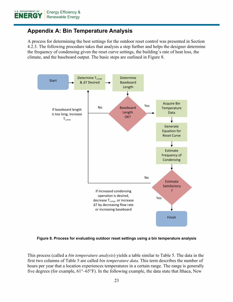
A process for determining the best settings for the outdoor reset control was presented in Section 4.2.3. The following procedure takes that analysis a step further and helps the designer determine the frequency of condensing given the reset curve settings, the building’s rate of heat loss, the climate, and the baseboard output. The basic steps are outlined in Figure 8.
Figure 8. Process for evaluating outdoor reset settings using a bin temperature analysis
This process (called a bin temperature analysis) yields a table similar to Table 5. The data in the first two columns of Table 5 are called bin temperature data. This term describes the number of hours per year that a location experiences temperatures in a certain range. The range is generally five degrees (for example, 61°–65°F). In the following example, the data state that Ithaca, New
Acquire Bin Temperature
Data
Generate Equation for Reset Curve
Baseboard Length
OK?
Yes
No
Estimate Frequency of Condensing
Determine Baseboard
Length
Determine Ts,max & ΔT Desired
Estimate Satisfactory
?
No Yes
Start
Finish
If baseboard length is too long, increase
Ts,max
If increased condensing operation is desired,
decrease Ts,max. or increase ΔT by decreasing flow rate
or increasing baseboard

24
York, experiences temperatures of 61°–65°F for 738 hours each year. These values are averages over many years of data and can be acquired for many locations across the country.
Table 5. Bin Analysis Results for a Project in Ithaca, New York
Bin Mean (°F)
Hours Supply Temp (°F)
Load (Btu/h)
Return Temp (°F)
ΔT (°F)
% of Heating Season
62 738 103.2 1066 101.1 2.1 11.1 57 715 110.0 1732 106.5 3.5 10.7 52 691 116.7 2398 111.9 4.8 10.4 47 643 123.5 3064 117.4 6.1 9.7 42 686 130.2 3730 122.8 7.5 10.3 37 776 137.0 4396 128.2 8.8 11.7 32 767 143.7 5062 133.6 10.1 11.5 27 507 150.5 5728 139.0 11.5 7.6 22 381 157.2 6395 144.4 12.8 5.7 17 297 164.0 7061 149.8 14.1 4.5 12 209 170.7 7727 155.3 15.5 3.1 7 119 177.5 8393 160.7 16.8 1.8 2 68 180.0 9059 161.9 18.1 1.0 –3 28 180.0 9725 160.5 19.5 0.4 –8 20 180.0 10391 159.2 20.8 0.3 –13 8 180.0 11057 157.9 22.1 0.1 –18 2 180.0 11723 156.5 23.5 0.0
Step 1. Acquire bin data
The first step in the process is to acquire bin temperature data which are available from a variety of sources. ASHRAE and the U.S. Air Force are two such sources. These data can also be acquired from several energy analysis software packages.
Step 2. Calculate the supply temperature based on the reset curve
The second step is to generate the equation for the reset curve so the supply temperature for each bin can be calculated. For this example, consider Figure 9, which shows a maximum boiler temperature of 180°F at 5°F outside and a minimum boiler supply temperature of 95°F at 68°F outside.

25
Figure 9. Boiler reset curve
The boiler supply temperature (Ts) is calculated using the boiler curve and the mean temperature for each bin (Tbin).
Ts = slope of the line × Tbin + Constant
Ts = (Ts,min-Ts,max)/(Tout,max-Tout,min) × Tbin + Constant
The only unknown, if we use design conditions to start, is C. To solve for C, substitute in the design conditions for Ts and Tbin: 180°F supply at 5°F outside.
This yields
180 = (95–180)/(68–5) × 5 + C
C = 180 – (–85/63) × 5 = 186.91
The general equation (for this reset curve) to input into the Supply Temp column is then:
Ts = –1.0345 × Tbin + 186.91
Step 3. Calculate the load for each bin
For this analysis, the building’s UA, or its rate of heat loss,
0
20
40
60
80
100
120
140
160
180
200
0 10 20 30 40 50 60 70 80
Supp
ly T
empe
ratu
re [F
]
Outside Temperature [F]
Boiler Reset Curve
A Building’s UA For this analysis, the building’s UA, or its rate of heat loss, can be calculated using the design load from the sizing calculation. The calculation is: Building UA = Design Load ÷ (Tin – Tout) Tin = assumed thermostat set point Tout = design temperature for your location

26
can be calculated using the design load from the sizing calculation.
UA = Design Load ÷ (Tin – Tout)
Tin = assumed thermostat set point
Tout = design temperature for your location
Use the UA from this calculation to calculate the load for each bin. The load for each bin temperature can be calculated by multiplying the UA by the difference between the indoor (Tin) and outdoor temperatures (Tbin).
Load = UA × Tin–Tbin
Step 4. Calculate the return temperature
Finally, assuming the flow rate through the zones is 1 gpm, the return temperature (Tr) is calculated as follows:
Tr = Ts – (Load/(gpm × 500))
Step 5. Determine % of the heating season system will condense
The % Heating Season column is simply the number of hours for that bin divided by the total number of hours in the table. Using this column and the Return Temp column, the frequency of condensing can be analyzed for Ts,max. Simply identify the return temperatures at or below 130°F and add up the % of the heating season for which that condition applies.
For example, in Table 5, the predicted frequency of condensing for these settings is approximately 64% of the heating season. This means that the boiler will likely be in condensing mode 64% of the heating season. It is NOT the predicted efficiency of the boiler.
27
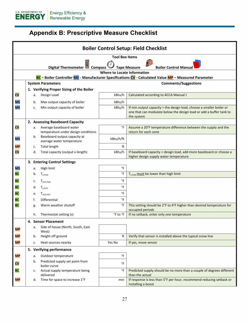
Appendix B: Prescriptive Measure Checklist
Boiler Control Setup: Field Checklist Tool Box Items
Digital Thermometer Compass Tape Measure Boiler Control Manual Where to Locate Information
BC – Boiler Controller MS - Manufacturer Specifications CV - Calculated Value MP – Measured Parameter System Parameters Comments/Suggestions 1. Verifying Proper Sizing of the Boiler CV a. Design Load kBtu/h Calculated according to ACCA Manual J
MS b. Max output capacity of boiler kBtu/h MS c. Min output capacity of boiler kBtu/h If min output capacity > the design load, choose a smaller boiler or
one that can modulate below the design load or add a buffer tank to the system
2. Assessing Baseboard Capacity CV a. Average baseboard water
temperature under design conditions °F Assume a 20°F temperature difference between the supply and the
return for each zone
MS b. Baseboard output capacity at average water temperature kBtu/h/ft
MP c. Total length ft CV d. Total capacity (output x length) kBtu/h If baseboard capacity < design load, add more baseboard or choose a
higher design supply water temperature 3. Entering Control Settings MS a. High limit °F BC b. Ts,max °F Ts,max must be lower than high limit
BC c. Tout,max °F
BC d. Ts,min °F
BC e. Tout,min °F
BC f. Differential °F BC g. Warm weather shutoff °F This setting should be 2°F to 4°F higher than desired temperature for
occupied periods h. Thermostat setting (s) °F to °F If no setback, enter only one temperature
4. Sensor Placement
MP a. Side of house (North, South, East West)
MP b. Height off ground ft Verify that sensor is installed above the typical snow line
MP c. Heat sources nearby Yes No If yes, move sensor
5. Verifying performance MP a. Outdoor temperature °F
CV b. Predicted supply set point from boiler curve °F
BC c. Actual supply temperature being delivered
°F Predicted supply should be no more than a couple of degrees different than the actual
MP d. Time for space to increase 1°F min If response is less than 5°F per hour, recommend reducing setback or installing a boost

28
6. Evaluating the Boost Control (if applicable)
CV a. Predicted supply set point from boiler curve °F
BC b. Lag time allowed min BC c. Intended temperature offset °F If the supply temperature did not increase after the lag time passed
and the thermostat is still calling for heat, recheck the settings in the boiler’s controller and consult the manufacturer’s installation guide.

DOE/GO-102013-3895 ▪ May 2013
Printed with a renewable-source ink on paper containing at least 50% wastepaper, including 10% post-consumer waste.