measurement and test report
TRANSCRIPT

Note: This test report is prepared for the customer shown above and for the device described herein. It may not be duplicated or used in part without prior written consent from Bay Area Compliance Laboratories Corp.(Shenzhen) This report must not be used by the customer to claim product certification, approval, or endorsement by NVLAP*, NIST, or any agency of the Federal Government.
EN 61000-6-3: 2007, EN 50130-4: 1995+A1: 1998+A2: 2003 EN 61000-3-2: 2006, EN 61000-3-3: 1995+A1: 2001+A2: 2005
MEASUREMENT AND TEST REPORT
For HENAN HANWEI ELECTRONICS CORPORATION LIMITED
No. 169, Xue Song Road, National Hi-Tech Zone, Zhengzhou 450001, China
Report Type:
Original Report
Product Type:
Gas Alarm
Test Engineer: Alex Huang, Peter Zhang
Report Number: RSC081150006a -1
Reviewed By: Name: David Li Title: BACL-Engineer
Prepared By:
Bay Area Compliance Laboratories Corp. (Shenzhen) 6/F, the 3rd Phase of WanLi Industrial Building, ShiHua Road, FuTian Free Trade Zone Shenzhen, Guangdong, China www.baclcorp.com
Model Number: KAB
HENAN HANWEI ELECTRONICS CORPORATION LIMITED Model Number: KAB
Report # RSC081150006a -1 Page 2 of 36 EN 61000-6-3, EN 50130-4 ; EN 61000-3-2; EN 61000-3-3 report
TABLE OF CONTENTS
GENERAL INFORMATION.......................................................................................................................................4
PRODUCT DESCRIPTION FOR EQUIPMENT UNDER TEST (EUT) ....................................................................................4 OBJECTIVE ...................................................................................................................................................................4 PERFORMANCE CRITERIA.............................................................................................................................................4 RELATED SUBMITTAL(S)/GRANT(S).............................................................................................................................4 TEST METHODOLOGY ..................................................................................................................................................4 TEST FACILITY.............................................................................................................................................................5
SYSTEM TEST CONFIGURATION..........................................................................................................................6 JUSTIFICATION .............................................................................................................................................................6 EUT EXERCISE SOFTWARE ..........................................................................................................................................6 SPECIAL ACCESSORIES.................................................................................................................................................6 BLOCK DIAGRAM/SCHEMATICS ...................................................................................................................................6 EQUIPMENT MODIFICATIONS .......................................................................................................................................6 EQUIPMENT UNDER TEST (EUT) GENERAL DESCRIPTION ...........................................................................................7 EXTERNAL I/O CABLE..................................................................................................................................................7 BLOCK DIAGRAM OF TEST SETUP ................................................................................................................................8
SUMMARY OF TEST RESULTS ...............................................................................................................................9
EN 61000-6-3 - CONDUCTED DISTURBANCE...................................................................................................10 MEASUREMENT UNCERTAINTY..................................................................................................................................10 EUT SETUP ................................................................................................................................................................10 EMI TEST RECEIVER SETUP.......................................................................................................................................11 TEST EQUIPMENT LIST AND DETAILS.........................................................................................................................11 TEST PROCEDURE ......................................................................................................................................................11 TEST RESULTS SUMMARY..........................................................................................................................................11 TEST DATA ................................................................................................................................................................12 PLOT(S) OF TEST DATA ..............................................................................................................................................13
EN 61000-6-3 - RADIATED DISTURBANCE..........................................................................................................15 MEASUREMENT UNCERTAINTY..................................................................................................................................15 EUT SETUP ................................................................................................................................................................15 EMI TEST RECEIVER SETUP.......................................................................................................................................16 TEST EQUIPMENT LIST AND DETAILS.........................................................................................................................16 TEST PROCEDURE ......................................................................................................................................................16 CORRECTED AMPLITUDE & MARGIN CALCULATION .................................................................................................16 TEST RESULTS SUMMARY..........................................................................................................................................16 TEST CURVES.............................................................................................................................................................17
EN 61000-3-2-HARMONIC CURRENT EMISSIONS ............................................................................................18 TEST EQUIPMENT.......................................................................................................................................................18 TEST SYSTEM SETUP..................................................................................................................................................18 TEST STANDARD ........................................................................................................................................................18 TEST DATA ................................................................................................................................................................18
EN 61000-3-3- VOLTAGE FLUCTUATION AND FLICKER...............................................................................19 TEST EQUIPMENT.......................................................................................................................................................19 TEST SYSTEM SETUP..................................................................................................................................................19 TEST STANDARD ........................................................................................................................................................19 TEST DATA ................................................................................................................................................................20
EN 50130-4 - ELECTROSTATIC DISCHARGES (EN61000-4-2).........................................................................21 TEST EQUIPMENT.......................................................................................................................................................21 TEST SYSTEM SETUP..................................................................................................................................................21 TEST STANDARD ........................................................................................................................................................21 TEST PROCEDURE ......................................................................................................................................................22

HENAN HANWEI ELECTRONICS CORPORATION LIMITED Model Number: KAB
Report # RSC081150006a -1 Page 3 of 36 EN 61000-6-3, EN 50130-4 ; EN 61000-3-2; EN 61000-3-3 report
TEST DATA ................................................................................................................................................................23
EN 50130-4 - CONTINOUS RADIATED DISTURBANCES (EN61000-4-3) .....................................................24 TEST EQUIPMENT.......................................................................................................................................................24 TEST SYSTEM SETUP..................................................................................................................................................24 TEST STANDARD ........................................................................................................................................................25 TEST PROCEDURE ......................................................................................................................................................25 TEST DATA ................................................................................................................................................................25
EN 50130-4 - ELECTRICAL FAST TRANSIENTS (EN61000-4-4).......................................................................26 TEST EQUIPMENT.......................................................................................................................................................26 TEST SYSTEM SETUP..................................................................................................................................................26 TEST STANDARD ........................................................................................................................................................26 TEST PROCEDURE ......................................................................................................................................................27 TEST DATA ................................................................................................................................................................27
EN 50130-4 - SURGES (EN61000-4-5) ......................................................................................................................28 TEST EQUIPMENT.......................................................................................................................................................28 TEST SYSTEM SETUP..................................................................................................................................................28 TEST STANDARD ........................................................................................................................................................28 TEST PROCEDURE ......................................................................................................................................................29 TEST DATA ................................................................................................................................................................29
EN 50130-4 - CONTINUOUS CONDUCTED DISTURBANCE.............................................................................30
(EN61000-4-6) ..............................................................................................................................................................30 TEST EQUIPMENT.......................................................................................................................................................30 TEST SYSTEM SETUP..................................................................................................................................................30 TEST STANDARD ........................................................................................................................................................30 TEST PROCEDURE ......................................................................................................................................................31 TEST DATA ................................................................................................................................................................31
EN 50130-4 - VOLTAGE DIPS AND INTERRUPTIONS (EN61000-4-11)...........................................................32 TEST EQUIPMENT.......................................................................................................................................................32 TEST SYSTEM SETUP..................................................................................................................................................32 TEST STANDARD ........................................................................................................................................................32 TEST PROCEDURE ......................................................................................................................................................33 TEST DATA ................................................................................................................................................................33
EXHIBIT A - PRODUCT LABELING .....................................................................................................................34 PROPOSED CE LABEL FORMAT ..................................................................................................................................34 PROPOSED LABEL LOCATION ON EUT .......................................................................................................................34 PRODUCT MANUAL....................................................................................................................................................34
EXHIBIT B - EUT PHOTOGRAPHS .......................................................................................................................35
HENAN HANWEI ELECTRONICS CORPORATION LIMITED Model Number: KAB
Report # RSC081150006a -1 Page 4 of 36 EN 61000-6-3, EN 50130-4 ; EN 61000-3-2; EN 61000-3-3 report
GENERAL INFORMATION Product Description for Equipment Under Test (EUT) The HENAN HANWEI ELECTRONICS CORPORATION LIMITED ’s product, Model number: KAB or the "EUT" as referred to in this report is the Gas Alarm, rated input voltage: AC 230V/50Hz. Objective The following test report is prepared on behalf of HENAN HANWEI ELECTRONICS CORPORATION LIMITED in accordance with EN 61000-6-3, EN 50130-4, EN 61000-3-2 and EN 61000-3-3. EN 61000-6-3: Electromagnetic compatibility (EMC) Part 6-3: Generic Standards — emission standard for residential, commercial and light-industrial equipments. EN 50130-4: Alarm system—Part 4: Electromagnetic compatibility (EMC) —product family standard: immunity requirements for components of fire, instruder and social alarm systems. EN 61000-3-2: Electromagnetic compatibility (EMC) Part 3-2: Limits for harmonic current emissions (equipment input current up to and including 16A phase). EN 61000-3-3: Electromagnetic compatibility (EMC) Part 3-2 Limitation of voltage changes, voltage fluctuations and flicker in public low-voltage supply systems, for equipment with rated current ≤16A per phase and subject to conditional connection. The objective of the manufacture is to determine compliance with EN 61000-6-3, EN 50130-4, EN 61000-3-2 and EN 61000-3-3. Performance Criteria
A. The apparatus shall continue to operate as intended during and after the test. The manufacturer specifies some minimum performance level. The performance level may be
specified by the manufacturer as a permissible loss of performance.
B. The apparatus shall continue to operate as intended after the test. This indicates that the EUT does not need to function at normal performance levels during the test, but must recover. Again some minimal performance is defined by the manufacture. No change in operating state or loss or data is permitted.
C. Temporary loss of function is allowed. Operation of the EUT may stop as long as it is either automatically reset or can be manually restored by operation of the controls.
Related Submittal(s)/Grant(s) No Related Submittals. Test Methodology All measurements contained in this report were conducted with CISPR 16-1 - radio disturbance and immunity measuring apparatus, and CISPR 16-2 - Method of measurement of disturbances and immunity.

HENAN HANWEI ELECTRONICS CORPORATION LIMITED Model Number: KAB
Report # RSC081150006a -1 Page 5 of 36 EN 61000-6-3, EN 50130-4 ; EN 61000-3-2; EN 61000-3-3 report
Test Facility The Test site used by Bay Area Compliance Laboratories Corp. (Shenzhen) to collect test data is located in the 6/F, the 3rd Phase of WanLi Industrial Building, ShiHua Road, FuTian Free Trade Zone Shenzhen, Guangdong, China. Test site at Bay Area Compliance Laboratories Corp. (Shenzhen) has been fully described in reports submitted to the Federal Communication Commission (FCC). The details of these reports have been found to be in compliance with the requirements of Section 2.948 of the FCC Rules on November 04, 2004. The facility also complies with the radiated and AC line conducted test site criteria set forth in ANSI C63.4-2003. The Federal Communications Commission has the reports on file and is listed under FCC Registration No.: 382179. The test site has been approved by the FCC for public use and is listed in the FCC Public Access Link (PAL) database. Additionally, Bay Area Compliance Laboratories Corp. (Shenzhen) is a National Institute of Standards and Technology (NIST) accredited laboratory, under the National Voluntary Laboratory Accredited Program (Lab Code 200707-0). The current scope of accreditations can be found at http://ts.nist.gov/ts/htdocs/210/214/scopes/2007070.htm.
HENAN HANWEI ELECTRONICS CORPORATION LIMITED Model Number: KAB
Report # RSC081150006a -1 Page 6 of 36 EN 61000-6-3, EN 50130-4 ; EN 61000-3-2; EN 61000-3-3 report
SYSTEM TEST CONFIGURATION Justification The system was configured for testing in a typical fashion (as normally used by a typical user). EUT Exercise Software N/A Special Accessories All interface cables used for compliance testing are shielded as normally supplied by the applicant and their respective support equipment manufacturers. Block Diagram/Schematics Please refer to the Exhibit C. Equipment Modifications Block diagram/schematic were not prepared by the applicant at time of test.

HENAN HANWEI ELECTRONICS CORPORATION LIMITED Model Number: KAB
Report # RSC081150006a -1 Page 7 of 36 EN 61000-6-3, EN 50130-4 ; EN 61000-3-2; EN 61000-3-3 report
Equipment Under Test (EUT) General Description
Applicant Description Model Number Serial Number FCC ID
HENAN HANWEI ELECTRONICS CORPORATION
LIMITED
Gas Alarm KAB N/A N/A
External I/O Cable
Cable Description Length (M) From/Port To
AC Power Cable 1.0 LISN EUT
HENAN HANWEI ELECTRONICS CORPORATION LIMITED Model Number: KAB
Report # RSC081150006a -1 Page 8 of 36 EN 61000-6-3, EN 50130-4 ; EN 61000-3-2; EN 61000-3-3 report
Block Diagram of Test Setup
1.5 Meters
Non-Conducting Table80 cm Above Ground Plane
1 M
eter
s
EUT
Power CablesDraped along the test table and
Bundled to 0.4m

HENAN HANWEI ELECTRONICS CORPORATION LIMITED Model Number: KAB
Report # RSC081150006a -1 Page 9 of 36 EN 61000-6-3, EN 50130-4 ; EN 61000-3-2; EN 61000-3-3 report
SUMMARY OF TEST RESULTS EN 61000-6-3, EN 61000-3-2 & EN 61000-3-3
Rule Description Result
EN 61000-6-3 Conducted Disturbance Compliant EN 61000-6-3 Radiated Disturbance Compliant EN 61000-3-2 Harmonic current Emissions Compliant EN 61000-3-3 Voltage Fluctuation and Flicker Compliant
EN 50130-4
Rule Description Result
Electrostatic Discharge EN 61000-4-2 Compliant Continuous Radiated Disturbance EN 61000-4-3 Compliant Electrical Fast Transients EN 61000-4-4 Compliant Surges EN 61000-4-5 Compliant Continuous Conducted Disturbance EN 61000-4-6 Compliant
EN 50130-4
Voltage Dips And Interruptions EN 61000-4-11 Compliant
HENAN HANWEI ELECTRONICS CORPORATION LIMITED Model Number: KAB
Report # RSC081150006a -1 Page 10 of 36 EN 61000-6-3, EN 50130-4 ; EN 61000-3-2; EN 61000-3-3 report
EN 61000-6-3 - CONDUCTED DISTURBANCE Measurement Uncertainty All measurements involve certain levels of uncertainties, especially in field of EMC. The factors contributing to uncertainties are EMI Test Receiver, cable loss, and L.I.S.N.. Based on NIS 81, The Treatment of Uncertainty in EMC Measurements, the best estimate of the uncertainty of any conducted emissions measurement at Bay Area Compliance Laboratories Corp. (Shenzhen) is +2.4 dB. EUT Setup The setup of EUT is according with CISPR 16-1, CISPR16-2 measurement procedure. The specification used was the EN 61000-6-3 limits. The external I/O cables and power cables were draped along the test table and formed a bundle 30 to 40 cm long in the middle. A 230V/50Hz power source was provided to EUT.
HENAN HANWEI ELECTRONICS CORPORATION LIMITED Model Number: KAB
Report # RSC081150006a -1 Page 11 of 36 EN 61000-6-3, EN 50130-4 ; EN 61000-3-2; EN 61000-3-3 report
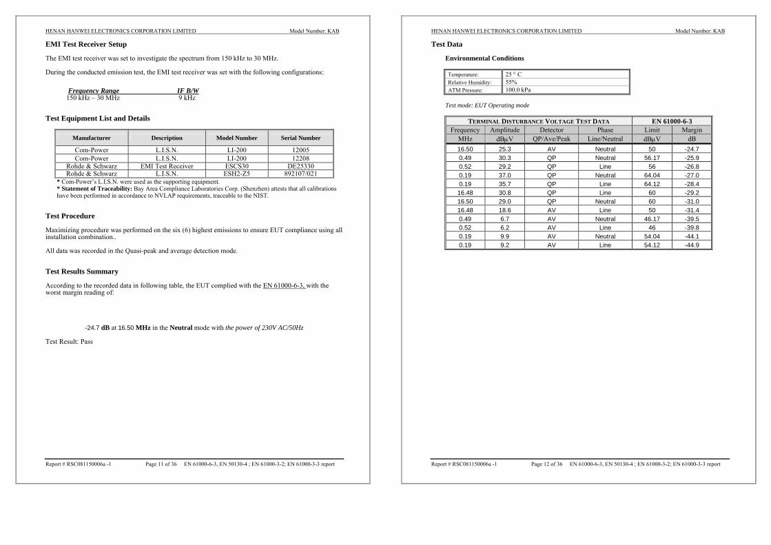
EMI Test Receiver Setup The EMI test receiver was set to investigate the spectrum from 150 kHz to 30 MHz. During the conducted emission test, the EMI test receiver was set with the following configurations:
Frequency Range IF B/W 150 kHz – 30 MHz 9 kHz
Test Equipment List and Details
Manufacturer Description Model Number Serial Number
Com-Power L.I.S.N. LI-200 12005 Com-Power L.I.S.N. LI-200 12208
Rohde & Schwarz EMI Test Receiver ESCS30 DE25330 Rohde & Schwarz L.I.S.N. ESH2-Z5 892107/021
* Com-Power’s L.I.S.N. were used as the supporting equipment. * Statement of Traceability: Bay Area Compliance Laboratories Corp. (Shenzhen) attests that all calibrations have been performed in accordance to NVLAP requirements, traceable to the NIST.
Test Procedure Maximizing procedure was performed on the six (6) highest emissions to ensure EUT compliance using all installation combination.. All data was recorded in the Quasi-peak and average detection mode. Test Results Summary According to the recorded data in following table, the EUT complied with the EN 61000-6-3, with the worst margin reading of:
-24.7 dB at 16.50 MHz in the Neutral mode with the power of 230V AC/50Hz
Test Result: Pass
HENAN HANWEI ELECTRONICS CORPORATION LIMITED Model Number: KAB
Report # RSC081150006a -1 Page 12 of 36 EN 61000-6-3, EN 50130-4 ; EN 61000-3-2; EN 61000-3-3 report
Test Data
Environmental Conditions
Temperature: 25 ° C Relative Humidity: 55% ATM Pressure: 100.0 kPa
Test mode: EUT Operating mode
TERMINAL DISTURBANCE VOLTAGE TEST DATA EN 61000-6-3 Frequency Amplitude Detector Phase Limit Margin
MHz dBμV QP/Ave/Peak Line/Neutral dBμV dB 16.50 25.3 AV Neutral 50 -24.7 0.49 30.3 QP Neutral 56.17 -25.9 0.52 29.2 QP Line 56 -26.8 0.19 37.0 QP Neutral 64.04 -27.0 0.19 35.7 QP Line 64.12 -28.4 16.48 30.8 QP Line 60 -29.2 16.50 29.0 QP Neutral 60 -31.0 16.48 18.6 AV Line 50 -31.4 0.49 6.7 AV Neutral 46.17 -39.5 0.52 6.2 AV Line 46 -39.8 0.19 9.9 AV Neutral 54.04 -44.1 0.19 9.2 AV Line 54.12 -44.9

HENAN HANWEI ELECTRONICS CORPORATION LIMITED Model Number: KAB
Report # RSC081150006a -1 Page 13 of 36 EN 61000-6-3, EN 50130-4 ; EN 61000-3-2; EN 61000-3-3 report
Plot(s) of Test Data Plot(s) of Test Data is presented hereinafter as reference.
HENAN HANWEI ELECTRONICS CORPORATION LIMITED Model Number: KAB
Report # RSC081150006a -1 Page 14 of 36 EN 61000-6-3, EN 50130-4 ; EN 61000-3-2; EN 61000-3-3 report

HENAN HANWEI ELECTRONICS CORPORATION LIMITED Model Number: KAB
Report # RSC081150006a -1 Page 15 of 36 EN 61000-6-3, EN 50130-4 ; EN 61000-3-2; EN 61000-3-3 report
EN 61000-6-3 - RADIATED DISTURBANCE Measurement Uncertainty All measurements involve certain levels of uncertainties, especially in field of EMC. The factors contributing to uncertainties are EMI Test Receiver, cable loss, antenna factor calibration, antenna directivity, antenna factor variation with height, antenna phase center variation, antenna factor frequency interpolation, measurement distance variation, site imperfections, mismatch (average), and system repeatability. Based on NIS 81, The Treatment of Uncertainty in EMC Measurements, the best estimate of the uncertainty of a radiation emissions measurement at Bay Area Compliance Laboratories Corp. (Shenzhen) is +4.0 dB. EUT Setup The radiated emission tests were performed in the 3 meters chamber B test site, using the setup accordance with the CISPR 16-1, CISPR 16-2. The specification used was EN 61000-6-3 limits. The external I/O cables and power cables were draped along the test table and formed a bundle 30 to 40 cm long in the middle. A 230V/50Hz power source was provided to EUT.
HENAN HANWEI ELECTRONICS CORPORATION LIMITED Model Number: KAB
Report # RSC081150006a -1 Page 16 of 36 EN 61000-6-3, EN 50130-4 ; EN 61000-3-2; EN 61000-3-3 report
EMI Test Receiver Setup The system was investigated from 30 MHz to 1000 MHz. During the radiated emission test, the EMI test receiver was set with the following configurations:
Frequency R B/W V B/W IF B/W 30 MHz-1 GHz 100 kHz 300 kHz 120 kHz
Test Equipment List and Details
Manufacturer Description Model Number Serial Number
HP Amplifier 8447E 1937A01046 Rohde & Schwarz EMI Test Receiver ESCI 100224
Sunol Sciences Bilog Antenna JB1 A040904-2 * Statement of Traceability: Bay Area Compliance Laboratories Corp. (Shenzhen) attests that all calibrations have been performed in accordance to NVLAP requirements, traceable to the NIST.
Test Procedure Maximizing procedure was performed on the highest emissions to ensure that the EUT complied with all installation combinations. All data was recorded in the Quasi-peak detection mode. Corrected Amplitude & Margin Calculation The Corrected Amplitude is calculated by adding the Antenna Loss and Cable Loss, and subtracting the Amplifier Gain from the Meter Reading. The basic equation is as follows:
Corr. Ampl. = Meter Reading + Antenna Loss + Cable Loss - Amplifier Gain The “Margin” column of the following data tables indicates the degree of compliance with the applicable limit. For example, a margin of 7dB means the emission is 7dB below the maximum limit. The equation for margin calculation is as follows:
Margin = Corr. Ampl - EN 61000-6-3 Limit Test Results Summary According to the test curves in the following, the EUT complied with the EN 61000-6-3, Test Result: pass

HENAN HANWEI ELECTRONICS CORPORATION LIMITED Model Number: KAB
Report # RSC081150006a -1 Page 17 of 36 EN 61000-6-3, EN 50130-4 ; EN 61000-3-2; EN 61000-3-3 report
Test Curves
Environmental Conditions
Temperature: 25 ° C Relative Humidity: 60% ATM Pressure: 100.2 kPa
Testing mode: operating mode
HENAN HANWEI ELECTRONICS CORPORATION LIMITED Model Number: KAB
Report # RSC081150006a -1 Page 18 of 36 EN 61000-6-3, EN 50130-4 ; EN 61000-3-2; EN 61000-3-3 report
EN 61000-3-2-HARMONIC CURRENT EMISSIONS Test Equipment
Manufacturer Description Model Number Serial Number
EM Test Harmonic/Flicker Analyzer DPA500 303278
EM Test AC Source ACS500 303276 * Statement of Traceability: Bay Area Compliance Laboratories Corp. (Shenzhen) attests that all calibrations have been performed in accordance to NVLAP requirements, traceable to the NIST.
Test System Setup Test Standard
EN 61000-3-2 Test Data Measurement file name: Harmonics_3_2
Standard used: EN 61000-3-2
Observation time: 150s
Windows width: 16 periods - (EN/IEC 61000-4-7 Edition 2002)
Customer: HENAN HANWEI ELECTRONICS CORPORATION LIMITED
E. U. T.: Gas Alarm
Model Number: KAB
Test Mode: Operating Mode The active input powe of this EUT is lower than 75W, Therefore, according to EN 61000-3-2, no limits are necessary. Test Result: pass
AC Mains
AC Source EUT
Wooden Table
0.8M
Analyzer

HENAN HANWEI ELECTRONICS CORPORATION LIMITED Model Number: KAB
Report # RSC081150006a -1 Page 19 of 36 EN 61000-6-3, EN 50130-4 ; EN 61000-3-2; EN 61000-3-3 report
EN 61000-3-3- VOLTAGE FLUCTUATION AND FLICKER Test Equipment
Manufacturer Description Model Number Serial Number
EM Test Harmonic/Flicker Analyzer DPA500 303278
EM Test AC Source ACS500 303276 * Statement of Traceability: Bay Area Compliance Laboratories Corp. (Shenzhen) attests that all calibrations have been performed in accordance to NVLAP requirements, traceable to the NIST.
Test System Setup Test Standard
EN 61000-3-3
AC Mains
AC Source EUT
Wooden Table
0.8M
Analyzer
HENAN HANWEI ELECTRONICS CORPORATION LIMITED Model Number: KAB
Report # RSC081150006a -1 Page 20 of 36 EN 61000-6-3, EN 50130-4 ; EN 61000-3-2; EN 61000-3-3 report
Test Data Standard used: EN 61000-3-3 Flicker
Short time (Pst): 10 min
Observation time: 10 min (1 Flicker measurement)
Flickermeter: 230V / 50Hz
Customer: HENAN HANWEI ELECTRONICS CORPORATION LIMITED
E. U. T.: Gas Alarm
Model Number: KAB
Test Mode: Operating Mode Test Result: pass

HENAN HANWEI ELECTRONICS CORPORATION LIMITED Model Number: KAB
Report # RSC081150006a -1 Page 21 of 36 EN 61000-6-3, EN 50130-4 ; EN 61000-3-2; EN 61000-3-3 report
EN 50130-4 - ELECTROSTATIC DISCHARGES (EN61000-4-2) Test Equipment
Manufacturer Description Model Number Serial Number
EM Test ESD Tester Dito 302105 * Statement of Traceability: Bay Area Compliance Laboratories Corp. (Shenzhen) attests that all calibrations have been performed in accordance to NVLAP requirements, traceable to the NIST.
Test System Setup EN 61000-4-2 specifies that a tabletop EUT shall be placed on a non-conducting table which is 80 centimeters above a ground reference plane and that floor mounted equipment shall be placed on a insulating support approximately 10 centimeters above a ground plane. During the tests, the EUT is positioned over a ground reference plane in conformance with this requirement. For tabletop equipment, a 1.5 by 1.0-meter metal sheet (HCP) is placed on the table and connected to the ground plane via a metal strap with two 470 k Ohms resistors in series. The EUT and attached cables are isolated from this metal sheet by 0.5-millimeter thick insulating material. A Vertical Coupling Plane (VCP) grounded on the ground plane through the same configuration as in the HCP is used. Test Standard
EN 50130-4 (EN 61000-4-2) Test level 3 for Air Discharge at ±8 kV Test level 2 for Contact Discharge at ±6 kV
Test level
Level Test Voltage
Contact Discharge (±kV) Test Voltage
Air Discharge (±kV) 1. 2 2 2. 4 4 3. 6 8 4. 8 15 X. Special Special
Performance criterion: A
AC Mains
EUT System
ESDTester
Wooden Table
Remark: is the tip of the electrode
0.8M
HENAN HANWEI ELECTRONICS CORPORATION LIMITED Model Number: KAB
Report # RSC081150006a -1 Page 22 of 36 EN 61000-6-3, EN 50130-4 ; EN 61000-3-2; EN 61000-3-3 report
Test Procedure
Air Discharge:
This test is done on a non-conductive surface. The round discharge tip of the discharge electrode shall be approached as fast as possible to touch the EUT. After each discharge, the discharge electrode shall be removed from the EUT. The generator is then re-triggered for a new single discharge and repeated 10 times for each pre-selected test point. This procedure shall be repeated until all the air discharge completed. Contact Discharge:
All the procedure shall be same as Section 8.3.1 of EN 61000-4-2, except that the tip of the discharge electrode shall touch the EUT before the discharge switch is operated. Indirect discharge for horizontal coupling plane
At least 20 single discharges shall be applied to the horizontal coupling plane, at points on each side of the EUT. The discharge electrode positions vertically at a distance of 0.1 m from the EUT and with the discharge electrode touching the coupling plane. Indirect discharge for vertical coupling plane
At least 20 single discharge shall be applied to the center of one vertical edge of the coupling plane. The coupling plane, of dimensions 0.5m X 0.5m, is placed parallel to, and positioned at a distance of 0.1m from the EUT. Discharges shall be applied to the coupling plane, with this plane in sufficient different positions that the four faces of the EUT are completely illuminated.

HENAN HANWEI ELECTRONICS CORPORATION LIMITED Model Number: KAB
Report # RSC081150006a -1 Page 23 of 36 EN 61000-6-3, EN 50130-4 ; EN 61000-3-2; EN 61000-3-3 report
Test Data
Environmental Conditions
Temperature: 25° C Relative Humidity: 58% ATM Pressure: 100.2 kPa
Test Mode: Operating mode Table 1: Electrostatic Discharge Immunity (Air Discharge)
Test Levels (kV) EN 61000-4-2
Test Points -2 +2 -4 +4 -6 +6 -8 +8 -15 +15Slots 20 Points A A A A A A A A / / buttons 2 points A A A A A A A A / / Leds 4 points A A A A A A A A Enclosure 40 Points A A A A A A A A / /
Table 2: Electrostatic Discharge Immunity (Direct Contact)
Test Levels (kV) EN 61000-4-2
Test Points -2 +2 -4 +4 -6 +6 -8 +8 -15 +15 Metal Part 10 Points A A A A A A / / / /
Table 3: Electrostatic Discharge Immunity (Indirect Contact HCP)
Test Levels (kV) EN 61000-4-2
Test Points -2 +2 -4 +4 -6 +6 -8 +8 -15 +15
Front Side A A A A A A / / / /
Back Side A A A A A A / / / /
Left Side A A A A A A / / / /
Right Side A A A A A A / / / / Table 4: Electrostatic Discharge Immunity (Indirect Contact VCP)
Test Levels (kV) EN 61000-4-2 Test Points -2 +2 -4 +4 -6 +6 -8 +8 -15 +15
Front Side A A A A A A / / / /
Back Side A A A A A A / / / /
Left Side A A A A A A / / / /
Right Side A A A A A A / / / /
Test Result: pass
HENAN HANWEI ELECTRONICS CORPORATION LIMITED Model Number: KAB
Report # RSC081150006a -1 Page 24 of 36 EN 61000-6-3, EN 50130-4 ; EN 61000-3-2; EN 61000-3-3 report
EN 50130-4 - CONTINOUS RADIATED DISTURBANCES (EN61000-4-3) Test Equipment
Manufacturer Description Model Serial Number
Amplifier Research Amplifier 150W1000 302657 Amplifier Research Field Meter FM5004 302149 Amplifier Research Sensor FP5000 301825
HP Signal Generator HP8657A 2849U00982 Sunol Sciences Broadband Antenna JB1 A040904-1
Giga-tronics Signal Generator 1026 270801 Sunol Sciences Horn Antenna DRH-118 A052604
* Statement of Traceability: Bay Area Compliance Laboratories Corp. (Shenzhen) attests that all calibrations have been performed in accordance to NVLAP requirements, traceable to the NIST.
Test System Setup Wooden table
3MetersEUT
System
0.8 Meter
Anechoic Chamber
Power Amp Signal Generator
HENAN HANWEI ELECTRONICS CORPORATION LIMITED Model Number: KAB
Report # RSC081150006a -1 Page 25 of 36 EN 61000-6-3, EN 50130-4 ; EN 61000-3-2; EN 61000-3-3 report
Test Standard
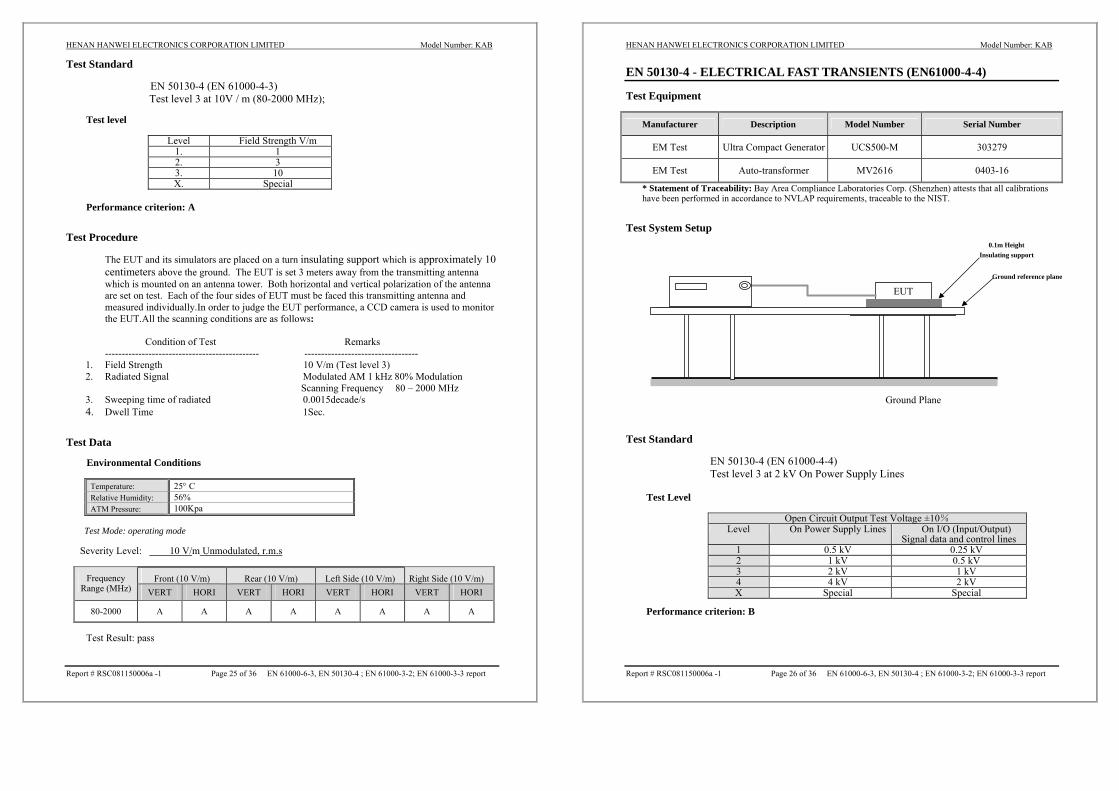
EN 50130-4 (EN 61000-4-3) Test level 3 at 10V / m (80-2000 MHz);
Test level
Level Field Strength V/m
1. 1 2. 3 3. 10 X. Special
Performance criterion: A
Test Procedure
The EUT and its simulators are placed on a turn insulating support which is approximately 10 centimeters above the ground. The EUT is set 3 meters away from the transmitting antenna which is mounted on an antenna tower. Both horizontal and vertical polarization of the antenna are set on test. Each of the four sides of EUT must be faced this transmitting antenna and measured individually.In order to judge the EUT performance, a CCD camera is used to monitor the EUT.All the scanning conditions are as follows:
Condition of Test Remarks ---------------------------------------------- ----------------------------------
1. Field Strength 10 V/m (Test level 3) 2. Radiated Signal Modulated AM 1 kHz 80% Modulation
Scanning Frequency 80 – 2000 MHz 3. Sweeping time of radiated 0.0015decade/s 4. Dwell Time 1Sec.
Test Data
Environmental Conditions
Temperature: 25° C Relative Humidity: 56% ATM Pressure: 100Kpa
Test Mode: operating mode
Severity Level: 10 V/m Unmodulated, r.m.s
Front (10 V/m) Rear (10 V/m) Left Side (10 V/m) Right Side (10 V/m) Frequency Range (MHz) VERT HORI VERT HORI VERT HORI VERT HORI
80-2000 A A A A A A A A
Test Result: pass
HENAN HANWEI ELECTRONICS CORPORATION LIMITED Model Number: KAB
Report # RSC081150006a -1 Page 26 of 36 EN 61000-6-3, EN 50130-4 ; EN 61000-3-2; EN 61000-3-3 report
EN 50130-4 - ELECTRICAL FAST TRANSIENTS (EN61000-4-4) Test Equipment
Manufacturer Description Model Number Serial Number
EM Test Ultra Compact Generator UCS500-M 303279
EM Test Auto-transformer MV2616 0403-16
* Statement of Traceability: Bay Area Compliance Laboratories Corp. (Shenzhen) attests that all calibrations have been performed in accordance to NVLAP requirements, traceable to the NIST.
Test System Setup Test Standard
EN 50130-4 (EN 61000-4-4) Test level 3 at 2 kV On Power Supply Lines
Test Level
Open Circuit Output Test Voltage ±10% Level On Power Supply Lines On I/O (Input/Output)
Signal data and control lines 1 0.5 kV 0.25 kV 2 1 kV 0.5 kV 3 2 kV 1 kV 4 4 kV 2 kV X Special Special
Performance criterion: B
EUT
Ground Plane
0.1m Height Insulating support
Ground reference plane

HENAN HANWEI ELECTRONICS CORPORATION LIMITED Model Number: KAB
Report # RSC081150006a -1 Page 27 of 36 EN 61000-6-3, EN 50130-4 ; EN 61000-3-2; EN 61000-3-3 report
Test Procedure The EUT was arranged for Power Line Coupling and for I/O Line Coupling through a capacitive clamp, where applicable. (Note: The I/O coupling test using a capacitive clamp is performed on the I/O interface cables that are longer in length than 3 meters.) A metal ground plane 2.4 meter by 2.0 meter was placed between the floor and the table and is connected to the earth by a 2.0 meter ground rod. The ground rod is connected to the test facility’s electrical earth. Test Data
Environmental Conditions
Temperature: 25 ° C Relative Humidity: 56% ATM Pressure: 100.2 kPa
Test Mode: operating mode
Test Levels (kV) EN 61000-4-4 Test Points +0. 5 -0. 5 +1.0 -1.0 +2.0 -2.0 +4.0 -4.0
L A A A A A A / /
N A A A A A A / /
PE A A A A A A / /
L+N A A A A A A / /
L+PE A A A A A A / /
N+PE A A A A A A / /
Power Supply
Power Line of EUT
PE+L+N A A A A A A / /
Signal ports / / / / / / / / Test Result: pass
HENAN HANWEI ELECTRONICS CORPORATION LIMITED Model Number: KAB
Report # RSC081150006a -1 Page 28 of 36 EN 61000-6-3, EN 50130-4 ; EN 61000-3-2; EN 61000-3-3 report
EN 50130-4 - SURGES (EN61000-4-5) Test Equipment
Manufacturer Description Model Number Serial Number
EM Test Ultra Compact Generator UCS500-M 303279
EM Test Auto-transformer MV2616 0403-16 * Statement of Traceability: Bay Area Compliance Laboratories Corp. (Shenzhen) attests that all calibrations
have been performed in accordance to NVLAP requirements, traceable to the NIST. Test System Setup Test Standard
EN 50130-4 (EN 61000-4-5) Line to Line: Test Level 2 at 1 kV Line to Ground: Test level 3 at 2 kV
Test Level
Level Open Circuit Output Test Voltage ±10% 1 0.5 kV 2 1 kV 3 2 kV 4 4 kV X Special
Performance criterion: B
EUT
Ground Plane
Ground reference plane

HENAN HANWEI ELECTRONICS CORPORATION LIMITED Model Number: KAB
Report # RSC081150006a -1 Page 29 of 36 EN 61000-6-3, EN 50130-4 ; EN 61000-3-2; EN 61000-3-3 report
Test Procedure
1) For line to line coupling mode, provide a 1 KV, Line to ground coupling mode, provide a 2
KV 1.2/50us voltage surge (at open-circuit condition). 2) At least 5 positive and 5 negative (polarity) tests with a maximum 1/min repetition rate are
conducted during test. 3) Different phase angles are done individually. 4) Record the EUT operating situation during compliance test and decide the EUT immunity
criterion for above each test. Test Data
Environmental Conditions
Temperature: 25 ° C Relative Humidity: 56% ATM Pressure: 100.2 kPa
Test Mode: Operating mode
Level Voltage Poll Path Pass Fail
1 0.5kV ± L-N, L-PE, N-PE A / 2 1kV ± L-N, L-PE, N-PE A / 3 2kV ± L-PE, N-PE A / 4 4kV ± L-N, L-PE, N-PE / /
Test Result: pass
HENAN HANWEI ELECTRONICS CORPORATION LIMITED Model Number: KAB
Report # RSC081150006a -1 Page 30 of 36 EN 61000-6-3, EN 50130-4 ; EN 61000-3-2; EN 61000-3-3 report
EN 50130-4 - CONTINUOUS CONDUCTED DISTURBANCE (EN61000-4-6) Test Equipment
Manufacturer Description Model Number Serial Number
EM CDN M3 303288 EM Test C/S Tester CWS500 303277 EM Test Attenuator 6dB 303282 EM Test Attenuator 6dB 303283
FCC Bulk Current Injection Probe F-120-9A 303284
* Statement of Traceability: Bay Area Compliance Laboratories Corp. (Shenzhen) attested that all calibrations have been performed in accordance to NVLAP requirements, traceable to the NIST. Test System Setup 0.1m Test Standard
EN 50130-4 (EN 61000-4-6) Test level 3 at 10 V (e.m.f.), 0.15 MHz ~ 100MHz,
Test Level
Level Voltage Level (e.m.f.) (V)
1 1 2 3 3 10 X Special
Performance criterion: A
Wooden TableSG
CDN
EUT

HENAN HANWEI ELECTRONICS CORPORATION LIMITED Model Number: KAB
Report # RSC081150006a -1 Page 31 of 36 EN 61000-6-3, EN 50130-4 ; EN 61000-3-2; EN 61000-3-3 report
Test Procedure
1) Let the EUT work in test mode and test it. 2) The EUT are placed on an insulating support 0.1 m high above a ground reference plane. CDN (coupling and decoupling device) is placed on the ground plane about 0.3 m from EUT. Cables between CDN and EUT are as short as possible, and their height above the ground reference plane shall be between 30 and 50 mm (where possible). 3) The disturbance signal described below is injected to EUT’s adapter through CDN. 4) The EUT operates within its operational mode(s) under intended climatic conditions after power on. 5) The frequency range is swept from 150 kHz to 100 MHz using 10V signal level, and with the disturbance signal 80% amplitude modulated with a 1KHz sine wave. 6) The rate of sweep shall not exceed 1.5*10-3decades/s. Where the frequency is swept incrementally, the step size shall not exceed 1% of the start and thereafter 1% of the preceding frequency value. 7) Recording the EUT operating situation during compliance testing and decide the EUT immunity criterion.
Test Data
Environmental Conditions
Temperature: 25 ° C Relative Humidity: 56% ATM Pressure: 100.0 kPa
Test mode: operating mode Frequency range: 150 kHz – 100 MHz, 150Ωsource impedance. Modulation: Amplitude, 80%, 1kHz sinusoidal; Pulse, 1Hz(0.5s ON; 0.5s OFF). Severity Level: 10Vrms
Level Voltage Level (e.m.f.) U0 Pass Fail
1 1 / / 2 3 / / 3 10 A / X Special / /
Test Result: pass
HENAN HANWEI ELECTRONICS CORPORATION LIMITED Model Number: KAB
Report # RSC081150006a -1 Page 32 of 36 EN 61000-6-3, EN 50130-4 ; EN 61000-3-2; EN 61000-3-3 report
EN 50130-4 - VOLTAGE DIPS AND INTERRUPTIONS (EN61000-4-11) Test Equipment
Manufacturer Description Model Number Serial Number
EM Test Ultra Compact Generator UCS500-M 303279
EM Test Auto-transformer MV2616 0403-16 * Statement of Traceability: Bay Area Compliance Laboratories Corp. (Shenzhen) attests that all calibrations have been performed in accordance to NVLAP requirements, traceable to the NIST.
Test System Setup Test Standard
EN 50130-4 (EN 61000-4-11) Test levels and Performance Criterion
Test Levels
Test Level % UT
Voltage dip and short interruptions
% UT
Duration (in periods)
0 100
40 60
70 30
0.5 1 5
10 25 50 X
Performance criterion: C & B
EUT
Ground Plane
Ground reference plane
HENAN HANWEI ELECTRONICS CORPORATION LIMITED Model Number: KAB
Report # RSC081150006a -1 Page 33 of 36 EN 61000-6-3, EN 50130-4 ; EN 61000-3-2; EN 61000-3-3 report
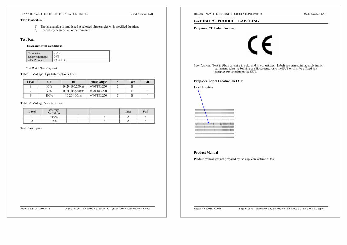
Test Procedure
1) The interruption is introduced at selected phase angles with specified duration. 2) Record any degradation of performance.
Test Data
Environmental Conditions
Temperature: 25 ° C Relative Humidity: 56% ATM Pressure: 100.0 kPa
Test Mode: Operating mode
Table 1: Voltage Tips/Interruptions Test
Level U2 td Phase Angle N Pass Fail 1 30% 10;20;100;200ms 0/90/180/270 3 B 2 60% 10;20;100;200ms 0/90/180/270 3 B / 3 100% 10;20;100ms 0/90/180/270 3 B /
Table 2: Voltage Variation Test
Level Voltage Variation Pass Fail
1 +10% / / A / 2 -15% / / A /
Test Result: pass
HENAN HANWEI ELECTRONICS CORPORATION LIMITED Model Number: KAB
Report # RSC081150006a -1 Page 34 of 36 EN 61000-6-3, EN 50130-4 ; EN 61000-3-2; EN 61000-3-3 report
EXHIBIT A - PRODUCT LABELING Proposed CE Label Format
Specifications: Text is Black or white in color and is left justified. Labels are printed in indelible ink on
permanent adhesive backing or silk-screened onto the EUT or shall be affixed at a conspicuous location on the EUT.
Proposed Label Location on EUT Label Location
Product Manual Product manual was not prepared by the applicant at time of test.

HENAN HANWEI ELECTRONICS CORPORATION LIMITED Model Number: KAB
Report # RSC081150006a -1 Page 35 of 36 EN 61000-6-3, EN 50130-4 ; EN 61000-3-2; EN 61000-3-3 report
EXHIBIT B - EUT PHOTOGRAPHS EUT FRONT VIEW EUT REAR VIEW
HENAN HANWEI ELECTRONICS CORPORATION LIMITED Model Number: KAB
Report # RSC081150006a -1 Page 36 of 36 EN 61000-6-3, EN 50130-4 ; EN 61000-3-2; EN 61000-3-3 report
EUT UNCOVERED VIEW 1 EUT UNCOVERED VIEW 2
*END OF REPORT