measurement of doppler radar signature of wind turbines at
TRANSCRIPT
ERAD 2012 - THE SEVENTH EUROPEAN CONFERENCE ON RADAR IN METEOROLOGY AND HYDROLOGY
Measurement of Doppler Radar Signature of wind turbines at high resolution in distance
Jean-Paul Marcellin1, Anil Cheraly2, Jean-François Petex3, Huy-Khang Phan4
1Office National d’Etudes et de Recherches Aérospatiales, Chemin de la Hunière BP 80100 FR-91123 PALAISEAU, France, [email protected]
2 France, [email protected] France, [email protected]
4 France, [email protected]
Jean-Paul Marcellin
1. Introduction
The number of large wind turbines installed in France is increasing. Their current or planned presence in areas monitored by radar systems involves the problem of their impact on the performance of these radars. To gain knowledge of this impact, Onera develops a computer simulator of radar interference by wind turbines, named "SiPRÉ" [1]. To validate some models implemented in this simulator, Onera uses a high resolution system named “MEDYCIS” particularly suitable to measure, Dynamic Radar Signature of wind turbines, in a range up to 20 km.
This poster presents and overview of the measurement system and some results obtained after a measurement campaign during October 2011:
• Doppler and high resolution Radar images of wind blades versus time. • Vertical profiles of electric field measured close to a wind turbine illuminated by MEDYCIS.
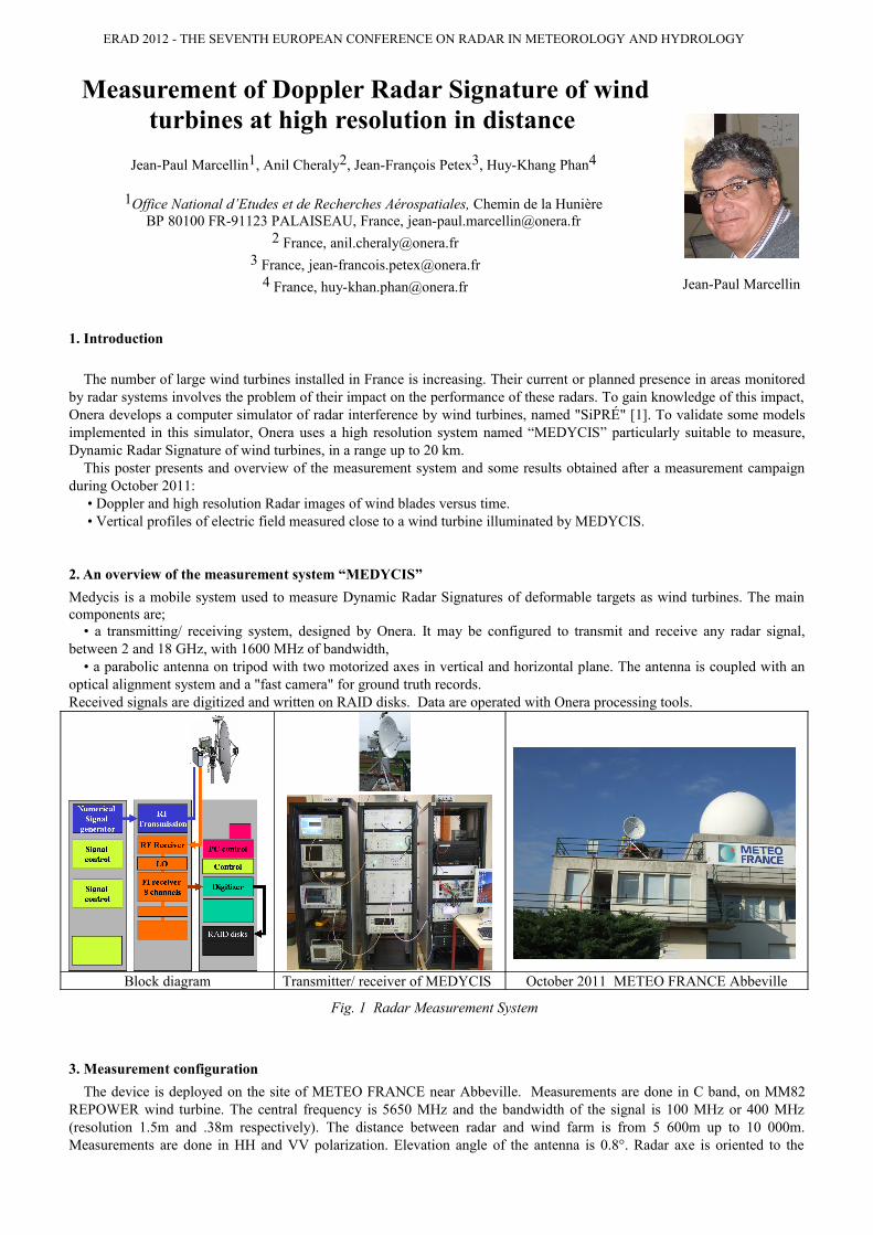
2. An overview of the measurement system “MEDYCIS”
Medycis is a mobile system used to measure Dynamic Radar Signatures of deformable targets as wind turbines. The main components are;
• a transmitting/ receiving system, designed by Onera. It may be configured to transmit and receive any radar signal, between 2 and 18 GHz, with 1600 MHz of bandwidth,
• a parabolic antenna on tripod with two motorized axes in vertical and horizontal plane. The antenna is coupled with an optical alignment system and a "fast camera" for ground truth records.Received signals are digitized and written on RAID disks. Data are operated with Onera processing tools.
Block diagram Transmitter/ receiver of MEDYCIS October 2011 METEO FRANCE Abbeville
Fig. 1 Radar Measurement System
3. Measurement configuration
The device is deployed on the site of METEO FRANCE near Abbeville. Measurements are done in C band, on MM82 REPOWER wind turbine. The central frequency is 5650 MHz and the bandwidth of the signal is 100 MHz or 400 MHz (resolution 1.5m and .38m respectively). The distance between radar and wind farm is from 5 600m up to 10 000m. Measurements are done in HH and VV polarization. Elevation angle of the antenna is 0.8°. Radar axe is oriented to the
ERAD 2012 - THE SEVENTH EUROPEAN CONFERENCE ON RADAR IN METEOROLOGY AND HYDROLOGY
nacelle. The transmitted power is 20W. Measurements are done in near field.Values of "dynamic RCS" are obtained by calibration of the received signal. We use a conducting sphere hung under a captive balloon. This experimental system looks like to the one used by AFRL in reference [2].
Calibration sphere
Antenna of MEDYCIS en C band configuration
Wind Farm of interest Fast Camera imageAxe radar- nacelle
Fig. 2 Measurement configuration
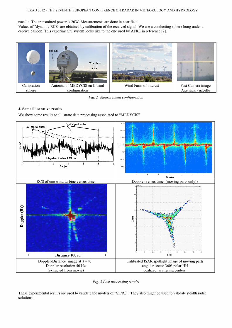
4. Some illustrative results
We show some results to illustrate data processing associated to “MEDYCIS”.
RCS of one wind turbine versus time Doppler versus time (moving parts only))
Doppler-Distance image at t = t0 Doppler resolution 40 Hz(extracted from movie)
Calibrated ISAR spotlight image of moving partsangular sector 360° polar HHlocalized scattering centers
Fig. 3 Post processing results
These experimental results are used to validate the models of “SiPRÉ”. They also might be used to validate stealth radar solutions.

ERAD 2012 - THE SEVENTH EUROPEAN CONFERENCE ON RADAR IN METEOROLOGY AND HYDROLOGY
4. Electromagnetic field measured near a wind turbine, created by radar illumination
The wind turbine is illuminated by a continuous monochromatic vertical polarized wave. The wind turbine is 5600 m far from the transmitting antenna. Antenna axe is oriented to the nacelle of the wind turbine. The electrical field near the wind turbine is measured on vertical lines between 5m and 160 m high, by step of 2m. Figure n°4 shows experimental results and computed results from simulator “SiPRÉ”.
Receiving antenna
Fig. 4 Computed and experimental results of vertical profile of electrical field created by radar illumination
4. Conclusion
This poster presents some results obtained by the experimental system "Medycis", designed and used by Onera to characterize Dynamic Radar Signatures of various targets such as wind turbines or sea clutter. Comparisons with modeling work (SiPRÉ) are on way.
Acknowledgment
Onera wants to thank METEO FRANCE to its welcome on site METEO FRANCE in ABBEVILLE, and its cooperation during the measurements campaign
Onera wants to thank REPOWER FRANCE who gave some technical information about the tested wind turbines.
References
[1] G Bobillot, J-P Marcellin, S. Langlet, A. Cheraly, J-F Petex, H.K. Phan, E. Chaumette, P. Fargette, N. Douchin, L. Rasoanaivo, 2012 , ONERA report RF 1/6790 DEMR
[2] Brian M. Kent, Kueichien C. Hill, Alan Buterba ugh, Greg Zelinskil, Robert Hawley, Lisa Cravens, Tni-Van, Christopher Vogee, Thomas Coveyou., 2008, Dynamic Radar Cross Section and Radar Doppler Measurements of Commercial General Electric Windmill Power Turbines Part 1: Predicted and Measured Radar Signatures. IEEE Antennas and Propagation Magazine, vol 50 n°2, 211-219.
Isotropic Receiving antenna