measuring utility pole heights and attachment points …€¦ · the ikegps™ provides a quick and...
TRANSCRIPT

AbstractThe ikeGPS™ provides a quick and auditable method of measuring the height and spacing of utility pole attachment points. The ikeGPS™ camera system’s performance is evaluated for measuring the attachment points on utility poles.
Accuracy is found to be better than 2% of the height measured, which equates to 3/16” over a typical communications cable vertical separation of 15”.
Measuring Utility Pole Heights and
Attachment Points with ikeGPS™
P O L E H E I G H T S & AT TA C H M E N T P O I N T S
Leon ToorenburgChief Technical Officer
ikeGPS™
Karl Nicholas Director Sales Support Services
ikeGPS™ Americas
Traditional Measuring – Hot StickThe traditional method of measuring pole attachment heights in the telecom and power utility markets has been an extendable fibreglass measuring pole (hot stick) that is raised to touch each point of interest on the pole, and the height written down. This method has a few challenges in the real world:
• The base reference point can move over the course of several measurements
• Curving of the measuring pole around objects adds unknown errors
• When looking straight up it can be difficult locating the precise attachment point of different services
• Measuring poles wear out
• No verification of the work done
• Limited to a certain height
• Potential contact with high voltages
• Must know exactly what you need to measure on the pole when you are in the field
• Must also keep an eye on the road while holding and concentrating on the pole
An ideal system would quickly record all the information on the pole, provide evidence of the work done, and allow other measurements to be made, avoiding the need to revisit the pole at a later date.
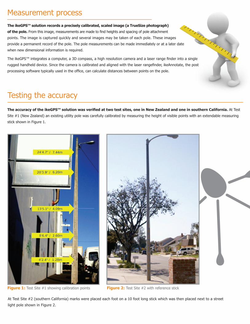
Measurement processThe ikeGPS™ solution records a precisely calibrated, scaled image (a TrueSize photograph)
of the pole. From this image, measurements are made to find heights and spacing of pole attachment
points. The image is captured quickly and several images may be taken of each pole. These images
provide a permanent record of the pole. The pole measurements can be made immediately or at a later date
when new dimensional information is required.
The ikeGPS™ integrates a computer, a 3D compass, a high resolution camera and a laser range finder into a single
rugged handheld device. Since the camera is calibrated and aligned with the laser rangefinder, ikeAnnotate, the post
processing software typically used in the office, can calculate distances between points on the pole.
Testing the accuracy
The accuracy of the ikeGPS™ solution was verified at two test sites, one in New Zealand and one in southern California. At Test
Site #1 (New Zealand) an existing utility pole was carefully calibrated by measuring the height of visible points with an extendable measuring
stick shown in Figure 1.
At Test Site #2 (southern California) marks were placed each foot on a 10 foot long stick which was then placed next to a street
light pole shown in Figure 2.
Figure 1: Test Site #1 showing calibration points Figure 2: Test Site #2 with reference stick

Measurement process
At Site #2, 62 images where collected using the ikeGPS™ with ikeCapture in TrueSize mode. The ikeGPS™ was located at various distances and
various angles from the target street light. For some images only the reference stick was included in the image, for the rest of the images the entire
street light pole was included in the TrueSize image. Forty of these images were captured with the ikeGPS™ mounted on a tripod and 22 images
were captured with the ikeGPS™ being handheld. After collecting the images, ikeAnnotate was used to mark the pole base, each 2 foot mark on the
reference stick, the base of the pole cap and the top of the pole. Figure 4 shows a typical annotated image of the street light pole at Site 2.
At site #1, 12 images were collected using the ikeGPS™ with ikeCapture in TrueSize mode. The ikeGPS™ was located approximately 20 metres (60ft)
from the pole and at various angles. Where possible, the entire pole was included in the captured image. The images collected were processed using
ikeAnnotate, by marking the location in the image of the pole base and each reference point. A typical annotated image shown in Figure 3.
Figure 3: Typical annotated image from Site #1
The results are summarized in the following table:
Ref Height 7.44 6.2 4.09 2.6 1.28
Average 0.04 0.04 0.02 0.00 0.00
Min -0.03 -0.01 -0.01 -0.02 -0.01
Max 0.10 0.09 0.05 0.01 0.00
Standard Dev. 0.03 0.03 0.02 0.01 0.00
RMS 0.05 0.05 0.03 0.01 0.01
RMS % 0.67% 0.76% 0.63% 0.33% 0.39%
Site #1: Error from Actual (meters) handheld ikeGPS™
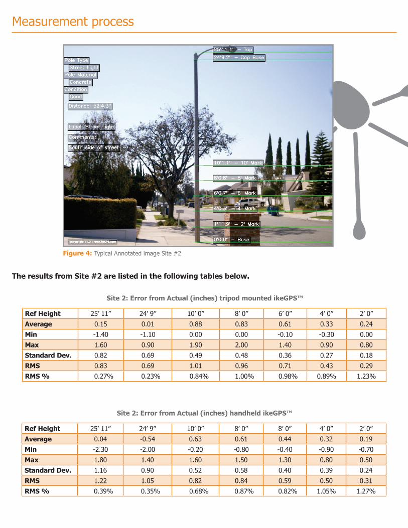
Figure 4: Typical Annotated image Site #2
The results from Site #2 are listed in the following tables below.
Ref Height 25’ 11” 24’ 9” 10’ 0” 8’ 0” 6’ 0” 4’ 0” 2’ 0”
Average 0.15 0.01 0.88 0.83 0.61 0.33 0.24
Min -1.40 -1.10 0.00 0.00 -0.10 - 0.30 0.00
Max 1.60 0.90 1.90 2.00 1.40 0.90 0.80
Standard Dev. 0.82 0.69 0.49 0.48 0.36 0.27 0.18
RMS 0.83 0.69 1.01 0.96 0.71 0.43 0.29
RMS % 0.27% 0.23% 0.84% 1.00% 0.98% 0.89% 1.23%
Site 2: Error from Actual (inches) tripod mounted ikeGPS™
Measurement process
Ref Height 25’ 11” 24’ 9” 10’ 0” 8’ 0” 8’ 0” 4’ 0” 2’ 0”
Average 0.04 -0.54 0.63 0.61 0.44 0.32 0.19
Min -2.30 -2.00 -0.20 -0.80 -0.40 - 0.90 - 0.70
Max 1.80 1.40 1.60 1.50 1.30 0.80 0.50
Standard Dev. 1.16 0.90 0.52 0.58 0.40 0.39 0.24
RMS 1.22 1.05 0.82 0.84 0.59 0.50 0.31
RMS % 0.39% 0.35% 0.68% 0.87% 0.82% 1.05% 1.27%
Site 2: Error from Actual (inches) handheld ikeGPS™

AnalysisThe ikeGPS™ in conjunction with ikeAnnotate used photogrammetry techniques to measure distances on the target pole.
As shown in the above tables, the absolute error (difference between the measured value and the actual value) increases
as the measured distance on the pole increases. So the height estimation of the entire pole will have a greater absolute
uncertainty than a shorter distance, but the error as a percentage of distance measured is lower at larger distances. The
results above show a maximum RMS error as a percentage of height (distance) measured of ±1.27%. Since other factors
can add error to the measurements (for example, if the pole is not vertical), to be on the safe side, let’s assume a ±2%
RMS error in this measurement scenario. For a 10m (30ft) pole this is a ±0.2m (±8 inches) error. For typical conductor
spacing measurements of 15 inches the error would be .3 (about 5/16) of an inch.
In summary, attachment height measurements made using the ikeGPS™ and ikeAnnotate, will typically
have an error less than 2% of the height being measured and in many cases the error will be less than 1%
of the height being measured. This accuracy assumes that proper procedures were followed using the ikeGPS™ when
capturing TrueSize images and when using ikeAnnotate to mark the attachments points on the TrueSize image.
Tips for getting the best ikeGPS pole height measurements
The most accurate pole height measurements are obtained when the proper procedures are used both in the field when capturing TrueSize images and
in the office when marking attachment points using ikeAnnotate. Here are some tips for capturing TrueSize images and annotating those images:
ikeGPS™ Tips for capturing quality TrueSize images:
• Get close enough to pole so that the area of interest fills as much of the ikeGPS™ screen as possible. This will insure maximum
resolution for ikeAnnotate. Remember, the TrueSize capture mode does not have a camera zoom; your feet are the zoom function.
• Review each image before saving, making sure that the entire area of interest in visible on the screen. Check the “Display
until user confirms” box in the Camera tab in ike Settings, then you can review each image and retry those images that are not aligned
properly on the screen.
• Have the pole lined up with the vertical cross hairs on the ikeGPS™ screen.
• Wherever possible have the sun behind or above you to best illuminate the pole. This will make it easier to see the attachment
points in ikeAnnotate. Don’t shot into the sun as the sun’s glare in the image makes it difficult to locate the attachment points.
• Make sure the distance to the pole is correct. Get in the habit of panning the ikeGPS™ across the target to determine the actual
distance to the target pole. When reviewing the image, make sure the distance is correct and you are not targeting tree branches in front
of the pole or objects behind the pole.
• Hold the ikeGPS™ steady when capturing TrueSize images. Any movement of the ikeGPS™ will result in a slightly blurry image, making
to more difficult to locate the attachment points on the image. When you are hot, sweaty and the bugs are biting you, it is understandable that
you are in a hurry. Taking another couple of seconds getting a quality TrueSize image will save hours of additional work.
• Take multiple images of a single pole, especially if the pole has a lot of attachments or vegetation around it.

Tips for getting the best ikeGPS™ pole height measurements cont.
ikeGPS Americas Contact Richard Taylor Office: (281) 681 0356 [email protected]
For more information or to purchase an ikeGPS™, Contact your regional ikeGPS Partner for sales information.
ikeGPS EMEA Contact Chris Jackson Office: +44 1962 711 473 [email protected]
ikeGPS Asia, Australasia Contact Leon Toorenburg Office: +64 4 382 8064 [email protected]
ikeAnnotate Tips
• Be consistent – apply the same standards for locating each attachment point on a pole image. For example, don’t use the bottom of the
marker line in ikeAnnotate to mark the base and the top of the line to mark the attachment point.
• Use the up/down arrows to fine tune the position the marker line after placing the marker line with the cursor.
• If you need to save several different annotated images of the original TrueSize image, give each annotated image a different label name.
Measuring an obstructed poleWhen it’s not possible to see the base of the pole, perhaps there is a fence or tree in the way, a marker of known height can be put up against
the pole and used as a base offset marker. Using an offset also allows more detail to be recorded of the top of the pole, since the ikeGPS™ will
be positioned closer to the pole. This annotated image was captured using 14 foot base offset marker.
Figure 5: Annotated image with base offset