mecc alte: روتارنژ perkins : لزید روتوم · photographs are for illustrative...
TRANSCRIPT
1
ABYARAN Copyright © 2014 - All Rights Reserved
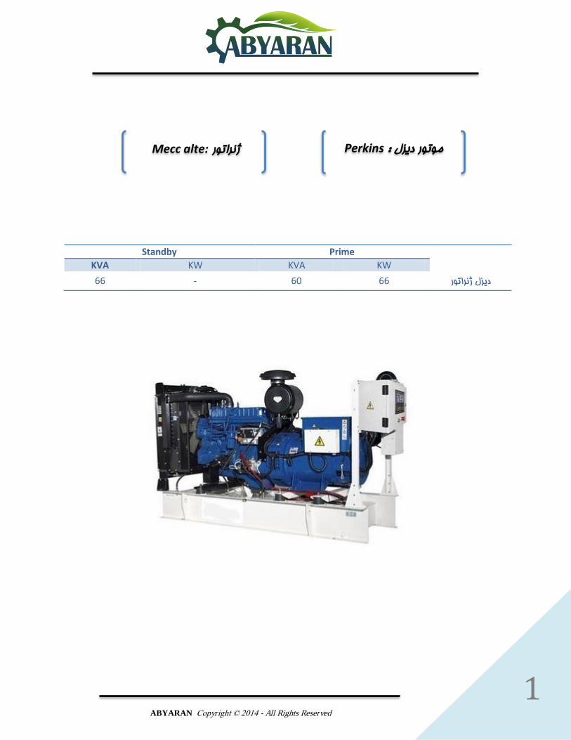
Standby Prime
KVA KW KVA KW
دیزل ژنراتور 66 60 - 66
:Mecc alte ژنراتور Perkinsموتور دیزل :
Photographs are for illustrative purposes only and may not reflect final specification.
All information in this document is substantially correct at time of printing and may be altered subsequently. Publication No. PN1878/09/12 Produced in England ©2012 Perkins Engines Company Limited
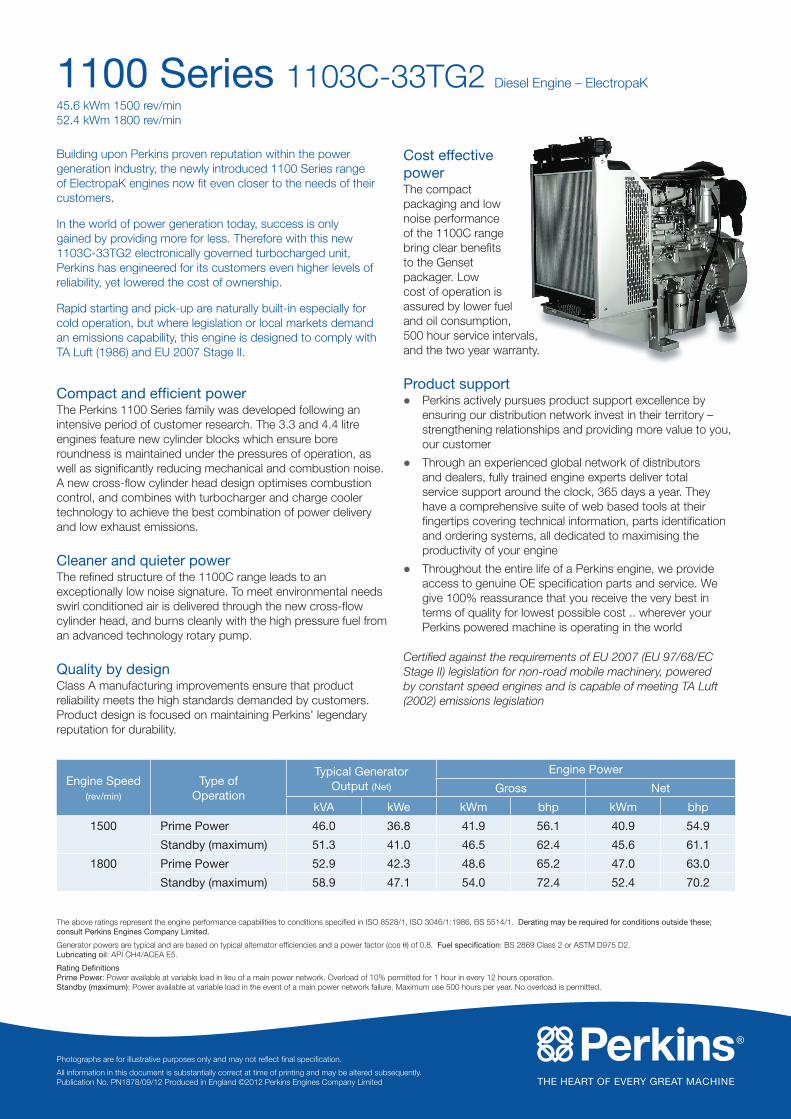
1100 Series 1103C-33TG2 Diesel Engine – ElectropaK
45.6 kWm 1500 rev/min 52.4 kWm 1800 rev/min
Building upon Perkins proven reputation within the power generation industry, the newly introduced 1100 Series range of ElectropaK engines now fit even closer to the needs of their customers.
In the world of power generation today, success is only gained by providing more for less. Therefore with this new 1103C-33TG2 electronically governed turbocharged unit, Perkins has engineered for its customers even higher levels of reliability, yet lowered the cost of ownership.
Rapid starting and pick-up are naturally built-in especially for cold operation, but where legislation or local markets demand an emissions capability, this engine is designed to comply with TA Luft (1986) and EU 2007 Stage II.
Compact and efficient powerThe Perkins 1100 Series family was developed following an intensive period of customer research. The 3.3 and 4.4 litre engines feature new cylinder blocks which ensure bore roundness is maintained under the pressures of operation, as well as significantly reducing mechanical and combustion noise. A new cross-flow cylinder head design optimises combustion control, and combines with turbocharger and charge cooler technology to achieve the best combination of power delivery and low exhaust emissions.
Cleaner and quieter powerThe refined structure of the 1100C range leads to an exceptionally low noise signature. To meet environmental needs swirl conditioned air is delivered through the new cross-flow cylinder head, and burns cleanly with the high pressure fuel from an advanced technology rotary pump.
Quality by designClass A manufacturing improvements ensure that product reliability meets the high standards demanded by customers. Product design is focused on maintaining Perkins’ legendary reputation for durability.
Cost effective powerThe compact packaging and low noise performance of the 1100C range bring clear benefits to the Genset packager. Low cost of operation is assured by lower fuel and oil consumption, 500 hour service intervals, and the two year warranty.
Product supportl Perkins actively pursues product support excellence by
ensuring our distribution network invest in their territory – strengthening relationships and providing more value to you, our customer
l Through an experienced global network of distributors and dealers, fully trained engine experts deliver total service support around the clock, 365 days a year. They have a comprehensive suite of web based tools at their fingertips covering technical information, parts identification and ordering systems, all dedicated to maximising the productivity of your engine
l Throughout the entire life of a Perkins engine, we provide access to genuine OE specification parts and service. We give 100% reassurance that you receive the very best in terms of quality for lowest possible cost .. wherever your Perkins powered machine is operating in the world
Certified against the requirements of EU 2007 (EU 97/68/EC Stage II) legislation for non-road mobile machinery, powered by constant speed engines and is capable of meeting TA Luft (2002) emissions legislation
Engine Speed(rev/min)
Type of Operation
Typical GeneratorOutput (Net)
Engine Power
Gross Net
kVA kWe kWm bhp kWm bhp
1500 Prime Power 46.0 36.8 41.9 56.1 40.9 54.9
Standby (maximum) 51.3 41.0 46.5 62.4 45.6 61.1
1800 Prime Power 52.9 42.3 48.6 65.2 47.0 63.0
Standby (maximum) 58.9 47.1 54.0 72.4 52.4 70.2
The above ratings represent the engine performance capabilities to conditions specified in ISO 8528/1, ISO 3046/1:1986, BS 5514/1. Derating may be required for conditions outside these; consult Perkins Engines Company Limited.
Generator powers are typical and are based on typical alternator efficiencies and a power factor (cos q) of 0.8. Fuel specification: BS 2869 Class 2 or ASTM D975 D2. Lubricating oil: API CH4/ACEA E5.
Rating Definitions Prime Power: Power available at variable load in lieu of a main power network. Overload of 10% permitted for 1 hour in every 12 hours operation. Standby (maximum): Power available at variable load in the event of a main power network failure. Maximum use 500 hours per year. No overload is permitted.
Photographs are for illustrative purposes only and may not reflect final specification.
All information in this document is substantially correct at time of printing and may be altered subsequently. Publication No. PN1878/09/12 Produced in England ©2012 Perkins Engines Company Limited
Perkins Engines Company LimitedPeterborough PE1 5FQ United Kingdom Telephone +44 (0)1733 583000 Fax +44 (0)1733 582240www.perkins.com
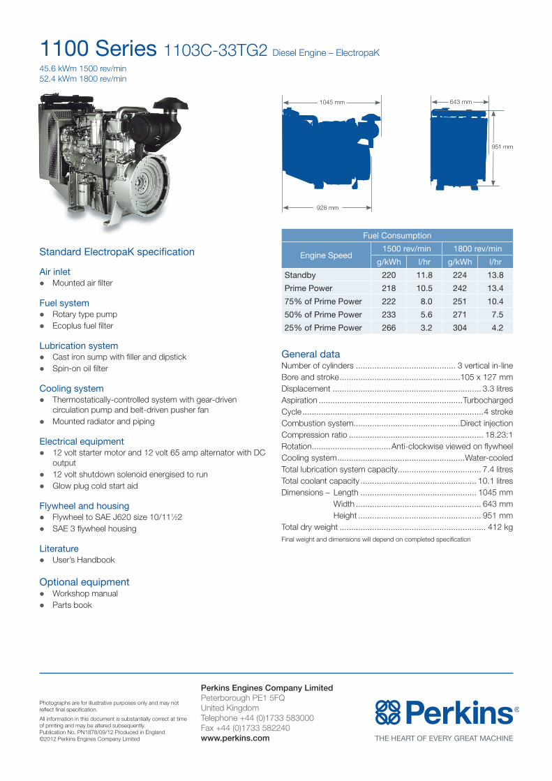
1100 Series 1103C-33TG2 Diesel Engine – ElectropaK
45.6 kWm 1500 rev/min 52.4 kWm 1800 rev/min
Standard ElectropaK specification
Air inletl Mounted air filter
Fuel systeml Rotary type pumpl Ecoplus fuel filter
Lubrication systeml Cast iron sump with filler and dipstickl Spin-on oil filter
Cooling systeml Thermostatically-controlled system with gear-driven
circulation pump and belt-driven pusher fanlMounted radiator and piping
Electrical equipmentl 12 volt starter motor and 12 volt 65 amp alternator with DC
outputl 12 volt shutdown solenoid energised to runlGlow plug cold start aid
Flywheel and housingl Flywheel to SAE J620 size 10/111⁄22l SAE 3 flywheel housing
Literaturel User’s Handbook
Optional equipmentlWorkshop manuall Parts book
General dataNumber of cylinders ........................................... 3 vertical in-lineBore and stroke ....................................................105 x 127 mm Displacement ................................................................ 3.3 litresAspiration ..............................................................TurbochargedCycle ..............................................................................4 strokeCombustion system ..............................................Direct injectionCompression ratio .......................................................... 18.23:1Rotation ..................................Anti-clockwise viewed on flywheelCooling system .......................................................Water-cooledTotal lubrication system capacity.................................... 7.4 litresTotal coolant capacity .................................................. 10.1 litresDimensions – Length .................................................. 1045 mm Width ...................................................... 643 mm Height ..................................................... 951 mmTotal dry weight ............................................................... 412 kgFinal weight and dimensions will depend on completed specification
Fuel Consumption
Engine Speed1500 rev/min 1800 rev/min
g/kWh l/hr g/kWh l/hr
Standby 220 11.8 224 13.8
Prime Power 218 10.5 242 13.4
75% of Prime Power 222 8.0 251 10.4
50% of Prime Power 233 5.6 271 7.5
25% of Prime Power 266 3.2 304 4.2
928 mm
951 mm
643 mm1045 mm
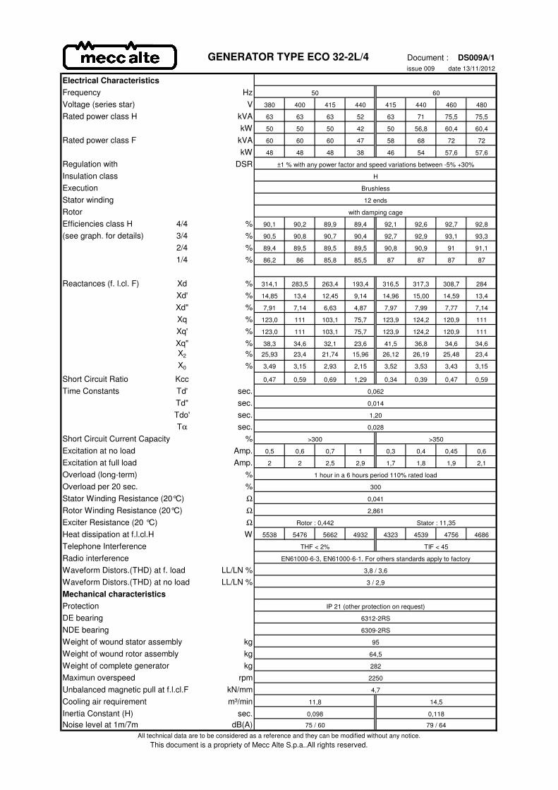
GENERATOR TYPE ECO 32-2L/4 Document : DS009A/1issue 009 date 13/11/2012
Electrical CharacteristicsFrequency Hz 50 60
Voltage (series star) V 380 400 415 440 415 440 460 480
Rated power class H kVA 63 63 63 52 63 71 75,5 75,5
kW 50 50 50 42 50 56,8 60,4 60,4
Rated power class F kVA 60 60 60 47 58 68 72 72
kW 48 48 48 38 46 54 57,6 57,6
Regulation with DSR ±1 % with any power factor and speed variations between -5% +30%
Insulation class H
Execution Brushless
Stator winding 12 ends
Rotor with damping cage
Efficiencies class H 4/4 % 90,1 90,2 89,9 89,4 92,1 92,6 92,7 92,8
(see graph. for details) 3/4 % 90,5 90,8 90,7 90,4 92,7 92,9 93,1 93,3
2/4 % 89,4 89,5 89,5 89,5 90,8 90,9 91 91,1
1/4 % 86,2 86 85,8 85,5 87 87 87 87
Reactances (f. l.cl. F) Xd % 314,1 283,5 263,4 193,4 316,5 317,3 308,7 284
Xd' % 14,85 13,4 12,45 9,14 14,96 15,00 14,59 13,4
Xd" % 7,91 7,14 6,63 4,87 7,97 7,99 7,77 7,14
Xq % 123,0 111 103,1 75,7 123,9 124,2 120,9 111
Xq' % 123,0 111 103,1 75,7 123,9 124,2 120,9 111
Xq" % 38,3 34,6 32,1 23,6 41,5 36,8 34,6 34,6
X2 % 25,93 23,4 21,74 15,96 26,12 26,19 25,48 23,4
X0 % 3,49 3,15 2,93 2,15 3,52 3,53 3,43 3,15
Short Circuit Ratio Kcc 0,47 0,59 0,69 1,29 0,34 0,39 0,47 0,59
Time Constants Td' sec.Td" sec.Tdo' sec.Tα sec.
Short Circuit Current Capacity % >300 >350
Excitation at no load Amp. 0,5 0,6 0,7 1 0,3 0,4 0,45 0,6
Excitation at full load Amp. 2 2 2,5 2,9 1,7 1,8 1,9 2,1
Overload (long-term) %Overload per 20 sec. %Stator Winding Resistance (20°C) ΩRotor Winding Resistance (20°C) ΩExciter Resistance (20 °C) ΩHeat dissipation at f.l.cl.H W 5538 5476 5662 4932 4323 4539 4756 4686
Telephone InterferenceRadio interferenceWaveform Distors.(THD) at f. load LL/LN %Waveform Distors.(THD) at no load LL/LN %Mechanical characteristicsProtectionDE bearingNDE bearingWeight of wound stator assembly kgWeight of wound rotor assembly kgWeight of complete generator kgMaximun overspeed rpmUnbalanced magnetic pull at f.l.cl.F kN/mmCooling air requirement m³/minInertia Constant (H) sec.Noise level at 1m/7m dB(A)
All technical data are to be considered as a reference and they can be modified without any notice.This document is a propriety of Mecc Alte S.p.a..All rights reserved.
282
11,8 14,5
4,7
2250
0,098 0,118
79 / 6475 / 60
64,5
95
6309-2RS
6312-2RS
IP 21 (other protection on request)
3 / 2,9
3,8 / 3,6
THF < 2% TIF < 45
EN61000-6-3, EN61000-6-1. For others standards apply to factory
Rotor : 0,442 Stator : 11,35
2,861
0,041
0,014
0,062
300
1 hour in a 6 hours period 110% rated load
0,028
1,20

Document : DS009A/2issue 008 date : 13/11/2012
This document is a propriety of Mecc Alte S.p.a.. All rights reserved.
GENERATOR TYPE ECO 32-2L/4
50 Hz
85
86
87
88
89
90
91
92
93
94
0,1 0,2 0,3 0,4 0,5 0,6 0,7 0,8 0,9 1 1,1
Effi
cien
cy %
Load p.u.
380/50
0,8 p.f.
1 p.f.
85
86
87
88
89
90
91
92
93
94
0,1 0,2 0,3 0,4 0,5 0,6 0,7 0,8 0,9 1 1,1
Effi
cien
cy %
Load p.u.
1 p.f.
0,8 p.f.
400/50
85
86
87
88
89
90
91
92
93
94
0,1 0,2 0,3 0,4 0,5 0,6 0,7 0,8 0,9 1 1,1
Effi
cien
cy %
Load p.u.
1 p.f.
0,8 p.f.
85
86
87
88
89
90
91
92
93
94
0,1 0,2 0,3 0,4 0,5 0,6 0,7 0,8 0,9 1 1,1
Effi
cien
cy %
Load p.u.
1 p.f.
0,8 p.f.
0
10
20
30
40
0 1 2 3 4
Vol
tage
dip
%
380/50
Current p.u.
0,8 p.f.
1 p.f.
0 p.f.
0
10
20
30
40
0 1 2 3 4
Vol
tage
dip
%
Current p.u.
400/50
0 p.f.
0,8 p.f.
1 p.f.
0
10
20
30
40
0 1 2 3 4
Vol
tage
dip
%
Current p.u.
0 p.f.
0,8 p.f.
1 p.f.
415/50
440/50
415/50
0
10
20
30
0 1 2 3 4
Vol
tage
dip
%
Current p.u.
0 p.f.
0,8 p.f.
1 p.f.
1
10
100
1000
10000
0,001 0,01 0,1 1 10
Am
pere
s
Three phase short circuit decrement curve. No load excitation at rated speed
Seconds
Asymmetrical
Symmetrical
440/50
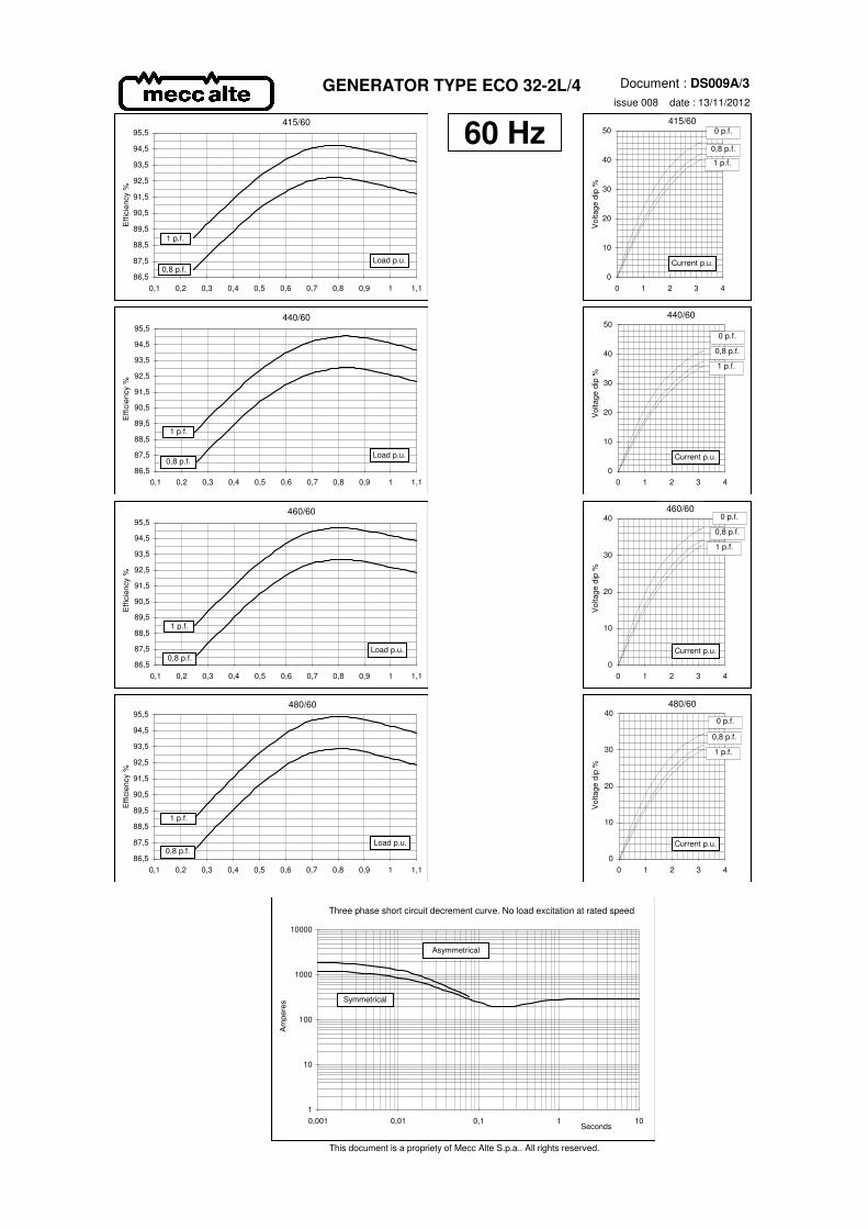
Document : DS009A/3issue 008 date : 13/11/2012
This document is a propriety of Mecc Alte S.p.a.. All rights reserved.
GENERATOR TYPE ECO 32-2L/4
60 Hz
86,5
87,5
88,5
89,5
90,5
91,5
92,5
93,5
94,5
95,5
0,1 0,2 0,3 0,4 0,5 0,6 0,7 0,8 0,9 1 1,1
Effi
cien
cy %
Load p.u.
415/60
0,8 p.f.
1 p.f.
86,5
87,5
88,5
89,5
90,5
91,5
92,5
93,5
94,5
95,5
0,1 0,2 0,3 0,4 0,5 0,6 0,7 0,8 0,9 1 1,1
Effi
cien
cy %
Load p.u.
1 p.f.
0,8 p.f.
440/60
86,5
87,5
88,5
89,5
90,5
91,5
92,5
93,5
94,5
95,5
0,1 0,2 0,3 0,4 0,5 0,6 0,7 0,8 0,9 1 1,1
Effi
cien
cy %
Load p.u.
1 p.f.
0,8 p.f.
86,5
87,5
88,5
89,5
90,5
91,5
92,5
93,5
94,5
95,5
0,1 0,2 0,3 0,4 0,5 0,6 0,7 0,8 0,9 1 1,1
Effi
cien
cy %
Load p.u.
1 p.f.
0,8 p.f.
0
10
20
30
40
50
0 1 2 3 4
Vol
tage
dip
%
415/60
Current p.u.
0,8 p.f.
1 p.f.
0 p.f.
0
10
20
30
40
50
0 1 2 3 4
Vol
tage
dip
%
Current p.u.
440/60
0 p.f.
0,8 p.f.
1 p.f.
0
10
20
30
40
0 1 2 3 4
Vol
tage
dip
%
Current p.u.
0 p.f.
0,8 p.f.
1 p.f.
460/60
480/60
460/60
0
10
20
30
40
0 1 2 3 4
Vol
tage
dip
%
Current p.u.
0 p.f.
0,8 p.f.
1 p.f.
1
10
100
1000
10000
0,001 0,01 0,1 1 10
Am
pere
s
Three phase short circuit decrement curve. No load excitation at rated speed
Seconds
Asymmetrical
Symmetrical
480/60

