mechanical behavior of multi-spherical sliding bearings
TRANSCRIPT
ISSN 1520-295X
Mechanical Behavior of Multi-Spherical Sliding Bearings
by Daniel M. Fenz and Michael C. Constantinou
Technical Report MCEER-08-0007
March 6, 2008
This research was conducted at the University at Buffalo, The State University of New York and was supported primarily by
the Earthquake Engineering Research Centers Program of the National Science Foundation under award number EEC 9701471.

NOTICEThis report was prepared by the University at Buffalo, The State University of New York as a result of research sponsored by MCEER through a grant from the Earthquake Engineering Research Centers Program of the National Sci-ence Foundation under NSF award number EEC-9701471 and other sponsors. Neither MCEER, associates of MCEER, its sponsors, the University at Buffalo, The State University of New York, nor any person acting on their behalf:
a. makes any warranty, express or implied, with respect to the use of any information, apparatus, method, or process disclosed in this report or that such use may not infringe upon privately owned rights; or
b. assumes any liabilities of whatsoever kind with respect to the use of, or the damage resulting from the use of, any information, apparatus, method, or process disclosed in this report.
Any opinions, findings, and conclusions or recommendations expressed in this publication are those of the author(s) and do not necessarily reflect the views of MCEER, the National Science Foundation, or other sponsors.
Mechanical Behavior of Multi-Spherical Sliding Bearings
by
Daniel M. Fenz1 and Michael C. Constantinou2
Publication Date: March 6, 2008 Submittal Date: January 16, 2008
Technical Report MCEER-08-0007
Task Number 10.2.2
NSF Master Contract Number EEC 9701471
1 Ph.D. Candidate, Department of Civil, Structural and Environmental Engineering, University at Buffalo, The State University of New York
2 Professor, Department of Civil, Structural and Environmental Engineering, Univer-sity at Buffalo, The State University of New York
MCEERUniversity at Buffalo, The State University of New YorkRed Jacket Quadrangle, Buffalo, NY 14261Phone: (716) 645-3391; Fax (716) 645-3399E-mail: [email protected]; WWW Site: http://mceer.buffalo.edu

NTIS DISCLAIMER
! This document has been reproduced from the best copy furnished by the sponsoring agency.

iii
Preface
The Multidisciplinary Center for Earthquake Engineering Research (MCEER) is a national center of excellence in advanced technology applications that is dedicated to the reduction of earthquake losses nationwide. Headquartered at the University at Buffalo, State University of New York, the Center was originally established by the National Science Foundation in 1986, as the National Center for Earthquake Engineering Research (NCEER).
Comprising a consortium of researchers from numerous disciplines and institutions throughout the United States, the Center’s mission is to reduce earthquake losses through research and the application of advanced technologies that improve engineering, pre-earthquake planning and post-earthquake recovery strategies. Toward this end, the Cen-ter coordinates a nationwide program of multidisciplinary team research, education and outreach activities.
MCEER’s research is conducted under the sponsorship of two major federal agencies: the National Science Foundation (NSF) and the Federal Highway Administration (FHWA), and the State of New York. Signifi cant support is derived from the Federal Emergency Management Agency (FEMA), other state governments, academic institutions, foreign governments and private industry.
MCEER’s NSF-sponsored research objectives are twofold: to increase resilience by devel-oping seismic evaluation and rehabilitation strategies for the post-disaster facilities and systems (hospitals, electrical and water lifelines, and bridges and highways) that society expects to be operational following an earthquake; and to further enhance resilience by developing improved emergency management capabilities to ensure an effective response and recovery following the earthquake (see the fi gure below).
-
Infrastructures that Must be Available /Operational following an Earthquake
Intelligent Responseand Recovery
Hospitals
Water, GasPipelines
Electric PowerNetwork
Bridges andHighways
MoreEarthquake
Resilient UrbanInfrastructureSystem
Cost-EffectiveRetrofitStrategies
Earthquake Resilient CommunitiesThrough Applications of Advanced Technologies

iv
A cross-program activity focuses on the establishment of an effective experimental and analytical network to facilitate the exchange of information between researchers located in various institutions across the country. These are complemented by, and integrated with, other MCEER activities in education, outreach, technology transfer, and industry partnerships.
This report describes the principles of operation and the development of cyclic force-displacement relationships for three variations of multi-spherical sliding bearings: the double FP bearing, the triple FP bearing, and the modifi ed single FP bearing. The force-displacement relationships of de-vices with increasingly complex behavior were determined by extending the fundamental principles of operation that apply to sliding on a single concave surface. It was shown that each device is capable of exhibiting displacement-dependent adaptive behavior, i.e., desirable changes in stiffness and damping over the course of motion. These changes are determined by the relative values of each surface’s coeffi cient of friction, effective radius of curvature, and displacement capacity. Since all are predefi ned design parameters (aside from the inherent uncertainty and variability in the coeffi cient of friction), their behavior is completely controllable by the engineer. In addition, it was shown that in cases where multiple surfaces are of equal friction, the complexity of behavior exhibited by these devices is reduced. This is important because bearings of smaller plan dimension can still use familiar and proven methods of analysis and design, resulting in signifi cant cost savings. A future report will detail the development, experimental verifi cation and application of tools for dynamic analysis of structures isolated with these bearings.
v
ABSTRACT
The principles of operation and mechanical behavior of three novel spherical sliding isolation bearings are developed in this report. Their internal construction consists of multiple concave surfaces and behavior is dictated by the different combinations of surfaces upon which sliding can occur over the course of motion. As the surfaces upon which sliding is occurring change, the stiffness and effective friction change accordingly. These bearings are completely passive devices, yet exhibit adaptive stiffness and adaptive damping. That is, the stiffness and damping change to predictable values at calculable and controllable displacement amplitudes. The primary benefit of adaptive behavior is that a given isolation system can be separately optimized for multiple performance objectives and/or multiple levels of ground shaking. With the devices presented here, this is accomplished using technology that is inherently no more complex than what is currently used by the civil engineering profession. In this report, the force-displacement relationships are derived based on first principles and by extending basic theories that apply to sliding upon a single concave surface. The theoretical behavior is validated experimentally through extensive component testing of the various devices. It is shown that the forces and displacements at which transitions in stiffness occur are predictable and therefore controllable in design.


vii
ACKNOWLEDGEMENTS
Financial support for the work presented in this report has been provided by the Multidisciplinary Center for Earthquake Engineering Research (Thrust Area 2: Seismic Design and Retrofit of Acute Care Facilities) and Earthquake Protection Systems, Inc. This support is gratefully acknowledged.


ix
TABLE OF CONTENTS
SECTION TITLE PAGE 1 INTRODUCTION 1 2 DESCRIPTION AND PRINCIPLES OF OPERATION 11 2.1 Introduction 11 2.2 Construction of the Double FP Bearing 11 2.3 Construction of the Triple FP Bearing 14 2.4 Construction of the Modified Single FP Bearing 16 2.5 Principles of Operation 17 2.5.1 Mechanics of Sliding on a Single Concave Surface 17 2.5.2 Rigorous Derivation of the Effective Radius of a
Spherical Sliding Surface 20
2.5.3 Effect of Contacting the Displacement Restrainer 25 2.5.4 Actual Displacement Capacity of a Concave Surface 26 2.5.5 Effect of Concave Plate Rotations 29 2.5.6 Extension to Multiple Surfaces: Sliding Regimes and
their Sequencing 35
3 FORMULATION OF THE FORCE-DISPLACEMENT
RELATIONSHIP FOR DOUBLE FP BEARINGS 37
3.1 Introduction 37 3.2 Sliding Regime I 37 3.3 Sliding Regime II 39 3.4 Sliding Regime III 42 3.5 Additional Comments 46 3.5.1 Behavior for Equal Friction Configurations 46 3.5.2 Applicability of Series Models 48 3.5.3 Slider Offset in Displacement-Controlled Cyclic Motion 48 3.5.4 Effect of Concave Plate Rotations 50 3.5.5 Modeling for Dynamic Analysis 57 3.5.6 Values of Property Modification Factors 58 3.5.7 P − Δ Moment Transfer 59 4 FORMULATION OF THE FORCE-DISPLACEMENT
RELATIONSHIP FOR TRIPLE FP BEARINGS 61
4.1 Introduction 61 4.2 Sliding Regime I 62 4.3 Sliding Regime II 65 4.4 Sliding Regime III 68 4.5 Sliding Regime IV 70 4.6 Sliding Regime V 73 4.7 Additional Comments 77
x
TABLE OF CONTENTS (CONT’D)
SECTION TITLE PAGE 4.7.1 Behavior for Equal Friction Configurations 77 4.7.2 Applicability of Series Models 78 4.7.3 Actual Forces at which the Slider Contacts the
Displacement Restrainer on Surfaces 2 and 3 80
4.7.4 Slider Offsets in Displacement-Controlled Tests 80 4.7.5 Effect of Concave Plate Rotations 81 4.8 Behavior of the Modified Single FP Bearing 85 5 EXPERIMENTAL VALIDATION OF MECHANICAL
BEHAVIOR 91
5.1 Introduction 91 5.2 Description of Test Specimens 91 5.3 Description of Test Apparatus and Instrumentation 98 5.4 Testing Program and Procedures 100 5.5 Experimental Results for the Double FP Bearing 102 5.5.1 Data Analysis and Construction of Analytical Force-
Displacement Loops 102
5.5.2 Behavior Prior to Contacting the Displacement Restrainer (Sliding Regimes I and II)
102
5.5.3 Behavior After Contacting the Displacement Restrainer (Sliding Regime III)
111
5.6 Experimental Results for the Triple FP Bearing 117 5.6.1 Quantitative Comparison of Experimental and Analytical
Results 117
5.6.2 Experimental Verification of Principles of Operation 122 5.6.3 Comments on Tests at High Speed 125 5.6.4 Testing of a Simpler Configuration 127 5.7 Experimental Results for the Modified Single FP Bearing 129 6 CONCLUSION 133 7 REFERENCES 135
xi
LIST OF ILLUSTRATIONS
FIGURE TITLE PAGE 1-1 Displacement Control and Uplift Restraint Device Shown
(a) Fully Extended and (b) in its Undeformed Configuration Within an Elastomeric Bearing (after Kelly et al., 1987)
3
1-2 Horizontal Force-Displacement Relationship for an Elastomeric Bearing with the Displacement Control and Uplift Restraint Device (a) Prior to Engaging and (b) After Engaging (reproduced from Kelly et al., 1987)
3
1-3 Multi-phase Layered Annular Elastomeric Springs Used as Backup Devices in Japan (after Sumitomo, 1990)
4
1-4 Examples of Use of Elastomeric Springs as Backup Devices to Lead-Rubber Bearings in the Asano and Excel Minami-Koshigaya Buildings in Japan (reproduced from Sumitomo, 1990)
5
1-5 Horizontal Force-Displacement Data for the Devices Used in the Asano and Excel Minami-Koshigaya Buildings in Japan (Reproduced from Sumitomo, 1990)
6
1-6 Displacement Restrainer Ring of a FP Bearing 61-7 Engagement of Displacement Restrainer Ring During Shake
Table Testing of FP Bearing at UC Berkeley (reproduced from Zayas et al., 1987)
7
1-8 Cross Section of Composite Isolator as Presented in the Patent of Tarics
9
2-1 1870 Patent of Jules Touaillon 122-2 Cutaway View of the Double FP Bearing 132-3 Cross Section of the Double FP Bearing with Surfaces of (a)
Equal Displacement Capacity and (b) Different Displacement Capacity
13
2-4 Cutaway View of the Triple FP Bearing 152-5 Cross Section of the Triple FP Bearing 152-6 Cutaway View of the Modified Single FP Bearing 172-7 Cross Section of the Modified Single FP Bearing 172-8 Free Body Diagram the Slider of the Single FP Bearing in
the Deformed Configuration 18
2-9 Hysteretic Behavior of the Traditional Single FP Bearing 202-10 Illustration of Pendulum Motion of the Supported Structure
(Pivot Point Within Boundary of Spherical Sliding Surface) 21
2-11 Geometry of the Displaced Bearing (Pivot Point Within Boundary of Spherical Sliding Surface)
22
2-12 Illustration of Pendulum Motion of the Supported Structure (Pivot Point Outside Boundary of Spherical Sliding Surface)
23

xii
LIST OF ILLUSTRATIONS (CONT’D)
FIGURE TITLE PAGE 2-13 Geometry of the Displaced Bearing (Pivot Point Outside
Boundary of Spherical Sliding Surface) 24
2-14 Force-Displacement Relationship of a Single FP Bearing Whose Slider has Contacted the Displacement Restrainer Assuming (a) Rigid Elastic Behavior and (b) Non-Rigid Plastic Behavior
27
2-15 Illustration of the Actual Displacement Capacity ( 'd ) of the Double FP in Relation to the Nominal Displacement Capacity ( d )
28
2-16 Illustration of the Actual Displacement Capacity ( 'd ) of the Single FP in Relation to the Nominal Displacement Capacity ( d )
30
2-17 Single FP Bearing Used for the Benecia-Martinez Bridge 312-18 Free Body Diagram of the Slider in a Single FP Bearing
with Concave Plate Having Rotation τ 32
2-19 Shift in the Force-Displacement Loop of Single FP Bearings Caused by Concave Plate Rotation
34
2-20 Effect of Different Types of Concave Plate Rotation on the Hysteretic Behavior of Single FP Bearings
34
3-1 Displaced Shape (a) and Free Body Diagrams (b) of the
Double FP Bearing During Sliding Regime I 38
3-2 Force-Displacement Relationship for Sliding Regime I 393-3 Displaced Shape (a) and Free Body Diagrams (b) of the
Double FP Bearing During Sliding Regime II 40
3-4 Force-Displacement Relationship for Sliding Regime II Shown in Comparison to Sliding Regime I
42
3-5 Displaced Shape (a) and Free Body Diagrams (b) of the Double FP Bearing During Sliding Regime III
44
3-6 Force-Displacement Relationship (a) for Sliding Regime III(a) Shown in Comparison to Sliding Regimes I-II and (b) for Sliding Regime III(b) Shown in Comparison to Sliding Regimes I-III(a)
45
3-7 Exact Analytical Model of the Double FP Bearing as Two Single FP Elements in Series
48
3-8 Total (a) and Decomposed (b) and (c) Hysteresis Loops for a Configuration of Double FP Bearing Having Unequal Radii of Curvature and Unequal Coefficients of Friction
49
3-9 Total (a) and Decomposed (b) and (c) Hysteresis Loops for example bearing with 1 0.01τ = + and 2 0.01τ = +
52

xiii
LIST OF ILLUSTRATIONS (CONT’D)
FIGURE TITLE PAGE 3-10 Total (a) and Decomposed (b) and (c) Hysteresis Loops for
Example Bearing with 1 0.02τ = + and 2 0.01τ = + 54
3-11 Total (a) and Decomposed (b) and (c) Hysteresis Loops for Example Bearing with 1 0.01τ = + and 2 -0.01τ =
55
3-12 Total (a) and Decomposed (b) and (c) Hysteresis Loops for Example Bearing with 1 0.01τ = + and 2 0τ = and Slider that Contacts the Displacement Restrainer
57
4-1 Displaced Shape (a) and Free Body Diagrams (b) of the
Triple FP Bearing During Sliding Regime I 63
4-2 Force-Displacement Relationship During Sliding Regime I 644-3 Displaced Shape (a) and Free Body Diagrams (b) of the
Triple FP Bearing During Sliding Regime II 66
4-4 Force-Displacement Relationship During Sliding Regime II Shown in Relation to Sliding Regime I
67
4-5 Displaced Shape (a) and Free Body Diagrams (b) of the Triple FP Bearing During Sliding Regime III
69
4-6 Force-Displacement Relationship During Sliding Regime III Shown in Relation to Sliding Regimes I-and II
70
4-7 Displaced Shape (a) and Free Body Diagrams (b) of the Triple FP Bearing During Sliding Regime IV
72
4-8 Force-Displacement Relationship During Sliding Regime IV Shown in Relation to Sliding Regimes I-III
73
4-9 Displaced Shape (a) and Free Body Diagrams (b) of the Triple FP Bearing During Sliding Regime V
74
4-10 Force-Displacement Relationship During Sliding Regime V Shown in Relation to Sliding Regimes I-IV
77
4-11 Collapse of Adaptive Triple FP Bearing’s Behavior to Simpler Cases in Configurations of Equal Friction
79
4-12 Stable Equilibrium Position of Triple FP Bearing Having Concave Plate Rotations of 1+τ and 4+τ
81
4-13 Force-Displacement Relationship of the Modified Single FP Bearing (a) for Sliding Regime I, (b) for Sliding Regime II and (c) for Sliding Regime III
86
4-14 Displaced Shape (a) and Free Body Diagrams (b) of the Modified Single FP Bearing During Sliding Regime II
87
5-1 Dimensions of Double FP Specimens Tested with (a) Equal
Radii of Curvature and (b) Different Radii of Curvature and (c) Photograph of Specimen
92
xiv
LIST OF ILLUSTRATIONS (CONT’D)
FIGURE TITLE PAGE 5-2 Dimensions (a) and Photograph (b) of Triple FP Bearing
Tested 93
5-3 Dimensions (a) and Photograph (b) of Modified Single FP Bearing Tested
94
5-4 Sketch of Urethane Ring Inserted to Reduce the Displacement Capacity of the Concave Plate
95
5-5 Summary of the Various Configurations of Multi-Spherical Sliding Bearings Tested
96
5-6 Apparatus Used for Experimental Testing 995-7 Dimensioned Drawing of Test Apparatus – Stability Bracing
not Shown (Reproduced from Kasalanati and Constantinou, 1999)
99
5-8 Illustration of the Range in the Coefficient of Friction for Low Speed and High Speed Testing
100
5-9 Comparison of Analytical and Experimental Loops for the Double FP Bearing in Configuration 1 (Surfaces Have Equal Radii and Equal Friction)
103
5-10 Comparison of Analytical and Experimental Loops for the Double FP Bearing in Configuration 2 (Surfaces Have Unequal Radii and Equal Friction)
104
5-11 Comparison of Analytical and Experimental Loops for the Double FP Bearing in Configuration 3 (Surfaces Have Equal Radii and Unequal Friction)
104
5-12 Comparison of Analytical and Experimental Loops for the Double FP Bearing in Configuration 4 (Surfaces Have Unequal Radii and Unequal Friction)
105
5-13 Decomposed Hysteresis Loops for the Double FP Bearing in Configuration 3 (Equal Radii and Unequal Friction)
106
5-14 Decomposed Hysteresis Loops for the Double FP Bearing in Configuration 4 (Surfaces Have Unequal Radii and Unequal Friction)
106
5-15 Histories of Displacement for the Double FP Bearing in Configuration 1 (Surfaces Have Equal Radii and Equal Friction)
107
5-16 Histories of Displacement for the Double FP Bearing in Configuration 2 (Surfaces Have Unequal Radii and Equal Friction)
108
5-17 Histories of Displacement for the Double FP Bearing in Configuration 3 (Surfaces Have Equal Radii and Unequal Friction)
109

xv
LIST OF ILLUSTRATIONS (CONT’D)
FIGURE TITLE PAGE 5-18 Histories of Displacement for the Double FP Bearing in
Configuration 4 (Surfaces Have Unequal Radii and Unequal Friction)
110
5-19 Double FP Bearing Displaced During Cyclic Testing (Zip Ties Denote Location of String Potentiometer Attachment)
111
5-20 Double FP Bearing Having Surfaces of Different Displacement Capacity Displaced During Cyclic Testing (Installation Typical of Configurations 5 and 7)
112
5-21 Comparison of Analytical and Experimental Loops for the Double FP Bearing in Configuration 5
113
5-22 Comparison of Analytical and Experimental Loops for the Double FP Bearing in Configuration 6
114
5-23 Comparison of Analytical and Experimental Loops for the Double FP Bearing in Configuration 7
114
5-24 Decomposed Hysteresis Loops for the Double FP Bearing in Configuration 7, Sliding Regime III(b)
115
5-25 Histories of Velocity for the Double FP Bearing in Configuration 7 During the 95 mm and 115 mm Amplitude Tests
116
5-26 Comparison of Experimental and Analytical Results for Force-Displacement Relationship of Triple FP Specimen in Configuration 1 (Sliding Regimes I – V Shown)
119
5-27 Comparison of Experimental and Analytical Results for Force-Displacement Relationship of Triple FP Specimen in Configuration 2 (Sliding Regimes IV and V Shown)
121
5-28 Comparison of Experimental and Analytical Results for Force-Displacement Relationship of Triple FP Specimen in Configuration 3 (Sliding Regimes IV and V Shown)
121
5-29 Decomposed Experimental Force-Displacement Loops for Triple FP Specimen in Configuration 1
123
5-30 Experimental Histories of Displacement and Velocity for the Triple FP Bearing in Configuration 1 During Cyclic Testing of 140 mm Amplitude
124
5-31 Force-Displacement Loops for Triple FP Specimen in Configuration 1 During Testing at 115 mm Amplitude and Increasing Frequency of Sinusoidal Motion (Peak Velocities are Experimentally Measured Values and Differ Slightly from the Nominal or Target Values)
126
5-32 Force-Displacement Loops for Triple FP Specimen in Simpler Configuration with Upper and Lower Concave Surfaces of Equal Friction
128

xvi
LIST OF ILLUSTRATIONS (CONT’D)
FIGURE TITLE PAGE 5-33 Histories of Displacement for Triple FP Specimen in
Simpler Configuration with Upper and Lower Concave Surfaces of Equal Friction
129
5-34 Comparison of Experimental and Analytical Results for Force-Displacement Relationship of Modified Single FP Specimen in Configuration 1 (Sliding Regimes I, II and III Shown)
130
5-35 Comparison of Experimental and Analytical Results for Force-Displacement Relationship of Modified Single FP Specimen in Configuration 2 (Sliding Regimes I, II and III Shown)
131
5-36 Histories of Displacement and Velocity for the Modified Single FP Bearing in Configuration 1 for the 70 mm Amplitude Test
132
xvii
LIST OF TABLES
TABLE TITLE PAGE 3-1 Summary of Double FP Bearing Behavior (Nomenclature
Refers to Figure 2-3) 47
4-1 Summary of Triple FP Bearing Behavior (Nomenclature
Refers to Figure 2-5) 76
4-2 Summary of Modified Single FP Bearing Behavior (Nomenclature Refers to Figure 2-7)
90
5-1 Summary of Properties of the Various Configurations Tested 975-2 Abridged List of Tests Performed 1015-3 Coefficients of Friction Measured During Experiments used
to Construct Analytical Force-Displacement Loops for Double FP Bearing Configuration 1-4
103
5-4 Coefficients of Friction and Displacement Capacities Measured During Experiments used to Construct Analytical Force-Displacement Loops for Double FP Bearing Configuration 5-7
113
5-5 Comparison of Analytical and Experimental Results for the Double FP Bearing in Configurations 5-7
115
5-6 Coefficients of Friction and Displacement Capacities Measured During Experiments used to Construct Analytical Force-Displacement Loops for Triple FP Bearing Configurations 1-3
118
5-7 Comparison of Analytical and Experimental Results for the Triple FP Bearing
120
5-8 Coefficients of Friction and Displacement Capacities Measured During Experiments used to Construct Analytical Force-Displacement Loops for Modified Single FP Bearing Configurations 1and 2
130
5-9 Comparison of Analytical and Experimental Results for Modified Single FP Bearing Configurations 1 and 2
130

1
SECTION 1 INTRODUCTION
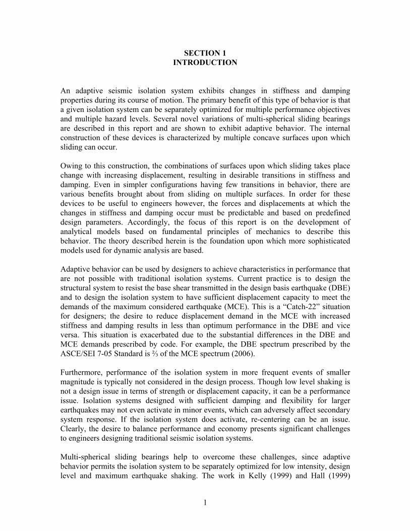
An adaptive seismic isolation system exhibits changes in stiffness and damping properties during its course of motion. The primary benefit of this type of behavior is that a given isolation system can be separately optimized for multiple performance objectives and multiple hazard levels. Several novel variations of multi-spherical sliding bearings are described in this report and are shown to exhibit adaptive behavior. The internal construction of these devices is characterized by multiple concave surfaces upon which sliding can occur. Owing to this construction, the combinations of surfaces upon which sliding takes place change with increasing displacement, resulting in desirable transitions in stiffness and damping. Even in simpler configurations having few transitions in behavior, there are various benefits brought about from sliding on multiple surfaces. In order for these devices to be useful to engineers however, the forces and displacements at which the changes in stiffness and damping occur must be predictable and based on predefined design parameters. Accordingly, the focus of this report is on the development of analytical models based on fundamental principles of mechanics to describe this behavior. The theory described herein is the foundation upon which more sophisticated models used for dynamic analysis are based. Adaptive behavior can be used by designers to achieve characteristics in performance that are not possible with traditional isolation systems. Current practice is to design the structural system to resist the base shear transmitted in the design basis earthquake (DBE) and to design the isolation system to have sufficient displacement capacity to meet the demands of the maximum considered earthquake (MCE). This is a “Catch-22” situation for designers; the desire to reduce displacement demand in the MCE with increased stiffness and damping results in less than optimum performance in the DBE and vice versa. This situation is exacerbated due to the substantial differences in the DBE and MCE demands prescribed by code. For example, the DBE spectrum prescribed by the ASCE/SEI 7-05 Standard is ⅔ of the MCE spectrum (2006). Furthermore, performance of the isolation system in more frequent events of smaller magnitude is typically not considered in the design process. Though low level shaking is not a design issue in terms of strength or displacement capacity, it can be a performance issue. Isolation systems designed with sufficient damping and flexibility for larger earthquakes may not even activate in minor events, which can adversely affect secondary system response. If the isolation system does activate, re-centering can be an issue. Clearly, the desire to balance performance and economy presents significant challenges to engineers designing traditional seismic isolation systems. Multi-spherical sliding bearings help to overcome these challenges, since adaptive behavior permits the isolation system to be separately optimized for low intensity, design level and maximum earthquake shaking. The work in Kelly (1999) and Hall (1999)
2
indicates that that to control displacements in large earthquakes while still maintaining good performance in low-to-moderate earthquakes requires designing an isolation system that is (a) very stiff with low damping at low level shaking, (b) softens with increasing damping in the DBE and (c) stiffens and/or increases damping in the MCE and beyond. When properly configured, multi-spherical sliding bearings exhibit this desirable behavior. The devices that will be presented are distinct from other isolation systems that have displacement-dependent behavior. First and foremost, they are totally passive devices that exhibit adaptive behavior naturally as a result of their internal construction. To date, adaptive (or smart) seismic isolation systems have predominantly consisted of conventional isolation bearings used in conjunction with active or semi-active devices having variable stiffness or damping properties. Several examples of such systems have been reported in the literature: flat sliding systems with variable friction force (i.e., variable normal pressure) (Feng et al., 1993), flat sliders with a control actuator (Riley et al., 1998), flat sliders in conjunction with a variable stiffness restoring force spring (Nagarajaiah and Sahasrabudhe, 2006), spherical sliding bearings with a magnetorheological damper (Lin et al., 2004), elastomeric bearings with variable-orifice fluid dampers (Wongprasert and Symans, 2005) and so on. In general these studies conclude that properly designed active and semi-active hybrid systems can offer improved performance over passive systems in a wider range of earthquakes. However, obstacles related to implementation and serious questions regarding longevity and reliability still persist. In contrast, the multi-spherical sliding bearings presented here are derivatives of the conventional Friction Pendulum (FP) bearing, a mature and established seismic protective technology. These bearings exhibit the desirable behavior of more sophisticated systems, however with technology that is inherently no more complex than what is currently used by the civil engineering profession. Lifetime behavior of both conventional FP bearings and other sliding bridge bearings can be used as evidence supporting the reliability of construction and the longevity of materials used (Constantinou et al., 2007a). Other passive seismic isolation systems have been proposed which offer some type of mechanically derived displacement-dependent stiffness or damping. These bearings roughly fall into two categories: (a) devices with a displacement activated fail-safe mechanism and (b) multi-stage devices. The caveat “mechanically derived” is included to distinguish from elastomeric bearings, which have displacement-dependent stiffness resulting naturally from the strain-dependency of rubber’s material properties. Systems with adaptive behavior owing exclusively to strain-dependent material properties are excluded from this discussion. The devices that belong to the first category are typified by substantial stiffening at large displacements due to engagement of some sort of restraining mechanism. Figure 1-1 shows a displacement-control and uplift-restraint device that can be installed within elastomeric bearings (Kelly et al., 1987). The device consists of two high-strength bolts contained in a sleeve that permits a certain amount of free movement of the bolts. The

3
restrainer becomes taut when the horizontal displacement of the bearing attains a predefined value. Representative hysteresis loops from experimental testing reproduced from Kelly et al. (1987) are shown in figure 1-2. To the best knowledge of the authors these devices have not been employed in actual construction.
FIGURE 1-1 Displacement Control and Uplift Restraint Device Shown (a) Fully Extended and (b) in its Undeformed Configuration Within an Elastomeric Bearing (after Kelly et al., 1987)
(a) (b) FIGURE 1-2 Horizontal Force-Displacement Relationship for an Elastomeric Bearing with the Displacement Control and Uplift Restraint Device (a) Prior to Engaging and (b) After Engaging (reproduced from Kelly et al., 1987)

4
Also in the first category are layered annular elastomeric springs that were developed in Japan (Sumitomo Construction, 1990). These devices, shown in figure 1-3, have been used as a backup system to lead-rubber isolators in at least two buildings. Figure 1-4 shows how they are implemented by Sumitomo Construction in practice. The springs are essentially horizontal stoppers with multi-phase stiffening that act in parallel with the isolation system. They physically engage only when the isolator deforms beyond a certain displacement limit, causing a plunger that is attached to the structure to come into contact with the various steel plates. Sample force-displacement data from the manufacturer demonstrating the multi-stage stiffening is provided in figure 1-5.
FIGURE 1-3 Multi-phase Layered Annular Elastomeric Springs Used as Backup Devices in Japan (after Sumitomo, 1990) In fact, even the original single concave FP bearing can be considered to be in the first category. Single concave FP bearings manufactured by Earthquake Protection Systems Inc. have a displacement restrainer ring on the outer edge of the spherical sliding surface (see figure 1-6). When the slider contacts this ring at large displacement there is substantial stiffening as the resistance mechanism changes to bearing upon the displacement restrainer. The strength however is limited by the capacity of the welds connecting the restrainer ring to the backing plate. This behavior was observed in the original earthquake simulator testing of the FP bearing at UC Berkeley shown in figure 1-7(a) (Zayas et al., 1987) and in later tests at the University of Buffalo as shown in figure 1-7(b) (Constantinou et al., 1993).

5
FIGURE 1-4 Examples of Use of Elastomeric Springs (Denoted “Stoppers” in the Figure) as Backup Devices to Lead-Rubber Bearings in the Asano and Excel Minami-Koshigaya Buildings in Japan (reproduced from Sumitomo, 1990)

6
FIGURE 1-5 Horizontal Force-Displacement Data for the Devices Used in the Asano and Excel Minami-Koshigaya Buildings in Japan (Reproduced from Sumitomo, 1990)
FIGURE 1-6 Displacement Restrainer Ring of a FP Bearing

7
(a)
(b)
FIGURE 1-7 Engagement of Displacement Restrainer Ring During Shake Table Testing of FP Bearing at (a) UC Berkeley (Reproduced from Zayas et al., 1987) and (b) the University of Buffalo (Reproduced from Constantinou et al., 1993) The considerable emphasis on fail-safe devices and backup systems nearly 20 years ago was likely due to initial conservatism associated with the implementation of new technology. The idea is not misguided or obsolete, but rather a prudent approach in limiting excessive isolator displacements. This practice continues today with the use of limited moat space in the isolation system - typically the maximum total displacement per the ASCE/SEI 7-05 Standard or larger. The idea is to prevent failure of the isolation system by not allowing motion beyond the designated maximum displacement capacity of the bearings. In this way, inelastic action occurs in the ductile superstructure (and if not ductile, then strength must be sufficient) and not in the isolation system.

8
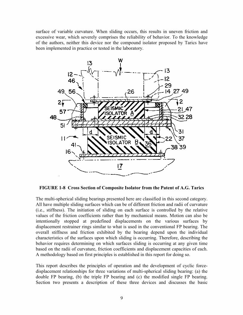
In events of extreme magnitude, when the isolation system impacts the barrier there are substantial forces imparted to the superstructure over a very brief interval of time. Analytically, the problem is exceedingly complex since it is one of dynamic impact involving an assembly of deformable structural elements. There is certainly dynamic amplification of the impact forces, however there may also be mitigating effects due to detuning or high frequency vibration of the structure upon impact. This remains a largely unexplored area in seismic isolation research. Such uncertainty highlights the need to explicitly incorporate sufficient overstrength and/or ductile detailing in the design of the superstructure. To some extent, the structure must be capable of safely sustaining loads past the design level without collapse. Current standards such as ASCE/SEI 7-05 require the superstructure of a seismically isolated structure to be designed for the base shear in the DBE reduced by a response modification factor, IR , of no less than 1.0 and no more than 2.0 (the factor IR is three-eights of the appropriate R factor corresponding to the lateral force resisting system of the superstructure). This provision results in elastic or nearly elastic performance of the superstructure in the design event. Isolation systems that stiffen beyond the DBE or that have fail-safe restraints can subject the superstructure to considerably larger forces than the design level. Without adequate overstrength or ductility, substantial damage or even collapse can occur for events beyond the design level. The extreme example of this scenario would be a brittle masonry building designed with 1IR = and yield strength equal to the design strength of the isolation system. Therefore, nonlinear static analysis of the superstructure is advisable in order to verify its performance and safety for the maximum expected isolation system shear. Displacement-dependent isolation systems classified in the second category can be thought of as more sophisticated than those in the first since they use multi-stage behavior to control response rather than simply as a means of preventing failure. The first system of this type was a composite isolator proposed by A.G. Tarics (1995) and reported in Imbimbo and Kelly (1997). As shown in figure 1-8, the composite isolator consists of two elastomeric bearings stacked on top of each other with one much stiffer than the other. In this arrangement, the softer bearing (isolator A of figure 1-8) will sustain most of the displacement up to a certain force level at which point it engages the stiffer bearing (isolator B of figure 1-8). Beyond this point, the softer bearing is set at this fixed displacement ( d from figure 1-8) and the stiffer one deforms to sustain the rest of the displacement. In this configuration, the isolation system readily activates and provides adequate flexibility for lower levels of input yet has sufficient stiffness to limit displacements in the maximum event. This is an example of adaptive bearings being able to satisfy different performance objectives for different levels of hazard. A sliding bearing that has a single sliding surface with variable curvature has also been proposed (Pranesh and Sinha, 2000). This is essentially a variable stiffness device. Though it is conceptually appealing and has been shown to be effective in numerical studies, there are issues regarding practical implementation of this device (no experimental results have been reported in the literature). A complex and dynamic pressure distribution exists at the sliding interface between the articulated slider and the
9
surface of variable curvature. When sliding occurs, this results in uneven friction and excessive wear, which severely comprises the reliability of behavior. To the knowledge of the authors, neither this device nor the compound isolator proposed by Tarics have been implemented in practice or tested in the laboratory.
FIGURE 1-8 Cross Section of Composite Isolator from the Patent of A.G. Tarics The multi-spherical sliding bearings presented here are classified in this second category. All have multiple sliding surfaces which can be of different friction and radii of curvature (i.e., stiffness). The initiation of sliding on each surface is controlled by the relative values of the friction coefficients rather than by mechanical means. Motion can also be intentionally stopped at predefined displacements on the various surfaces by displacement restrainer rings similar to what is used in the conventional FP bearing. The overall stiffness and friction exhibited by the bearing depend upon the individual characteristics of the surfaces upon which sliding is occurring. Therefore, describing the behavior requires determining on which surfaces sliding is occurring at any given time based on the radii of curvature, friction coefficients and displacement capacities of each. A methodology based on first principles is established in this report for doing so. This report describes the principles of operation and the development of cyclic force-displacement relationships for three variations of multi-spherical sliding bearing: (a) the double FP bearing, (b) the triple FP bearing and (c) the modified single FP bearing. Section two presents a description of these three devices and discusses the basic
10
principles of operation that are universally applicable. Sections three and four show the development of the force-displacement relationships for each variation of bearing. Section five describes the testing program undertaken to experimentally validate the proposed force-displacement behavior. Multiple configurations of each bearing were tested in order to more completely verify the analytical models. The results demonstrate that there are indeed changes in stiffness and damping over the course of motion and that these changes can be predicted using the analytical models that were developed. A future report will detail the development, experimental verification and application of tools for dynamic analysis of structures isolated with these bearings. The behavior of these devices is much more complex than other isolators that are currently used. Therefore, thorough understanding of fundamental mechanical behavior is an essential first step before developing more sophisticated models used for dynamic analysis.
11
SECTION 2 DESCRIPTION AND PRINCIPLES OF OPERATION
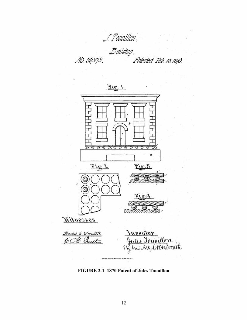
2.1 Introduction This section provides a description of the basic construction of several variations of multi-spherical sliding bearings. Principles of operation that apply to all variations of these bearings are also discussed. These are the basic physical principles and assumptions upon which the analytical models are founded. In many cases, they are simply a logical extension of single FP bearing behavior. Although the force-displacement behavior of these devices can be complex, it ultimately follows from application of these few fundamental concepts. Essentially, the construction of these devices consists of various arrangements of concave plates and internal sliders. The concept is not new, in fact, the first documented isolation system for buildings was a double concave rolling ball bearing that was patented in the US in 1870 (Touaillon, 1870). This system was invented by Jules Touaillon and is shown in figure 2-1. What has changed in the nearly 140 years since the patent was issued is not an improvement on the basic concept of seismic isolation (which arguably was known of long before 1870), but the capability to execute it using technology that exhibits predictable and reliable behavior over the lifetime of the structure. 2.2 Construction of the Double FP Bearing The double FP bearing consists of two facing concave stainless-steel surfaces separated by an articulated slider as shown in figures 2-2 and 2-3. The lower and upper concave plates have radii of curvature 1R and 2R , respectively, which may be unequal. The coefficients of friction for sliding upon these surfaces are 1μ and 2μ , respectively, which may also be unequal. The nominal displacement capacities of the slider upon the lower and upper surfaces are 1d and 2d , respectively, resulting in a total nominal displacement capacity for the entire bearing (top plate relative to bottom plate) of 1 2d d+ . Due to the effects of slider height and slider rotation, the actual displacement capacities are slightly different that the nominal values. The formulation developed in this report also permits that 1 2d d≠ as shown in figure 2-3(b), allowing for a more general description of behavior. The articulation of the slider is necessary for proper distribution of pressure at the sliding interface and to accommodate different movement along the top and bottom sliding surfaces. Previous implementation of a similar type of double concave bearing reported by Hyakuda et al. (2001) concerned devices with internal sliders that lack articulation. Without articulation however, the slider is subject to uneven wear and may have large variation in its frictional properties over time.
12
FIGURE 2-1 1870 Patent of Jules Touaillon
./~/I?7i/1oJl?
..btliMi(f,AfJ. !J,fJJ1J. fllit/lit'd nJ. /$18/a

13
FIGURE 2-2 Cutaway View of the Double FP Bearing
FIGURE 2-3 Cross Section of the Double FP Bearing with Surfaces of (a) Equal Displacement Capacity and (b) Different Displacement Capacity

14
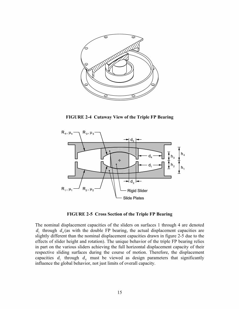
The crosshair in figure 2-3 denotes the location of the point about which the slider rotates, which is termed the pivot point. Due to the ball-in-socket construction, the slider of the double FP bearing is physically constrained to rotate about the center of the spherical joint (a similar ball-in-socket articulation defines the location of the pivot point of single FP bearings). The slider heights 1h and 2h shown in figure 2-3 are the radial distances between the pivot point and the lower and upper concave surfaces respectively. The slider height appears in the equations of equilibrium because the horizontal and vertical forces transmitted by the bearing act at the pivot point. Therefore, it is the effective radii of curvature 1 1 1effR R h= − and 2 2 2effR R h= − that appear in the equations of equilibrium. This definition of the effective radius is investigated in greater detail and proven more rigorously in section 2.5.2. The double FP bearing permits simultaneous sliding on both the upper and lower concave surfaces. Therefore, the total displacement capacity of the bearing is 1 2d d+ , whereas the displacement capacity of a traditional FP bearing of identical plan dimensions would be either 1d or 2d . Accordingly, engineers have recognized that the primary advantage of employing double FP bearings is the cost savings that can be achieved through their more compact size. However, by using concave surfaces of different radii, friction and displacement capacity, adaptive behavior and the attendant benefits in performance can also be achieved. Until now this has remained an unexplored aspect of the device’s behavior. Previous work on a bearing that is identical in concept to the double FP has focused on configurations having concave surfaces of equal friction and equal radii of curvature. This was termed the Multiple FP bearing and has been studied by Tsai et al. (2003a, 2003b, 2005 and 2006). 2.3 Construction of the Triple FP Bearing The triple FP bearing shown in figure 2-4 consists of two facing concave stainless steel surfaces separated by an internal nested slider assembly. Referring to figure 2-5, the outer concave plates have effective radii 1 1 1effR R h= − and 4 4 4effR R h= − , where iR is the radius of curvature of the thi spherical surface and ih is the radial distance between the
thi spherical surface and the pivot point of the articulated slider. The articulated slider assembly consists of two concave slide plates separated by a rigid slider. Though the innermost slider is rigid, the assembly as a whole has the capability to rotate to accommodate differential rotations of the top and bottom slide plates. The surfaces of the slide plates where they mate with the outer concave plates are coated with a non-metallic sliding material. The coefficients of friction of these interfaces are 1μ and 4μ . The inner surfaces of the two slide plates have spherical concave recesses with effective radii
2 2 2effR R h= − and 3 3 3effR R h= − . Both outer surfaces of the rigid slider are also coated with a non-metallic sliding material characterized by coefficients of friction 2μ and 3μ . This permits motion of the rigid slider upon the inner stainless steel surfaces of the slide plates.
15
FIGURE 2-4 Cutaway View of the Triple FP Bearing
FIGURE 2-5 Cross Section of the Triple FP Bearing The nominal displacement capacities of the sliders on surfaces 1 through 4 are denoted
1d through 4d (as with the double FP bearing, the actual displacement capacities are slightly different than the nominal displacement capacities drawn in figure 2-5 due to the effects of slider height and rotation). The unique behavior of the triple FP bearing relies in part on the various sliders achieving the full horizontal displacement capacity of their respective sliding surfaces during the course of motion. Therefore, the displacement capacities 1d through 4d must be viewed as design parameters that significantly influence the global behavior, not just limits of overall capacity.
16
Unlike the single and double FP bearings, in the triple FP bearing, there is no mechanical constraint defining the location of the pivot point. Instead, the pivot point corresponds to the instantaneous center of zero rotational velocity of the slider assembly, which is not a fixed point. The location of the center of zero rotational velocity will actually change as sliding starts and stops on the various surfaces within the bearing. However, since the instantaneous velocities of the top and bottom parts of the slider assembly will always be in opposite directions, the instantaneous center of zero velocity must always lie between them and within the slider assembly. In most cases, the slider height is small in comparison to the radii of curvature and there is little error introduced by assuming the center of zero rotational velocity is fixed at the mid-height of the articulated slider assembly. Similar to the double FP bearing, triple FP bearings permit simultaneous sliding on multiple concave surfaces and therefore can be made much smaller than single FP bearings while still maintaining the same overall displacement capacity. From an economic standpoint, there is negligible difference in the cost of double and triple FP bearings of comparable size. 2.4 Construction of the Modified Single FP Bearing The modified single FP bearing shown in figure 2-6 is a hybrid of the conventional single FP and triple FP bearings. Its construction is similar to the single FP bearing, but with an intermediate slide plate. Referring to figure 2-7, the outer concave plate has effective radius 1 1 1effR R h= − , where 1R is the radius of curvature of the spherical sliding surface and 1h is the radial distance between the sliding surface and the pivot point of the articulated slider. Where it mates with the outer concave plate, the slide plate is coated with a non-metallic sliding material with coefficient of friction 1μ . An articulated slider typical of conventional FP bearings can slide within the spherical recess of the intermediate slide plate. This recess has effective radius 2 2 2effR R h= − where 2R and 2h are defined similar to 1R and 1h . At the sliding interface, the articulated slider is coated with a non-metallic sliding material with coefficient of friction 2μ . The nominal displacement capacities of surfaces 1 and 2 are 1d and 2d respectively. Again, the actual displacement capacities are slightly different. Since most of the sliding occurs on one surface, the plan dimensions of modified single FP bearings will need to be much larger than those of the double or triple FP bearings. For this reason among others, this variation seems less likely to see widespread implementation in practice. However, the modified single FP bearing is studied in this report because it is a simpler adaptation of the triple FP bearing. In fact, it can be thought of as a triple FP bearing cut at mid-height. Certain aspects of behavior that are masked or obscured due the complexity of the triple FP bearing’s behavior can be verified with this simpler device.

17
FIGURE 2-6 Cutaway View of the Modified Single FP Bearing
FIGURE 2-7 Cross Section of the Modified Single FP Bearing 2.5 Principles of Operation 2.5.1 Mechanics of Sliding on a Single Concave Surface Prior to extending the theory to multiple concave surfaces, one must understand the mechanics of sliding on a single concave surface, the forces acting and the underlying assumptions. The behavior of the single FP bearing was described originally by Zayas et al. (1987). The presentation here summarizes that original work and is intended to introduce and explain preliminary concepts relevant to this study.
18
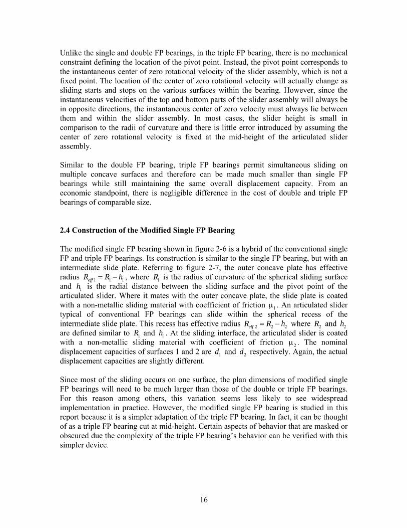
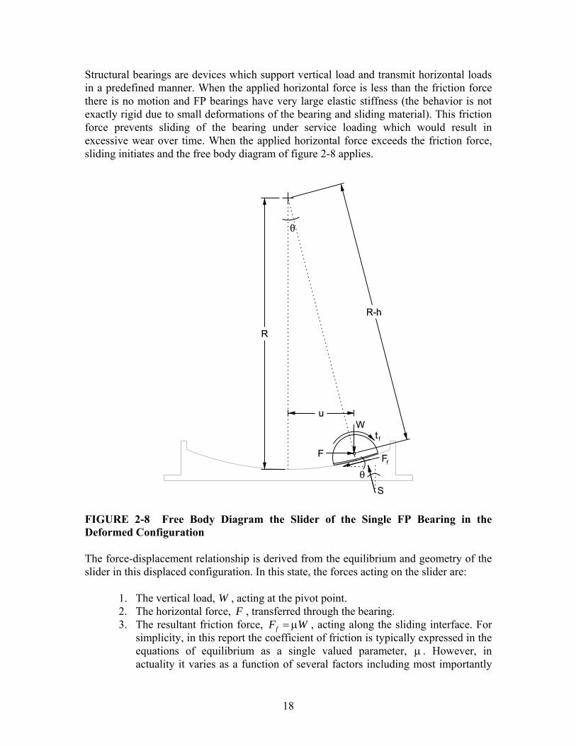
Structural bearings are devices which support vertical load and transmit horizontal loads in a predefined manner. When the applied horizontal force is less than the friction force there is no motion and FP bearings have very large elastic stiffness (the behavior is not exactly rigid due to small deformations of the bearing and sliding material). This friction force prevents sliding of the bearing under service loading which would result in excessive wear over time. When the applied horizontal force exceeds the friction force, sliding initiates and the free body diagram of figure 2-8 applies.
FIGURE 2-8 Free Body Diagram the Slider of the Single FP Bearing in the Deformed Configuration The force-displacement relationship is derived from the equilibrium and geometry of the slider in this displaced configuration. In this state, the forces acting on the slider are:
1. The vertical load, W , acting at the pivot point. 2. The horizontal force, F , transferred through the bearing. 3. The resultant friction force, fF W= μ , acting along the sliding interface. For
simplicity, in this report the coefficient of friction is typically expressed in the equations of equilibrium as a single valued parameter, μ . However, in actuality it varies as a function of several factors including most importantly

19
sliding velocity and pressure (Mokha et al., 1990). For dynamic analysis, the equilibrium equations can be used in their same form, however with ( )uμ , a coefficient of friction that is updated at each time step as a function of the instantaneous sliding velocity. Note that the use of a single valued friction coefficient is a simplification, not a limitation of the formulations presented in this report.
4. The resultant force of normal pressure acting along the sliding interface, S . This must be off center in order to satisfy moment equilibrium. Accordingly, the pressure distribution on the sliding interface is not uniform.
5. Friction tractions along the spherical surface of the articulated slider, ft . Their effect is assumed to be part of the friction force, fF , and therefore they do not appear explicitly in the equations of equilibrium.
Considering equilibrium in the horizontal and vertical directions respectively, equations (2-1a) and (2-1b) are obtained: sin cos 0fF S F− θ − θ = (2-1a) cos sin 0fW S F− θ + θ = (2-1b) From geometry, u , defined as the horizontal displacement of the pivot point of the slider is simply ( )sin sineffu R h R= − θ = θ (2-2) where the effective radius of curvature, effR , is the radial distance from the center of the spherical surface to the pivot point of the articulated slider. Combining equations (2-1a), (2-1b) and (2-2), the force-displacement relationship that governs motion for the single FP bearing is
cos cos
f
eff
FWF uR
= +θ θ
(2-3)
In most applications, the radius of curvature is large compared to the horizontal displacement so that cos 1θ ≈ and the following simplification is made:
feff
WF u FR
= + (2-4)
This simplification introduces less than 5% error provided that the horizontal displacement is less than 30% of the radius of curvature. Equations (2-1) through (2-4) are the equilibrium equations originally presented by Zayas et al. (1987).
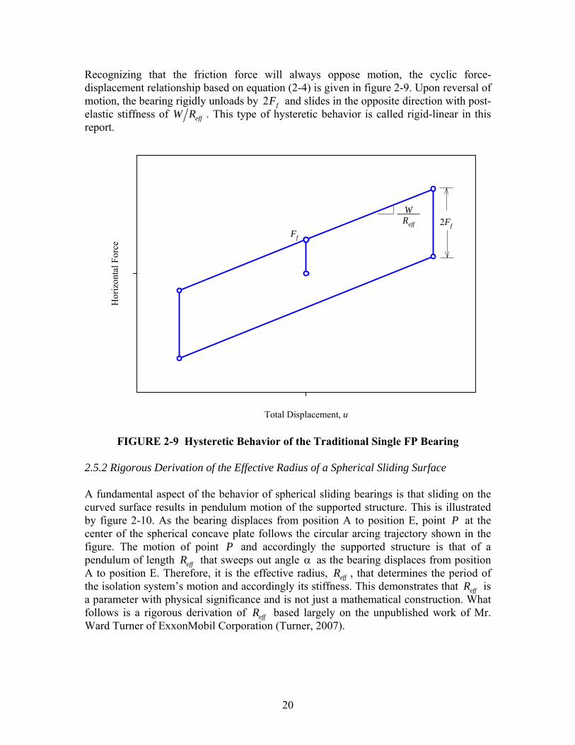
20
Recognizing that the friction force will always oppose motion, the cyclic force-displacement relationship based on equation (2-4) is given in figure 2-9. Upon reversal of motion, the bearing rigidly unloads by 2 fF and slides in the opposite direction with post-elastic stiffness of effW R . This type of hysteretic behavior is called rigid-linear in this report.
Total Displacement, u
Hor
izon
tal F
orce
WReff 2Ff
Ff
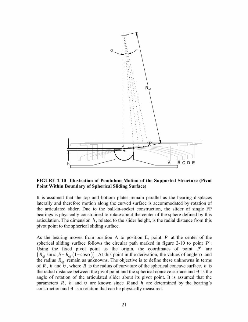
FIGURE 2-9 Hysteretic Behavior of the Traditional Single FP Bearing 2.5.2 Rigorous Derivation of the Effective Radius of a Spherical Sliding Surface A fundamental aspect of the behavior of spherical sliding bearings is that sliding on the curved surface results in pendulum motion of the supported structure. This is illustrated by figure 2-10. As the bearing displaces from position A to position E, point P at the center of the spherical concave plate follows the circular arcing trajectory shown in the figure. The motion of point P and accordingly the supported structure is that of a pendulum of length effR that sweeps out angle α as the bearing displaces from position A to position E. Therefore, it is the effective radius, effR , that determines the period of the isolation system’s motion and accordingly its stiffness. This demonstrates that effR is a parameter with physical significance and is not just a mathematical construction. What follows is a rigorous derivation of effR based largely on the unpublished work of Mr. Ward Turner of ExxonMobil Corporation (Turner, 2007).
21
FIGURE 2-10 Illustration of Pendulum Motion of the Supported Structure (Pivot Point Within Boundary of Spherical Sliding Surface) It is assumed that the top and bottom plates remain parallel as the bearing displaces laterally and therefore motion along the curved surface is accommodated by rotation of the articulated slider. Due to the ball-in-socket construction, the slider of single FP bearings is physically constrained to rotate about the center of the sphere defined by this articulation. The dimension h , related to the slider height, is the radial distance from this pivot point to the spherical sliding surface. As the bearing moves from position A to position E, point P at the center of the spherical sliding surface follows the circular path marked in figure 2-10 to point P′ . Using the fixed pivot point as the origin, the coordinates of point P′ are
( )( )sin , 1 coseff effR h Rα + − α . At this point in the derivation, the values of angle α and the radius effR remain as unknowns. The objective is to define these unknowns in terms of R , h and θ , where R is the radius of curvature of the spherical concave surface, h is the radial distance between the pivot point and the spherical concave surface and θ is the angle of rotation of the articulated slider about its pivot point. It is assumed that the parameters R , h and θ are known since R and h are determined by the bearing’s construction and θ is a rotation that can be physically measured.

22
FIGURE 2-11 Geometry of the Displaced Bearing (Pivot Point Within Boundary of Spherical Sliding Surface) An alternative geometric construction in terms of the known quantities is shown in figure 2-11. Using this description of the displaced bearing’s geometry, the coordinates of point P′ are ( ) ( )( )sin , cosR h R R h− θ − − θ . The two unknown quantities α and effR can be determined by equating the coordinates of point P′ as expressed using the two different geometric constructions. It is simply a system of two equations and two unknowns: ( )sin sineffR R hα = − θ (2-5a)
( ) ( )1 cos coseffh R R R h+ − α = − − θ (2-5b) which are obtained from equating the x and y coordinates respectively. From equation (2-5b), the effective radius can be expressed as
( )( )( )
1 cos1 coseff
R hR
− − θ=
− α (2-6)
When equation (2-6) is substituted into equation (2-5a), it follows that the two angles α and θ are equal and
23
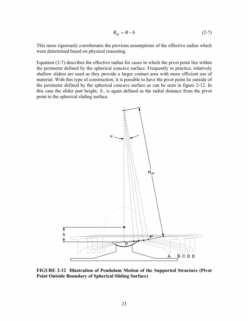
effR R h= − (2-7) This more rigorously corroborates the previous assumptions of the effective radius which were determined based on physical reasoning. Equation (2-7) describes the effective radius for cases in which the pivot point lies within the perimeter defined by the spherical concave surface. Frequently in practice, relatively shallow sliders are used as they provide a larger contact area with more efficient use of material. With this type of construction, it is possible to have the pivot point lie outside of the perimeter defined by the spherical concave surface as can be seen in figure 2-12. In this case the slider part height, h , is again defined as the radial distance from the pivot point to the spherical sliding surface.
FIGURE 2-12 Illustration of Pendulum Motion of the Supported Structure (Pivot Point Outside Boundary of Spherical Sliding Surface)

24
When displaced horizontally, the structure still undergoes pendulum motion as point P at the center of the spherical surface follows the circular arcing trajectory shown in figure 2-12. Using similar geometric constructions as before, the coordinates of point P′ can be expressed as ( )( )sin , 1 coseff effR h Rα − + − α based on figure 2-12 and
( ) ( )( )sin , cosR h R R h+ θ − + θ based on figure 2-13. The slider’s pivot point is used as the origin of the coordinate system in both cases. Equating the x and y coordinates, equations (2-8a) and (2-8b) respectively are obtained: ( )sin sineffR R hα = + θ (2-8a)
( ) ( )1 cos coseffh R R R h− + − α = − + θ (2-8b)
FIGURE 2-13 Geometry of the Displaced Bearing (Pivot Point Outside Boundary of Spherical Sliding Surface) From equation (2-8b), the effective radius can be expressed as
25
( )( )( )
1 cos1 coseff
R hR
+ − θ=
− α (2-9)
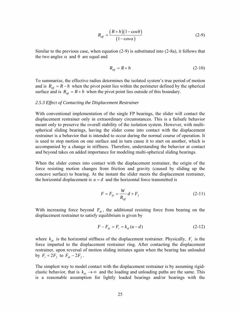
Similar to the previous case, when equation (2-9) is substituted into (2-8a), it follows that the two angles α and θ are equal and effR R h= + (2-10) To summarize, the effective radius determines the isolated system’s true period of motion and is effR R h= − when the pivot point lies within the perimeter defined by the spherical surface and is effR R h= + when the pivot point lies outside of this boundary. 2.5.3 Effect of Contacting the Displacement Restrainer With conventional implementation of the single FP bearings, the slider will contact the displacement restrainer only in extraordinary circumstances. This is a failsafe behavior meant only to preserve the overall stability of the isolation system. However, with multi-spherical sliding bearings, having the slider come into contact with the displacement restrainer is a behavior that is intended to occur during the normal course of operation. It is used to stop motion on one surface and in turn cause it to start on another, which is accompanied by a change in stiffness. Therefore, understanding the behavior at contact and beyond takes on added importance for modeling multi-spherical sliding bearings. When the slider comes into contact with the displacement restrainer, the origin of the force resisting motion changes from friction and gravity (caused by sliding up the concave surface) to bearing. At the instant the slider meets the displacement restrainer, the horizontal displacement is u d= and the horizontal force transmitted is
dr feff
WF F d FR
= = + (2-11)
With increasing force beyond drF , the additional resisting force from bearing on the displacement restrainer to satisfy equilibrium is given by ( )dr r drF F F k u d− = = − (2-12) where drk is the horizontal stiffness of the displacement restrainer. Physically, rF is the force imparted to the displacement restrainer ring. After contacting the displacement restrainer, upon reversal of motion sliding initiates again when the bearing has unloaded by 2r fF F+ to 2dr fF F− . The simplest way to model contact with the displacement restrainer is by assuming rigid-elastic behavior, that is drk → ∞ and the loading and unloading paths are the same. This is a reasonable assumption for lightly loaded bearings and/or bearings with the
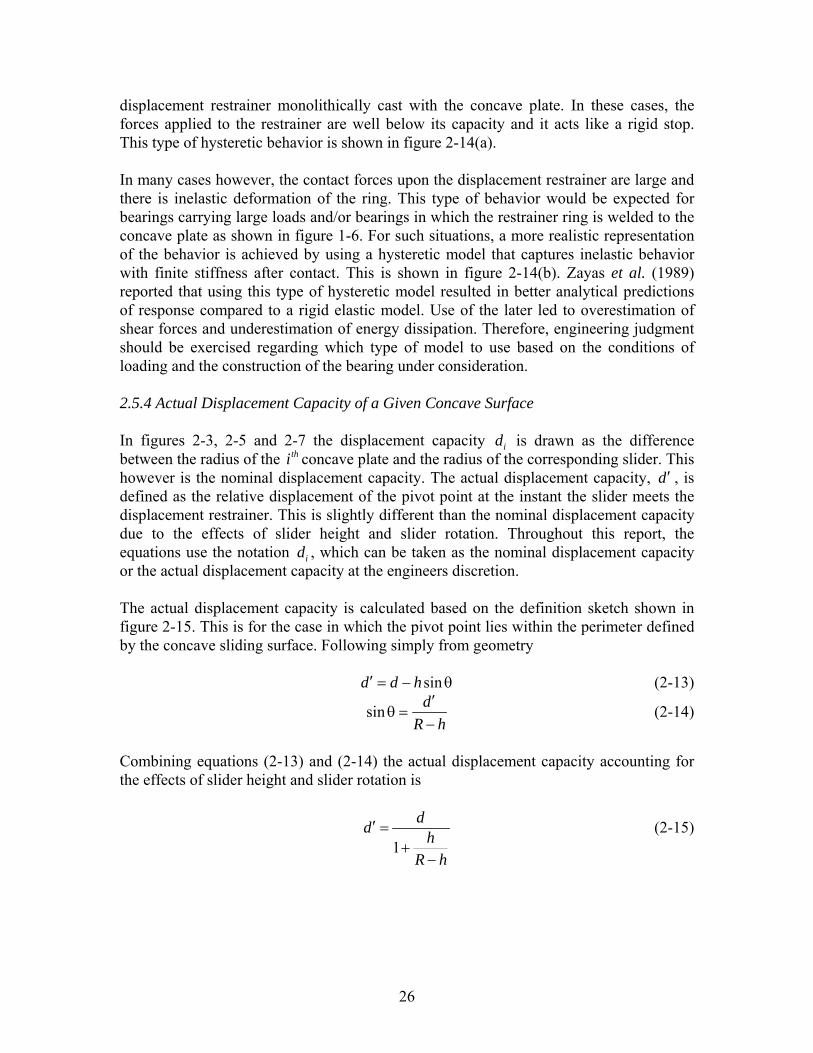
26
displacement restrainer monolithically cast with the concave plate. In these cases, the forces applied to the restrainer are well below its capacity and it acts like a rigid stop. This type of hysteretic behavior is shown in figure 2-14(a). In many cases however, the contact forces upon the displacement restrainer are large and there is inelastic deformation of the ring. This type of behavior would be expected for bearings carrying large loads and/or bearings in which the restrainer ring is welded to the concave plate as shown in figure 1-6. For such situations, a more realistic representation of the behavior is achieved by using a hysteretic model that captures inelastic behavior with finite stiffness after contact. This is shown in figure 2-14(b). Zayas et al. (1989) reported that using this type of hysteretic model resulted in better analytical predictions of response compared to a rigid elastic model. Use of the later led to overestimation of shear forces and underestimation of energy dissipation. Therefore, engineering judgment should be exercised regarding which type of model to use based on the conditions of loading and the construction of the bearing under consideration. 2.5.4 Actual Displacement Capacity of a Given Concave Surface In figures 2-3, 2-5 and 2-7 the displacement capacity id is drawn as the difference between the radius of the thi concave plate and the radius of the corresponding slider. This however is the nominal displacement capacity. The actual displacement capacity, d ′ , is defined as the relative displacement of the pivot point at the instant the slider meets the displacement restrainer. This is slightly different than the nominal displacement capacity due to the effects of slider height and slider rotation. Throughout this report, the equations use the notation id , which can be taken as the nominal displacement capacity or the actual displacement capacity at the engineers discretion. The actual displacement capacity is calculated based on the definition sketch shown in figure 2-15. This is for the case in which the pivot point lies within the perimeter defined by the concave sliding surface. Following simply from geometry sind d h′ = − θ (2-13)
sin dR h
′θ =
− (2-14)
Combining equations (2-13) and (2-14) the actual displacement capacity accounting for the effects of slider height and slider rotation is
1
dd hR h
′ =+
−
(2-15)
27
Total Displacement, u
Hor
izon
tal F
orce
W Reff
2Ff
Ff
Fr
d
Fdr
Fmax
Total Displacement, u
Hor
izon
tal F
orce
W Reff
2Ff
Ff
Fr
d
Fdr
Fmaxkdr
(a)
(b)
FIGURE 2-14 Force-Displacement Relationship of a Single FP Bearing Whose Slider has Contacted the Displacement Restrainer Assuming (a) Rigid Elastic Behavior and (b) Non-Rigid Plastic Behavior

28
FIGURE 2-15 Illustration of the Actual Displacement Capacity ( d' ) of the Double FP in Relation to the Nominal Displacement Capacity ( d )

29
This shows that for spherical sliding bearings in which the effect of slider height is to shorten the effective radius, the actual displacement capacity is less then the nominal displacement capacity. In many applications the radius is large compared to the slider height and from equation (2-15), one can reasonably assume that d d′ ≈ . However, bearings carrying large loads have substantial size sliders – in these cases the effect of slider height and rotation on the displacement capacity may not negligible. In section 2.5.2 it was demonstrated that it is possible in single FP bearings that the pivot point may lie outside of the perimeter defined by the spherical concave surface, in which case the effective radius is actually longer than the radius of curvature. The definition sketch for this scenario is shown in figure 2-16. In this case the actual displacement capacity considering the effects of slider height and slider rotation is actually larger than the nominal displacement capacity. Now sind d h′ = + θ (2-16)
sin dR h
′θ =
+ (2-17)
By combining equations (2-16) and (2-17) the actual displacement capacity accounting for the effects of slider height and slider rotation is
1
dd hR h
′ =−
+
(2-18)
Equation (2-18) demonstrates that using the nominal displacement capacity for single FP bearings in cases in which effR R> is actually conservative; there is a small amount of additional displacement capacity beyond the design value. For example, as shown in figure 2-17 the single FP bearings used in Benecia-Martinez Bridge have a nominal displacement capacity of 1245 mmd = . However, using 6198 mmR = and
315 mmh = , the actual displacement capacity calculated using equation (2-18) is 1308 mmd ′ = (a 5% increase). This demonstrates that for large scale single FP bearings
with substantial size sliders, there is some conservatism associated with using the nominal displacement capacity. Although the actual degree of conservatism in typical building applications is likely somewhat less than in this example due to the large size of the Benecia-Martinez Bridge bearings. 2.5.5 Effect of Concave Plate Rotation The force-displacement behavior of single FP bearings is affected by rotation of the spherical sliding surface. Rotations of the housing plate are accommodated through the rotational capability of the articulated slider and do not effect behavior. An implicit assumption that was made in formulating the equations of equilibrium is that the concave plate is installed perfectly level. In practice however, tolerances of ± 0.01 radians are typically allowed on the installation of bearings (AASHTO, 1999). Additional permanent

30
FIGURE 2-16 Illustration of the Actual Displacement Capacity ( d' ) of the Single FP in Relation to the Nominal Displacement Capacity ( d )

31
FIGURE 2-17 Single FP Bearing Used for the Benecia-Martinez Bridge rotations can arise over time due to creep or differential settlements. Furthermore, it is also possible to have instantaneous rotations due to superstructure deformation under loading and thermal effects. Accordingly, an investigation into the effects of these is warranted. The impact of out of level installation on hysteretic behavior was originally described by Constantinou et al. (1991) for a flat sliding system with restoring force provided by helical springs. In this experimental study, the sliding surface of each bearing was accidentally installed with an inclination of 0.007 radians, each oriented in the same way. The authors noted the effect of this was essentially a reduction in the mobilized friction force for sliding occurring in the downhill direction and an increase in the mobilized friction for sliding occurring in the uphill direction. Mosqueda et al. (2004) formulated the effects of concave plate rotation on the behavior of single FP bearings - the findings of which are summarized herein. The basic principles that apply to single FP bearings are then extended to double and triple FP bearings in subsequent sections. To investigate the behavior in the inclined configuration, Mosqueda et al. (2004) considered a single FP bearing with a counterclockwise (positive) rotation, τ , about oC , the center point of the spherical sliding surface. This is drawn in figure 2-18. Due to the rotation, the “low spot” of the spherical sliding surface and accordingly the stable equilibrium position of the articulated slider shifts from point oC to point rC . The shift in the slider’s stable equilibrium position due to the rotation is displacement ru , which from figure 2-18 is simply sinr effu R= − τ (2-19)

32
FIGURE 2-18 Free Body Diagram of the Slider in a Single FP Bearing with Concave Plate Having Rotation τ The force-displacement relationship of the bearing can still be obtained from equilibrium of the slider in the displaced configuration. As the bearing displaces from the new stable equilibrium position, rC , the slider rotates by angle rθ . Therefore, from the free body diagram of figure 2-18, the equations of equilibrium in the x and y directions are now sin cos 0r f rS F Fθ + θ − = (2-20a) cos sin 0r f rS F Wθ − θ − = (2-20b) where the forces F , W , S and fF are defined as described in section 2.5.1. These are the same equations of equilibrium as before except now defined with respect to angle rθ . Based on the definition sketch, this angle is defined as: ( ) sinr eff ru u R− = θ (2-21) The angle rθ is defined in this way because it is the force-displacement relationship with respect to the original equilibrium position, oC , that is of interest. Also note that for motion to the right there is a sign change and angle rθ is defined as:

33
( ) sinr eff ru u R+ = θ (2-22) Combining the equilibrium equations with the geometric relationship as was done in section 2.5.1 and making the small angle assumptions for both angles θ and τ , for motion to the left:
( )eff
WF u WR
= + μ − τ (2-23)
and for motion to the right:
( )eff
WF u WR
= + μ + τ (2-24)
Equations (2-23) and (2-24) demonstrate that the effect of the rotation is simply a uniform upward shift of the hysteresis loop by an amount Wτ with no effect on the stiffness during sliding. This is the same as the behavior of inclined flat sliding bearings described by Constantinou et al. (1991). However Mosqueda et al. (2004) chose, instead of grouping the force W±τ with the friction, to write this force as r effu W R± and group it with the restoring force. There is no difference in the two formulations. Physically, the shift in the hysteresis loops is a result of the offset equilibrium position and the fact that the force at which sliding initiates ( fF W= μ ) is the same regardless of rotation. The apparent vertical shift is actually the result of a horizontal shift as shown by figure 2-19. In other words, there would be no change in the loop if one were to plot the force-displacement loops using the displacement with respect to the rotated initial position, rC . The shift becomes apparent when force is plotted against u , the displacement with respect to oC . Moreover, in order for the rotated bearing to achieve displacements D± , the actual amplitude of the rotated bearing’s sliding motion is rD u± depending on the direction of motion. Equations (2-23) and (2-24) are valid for counterclockwise (positive) rotation of the concave plate regardless of whether it’s facing upward or downward. Referring to figure 2-20, for the two types of rotations drawn on the left side of the figure, in the rotated position it becomes more difficult to push the supported structure to the right and easier to push it to the left. For the top branch of the loop (corresponding to motion to the right) more force is required in the positive (right) direction, resulting in a uniform upward shift. For the bottom branch, it requires less force to push in the negative (left) direction, again resulting in a uniform upward shift. Similar reasoning leads to the downward shift of the hysteresis loop for the clockwise (negative) rotation cases drawn on the right side of the figure. The shifts in the loops are uniform as the effect of the rotation is to introduce a constant component of the gravity force having magnitude of Wτ that either adds to or subtracts from the applied horizontal force.

34
FIGURE 2-19 Shift in the Force-Displacement Loop of Single FP Bearings Caused by Concave Plate Rotation
FIGURE 2-20 Effect of Different Types of Concave Plate Rotation on the Hysteretic Behavior of Single FP Bearings This formulation can also be used to account for the effects of substructure and/or superstructure rotation by updating the plate rotation τ at each time step. This would require an iterative or implicit formulation as the rotation of the structure elements and the horizontal force transmitted through the bearing, F are mutually dependent. Two situations in which incorporating the effects of rotation would improve the overall accuracy of the analysis would be (a) when the concave plate is attached to a structural element that experiences large rotations (such as a flexible bridge pier) or (b) when a sliding isolation system with weak restoring force is used such as in Constantinou et al.

35
(1991). In the later case, the authors noted much improved prediction of residual displacements when the effects of rotation were incorporated into the analysis. In most cases however, incorporating these effects into the analysis is likely unnecessary. If the superstructure remains elastic, the rotations are typically small and the Wτ component is negligible. When the structure deforms inelastically leading to larger rotations, the increased accuracy gained by accounting for the Wτ term is still negligible considering the additional uncertainty in the nonlinear behavior of the structure. Although, at their discretion, engineers may wish to incorporate the effects of rotation along with property modification factors in the bounding analysis procedure. 2.5.6 Extension to Multiple Surfaces: Sliding Regimes and their Sequencing The adaptive behavior of multi-spherical sliding bearings results from the different combinations of sliding that can occur on the various concave surfaces. The approach taken in formulating the behavior is to classify the motion into several sliding regimes, each corresponding to a distinct combination of surfaces upon which sliding is occurring. For each regime, the equations of equilibrium and force-displacement relationship can be derived based on equilibrium of the bearing in the displaced configuration as was done in section 2.5.1 for the single FP bearing. It can be shown that the stiffness during each sliding regime is inversely proportional to the sum of the radii of curvature of the surfaces on which sliding is occurring. The effective coefficient of friction is also related to the coefficients of friction of the surfaces on which sliding is occurring. Sequencing of the sliding regimes is determined by each surface’s coefficient of friction and its ratio of displacement capacity to radius of curvature. Starting from rest, sliding initiates on the thi surface when the horizontal force transmitted through the bearing, F , exceeds that surface’s friction force, fiF . Accordingly, sliding starts first on the surface of least friction and then initiates on successive surfaces as their friction forces are overcome. Therefore the sequence in which motion initiates on the various surfaces is determined based on the relative values of the coefficients of friction. Sliding is stopped by the displacement restrainer on the thi surface when the relative displacement of the slider on this surface, iu , becomes equal to the displacement capacity, id . The lateral force at the instant the slider starts to bear upon this surface’s displacement restrainer is
driF , where driF is defined by equation (2-11). Therefore, for a given configuration of multi-spherical sliding bearing, the sequence of activation and deactivation of sliding upon the various surfaces is determined by sorting the relative values of fiF and driF for all. There is nothing that prevents having the slider contact the displacement on one surface before motion initiates upon another. That is, it’s possible to have drj fiF F< , however this is not desirable in most cases.


37
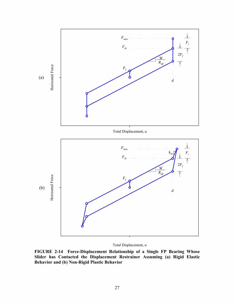
SECTION 3 FORMULATION OF THE FORCE-DISPLACEMENT RELATIONSHIP FOR
DOUBLE FP BEARINGS 3.1 Introduction This section demonstrates the formulation of the mechanical behavior and force-displacement relationship for double FP bearings. The treatment is largely based on work originally presented in Constantinou (2004) and Fenz and Constantinou (2006). Assuming the general configuration in which the coefficients of friction on each surface are unequal, behavior is comprised of three sliding regimes: (a) initial sliding only on the surface of least friction, (b) simultaneous sliding on both concave surfaces after friction is overcome on the surface of higher friction and (c) sliding on only one surface after the displacement restrainer is contacted on the other. The behavior in each sliding regime is derived from equilibrium and geometry of the bearing the deformed configuration. For simpler configurations having surfaces of equal friction (which are more common in practice) the behavior is readily obtained from simplification of the more general formulation. 3.2 Sliding Regime I Following the basic principles of operation described earlier, starting from rest motion initiates when the applied horizontal force, F , exceeds the friction force on the surface of least friction. Therefore, sliding begins on surface 1 (assuming that 1 2μ < μ ) when
1fF F= . The displaced shape and free body diagrams for sliding occurring on surface 1 only are shown in figure 3-1. Based on FBD III in the figure, the following relationships are obtained by considering equilibrium in the vertical and horizontal directions respectively: 1 1 1 1sin cos 0fW F S+ θ − θ = (3-1) 1 1 1 1cos sin 0fF S Fθ + θ − = (3-2) From geometry, the relative displacement of the slider on surface 1, 1u , is 1 1 1sineffu R= θ (3-3) Combining equations (3-1) through (3-3) and assuming that the relative displacement 1u is sufficiently small compared to the effective radius 1effR so that 1cos 1θ ≈ :
1 11
feff
WF u FR
= + (3-4)
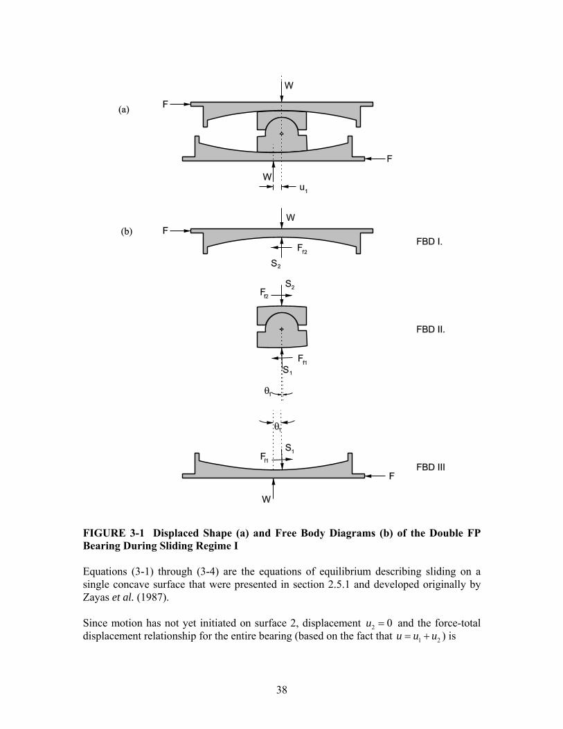
38
FIGURE 3-1 Displaced Shape (a) and Free Body Diagrams (b) of the Double FP Bearing During Sliding Regime I Equations (3-1) through (3-4) are the equations of equilibrium describing sliding on a single concave surface that were presented in section 2.5.1 and developed originally by Zayas et al. (1987). Since motion has not yet initiated on surface 2, displacement 2 0u = and the force-total displacement relationship for the entire bearing (based on the fact that 1 2u u u= + ) is

39
11
feff
WF u FR
= + (3-5)
Equation (3-5) describes also the hysteretic behavior of the single FP bearing having effective radius and friction the same as that of surface 1. As shown in figure 3-2, it is rigid linear with post elastic stiffness inversely proportional to the effective radius of surface 1 and strength equal to this surface’s friction force.
Total Displacement, u
Hor
izon
tal F
orce
Sliding Regime I: u < u*
WReff1
Ff1 2Ff1
FIGURE 3-2 Force-Displacement Relationship of Double FP for Sliding Regime I 3.3 Sliding Regime II With increasing applied horizontal force, sliding begins on surface 2 when 2fF F= . This occurs at displacement u∗ given by ( )2 1 1effu R∗ = μ − μ (3-6) Note that equation (3-6) is obtained by solving equation (3-5) for the displacement when
2fF F= . The displaced shape and free body diagrams for the double FP bearing after sliding has initiated on surface 2 are shown in figure 3-3. Comparing FBD III in figures 3-1 and 3-3,
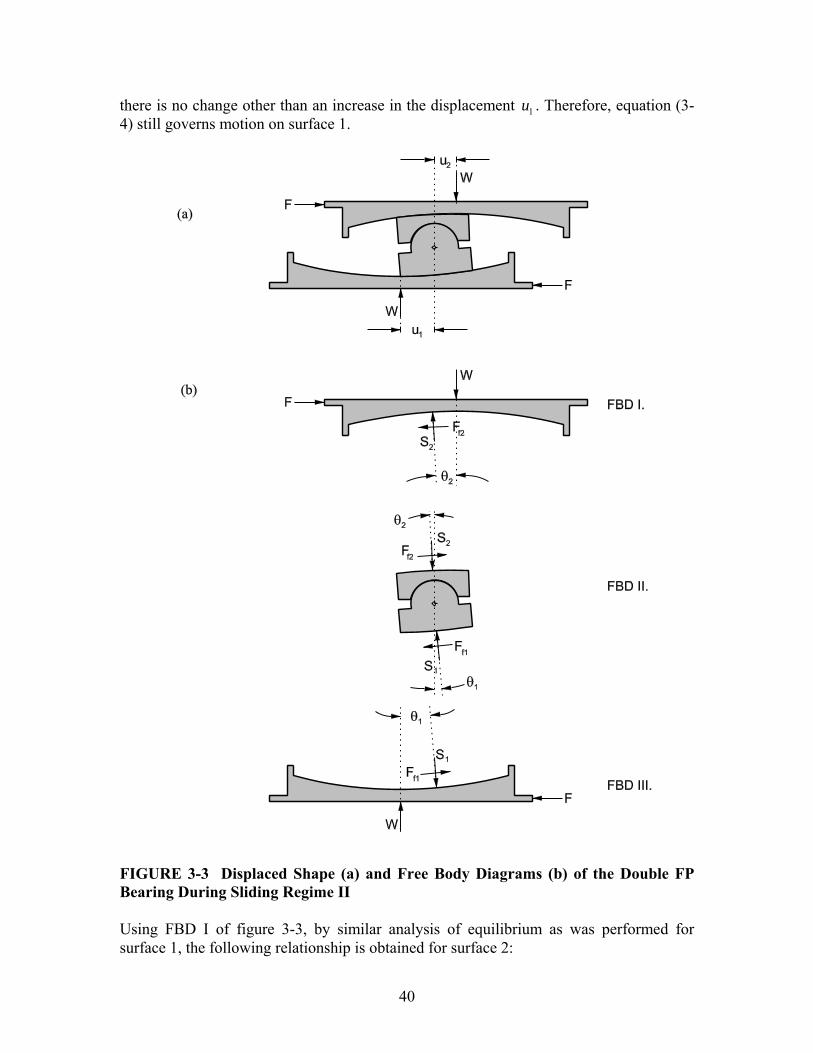
40
there is no change other than an increase in the displacement 1u . Therefore, equation (3-4) still governs motion on surface 1.
FIGURE 3-3 Displaced Shape (a) and Free Body Diagrams (b) of the Double FP Bearing During Sliding Regime II Using FBD I of figure 3-3, by similar analysis of equilibrium as was performed for surface 1, the following relationship is obtained for surface 2:
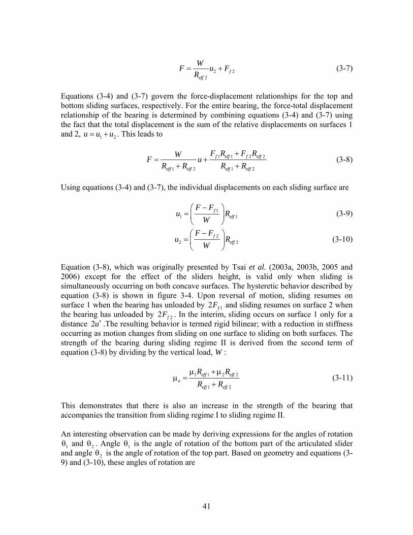
41
2 22
feff
WF u FR
= + (3-7)
Equations (3-4) and (3-7) govern the force-displacement relationships for the top and bottom sliding surfaces, respectively. For the entire bearing, the force-total displacement relationship of the bearing is determined by combining equations (3-4) and (3-7) using the fact that the total displacement is the sum of the relative displacements on surfaces 1 and 2, 1 2u u u= + . This leads to
1 1 2 2
1 2 1 2
f eff f eff
eff eff eff eff
F R F RWF uR R R R
+= +
+ + (3-8)
Using equations (3-4) and (3-7), the individual displacements on each sliding surface are
11 1
feff
F Fu R
W−⎛ ⎞
= ⎜ ⎟⎝ ⎠
(3-9)
22 2
feff
F Fu R
W−⎛ ⎞
= ⎜ ⎟⎝ ⎠
(3-10)
Equation (3-8), which was originally presented by Tsai et al. (2003a, 2003b, 2005 and 2006) except for the effect of the sliders height, is valid only when sliding is simultaneously occurring on both concave surfaces. The hysteretic behavior described by equation (3-8) is shown in figure 3-4. Upon reversal of motion, sliding resumes on surface 1 when the bearing has unloaded by 12 fF and sliding resumes on surface 2 when the bearing has unloaded by 22 fF . In the interim, sliding occurs on surface 1 only for a distance 2u∗ .The resulting behavior is termed rigid bilinear; with a reduction in stiffness occurring as motion changes from sliding on one surface to sliding on both surfaces. The strength of the bearing during sliding regime II is derived from the second term of equation (3-8) by dividing by the vertical load, W :
1 1 2 2
1 2
eff effe
eff eff
R RR R
μ + μμ =
+ (3-11)
This demonstrates that there is also an increase in the strength of the bearing that accompanies the transition from sliding regime I to sliding regime II. An interesting observation can be made by deriving expressions for the angles of rotation
1θ and 2θ . Angle 1θ is the angle of rotation of the bottom part of the articulated slider and angle 2θ is the angle of rotation of the top part. Based on geometry and equations (3-9) and (3-10), these angles of rotation are
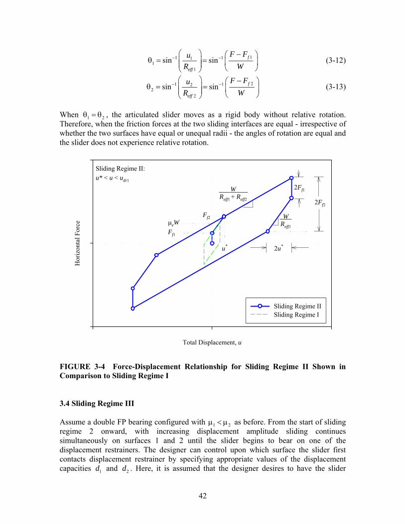
42
11 111
1
sin sin f
eff
F FuR W
− −⎛ ⎞ −⎛ ⎞
θ = =⎜ ⎟ ⎜ ⎟⎜ ⎟ ⎝ ⎠⎝ ⎠ (3-12)
21 122
2
sin sin f
eff
F FuR W
− −⎛ ⎞ −⎛ ⎞
θ = =⎜ ⎟ ⎜ ⎟⎜ ⎟ ⎝ ⎠⎝ ⎠ (3-13)
When 1 2θ = θ , the articulated slider moves as a rigid body without relative rotation. Therefore, when the friction forces at the two sliding interfaces are equal - irrespective of whether the two surfaces have equal or unequal radii - the angles of rotation are equal and the slider does not experience relative rotation.
Sliding Regime II: u* < u < udr1
Total Displacement, u
Hor
izon
tal F
orce
Sliding Regime IISliding Regime I
2Ff1
WReff1
Ff2
WReff1 + Reff2
Ff1
2Ff2
u*
eW
2u*
FIGURE 3-4 Force-Displacement Relationship for Sliding Regime II Shown in Comparison to Sliding Regime I 3.4 Sliding Regime III Assume a double FP bearing configured with 1 2μ < μ as before. From the start of sliding regime 2 onward, with increasing displacement amplitude sliding continues simultaneously on surfaces 1 and 2 until the slider begins to bear on one of the displacement restrainers. The designer can control upon which surface the slider first contacts displacement restrainer by specifying appropriate values of the displacement capacities 1d and 2d . Here, it is assumed that the designer desires to have the slider

43
contact the displacement restrainer of surface 1 prior to surface 2 and therefore have an increase in friction prior to achieving the total displacement capacity to better control displacements. To achieve this, it is necessary to have 1 2dr drF F< . In terms of displacement capacities this requirement can be expressed as
( )11 2 2 1 1
2
effeff
eff
Rd d R
R< + μ − μ (3-14)
At the instant the slider makes contact with the displacement restrainer on surface 1,
1 1u d= and the total displacement is
( )21 1 2 1 2
1
1 effdr eff
eff
Ru d R
R⎛ ⎞
= + − μ − μ⎜ ⎟⎜ ⎟⎝ ⎠
(3-15)
When the total displacement exceeds 1dru , sliding occurs only on surface 2 and the displaced shape and free body diagram are as shown in figure 3-5. It can be seen that the effect of contacting the displacement restrainer is the introduction of an additional bearing force on surface 1, 1rF . Therefore, for surface 1 the force-displacement relationship is
1 1 11
f reff
WF d F FR
= + + (3-16)
If the displacement restrainer is assumed rigid and elastic, throughout sliding regime III the relative displacement on surface 1 is 1 1u d= and the force exerted by the displacement restrainer is 1 1r drF F F= − (3-17) Examining FBD I of figure 3-5, nothing has changed from sliding regime II and the displacement 2u is still given by equation (3-10). Therefore, for an assumed rigid displacement restrainer, the force-displacement relationship is determined again by starting with the fact that 1 2u u u= + . Using 1 1u d= and equation (3-10) for 2u :
( )1 22
feff
WF u d FR
= − + (3-18)
Equation (3-18) demonstrates that the effect of contacting the displacement restrainer of surface 1 is an increase in stiffness from ( )1 2eff effW R R+ to 2effW R . Upon reversal of motion different orders of unloading are possible. Sliding resumes on surface 1 when the bearing has unloaded to 1 12dr fF F− and sliding resumes on surface 2 when the bearing has unloaded by 22 fF . Therefore, if
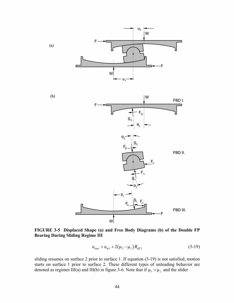
44
FIGURE 3-5 Displaced Shape (a) and Free Body Diagrams (b) of the Double FP Bearing During Sliding Regime III ( )max 1 2 1 22dr effu u R> + μ − μ (3-19) sliding resumes on surface 2 prior to surface 1. If equation (3-19) is not satisfied, motion starts on surface 1 prior to surface 2. These different types of unloading behavior are denoted as regimes III(a) and III(b) in figure 3-6. Note that if 1 2μ > μ and the slider
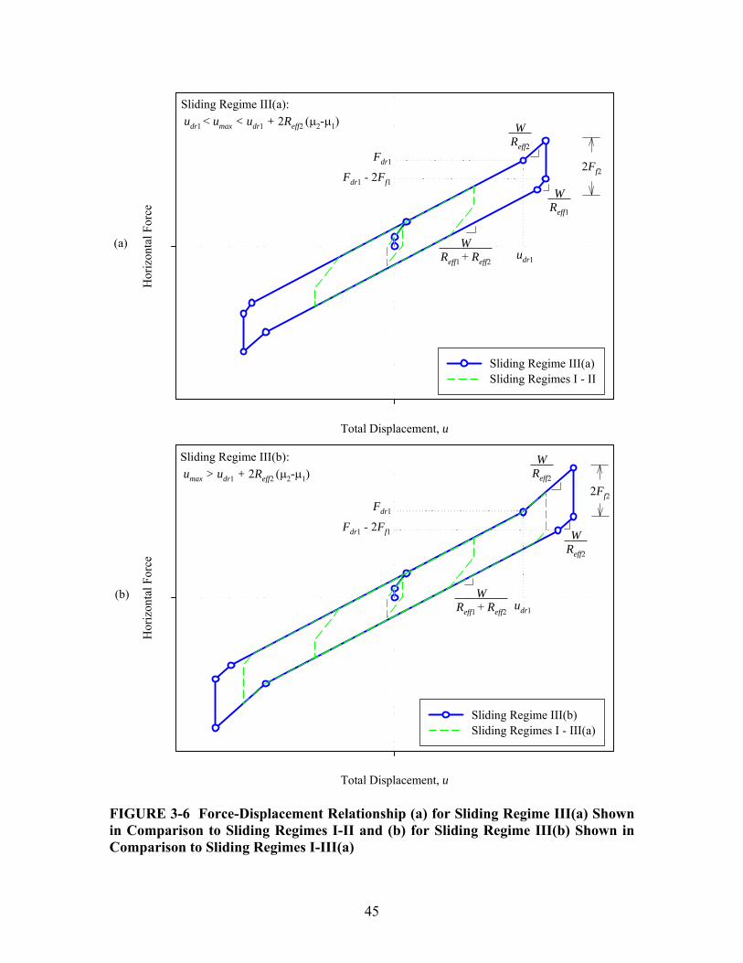
45
Total Displacement, u
Hor
izon
tal F
orce
Sliding Regime III(a)Sliding Regimes I - II
Sliding Regime III(b): umax > udr1 + 2Reff2 ( 2- 1)
Total Displacement, u
Hor
izon
tal F
orce
Sliding Regime III(b)Sliding Regimes I - III(a)
Sliding Regime III(a): udr1 < umax < udr1 + 2Reff2 ( 2- 1)
Fdr1
udr1
WReff2
WReff1
Fdr1 - 2Ff1
2Ff2
WReff1 + Reff2
WReff2
2Ff2
WReff2
Fdr1
Fdr1 - 2Ff1
udr1
WReff1 + Reff2
(a)
(b)
FIGURE 3-6 Force-Displacement Relationship (a) for Sliding Regime III(a) Shown in Comparison to Sliding Regimes I-II and (b) for Sliding Regime III(b) Shown in Comparison to Sliding Regimes I-III(a)

46
contacts the restrainer on surface 1 prior to surface 2, equation (3-19) will always be satisfied and there is only one order of unloading possible. If the displacement restrainer of surface 1 has some finite value of stiffness, 1drk , then the bearing force 1rF can be expressed as ( )1 1 1 1r drF k u d= − (3-20) Note that equation (3-20) is valid only for 1 1u d≥ and that 1 0rF = otherwise. This issue arises in modeling double FP bearings for dynamic analysis. The equations governing the force-displacement relationship of double FP bearings for all three sliding regimes are summarized in table 3-1. 3.5 Additional Comments 3.5.1 Behavior for Equal Friction Configurations Thus far the behavior of the double FP bearing has been described for the most general case in which 1 2μ ≠ μ . However, engineers wishing mainly to take advantage of the savings in material costs afforded by double concave bearings may elect to use 1 2μ = μ An additional benefit is that by sharing the displacements among two sliding surfaces, there is less increase in temperature at the sliding interface during sliding motion and accordingly less wear of the liner material. According to equation (3-6), when 1 2μ = μ the displacement u∗ goes to zero. Examining figure 3-4, one can envision that with 0u∗ = there is no transition in stiffness and the hysteretic behavior collapses from rigid-bilinear to rigid-linear. Upon initiation of motion, sliding regime II occurs instantaneously with no sliding regime I. Physically, this means that simultaneous sliding always occurs on surfaces 1 and 2. Prior to contacting the displacement restrainer the behavior is identical to that of a single FP bearing having effective radius equal to the sum of the effective radii of surfaces 1 and 2. Double FP bearings having equal friction have become quite popular since they provide considerable savings in material costs while still offering the same hysteretic behavior of the single FP bearing. Engineers familiar with traditional FP bearings can still use the same analysis methods and software as they have previously, with need only to change the specification of the radius of curvature from effR to 1 2eff effR R+ .
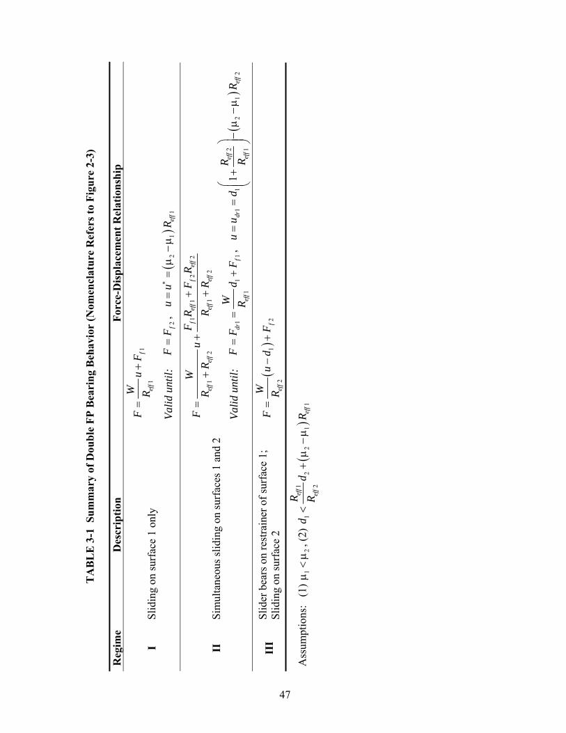
TA
BL
E 3
-1 S
umm
ary
of D
oubl
e FP
Bea
ring
Beh
avio
r (N
omen
clat
ure
Ref
ers t
o Fi
gure
2-3
) R
egim
e D
escr
iptio
n Fo
rce-
Dis
plac
emen
t Rel
atio
nshi
p
11
fef
f
WF
uF
R=
+
I Sl
idin
g on
surf
ace
1 on
ly
Valid
unt
il:
2fF
F=
,
()
21
1ef
fu
uR
∗=
=μ
−μ
11
22
12
12
fef
ff
eff
eff
eff
eff
eff
FR
FR
WF
uR
RR
R+
=+
++
II
Sim
ulta
neou
s slid
ing
on su
rfac
es 1
and
2
Valid
unt
il:
11
11
drf
eff
WF
Fd
FR
==
+,
(
)2
11
21
21
1ef
fdr
eff
eff
Ru
ud
RR
⎛⎞
==
+−
μ−
μ⎜
⎟⎜
⎟⎝
⎠
III
Slid
er b
ears
on
rest
rain
er o
f sur
face
1;
Slid
ing
on su
rfac
e 2
()
12
2f
eff
WF
ud
FR
=−
+
Ass
umpt
ions
: (1
) 1
2μ
<μ
, (2)
(
)1
12
21
12
eff
eff
eff
Rd
dR
R<
+μ
−μ
47
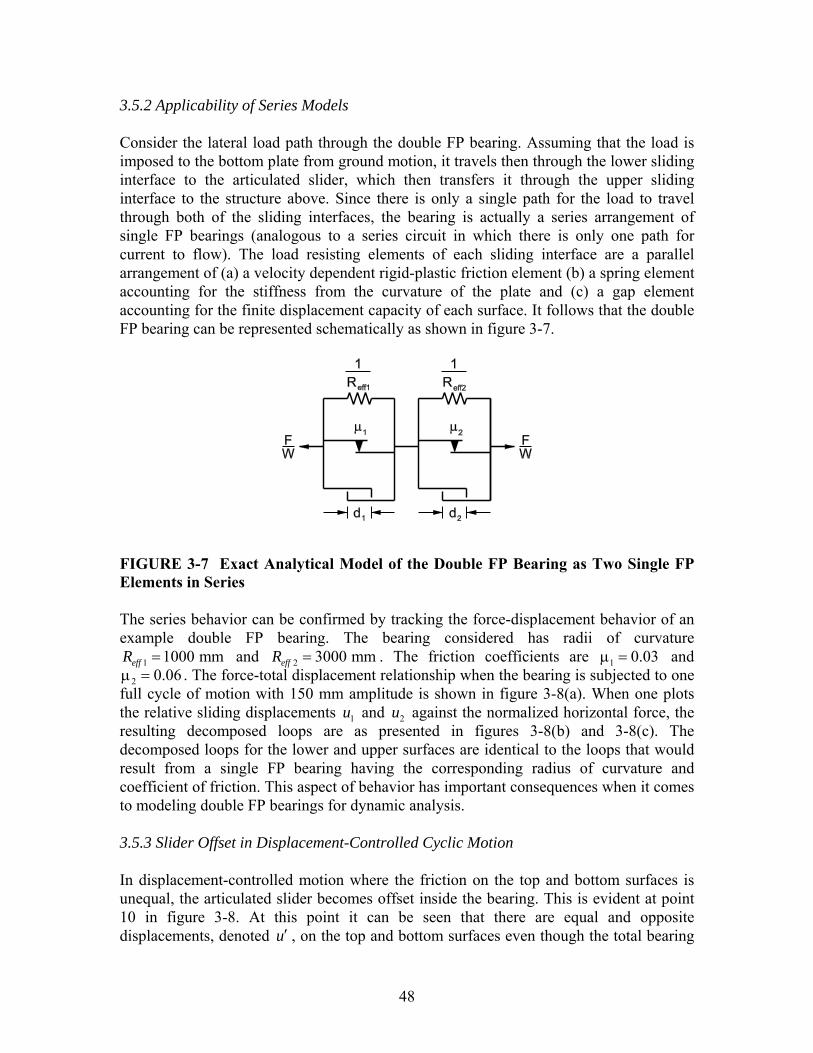
48
3.5.2 Applicability of Series Models Consider the lateral load path through the double FP bearing. Assuming that the load is imposed to the bottom plate from ground motion, it travels then through the lower sliding interface to the articulated slider, which then transfers it through the upper sliding interface to the structure above. Since there is only a single path for the load to travel through both of the sliding interfaces, the bearing is actually a series arrangement of single FP bearings (analogous to a series circuit in which there is only one path for current to flow). The load resisting elements of each sliding interface are a parallel arrangement of (a) a velocity dependent rigid-plastic friction element (b) a spring element accounting for the stiffness from the curvature of the plate and (c) a gap element accounting for the finite displacement capacity of each surface. It follows that the double FP bearing can be represented schematically as shown in figure 3-7.
FIGURE 3-7 Exact Analytical Model of the Double FP Bearing as Two Single FP Elements in Series The series behavior can be confirmed by tracking the force-displacement behavior of an example double FP bearing. The bearing considered has radii of curvature
1 1000 mmeffR = and 2 3000 mmeffR = . The friction coefficients are 1 0.03μ = and 2 0.06μ = . The force-total displacement relationship when the bearing is subjected to one
full cycle of motion with 150 mm amplitude is shown in figure 3-8(a). When one plots the relative sliding displacements 1u and 2u against the normalized horizontal force, the resulting decomposed loops are as presented in figures 3-8(b) and 3-8(c). The decomposed loops for the lower and upper surfaces are identical to the loops that would result from a single FP bearing having the corresponding radius of curvature and coefficient of friction. This aspect of behavior has important consequences when it comes to modeling double FP bearings for dynamic analysis. 3.5.3 Slider Offset in Displacement-Controlled Cyclic Motion In displacement-controlled motion where the friction on the top and bottom surfaces is unequal, the articulated slider becomes offset inside the bearing. This is evident at point 10 in figure 3-8. At this point it can be seen that there are equal and opposite displacements, denoted u′ , on the top and bottom surfaces even though the total bearing

49
displacement is zero. That is, 0u = and 1 2u u u′= − = ± . The offset originates because 1 2 eμ ≠ μ ≠ μ - when 1 0u = the normalized lateral force is 1μ , when 2 0u = the
normalized lateral force is 2μ , and when 0u = the normalized lateral force is eμ . Clearly, when the coefficients of friction are different these points will not be the same and the offset originates.
Total Displacement, u (mm)
-200 -150 -100 -50 0 50 100 150 200
Hor
izon
tal F
orce
Ver
tical
For
ce
-0.10
-0.08
-0.06
-0.04
-0.02
0.00
0.02
0.04
0.06
0.08
0.10
Bottom Displacement, u1 (mm)
-200 -100 0 100 200
Hor
izon
tal F
orce
Ver
tical
For
ce
-0.10
-0.05
0.00
0.05
0.10
Top Displacement, u2(mm)
-200 -100 0 100 200
Hor
izon
tal F
orce
Ver
tical
For
ce
-0.10
-0.05
0.00
0.05
0.10
0
1
2
3
4
5
6
7
8
9
10
0
1,9
23
4
56
7
8
10
0
1
23
4
5
6
7
8
10
9
11000
14000
11000
1 1000
1 3000
(a)
(c)(b)
FIGURE 3-8 Total (a) and Decomposed (b) and (c) Hysteresis Loops for a Configuration of Double FP Bearing Having Unequal Radii of Curvature and Unequal Coefficients of Friction
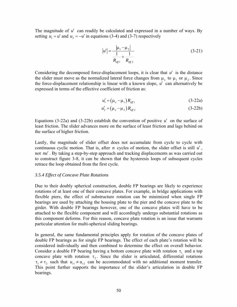
50
The magnitude of u′ can readily be calculated and expressed in a number of ways. By setting 1u u′= and 2u u′= − in equations (3-4) and (3-7) respectively
1 2
1 2
1 1eff eff
u
R R
μ − μ′ =
+ (3-21)
Considering the decomposed force-displacement loops, it is clear that u′ is the distance the slider must move as the normalized lateral force changes from eμ to 1μ or 2μ . Since the force-displacement relationship is linear with a known slope, u′ can alternatively be expressed in terms of the effective coefficient of friction as: ( )1 1 1e effu R′ = μ − μ (3-22a)
( )2 2 2e effu R′ = μ − μ (3-22b) Equations (3-22a) and (3-22b) establish the convention of positive u′ on the surface of least friction. The slider advances more on the surface of least friction and lags behind on the surface of higher friction. Lastly, the magnitude of slider offset does not accumulate from cycle to cycle with continuous cyclic motion. That is, after n cycles of motion, the slider offset is still u′ , not nu′ . By taking a step-by-step approach and tracking displacements as was carried out to construct figure 3-8, it can be shown that the hysteresis loops of subsequent cycles retrace the loop obtained from the first cycle. 3.5.4 Effect of Concave Plate Rotations Due to their doubly spherical construction, double FP bearings are likely to experience rotations of at least one of their concave plates. For example, in bridge applications with flexible piers, the effect of substructure rotation can be minimized when single FP bearings are used by attaching the housing plate to the pier and the concave plate to the girder. With double FP bearings however, one of the concave plates will have to be attached to the flexible component and will accordingly undergo substantial rotations as this component deforms. For this reason, concave plate rotation is an issue that warrants particular attention for multi-spherical sliding bearings. In general, the same fundamental principles apply for rotation of the concave plates of double FP bearings as for single FP bearings. The effect of each plate’s rotation will be considered individually and then combined to determine the effect on overall behavior. Consider a double FP bearing having a bottom concave plate with rotation 1τ and a top concave plate with rotation 2τ . Since the slider is articulated, differential rotations
1 2τ ≠ τ such that 1 2r ru u≠ can be accommodated with no additional moment transfer. This point further supports the importance of the slider’s articulation in double FP bearings.

51
Following the same formulation as for single FP bearings, the force-displacement relationship for rotated surface 1 is
( )1 1 11eff
WF u WR
= + μ ± τ (3-23)
where the last 1Wτ term is positive for motion to the right (since it requires more force to push up the incline) and negative for motion to the left (requires less force to push down the incline), assuming counter-clockwise rotation. Similarly, for the upper concave plate:
( )2 2 22eff
WF u WR
= + μ ± τ (3-24)
where the last 2Wτ term is positive for motion to the right (requires more force to push against the rotation) and negative for motion to the left (requires less force) assuming counter-clockwise rotation. Combining equations (3-23) and (3-24), for sliding regime II when motion is occurring on both surfaces, the force displacement relationship is
( ) ( )1 1 1 2 2 2
1 2 1 2
eff eff
eff eff eff eff
R R WWF uR R R R
⎡ ⎤μ ± τ + μ ± τ⎣ ⎦= ++ +
(3-25)
where the signs of the iWτ terms are determined as just described. Equations (3-23) through (3-25) show again that mathematically, the effect of the rotations is essentially a modification of the effective friction force exhibited. The total hysteresis loop shifts vertically by
( )1 1 2 2
1 2
Reff eff
eff eff
R Ws
R Rτ + τ
=+
(3-26)
when sliding is occurring on both surfaces. Furthermore, the decomposed loops of the lower and upper surfaces translate vertically by 1Wτ and 2Wτ respectively. In order to illustrate the effects of concave plate rotations on the behavior of double FP bearings, the example bearing considered in section 3.5.2 will be re-examined. Recall that it was configured to have the bottom sliding surface with 1 1000 mmeffR = and 1 0.03μ = and the top sliding surface with 2 3000 mmeffR = and 2 0.06μ = . The behavior will first be investigated for the case in which the concave plates are inclined such that 1 0.01τ = + and 2 0.01τ = + . The resulting behavior is shown in figure 3-9. Due to this rotation, the stable equilibrium position of the slider on surface 1 shifts by 1 10 mmru = − and shifts on surface 2 by 2 30 mmru = − . As a result, the stable equilibrium position of the entire bearing ends up shifting by 40 mmru = − .
52
Total Displacement, u (mm)
-200 -150 -100 -50 0 50 100 150 200
Hor
izon
tal F
orce
Ver
tical
For
ce
-0.15
-0.10
-0.05
0.00
0.05
0.10
0.15
LevelRotated
Bottom Displacement, u1 (mm)
-200 -100 0 100 200
Hor
izon
tal F
orce
Ver
tical
For
ce
-0.15
-0.10
-0.05
0.00
0.05
0.10
0.15
Top Displacement, u2(mm)
-200 -100 0 100 200
Hor
izon
tal F
orce
Ver
tical
For
ce
-0.15
-0.10
-0.05
0.00
0.05
0.10
0.15
(a)
(c)(b)
τ1Reff1 + τ2Reff2
Reff1 + Reff2
τ1Reff1 + τ2Reff2
Reff1 + Reff2
2μ12μ2
Reff1 = 1000mm, μ1 = 0.03, τ1 = +0.01 Reff2 = 3000mm, μ2 = 0.06, τ2 = +0.01
τ2
τ1
+τ2
+τ1
μe(+)
μe(-)
FIGURE 3-9 Total (a) and Decomposed (b) and (c) Hysteresis Loops for Example Bearing with 1τ = +0.01 and 2τ = +0.01 Starting from these modified stable equilibrium positions, sliding must initiate on surface 1 when 1F W= μ and sliding must initiate on surface 2 when 2F W= μ . As a result, by the time the slider moves to the unrotated stable equilibrium position of surface 1 ( )1 0u = , it has actually slid a total of 1 10 mmru = on this surface and the horizontal force is

53
1 1 1 11
reff
WF u W W WR
= + μ = τ + μ (3-27)
Equation (3-27) demonstrates that there is an upward shift of the decomposed loop of surface 1 by 1Wτ . Similarly for surface 2, by the time the slider reaches the position where 2 0u = , it has actually traveled 2 30 mmru = on surface 2, resulting in an upward shift of the decomposed loop by 2Wτ . Since the friction coefficients and post-elastic stiffness are not affected by the rotation, the magnitude of the displacement u∗ for which sliding occurs on surface 1 prior to starting on surface 2 remains unchanged. In this case, 1 230 mm 40 mmr ru u u∗ = < + = and simultaneous sliding starts on both surfaces before the original stable equilibrium position at 0u = is achieved. Due to the upward shift of both decomposed loops, the total loop shifts upwards by s W . There is no change in the stiffness exhibited during either sliding phase. Also, there is still the same slider offset at zero total displacement, u′ , as described in section 3.5.3. A second example for the same bearing is shown in figure 3-10. In this case, the lower plate has a rotation of 1 0.02τ = + and the upper plate rotation remains the same at
2 0.01τ = + . Again the total hysteresis loop shifts upward by s and the decomposed loops of surfaces 1 and 2 shift upward by 1Wτ and 2Wτ , respectively. In this case however, it is interesting to note that due to the rotation there are asymmetric displacements on the individual sliding surfaces. That is, the amplitudes of maximum positive and maximum negative displacement on the individual surfaces are different even though there is symmetric amplitude of total displacement. The offsets due to rotation on the lower and upper surfaces, denoted 1uτ′ and 2uτ′ are
1 1 2 21 1 1
1 2
eff effeff
eff eff
R Ru R
R Rτ
⎡ ⎤τ + τ′ = − τ⎢ ⎥
+⎢ ⎥⎣ ⎦ (3-28a)
1 1 2 22 2 2
1 2
eff effeff
eff eff
R Ru R
R Rτ
⎡ ⎤τ + τ′ = − τ⎢ ⎥
+⎢ ⎥⎣ ⎦ (3-28b)
In this example, from equations (3-28a) and (3-28b), 1 7.5 mmuτ′ = − and 2 7.5 mmuτ′ = . The rotation induced offsets on each surface are equal in magnitude and opposite in direction. Note that this phenomena was not observed in the previous example because for that specific combination of radii and rotations, by equations (3-28a) and (3-28b) ,
1 2 0 mmu uτ τ′ ′= = . These offsets will add to those offsets at zero total displacement noticed during noticed during displacement-controlled testing. Therefore, during displacement-controlled tests of rotated bearings, the offsets on the lower and upper surfaces at zero displacement are 1 1u uτ′ ′+ and 2 2u uτ′ ′+ respectively.
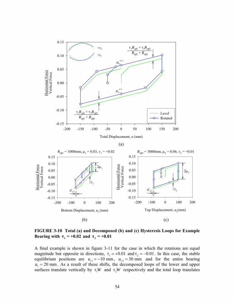
54
Total Displacement, u (mm)
-200 -150 -100 -50 0 50 100 150 200
Hor
izon
tal F
orce
Ver
tical
For
ce
-0.15
-0.10
-0.05
0.00
0.05
0.10
0.15
LevelRotated
Bottom Displacement, u1 (mm)
-200 -100 0 100 200
Hor
izon
tal F
orce
Ver
tical
For
ce
-0.15
-0.10
-0.05
0.00
0.05
0.10
0.15
Top Displacement, u2(mm)
-200 -100 0 100 200
Hor
izon
tal F
orce
Ver
tical
For
ce
-0.15
-0.10
-0.05
0.00
0.05
0.10
0.15
(a)
(c)(b)
τ1Reff1 + τ2Reff2
Reff1 + Reff2
τ1Reff1 + τ2Reff2
Reff1 + Reff2
2μ12μ2
u'τ1u'τ2
Reff1 = 1000mm, μ1 = 0.03, τ1 = +0.02 Reff2 = 3000mm, μ2 = 0.06, τ2 = +0.01
τ2
τ1
+τ2
+τ1
μe(+)
μe(-)
FIGURE 3-10 Total (a) and Decomposed (b) and (c) Hysteresis Loops for Example Bearing with 1τ = +0.02 and 2τ = +0.01 A final example is shown in figure 3-11 for the case in which the rotations are equal magnitude but opposite in directions, 1 0.01τ = + and 2 0.01τ = − . In this case, the stable equilibrium positions are 1 10 mmru = − , 2 30 mmru = and for the entire bearing
20 mmru = . As a result of these shifts, the decomposed loops of the lower and upper surfaces translate vertically by 1Wτ and 2Wτ respectively and the total loop translates
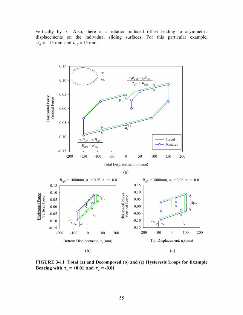
55
vertically by s . Also, there is a rotation induced offset leading to asymmetric displacements on the individual sliding surfaces. For this particular example,
1 15 mmuτ′ = − and 2 15 mmuτ′ = .
Total Displacement, u (mm)
-200 -150 -100 -50 0 50 100 150 200
Hor
izon
tal F
orce
Ver
tical
For
ce
-0.15
-0.10
-0.05
0.00
0.05
0.10
0.15
LevelRotated
Bottom Displacement, u1 (mm)
-200 -100 0 100 200
Hor
izon
tal F
orce
Ver
tical
For
ce
-0.15
-0.10
-0.05
0.00
0.05
0.10
0.15
Top Displacement, u2(mm)
-200 -100 0 100 200
Hor
izon
tal F
orce
Ver
tical
For
ce
-0.15
-0.10
-0.05
0.00
0.05
0.10
0.15
(a)
(c)(b)
-τ2
+τ1τ1Reff1 - τ2Reff2
Reff1 + Reff2
τ1Reff1 - τ2Reff2
Reff1 + Reff2
2μ12μ2
u'τ1u'τ2
Reff1 = 1000mm, μ1 = 0.03, τ1 =+ 0.01 Reff2 = 3000mm, μ2 = 0.06, τ2 = -0.01
τ2
τ1
μe(+)
μe(-)
FIGURE 3-11 Total (a) and Decomposed (b) and (c) Hysteresis Loops for Example Bearing with 1τ = +0.01 and 2τ = -0.01

56
It has been established that concave plate rotations change the stable equilibrium position of the slider on a given surface. This change must be taken into account when determining the displacement capacity of that surface. Since motion is starting from an offset position, the displacement capacities in each direction become i rid u+ and i rid u− . The effect on the displacement capacity is not negligible for longer period bearings. For example, for a 3 second period concave surface installed with an inclination of 0.01 rad (which is within typical tolerance) the shift in the stable equilibrium position is nearly 25 mm . As a result, there is asymmetric behavior for sliding regime III in the positive and negative directions. This is proven by solving for the total displacement when the slider contacts the displacement restrainer, driu . Assuming that the slider contacts the displacement restrainer of surface 1 first, this displacement is
( ) ( )21 1 2 1 2 1 2 2
1
1 effdr eff eff
eff
Ru d R R
R⎛ ⎞
= + − μ − μ + τ − τ⎜ ⎟⎜ ⎟⎝ ⎠
(3-29)
Equation (3-29) is obtained by solving for the displacement in equation (3-25) when the applied horizontal force is 1 1drF F W= + τ . Comparing equations (3-15) and (3-25), to more clearly see the effect of the concave plate rotation it can be written that ( )1, 1, 1 2 2dr rotated dr level effu u R= + τ − τ (3-30) where 1,dr levelu is 1dru given by equation (3-15). To illustrate this, consider a double FP bearing with 1 2 2000 mmeff effR R= = ,
1 2 0.05μ = μ = , 1 75 mmd = and 2 1d d . The hysteretic behavior in the level configuration and with a bottom plate rotation of 0.01 rad are compared in figure 3-12 for a displacement amplitude of 200 mm. Based on the figure, it is observed that due to the rotation of surface 1, the stable equilibrium position of the slider on this surface shifts by
1 20 mmru = − . Therefore, the slider comes into contact with the displacement restrainer after travelling 95 mm in the positive direction and only 55 mm in the negative direction. As a result, the force-displacement loop for the entire bearing and the decomposed loop for surface 1 are asymmetric. Based on equation (3-30),
1, 1, 20 mmdr rotated dr levelu u= + in both the positive and negative directions. So whereas in the level configuration 1 150 mmdru = ± , now in the inclined configuration
1 170 mm and -130 mmdru = + . Also note that even though friction on each surface is the same, there are offsets on each surface at zero total displacement ( )1 2 10 mmu uτ τ′ ′= − = − due to the rotation.

57
Total Displacement, u (mm)
-300 -200 -100 0 100 200 300
Hor
izon
tal F
orce
Ver
tical
For
ce
-0.15
-0.10
-0.05
0.00
0.05
0.10
0.15
LevelRotated
Bottom Displacement, u1 (mm)
-200 -100 0 100 200
Hor
izon
tal F
orce
Ver
tical
For
ce
-0.15
-0.10
-0.05
0.00
0.05
0.10
0.15
Top Displacement, u2(mm)
-200 -100 0 100 200
Hor
izon
tal F
orce
Ver
tical
For
ce
-0.15
-0.10
-0.05
0.00
0.05
0.10
0.15
(a)
(c)(b)
τ1Reff1 + τ2Reff2
Reff1 + Reff2
τ1Reff1 + τ2Reff2
Reff1 + Reff2
2μ12μ2
u'τ1 u'τ2
Reff1 = 2000mm, μ1 = 0.05, τ1 = +0.01 Reff2 = 2000mm, μ2 = 0.05, τ2 = 0
τ1
μe(+)
μe(-)
τ2 = 0
+τ1
d1-ur1 d1+ur1
FIGURE 3-12 Total (a) and Decomposed (b) and (c) Hysteresis Loops for Example Bearing with 1τ = +0.01 and 2τ = 0 and Slider that Contacts the Displacement Restrainer 3.5.5 Modeling for Dynamic Analysis Various options exist for modeling of double FP bearings in programs used for response history analysis of seismically isolated structures. For the simplest case of 1 2eff effR R= and 1 2μ = μ , the behavior of the bearing can be modeled as that of a single FP bearing

58
with radius of curvature 1 2eff effR R+ and coefficient of friction as determined by experiment. The velocity dependence of the coefficient of friction is described by ( ) ( )max max min expf f f uμ = − − −α (3-31) where u is the sliding velocity, maxf and minf are the sliding coefficients of friction at large velocity and nearly zero sliding velocity respectively and α is a parameter that controls the transition from maxf to minf . This relationship was proposed originally by Mokha et al. (1990). Typically maxf is determined in the prototype bearing testing program and the parameters minf and α are selected on the basis of available experimental results. For example, refer to Constantinou et al. (1999 and 2007a). When determining the velocity dependence of the coefficient of friction for each interface, the relevant velocities are the sliding velocities on each concave surface - not the total velocity. For double FP bearings of equal radii and friction, the sliding velocities on each surface are equal and have magnitude 2u . Therefore, equation (3-31) still applies provided a value 2α is specified. This is because in both cases the value of the exponential is ( )exp 2uα . For example, a value of 100α = sec/m is often used for the composite friction material in traditional FP bearings. To model a double FP bearing with the same type of sliding material, the value 50α = sec/m should be specified in the analysis program. For the general case of a double FP bearing with unequal radii and unequal friction, the behavior can be modeled using two single concave FP bearing elements acting in series. By defining two separate elements with the radii of curvature and coefficients of friction of each concave surface and connecting them in series with a point mass representing the articulated slider, the overall behavior is obtained. Velocity dependence of the coefficient of friction is still governed by equation (3-31), though the velocities of each isolator element represent the true sliding velocities on each surface. Accordingly, the rate parameter α need not be modified. 3.5.6 Values of Property Modification Factors The concept of bounding analysis on the basis of system property modification factors or λ -factors is originally described in Constantinou et al. (1999) and employed beginning in the 1999 AASHTO Guide Specifications for Seismic Isolation Design (AASHTO, 1999). The method is a systematic procedure for calculating upper and lower bound values for the mechanical properties of seismic isolators to account for aging, contamination, history of loading, temperature and other effects. For FP bearings, only the coefficient of friction is affected by the aforementioned effects. The system property modification factors for double FP bearings are the same as those for traditional FP bearings except for the contamination factor. Separate factors should be considered for the upper and lower concave surfaces, respectively. Anticipating that the bearings will be sealed (as unsealed bearings with a concave stainless steel surface facing

59
up are not permitted in the AASHTO Guide Specifications), the contamination factors will be 1 1.1cλ = for the lower (upward facing) surface and 2 1.0cλ = for the upper (downward facing) surface. When response history analysis is performed with each bearing explicitly modeled as two spherical sliding surfaces in series, the two different contamination factors can be directly utilized in adjusting the properties of each sliding surface. However, when simplified calculations are performed, a contamination factor for the entire system is needed. This factor may be derived on the basis of equation (3-11) that combines the contributions of the frictional forces from the two sliding interfaces:
1 1 1 2 2 2
1 1 2 2
c eff c effc
eff eff
R RR R
λ μ + λ μλ =
μ + μ (3-32)
For the most common case of bearings with equal radii and friction,
( )1 2 2 1.05c c cλ = λ + λ = . 3.5.7 P − Δ Moment Transfer In the traditional FP bearing, the P − Δ moment (moment resulting from vertical load P through the total bearing displacement Δ ) is transferred to the structure or foundation on the side of the concave plate. In contrast, for double FP bearings this moment is divided among the two concave plates. The moments transferred to the top and bottom concave plates are 1P u× and 2P u× respectively, where 1u and 2u are the relative displacements on each surface. For bearings with 1 2eff effR R≈ and 1 2μ ≈ μ , the displacements 1u and 2u are each effectively equal to 2Δ and the moment transferred through each concave plate is 2PΔ . Though double FP bearings require the boundary elements both above and below to resist the P − Δ moment, the magnitude of the moment that must be resisted is considerably less.


61
SECTION 4 FORMULATION OF THE FORCE-DISPLACEMENT RELATIONSHIP FOR
TRIPLE FP BEARINGS 4.1 Introduction This section demonstrates how the force-displacement relationship is derived for a triple FP bearing in the fully adaptive configuration. The presentation follows that of Fenz and Constantinou (2007a). Referring to the nomenclature established in figure 2-5, the fully adaptive triple FP bearing is configured as follows:
1. Large and equal effective radii for the outer concave plates and small and equal effective radii for the inner slide plates, 1 4 2 3eff eff eff effR R R R= = . This condition, when combined with appropriate specification of friction coefficients will result in the desirable transitions in stiffness throughout the course of motion. Note there is no hard and fast requirement that 1 4eff effR R= or 2 3eff effR R= (the equations are formulated in general to account for configurations of unequal radii), however for simplicity of manufacture these radii will be equal in most cases.
2. The coefficients of friction are selected so that the bearing exhibits high stiffness and low friction initially and subsequently decreases in stiffness and increases in effective friction as the amplitude of displacement increases. This is accomplished by using friction materials that give 2 3 1 4μ = μ < μ < μ .
3. The displacement capacities of each surface are selected so that there is gradual stiffening at large displacement. The slider should contact the displacement restrainer on surfaces 1 and 4 prior to surfaces 2 and 3. Provided that motion initiates on surfaces 2 and 3 prior to surfaces 1 and 4, this is guaranteed as long as 1 2f drF F< and 4 3f drF F< . In terms of displacements, this condition is ( )2 1 2 2effd R> μ − μ and ( )3 4 3 3effd R> μ − μ .
4. Sliding should initiate on the surface of highest friction prior to the onset of any stiffening, that is 4 1f drF F< . In terms of displacements, this condition is satisfied provided that ( )1 4 1 1effd R> μ − μ . This is to avoid a situation in which the bearing stiffens, then softens, then stiffens again, which would occur if
1 4dr fF F< . The bearing would stiffen upon contacting the displacement restrainer of surface 1, soften when sliding started on surface 4, and then stiffen again upon contacting the displacement restrainer of surface 4.
The approach taken is to formulate the force-displacement behavior using these assumptions to describe the most general configuration that can be reasonably implemented. Subsequently, the collapse to simpler types of hysteretic behavior for configurations of triple FP bearing having equal friction is described. Similar to the double FP bearing having surfaces of equal friction, the simpler configurations are likely to be more widely implemented due to their economic benefits and less complex

62
behavior. However, there may be situations in which the engineer desires high performance at the expense of a more elaborate analysis. Moreover, understanding the behavior in the most general configuration and the influence of each design parameter gives the confidence necessary to implement the simpler configurations in practical applications. Lastly, the modified single FP bearing is discussed because it is a much simpler adaptation of the triple FP bearing but operates on essentially the same physical principles. Although it is in itself a viable type of isolation system, its treatment in this report is primarily as means of verification of the mechanical behavior of the triple FP. 4.2 Sliding Regime I Sliding regime I consists of sliding on surfaces 2 and 3 and no sliding on surfaces 1 and 4. The basic principles of operation described earlier dictate that starting from rest, motion will initiate when the horizontal force exceeds the friction force on the surface(s) of least friction. Therefore, sliding begins on surfaces 2 and 3 when 2 3f fF F F= = . The displaced shape and free body diagrams of the components of the bearing during this regime are shown in figure 4-1. Based on FBD III of figure 4-1(b), the following relationships are obtained by considering equilibrium in the vertical and horizontal directions respectively: 1 2 2 2 2sin cos 0fS F S+ θ − θ = (4-1a) 2 2 2 2 1cos sin 0f fF S Fθ + θ − = (4-1b) Also, from FBD IV of figure 4-1(b), 1fF F= (4-2a) 1W S= (4-2b) From geometry, the relative displacement of the slider on surface 2, 2u , is 2 2 2sineffu R= θ (4-3) Combining equations (4-1) through (4-3) and assuming that the relative displacement 2u is sufficiently small compared to the effective radius 2effR so that 2cos 1θ ≈ :
2 22
feff
WF u FR
= + (4-4)
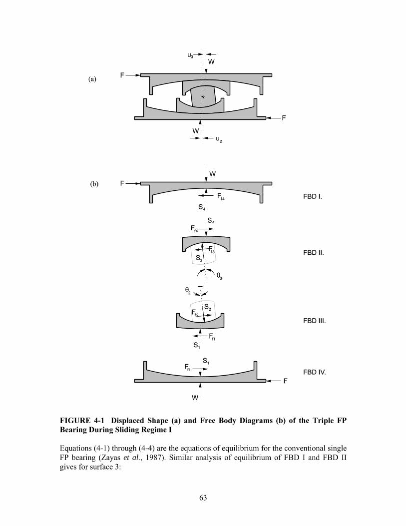
63
FIGURE 4-1 Displaced Shape (a) and Free Body Diagrams (b) of the Triple FP Bearing During Sliding Regime I Equations (4-1) through (4-4) are the equations of equilibrium for the conventional single FP bearing (Zayas et al., 1987). Similar analysis of equilibrium of FBD I and FBD II gives for surface 3:

64
3 33
feff
WF u FR
= + (4-5)
The force-total displacement relationship for the bearing during sliding regime I is determined by combining equations (4-4) and (4-5) based on the fact that the total displacement u is the sum of the displacements 2u and 3u , as 1 4 0u u= = , resulting in
2 2 3 3
2 3 2 3
f eff f eff
eff eff eff eff
F R F RWF uR R R R
+= +
+ + (4-6)
Upon reversal of motion, the bearing unloads by 2 32 ( 2 )f fF F= and sliding initiates again on surfaces 2 and 3. As shown in figure 4-2, the hysteretic behavior is rigid-linear with post-elastic stiffness equal to the sum of the effective radii of surfaces 2 and 3 and strength equal to the average coefficient of friction on these two surfaces. The behavior is identical to a double FP bearing with concave surfaces of equal radii and equal friction.
Sliding Regime I: umax < u*
Total Displacement, u
Hor
izon
tal F
orce
WReff2+ Reff3
2Ff2 ( =2Ff3)Ff2 (= Ff3)
FIGURE 4-2 Force-Displacement Relationship During Sliding Regime I

65
4.3 Sliding Regime II When 1fF F= , motion begins on surface 1, marking the start of sliding regime II. The transition occurs at displacement u∗ given by ( ) ( )1 2 2 1 3 3eff effu R R∗ = μ − μ + μ − μ (4-7) Equation (4-7) is obtained by solving equation (4-6) for the displacement when 1fF F= . The displaced shape and free body diagrams for sliding regime II are shown in figure 4-3. The rotation of the lower slide plate with respect to the lower concave plate is 1θ and the rotation of the rigid slider with respect to the lower slide plate is 2θ . When the angles are defined in this way, the relative displacements 1u and 2u are 1 1 1sineffu R= θ (4-8a) 2 2 2sineffu R= θ (4-8b) From FBD IV of figure 4-3(b) the equilibrium equations of the single FP bearing are obtained, leading to the following relationship governing motion on surface 1:
1 11
feff
WF u FR
= + (4-9)
Although small in magnitude, rotation of the lower slide plate when sliding is occurring on surface 1 has a significant impact on behavior. The angle that the rigid slider makes with respect to the vertical direction is now the sum of angles 1θ and 2θ , as reflected in the equations of equilibrium from FBD III of figure 4-3(b): ( ) ( )1 1 2 1 2 2 1 2 1 1cos sin cos sin 0f fS F S Fθ + θ + θ − θ + θ − θ = (4-10a)
( ) ( )2 1 2 2 1 2 1 1 1 1sin cos sin cos 0f fS F S Fθ + θ + θ + θ − θ − θ = (4-10b) Using equations (4-8) - (4-10) and the assumptions that the individual angles 1θ and
2θ are small so that 1 2cos cos 1θ ≈ θ ≈ and 1 2sin sin 0θ × θ ≈ , for surface 2 it is found that
1 22
1 2f
eff eff
u uF W FR R
⎛ ⎞= + +⎜ ⎟⎜ ⎟
⎝ ⎠ (4-11)
Substituting equation (4-9) into equation (4-11): ( )2 1 2 2effu R= μ − μ (4-12) Equation (4-12) is important because it reveals that the displacement on surface 2 is constant with magnitude equal to the value of 2u when motion transitions from sliding

66
regime I to sliding regime II (solve equation (4-4) for 2u with 1fF F= ). This means that the instant sliding starts on surface 1, it stops on surface 2.
FIGURE 4-3 Displaced Shape (a) and Free Body Diagrams (b) of the Triple FP Bearing During Sliding Regime II

67
Inspection of FBD I and FBD II of figure 4-3(b) shows that there is no change from FBD I and FBD II of figure 4-1(b), other than that the angle 3θ is larger due to the increase of displacement 3u . Therefore, there is no sliding on surface 4 and motion on surface 3 is still governed by equation (4-5). So with sliding occurring on surfaces 1 and 3 only, the force-total displacement relationship for sliding regime II determined based on equations (4-5), (4-9) and (4-11) is
( )1 1 2 2 2 3 3
1 3 1 3
f eff eff f eff f eff
eff eff eff eff
F R R F R F RWF uR R R R
− + += +
+ + (4-13)
This relationship is shown in figure 4-4. Upon reversal of motion, the bearing unloads by
2 32 ( 2 )f fF F= and motion resumes on surfaces 2 and 3. Motion continues on surfaces 2 and 3 for a distance of 2u∗ until the bearing has unloaded by 12 fF , at which point sliding starts again on surface 1 and stops on surface 2. Sliding then continues on surfaces 1 and 3. In comparison to sliding regime I, transition to sliding regime II is accompanied by a reduction in stiffness and an increase in effective friction.
Sliding Regime II: u* < umax < u**
Total Displacement, u
Hor
izon
tal F
orce
Sliding Regime IISliding Regime I
Ff1
u*
WReff1 + Reff3
WReff2 + Reff3
2Ff1
2Ff2
WReff1 + Reff3
2u*
FIGURE 4-4 Force-Displacement Relationship During Sliding Regime II Shown in Relation to Sliding Regime I
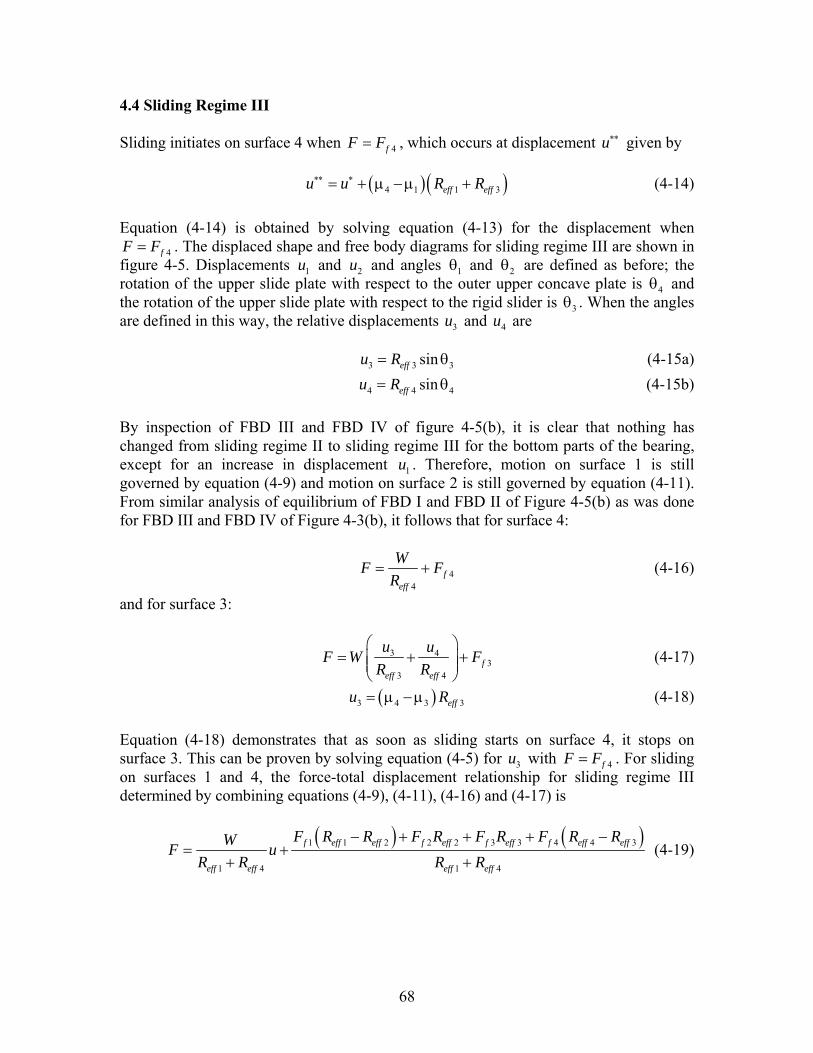
68
4.4 Sliding Regime III Sliding initiates on surface 4 when 4fF F= , which occurs at displacement u∗∗ given by ( )( )4 1 1 3eff effu u R R∗∗ ∗= + μ − μ + (4-14) Equation (4-14) is obtained by solving equation (4-13) for the displacement when
4fF F= . The displaced shape and free body diagrams for sliding regime III are shown in figure 4-5. Displacements 1u and 2u and angles 1θ and 2θ are defined as before; the rotation of the upper slide plate with respect to the outer upper concave plate is 4θ and the rotation of the upper slide plate with respect to the rigid slider is 3θ . When the angles are defined in this way, the relative displacements 3u and 4u are 3 3 3sineffu R= θ (4-15a) 4 4 4sineffu R= θ (4-15b) By inspection of FBD III and FBD IV of figure 4-5(b), it is clear that nothing has changed from sliding regime II to sliding regime III for the bottom parts of the bearing, except for an increase in displacement 1u . Therefore, motion on surface 1 is still governed by equation (4-9) and motion on surface 2 is still governed by equation (4-11). From similar analysis of equilibrium of FBD I and FBD II of Figure 4-5(b) as was done for FBD III and FBD IV of Figure 4-3(b), it follows that for surface 4:
44
feff
WF FR
= + (4-16)
and for surface 3:
3 43
3 4f
eff eff
u uF W FR R
⎛ ⎞= + +⎜ ⎟⎜ ⎟
⎝ ⎠ (4-17)
( )3 4 3 3effu R= μ − μ (4-18) Equation (4-18) demonstrates that as soon as sliding starts on surface 4, it stops on surface 3. This can be proven by solving equation (4-5) for 3u with 4fF F= . For sliding on surfaces 1 and 4, the force-total displacement relationship for sliding regime III determined by combining equations (4-9), (4-11), (4-16) and (4-17) is
( ) ( )1 1 2 2 2 3 3 4 4 3
1 4 1 4
f eff eff f eff f eff f eff eff
eff eff eff eff
F R R F R F R F R RWF uR R R R
− + + + −= +
+ + (4-19)

69
FIGURE 4-5 Displaced Shape (a) and Free Body Diagrams (b) of the Triple FP Bearing During Sliding Regime III This relationship is shown in figure 4-6. Compared to regimes I and II, transition to sliding regime III is accompanied by a reduction in stiffness and an increase in effective

70
friction. When motion reverses, the bearing unloads by 2 32 ( 2 )f fF F= and sliding resumes on surfaces 2 and 3. Motion continues on surfaces 2 and 3 for a distance of 2u∗ until the bearing has unloaded by 12 fF , at which point sliding starts on surface 1 and stops on surface 2. From this point, motion continues on surfaces 1 and 3 for a distance of 2 2u u∗∗ ∗− until the bearing has unloaded by 42 fF . At this point, motion resumes on surface 4 (and stops on surface 3) and sliding on surfaces 1 and 4 occurs.
Sliding Regime III: u** < umax < udr1
Total Displacement, u
Hor
izon
tal F
orce
Sliding Regime IIISliding Regimes I - II
Ff4
u**
WReff1 + Reff4
WReff1 + Reff4
WReff2 + Reff3
WReff1 + Reff3
2Ff2
2Ff4
2Ff1
2u**
FIGURE 4-6 Force-Displacement Relationship During Sliding Regime III Shown in Relation to Sliding Regimes I-and II 4.5 Sliding Regime IV Stiffening behavior of the triple FP bearing at large displacements is achieved by stopping motion on surfaces with large effective radius and forcing it to occur on surfaces with smaller effective radius. Sliding regime IV begins when the motion changes from sliding on surface 1 and 4 to sliding on surfaces 2 and 4, which occurs when contact is made with the displacement restrainer on surface 1. At this point, the displacement on surface 1 is 1 1u d= and the horizontal force, 1drF , is
1 1 11
dr feff
WF d FR
= + (4-20)

71
The transition between sliding regimes occurs at a total displacement of 1dru , given by
( )( )41 1 4 1 1 4
1
1 effdr eff eff
eff
Ru u d R R
R∗∗
⎛ ⎞= + + − μ − μ +⎜ ⎟⎜ ⎟
⎝ ⎠ (4-21)
Equation (4-21) is obtained by solving equation (4-19) for u with 1drF F= . The displaced shape and free body diagrams for motion during regime IV are given in figure 4-7. In FBD III and FBD IV of figure 4-7, it is shown that the effect of the displacement restrainer contacting the slider on surface 1 is to introduce an additional force on the slider, 1rF . It is assumed that the displacement restrainer is rigid, and therefore from FBD IV of figure 4-7, the force displacement relationship governing motion on surface 1 is
1 1 11
f reff
WF d F FR
= + + (4-22)
There is no additional displacement on surface 1 and equilibrium is maintained by an increase in the restrainer force, 1rF , as the applied horizontal force, F , is increased. Using FBD III and FBD IV of figure 4-7(b), the force displacement relationship governing motion on surface 2 is
1 22
1 2f
eff eff
d uF W FR R
⎛ ⎞= + +⎜ ⎟⎜ ⎟
⎝ ⎠ (4-23)
This demonstrates that sliding resumes on surface 2 when the displacement restrainer is contacted on surface 1. Equation (4-23) is simply equation (4-11) with 1 1u d= . Nothing has changed on the upper surfaces so motion on surfaces 3 and 4 is still governed by equations (4-17) and (4-16) respectively. Therefore, with sliding occurring on surfaces 2 and 4 the force-total displacement relationship is
( )1 1 12 4 1
dr feff eff eff
W WF u u d FR R R
= − + ++
(4-24)
This relationship is shown in figure 4-8. Upon reversal of motion, the bearing unloads by
2 32 ( 2 )f fF F= and motion resumes on surfaces 2 and 3. As described in figure 2-10, after the slider contacts the displacement restrainer on surface 1, motion will not start on this surface until the bearing has unloaded by 1 12r fF F+ to
1 11
feff
WF d FR
= − (4-25)
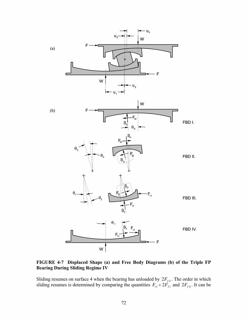
72
FIGURE 4-7 Displaced Shape (a) and Free Body Diagrams (b) of the Triple FP Bearing During Sliding Regime IV Sliding resumes on surface 4 when the bearing has unloaded by 42 fF . The order in which sliding resumes is determined by comparing the quantities 1 12r fF F+ and 42 fF . It can be
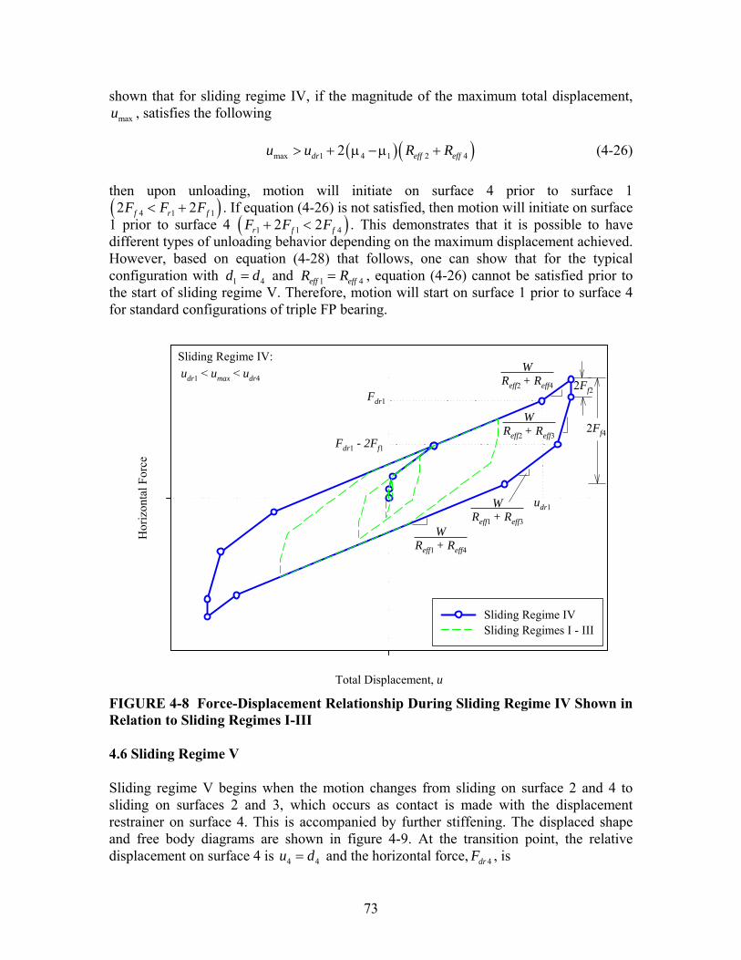
73
shown that for sliding regime IV, if the magnitude of the maximum total displacement, maxu , satisfies the following
( )( )max 1 4 1 2 42dr eff effu u R R> + μ − μ + (4-26) then upon unloading, motion will initiate on surface 4 prior to surface 1 ( )4 1 12 2f r fF F F< + . If equation (4-26) is not satisfied, then motion will initiate on surface 1 prior to surface 4 ( )1 1 42 2r f fF F F+ < . This demonstrates that it is possible to have different types of unloading behavior depending on the maximum displacement achieved. However, based on equation (4-28) that follows, one can show that for the typical configuration with 1 4d d= and 1 4eff effR R= , equation (4-26) cannot be satisfied prior to the start of sliding regime V. Therefore, motion will start on surface 1 prior to surface 4 for standard configurations of triple FP bearing.
Sliding Regime IV:udr1 < umax < udr4
Total Displacement, u
Hor
izon
tal F
orce
Sliding Regime IVSliding Regimes I - III
Fdr1
Fdr1 - 2Ff1
udr1
WReff2 + Reff4
WReff1 + Reff4
WReff2 + Reff3
WReff1 + Reff3
2Ff2
2Ff4
FIGURE 4-8 Force-Displacement Relationship During Sliding Regime IV Shown in Relation to Sliding Regimes I-III 4.6 Sliding Regime V Sliding regime V begins when the motion changes from sliding on surface 2 and 4 to sliding on surfaces 2 and 3, which occurs as contact is made with the displacement restrainer on surface 4. This is accompanied by further stiffening. The displaced shape and free body diagrams are shown in figure 4-9. At the transition point, the relative displacement on surface 4 is 4 4u d= and the horizontal force, 4drF , is
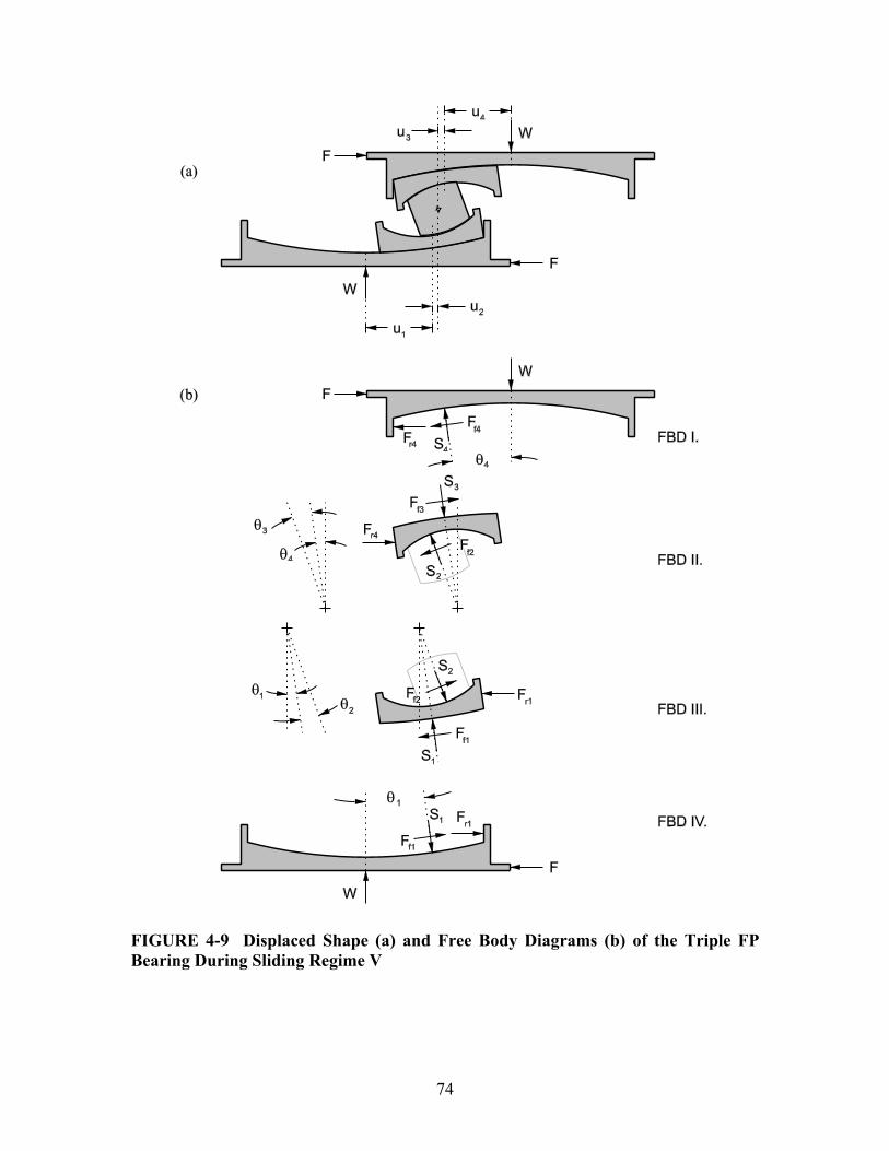
74
FIGURE 4-9 Displaced Shape (a) and Free Body Diagrams (b) of the Triple FP Bearing During Sliding Regime V
75
4 4 44
dr feff
WF d FR
= + (4-27)
The transition between sliding regimes occurs at a total displacement of 4dru , given by
( )4 14 1 4 1 2 4
4 1dr dr eff eff
eff eff
d du u R RR R
⎡ ⎤⎛ ⎞ ⎛ ⎞= + + μ − + μ +⎢ ⎥⎜ ⎟ ⎜ ⎟⎜ ⎟ ⎜ ⎟⎢ ⎥⎝ ⎠ ⎝ ⎠⎣ ⎦
(4-28)
From similar analysis of equilibrium of FBD I and FBD II of figure 4-9(b) as was done for FBD III and FBD IV of figure 4-7(b), it follows that for surface 4:
4 4 44
f reff
WF d F FR
= + + (4-29)
and for surface 3
343
4 3f
eff eff
udF W FR R
⎛ ⎞= + +⎜ ⎟⎜ ⎟
⎝ ⎠ (4-30)
As with the bottom part of the bearing, equation (4-30) reveals that sliding resumes on surface 3 the instant contact is made with the displacement restrainer on surface 4. Nothing has changed on the lower part of the bearing, motion is still occurring on surface 2 with the slider bearing on the displacement restrainer on surface 1. Therefore, combining the force displacement relationships for surfaces 1 through 4 gives
( )4 4 42 3 4
dr feff eff eff
W WF u u d FR R R
= − + ++
(4-31)
This is shown in figure 4-10. When the motion reverses, the bearing will unload by
2 32 ( 2 )f fF F= and sliding will occur on surfaces 2 and 3. Motion resumes on surface 1 when the bearing unloads to 1 12dr fF F− and motion resumes on surface 4 when the bearing unloads to 4 42dr fF F− . Since the former is always larger than the latter (assuming the standard configuration), when the bearing unloads from maximum displacement max 4dru u> , sliding will initiate on surface 1 prior to surface 4. The equations governing the force-displacement relationship of triple FP bearings for all five sliding regimes are summarized in table 4-1.
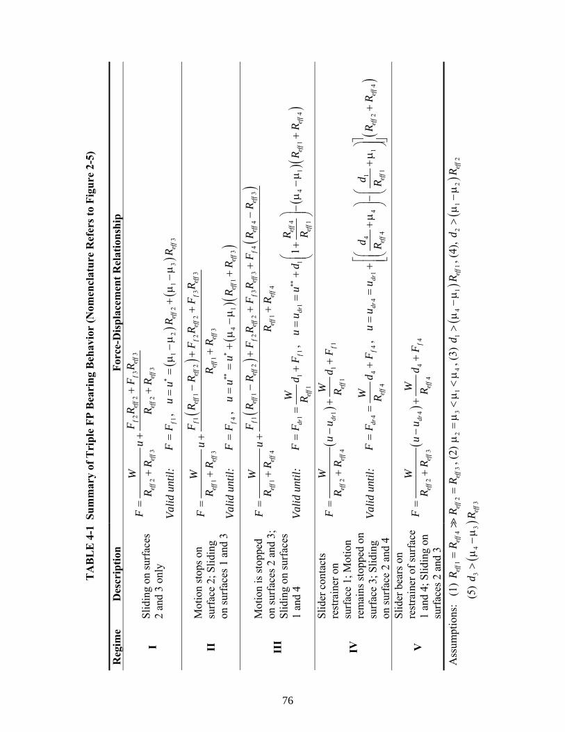
TA
BL
E 4
-1 S
umm
ary
of T
ripl
e FP
Bea
ring
Beh
avio
r (N
omen
clat
ure
Ref
ers t
o Fi
gure
2-5
) R
egim
e D
escr
iptio
n Fo
rce-
Dis
plac
emen
t Rel
atio
nshi
p 2
23
3
23
23
fef
ff
eff
eff
eff
eff
eff
FR
FR
WF
uR
RR
R+
=+
++
I
Slid
ing
on su
rfac
es
2 an
d 3
only
Va
lid u
ntil:
1f
FF
=,
(
)(
)1
22
13
3ef
fef
fu
uR
R∗
==
μ−
μ+
μ−
μ
()
11
22
23
3
13
13
fef
fef
ff
eff
fef
f
eff
eff
eff
eff
FR
RF
RF
RW
Fu
RR
RR
−+
+=
++
+
II
Mot
ion
stop
s on
surf
ace
2; S
lidin
g on
surf
aces
1 a
nd 3
Va
lid u
ntil:
4f
FF
=,
(
) ()
41
13
eff
eff
uu
uR
R∗∗
∗=
=+
μ−
μ+
()
()
11
22
23
34
43
14
14
fef
fef
ff
eff
fef
ff
eff
eff
eff
eff
eff
eff
FR
RF
RF
RF
RR
WF
uR
RR
R−
++
+−
=+
++
III
Mot
ion
is st
oppe
d on
surf
aces
2 a
nd 3
; Sl
idin
g on
surf
aces
1
and
4 Va
lid u
ntil:
1
11
1dr
fef
f
WF
Fd
FR
==
+,
(
) ()
41
14
11
41
1ef
fdr
eff
eff
eff
Ru
uu
dR
RR
∗∗⎛
⎞=
=+
+−
μ−
μ+
⎜⎟
⎜⎟
⎝⎠
()
11
12
41
drf
eff
eff
eff
WW
Fu
ud
FR
RR
=−
++
+
IV
Slid
er c
onta
cts
rest
rain
er o
n su
rfac
e 1;
Mot
ion
rem
ains
stop
ped
on
surf
ace
3; S
lidin
g on
surf
ace
2 an
d 4
Valid
unt
il:
44
44
drf
eff
WF
Fd
FR
==
+,
(
)4
14
14
12
44
1dr
dref
fef
fef
fef
f
dd
uu
uR
RR
R
⎡⎤
⎛⎞
⎛⎞
==
++
μ−
+μ
+⎢
⎥⎜
⎟⎜
⎟⎜
⎟⎜
⎟⎢
⎥⎝
⎠⎝
⎠⎣
⎦
V
Slid
er b
ears
on
rest
rain
er o
f sur
face
1
and
4; S
lidin
g on
su
rfac
es 2
and
3
()
44
42
34
drf
eff
eff
eff
WW
Fu
ud
FR
RR
=−
++
+
Ass
umpt
ions
: (1
) 1
42
3ef
fef
fef
fef
fR
RR
R=
=, (
2)
23
14
μ=
μ<
μ<
μ, (
3)
()
14
11
eff
dR
>μ
−μ
, (4)
, (
)2
12
2ef
fd
R>
μ−
μ
(5)
()
34
33
eff
dR
>μ
−μ
76

77
Sliding Regime V:umax > udr4
Total Displacement, u
Hor
izon
tal F
orce
Sliding Regime VSliding Regimes I - IV
Fdr4
Fdr1 - 2Ff1
Fdr4 - 2Ff4
udr4
WReff2 + Reff3
WReff1 + Reff3
WReff1 + Reff4
2Ff2
FIGURE 4-10 Force-Displacement Relationship During Sliding Regime V Shown in Relation to Sliding Regimes I-IV 4.7 Additional Comments 4.7.1 Behavior in the Case of Equal Friction Thus far, the behavior of the triple FP bearing has been described for the fully adaptive configuration of properties in which 2 3 1 4μ = μ < μ < μ . In this case there are multiple sliding phases and accordingly multiple changes in stiffness. However it can be shown that in simpler configurations the hysteretic behavior of the triple FP will collapse to that of the double FP or even the single FP. This is due to the fact that when friction is equal on two surfaces i and j , sliding starts simultaneously on each and theoretically they behave as a single surface having effective radius eff effi effjR R R= + . For the time being, these simpler configurations are the most likely to be implemented by practicing engineers. Consider a triple FP bearing in which 2 3 1 4μ = μ < μ = μ . For displacements u u∗< , sliding occurs only on surfaces 2 and 3 and the behavior is indistinguishable from sliding regime I of the standard configuration as described in section 4.2. The fundamental principles of operation must hold regardless of the relative values of the friction coefficients. Therefore, with increasing lateral force sliding will start on surface 1 when

78
1fF F= . However at this same point, 4fF F= and motion simultaneously starts on surface 4. By inspection, when 1 4μ = μ , equation (4-14) gives u u∗∗ ∗= . This means that the displacement range in which sliding regime II applies (from u∗ to u∗∗ ) goes to zero and the behavior immediately transitions from sliding on surfaces 2 and 3 to sliding on surfaces 1 and 4 (from sliding regime I to sliding regime III). The hysteretic behavior shown prior to any stiffening is shown in figure 4-11(b). It is rigid-bilinear with large unloading stiffness prior to the transition to sliding on surfaces 1 and 4. Finally, it should be noted that for 1 4μ = μ when the ratios 1 1effd R and 4 4effd R are the same, based on equation (4-28) 1 4dr dru u= and the slide plates contact the displacement restrainers on surfaces 1 and 4 simultaneously. The behavior further collapses in the case where all coefficients of friction are equal,
1 2 3 4μ = μ = μ = μ . Based on equations (4-7) and (4-14), it is clear that 0u u∗∗ ∗= = , meaning that sliding regime III governs instantaneously upon initiation of motion. This is further corroborated by examining equations (4-12) and (4-18); when the friction coefficients are equal 2 3 0u u= = indicating that there is no sliding on surfaces 2 and 3. In this case, prior to contacting the displacement restrainer there are no transitions in stiffness and the behavior is analogous to that of the single FP bearing. This is shown in figure 4-11(c). Similar to the previous case, when the ratios 1 1effd R and 4 4effd R are the same, based on equation (4-28) 1 4dr dru u= and the slide plates contact the displacement restrainers on surfaces 1 and 4 simultaneously. This last configuration is purely academic since it is in practice very difficult to achieve coefficients of friction that are exactly equal. If this were attempted, due to natural variability of material properties it would be uncertain whether 1 2μ > μ or whether
2 1μ > μ (and equally whether 4 3μ > μ or 3 4μ > μ ). Therefore it would not be possible with any certainty to predict whether in practice sliding will initiate on the outer concave surface or the recess of the slide plate. There are considerably different values of stiffness associated with each of these possibilities. In this case, the designer should just use the double FP bearing with concave surfaces of equal friction. 4.7.2 Applicability of Series Models One important result from the analysis of double FP bearings was that the overall behavior could be obtained by considering two single FP elements acting in series. This aspect of behavior has important implications for dynamic response history analysis. Even double FP bearings of unequal friction can be modeled with the existing analytical formulations used for single FP bearings in software used for analysis of seismically isolated structures. This means that these novel devices having unique behavior can be modeled without having to revise the current software. With this knowledge, it is tempting to assume that triple FP bearings can be modeled using three or four single FP elements connected in series. However, this is not the case. The behavior of the triple FP bearing is not that of a series arrangement of single FP bearings. This is due to the fact that the series model is incapable of reproducing the sliding-stopping-sliding behavior that the innermost sliding surfaces exhibit throughout

79
(a)
(b)
(c)
Fully Adaptive2 = 3 < 1 < 4
Displacement
Hor
izon
tal F
orce
Collapsed to Double2 = 3 < 1 = 4
Displacement
Hor
izon
tal F
orce
Collapsed to Single1 = 2 = 3 = 4
Displacement
Hor
izon
tal F
orce
[Assumed that Fmax < Fdr1 . . . Fdr4]
[Assumed that Fmax < Fdr1 . . . Fdr4]
WReff1+Reff4
WReff2+Reff3
WReff1+Reff4
FIGURE 4-11 Collapse of Adaptive Triple FP Bearing’s Behavior to Simpler Cases in Configurations of Equal Friction the course of motion. The result of this limitation is that the stiffness is under-predicted by the series model when sliding is occurring on the outer concave surfaces because it permits simultaneous sliding on both surfaces 1 and 2 (and 3 and 4). In actuality, simultaneous sliding cannot occur on surfaces 1 and 2 (and 3 and 4).
80
This has important implications in modeling triple FP bearings for dynamic analysis. It is shown elsewhere (Fenz and Constantinou, 2007b) that though the true behavior of the triple FP is not that of a series arrangement of single FP bearings, it is similar. Series models can be used to model the behavior provided that the input parameters are modified appropriately. This is beyond the scope of the current report and is discussed elsewhere in greater detail (Fenz and Constantinou, 2007b). 4.7.3 Actual Forces at which the Slider Contacts the Displacement Restrainer on Surfaces 2 and 3 For the fully adaptive configuration of triple FP bearing that has been described in this section, forces 2drF and 3drF are not actually the forces at which the slider contacts the displacement restrainer on surfaces 2 and 3. This is because motion on these surfaces is interrupted when sliding initiates on surfaces 1 and 4, respectively. Based on equation (4-23), the actual force at which the slider contacts the displacement restrainer of surface 2 is
1 2 12 2
1 2 1f dr
eff eff eff
d d dF W F F WR R R
⎛ ⎞= + + = +⎜ ⎟⎜ ⎟
⎝ ⎠ (4-32)
A similar expression can be derived based on equation (4-30) for surface 3. The forces
2drF and 3drF determined using equation (2-5) are the forces at which the slider would contact the displacement restrainer if sliding did not yet initiate on surfaces 1 and 4. They are not physically meaningful, but instead are needed for initial checking of the configuration and determining the sequencing of regimes. 4.7.4 Slider Offsets in Displacement-Controlled Tests In previous work on the double FP bearing, it was observed that the slider becomes offset within the bearing during displacement controlled harmonic tests when friction is different on the upper and lower surfaces (Fenz and Constantinou, 2006). This means at zero total displacement the individual displacements on each surface are equal and opposite rather than both zero. The same phenomenon occurs in the triple FP bearing. The offset occurs because the effective coefficient of friction (the normalized horizontal force at zero total displacement) is different from the coefficients of friction on the individual sliding surfaces (the normalized horizontal force at zero relative displacement). The magnitudes of the individual offsets are functions of the difference between the effective friction and the individual coefficients of friction, and therefore depend on both the configuration of the bearing and the amplitude of the motion. Explicit expressions for the individual offsets are not included in this report, however they can be determined by tracking the total force-displacement loops and monitoring the relative displacements as motion progresses. It is emphasized that slider offset is related to displacement controlled testing
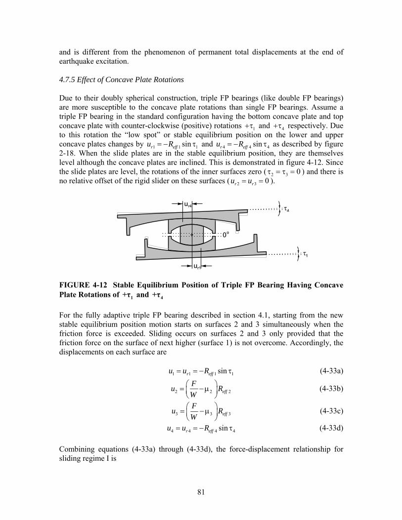
81
and is different from the phenomenon of permanent total displacements at the end of earthquake excitation. 4.7.5 Effect of Concave Plate Rotations Due to their doubly spherical construction, triple FP bearings (like double FP bearings) are more susceptible to the concave plate rotations than single FP bearings. Assume a triple FP bearing in the standard configuration having the bottom concave plate and top concave plate with counter-clockwise (positive) rotations 1+τ and 4+τ respectively. Due to this rotation the “low spot” or stable equilibrium position on the lower and upper concave plates changes by 1 1 1sinr effu R= − τ and 4 4 4sinr effu R= − τ as described by figure 2-18. When the slide plates are in the stable equilibrium position, they are themselves level although the concave plates are inclined. This is demonstrated in figure 4-12. Since the slide plates are level, the rotations of the inner surfaces zero ( 2 3 0τ = τ = ) and there is no relative offset of the rigid slider on these surfaces ( 2 3 0r ru u= = ).
FIGURE 4-12 Stable Equilibrium Position of Triple FP Bearing Having Concave Plate Rotations of 1+τ and 4+τ For the fully adaptive triple FP bearing described in section 4.1, starting from the new stable equilibrium position motion starts on surfaces 2 and 3 simultaneously when the friction force is exceeded. Sliding occurs on surfaces 2 and 3 only provided that the friction force on the surface of next higher (surface 1) is not overcome. Accordingly, the displacements on each surface are 1 1 1 1sinr effu u R= = − τ (4-33a)
2 2 2effFu RW
⎛ ⎞= − μ⎜ ⎟⎝ ⎠
(4-33b)
3 3 3effFu RW
⎛ ⎞= − μ⎜ ⎟⎝ ⎠
(4-33c)
4 4 4 4sinr effu u R= = − τ (4-33d) Combining equations (4-33a) through (4-33d), the force-displacement relationship for sliding regime I is
82
( ) 2 2 3 31 4
2 3 2 3
f eff f effr r
eff eff eff eff
F R F RWF u u uR R R R
+= − − +
+ + (4-34)
Equation (4-34) demonstrates that provided 1fF F≤ , sliding occurs on the innermost surfaces with no effect on the strength or stiffness caused by the rotation. The only effect of the rotation during sliding regime I is that the bearing now oscillates about the inclined stable equilibrium position at 1 4r ru u u= + . Since the rotation has no effect on friction, sliding on surface 1 (the surface of next higher friction) starts when the horizontal force is 1fF F= - the same as in the level configuration. However, due to the rotation, the sliding motion on this surface starts from the offset stable equilibrium position at 1 1ru u= . Since the stiffness exhibited by this surface remains the same, starting from this offset position will result in a vertical translation of the decomposed hysteresis loop. After motion starts on surface 1, but prior to motion starting on surface 4, the individual displacements on each surface are
1 1 1 1eff rFu R uW
⎛ ⎞= − μ +⎜ ⎟⎝ ⎠
(4-35a)
( )2 1 2 2effu R= μ − μ (4-35b)
3 3 3effFu RW
⎛ ⎞= − μ⎜ ⎟⎝ ⎠
(4-35c)
4 4 4 4sinr effu u R= = − τ (4-35d) Combining equations (4-35a) through (4-35d), the force-displacement relationship for sliding regime II is
( ) ( )1 1 2 2 2 3 31 4
1 3 1 3
f eff eff f eff f effr r
eff eff eff eff
F R R F R F RWF u u uR R R R
− + += − − +
+ + (4-36)
Comparing equations (4-13) and (4-36), it is clear that the behavior is similar in the level and inclined configurations except that the stable equilibrium position changes from
0u = to 1 4r ru u u= + . As a result, there is a vertical shift in the hysteresis loops (up or down depending on the magnitude and direction of the rotation) as well. Similarly, when the horizontal force exceeds the friction force on surface 4, sliding stops on surface 3 and starts on surface 4 with force-displacement relationship
( ) ( ) ( )1 1 2 2 2 3 3 4 4 31 4
1 4 1 4
f eff eff f eff f eff f eff effr r
eff eff eff eff
F R R F R F R F R RWF u u uR R R R
− + + + −= − − +
+ +
(4-37)

83
Again, when equations (4-19) and (4-37) are compared it is clear that the effect of the rotation for sliding regime III will be a vertical shift due to the change in the stable equilibrium position. The behavior for sliding regime IV is described here assuming that the slider still makes contact with the restrainer of surface 1 prior to surface 4. However due to the rotation, it is possible in certain configurations that the sequencing can be reversed from what would be expected if the concave plates were installed without rotation. For example, in the standard fully adaptive configuration a level bearing will have the slider contact surface 1 prior to surface 4. However, for certain combinations of rotations, it is possible that the slider may contact the displacement restrainer of surface 4 prior to surface 1 in one direction of motion. The order in which the displacement restrainers are contacted is determined by comparing the relative values of dri iF W± τ for surfaces 1 and 4 in each direction of motion. For example, if surface 1 has a positive (counter-clockwise) rotation and surface 4 has a negative (clockwise) rotation, then the order in which the surfaces are contacted are determined by comparing
1 1 1 11
dr feff
WF d F WR
= + + τ (4-38)
and
4 4 4 44
dr feff
WF d F WR
= + − τ (4-39)
for motion in the positive direction. The minimum of equations (4-38) and (4-39) determines upon which surface the displacement restrainer is first contacted. For motion in the negative direction, the order is determined by comparing
1 1 1 11
dr feff
WF d F WR
= + − τ (4-40)
and
4 4 4 44
dr feff
WF d F WR
= + + τ (4-41)
The minimum of equations (4-40) and (4-41) determines upon which surface the displacement restrainer is first contacted. Assuming that the slider still makes first contact with the restrainer of surface 1, the total displacement at which this occurs is determined by solving equation (4-37) for the displacement when 1drF F= as determined by equation(4-38). It is found that

84
( )( ) ( )4**1 1 4 1 1 4 1 4 1 1 4
1
1 effdr eff eff r r eff eff
eff
Ru u d R R u u R R
R⎛ ⎞
= + + − μ − μ + + + + τ +⎜ ⎟⎜ ⎟⎝ ⎠
(4-42)
where u∗∗ is given by equation (4-14). Equation (4-42) is essentially (4-21) with slight modification as a result of the rotation. It reflects the asymmetry in the force-total displacement loop that results from the displacement capacity of surface 1 being 1 1rd u+ in one direction and 1 1rd u− in the other. After the slider contacts the displacement restrainer on surface 1, the force displacement relationship becomes
( )2 2 4 3 3 4 4 21 4 1
2 4 2 4 2 4 1
f eff f f eff f eff effr r
eff eff eff eff eff eff eff
F R F F R F R Ru u u dF W WR R R R R R R
− − +− −= + +
+ + +
(4-43a)
4 4
2 4
efflevel
eff eff
RF F W
R Rτ
= ++
(4-43b)
In comparison to the level configuration, this demonstrates that there is a vertical shift of the total hysteresis loop by an amount ( ) ( )4 4 2 4eff eff effR W R Rτ + . For sliding regime V there will be asymmetry in the force-total displacement loop due to the fact that the displacement capacity on surface 4 becomes 4 4rd u+ in one direction and
4 4rd u− in the other direction. The slider will meet the displacement restrainer when 4 4drF F W= + τ . The displacement when this occurs is
( ) ( )4 14 1 4 1 2 4 4 4 2 4
4 1dr dr eff eff r eff eff
eff eff
d du u R R u R RR R
⎡ ⎤⎛ ⎞ ⎛ ⎞= + + μ − + μ + + + τ +⎢ ⎥⎜ ⎟ ⎜ ⎟⎜ ⎟ ⎜ ⎟⎢ ⎥⎝ ⎠ ⎝ ⎠⎣ ⎦
(4-44)
where 1dru is that of the level configuration as given by equation (4-21). Comparing equations (4-44) and (4-28), it can be seen that ( )4, 4, 4 4 2 4dr level dr rotated r eff effu u u R R= + + τ + , which again results in asymmetry of the hysteresis loop. After contact is made with the displacement restrainer of surface 4, motion continues on surfaces 2 and 3 with force-displacement relationship given by
( )4 4 4 42 4 4
dr feff eff eff
W WF u u d F WR R R
= − + + + τ+
(4-45)
where 4dru is given by equation(4-44).

85
4.8 Behavior of the Modified Single FP Bearing
The modified single FP bearing is similar in construction to the conventional FP bearing, but with an intermediate slide plate. It is essentially a simpler adaptation of the triple FP bearing. Therefore, its behavior is less complex than that of the triple FP bearing, but exhibits the same characteristics of motion. In the standard configuration of 1 2eff effR R and 1 2μ > μ (with reference to figure 2-7), the force-displacement relationship of the modified single FP is composed of three sliding regimes: (I) initial sliding only on surface 2 with high stiffness and low friction, (II) sliding only on surface 1 with a decrease in stiffness and an increase in friction, and (III) stiffening as the slide plate contacts the displacement restrainer of surface 1 and sliding on surface 2 resumes. This configuration will readily activate and re-center well in minor events, provide sufficient flexibility and damping for more severe shaking and then stiffen substantially before the maximum displacement capacity of the bearing is achieved. Upon application of horizontal force F , motion will initiate on surface 2, the surface of least friction when 2fF F= . Since sliding occurs on surface 2 only, the force-displacement relationship follows from the equilibrium equations of the traditional FP bearing (Zayas et al., 1987) and is given by
22
feff
WF u FR
= + (4-46)
If the direction of motion reverses prior to the initiation of motion on surface 1, the bearing will unload by 22 fF and sliding will continue only on surface 2. As shown in figure 4-13(a), the hysteretic behavior is identical to that of the conventional FP bearing. With increasing applied lateral force, the friction force on surface 1 is overcome at total displacement u∗ given by ( )1 2 2effu R∗ = μ − μ (4-47) Equation (4-47) is determined by solving equation (4-46) for the displacement when
1fF F= . The displaced shape after motion has initiated on surface 1 and free body diagrams of the various parts of the bearing in the displaced configuration are shown in figure 4-14. The rotation of the slide plate with respect to the outer concave plate is 1θ and the rotation of the articulated slider with respect to the slide plate is 2θ . When the angles are defined in this way, the relative displacements 1u and 2u are 1 1 1sineffu R= θ (4-48a) 2 2 2sineffu R= θ (4-48b)

86
Total Dispalcement, u
(a)
Hor
izon
tal F
orce
Sliding Regime III: u* < umax < udr1
Total Displacement, u
(c)
Hor
izon
tal F
orce
Sliding Regime IIISliding Regimes I - II
Total Dispalcement, u
(b)
Hor
izon
tal F
orce
Sliding Regime IISliding Regime I
Ff2
2Ff2
W Reff2
Sliding Regime I:umax < u* W
Reff2
Sliding Regime II:u* < umax < udr1 2Ff2
2Ff1
W Reff1
W Reff1
W Reff2
Fdr1
udr1
Fdr1 - 2Ff1
WReff2
WReff2
2Ff2
u*
2u*
Ff1
FIGURE 4-13 Force-Displacement Relationship of the Modified Single FP Bearing (a) for Sliding Regime I, (b) for Sliding Regime II and (c) for Sliding Regime III

87
FIGURE 4-14 Displaced Shape (a) and Free Body Diagrams (b) of the Modified Single FP Bearing During Sliding Regime II

88
From FBD III of figure 4-14(b), the equilibrium equations of the traditional FP bearing are obtained leading to the following force-displacement relationship for surface 1:
1 11
feff
WF u FR
= + (4-49)
The equations of equilibrium for surface 2 reflect that the articulated slider is now inclined at an angle 1 2θ + θ with respect to the horizontal due to the rotation of the slide plate. From FBD II of figure 4-14(b) the equilibrium equations in the vertical and horizontal directions are ( ) ( )1 1 1 1 2 1 2 2 1 2cos sin cos sin 0f fS F S Fθ − θ − θ + θ + θ + θ = (4-50a)
( ) ( )1 1 1 1 2 1 2 2 1 2sin cos sin cos 0f fS F S F− θ − θ + θ + θ + θ + θ = (4-50b) The first two terms of the left hand side of equation (4-50a) are equal to the vertical load W and the first two terms of the left hand side of equation (4-50b) are equal to the negative of the horizontal force F− . Using equations (4-48) and (4-50) and the assumptions that the individual angles 1θ and 2θ are small so that 1 2cos cos 1θ ≈ θ ≈ and
1 2sin sin 0θ × θ ≈ , the force-displacement relationship for surface 2 is
1 22
1 2f
eff eff
u uF W FR R
⎛ ⎞= + +⎜ ⎟⎜ ⎟
⎝ ⎠ (4-51)
Substituting equation (4-49) into equation (4-51), the relative displacement of the slider on surface 2 throughout sliding regime II is ( )2 1 2 2effu R u∗= μ − μ = (4-52) Equation (4-52) demonstrates that the relative displacement on surface 2 is constant with magnitude equal to the value of 2u when sliding initiates on surface 1. This means that the instant motion starts on surface 1 it stops on surface 2 and remains stopped. This is identical to the behavior obtained for the triple FP bearing, which is expected due to the similarity of their construction. The force-total displacement relationship for u u∗> (but prior to contacting the displacement restrainer on surface 1) is determined by combining equations (4-49) and (4-52) to obtain
( ) 11
feff
WF u u FR
∗= − + (4-53)
Upon reversal of motion, the bearing will unload by 22 fF and motion will initiate on surface 2. Motion continues on surface 2 over a distance *2u until the bearing has unloaded by 12 fF , at which point motion will resume on surface 1 and stop on surface 2. The force-displacement behavior for this sliding regime is shown in figure 4-13(b).

89
Sliding occurs on surface 1 only until the slide plate starts to bear on the displacement restrainer. At the instant the slide plate contacts the displacement restrainer on surface 1 the horizontal force is
1 1 11
dr feff
WF F d FR
= = + (4-54)
and the total displacement is *
1 1dru u d u= = + (4-55) Equation (4-55) can be obtained by solving equation (4-53) for the displacement when
1drF F= or by simple consideration that at the instant contact is made with the displacement restrainer 1 1u d= and 2u u∗= . With the slider bearing on the displacement restrainer of surface 1, sliding can occur only on surface 2 until the total displacement capacity of the bearing is achieved. The force-total displacement relationship for this sliding regime ( )1dru u> is therefore
( )1 1 12 1
dr feff eff
W WF u u d FR R
= − + + (4-56)
Upon reversal of motion, the bearing unloads by 22 fF and sliding occurs on surface 2. Sliding resumes on surface 1 and stops on surface 2 when the bearing unloads to
1 12dr fF F− . This is shown in figure 4-13(c). The equations governing the force-displacement relationship of modified single FP bearings for all three sliding regimes are summarized in table 4-2. Similar to the other multi-spherical sliding bearings, the force-displacement behavior collapses and simplifies in cases when the friction coefficients are the same on both surfaces. For the modified single FP bearing when the friction coefficients 1μ and 2μ are the same, 0u∗ = and the behavior collapses to that of a single FP bearing with effective radius of curvature 2effR . Again however, this is simply an academic point as there is no practical advantage offered by the modified single FP bearing with 1 2μ = μ over a traditional single FP bearing or double FP bearing having surfaces of equal friction.
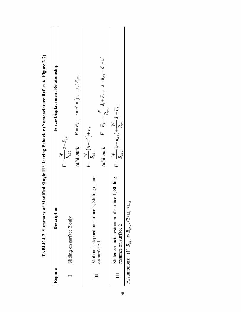
T
AB
LE
4-2
Sum
mar
y of
Mod
ified
Sin
gle
FP B
eari
ng B
ehav
ior
(Nom
encl
atur
e R
efer
s to
Figu
re 2
-7)
Reg
ime
Des
crip
tion
Forc
e-D
ispl
acem
ent R
elat
ions
hip
22
fef
f
WF
uF
R=
+
I Sl
idin
g on
surf
ace
2 on
ly
Valid
unt
il:
1fF
F=
, (
)1
22
eff
uu
R∗
==
μ−
μ
()
11
fef
f
WF
uu
FR
∗=
−+
II
Mot
ion
is st
oppe
d on
surf
ace
2; S
lidin
g oc
curs
on
surf
ace
1 Va
lid u
ntil:
1
11
1dr
fef
f
WF
Fd
FR
==
+,
11
dru
ud
u∗=
=+
III
Slid
er c
onta
cts r
estra
iner
of s
urfa
ce 1
; Slid
ing
resu
mes
on
surf
ace
2 (
)1
11
21
drf
eff
eff
WW
Fu
ud
FR
R=
−+
+
Ass
umpt
ions
: (1
) 1
2ef
fef
fR
R, (
2)
12
μ>
μ
90

91
SECTION 5 EXPERIMENTAL VALIDATION OF MECHANICAL BEHAVIOR
5.1 Introduction This section describes an experimental program of characterization testing that was performed to assess the validity of the proposed theoretical behavior. It is largely a compilation of the results first presented in Fenz and Constantinou (2006, 2007c). The three variations of multi-spherical sliding bearing were tested in many different configurations to validate the theory over a broad spectrum of conditions. The primary objective was to measure the force-displacement behavior for slow speed displacement-controlled tests of various amplitudes in order to verify the analytical model and principles of operation. Slow speed tests were favored since hysteresis loops obtained under nearly quasi-static test conditions exhibited clear transitions in stiffness and permitted more accurate comparison to the proposed analytical models. A limited number of tests were also carried out at high speed to explore the behavior under more realistic dynamic conditions and evaluate any effects of impact when the slider contacts the displacement restrainer. The experimental results generally are in good agreement with the analytical models from both a quantitative and more importantly a qualitative standpoint. The later statement means that the sequencing of sliding regimes and the starting/stopping of sliding on the various surfaces is consistent with the behavior that is predicted based on first principles. Demonstrating the predictability of the behavior contributes towards showing that these devices combine the performance benefits of hybrid isolation systems with the reliability of currently used technologies. 5.2 Description of Test Specimens Figures 5-1 through 5-3 show the various reduced-scale specimens that were tested as part of the experimental program. Each was tested with different combinations of displacement capacities and coefficients of friction. To change the displacement capacities of the outer concave surfaces, a urethane ring (hardness 62D) was machined that could be easily inserted and removed. As shown in figure 5-4, the ring could be press fit into the outer concave plate to reduce the displacement capacity of this surface by 25 mm. Frictional conditions were varied by lubricating the various sliding materials with a medium weight silicone grease. Compared to the dry or un-lubricated condition, when lubricated these materials exhibited substantially lower frictional properties. All configurations tested are summarized in figure 5-5 and table 5-1.
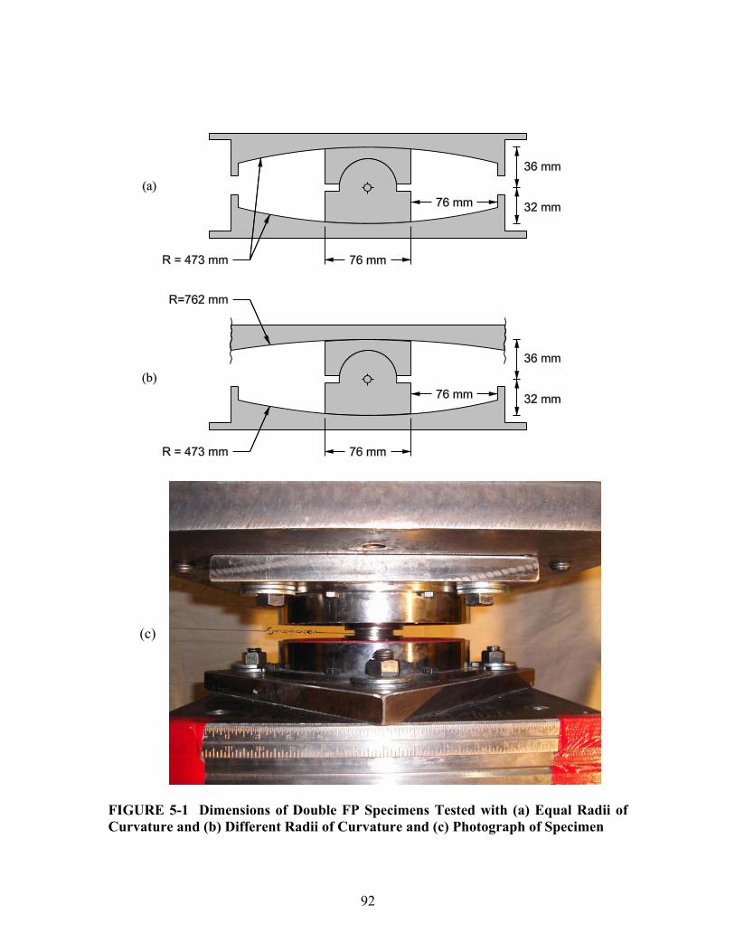
92
(c)
FIGURE 5-1 Dimensions of Double FP Specimens Tested with (a) Equal Radii of Curvature and (b) Different Radii of Curvature and (c) Photograph of Specimen

93
(a)
(b) FIGURE 5-2 Dimensions (a) and Photograph (b) of Triple FP Bearing Tested (Shown Separated to Better Reveal Internal Construction)

94
(a)
(b) FIGURE 5-3 Dimensions (a) and Photograph (b) of Modified Single FP Bearing Tested (Shown Separated to Better Reveal Internal Construction)

95
FIGURE 5-4 Sketch of Urethane Ring Inserted to Reduce the Displacement Capacity of the Concave Plate The double FP specimen was assembled using stainless steel concave plates having a diameter of 230 mm and radius of curvature of 473 mm. Additionally, two configurations were tested in which a larger diameter concave plate having radius of curvature of 762 mm was used. The articulated slider had a height of 68 mm and was coated with a non-metallic sliding material denoted Material D. Testing was performed with both surfaces of the slider dry to achieve nearly equal coefficients of friction as well as with one surface lubricated to achieve substantially different coefficients of friction. To achieve effective lubrication, the radius of curvature of the slider at its upper and lower surfaces was manufactured larger than the radius of the mating concave plate. This resulted in bearing only over an annular area around the perimeter of the slider, thus creating a pocket which effectively contained the lubricant. After testing several configurations in which the displacement restrainer was not contacted (configurations 1-4), the urethane ring was inserted as shown in figure 5-5(a) to create surfaces of different displacement capacity (configurations 5-7) and further explore the behavior after contact. The triple FP specimen employed two identical 230 mm concave plates as were used in the double FP specimen. It was tested without the urethane ring, with the urethane ring in the top concave plate and with the urethane ring in the bottom concave plate as shown in figure 5-5(b). Though the standard configuration of triple FP bearing is outer concave surfaces of equal displacement capacity, configurations with different displacement capacities were tested to evaluate the validity of the analytical model for more general cases. Two different non-metallic sliding materials denoted Material A and Material B were used on the sliding interfaces. Each surface of the inner rigid slider was coated with Material A that had been lubricated, the upper slide plate was coated with dry Material A and the lower slide plate with dry Material B. When dry, the coefficient of friction of Material A is less than that of Material B. Lubrication combined with the increased pressure due to the smaller contact area ensured that the coefficients of friction of the rigid slider would be lower than those of the slide plates, providing 2 3 1 4μ = μ < μ < μ . At

96
each sliding interface, the radius of curvature of the slide plate was manufactured larger than the mating stainless steel surface. There was bearing over an annular area on the perimeter of each slide plate creating a pocket to contain the lubricant.
FIGURE 5-5 Summary of the Various Configurations of Multi-Spherical Sliding Bearings Tested

97
TABLE 5-1 Summary of Properties of the Various Configurations Tested
Configuration Nominal
Coefficients of Friction
Nominal Displacement
Capacities
Effective Radii of Curvature ( )i iR h−
1 76 mmd = 1 441 mmeffR = Double 1 1 2μ ≈ μ
2 76 mmd = 2 437 mmeffR =
1 76 mmd = 1 441 mmeffR = Double 2 1 2μ ≈ μ
2 -d = 2 726 mmeffR =
1 76 mmd = 1 441 mmeffR = Double 3 1 2μ < μ
2 76 mmd = 2 437 mmeffR =
1 76 mmd = 1 441 mmeffR = Double 4 1 2μ < μ
2 -d = 2 726 mmeffR =
1 51 mmd = 1 441 mmeffR = Double 5 1 2μ ≈ μ
2 76 mmd = 2 437 mmeffR =
1 76 mmd = 1 441 mmeffR = Double 6 1 2μ < μ
2 51 mmd = 2 437 mmeffR =
1 51 mmd = 1 441 mmeffR = Double 7 1 2μ < μ
2 76 mmd = 2 437 mmeffR =
2 3 19 mmd d= = 2 3 53 mmeff effR R= =
1 64 mmd = 1 4 435 mmeff effR R= =Triple 1 2 3 1 4μ = μ < μ < μ
4 64 mmd =
2 3 19 mmd d= = 2 3 53 mmeff effR R= =
1 39 mmd = 1 4 435 mmeff effR R= =Triple 2 2 3 1 4μ = μ < μ < μ
4 64 mmd =
2 3 19 mmd d= = 2 3 53 mmeff effR R= =
1 64 mmd = 1 4 435 mmeff effR R= =Triple 3 2 3 1 4μ = μ < μ < μ
4 39 mmd =
1 64 mmd = 1 455 mmeffR = Modified single 1 1 2μ > μ
2 25 mmd = 2 73 mmeffR =
1 39 mmd = 1 455 mmeffR = Modified single 2 1 2μ > μ
2 25 mmd = 2 73 mmeffR =
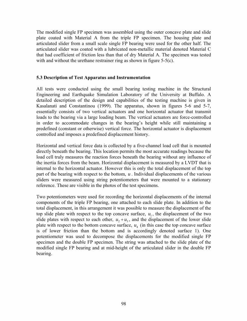
98
The modified single FP specimen was assembled using the outer concave plate and slide plate coated with Material A from the triple FP specimen. The housing plate and articulated slider from a small scale single FP bearing were used for the other half. The articulated slider was coated with a lubricated non-metallic material denoted Material C that had coefficient of friction less than that of dry Material A. The specimen was tested with and without the urethane restrainer ring as shown in figure 5-5(c). 5.3 Description of Test Apparatus and Instrumentation All tests were conducted using the small bearing testing machine in the Structural Engineering and Earthquake Simulation Laboratory of the University at Buffalo. A detailed description of the design and capabilities of the testing machine is given in Kasalanati and Constantinou (1999). The apparatus, shown in figures 5-6 and 5-7, essentially consists of two vertical actuators and one horizontal actuator that transmit loads to the bearing via a large loading beam. The vertical actuators are force-controlled in order to accommodate changes in the bearing’s height while still maintaining a predefined (constant or otherwise) vertical force. The horizontal actuator is displacement controlled and imposes a predefined displacement history. Horizontal and vertical force data is collected by a five-channel load cell that is mounted directly beneath the bearing. This location permits the most accurate readings because the load cell truly measures the reaction forces beneath the bearing without any influence of the inertia forces from the beam. Horizontal displacement is measured by a LVDT that is internal to the horizontal actuator. However this is only the total displacement of the top part of the bearing with respect to the bottom, u . Individual displacements of the various sliders were measured using string potentiometers that were mounted to a stationary reference. These are visible in the photos of the test specimens. Two potentiometers were used for recording the horizontal displacements of the internal components of the triple FP bearing, one attached to each slide plate. In addition to the total displacement, in this arrangement it was possible to measure the displacement of the top slide plate with respect to the top concave surface, 1u , the displacement of the two slide plates with respect to each other, 2 3u u+ , and the displacement of the lower slide plate with respect to the bottom concave surface, 4u (in this case the top concave surface is of lower friction than the bottom and is accordingly denoted surface 1). One potentiometer was used to decompose the displacements for the modified single FP specimen and the double FP specimen. The string was attached to the slide plate of the modified single FP bearing and at mid-height of the articulated slider in the double FP bearing.

99
Horizontal Actuator
LoadingBeam Load Cell
Bearing Specimen
Vertical Actuators
Stability Bracing
FIGURE 5-6 Apparatus Used for Experimental Testing
FIGURE 5-7 Dimensioned Drawing of Test Apparatus – Stability Bracing not Shown (Reproduced from Kasalanati and Constantinou, 1999)
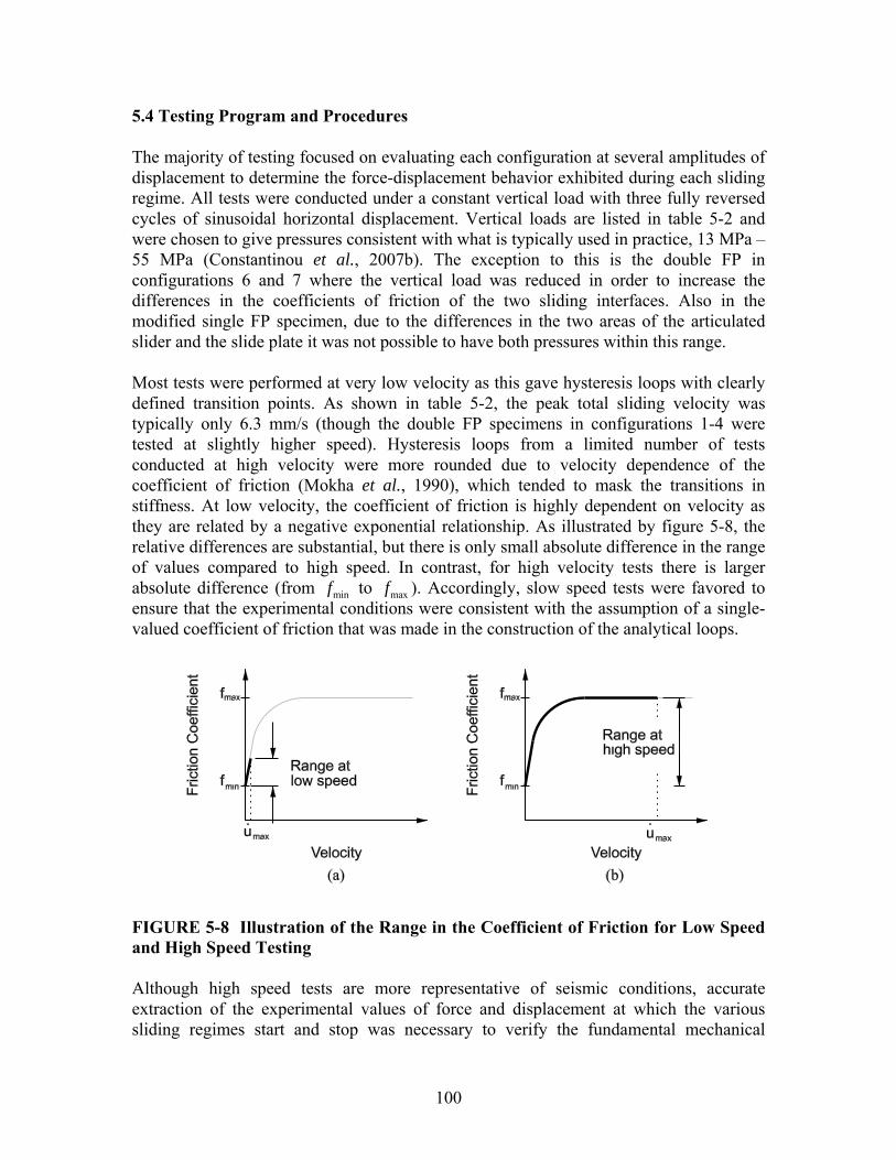
100
5.4 Testing Program and Procedures The majority of testing focused on evaluating each configuration at several amplitudes of displacement to determine the force-displacement behavior exhibited during each sliding regime. All tests were conducted under a constant vertical load with three fully reversed cycles of sinusoidal horizontal displacement. Vertical loads are listed in table 5-2 and were chosen to give pressures consistent with what is typically used in practice, 13 MPa – 55 MPa (Constantinou et al., 2007b). The exception to this is the double FP in configurations 6 and 7 where the vertical load was reduced in order to increase the differences in the coefficients of friction of the two sliding interfaces. Also in the modified single FP specimen, due to the differences in the two areas of the articulated slider and the slide plate it was not possible to have both pressures within this range. Most tests were performed at very low velocity as this gave hysteresis loops with clearly defined transition points. As shown in table 5-2, the peak total sliding velocity was typically only 6.3 mm/s (though the double FP specimens in configurations 1-4 were tested at slightly higher speed). Hysteresis loops from a limited number of tests conducted at high velocity were more rounded due to velocity dependence of the coefficient of friction (Mokha et al., 1990), which tended to mask the transitions in stiffness. At low velocity, the coefficient of friction is highly dependent on velocity as they are related by a negative exponential relationship. As illustrated by figure 5-8, the relative differences are substantial, but there is only small absolute difference in the range of values compared to high speed. In contrast, for high velocity tests there is larger absolute difference (from minf to maxf ). Accordingly, slow speed tests were favored to ensure that the experimental conditions were consistent with the assumption of a single-valued coefficient of friction that was made in the construction of the analytical loops.
FIGURE 5-8 Illustration of the Range in the Coefficient of Friction for Low Speed and High Speed Testing Although high speed tests are more representative of seismic conditions, accurate extraction of the experimental values of force and displacement at which the various sliding regimes start and stop was necessary to verify the fundamental mechanical
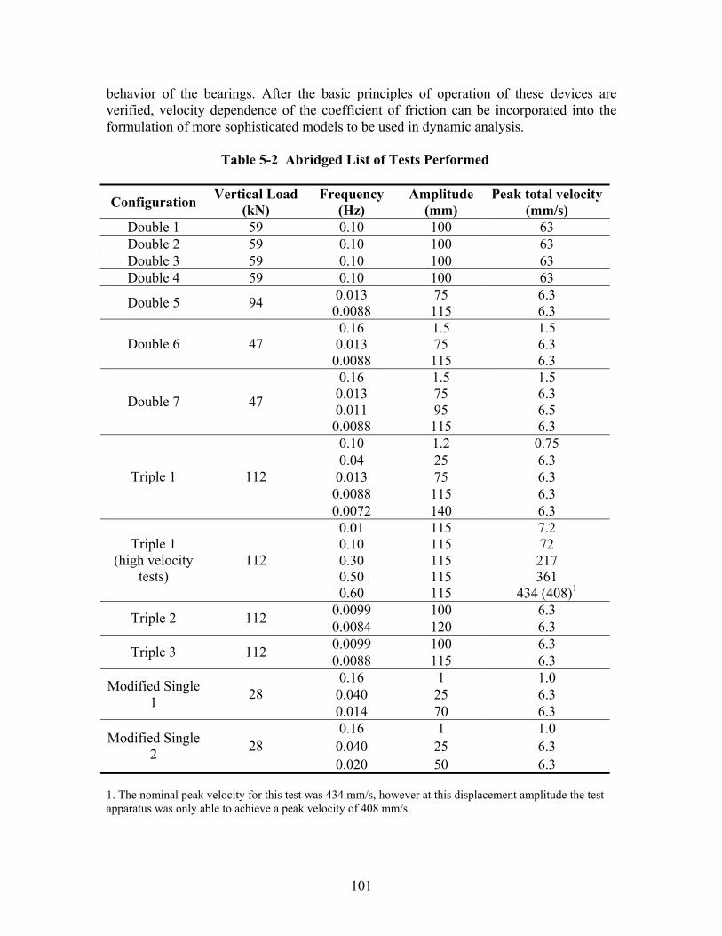
101
behavior of the bearings. After the basic principles of operation of these devices are verified, velocity dependence of the coefficient of friction can be incorporated into the formulation of more sophisticated models to be used in dynamic analysis.
Table 5-2 Abridged List of Tests Performed
Configuration Vertical Load(kN)
Frequency (Hz)
Amplitude (mm)
Peak total velocity (mm/s)
Double 1 59 0.10 100 63 Double 2 59 0.10 100 63 Double 3 59 0.10 100 63 Double 4 59 0.10 100 63
0.013 75 6.3 Double 5 94 0.0088 115 6.3 0.16 1.5 1.5 0.013 75 6.3 Double 6 47 0.0088 115 6.3 0.16 1.5 1.5 0.013 75 6.3 0.011 95 6.5 Double 7 47
0.0088 115 6.3 0.10 1.2 0.75 0.04 25 6.3 0.013 75 6.3 0.0088 115 6.3
Triple 1 112
0.0072 140 6.3 0.01 115 7.2 0.10 115 72 0.30 115 217 0.50 115 361
Triple 1 (high velocity
tests) 112
0.60 115 434 (408)1
0.0099 100 6.3 Triple 2 112 0.0084 120 6.3 0.0099 100 6.3 Triple 3 112 0.0088 115 6.3 0.16 1 1.0 0.040 25 6.3 Modified Single
1 28 0.014 70 6.3 0.16 1 1.0 0.040 25 6.3 Modified Single
2 28 0.020 50 6.3
1. The nominal peak velocity for this test was 434 mm/s, however at this displacement amplitude the test apparatus was only able to achieve a peak velocity of 408 mm/s.
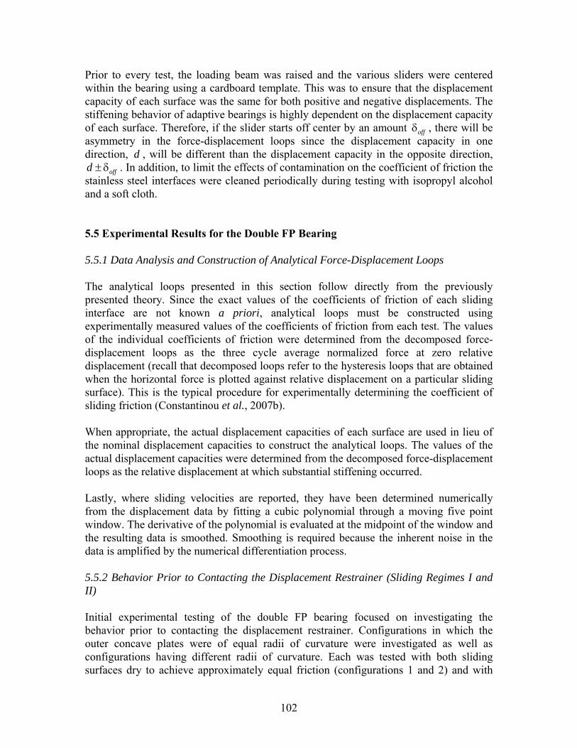
102
Prior to every test, the loading beam was raised and the various sliders were centered within the bearing using a cardboard template. This was to ensure that the displacement capacity of each surface was the same for both positive and negative displacements. The stiffening behavior of adaptive bearings is highly dependent on the displacement capacity of each surface. Therefore, if the slider starts off center by an amount offδ , there will be asymmetry in the force-displacement loops since the displacement capacity in one direction, d , will be different than the displacement capacity in the opposite direction,
offd ± δ . In addition, to limit the effects of contamination on the coefficient of friction the stainless steel interfaces were cleaned periodically during testing with isopropyl alcohol and a soft cloth. 5.5 Experimental Results for the Double FP Bearing 5.5.1 Data Analysis and Construction of Analytical Force-Displacement Loops The analytical loops presented in this section follow directly from the previously presented theory. Since the exact values of the coefficients of friction of each sliding interface are not known a priori, analytical loops must be constructed using experimentally measured values of the coefficients of friction from each test. The values of the individual coefficients of friction were determined from the decomposed force-displacement loops as the three cycle average normalized force at zero relative displacement (recall that decomposed loops refer to the hysteresis loops that are obtained when the horizontal force is plotted against relative displacement on a particular sliding surface). This is the typical procedure for experimentally determining the coefficient of sliding friction (Constantinou et al., 2007b). When appropriate, the actual displacement capacities of each surface are used in lieu of the nominal displacement capacities to construct the analytical loops. The values of the actual displacement capacities were determined from the decomposed force-displacement loops as the relative displacement at which substantial stiffening occurred. Lastly, where sliding velocities are reported, they have been determined numerically from the displacement data by fitting a cubic polynomial through a moving five point window. The derivative of the polynomial is evaluated at the midpoint of the window and the resulting data is smoothed. Smoothing is required because the inherent noise in the data is amplified by the numerical differentiation process. 5.5.2 Behavior Prior to Contacting the Displacement Restrainer (Sliding Regimes I and II) Initial experimental testing of the double FP bearing focused on investigating the behavior prior to contacting the displacement restrainer. Configurations in which the outer concave plates were of equal radii of curvature were investigated as well as configurations having different radii of curvature. Each was tested with both sliding surfaces dry to achieve approximately equal friction (configurations 1 and 2) and with
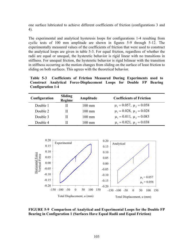
103
one surface lubricated to achieve different coefficients of friction (configurations 3 and 4). The experimental and analytical hysteresis loops for configurations 1-4 resulting from cyclic tests of 100 mm amplitude are shown in figures 5-9 through 5-12. The experimentally measured values of the coefficients of friction that were used to construct the analytical loops are given in table 5-3. For equal friction, regardless of whether the radii are equal or unequal, the hysteretic behavior is rigid linear with no transitions in stiffness. For unequal friction, the hysteretic behavior is rigid bilinear with the transition in stiffness occurring as the motion changes from sliding on the surface of least friction to sliding on both surfaces. This agrees with the theoretical behavior. Table 5-3 Coefficients of Friction Measured During Experiments used to Construct Analytical Force-Displacement Loops for Double FP Bearing Configuration 1-4
Configuration Sliding Regime Amplitude Coefficients of Friction
Double 1 II 100 mm 1 20.057, 0.058μ = μ = Double 2 II 100 mm 1 20.028, 0.028μ = μ = Double 3 II 100 mm 1 20.011, 0.083μ = μ = Double 4 II 100 mm 1 20.021, 0.038μ = μ =
Experimental
Total Displacement, u (mm)
-150 -100 -50 0 50 100 150
Hor
izon
tal F
orce
Ver
tical
For
ce
-0.20
-0.15
-0.10
-0.05
0.00
0.05
0.10
0.15
0.20Analytical
Total Displacement, u (mm)
-150 -100 -50 0 50 100 150-0.20
-0.15
-0.10
-0.05
0.00
0.05
0.10
0.15
0.20
1 = 0.057
2 = 0.058
FIGURE 5-9 Comparison of Analytical and Experimental Loops for the Double FP Bearing in Configuration 1 (Surfaces Have Equal Radii and Equal Friction)
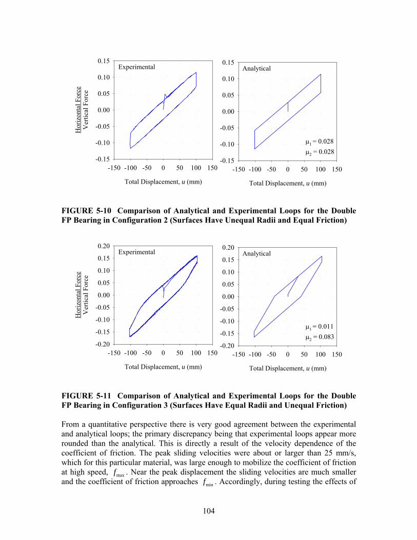
104
Experimental
Total Displacement, u (mm)
-150 -100 -50 0 50 100 150
Hor
izon
tal F
orce
Ver
tical
For
ce
-0.15
-0.10
-0.05
0.00
0.05
0.10
0.15Analytical
Total Displacement, u (mm)
-150 -100 -50 0 50 100 150-0.15
-0.10
-0.05
0.00
0.05
0.10
0.15
1 = 0.028
2 = 0.028
FIGURE 5-10 Comparison of Analytical and Experimental Loops for the Double FP Bearing in Configuration 2 (Surfaces Have Unequal Radii and Equal Friction)
Experimental
Total Displacement, u (mm)
-150 -100 -50 0 50 100 150
Hor
izon
tal F
orce
Ver
tical
For
ce
-0.20
-0.15
-0.10
-0.05
0.00
0.05
0.10
0.15
0.20Analytical
Total Displacement, u (mm)
-150 -100 -50 0 50 100 150-0.20
-0.15
-0.10
-0.05
0.00
0.05
0.10
0.15
0.20
1 = 0.011
2 = 0.083
FIGURE 5-11 Comparison of Analytical and Experimental Loops for the Double FP Bearing in Configuration 3 (Surfaces Have Equal Radii and Unequal Friction) From a quantitative perspective there is very good agreement between the experimental and analytical loops; the primary discrepancy being that experimental loops appear more rounded than the analytical. This is directly a result of the velocity dependence of the coefficient of friction. The peak sliding velocities were about or larger than 25 mm/s, which for this particular material, was large enough to mobilize the coefficient of friction at high speed, maxf . Near the peak displacement the sliding velocities are much smaller and the coefficient of friction approaches minf . Accordingly, during testing the effects of
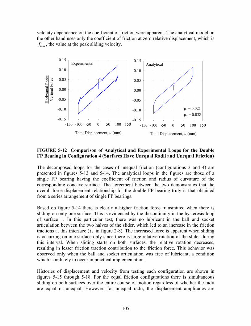
105
velocity dependence on the coefficient of friction were apparent. The analytical model on the other hand uses only the coefficient of friction at zero relative displacement, which is
maxf , the value at the peak sliding velocity.
Experimental
Total Displacement, u (mm)
-150 -100 -50 0 50 100 150
Hor
izon
tal F
orce
Ver
tical
For
ce
-0.15
-0.10
-0.05
0.00
0.05
0.10
0.15Analytical
Total Displacement, u (mm)
-150 -100 -50 0 50 100 150-0.15
-0.10
-0.05
0.00
0.05
0.10
0.15
1 = 0.021
2 = 0.038
FIGURE 5-12 Comparison of Analytical and Experimental Loops for the Double FP Bearing in Configuration 4 (Surfaces Have Unequal Radii and Unequal Friction) The decomposed loops for the cases of unequal friction (configurations 3 and 4) are presented in figures 5-13 and 5-14. The analytical loops in the figures are those of a single FP bearing having the coefficient of friction and radius of curvature of the corresponding concave surface. The agreement between the two demonstrates that the overall force displacement relationship for the double FP bearing truly is that obtained from a series arrangement of single FP bearings. Based on figure 5-14 there is clearly a higher friction force transmitted when there is sliding on only one surface. This is evidenced by the discontinuity in the hysteresis loop of surface 1. In this particular test, there was no lubricant in the ball and socket articulation between the two halves of the slider, which led to an increase in the friction tractions at this interface ( ft in figure 2-8). The increased force is apparent when sliding is occurring on one surface only since there is large relative rotation of the slider during this interval. When sliding starts on both surfaces, the relative rotation decreases, resulting in lesser friction traction contribution to the friction force. This behavior was observed only when the ball and socket articulation was free of lubricant, a condition which is unlikely to occur in practical implementation. Histories of displacement and velocity from testing each configuration are shown in figures 5-15 through 5-18. For the equal friction configurations there is simultaneous sliding on both surfaces over the entire course of motion regardless of whether the radii are equal or unequal. However, for unequal radii, the displacement amplitudes are

106
different because the stiffness of the two surfaces are different. This is predicted by equations (3-9) and (3-10). The displacement on the surface with larger radius of curvature (which is less stiff) is larger than that of the surface with smaller radius of curvature (which is stiffer).
Bottom Surface
Bottom Displacement, u1 (mm)
-75 -50 -25 0 25 50 75
Hor
izon
tal F
orce
Ver
tical
For
ce
-0.20
-0.15
-0.10
-0.05
0.00
0.05
0.10
0.15
0.20Top Surface
Top Displacement, u2 (mm)
-75 -50 -25 0 25 50 75-0.20
-0.15
-0.10
-0.05
0.00
0.05
0.10
0.15
0.20
ExperimentalAnalytical
1 = 0.011Reff1 = 441 mm
2 = 0.083Reff2 = 437 mm
FIGURE 5-13 Decomposed Hysteresis Loops for the Double FP Bearing in Configuration 3 (Surfaces Have Equal Radii and Unequal Friction)
Bottom Surface
Bottom Displacement, u1 (mm)
-75 -50 -25 0 25 50 75
Hor
izon
tal F
orce
Ver
tical
For
ce
-0.15
-0.10
-0.05
0.00
0.05
0.10
0.15Top Surface
Top Displacement, u2 (mm)
-75 -50 -25 0 25 50 75-0.15
-0.10
-0.05
0.00
0.05
0.10
0.15
ExperimentalAnalytical
1 = 0.021Reff1 = 441 mm
2 = 0.038Reff2 = 726 mm
FIGURE 5-14 Decomposed Hysteresis Loops for the Double FP Bearing in Configuration 4 (Surfaces Have Unequal Radii and Unequal Friction)

107
0 5 10 15 20 25 30
Dis
plac
emen
t (m
m)
-150
-100
-50
0
50
100
150
Time (sec)
0 5 10 15 20 25 30
Vel
ocity
(mm
/s)
-75
-50
-25
0
25
50
75
TotalBottomTop
FIGURE 5-15 Histories of Displacement for the Double FP Bearing in Configuration 1 (Surfaces Have Equal Radii and Equal Friction)
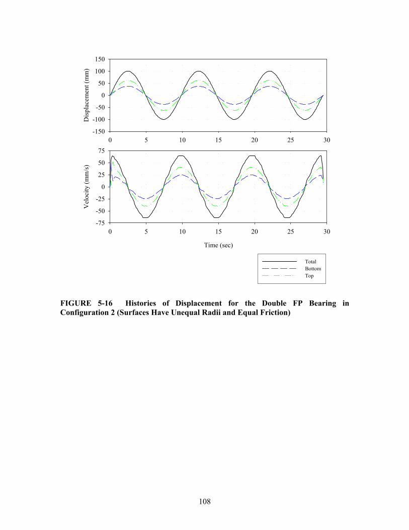
108
0 5 10 15 20 25 30
Dis
plac
emen
t (m
m)
-150
-100
-50
0
50
100
150
Time (sec)
0 5 10 15 20 25 30
Vel
ocity
(mm
/s)
-75
-50
-25
0
25
50
75
TotalBottomTop
FIGURE 5-16 Histories of Displacement for the Double FP Bearing in Configuration 2 (Surfaces Have Unequal Radii and Equal Friction)

109
0 5 10 15 20 25 30
Dis
plac
emen
t (m
m)
-150
-100
-50
0
50
100
150
Time (sec)
0 5 10 15 20 25 30
Vel
ocity
(mm
/s)
-75
-50
-25
0
25
50
75
TotalBottomTop
FIGURE 5-17 Histories of Displacement for the Double FP Bearing in Configuration 3 (Surfaces Have Equal Radii and Unequal Friction)
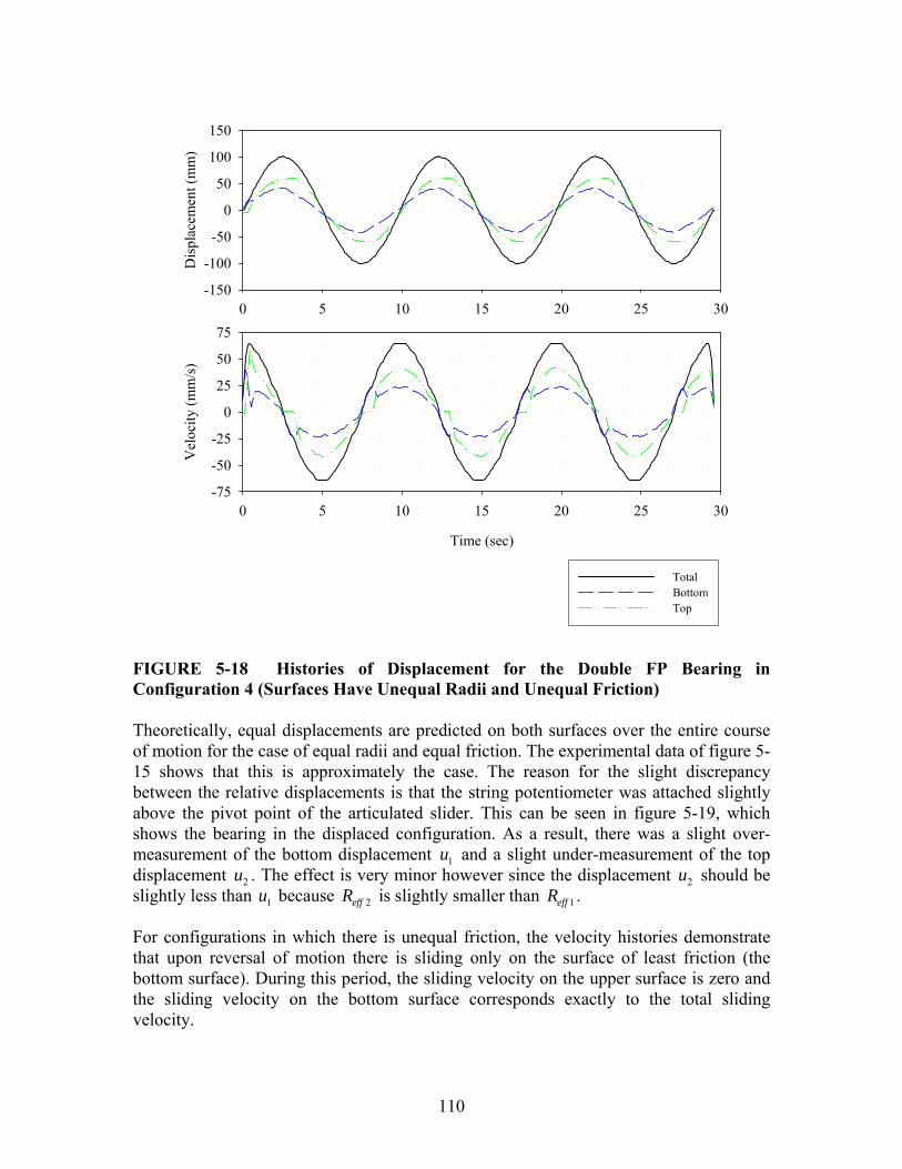
110
0 5 10 15 20 25 30
Dis
plac
emen
t (m
m)
-150
-100
-50
0
50
100
150
Time (sec)
0 5 10 15 20 25 30
Vel
ocity
(mm
/s)
-75
-50
-25
0
25
50
75
TotalBottomTop
FIGURE 5-18 Histories of Displacement for the Double FP Bearing in Configuration 4 (Surfaces Have Unequal Radii and Unequal Friction) Theoretically, equal displacements are predicted on both surfaces over the entire course of motion for the case of equal radii and equal friction. The experimental data of figure 5-15 shows that this is approximately the case. The reason for the slight discrepancy between the relative displacements is that the string potentiometer was attached slightly above the pivot point of the articulated slider. This can be seen in figure 5-19, which shows the bearing in the displaced configuration. As a result, there was a slight over-measurement of the bottom displacement 1u and a slight under-measurement of the top displacement 2u . The effect is very minor however since the displacement 2u should be slightly less than 1u because 2effR is slightly smaller than 1effR . For configurations in which there is unequal friction, the velocity histories demonstrate that upon reversal of motion there is sliding only on the surface of least friction (the bottom surface). During this period, the sliding velocity on the upper surface is zero and the sliding velocity on the bottom surface corresponds exactly to the total sliding velocity.

111
FIGURE 5-19 Double FP Bearing Displaced During Cyclic Testing (Zip Ties Denote Location of String Potentiometer Attachment) The phenomenon of slider offset described in section 3.5.6 is also evident in the displacement histories. For the equal friction cases, when the total displacement passes through zero the relative displacements are zero at that instant as well. In the configurations with unequal friction, at the instant the total displacement passes through zero there are equal and opposite nonzero relative displacements. The experimentally measured values of the offset are typically within 1 mm of the analytical values (15.8 mm for configuration 3 and 4.7 mm for configuration 4). Furthermore, the experimental data demonstrates that this offset does not accumulate from cycle to cycle and remains consistently u′ . 5.5.3 Behavior After Contacting the Displacement Restrainer (Sliding Regime III) The second test sequence for the double FP bearings emphasized configurations having different displacement capacity and investigated the effect of contacting the displacement restrainer. Configurations 5, 6 and 7 used the urethane ring installed as shown in figure 5-20 to reduce the displacement capacity of a given surface. The figure also shows how the string potentiometer was attached closer to the pivot point of the articulated slider for this test sequence in order to get more accurate measurements of relative displacement. Furthermore, each configuration was tested at a range of displacement amplitudes to demonstrate the full adaptive nature of the behavior.

112
FIGURE 5-20 Double FP Bearing Having Surfaces of Different Displacement Capacity Displaced During Cyclic Testing (Installation Typical of Configurations 5 and 7) Experimental and analytical force-displacement data is given in figures 5-21 through 5-23 for double FP configurations 5, 6 and 7. The parameters that were used to construct the analytical loops are given in table 5-4. In general, the experimental data agrees well with the theoretical results and demonstrates that desirable changes in stiffness and damping occur with increasing amplitude of displacement. It should be noted that in configuration 7, the double FP bearing exhibits increases in both stiffness and damping at large displacements after the slider contacts the displacement restrainer on the surface of least friction. This is the only configuration of all the multi-spherical sliding bearings tested that exhibits increases in both stiffness and damping prior to achieving the total displacement capacity of the bearing. Decomposed loops of configuration 7 from the 115 mm amplitude test are shown in figure 5-24. It can be seen that when the slider contacts the displacement restrainer on surface 1, the decomposed loop of this surface shows a substantial increase in stiffness. The experimentally obtained behavior is as proposed analytically in figure 2-10. The only difference is that theoretically the displacement restrainer is assumed to be rigid. In the experiment, the displacement restrainer exhibited a finite stiffness. Durometer 62D is approximately the hardness of a golf ball, so although very stiff, the displacement restrainer did deform slightly. This can easily be accounted for in the analytical model by using a finite value of drk in equation (2-6) The decomposed loop of the other sliding surface, where the slider has not contacted the displacement restrainer is unaffected and appears simply as that of a traditional single concave FP bearing.

113
Table 5-4 Coefficients of Friction and Displacement Capacities Measured During Experiments used to Construct Analytical Force-Displacement Loops for Double FP Bearing Configuration 5-7
Configuration Sliding Regime Amplitude Coefficients of Friction Displacement
Capacities I 75 mm 1 20.021, 0.024μ = μ =
Double 5 II 115 mm 1 20.018, 0.029μ = μ = 1 48 mmd =
I 1.5 mm 1 20.015,μ = μ = −
II 75 mm 1 20.016, 0.022μ = μ = Double 6 III 115 mm 1 20.015, 0.024μ = μ =
2 50 mmd =
I 1.5 mm 1 20.016,μ = μ = −
II 75 mm 1 20.015, 0.022μ = μ =
III(a) 95 mm 1 20.016, 0.025μ = μ = Double 7
III(b) 115 mm 1 20.011, 0.029μ = μ =
1 48 mmd =
Experimental
Total Displacement, u (mm)
-150 -100 -50 0 50 100 150
Hor
izon
tal F
orce
Ver
tical
For
ce
-0.2
-0.1
0.0
0.1
0.2Analytical
Total Displacement, u (mm)
-150 -100 -50 0 50 100 150-0.2
-0.1
0.0
0.1
0.2
1 = 0.018 - 0.021
2 = 0.024 - 0.029d1 = 48 mm
FIGURE 5-21 Comparison of Analytical and Experimental Loops for the Double FP Bearing in Configuration 5
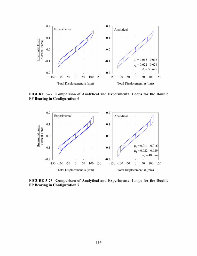
114
Experimental
Total Displacement, u (mm)
-150 -100 -50 0 50 100 150
Hor
izon
tal F
orce
Ver
tical
For
ce
-0.2
-0.1
0.0
0.1
0.2Analytical
Total Displacement, u (mm)
-150 -100 -50 0 50 100 150-0.2
-0.1
0.0
0.1
0.2
1 = 0.015 - 0.016
2 = 0.022 - 0.024d2 = 50 mm
FIGURE 5-22 Comparison of Analytical and Experimental Loops for the Double FP Bearing in Configuration 6
Experimental
Total Displacement, u (mm)
-150 -100 -50 0 50 100 150
Hor
izon
tal F
orce
Ver
tical
For
ce
-0.2
-0.1
0.0
0.1
0.2Analytical
Total Displacement, u (mm)
-150 -100 -50 0 50 100 150-0.2
-0.1
0.0
0.1
0.2
1 = 0.011 - 0.016
2 = 0.022 - 0.029d1 = 48 mm
FIGURE 5-23 Comparison of Analytical and Experimental Loops for the Double FP Bearing in Configuration 7
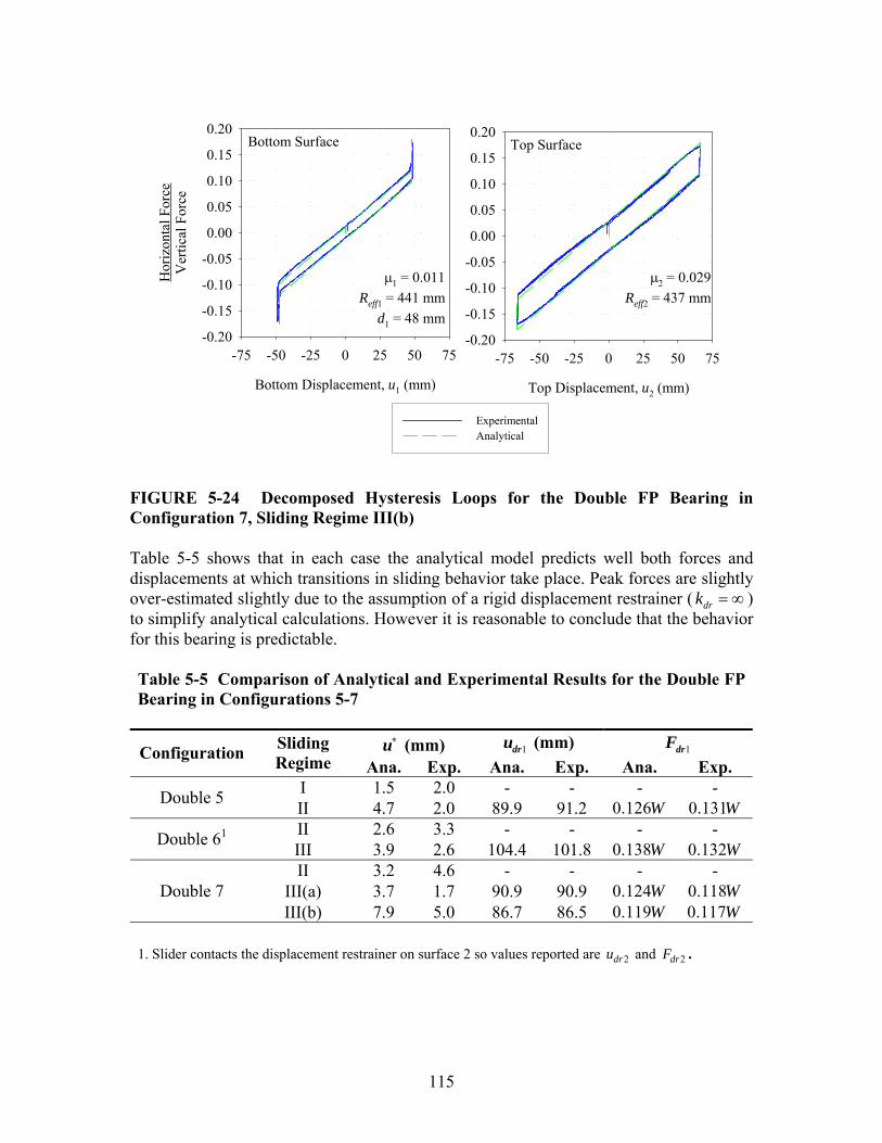
115
Bottom Surface
Bottom Displacement, u1 (mm)
-75 -50 -25 0 25 50 75
Hor
izon
tal F
orce
Ver
tical
For
ce
-0.20
-0.15
-0.10
-0.05
0.00
0.05
0.10
0.15
0.20Top Surface
Top Displacement, u2 (mm)
-75 -50 -25 0 25 50 75-0.20
-0.15
-0.10
-0.05
0.00
0.05
0.10
0.15
0.20
ExperimentalAnalytical
1 = 0.011Reff1 = 441 mm
d1 = 48 mm
2 = 0.029Reff2 = 437 mm
FIGURE 5-24 Decomposed Hysteresis Loops for the Double FP Bearing in Configuration 7, Sliding Regime III(b) Table 5-5 shows that in each case the analytical model predicts well both forces and displacements at which transitions in sliding behavior take place. Peak forces are slightly over-estimated slightly due to the assumption of a rigid displacement restrainer ( drk = ∞ ) to simplify analytical calculations. However it is reasonable to conclude that the behavior for this bearing is predictable. Table 5-5 Comparison of Analytical and Experimental Results for the Double FP Bearing in Configurations 5-7
∗u (mm) 1dru (mm) 1drF Configuration Sliding
Regime Ana. Exp. Ana. Exp. Ana. Exp. I 1.5 2.0 - - - - Double 5 II 4.7 2.0 89.9 91.2 0.126W 0.131W II 2.6 3.3 - - - - Double 61 III 3.9 2.6 104.4 101.8 0.138W 0.132WII 3.2 4.6 - - - -
III(a) 3.7 1.7 90.9 90.9 0.124W 0.118WDouble 7 III(b) 7.9 5.0 86.7 86.5 0.119W 0.117W
1. Slider contacts the displacement restrainer on surface 2 so values reported are 2dru and 2drF .
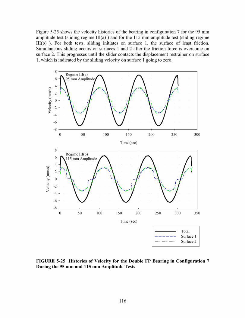
116
Figure 5-25 shows the velocity histories of the bearing in configuration 7 for the 95 mm amplitude test (sliding regime III(a) ) and for the 115 mm amplitude test (sliding regime III(b) ). For both tests, sliding initiates on surface 1, the surface of least friction. Simultaneous sliding occurs on surfaces 1 and 2 after the friction force is overcome on surface 2. This progresses until the slider contacts the displacement restrainer on surface 1, which is indicated by the sliding velocity on surface 1 going to zero.
Regime III(a)95 mm Amplitude
Time (sec)
0 50 100 150 200 250 300
Vel
ocity
(mm
/s)
-8
-6
-4
-2
0
2
4
6
8
Regime III(b)115 mm Amplitude
Time (sec)
0 50 100 150 200 250 300 350
Vel
ocity
(mm
/s)
-8
-6
-4
-2
0
2
4
6
8
TotalSurface 1Surface 2
FIGURE 5-25 Histories of Velocity for the Double FP Bearing in Configuration 7 During the 95 mm and 115 mm Amplitude Tests

117
Upon reversal of motion the two plots demonstrate the different sequences in which sliding can resume. In the 95 mm amplitude test, equation (3-19) is not satisfied ( max 98.2 mm<u ) and motion resumes on surface 1 prior to surface 2. In the 115 mm amplitude test, equation (3-19) is satisfied ( max 102.4 mm>u ) and motion resumes on surface 2 prior to surface 1. It should also be noted that in configuration 6 the condition expressed by equation (3-19) was always satisfied since 1 2μ < μ . Accordingly only one order of unloading was observed (i.e. there is only a sliding regime III, not III(a) and III(b)). This phenomenon admittedly may have only a small impact on global structure response; however the fact that the analytical model captures such nuanced behavior gives added confidence its overall validity. 5.6 Experimental Results for the Triple FP Bearing 5.6.1 Quantitative Comparison of Experimental and Analytical Results Analytical loops for the triple FP bearing were determined in a similar fashion as for the double FP bearing using the theory presented in section 4 and the coefficients of friction given in table 5-6. For surfaces 1 and 4, the coefficients of friction reported are determined as described in section 5.5.1. For surfaces 2 and 3 however, it will be shown that the decomposed force-displacement loops are atypical. Therefore, the experimental values of the coefficients of friction reported for these surfaces were determined as half the drop in the normalized force that occurred upon reversal of motion. The experimental data presented in figure 5-26 shows one test typical of each sliding regime for the triple FP bearing in configuration 1. The loops clearly show the various transitions in stiffness that occur over the course of motion as the combinations of surfaces upon which sliding is occurring change. It is emphasized that the increase in strength exhibited by the bearing with increasing displacement is a result of its internal mechanical behavior, not of the variability in the coefficients of friction due to velocity effects. The increase is a result of sliding occurring on surface 4, which is of substantially higher friction. In general there is very good agreement between the experimental data and the analytical loops constructed using the actual values of friction and displacement capacity. As summarized in table 5-7, the analytical model matches quite well in terms of both the values of normalized force and the displacements at which transitions in stiffness occur. The experimentally recorded force-displacement loops also show very little variability from cycle to cycle. Provided the coefficients of friction remain consistent, the transitions in stiffness will occur at the same forces and displacements from cycle to cycle. There is no ratcheting or accumulation of displacement offsets with repeated cycling.

118
Table 5-6 Coefficients of Friction and Displacement Capacities Measured During Experiments used to Construct Analytical Force-Displacement Loops for Triple FP Bearing Configurations 1-3
Configuration Sliding Regime Amplitude Coefficients of Friction Displacement
Capacities
I 1.2 mm 2 3 0.022μ = μ =
1 4,μ = − μ = −
II 25 mm 2 3 0.010μ = μ =
1 40.038,μ = μ = −
III 75 mm 2 3 0.025μ = μ =
1 40.041, 0.129μ = μ =
IV 115 mm 2 3 0.010μ = μ =
1 40.022, 0.119μ = μ =
Triple 1
V 140 mm 2 3 0.019μ = μ =
1 40.021, 0.099μ = μ =
1 61 mmd =
4 61 mmd =
IV 100 mm 2 3 0.013μ = μ =
1 40.028, 0.084μ = μ = Triple 2
V 120 mm 2 3 0.017μ = μ =
1 40.025, 0.061μ = μ =
1 37 mmd =
4 61 mmd =
IV 100 mm 2 3 0.016μ = μ =
1 40.027, 0.081μ = μ = Triple 3
V 115 mm 2 3 0.017μ = μ =
1 40.029, 0.071μ = μ =
1 61 mmd =
4 37 mmd =
The largest difference between theory and experiment occurs in the 140 mm amplitude test where there is slight stiffening prior to the slider contacting the displacement restrainer on surface 4. This is not captured in the analytical model. Also the stiffness exhibited for the final phase of sliding regime V is somewhat higher than what is predicted by theory. The experimental value of stiffness determined by linear regression is ( )82 mmW , however the theoretical value is ( )106 mmW . This leads to an underestimation of the force at maximum displacement by approximately 15%, despite very close prediction of the displacement at which the transition in stiffness occurs, 4dru . This discrepancy is due to a combination of the greater error in the small angle assumption (at the peak displacement of 140 mm the rigid slider is inclined at 16°) and errors introduced in the test apparatus and load cell at large displacements.

119
Experimental
-150 -100 -50 0 50 100 150
Hor
izon
tal F
orce
Ver
tical
For
ce
-0.4
-0.3
-0.2
-0.1
0.0
0.1
0.2
0.3
0.4
Analytical
Total Displacement, u (mm)
-150 -100 -50 0 50 100 150
Hor
izon
tal F
orce
Ver
tical
For
ce
-0.4
-0.3
-0.2
-0.1
0.0
0.1
0.2
0.3
0.4
1 = 0.021 - 0.041
2 = 3 = 0.010 - 0.025
4 = 0.099 - 0.129d1 = d4 = 61 mm
FIGURE 5-26 Comparison of Experimental and Analytical Results for Force-Displacement Relationship of Triple FP Specimen in Configuration 1 (Sliding Regimes I – V Shown)

Tab
le 5
-7.
Com
pari
son
of A
naly
tical
and
Exp
erim
enta
l Res
ults
for
the
Tri
ple
FP B
eari
ng
Reg
ime
II
Reg
ime
III
Reg
ime
IV
Reg
ime
V
A
naly
tical
E
xper
imen
tA
naly
tical
E
xper
imen
tA
naly
tical
E
xper
imen
tA
naly
tical
E
xper
imen
tC
onfig
urat
ion
1 u∗
(mm
)1 2.
9 2
2.5
3 1.
3 2
0.1
2 u∗∗
(mm
)1 -
- 45
.5
51
48.6
41
38
.4
42
1dru
(mm
)2 -
- -
- 86
.2
85
92.1
90
4dru
(mm
)2 -
- -
- -
- 13
0.4
130
1drF
2 -
- -
- 0.
162W
0.
172W
0.
161W
0.
173W
4drF
2 -
- -
- -
- 0.
240W
0.
272W
C
onfig
urat
ion
2 u∗
(mm
)1 -
- -
- 1.
6 2.
8 0.
9 1.
9 u∗∗
(mm
)1 -
- -
- 29
.0
29.3
18
.4
27.6
1
dru (m
m)2
- -
- -
54.2
52
.6
63.3
60
.9
4dru
(mm
)2 -
- -
- -
- 10
6.5
108.
0
1drF
2 -
- -
- 0.
113W
0.
111W
0.
113W
0.
111W
4drF
2 -
- -
- -
- 0.
201W
0.
213W
C
onfig
urat
ion
3 u∗
(mm
)1 -
- -
- 1.
1 1.
8 1.
3 2.
6 u∗∗
(mm
)1 -
- -
- 27
.9
36.7
22
.0
34.6
1
dru (m
m)2
- -
- -
102.
1 99
.3
102.
2 10
2.2
4dru
(mm
)2 -
- -
- -
- 96
.0
93.7
1drF
2 -
- -
- 0.
166W
0.
170W
0.
169W
0.
175W
4drF
2 -
- -
- -
- 0.
156W
0.
158W
1.
Exp
erim
enta
l val
ue is
firs
t cyc
le v
alue
, 2. E
xper
imen
tal v
alue
is th
ree
cycl
e av
erag
e va
lue.
120

121
The agreement between the experimental and analytical behavior is also very good for the other configurations of triple FP bearing. Experimental and analytical data for configurations 2 and 3 are shown in figures 5-27 and 5-28 respectively. Only regimes IV and V were tested since prior to contacting the displacement restrainer, the force-displacement behavior of configurations 2 and 3 is the same as configuration 1. Referring to table 5-7, the forces and displacements at which transitions in stiffness occur are also predicted well. Verification of the analytical model in a variety of configurations contributes towards confirming the overall validity of the basic theory presented in this report.
Experimental
Total Displacement, u (mm)
-150 -100 -50 0 50 100 150
Hor
izon
tal F
orce
Ver
tical
For
ce
-0.4
-0.3
-0.2
-0.1
0.0
0.1
0.2
0.3
0.4Analytical
Total Displacement, u (mm)
-150 -100 -50 0 50 100 150-0.4
-0.3
-0.2
-0.1
0.0
0.1
0.2
0.3
0.4
1 = 0.025 - 0.028
2 = 3 = 0.013 - 0.017
4 = 0.061 - 0.084d1 = 37 mm, d4 = 61 mm
FIGURE 5-27 Comparison of Experimental and Analytical Results for Force-Displacement Relationship of Triple FP Specimen in Configuration 2 (Sliding Regimes IV and V Shown)
Experimental
Total Displacement, u (mm)
-150 -100 -50 0 50 100 150
Hor
izon
tal F
orce
Ver
tical
For
ce
-0.3
-0.2
-0.1
0.0
0.1
0.2
0.3Analytical
Total Displacement, u (mm)
-150 -100 -50 0 50 100 150-0.3
-0.2
-0.1
0.0
0.1
0.2
0.3
1 = 0.027 - 0.029
2 = 3 = 0.016 - 0.017
4 = 0.071 - 0.081d1 = 61 mm, d4 = 37 mm
FIGURE 5-28 Comparison of Experimental and Analytical Results for Force-Displacement Relationship of Triple FP Specimen in Configuration 3 (Sliding Regimes IV and V Shown)
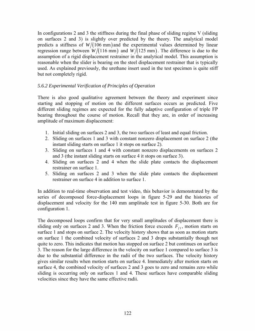
122
In configurations 2 and 3 the stiffness during the final phase of sliding regime V (sliding on surfaces 2 and 3) is slightly over predicted by the theory. The analytical model predicts a stiffness of ( )106 mmW and the experimental values determined by linear regression range between ( )116 mmW and ( )125 mmW . The difference is due to the assumption of a rigid displacement restrainer in the analytical model. This assumption is reasonable when the slider is bearing on the steel displacement restrainer that is typically used. As explained previously, the urethane insert used in the test specimen is quite stiff but not completely rigid. 5.6.2 Experimental Verification of Principles of Operation There is also good qualitative agreement between the theory and experiment since starting and stopping of motion on the different surfaces occurs as predicted. Five different sliding regimes are expected for the fully adaptive configuration of triple FP bearing throughout the course of motion. Recall that they are, in order of increasing amplitude of maximum displacement:
1. Initial sliding on surfaces 2 and 3, the two surfaces of least and equal friction. 2. Sliding on surfaces 1 and 3 with constant nonzero displacement on surface 2 (the
instant sliding starts on surface 1 it stops on surface 2). 3. Sliding on surfaces 1 and 4 with constant nonzero displacements on surfaces 2
and 3 (the instant sliding starts on surface 4 it stops on surface 3). 4. Sliding on surfaces 2 and 4 when the slide plate contacts the displacement
restrainer on surface 1. 5. Sliding on surfaces 2 and 3 when the slide plate contacts the displacement
restrainer on surface 4 in addition to surface 1. In addition to real-time observation and test video, this behavior is demonstrated by the series of decomposed force-displacement loops in figure 5-29 and the histories of displacement and velocity for the 140 mm amplitude test in figure 5-30. Both are for configuration 1. The decomposed loops confirm that for very small amplitudes of displacement there is sliding only on surfaces 2 and 3. When the friction force exceeds 1fF , motion starts on surface 1 and stops on surface 2. The velocity history shows that as soon as motion starts on surface 1 the combined velocity of surfaces 2 and 3 drops substantially though not quite to zero. This indicates that motion has stopped on surface 2 but continues on surface 3. The reason for the large difference in the velocity on surface 1 compared to surface 3 is due to the substantial difference in the radii of the two surfaces. The velocity history gives similar results when motion starts on surface 4. Immediately after motion starts on surface 4, the combined velocity of surfaces 2 and 3 goes to zero and remains zero while sliding is occurring only on surfaces 1 and 4. These surfaces have comparable sliding velocities since they have the same effective radii.
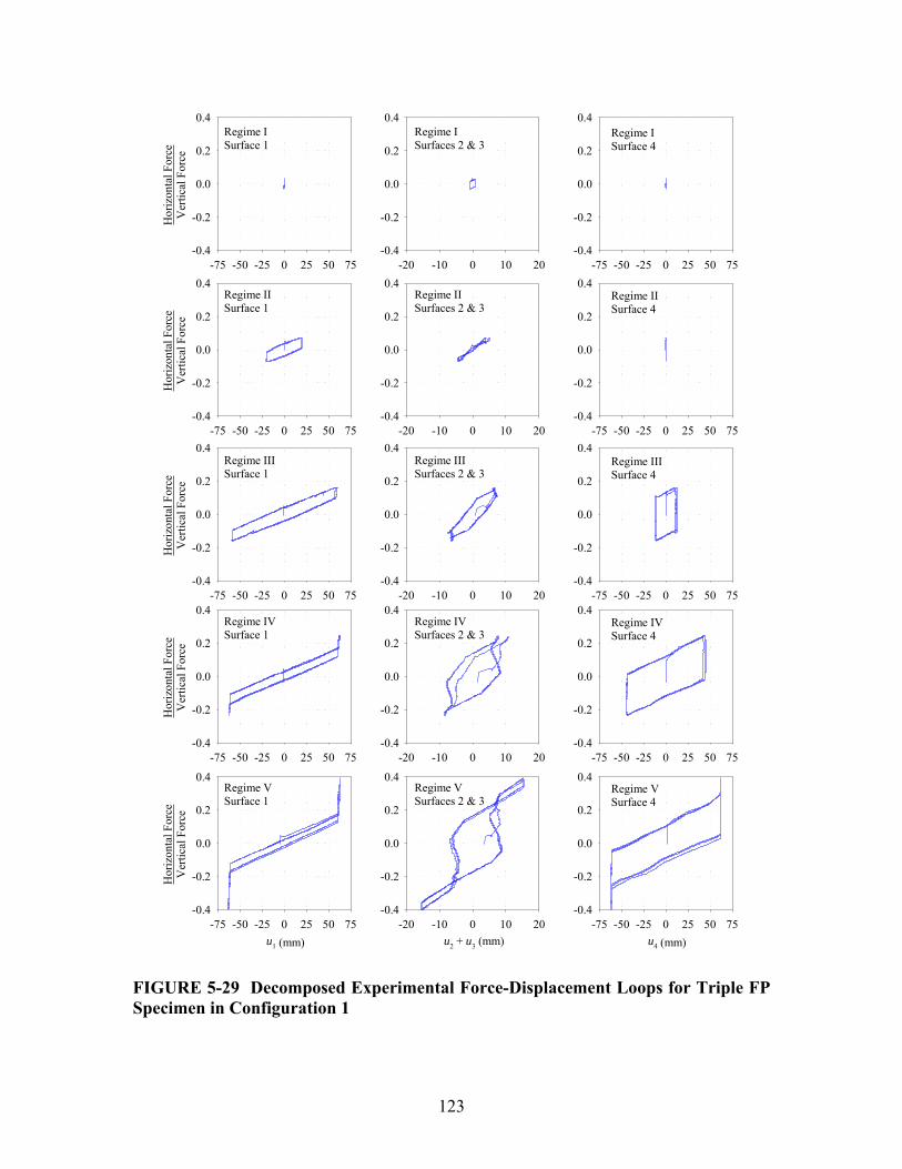
123
Regime VSurface 1
u1 (mm)-75 -50 -25 0 25 50 75
Hor
izon
tal F
orce
Ver
tical
For
ce
-0.4
-0.2
0.0
0.2
0.4Regime VSurfaces 2 & 3
u2 + u3 (mm)-20 -10 0 10 20
-0.4
-0.2
0.0
0.2
0.4Regime VSurface 4
u4 (mm)-75 -50 -25 0 25 50 75
-0.4
-0.2
0.0
0.2
0.4
Regime IVSurface 1
-75 -50 -25 0 25 50 75
Hor
izon
tal F
orce
Ver
tical
For
ce
-0.4
-0.2
0.0
0.2
0.4Regime IVSurfaces 2 & 3
-20 -10 0 10 20-0.4
-0.2
0.0
0.2
0.4Regime IVSurface 4
-75 -50 -25 0 25 50 75-0.4
-0.2
0.0
0.2
0.4
Regime IIISurface 1
-75 -50 -25 0 25 50 75
Hor
izon
tal F
orce
Ver
tical
For
ce
-0.4
-0.2
0.0
0.2
0.4Regime IIISurfaces 2 & 3
-20 -10 0 10 20-0.4
-0.2
0.0
0.2
0.4Regime IIISurface 4
-75 -50 -25 0 25 50 75-0.4
-0.2
0.0
0.2
0.4
Regime IISurface 1
-75 -50 -25 0 25 50 75
Hor
izon
tal F
orce
Ver
tical
For
ce
-0.4
-0.2
0.0
0.2
0.4Regime IISurfaces 2 & 3
-20 -10 0 10 20-0.4
-0.2
0.0
0.2
0.4Regime IISurface 4
-75 -50 -25 0 25 50 75-0.4
-0.2
0.0
0.2
0.4
Regime ISurface 1
-75 -50 -25 0 25 50 75
Hor
izon
tal F
orce
Ver
tical
For
ce
-0.4
-0.2
0.0
0.2
0.4Regime ISurfaces 2 & 3
-20 -10 0 10 20-0.4
-0.2
0.0
0.2
0.4Regime ISurface 4
-75 -50 -25 0 25 50 75-0.4
-0.2
0.0
0.2
0.4
FIGURE 5-29 Decomposed Experimental Force-Displacement Loops for Triple FP Specimen in Configuration 1

124
Time (sec)
0 50 100 150 200 250 300 350 400 450
Dis
plac
emen
t (m
m)
-150
-100
-50
0
50
100
150
Time (sec)
0 50 100 150 200 250 300 350 400 450
Vel
ocity
(mm
/s)
-8
-6
-4
-2
0
2
4
6
8
TotalSurface 1Surfaces 2 & 3Surface 4
FIGURE 5-30 Experimental Histories of Displacement and Velocity for the Triple FP Bearing in Configuration 1 During Cyclic Testing of 140 mm Amplitude The instant motion starts on surface 4, the combined displacement of surfaces 2 and 3 should be 6.4 mm according to equation (4-7) and remain constant at this value. The experimentally measured value of this displacement is approximately 7 mm. Theory predicts that this displacement should remain constant as long as sliding is occurring on both surfaces 1 and 4. However, the experimental data in figure 5-29 for surfaces 2 and 3 during sliding regimes III-V shows a slight reduction in this value as the force increases. This reduction (marked by the segments with negative slope) is due to error induced in the string pot measurements by the rotation of the slide plates. Though the slide plates do not translate relative to one another, when they rotate the lengths of the string

125
potentiometers change since they are not attached at the pivot point. One string will lengthen and the other will shorten giving the impression that the relative displacement between the two is actually decreasing. This occurs slowly compared to translation and can be distinguished from true relative sliding between the plates by inspection of the velocity history. During sliding regime IV, motion resumes on surface 2 as the slider contacts the displacement restrainer of surface 1. This is evidenced both by the hysteresis loop of surfaces 2 and 3 during regime IV and the velocity history of figure 5-30. When the velocity on surface 1 drops to zero there is a slight increase in the combined velocities of surfaces 2 and 3. Furthermore, the decomposed hysteresis loop of surface 1 agrees well with the assumed behavior for a slider that contacts the displacement restrainer. The behavior is identical to the decomposed loop of the double FP bearing shown in figure 5-24. This is a fundamental behavior that applies to all spherical sliding bearings. At the start of sliding regime V, both slide plates have contacted the displacement restrainers and there is sliding only on surfaces 2 and 3. The sliding velocities on surfaces 1 and 4 both are zero and the combined velocity of surfaces 2 and 3 overlays exactly the total velocity. The hysteresis loops of surfaces 2 and 3 demonstrate rigid linear behavior after the displacement restrainer is contacted on surface 4. Lastly, the phenomenon of slider offset can be seen in the histories of displacement and velocity of figure 5-30. When the total displacement is zero, the individual displacements on each of the sliding surfaces are all nonzero (though they must sum to zero). For the 140 mm amplitude test, the experimental values of the offsets are -13.4 mm for surface 1, -6.4 mm for surfaces 2 and 3 combined and 19.8 mm for surface 4 (3 cycle average values). These are in good agreement with the values obtained by tracking the analytical force-displacement loops: -14.9 mm, -4.3 mm and 19.2 mm respectively. The offset results from the displacement controlled nature of the testing and is different from the permanent total displacements after earthquake excitation. 5.6.3 Comments on Tests at High Speed The results of the tests carried out at high speed are shown in figure 5-31 and indicate that the behavior under dynamic conditions is essentially the same as the behavior exhibited under quasi-static conditions. Due to the wider range in values of the coefficients of friction, the transitions in stiffness between sliding regimes are less clear. For the purposes of this study, this makes it more difficult to precisely identify the transitions between sliding regimes. However, for practical applications gradual transitions are more beneficial when considering the response of secondary systems as abrupt changes in stiffness may lead to excitation of higher modes. The consistency of behavior from the 0.10 Hz frequency test to the 0.60 Hz frequency test should be also noted. Although the peak sliding velocity on each surface increases with increasing frequency, the velocities are large enough so that the coefficient of friction remains constant with increasing velocity.

126
0.01 Hz FrequencyPeak Velocity = 7.2 mm/s
-150 -100 -50 0 50 100 150
Hor
izon
tal F
orce
Ver
tical
For
ce
-0.3
-0.2
-0.1
0.0
0.1
0.2
0.30.10 Hz FrequencyPeak Velocity = 72 mm/s
-150 -100 -50 0 50 100 150-0.3
-0.2
-0.1
0.0
0.1
0.2
0.3
0.30 Hz FrequencyPeak Velocity = 216 mm/s
-150 -100 -50 0 50 100 150
Hor
izon
tal F
orce
Ver
tical
For
ce
-0.3
-0.2
-0.1
0.0
0.1
0.2
0.30.50 Hz FrequencyPeak Velocity = 359 mm/s
Total Displacement, u (mm)
-150 -100 -50 0 50 100 150-0.3
-0.2
-0.1
0.0
0.1
0.2
0.3
0.60 Hz FrequencyPeak Velocity = 431 mm/s
Total Displacement, u (mm)
-150 -100 -50 0 50 100 150
Hor
izon
tal F
orce
Ver
tical
For
ce
-0.3
-0.2
-0.1
0.0
0.1
0.2
0.3
FIGURE 5-31 Force-Displacement Loops for Triple FP Specimen in Configuration 1 During Testing at 115 mm Amplitude and Increasing Frequency of Sinusoidal Motion (Peak Velocities are Experimentally Measured Values and Differ Slightly from the Nominal or Target Values)
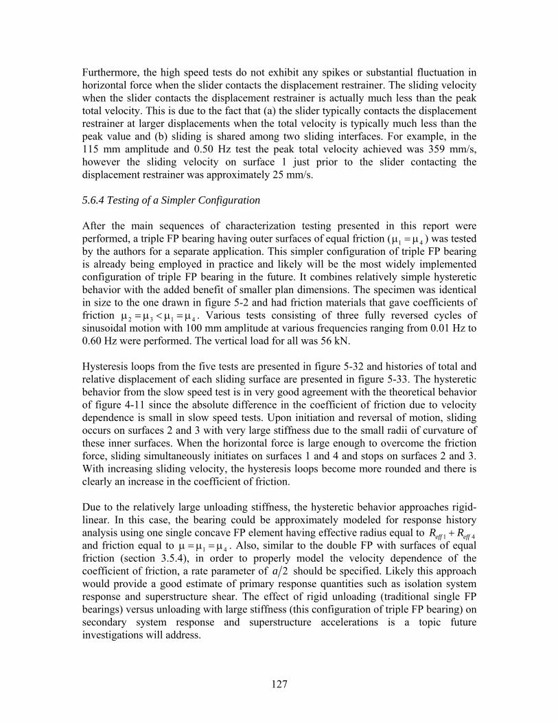
127
Furthermore, the high speed tests do not exhibit any spikes or substantial fluctuation in horizontal force when the slider contacts the displacement restrainer. The sliding velocity when the slider contacts the displacement restrainer is actually much less than the peak total velocity. This is due to the fact that (a) the slider typically contacts the displacement restrainer at larger displacements when the total velocity is typically much less than the peak value and (b) sliding is shared among two sliding interfaces. For example, in the 115 mm amplitude and 0.50 Hz test the peak total velocity achieved was 359 mm/s, however the sliding velocity on surface 1 just prior to the slider contacting the displacement restrainer was approximately 25 mm/s. 5.6.4 Testing of a Simpler Configuration After the main sequences of characterization testing presented in this report were performed, a triple FP bearing having outer surfaces of equal friction ( 1 4μ = μ ) was tested by the authors for a separate application. This simpler configuration of triple FP bearing is already being employed in practice and likely will be the most widely implemented configuration of triple FP bearing in the future. It combines relatively simple hysteretic behavior with the added benefit of smaller plan dimensions. The specimen was identical in size to the one drawn in figure 5-2 and had friction materials that gave coefficients of friction 2 3 1 4μ = μ < μ = μ . Various tests consisting of three fully reversed cycles of sinusoidal motion with 100 mm amplitude at various frequencies ranging from 0.01 Hz to 0.60 Hz were performed. The vertical load for all was 56 kN. Hysteresis loops from the five tests are presented in figure 5-32 and histories of total and relative displacement of each sliding surface are presented in figure 5-33. The hysteretic behavior from the slow speed test is in very good agreement with the theoretical behavior of figure 4-11 since the absolute difference in the coefficient of friction due to velocity dependence is small in slow speed tests. Upon initiation and reversal of motion, sliding occurs on surfaces 2 and 3 with very large stiffness due to the small radii of curvature of these inner surfaces. When the horizontal force is large enough to overcome the friction force, sliding simultaneously initiates on surfaces 1 and 4 and stops on surfaces 2 and 3. With increasing sliding velocity, the hysteresis loops become more rounded and there is clearly an increase in the coefficient of friction. Due to the relatively large unloading stiffness, the hysteretic behavior approaches rigid-linear. In this case, the bearing could be approximately modeled for response history analysis using one single concave FP element having effective radius equal to 1 4eff effR R+ and friction equal to 1 4μ = μ = μ . Also, similar to the double FP with surfaces of equal friction (section 3.5.4), in order to properly model the velocity dependence of the coefficient of friction, a rate parameter of 2a should be specified. Likely this approach would provide a good estimate of primary response quantities such as isolation system response and superstructure shear. The effect of rigid unloading (traditional single FP bearings) versus unloading with large stiffness (this configuration of triple FP bearing) on secondary system response and superstructure accelerations is a topic future investigations will address.
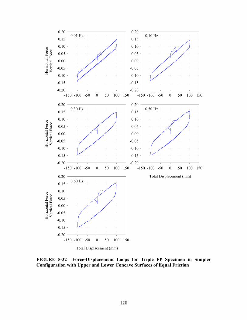
128
-150 -100 -50 0 50 100 150
Hor
izon
tal F
orce
Ver
tical
For
ce
-0.20
-0.15
-0.10
-0.05
0.00
0.05
0.10
0.15
0.20
-150 -100 -50 0 50 100 150-0.20
-0.15
-0.10
-0.05
0.00
0.05
0.10
0.15
0.20
-150 -100 -50 0 50 100 150
Hor
izon
tal F
orce
Ver
tical
For
ce
-0.20
-0.15
-0.10
-0.05
0.00
0.05
0.10
0.15
0.20
Total Displacement (mm)
-150 -100 -50 0 50 100 150-0.20
-0.15
-0.10
-0.05
0.00
0.05
0.10
0.15
0.20
Total Displacement (mm)
-150 -100 -50 0 50 100 150
Hor
izon
tal F
orce
Ver
tical
For
ce
-0.20
-0.15
-0.10
-0.05
0.00
0.05
0.10
0.15
0.20
0.01 Hz 0.10 Hz
0.30 Hz 0.50 Hz
0.60 Hz
FIGURE 5-32 Force-Displacement Loops for Triple FP Specimen in Simpler Configuration with Upper and Lower Concave Surfaces of Equal Friction
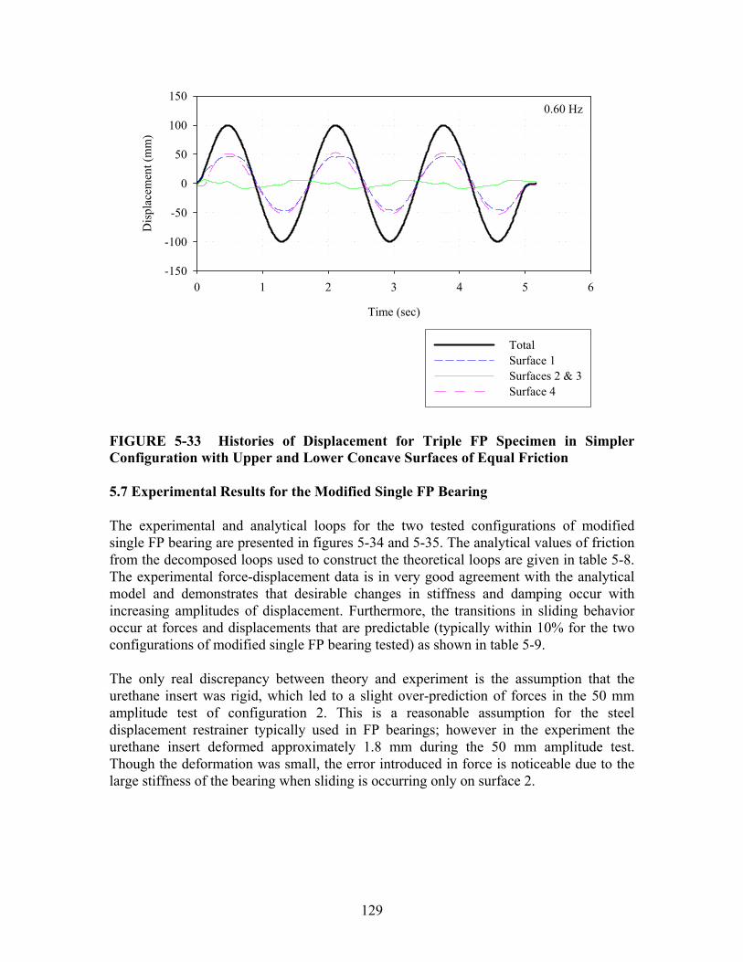
129
Time (sec)
0 1 2 3 4 5 6
Dis
plac
emen
t (m
m)
-150
-100
-50
0
50
100
150
TotalSurface 1Surfaces 2 & 3Surface 4
0.60 Hz
FIGURE 5-33 Histories of Displacement for Triple FP Specimen in Simpler Configuration with Upper and Lower Concave Surfaces of Equal Friction 5.7 Experimental Results for the Modified Single FP Bearing The experimental and analytical loops for the two tested configurations of modified single FP bearing are presented in figures 5-34 and 5-35. The analytical values of friction from the decomposed loops used to construct the theoretical loops are given in table 5-8. The experimental force-displacement data is in very good agreement with the analytical model and demonstrates that desirable changes in stiffness and damping occur with increasing amplitudes of displacement. Furthermore, the transitions in sliding behavior occur at forces and displacements that are predictable (typically within 10% for the two configurations of modified single FP bearing tested) as shown in table 5-9. The only real discrepancy between theory and experiment is the assumption that the urethane insert was rigid, which led to a slight over-prediction of forces in the 50 mm amplitude test of configuration 2. This is a reasonable assumption for the steel displacement restrainer typically used in FP bearings; however in the experiment the urethane insert deformed approximately 1.8 mm during the 50 mm amplitude test. Though the deformation was small, the error introduced in force is noticeable due to the large stiffness of the bearing when sliding is occurring only on surface 2.
130
Table 5-8 Coefficients of Friction and Displacement Capacities Measured During Experiments used to Construct Analytical Force-Displacement Loops for Modified Single FP Bearing Configurations 1and 2
Configuration Sliding Regime Amplitude Coefficients of friction Displaceme
nt capacities I 1 mm 1 2, 0.035μ = − μ = II 25 mm 1 20.067, 0.021μ = μ = Modified
Single 1 III 70 mm 1 20.061, 0.045μ = μ =
1 61 mmd =
I 1 mm 1 2, 0.035μ = − μ = II 25 mm 1 20.065, 0.031μ = μ = Modified
Single 2 III 50 mm 1 20.075, 0.046μ = μ =
1 36 mmd =
Table 5-9 Comparison of Analytical and Experimental Results for Modified Single FP Bearing Configurations 1 and 2
∗u (mm) 1dru (mm) 1drF Configuration Sliding Regime Ana. Exp. Ana. Exp. Ana. Exp.
II 3.4 3.0 - - - - Modified Single 1 III 1.1 3.1 61.6 64.6 0.194W 0.183W
II 2.5 1.7 - - - - Modified Single 2 III 2.1 2.2 38.0 40.0 0.154W 0.139W
Experimental
Total Displacement, u (mm)
-75 -50 -25 0 25 50 75
Hor
izon
tal F
orce
Ver
tical
For
ce
-0.4
-0.2
0.0
0.2
0.4Analytical
Total Displacement, u (mm)
-75 -50 -25 0 25 50 75-0.4
-0.2
0.0
0.2
0.4
1 = 0.061 - 0.067
2 = 0.021 - 0.045d1 = 61 mm
FIGURE 5-34 Comparison of Experimental and Analytical Results for Force-Displacement Relationship of Modified Single FP Specimen in Configuration 1 (Sliding Regimes I, II and III Shown)

131
Experimental
Total Displacement, u (mm)
-75 -50 -25 0 25 50 75
Hor
izon
tal F
orce
Ver
tical
For
ce
-0.4
-0.2
0.0
0.2
0.4Analytical
Total Displacement, u (mm)
-75 -50 -25 0 25 50 75-0.4
-0.2
0.0
0.2
0.4
1 = 0.065 - 0.075
2 = 0.031 - 0.046d1 = 36 mm
FIGURE 5-35 Comparison of Experimental and Analytical Results for Force-Displacement Relationship of Modified Single FP Specimen in Configuration 2 (Sliding Regimes I, II and III Shown) The experimental histories of displacement and velocity that are given in figure 5-36 show each of the three sliding regimes predicted by theory. The data in the figure is for configuration 1 in the 70 mm amplitude test. Upon initiation and reversal of motion, there is sliding only on surface 2, as indicated by the zero sliding velocity on surface 1. There is also sliding only on surface 2 after the displacement restrainer is contacted on surface 1 at a relative displacement of 1 1 61 mmu d= = . Other than these instances, there is sliding only on surface 1 as indicated by the zero sliding velocity on surface 2. This (in addition to the slopes of each branch of the hysteresis loop) proves that there is not simultaneous sliding on both surfaces. Except for very brief intervals due to the inertia of the moving parts, the velocity of one sliding part or the other is always zero. Due to their similarity in construction, this also helps to confirm that simultaneous sliding on both interfaces of a single slide plate does not occur in the triple FP bearing either.
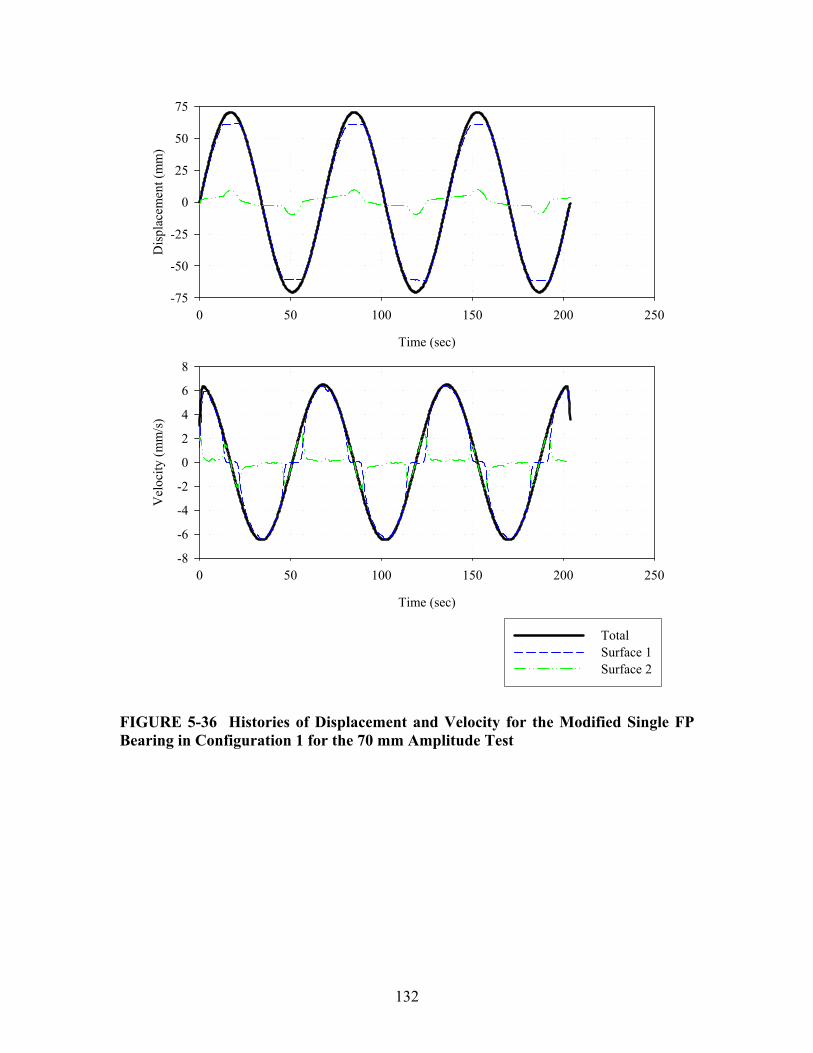
132
Time (sec)
0 50 100 150 200 250
Dis
plac
emen
t (m
m)
-75
-50
-25
0
25
50
75
Time (sec)
0 50 100 150 200 250
Vel
ocity
(mm
/s)
-8
-6
-4
-2
0
2
4
6
8
TotalSurface 1Surface 2
FIGURE 5-36 Histories of Displacement and Velocity for the Modified Single FP Bearing in Configuration 1 for the 70 mm Amplitude Test

133
SECTION 6 CONCLUSIONS
This report has presented a detailed treatment of the mechanical behavior of multi-spherical sliding bearings. The force-displacement relationships of devices with behavior of increasing complexity were determined by extension of the fundamental principles of operation that apply to sliding on a single concave surface. It was shown that each device is capable of exhibiting displacement-dependent adaptive behavior, that is, stiffness and damping which change desirably over the course of motion. These changes are determined only by the relative values of each surface’s coefficient of friction, effective radius of curvature and displacement capacity. Since all are predefined design parameters, (aside from the inherent uncertainty and variability in the coefficient of friction) the behavior is completely controllable by the engineer. Ultimately this is no different than active and semi-active hybrid systems which change their behavior based on predefined control laws. However, the passive devices in presented here have the added advantage of greater reliability and long term-stability of behavior. Working in reverse, it was also shown that in cases in which multiple surfaces are of equal friction, the complexity of behavior exhibited by these devices reduces. For example, it was shown that the double FP with surfaces of equal friction exhibits the same rigid-linear behavior as that of the traditional FP bearing. Also, in the case of the triple FP bearing with inner surfaces of equal friction and outer surfaces of equal friction (that is different from the inner surfaces) the hysteretic behavior collapses to rigid-bilinear. These are important results because they allow engineers to take advantage of the savings in cost afforded by bearings of smaller plan dimension while still being able to use familiar and proven methods of analysis and design. At the time of the writing of this report, all applications of double FP bearing have been in configurations in which
1 2μ = μ (Cathedral of Christ the Light, Oakland, CA) and all applications of triple FP bearing have been in configurations in which 2 3 1 4μ = μ < μ = μ (Mills-Peninsula Hospital, south of San Francisco, CA and less than 2 miles from the San Andreas fault). Likely the majority applications of these devices in the future will be in the simpler configurations of equal friction. However, the effort was made in this report to formulate and explain the behavior for the most general and fully adaptive configurations of each device primarily for two reasons. First, the fact that the behavior for more complex configurations is understood and experimentally verified gives practicing engineers added confidence in implementing these devices in the simpler configurations. Second, the work presented here serves as the foundation upon which more sophisticated models used for dynamic analysis are based. It is imperative that the basic mechanics and principles of operation are well understood prior to the formulation of models incorporating velocity dependence of the coefficient of friction, variable axial force and bidirectional motion. These are needed in order to properly investigate the potential benefits that the adaptive behavior exhibited by these devices may have in terms of both economy of the isolation system and performance of structural and nonstructural components.


135
SECTION 7 REFERENCES
American Association of State Highway and Transportation Officials (1999). “Guide Specifications for Seismic Isolation Design”, AASHTO, Washington DC, USA. American Society of Civil Engineers (2006). “Minimum Design Loads for Buildings and Other Structures”, Standard ASCE/SEI 7-05, ASCE, Reston, VA, USA. Constantinou MC, Mokha AS, Reinhorn AM (1991). “Study of Sliding Bearing and Helical-Steel-Spring Isolation System”, ASCE Journal of Structural Engineering, 117(4), 1257-1275. Constantinou MC, Tsopelas P, Kasalanati A, Wolff ED (1999). “Property Modification Factors for Seismic Isolation Bearings”, Technical Report MCEER-99-0012, Multidisciplinary Center for Earthquake Engineering Research, State University of New York at Buffalo, Buffalo, NY, USA. Constantinou MC, Tsopelas P, Kim YS, Okamoto S (1993). “NCEER-Taisei Corporation Research Program on Sliding Seismic Isolation Systems for Bridges: Experimental and Analytical Study of a Friction Pendulum System (FPS)”, Technical Report NCEER-93-0020, National Center for Earthquake Engineering Research, State University of New York at Buffalo, Buffalo, NY, USA. Constantinou MC (2004). “Friction Pendulum Double Concave Bearing”, NEES report available at: http://nees.buffalo.edu/docs/dec304/FP-DC%20Report-DEMO.pdf. Constantinou MC, Whittaker AS, Kalpakidis Y, Fenz DM, Warn GP (2007a). “Performance of Seismic Isolation Hardware Under Service and Seismic Loading”, Technical Report MCEER-07-0012, Multidisciplinary Center for Earthquake Engineering Research, State University of New York at Buffalo, Buffalo, NY, USA. Constantinou MC, Whittaker AS, Fenz DM, Apostolakis G (2007b). “Seismic Isolation of Bridges: Version 2”, Report to Sponsor: California Department of Transportation. Feng MQ, Shinozuka M, Fujii S (1993). “Friction-Controllable Sliding Isolation System”, ASCE Journal of Engineering Mechanics, 119(9), 1845-1864. Fenz DM, Constantinou MC (2006). “Behavior of the Double Concave Friction Pendulum Bearing”, Earthquake Engineering and Structural Dynamics, 35(11) 1403-1424, DOI: 10.1002/eqe.589.

136
Fenz DM, Constantinou MC (2007a). “Spherical Sliding Isolation Bearings with Adaptive Behavior: Theory”, Earthquake Engineering and Structural Dynamics (in press, available online), DOI: 10.1002/eqe751. Fenz DM, Constantinou MC (2007b). “Modeling Triple Friction Pendulum Bearings for Response History Analysis”, submitted for review and possible publication in Earthquake Spectra. Fenz DM, Constantinou MC (2007c). “Spherical Sliding Isolation Bearings with Adaptive Behavior: Experimental Verification”, Earthquake Engineering and Structural Dynamics (in press, available online), DOI: 10.1002/eqe750. Hall JF (1999). “Discussion of ‘The Role of Damping in Seismic Isolation’”, Earthquake Engineering and Structural Dynamics, 28(12), 1717-1720. Hyakuda T, Saito K, Matsushita T, Tanaka N, Yoneki S, Yasuda M, Miyazaki M, Suzuki A, Sawada T (2001). “The Structural Design and Earthquake Observation of a Seismic Isolation Building Using Friction Pendulum System”, Proceedings, 7th International Seminar on Seismic Isolation, Passive Energy Dissipation and Active Control of Vibrations of Structures, Assisi, Italy. Imbibo M, Kelly JM (1997). “Stability Aspects of Elastomeric Isolators”, Earthquake Spectra, 13(3), 431-449. Kasalanati A, Constantinou MC (1999). “Experimental Study of Bridge Elastomeric and Other Isolation and Energy Dissipation Systems with Emphasis on Uplift Prevention and High Velocity Near Source Seismic Excitation”, Technical Report MCEER-99-0004, Multidisciplinary Center for Earthquake Engineering Research, State University of New York at Buffalo, Buffalo, NY, USA. Kelly JM, Griffith MC, Aiken ID (1987). “A Displacement Control and Uplift Restraint Device for Base Isolated Structures”, Report No. UCB/EERC-88/02, Earthquake Engineering Research Center, University of California Berkeley, Berkeley, CA, USA. Kelly JM (1999). “The Role of Damping in Seismic Isolation”, Earthquake Engineering and Structural Dynamics, 28(1), 3-20. Lin PY, Roschke PN, Loh CH, Cheng CP (2004). “Semi-Active Controlled Base- Isolation System with Magnetorheological Damper and Pendulum System”, Proceedings of the 13th World Conference on Earthquake Engineering, Vancouver, BC, Canada, Paper 691. Mokha A, Constantinou MC, Reinhorn AM (1990). “Teflon Bearings in Base Isolation. I: Testing”, ASCE Journal of Structural Engineering, 116(2), 438-454.

137
Mosqueda G, Whittaker AS, Fenves GL, Mahin SA (2004). “Experimental and Analytical Studies of the Friction Pendulum System for the Seismic Protection of Simple Bridges”, Report No. UCB/EERC-2004-01, Earthquake Engineering Research Center, University of California Berkeley, Berkeley, CA, USA. Nagarajaiah S, Sahasrabudhe S (2006). “Seismic Response Control of Smart Sliding Isolated Buildings Using Variable Stiffness Systems: An Experimental and Numerical Study”, Earthquake Engineering and Structural Dynamics, 35(2), 177- 197, DOI: 10.1002/eqe.514. Pranesh M, Sinha R (2000). “VFPI: An Isolation Device for Aseismic Design”, Earthquake Engineering and Structural Dynamics, 29(5), 603-627. Riley MA, Reinhorn AM, Nagarajaiah S (1998). “Implementation Issues and Testing of a Hybrid Isolation System”, Engineering Structures, 20(3), 144-154. Sumitomo Construction (1990). “Base-Isolated Buildings by Sumitomo Construction”, Report of the R&D Section, Building Dept., Sumitomo Construction Co. Ltd., Tokyo, Japan. Tarics AG (1995). Composite Seismic Isolator and Method, United States Patent Office, Patent No. 5,461,835. Touaillon J (1870). Improvement in Buildings, United States Patent Office, Letters Patent No. 99,973. Tsai CS, Chiang TC, Chen BJ (2003a). “Seismic Behavior of MFPS Isolated Structure Under Near-Fault Earthquakes and Strong Ground Motions with Long Predominant Periods”, Proceedings of the 2003 ASME Pressure Vessels and Piping Conference, Cleveland, OH, USA, vol. 1, pp 73-79. Tsai CS, Chiang TC, Chen BJ (2003b). “Shaking Table Tests of a Full Scale Steel Structure Isolated with MFPS”, Proceedings of the 2003 ASME Pressure Vessels and Piping Conference, Cleveland, OH, USA, vol. 1, pp 41-47. Tsai CS, Chiang TC, Chen BJ (2005). “Experimental Evaluation of Piecewise Exact Solution for Predicting Seismic Responses of Spherical Sliding Type Isolated Structures”, Earthquake Engineering and Structural Dynamics, 34(9), 1027-1046, DOI: 10.1002/eqe.430. Tsai CS, Chen WS, Chiang TC, Chen BJ (2006). “Component and Shaking Table Tests for Full Scale Multiple Friction Pendulum System”, Earthquake Engineering and Structural Dynamics, 35(13), 1653-1675, DOI: 10.1002/eqe.598. Turner, Ward (2007). Personal communication and unpublished engineering calculations.
138
Wongprasert N, Symans MD, (2005). “Experimental Evaluation of Adaptive Elastomeric Base-Isolated Structures Using Variable-Orifice Fluid Dampers”, ASCE Journal of Structural Engineering, 131(6), 867-877, DOI: 10.1061/(ASCE)0733- 9445(2005)131:6(867). Zayas VA, Low SS, Mahin SA (1987). “The FPS Earthquake Resisting System: Experimental Report”, Report No. UCB/EERC-87/01, Earthquake Engineering Research Center, University of California Berkeley, Berkeley, CA, USA. Zayas VA, Low SS, Bozzo L, Mahin SA (1989). “Feasibility and Performance Studies on Improving the Earthquake Resistance of New and Existing Buildings Using the Friction Pendulum System”, Report No. UCB/EERC-89/09, Earthquake Engineering Research Center, University of California Berkeley, Berkeley, CA, USA.
139
MCEER Technical Reports
MCEER publishes technical reports on a variety of subjects written by authors funded through MCEER. These reports are available from both MCEER Publications and the National Technical Information Service (NTIS). Requests for reports should be directed to MCEER Publications, MCEER, University at Buffalo, State University of New York, Red Jacket Quadrangle, Buffalo, New York 14261. Reports can also be requested through NTIS, 5285 Port Royal Road, Springfield, Virginia 22161. NTIS accession numbers are shown in parenthesis, if available. NCEER-87-0001 "First-Year Program in Research, Education and Technology Transfer," 3/5/87, (PB88-134275, A04, MF-
A01). NCEER-87-0002 "Experimental Evaluation of Instantaneous Optimal Algorithms for Structural Control," by R.C. Lin, T.T.
Soong and A.M. Reinhorn, 4/20/87, (PB88-134341, A04, MF-A01). NCEER-87-0003 "Experimentation Using the Earthquake Simulation Facilities at University at Buffalo," by A.M. Reinhorn
and R.L. Ketter, to be published. NCEER-87-0004 "The System Characteristics and Performance of a Shaking Table," by J.S. Hwang, K.C. Chang and G.C.
Lee, 6/1/87, (PB88-134259, A03, MF-A01). This report is available only through NTIS (see address given above).
NCEER-87-0005 "A Finite Element Formulation for Nonlinear Viscoplastic Material Using a Q Model," by O. Gyebi and G.
Dasgupta, 11/2/87, (PB88-213764, A08, MF-A01). NCEER-87-0006 "Symbolic Manipulation Program (SMP) - Algebraic Codes for Two and Three Dimensional Finite Element
Formulations," by X. Lee and G. Dasgupta, 11/9/87, (PB88-218522, A05, MF-A01). NCEER-87-0007 "Instantaneous Optimal Control Laws for Tall Buildings Under Seismic Excitations," by J.N. Yang, A.
Akbarpour and P. Ghaemmaghami, 6/10/87, (PB88-134333, A06, MF-A01). This report is only available through NTIS (see address given above).
NCEER-87-0008 "IDARC: Inelastic Damage Analysis of Reinforced Concrete Frame - Shear-Wall Structures," by Y.J. Park,
A.M. Reinhorn and S.K. Kunnath, 7/20/87, (PB88-134325, A09, MF-A01). This report is only available through NTIS (see address given above).
NCEER-87-0009 "Liquefaction Potential for New York State: A Preliminary Report on Sites in Manhattan and Buffalo," by
M. Budhu, V. Vijayakumar, R.F. Giese and L. Baumgras, 8/31/87, (PB88-163704, A03, MF-A01). This report is available only through NTIS (see address given above).
NCEER-87-0010 "Vertical and Torsional Vibration of Foundations in Inhomogeneous Media," by A.S. Veletsos and K.W.
Dotson, 6/1/87, (PB88-134291, A03, MF-A01). This report is only available through NTIS (see address given above).
NCEER-87-0011 "Seismic Probabilistic Risk Assessment and Seismic Margins Studies for Nuclear Power Plants," by Howard
H.M. Hwang, 6/15/87, (PB88-134267, A03, MF-A01). This report is only available through NTIS (see address given above).
NCEER-87-0012 "Parametric Studies of Frequency Response of Secondary Systems Under Ground-Acceleration Excitations,"
by Y. Yong and Y.K. Lin, 6/10/87, (PB88-134309, A03, MF-A01). This report is only available through NTIS (see address given above).
NCEER-87-0013 "Frequency Response of Secondary Systems Under Seismic Excitation," by J.A. HoLung, J. Cai and Y.K.
Lin, 7/31/87, (PB88-134317, A05, MF-A01). This report is only available through NTIS (see address given above).
NCEER-87-0014 "Modelling Earthquake Ground Motions in Seismically Active Regions Using Parametric Time Series
Methods," by G.W. Ellis and A.S. Cakmak, 8/25/87, (PB88-134283, A08, MF-A01). This report is only available through NTIS (see address given above).
NCEER-87-0015 "Detection and Assessment of Seismic Structural Damage," by E. DiPasquale and A.S. Cakmak, 8/25/87,
(PB88-163712, A05, MF-A01). This report is only available through NTIS (see address given above).
140
NCEER-87-0016 "Pipeline Experiment at Parkfield, California," by J. Isenberg and E. Richardson, 9/15/87, (PB88-163720,
A03, MF-A01). This report is available only through NTIS (see address given above). NCEER-87-0017 "Digital Simulation of Seismic Ground Motion," by M. Shinozuka, G. Deodatis and T. Harada, 8/31/87,
(PB88-155197, A04, MF-A01). This report is available only through NTIS (see address given above). NCEER-87-0018 "Practical Considerations for Structural Control: System Uncertainty, System Time Delay and Truncation of
Small Control Forces," J.N. Yang and A. Akbarpour, 8/10/87, (PB88-163738, A08, MF-A01). This report is only available through NTIS (see address given above).
NCEER-87-0019 "Modal Analysis of Nonclassically Damped Structural Systems Using Canonical Transformation," by J.N.
Yang, S. Sarkani and F.X. Long, 9/27/87, (PB88-187851, A04, MF-A01). NCEER-87-0020 "A Nonstationary Solution in Random Vibration Theory," by J.R. Red-Horse and P.D. Spanos, 11/3/87,
(PB88-163746, A03, MF-A01). NCEER-87-0021 "Horizontal Impedances for Radially Inhomogeneous Viscoelastic Soil Layers," by A.S. Veletsos and K.W.
Dotson, 10/15/87, (PB88-150859, A04, MF-A01). NCEER-87-0022 "Seismic Damage Assessment of Reinforced Concrete Members," by Y.S. Chung, C. Meyer and M.
Shinozuka, 10/9/87, (PB88-150867, A05, MF-A01). This report is available only through NTIS (see address given above).
NCEER-87-0023 "Active Structural Control in Civil Engineering," by T.T. Soong, 11/11/87, (PB88-187778, A03, MF-A01). NCEER-87-0024 "Vertical and Torsional Impedances for Radially Inhomogeneous Viscoelastic Soil Layers," by K.W. Dotson
and A.S. Veletsos, 12/87, (PB88-187786, A03, MF-A01). NCEER-87-0025 "Proceedings from the Symposium on Seismic Hazards, Ground Motions, Soil-Liquefaction and Engineering
Practice in Eastern North America," October 20-22, 1987, edited by K.H. Jacob, 12/87, (PB88-188115, A23, MF-A01). This report is available only through NTIS (see address given above).
NCEER-87-0026 "Report on the Whittier-Narrows, California, Earthquake of October 1, 1987," by J. Pantelic and A.
Reinhorn, 11/87, (PB88-187752, A03, MF-A01). This report is available only through NTIS (see address given above).
NCEER-87-0027 "Design of a Modular Program for Transient Nonlinear Analysis of Large 3-D Building Structures," by S.
Srivastav and J.F. Abel, 12/30/87, (PB88-187950, A05, MF-A01). This report is only available through NTIS (see address given above).
NCEER-87-0028 "Second-Year Program in Research, Education and Technology Transfer," 3/8/88, (PB88-219480, A04, MF-
A01). NCEER-88-0001 "Workshop on Seismic Computer Analysis and Design of Buildings With Interactive Graphics," by W.
McGuire, J.F. Abel and C.H. Conley, 1/18/88, (PB88-187760, A03, MF-A01). This report is only available through NTIS (see address given above).
NCEER-88-0002 "Optimal Control of Nonlinear Flexible Structures," by J.N. Yang, F.X. Long and D. Wong, 1/22/88, (PB88-
213772, A06, MF-A01). NCEER-88-0003 "Substructuring Techniques in the Time Domain for Primary-Secondary Structural Systems," by G.D.
Manolis and G. Juhn, 2/10/88, (PB88-213780, A04, MF-A01). NCEER-88-0004 "Iterative Seismic Analysis of Primary-Secondary Systems," by A. Singhal, L.D. Lutes and P.D. Spanos,
2/23/88, (PB88-213798, A04, MF-A01). NCEER-88-0005 "Stochastic Finite Element Expansion for Random Media," by P.D. Spanos and R. Ghanem, 3/14/88, (PB88-
213806, A03, MF-A01).
141
NCEER-88-0006 "Combining Structural Optimization and Structural Control," by F.Y. Cheng and C.P. Pantelides, 1/10/88, (PB88-213814, A05, MF-A01).
NCEER-88-0007 "Seismic Performance Assessment of Code-Designed Structures," by H.H-M. Hwang, J-W. Jaw and H-J.
Shau, 3/20/88, (PB88-219423, A04, MF-A01). This report is only available through NTIS (see address given above).
NCEER-88-0008 "Reliability Analysis of Code-Designed Structures Under Natural Hazards," by H.H-M. Hwang, H. Ushiba
and M. Shinozuka, 2/29/88, (PB88-229471, A07, MF-A01). This report is only available through NTIS (see address given above).
NCEER-88-0009 "Seismic Fragility Analysis of Shear Wall Structures," by J-W Jaw and H.H-M. Hwang, 4/30/88, (PB89-
102867, A04, MF-A01). NCEER-88-0010 "Base Isolation of a Multi-Story Building Under a Harmonic Ground Motion - A Comparison of
Performances of Various Systems," by F-G Fan, G. Ahmadi and I.G. Tadjbakhsh, 5/18/88, (PB89-122238, A06, MF-A01). This report is only available through NTIS (see address given above).
NCEER-88-0011 "Seismic Floor Response Spectra for a Combined System by Green's Functions," by F.M. Lavelle, L.A.
Bergman and P.D. Spanos, 5/1/88, (PB89-102875, A03, MF-A01). NCEER-88-0012 "A New Solution Technique for Randomly Excited Hysteretic Structures," by G.Q. Cai and Y.K. Lin,
5/16/88, (PB89-102883, A03, MF-A01). NCEER-88-0013 "A Study of Radiation Damping and Soil-Structure Interaction Effects in the Centrifuge," by K. Weissman,
supervised by J.H. Prevost, 5/24/88, (PB89-144703, A06, MF-A01). NCEER-88-0014 "Parameter Identification and Implementation of a Kinematic Plasticity Model for Frictional Soils," by J.H.
Prevost and D.V. Griffiths, to be published. NCEER-88-0015 "Two- and Three- Dimensional Dynamic Finite Element Analyses of the Long Valley Dam," by D.V.
Griffiths and J.H. Prevost, 6/17/88, (PB89-144711, A04, MF-A01). NCEER-88-0016 "Damage Assessment of Reinforced Concrete Structures in Eastern United States," by A.M. Reinhorn, M.J.
Seidel, S.K. Kunnath and Y.J. Park, 6/15/88, (PB89-122220, A04, MF-A01). This report is only available through NTIS (see address given above).
NCEER-88-0017 "Dynamic Compliance of Vertically Loaded Strip Foundations in Multilayered Viscoelastic Soils," by S.
Ahmad and A.S.M. Israil, 6/17/88, (PB89-102891, A04, MF-A01). NCEER-88-0018 "An Experimental Study of Seismic Structural Response With Added Viscoelastic Dampers," by R.C. Lin, Z.
Liang, T.T. Soong and R.H. Zhang, 6/30/88, (PB89-122212, A05, MF-A01). This report is available only through NTIS (see address given above).
NCEER-88-0019 "Experimental Investigation of Primary - Secondary System Interaction," by G.D. Manolis, G. Juhn and
A.M. Reinhorn, 5/27/88, (PB89-122204, A04, MF-A01). NCEER-88-0020 "A Response Spectrum Approach For Analysis of Nonclassically Damped Structures," by J.N. Yang, S.
Sarkani and F.X. Long, 4/22/88, (PB89-102909, A04, MF-A01). NCEER-88-0021 "Seismic Interaction of Structures and Soils: Stochastic Approach," by A.S. Veletsos and A.M. Prasad,
7/21/88, (PB89-122196, A04, MF-A01). This report is only available through NTIS (see address given above).
NCEER-88-0022 "Identification of the Serviceability Limit State and Detection of Seismic Structural Damage," by E.
DiPasquale and A.S. Cakmak, 6/15/88, (PB89-122188, A05, MF-A01). This report is available only through NTIS (see address given above).
NCEER-88-0023 "Multi-Hazard Risk Analysis: Case of a Simple Offshore Structure," by B.K. Bhartia and E.H. Vanmarcke,
7/21/88, (PB89-145213, A05, MF-A01).

142
NCEER-88-0024 "Automated Seismic Design of Reinforced Concrete Buildings," by Y.S. Chung, C. Meyer and M. Shinozuka, 7/5/88, (PB89-122170, A06, MF-A01). This report is available only through NTIS (see address given above).
NCEER-88-0025 "Experimental Study of Active Control of MDOF Structures Under Seismic Excitations," by L.L. Chung,
R.C. Lin, T.T. Soong and A.M. Reinhorn, 7/10/88, (PB89-122600, A04, MF-A01). NCEER-88-0026 "Earthquake Simulation Tests of a Low-Rise Metal Structure," by J.S. Hwang, K.C. Chang, G.C. Lee and
R.L. Ketter, 8/1/88, (PB89-102917, A04, MF-A01). NCEER-88-0027 "Systems Study of Urban Response and Reconstruction Due to Catastrophic Earthquakes," by F. Kozin and
H.K. Zhou, 9/22/88, (PB90-162348, A04, MF-A01). NCEER-88-0028 "Seismic Fragility Analysis of Plane Frame Structures," by H.H-M. Hwang and Y.K. Low, 7/31/88, (PB89-
131445, A06, MF-A01). NCEER-88-0029 "Response Analysis of Stochastic Structures," by A. Kardara, C. Bucher and M. Shinozuka, 9/22/88, (PB89-
174429, A04, MF-A01). NCEER-88-0030 "Nonnormal Accelerations Due to Yielding in a Primary Structure," by D.C.K. Chen and L.D. Lutes,
9/19/88, (PB89-131437, A04, MF-A01). NCEER-88-0031 "Design Approaches for Soil-Structure Interaction," by A.S. Veletsos, A.M. Prasad and Y. Tang, 12/30/88,
(PB89-174437, A03, MF-A01). This report is available only through NTIS (see address given above). NCEER-88-0032 "A Re-evaluation of Design Spectra for Seismic Damage Control," by C.J. Turkstra and A.G. Tallin, 11/7/88,
(PB89-145221, A05, MF-A01). NCEER-88-0033 "The Behavior and Design of Noncontact Lap Splices Subjected to Repeated Inelastic Tensile Loading," by
V.E. Sagan, P. Gergely and R.N. White, 12/8/88, (PB89-163737, A08, MF-A01). NCEER-88-0034 "Seismic Response of Pile Foundations," by S.M. Mamoon, P.K. Banerjee and S. Ahmad, 11/1/88, (PB89-
145239, A04, MF-A01). NCEER-88-0035 "Modeling of R/C Building Structures With Flexible Floor Diaphragms (IDARC2)," by A.M. Reinhorn, S.K.
Kunnath and N. Panahshahi, 9/7/88, (PB89-207153, A07, MF-A01). NCEER-88-0036 "Solution of the Dam-Reservoir Interaction Problem Using a Combination of FEM, BEM with Particular
Integrals, Modal Analysis, and Substructuring," by C-S. Tsai, G.C. Lee and R.L. Ketter, 12/31/88, (PB89-207146, A04, MF-A01).
NCEER-88-0037 "Optimal Placement of Actuators for Structural Control," by F.Y. Cheng and C.P. Pantelides, 8/15/88,
(PB89-162846, A05, MF-A01). NCEER-88-0038 "Teflon Bearings in Aseismic Base Isolation: Experimental Studies and Mathematical Modeling," by A.
Mokha, M.C. Constantinou and A.M. Reinhorn, 12/5/88, (PB89-218457, A10, MF-A01). This report is available only through NTIS (see address given above).
NCEER-88-0039 "Seismic Behavior of Flat Slab High-Rise Buildings in the New York City Area," by P. Weidlinger and M.
Ettouney, 10/15/88, (PB90-145681, A04, MF-A01). NCEER-88-0040 "Evaluation of the Earthquake Resistance of Existing Buildings in New York City," by P. Weidlinger and M.
Ettouney, 10/15/88, to be published. NCEER-88-0041 "Small-Scale Modeling Techniques for Reinforced Concrete Structures Subjected to Seismic Loads," by W.
Kim, A. El-Attar and R.N. White, 11/22/88, (PB89-189625, A05, MF-A01). NCEER-88-0042 "Modeling Strong Ground Motion from Multiple Event Earthquakes," by G.W. Ellis and A.S. Cakmak,
10/15/88, (PB89-174445, A03, MF-A01).

143
NCEER-88-0043 "Nonstationary Models of Seismic Ground Acceleration," by M. Grigoriu, S.E. Ruiz and E. Rosenblueth, 7/15/88, (PB89-189617, A04, MF-A01).
NCEER-88-0044 "SARCF User's Guide: Seismic Analysis of Reinforced Concrete Frames," by Y.S. Chung, C. Meyer and M.
Shinozuka, 11/9/88, (PB89-174452, A08, MF-A01). NCEER-88-0045 "First Expert Panel Meeting on Disaster Research and Planning," edited by J. Pantelic and J. Stoyle, 9/15/88,
(PB89-174460, A05, MF-A01). NCEER-88-0046 "Preliminary Studies of the Effect of Degrading Infill Walls on the Nonlinear Seismic Response of Steel
Frames," by C.Z. Chrysostomou, P. Gergely and J.F. Abel, 12/19/88, (PB89-208383, A05, MF-A01). NCEER-88-0047 "Reinforced Concrete Frame Component Testing Facility - Design, Construction, Instrumentation and
Operation," by S.P. Pessiki, C. Conley, T. Bond, P. Gergely and R.N. White, 12/16/88, (PB89-174478, A04, MF-A01).
NCEER-89-0001 "Effects of Protective Cushion and Soil Compliancy on the Response of Equipment Within a Seismically
Excited Building," by J.A. HoLung, 2/16/89, (PB89-207179, A04, MF-A01). NCEER-89-0002 "Statistical Evaluation of Response Modification Factors for Reinforced Concrete Structures," by H.H-M.
Hwang and J-W. Jaw, 2/17/89, (PB89-207187, A05, MF-A01). NCEER-89-0003 "Hysteretic Columns Under Random Excitation," by G-Q. Cai and Y.K. Lin, 1/9/89, (PB89-196513, A03,
MF-A01). NCEER-89-0004 "Experimental Study of `Elephant Foot Bulge' Instability of Thin-Walled Metal Tanks," by Z-H. Jia and R.L.
Ketter, 2/22/89, (PB89-207195, A03, MF-A01). NCEER-89-0005 "Experiment on Performance of Buried Pipelines Across San Andreas Fault," by J. Isenberg, E. Richardson
and T.D. O'Rourke, 3/10/89, (PB89-218440, A04, MF-A01). This report is available only through NTIS (see address given above).
NCEER-89-0006 "A Knowledge-Based Approach to Structural Design of Earthquake-Resistant Buildings," by M. Subramani,
P. Gergely, C.H. Conley, J.F. Abel and A.H. Zaghw, 1/15/89, (PB89-218465, A06, MF-A01). NCEER-89-0007 "Liquefaction Hazards and Their Effects on Buried Pipelines," by T.D. O'Rourke and P.A. Lane, 2/1/89,
(PB89-218481, A09, MF-A01). NCEER-89-0008 "Fundamentals of System Identification in Structural Dynamics," by H. Imai, C-B. Yun, O. Maruyama and
M. Shinozuka, 1/26/89, (PB89-207211, A04, MF-A01). NCEER-89-0009 "Effects of the 1985 Michoacan Earthquake on Water Systems and Other Buried Lifelines in Mexico," by
A.G. Ayala and M.J. O'Rourke, 3/8/89, (PB89-207229, A06, MF-A01). NCEER-89-R010 "NCEER Bibliography of Earthquake Education Materials," by K.E.K. Ross, Second Revision, 9/1/89,
(PB90-125352, A05, MF-A01). This report is replaced by NCEER-92-0018. NCEER-89-0011 "Inelastic Three-Dimensional Response Analysis of Reinforced Concrete Building Structures (IDARC-3D),
Part I - Modeling," by S.K. Kunnath and A.M. Reinhorn, 4/17/89, (PB90-114612, A07, MF-A01). This report is available only through NTIS (see address given above).
NCEER-89-0012 "Recommended Modifications to ATC-14," by C.D. Poland and J.O. Malley, 4/12/89, (PB90-108648, A15,
MF-A01). NCEER-89-0013 "Repair and Strengthening of Beam-to-Column Connections Subjected to Earthquake Loading," by M.
Corazao and A.J. Durrani, 2/28/89, (PB90-109885, A06, MF-A01). NCEER-89-0014 "Program EXKAL2 for Identification of Structural Dynamic Systems," by O. Maruyama, C-B. Yun, M.
Hoshiya and M. Shinozuka, 5/19/89, (PB90-109877, A09, MF-A01).

144
NCEER-89-0015 "Response of Frames With Bolted Semi-Rigid Connections, Part I - Experimental Study and Analytical Predictions," by P.J. DiCorso, A.M. Reinhorn, J.R. Dickerson, J.B. Radziminski and W.L. Harper, 6/1/89, to be published.
NCEER-89-0016 "ARMA Monte Carlo Simulation in Probabilistic Structural Analysis," by P.D. Spanos and M.P. Mignolet,
7/10/89, (PB90-109893, A03, MF-A01). NCEER-89-P017 "Preliminary Proceedings from the Conference on Disaster Preparedness - The Place of Earthquake
Education in Our Schools," Edited by K.E.K. Ross, 6/23/89, (PB90-108606, A03, MF-A01). NCEER-89-0017 "Proceedings from the Conference on Disaster Preparedness - The Place of Earthquake Education in Our
Schools," Edited by K.E.K. Ross, 12/31/89, (PB90-207895, A012, MF-A02). This report is available only through NTIS (see address given above).
NCEER-89-0018 "Multidimensional Models of Hysteretic Material Behavior for Vibration Analysis of Shape Memory Energy
Absorbing Devices, by E.J. Graesser and F.A. Cozzarelli, 6/7/89, (PB90-164146, A04, MF-A01). NCEER-89-0019 "Nonlinear Dynamic Analysis of Three-Dimensional Base Isolated Structures (3D-BASIS)," by S.
Nagarajaiah, A.M. Reinhorn and M.C. Constantinou, 8/3/89, (PB90-161936, A06, MF-A01). This report has been replaced by NCEER-93-0011.
NCEER-89-0020 "Structural Control Considering Time-Rate of Control Forces and Control Rate Constraints," by F.Y. Cheng
and C.P. Pantelides, 8/3/89, (PB90-120445, A04, MF-A01). NCEER-89-0021 "Subsurface Conditions of Memphis and Shelby County," by K.W. Ng, T-S. Chang and H-H.M. Hwang,
7/26/89, (PB90-120437, A03, MF-A01). NCEER-89-0022 "Seismic Wave Propagation Effects on Straight Jointed Buried Pipelines," by K. Elhmadi and M.J. O'Rourke,
8/24/89, (PB90-162322, A10, MF-A02). NCEER-89-0023 "Workshop on Serviceability Analysis of Water Delivery Systems," edited by M. Grigoriu, 3/6/89, (PB90-
127424, A03, MF-A01). NCEER-89-0024 "Shaking Table Study of a 1/5 Scale Steel Frame Composed of Tapered Members," by K.C. Chang, J.S.
Hwang and G.C. Lee, 9/18/89, (PB90-160169, A04, MF-A01). NCEER-89-0025 "DYNA1D: A Computer Program for Nonlinear Seismic Site Response Analysis - Technical
Documentation," by Jean H. Prevost, 9/14/89, (PB90-161944, A07, MF-A01). This report is available only through NTIS (see address given above).
NCEER-89-0026 "1:4 Scale Model Studies of Active Tendon Systems and Active Mass Dampers for Aseismic Protection," by
A.M. Reinhorn, T.T. Soong, R.C. Lin, Y.P. Yang, Y. Fukao, H. Abe and M. Nakai, 9/15/89, (PB90-173246, A10, MF-A02). This report is available only through NTIS (see address given above).
NCEER-89-0027 "Scattering of Waves by Inclusions in a Nonhomogeneous Elastic Half Space Solved by Boundary Element
Methods," by P.K. Hadley, A. Askar and A.S. Cakmak, 6/15/89, (PB90-145699, A07, MF-A01). NCEER-89-0028 "Statistical Evaluation of Deflection Amplification Factors for Reinforced Concrete Structures," by H.H.M.
Hwang, J-W. Jaw and A.L. Ch'ng, 8/31/89, (PB90-164633, A05, MF-A01). NCEER-89-0029 "Bedrock Accelerations in Memphis Area Due to Large New Madrid Earthquakes," by H.H.M. Hwang,
C.H.S. Chen and G. Yu, 11/7/89, (PB90-162330, A04, MF-A01). NCEER-89-0030 "Seismic Behavior and Response Sensitivity of Secondary Structural Systems," by Y.Q. Chen and T.T.
Soong, 10/23/89, (PB90-164658, A08, MF-A01). NCEER-89-0031 "Random Vibration and Reliability Analysis of Primary-Secondary Structural Systems," by Y. Ibrahim, M.
Grigoriu and T.T. Soong, 11/10/89, (PB90-161951, A04, MF-A01).

145
NCEER-89-0032 "Proceedings from the Second U.S. - Japan Workshop on Liquefaction, Large Ground Deformation and Their Effects on Lifelines, September 26-29, 1989," Edited by T.D. O'Rourke and M. Hamada, 12/1/89, (PB90-209388, A22, MF-A03).
NCEER-89-0033 "Deterministic Model for Seismic Damage Evaluation of Reinforced Concrete Structures," by J.M. Bracci,
A.M. Reinhorn, J.B. Mander and S.K. Kunnath, 9/27/89, (PB91-108803, A06, MF-A01). NCEER-89-0034 "On the Relation Between Local and Global Damage Indices," by E. DiPasquale and A.S. Cakmak, 8/15/89,
(PB90-173865, A05, MF-A01). NCEER-89-0035 "Cyclic Undrained Behavior of Nonplastic and Low Plasticity Silts," by A.J. Walker and H.E. Stewart,
7/26/89, (PB90-183518, A10, MF-A01). NCEER-89-0036 "Liquefaction Potential of Surficial Deposits in the City of Buffalo, New York," by M. Budhu, R. Giese and
L. Baumgrass, 1/17/89, (PB90-208455, A04, MF-A01). NCEER-89-0037 "A Deterministic Assessment of Effects of Ground Motion Incoherence," by A.S. Veletsos and Y. Tang,
7/15/89, (PB90-164294, A03, MF-A01). NCEER-89-0038 "Workshop on Ground Motion Parameters for Seismic Hazard Mapping," July 17-18, 1989, edited by R.V.
Whitman, 12/1/89, (PB90-173923, A04, MF-A01). NCEER-89-0039 "Seismic Effects on Elevated Transit Lines of the New York City Transit Authority," by C.J. Costantino,
C.A. Miller and E. Heymsfield, 12/26/89, (PB90-207887, A06, MF-A01). NCEER-89-0040 "Centrifugal Modeling of Dynamic Soil-Structure Interaction," by K. Weissman, Supervised by J.H. Prevost,
5/10/89, (PB90-207879, A07, MF-A01). NCEER-89-0041 "Linearized Identification of Buildings With Cores for Seismic Vulnerability Assessment," by I-K. Ho and
A.E. Aktan, 11/1/89, (PB90-251943, A07, MF-A01). NCEER-90-0001 "Geotechnical and Lifeline Aspects of the October 17, 1989 Loma Prieta Earthquake in San Francisco," by
T.D. O'Rourke, H.E. Stewart, F.T. Blackburn and T.S. Dickerman, 1/90, (PB90-208596, A05, MF-A01). NCEER-90-0002 "Nonnormal Secondary Response Due to Yielding in a Primary Structure," by D.C.K. Chen and L.D. Lutes,
2/28/90, (PB90-251976, A07, MF-A01). NCEER-90-0003 "Earthquake Education Materials for Grades K-12," by K.E.K. Ross, 4/16/90, (PB91-251984, A05, MF-
A05). This report has been replaced by NCEER-92-0018. NCEER-90-0004 "Catalog of Strong Motion Stations in Eastern North America," by R.W. Busby, 4/3/90, (PB90-251984, A05,
MF-A01). NCEER-90-0005 "NCEER Strong-Motion Data Base: A User Manual for the GeoBase Release (Version 1.0 for the Sun3)," by
P. Friberg and K. Jacob, 3/31/90 (PB90-258062, A04, MF-A01). NCEER-90-0006 "Seismic Hazard Along a Crude Oil Pipeline in the Event of an 1811-1812 Type New Madrid Earthquake,"
by H.H.M. Hwang and C-H.S. Chen, 4/16/90, (PB90-258054, A04, MF-A01). NCEER-90-0007 "Site-Specific Response Spectra for Memphis Sheahan Pumping Station," by H.H.M. Hwang and C.S. Lee,
5/15/90, (PB91-108811, A05, MF-A01). NCEER-90-0008 "Pilot Study on Seismic Vulnerability of Crude Oil Transmission Systems," by T. Ariman, R. Dobry, M.
Grigoriu, F. Kozin, M. O'Rourke, T. O'Rourke and M. Shinozuka, 5/25/90, (PB91-108837, A06, MF-A01). NCEER-90-0009 "A Program to Generate Site Dependent Time Histories: EQGEN," by G.W. Ellis, M. Srinivasan and A.S.
Cakmak, 1/30/90, (PB91-108829, A04, MF-A01). NCEER-90-0010 "Active Isolation for Seismic Protection of Operating Rooms," by M.E. Talbott, Supervised by M.
Shinozuka, 6/8/9, (PB91-110205, A05, MF-A01).

146
NCEER-90-0011 "Program LINEARID for Identification of Linear Structural Dynamic Systems," by C-B. Yun and M. Shinozuka, 6/25/90, (PB91-110312, A08, MF-A01).
NCEER-90-0012 "Two-Dimensional Two-Phase Elasto-Plastic Seismic Response of Earth Dams," by A.N. Yiagos, Supervised
by J.H. Prevost, 6/20/90, (PB91-110197, A13, MF-A02). NCEER-90-0013 "Secondary Systems in Base-Isolated Structures: Experimental Investigation, Stochastic Response and
Stochastic Sensitivity," by G.D. Manolis, G. Juhn, M.C. Constantinou and A.M. Reinhorn, 7/1/90, (PB91-110320, A08, MF-A01).
NCEER-90-0014 "Seismic Behavior of Lightly-Reinforced Concrete Column and Beam-Column Joint Details," by S.P.
Pessiki, C.H. Conley, P. Gergely and R.N. White, 8/22/90, (PB91-108795, A11, MF-A02). NCEER-90-0015 "Two Hybrid Control Systems for Building Structures Under Strong Earthquakes," by J.N. Yang and A.
Danielians, 6/29/90, (PB91-125393, A04, MF-A01). NCEER-90-0016 "Instantaneous Optimal Control with Acceleration and Velocity Feedback," by J.N. Yang and Z. Li, 6/29/90,
(PB91-125401, A03, MF-A01). NCEER-90-0017 "Reconnaissance Report on the Northern Iran Earthquake of June 21, 1990," by M. Mehrain, 10/4/90, (PB91-
125377, A03, MF-A01). NCEER-90-0018 "Evaluation of Liquefaction Potential in Memphis and Shelby County," by T.S. Chang, P.S. Tang, C.S. Lee
and H. Hwang, 8/10/90, (PB91-125427, A09, MF-A01). NCEER-90-0019 "Experimental and Analytical Study of a Combined Sliding Disc Bearing and Helical Steel Spring Isolation
System," by M.C. Constantinou, A.S. Mokha and A.M. Reinhorn, 10/4/90, (PB91-125385, A06, MF-A01). This report is available only through NTIS (see address given above).
NCEER-90-0020 "Experimental Study and Analytical Prediction of Earthquake Response of a Sliding Isolation System with a
Spherical Surface," by A.S. Mokha, M.C. Constantinou and A.M. Reinhorn, 10/11/90, (PB91-125419, A05, MF-A01).
NCEER-90-0021 "Dynamic Interaction Factors for Floating Pile Groups," by G. Gazetas, K. Fan, A. Kaynia and E. Kausel,
9/10/90, (PB91-170381, A05, MF-A01). NCEER-90-0022 "Evaluation of Seismic Damage Indices for Reinforced Concrete Structures," by S. Rodriguez-Gomez and
A.S. Cakmak, 9/30/90, PB91-171322, A06, MF-A01). NCEER-90-0023 "Study of Site Response at a Selected Memphis Site," by H. Desai, S. Ahmad, E.S. Gazetas and M.R. Oh,
10/11/90, (PB91-196857, A03, MF-A01). NCEER-90-0024 "A User's Guide to Strongmo: Version 1.0 of NCEER's Strong-Motion Data Access Tool for PCs and
Terminals," by P.A. Friberg and C.A.T. Susch, 11/15/90, (PB91-171272, A03, MF-A01). NCEER-90-0025 "A Three-Dimensional Analytical Study of Spatial Variability of Seismic Ground Motions," by L-L. Hong
and A.H.-S. Ang, 10/30/90, (PB91-170399, A09, MF-A01). NCEER-90-0026 "MUMOID User's Guide - A Program for the Identification of Modal Parameters," by S. Rodriguez-Gomez
and E. DiPasquale, 9/30/90, (PB91-171298, A04, MF-A01). NCEER-90-0027 "SARCF-II User's Guide - Seismic Analysis of Reinforced Concrete Frames," by S. Rodriguez-Gomez, Y.S.
Chung and C. Meyer, 9/30/90, (PB91-171280, A05, MF-A01). NCEER-90-0028 "Viscous Dampers: Testing, Modeling and Application in Vibration and Seismic Isolation," by N. Makris
and M.C. Constantinou, 12/20/90 (PB91-190561, A06, MF-A01). NCEER-90-0029 "Soil Effects on Earthquake Ground Motions in the Memphis Area," by H. Hwang, C.S. Lee, K.W. Ng and
T.S. Chang, 8/2/90, (PB91-190751, A05, MF-A01).

147
NCEER-91-0001 "Proceedings from the Third Japan-U.S. Workshop on Earthquake Resistant Design of Lifeline Facilities and Countermeasures for Soil Liquefaction, December 17-19, 1990," edited by T.D. O'Rourke and M. Hamada, 2/1/91, (PB91-179259, A99, MF-A04).
NCEER-91-0002 "Physical Space Solutions of Non-Proportionally Damped Systems," by M. Tong, Z. Liang and G.C. Lee,
1/15/91, (PB91-179242, A04, MF-A01). NCEER-91-0003 "Seismic Response of Single Piles and Pile Groups," by K. Fan and G. Gazetas, 1/10/91, (PB92-174994,
A04, MF-A01). NCEER-91-0004 "Damping of Structures: Part 1 - Theory of Complex Damping," by Z. Liang and G. Lee, 10/10/91, (PB92-
197235, A12, MF-A03). NCEER-91-0005 "3D-BASIS - Nonlinear Dynamic Analysis of Three Dimensional Base Isolated Structures: Part II," by S.
Nagarajaiah, A.M. Reinhorn and M.C. Constantinou, 2/28/91, (PB91-190553, A07, MF-A01). This report has been replaced by NCEER-93-0011.
NCEER-91-0006 "A Multidimensional Hysteretic Model for Plasticity Deforming Metals in Energy Absorbing Devices," by
E.J. Graesser and F.A. Cozzarelli, 4/9/91, (PB92-108364, A04, MF-A01). NCEER-91-0007 "A Framework for Customizable Knowledge-Based Expert Systems with an Application to a KBES for
Evaluating the Seismic Resistance of Existing Buildings," by E.G. Ibarra-Anaya and S.J. Fenves, 4/9/91, (PB91-210930, A08, MF-A01).
NCEER-91-0008 "Nonlinear Analysis of Steel Frames with Semi-Rigid Connections Using the Capacity Spectrum Method,"
by G.G. Deierlein, S-H. Hsieh, Y-J. Shen and J.F. Abel, 7/2/91, (PB92-113828, A05, MF-A01). NCEER-91-0009 "Earthquake Education Materials for Grades K-12," by K.E.K. Ross, 4/30/91, (PB91-212142, A06, MF-
A01). This report has been replaced by NCEER-92-0018. NCEER-91-0010 "Phase Wave Velocities and Displacement Phase Differences in a Harmonically Oscillating Pile," by N.
Makris and G. Gazetas, 7/8/91, (PB92-108356, A04, MF-A01). NCEER-91-0011 "Dynamic Characteristics of a Full-Size Five-Story Steel Structure and a 2/5 Scale Model," by K.C. Chang,
G.C. Yao, G.C. Lee, D.S. Hao and Y.C. Yeh," 7/2/91, (PB93-116648, A06, MF-A02). NCEER-91-0012 "Seismic Response of a 2/5 Scale Steel Structure with Added Viscoelastic Dampers," by K.C. Chang, T.T.
Soong, S-T. Oh and M.L. Lai, 5/17/91, (PB92-110816, A05, MF-A01). NCEER-91-0013 "Earthquake Response of Retaining Walls; Full-Scale Testing and Computational Modeling," by S.
Alampalli and A-W.M. Elgamal, 6/20/91, to be published. NCEER-91-0014 "3D-BASIS-M: Nonlinear Dynamic Analysis of Multiple Building Base Isolated Structures," by P.C.
Tsopelas, S. Nagarajaiah, M.C. Constantinou and A.M. Reinhorn, 5/28/91, (PB92-113885, A09, MF-A02). NCEER-91-0015 "Evaluation of SEAOC Design Requirements for Sliding Isolated Structures," by D. Theodossiou and M.C.
Constantinou, 6/10/91, (PB92-114602, A11, MF-A03). NCEER-91-0016 "Closed-Loop Modal Testing of a 27-Story Reinforced Concrete Flat Plate-Core Building," by H.R.
Somaprasad, T. Toksoy, H. Yoshiyuki and A.E. Aktan, 7/15/91, (PB92-129980, A07, MF-A02). NCEER-91-0017 "Shake Table Test of a 1/6 Scale Two-Story Lightly Reinforced Concrete Building," by A.G. El-Attar, R.N.
White and P. Gergely, 2/28/91, (PB92-222447, A06, MF-A02). NCEER-91-0018 "Shake Table Test of a 1/8 Scale Three-Story Lightly Reinforced Concrete Building," by A.G. El-Attar, R.N.
White and P. Gergely, 2/28/91, (PB93-116630, A08, MF-A02). NCEER-91-0019 "Transfer Functions for Rigid Rectangular Foundations," by A.S. Veletsos, A.M. Prasad and W.H. Wu,
7/31/91, to be published.

148
NCEER-91-0020 "Hybrid Control of Seismic-Excited Nonlinear and Inelastic Structural Systems," by J.N. Yang, Z. Li and A. Danielians, 8/1/91, (PB92-143171, A06, MF-A02).
NCEER-91-0021 "The NCEER-91 Earthquake Catalog: Improved Intensity-Based Magnitudes and Recurrence Relations for
U.S. Earthquakes East of New Madrid," by L. Seeber and J.G. Armbruster, 8/28/91, (PB92-176742, A06, MF-A02).
NCEER-91-0022 "Proceedings from the Implementation of Earthquake Planning and Education in Schools: The Need for
Change - The Roles of the Changemakers," by K.E.K. Ross and F. Winslow, 7/23/91, (PB92-129998, A12, MF-A03).
NCEER-91-0023 "A Study of Reliability-Based Criteria for Seismic Design of Reinforced Concrete Frame Buildings," by
H.H.M. Hwang and H-M. Hsu, 8/10/91, (PB92-140235, A09, MF-A02). NCEER-91-0024 "Experimental Verification of a Number of Structural System Identification Algorithms," by R.G. Ghanem,
H. Gavin and M. Shinozuka, 9/18/91, (PB92-176577, A18, MF-A04). NCEER-91-0025 "Probabilistic Evaluation of Liquefaction Potential," by H.H.M. Hwang and C.S. Lee," 11/25/91, (PB92-
143429, A05, MF-A01). NCEER-91-0026 "Instantaneous Optimal Control for Linear, Nonlinear and Hysteretic Structures - Stable Controllers," by J.N.
Yang and Z. Li, 11/15/91, (PB92-163807, A04, MF-A01). NCEER-91-0027 "Experimental and Theoretical Study of a Sliding Isolation System for Bridges," by M.C. Constantinou, A.
Kartoum, A.M. Reinhorn and P. Bradford, 11/15/91, (PB92-176973, A10, MF-A03). NCEER-92-0001 "Case Studies of Liquefaction and Lifeline Performance During Past Earthquakes, Volume 1: Japanese Case
Studies," Edited by M. Hamada and T. O'Rourke, 2/17/92, (PB92-197243, A18, MF-A04). NCEER-92-0002 "Case Studies of Liquefaction and Lifeline Performance During Past Earthquakes, Volume 2: United States
Case Studies," Edited by T. O'Rourke and M. Hamada, 2/17/92, (PB92-197250, A20, MF-A04). NCEER-92-0003 "Issues in Earthquake Education," Edited by K. Ross, 2/3/92, (PB92-222389, A07, MF-A02). NCEER-92-0004 "Proceedings from the First U.S. - Japan Workshop on Earthquake Protective Systems for Bridges," Edited
by I.G. Buckle, 2/4/92, (PB94-142239, A99, MF-A06). NCEER-92-0005 "Seismic Ground Motion from a Haskell-Type Source in a Multiple-Layered Half-Space," A.P. Theoharis, G.
Deodatis and M. Shinozuka, 1/2/92, to be published. NCEER-92-0006 "Proceedings from the Site Effects Workshop," Edited by R. Whitman, 2/29/92, (PB92-197201, A04, MF-
A01). NCEER-92-0007 "Engineering Evaluation of Permanent Ground Deformations Due to Seismically-Induced Liquefaction," by
M.H. Baziar, R. Dobry and A-W.M. Elgamal, 3/24/92, (PB92-222421, A13, MF-A03). NCEER-92-0008 "A Procedure for the Seismic Evaluation of Buildings in the Central and Eastern United States," by C.D.
Poland and J.O. Malley, 4/2/92, (PB92-222439, A20, MF-A04). NCEER-92-0009 "Experimental and Analytical Study of a Hybrid Isolation System Using Friction Controllable Sliding
Bearings," by M.Q. Feng, S. Fujii and M. Shinozuka, 5/15/92, (PB93-150282, A06, MF-A02). NCEER-92-0010 "Seismic Resistance of Slab-Column Connections in Existing Non-Ductile Flat-Plate Buildings," by A.J.
Durrani and Y. Du, 5/18/92, (PB93-116812, A06, MF-A02). NCEER-92-0011 "The Hysteretic and Dynamic Behavior of Brick Masonry Walls Upgraded by Ferrocement Coatings Under
Cyclic Loading and Strong Simulated Ground Motion," by H. Lee and S.P. Prawel, 5/11/92, to be published. NCEER-92-0012 "Study of Wire Rope Systems for Seismic Protection of Equipment in Buildings," by G.F. Demetriades,
M.C. Constantinou and A.M. Reinhorn, 5/20/92, (PB93-116655, A08, MF-A02).
149
NCEER-92-0013 "Shape Memory Structural Dampers: Material Properties, Design and Seismic Testing," by P.R. Witting and F.A. Cozzarelli, 5/26/92, (PB93-116663, A05, MF-A01).
NCEER-92-0014 "Longitudinal Permanent Ground Deformation Effects on Buried Continuous Pipelines," by M.J. O'Rourke,
and C. Nordberg, 6/15/92, (PB93-116671, A08, MF-A02). NCEER-92-0015 "A Simulation Method for Stationary Gaussian Random Functions Based on the Sampling Theorem," by M.
Grigoriu and S. Balopoulou, 6/11/92, (PB93-127496, A05, MF-A01). NCEER-92-0016 "Gravity-Load-Designed Reinforced Concrete Buildings: Seismic Evaluation of Existing Construction and
Detailing Strategies for Improved Seismic Resistance," by G.W. Hoffmann, S.K. Kunnath, A.M. Reinhorn and J.B. Mander, 7/15/92, (PB94-142007, A08, MF-A02).
NCEER-92-0017 "Observations on Water System and Pipeline Performance in the Limón Area of Costa Rica Due to the April
22, 1991 Earthquake," by M. O'Rourke and D. Ballantyne, 6/30/92, (PB93-126811, A06, MF-A02). NCEER-92-0018 "Fourth Edition of Earthquake Education Materials for Grades K-12," Edited by K.E.K. Ross, 8/10/92,
(PB93-114023, A07, MF-A02). NCEER-92-0019 "Proceedings from the Fourth Japan-U.S. Workshop on Earthquake Resistant Design of Lifeline Facilities
and Countermeasures for Soil Liquefaction," Edited by M. Hamada and T.D. O'Rourke, 8/12/92, (PB93-163939, A99, MF-E11).
NCEER-92-0020 "Active Bracing System: A Full Scale Implementation of Active Control," by A.M. Reinhorn, T.T. Soong,
R.C. Lin, M.A. Riley, Y.P. Wang, S. Aizawa and M. Higashino, 8/14/92, (PB93-127512, A06, MF-A02). NCEER-92-0021 "Empirical Analysis of Horizontal Ground Displacement Generated by Liquefaction-Induced Lateral
Spreads," by S.F. Bartlett and T.L. Youd, 8/17/92, (PB93-188241, A06, MF-A02). NCEER-92-0022 "IDARC Version 3.0: Inelastic Damage Analysis of Reinforced Concrete Structures," by S.K. Kunnath, A.M.
Reinhorn and R.F. Lobo, 8/31/92, (PB93-227502, A07, MF-A02). NCEER-92-0023 "A Semi-Empirical Analysis of Strong-Motion Peaks in Terms of Seismic Source, Propagation Path and
Local Site Conditions, by M. Kamiyama, M.J. O'Rourke and R. Flores-Berrones, 9/9/92, (PB93-150266, A08, MF-A02).
NCEER-92-0024 "Seismic Behavior of Reinforced Concrete Frame Structures with Nonductile Details, Part I: Summary of
Experimental Findings of Full Scale Beam-Column Joint Tests," by A. Beres, R.N. White and P. Gergely, 9/30/92, (PB93-227783, A05, MF-A01).
NCEER-92-0025 "Experimental Results of Repaired and Retrofitted Beam-Column Joint Tests in Lightly Reinforced Concrete
Frame Buildings," by A. Beres, S. El-Borgi, R.N. White and P. Gergely, 10/29/92, (PB93-227791, A05, MF-A01).
NCEER-92-0026 "A Generalization of Optimal Control Theory: Linear and Nonlinear Structures," by J.N. Yang, Z. Li and S.
Vongchavalitkul, 11/2/92, (PB93-188621, A05, MF-A01). NCEER-92-0027 "Seismic Resistance of Reinforced Concrete Frame Structures Designed Only for Gravity Loads: Part I -
Design and Properties of a One-Third Scale Model Structure," by J.M. Bracci, A.M. Reinhorn and J.B. Mander, 12/1/92, (PB94-104502, A08, MF-A02).
NCEER-92-0028 "Seismic Resistance of Reinforced Concrete Frame Structures Designed Only for Gravity Loads: Part II -
Experimental Performance of Subassemblages," by L.E. Aycardi, J.B. Mander and A.M. Reinhorn, 12/1/92, (PB94-104510, A08, MF-A02).
NCEER-92-0029 "Seismic Resistance of Reinforced Concrete Frame Structures Designed Only for Gravity Loads: Part III -
Experimental Performance and Analytical Study of a Structural Model," by J.M. Bracci, A.M. Reinhorn and J.B. Mander, 12/1/92, (PB93-227528, A09, MF-A01).

150
NCEER-92-0030 "Evaluation of Seismic Retrofit of Reinforced Concrete Frame Structures: Part I - Experimental Performance of Retrofitted Subassemblages," by D. Choudhuri, J.B. Mander and A.M. Reinhorn, 12/8/92, (PB93-198307, A07, MF-A02).
NCEER-92-0031 "Evaluation of Seismic Retrofit of Reinforced Concrete Frame Structures: Part II - Experimental
Performance and Analytical Study of a Retrofitted Structural Model," by J.M. Bracci, A.M. Reinhorn and J.B. Mander, 12/8/92, (PB93-198315, A09, MF-A03).
NCEER-92-0032 "Experimental and Analytical Investigation of Seismic Response of Structures with Supplemental Fluid
Viscous Dampers," by M.C. Constantinou and M.D. Symans, 12/21/92, (PB93-191435, A10, MF-A03). This report is available only through NTIS (see address given above).
NCEER-92-0033 "Reconnaissance Report on the Cairo, Egypt Earthquake of October 12, 1992," by M. Khater, 12/23/92,
(PB93-188621, A03, MF-A01). NCEER-92-0034 "Low-Level Dynamic Characteristics of Four Tall Flat-Plate Buildings in New York City," by H. Gavin, S.
Yuan, J. Grossman, E. Pekelis and K. Jacob, 12/28/92, (PB93-188217, A07, MF-A02). NCEER-93-0001 "An Experimental Study on the Seismic Performance of Brick-Infilled Steel Frames With and Without
Retrofit," by J.B. Mander, B. Nair, K. Wojtkowski and J. Ma, 1/29/93, (PB93-227510, A07, MF-A02). NCEER-93-0002 "Social Accounting for Disaster Preparedness and Recovery Planning," by S. Cole, E. Pantoja and V. Razak,
2/22/93, (PB94-142114, A12, MF-A03). NCEER-93-0003 "Assessment of 1991 NEHRP Provisions for Nonstructural Components and Recommended Revisions," by
T.T. Soong, G. Chen, Z. Wu, R-H. Zhang and M. Grigoriu, 3/1/93, (PB93-188639, A06, MF-A02). NCEER-93-0004 "Evaluation of Static and Response Spectrum Analysis Procedures of SEAOC/UBC for Seismic Isolated
Structures," by C.W. Winters and M.C. Constantinou, 3/23/93, (PB93-198299, A10, MF-A03). NCEER-93-0005 "Earthquakes in the Northeast - Are We Ignoring the Hazard? A Workshop on Earthquake Science and
Safety for Educators," edited by K.E.K. Ross, 4/2/93, (PB94-103066, A09, MF-A02). NCEER-93-0006 "Inelastic Response of Reinforced Concrete Structures with Viscoelastic Braces," by R.F. Lobo, J.M. Bracci,
K.L. Shen, A.M. Reinhorn and T.T. Soong, 4/5/93, (PB93-227486, A05, MF-A02). NCEER-93-0007 "Seismic Testing of Installation Methods for Computers and Data Processing Equipment," by K. Kosar, T.T.
Soong, K.L. Shen, J.A. HoLung and Y.K. Lin, 4/12/93, (PB93-198299, A07, MF-A02). NCEER-93-0008 "Retrofit of Reinforced Concrete Frames Using Added Dampers," by A. Reinhorn, M. Constantinou and C.
Li, to be published. NCEER-93-0009 "Seismic Behavior and Design Guidelines for Steel Frame Structures with Added Viscoelastic Dampers," by
K.C. Chang, M.L. Lai, T.T. Soong, D.S. Hao and Y.C. Yeh, 5/1/93, (PB94-141959, A07, MF-A02). NCEER-93-0010 "Seismic Performance of Shear-Critical Reinforced Concrete Bridge Piers," by J.B. Mander, S.M. Waheed,
M.T.A. Chaudhary and S.S. Chen, 5/12/93, (PB93-227494, A08, MF-A02). NCEER-93-0011 "3D-BASIS-TABS: Computer Program for Nonlinear Dynamic Analysis of Three Dimensional Base Isolated
Structures," by S. Nagarajaiah, C. Li, A.M. Reinhorn and M.C. Constantinou, 8/2/93, (PB94-141819, A09, MF-A02).
NCEER-93-0012 "Effects of Hydrocarbon Spills from an Oil Pipeline Break on Ground Water," by O.J. Helweg and H.H.M.
Hwang, 8/3/93, (PB94-141942, A06, MF-A02). NCEER-93-0013 "Simplified Procedures for Seismic Design of Nonstructural Components and Assessment of Current Code
Provisions," by M.P. Singh, L.E. Suarez, E.E. Matheu and G.O. Maldonado, 8/4/93, (PB94-141827, A09, MF-A02).
NCEER-93-0014 "An Energy Approach to Seismic Analysis and Design of Secondary Systems," by G. Chen and T.T. Soong,
8/6/93, (PB94-142767, A11, MF-A03).
151
NCEER-93-0015 "Proceedings from School Sites: Becoming Prepared for Earthquakes - Commemorating the Third
Anniversary of the Loma Prieta Earthquake," Edited by F.E. Winslow and K.E.K. Ross, 8/16/93, (PB94-154275, A16, MF-A02).
NCEER-93-0016 "Reconnaissance Report of Damage to Historic Monuments in Cairo, Egypt Following the October 12, 1992
Dahshur Earthquake," by D. Sykora, D. Look, G. Croci, E. Karaesmen and E. Karaesmen, 8/19/93, (PB94-142221, A08, MF-A02).
NCEER-93-0017 "The Island of Guam Earthquake of August 8, 1993," by S.W. Swan and S.K. Harris, 9/30/93, (PB94-
141843, A04, MF-A01). NCEER-93-0018 "Engineering Aspects of the October 12, 1992 Egyptian Earthquake," by A.W. Elgamal, M. Amer, K.
Adalier and A. Abul-Fadl, 10/7/93, (PB94-141983, A05, MF-A01). NCEER-93-0019 "Development of an Earthquake Motion Simulator and its Application in Dynamic Centrifuge Testing," by I.
Krstelj, Supervised by J.H. Prevost, 10/23/93, (PB94-181773, A-10, MF-A03). NCEER-93-0020 "NCEER-Taisei Corporation Research Program on Sliding Seismic Isolation Systems for Bridges:
Experimental and Analytical Study of a Friction Pendulum System (FPS)," by M.C. Constantinou, P. Tsopelas, Y-S. Kim and S. Okamoto, 11/1/93, (PB94-142775, A08, MF-A02).
NCEER-93-0021 "Finite Element Modeling of Elastomeric Seismic Isolation Bearings," by L.J. Billings, Supervised by R.
Shepherd, 11/8/93, to be published. NCEER-93-0022 "Seismic Vulnerability of Equipment in Critical Facilities: Life-Safety and Operational Consequences," by
K. Porter, G.S. Johnson, M.M. Zadeh, C. Scawthorn and S. Eder, 11/24/93, (PB94-181765, A16, MF-A03). NCEER-93-0023 "Hokkaido Nansei-oki, Japan Earthquake of July 12, 1993, by P.I. Yanev and C.R. Scawthorn, 12/23/93,
(PB94-181500, A07, MF-A01). NCEER-94-0001 "An Evaluation of Seismic Serviceability of Water Supply Networks with Application to the San Francisco
Auxiliary Water Supply System," by I. Markov, Supervised by M. Grigoriu and T. O'Rourke, 1/21/94, (PB94-204013, A07, MF-A02).
NCEER-94-0002 "NCEER-Taisei Corporation Research Program on Sliding Seismic Isolation Systems for Bridges:
Experimental and Analytical Study of Systems Consisting of Sliding Bearings, Rubber Restoring Force Devices and Fluid Dampers," Volumes I and II, by P. Tsopelas, S. Okamoto, M.C. Constantinou, D. Ozaki and S. Fujii, 2/4/94, (PB94-181740, A09, MF-A02 and PB94-181757, A12, MF-A03).
NCEER-94-0003 "A Markov Model for Local and Global Damage Indices in Seismic Analysis," by S. Rahman and M.
Grigoriu, 2/18/94, (PB94-206000, A12, MF-A03). NCEER-94-0004 "Proceedings from the NCEER Workshop on Seismic Response of Masonry Infills," edited by D.P. Abrams,
3/1/94, (PB94-180783, A07, MF-A02). NCEER-94-0005 "The Northridge, California Earthquake of January 17, 1994: General Reconnaissance Report," edited by
J.D. Goltz, 3/11/94, (PB94-193943, A10, MF-A03). NCEER-94-0006 "Seismic Energy Based Fatigue Damage Analysis of Bridge Columns: Part I - Evaluation of Seismic
Capacity," by G.A. Chang and J.B. Mander, 3/14/94, (PB94-219185, A11, MF-A03). NCEER-94-0007 "Seismic Isolation of Multi-Story Frame Structures Using Spherical Sliding Isolation Systems," by T.M. Al-
Hussaini, V.A. Zayas and M.C. Constantinou, 3/17/94, (PB94-193745, A09, MF-A02). NCEER-94-0008 "The Northridge, California Earthquake of January 17, 1994: Performance of Highway Bridges," edited by
I.G. Buckle, 3/24/94, (PB94-193851, A06, MF-A02). NCEER-94-0009 "Proceedings of the Third U.S.-Japan Workshop on Earthquake Protective Systems for Bridges," edited by
I.G. Buckle and I. Friedland, 3/31/94, (PB94-195815, A99, MF-A06).

152
NCEER-94-0010 "3D-BASIS-ME: Computer Program for Nonlinear Dynamic Analysis of Seismically Isolated Single and Multiple Structures and Liquid Storage Tanks," by P.C. Tsopelas, M.C. Constantinou and A.M. Reinhorn, 4/12/94, (PB94-204922, A09, MF-A02).
NCEER-94-0011 "The Northridge, California Earthquake of January 17, 1994: Performance of Gas Transmission Pipelines,"
by T.D. O'Rourke and M.C. Palmer, 5/16/94, (PB94-204989, A05, MF-A01). NCEER-94-0012 "Feasibility Study of Replacement Procedures and Earthquake Performance Related to Gas Transmission
Pipelines," by T.D. O'Rourke and M.C. Palmer, 5/25/94, (PB94-206638, A09, MF-A02). NCEER-94-0013 "Seismic Energy Based Fatigue Damage Analysis of Bridge Columns: Part II - Evaluation of Seismic
Demand," by G.A. Chang and J.B. Mander, 6/1/94, (PB95-18106, A08, MF-A02). NCEER-94-0014 "NCEER-Taisei Corporation Research Program on Sliding Seismic Isolation Systems for Bridges:
Experimental and Analytical Study of a System Consisting of Sliding Bearings and Fluid Restoring Force/Damping Devices," by P. Tsopelas and M.C. Constantinou, 6/13/94, (PB94-219144, A10, MF-A03).
NCEER-94-0015 "Generation of Hazard-Consistent Fragility Curves for Seismic Loss Estimation Studies," by H. Hwang and
J-R. Huo, 6/14/94, (PB95-181996, A09, MF-A02). NCEER-94-0016 "Seismic Study of Building Frames with Added Energy-Absorbing Devices," by W.S. Pong, C.S. Tsai and
G.C. Lee, 6/20/94, (PB94-219136, A10, A03). NCEER-94-0017 "Sliding Mode Control for Seismic-Excited Linear and Nonlinear Civil Engineering Structures," by J. Yang,
J. Wu, A. Agrawal and Z. Li, 6/21/94, (PB95-138483, A06, MF-A02). NCEER-94-0018 "3D-BASIS-TABS Version 2.0: Computer Program for Nonlinear Dynamic Analysis of Three Dimensional
Base Isolated Structures," by A.M. Reinhorn, S. Nagarajaiah, M.C. Constantinou, P. Tsopelas and R. Li, 6/22/94, (PB95-182176, A08, MF-A02).
NCEER-94-0019 "Proceedings of the International Workshop on Civil Infrastructure Systems: Application of Intelligent
Systems and Advanced Materials on Bridge Systems," Edited by G.C. Lee and K.C. Chang, 7/18/94, (PB95-252474, A20, MF-A04).
NCEER-94-0020 "Study of Seismic Isolation Systems for Computer Floors," by V. Lambrou and M.C. Constantinou, 7/19/94,
(PB95-138533, A10, MF-A03). NCEER-94-0021 "Proceedings of the U.S.-Italian Workshop on Guidelines for Seismic Evaluation and Rehabilitation of
Unreinforced Masonry Buildings," Edited by D.P. Abrams and G.M. Calvi, 7/20/94, (PB95-138749, A13, MF-A03).
NCEER-94-0022 "NCEER-Taisei Corporation Research Program on Sliding Seismic Isolation Systems for Bridges:
Experimental and Analytical Study of a System Consisting of Lubricated PTFE Sliding Bearings and Mild Steel Dampers," by P. Tsopelas and M.C. Constantinou, 7/22/94, (PB95-182184, A08, MF-A02).
NCEER-94-0023 “Development of Reliability-Based Design Criteria for Buildings Under Seismic Load,” by Y.K. Wen, H.
Hwang and M. Shinozuka, 8/1/94, (PB95-211934, A08, MF-A02). NCEER-94-0024 “Experimental Verification of Acceleration Feedback Control Strategies for an Active Tendon System,” by
S.J. Dyke, B.F. Spencer, Jr., P. Quast, M.K. Sain, D.C. Kaspari, Jr. and T.T. Soong, 8/29/94, (PB95-212320, A05, MF-A01).
NCEER-94-0025 “Seismic Retrofitting Manual for Highway Bridges,” Edited by I.G. Buckle and I.F. Friedland, published by
the Federal Highway Administration (PB95-212676, A15, MF-A03). NCEER-94-0026 “Proceedings from the Fifth U.S.-Japan Workshop on Earthquake Resistant Design of Lifeline Facilities and
Countermeasures Against Soil Liquefaction,” Edited by T.D. O’Rourke and M. Hamada, 11/7/94, (PB95-220802, A99, MF-E08).

153
NCEER-95-0001 “Experimental and Analytical Investigation of Seismic Retrofit of Structures with Supplemental Damping: Part 1 - Fluid Viscous Damping Devices,” by A.M. Reinhorn, C. Li and M.C. Constantinou, 1/3/95, (PB95-266599, A09, MF-A02).
NCEER-95-0002 “Experimental and Analytical Study of Low-Cycle Fatigue Behavior of Semi-Rigid Top-And-Seat Angle
Connections,” by G. Pekcan, J.B. Mander and S.S. Chen, 1/5/95, (PB95-220042, A07, MF-A02). NCEER-95-0003 “NCEER-ATC Joint Study on Fragility of Buildings,” by T. Anagnos, C. Rojahn and A.S. Kiremidjian,
1/20/95, (PB95-220026, A06, MF-A02). NCEER-95-0004 “Nonlinear Control Algorithms for Peak Response Reduction,” by Z. Wu, T.T. Soong, V. Gattulli and R.C.
Lin, 2/16/95, (PB95-220349, A05, MF-A01). NCEER-95-0005 “Pipeline Replacement Feasibility Study: A Methodology for Minimizing Seismic and Corrosion Risks to
Underground Natural Gas Pipelines,” by R.T. Eguchi, H.A. Seligson and D.G. Honegger, 3/2/95, (PB95-252326, A06, MF-A02).
NCEER-95-0006 “Evaluation of Seismic Performance of an 11-Story Frame Building During the 1994 Northridge
Earthquake,” by F. Naeim, R. DiSulio, K. Benuska, A. Reinhorn and C. Li, to be published. NCEER-95-0007 “Prioritization of Bridges for Seismic Retrofitting,” by N. Basöz and A.S. Kiremidjian, 4/24/95, (PB95-
252300, A08, MF-A02). NCEER-95-0008 “Method for Developing Motion Damage Relationships for Reinforced Concrete Frames,” by A. Singhal and
A.S. Kiremidjian, 5/11/95, (PB95-266607, A06, MF-A02). NCEER-95-0009 “Experimental and Analytical Investigation of Seismic Retrofit of Structures with Supplemental Damping:
Part II - Friction Devices,” by C. Li and A.M. Reinhorn, 7/6/95, (PB96-128087, A11, MF-A03). NCEER-95-0010 “Experimental Performance and Analytical Study of a Non-Ductile Reinforced Concrete Frame Structure
Retrofitted with Elastomeric Spring Dampers,” by G. Pekcan, J.B. Mander and S.S. Chen, 7/14/95, (PB96-137161, A08, MF-A02).
NCEER-95-0011 “Development and Experimental Study of Semi-Active Fluid Damping Devices for Seismic Protection of
Structures,” by M.D. Symans and M.C. Constantinou, 8/3/95, (PB96-136940, A23, MF-A04). NCEER-95-0012 “Real-Time Structural Parameter Modification (RSPM): Development of Innervated Structures,” by Z.
Liang, M. Tong and G.C. Lee, 4/11/95, (PB96-137153, A06, MF-A01). NCEER-95-0013 “Experimental and Analytical Investigation of Seismic Retrofit of Structures with Supplemental Damping:
Part III - Viscous Damping Walls,” by A.M. Reinhorn and C. Li, 10/1/95, (PB96-176409, A11, MF-A03). NCEER-95-0014 “Seismic Fragility Analysis of Equipment and Structures in a Memphis Electric Substation,” by J-R. Huo and
H.H.M. Hwang, 8/10/95, (PB96-128087, A09, MF-A02). NCEER-95-0015 “The Hanshin-Awaji Earthquake of January 17, 1995: Performance of Lifelines,” Edited by M. Shinozuka,
11/3/95, (PB96-176383, A15, MF-A03). NCEER-95-0016 “Highway Culvert Performance During Earthquakes,” by T.L. Youd and C.J. Beckman, available as
NCEER-96-0015. NCEER-95-0017 “The Hanshin-Awaji Earthquake of January 17, 1995: Performance of Highway Bridges,” Edited by I.G.
Buckle, 12/1/95, to be published. NCEER-95-0018 “Modeling of Masonry Infill Panels for Structural Analysis,” by A.M. Reinhorn, A. Madan, R.E. Valles, Y.
Reichmann and J.B. Mander, 12/8/95, (PB97-110886, MF-A01, A06). NCEER-95-0019 “Optimal Polynomial Control for Linear and Nonlinear Structures,” by A.K. Agrawal and J.N. Yang,
12/11/95, (PB96-168737, A07, MF-A02).
154
NCEER-95-0020 “Retrofit of Non-Ductile Reinforced Concrete Frames Using Friction Dampers,” by R.S. Rao, P. Gergely and R.N. White, 12/22/95, (PB97-133508, A10, MF-A02).
NCEER-95-0021 “Parametric Results for Seismic Response of Pile-Supported Bridge Bents,” by G. Mylonakis, A. Nikolaou
and G. Gazetas, 12/22/95, (PB97-100242, A12, MF-A03). NCEER-95-0022 “Kinematic Bending Moments in Seismically Stressed Piles,” by A. Nikolaou, G. Mylonakis and G. Gazetas,
12/23/95, (PB97-113914, MF-A03, A13). NCEER-96-0001 “Dynamic Response of Unreinforced Masonry Buildings with Flexible Diaphragms,” by A.C. Costley and
D.P. Abrams,” 10/10/96, (PB97-133573, MF-A03, A15). NCEER-96-0002 “State of the Art Review: Foundations and Retaining Structures,” by I. Po Lam, to be published. NCEER-96-0003 “Ductility of Rectangular Reinforced Concrete Bridge Columns with Moderate Confinement,” by N. Wehbe,
M. Saiidi, D. Sanders and B. Douglas, 11/7/96, (PB97-133557, A06, MF-A02). NCEER-96-0004 “Proceedings of the Long-Span Bridge Seismic Research Workshop,” edited by I.G. Buckle and I.M.
Friedland, to be published. NCEER-96-0005 “Establish Representative Pier Types for Comprehensive Study: Eastern United States,” by J. Kulicki and Z.
Prucz, 5/28/96, (PB98-119217, A07, MF-A02). NCEER-96-0006 “Establish Representative Pier Types for Comprehensive Study: Western United States,” by R. Imbsen, R.A.
Schamber and T.A. Osterkamp, 5/28/96, (PB98-118607, A07, MF-A02). NCEER-96-0007 “Nonlinear Control Techniques for Dynamical Systems with Uncertain Parameters,” by R.G. Ghanem and
M.I. Bujakov, 5/27/96, (PB97-100259, A17, MF-A03). NCEER-96-0008 “Seismic Evaluation of a 30-Year Old Non-Ductile Highway Bridge Pier and Its Retrofit,” by J.B. Mander,
B. Mahmoodzadegan, S. Bhadra and S.S. Chen, 5/31/96, (PB97-110902, MF-A03, A10). NCEER-96-0009 “Seismic Performance of a Model Reinforced Concrete Bridge Pier Before and After Retrofit,” by J.B.
Mander, J.H. Kim and C.A. Ligozio, 5/31/96, (PB97-110910, MF-A02, A10). NCEER-96-0010 “IDARC2D Version 4.0: A Computer Program for the Inelastic Damage Analysis of Buildings,” by R.E.
Valles, A.M. Reinhorn, S.K. Kunnath, C. Li and A. Madan, 6/3/96, (PB97-100234, A17, MF-A03). NCEER-96-0011 “Estimation of the Economic Impact of Multiple Lifeline Disruption: Memphis Light, Gas and Water
Division Case Study,” by S.E. Chang, H.A. Seligson and R.T. Eguchi, 8/16/96, (PB97-133490, A11, MF-A03).
NCEER-96-0012 “Proceedings from the Sixth Japan-U.S. Workshop on Earthquake Resistant Design of Lifeline Facilities and
Countermeasures Against Soil Liquefaction, Edited by M. Hamada and T. O’Rourke, 9/11/96, (PB97-133581, A99, MF-A06).
NCEER-96-0013 “Chemical Hazards, Mitigation and Preparedness in Areas of High Seismic Risk: A Methodology for
Estimating the Risk of Post-Earthquake Hazardous Materials Release,” by H.A. Seligson, R.T. Eguchi, K.J. Tierney and K. Richmond, 11/7/96, (PB97-133565, MF-A02, A08).
NCEER-96-0014 “Response of Steel Bridge Bearings to Reversed Cyclic Loading,” by J.B. Mander, D-K. Kim, S.S. Chen and
G.J. Premus, 11/13/96, (PB97-140735, A12, MF-A03). NCEER-96-0015 “Highway Culvert Performance During Past Earthquakes,” by T.L. Youd and C.J. Beckman, 11/25/96,
(PB97-133532, A06, MF-A01). NCEER-97-0001 “Evaluation, Prevention and Mitigation of Pounding Effects in Building Structures,” by R.E. Valles and
A.M. Reinhorn, 2/20/97, (PB97-159552, A14, MF-A03). NCEER-97-0002 “Seismic Design Criteria for Bridges and Other Highway Structures,” by C. Rojahn, R. Mayes, D.G.
Anderson, J. Clark, J.H. Hom, R.V. Nutt and M.J. O’Rourke, 4/30/97, (PB97-194658, A06, MF-A03).

155
NCEER-97-0003 “Proceedings of the U.S.-Italian Workshop on Seismic Evaluation and Retrofit,” Edited by D.P. Abrams and
G.M. Calvi, 3/19/97, (PB97-194666, A13, MF-A03). NCEER-97-0004 "Investigation of Seismic Response of Buildings with Linear and Nonlinear Fluid Viscous Dampers," by
A.A. Seleemah and M.C. Constantinou, 5/21/97, (PB98-109002, A15, MF-A03). NCEER-97-0005 "Proceedings of the Workshop on Earthquake Engineering Frontiers in Transportation Facilities," edited by
G.C. Lee and I.M. Friedland, 8/29/97, (PB98-128911, A25, MR-A04). NCEER-97-0006 "Cumulative Seismic Damage of Reinforced Concrete Bridge Piers," by S.K. Kunnath, A. El-Bahy, A.
Taylor and W. Stone, 9/2/97, (PB98-108814, A11, MF-A03). NCEER-97-0007 "Structural Details to Accommodate Seismic Movements of Highway Bridges and Retaining Walls," by R.A.
Imbsen, R.A. Schamber, E. Thorkildsen, A. Kartoum, B.T. Martin, T.N. Rosser and J.M. Kulicki, 9/3/97, (PB98-108996, A09, MF-A02).
NCEER-97-0008 "A Method for Earthquake Motion-Damage Relationships with Application to Reinforced Concrete Frames,"
by A. Singhal and A.S. Kiremidjian, 9/10/97, (PB98-108988, A13, MF-A03). NCEER-97-0009 "Seismic Analysis and Design of Bridge Abutments Considering Sliding and Rotation," by K. Fishman and
R. Richards, Jr., 9/15/97, (PB98-108897, A06, MF-A02). NCEER-97-0010 "Proceedings of the FHWA/NCEER Workshop on the National Representation of Seismic Ground Motion
for New and Existing Highway Facilities," edited by I.M. Friedland, M.S. Power and R.L. Mayes, 9/22/97, (PB98-128903, A21, MF-A04).
NCEER-97-0011 "Seismic Analysis for Design or Retrofit of Gravity Bridge Abutments," by K.L. Fishman, R. Richards, Jr.
and R.C. Divito, 10/2/97, (PB98-128937, A08, MF-A02). NCEER-97-0012 "Evaluation of Simplified Methods of Analysis for Yielding Structures," by P. Tsopelas, M.C. Constantinou,
C.A. Kircher and A.S. Whittaker, 10/31/97, (PB98-128929, A10, MF-A03). NCEER-97-0013 "Seismic Design of Bridge Columns Based on Control and Repairability of Damage," by C-T. Cheng and
J.B. Mander, 12/8/97, (PB98-144249, A11, MF-A03). NCEER-97-0014 "Seismic Resistance of Bridge Piers Based on Damage Avoidance Design," by J.B. Mander and C-T. Cheng,
12/10/97, (PB98-144223, A09, MF-A02). NCEER-97-0015 “Seismic Response of Nominally Symmetric Systems with Strength Uncertainty,” by S. Balopoulou and M.
Grigoriu, 12/23/97, (PB98-153422, A11, MF-A03). NCEER-97-0016 “Evaluation of Seismic Retrofit Methods for Reinforced Concrete Bridge Columns,” by T.J. Wipf, F.W.
Klaiber and F.M. Russo, 12/28/97, (PB98-144215, A12, MF-A03). NCEER-97-0017 “Seismic Fragility of Existing Conventional Reinforced Concrete Highway Bridges,” by C.L. Mullen and
A.S. Cakmak, 12/30/97, (PB98-153406, A08, MF-A02). NCEER-97-0018 “Loss Asssessment of Memphis Buildings,” edited by D.P. Abrams and M. Shinozuka, 12/31/97, (PB98-
144231, A13, MF-A03). NCEER-97-0019 “Seismic Evaluation of Frames with Infill Walls Using Quasi-static Experiments,” by K.M. Mosalam, R.N.
White and P. Gergely, 12/31/97, (PB98-153455, A07, MF-A02). NCEER-97-0020 “Seismic Evaluation of Frames with Infill Walls Using Pseudo-dynamic Experiments,” by K.M. Mosalam,
R.N. White and P. Gergely, 12/31/97, (PB98-153430, A07, MF-A02). NCEER-97-0021 “Computational Strategies for Frames with Infill Walls: Discrete and Smeared Crack Analyses and Seismic
Fragility,” by K.M. Mosalam, R.N. White and P. Gergely, 12/31/97, (PB98-153414, A10, MF-A02).
156
NCEER-97-0022 “Proceedings of the NCEER Workshop on Evaluation of Liquefaction Resistance of Soils,” edited by T.L. Youd and I.M. Idriss, 12/31/97, (PB98-155617, A15, MF-A03).
MCEER-98-0001 “Extraction of Nonlinear Hysteretic Properties of Seismically Isolated Bridges from Quick-Release Field
Tests,” by Q. Chen, B.M. Douglas, E.M. Maragakis and I.G. Buckle, 5/26/98, (PB99-118838, A06, MF- A01).
MCEER-98-0002 “Methodologies for Evaluating the Importance of Highway Bridges,” by A. Thomas, S. Eshenaur and J.
Kulicki, 5/29/98, (PB99-118846, A10, MF-A02). MCEER-98-0003 “Capacity Design of Bridge Piers and the Analysis of Overstrength,” by J.B. Mander, A. Dutta and P. Goel,
6/1/98, (PB99-118853, A09, MF-A02). MCEER-98-0004 “Evaluation of Bridge Damage Data from the Loma Prieta and Northridge, California Earthquakes,” by N.
Basoz and A. Kiremidjian, 6/2/98, (PB99-118861, A15, MF-A03). MCEER-98-0005 “Screening Guide for Rapid Assessment of Liquefaction Hazard at Highway Bridge Sites,” by T. L. Youd,
6/16/98, (PB99-118879, A06, not available on microfiche). MCEER-98-0006 “Structural Steel and Steel/Concrete Interface Details for Bridges,” by P. Ritchie, N. Kauhl and J. Kulicki,
7/13/98, (PB99-118945, A06, MF-A01). MCEER-98-0007 “Capacity Design and Fatigue Analysis of Confined Concrete Columns,” by A. Dutta and J.B. Mander,
7/14/98, (PB99-118960, A14, MF-A03). MCEER-98-0008 “Proceedings of the Workshop on Performance Criteria for Telecommunication Services Under Earthquake
Conditions,” edited by A.J. Schiff, 7/15/98, (PB99-118952, A08, MF-A02). MCEER-98-0009 “Fatigue Analysis of Unconfined Concrete Columns,” by J.B. Mander, A. Dutta and J.H. Kim, 9/12/98,
(PB99-123655, A10, MF-A02). MCEER-98-0010 “Centrifuge Modeling of Cyclic Lateral Response of Pile-Cap Systems and Seat-Type Abutments in Dry
Sands,” by A.D. Gadre and R. Dobry, 10/2/98, (PB99-123606, A13, MF-A03). MCEER-98-0011 “IDARC-BRIDGE: A Computational Platform for Seismic Damage Assessment of Bridge Structures,” by
A.M. Reinhorn, V. Simeonov, G. Mylonakis and Y. Reichman, 10/2/98, (PB99-162919, A15, MF-A03). MCEER-98-0012 “Experimental Investigation of the Dynamic Response of Two Bridges Before and After Retrofitting with
Elastomeric Bearings,” by D.A. Wendichansky, S.S. Chen and J.B. Mander, 10/2/98, (PB99-162927, A15, MF-A03).
MCEER-98-0013 “Design Procedures for Hinge Restrainers and Hinge Sear Width for Multiple-Frame Bridges,” by R. Des
Roches and G.L. Fenves, 11/3/98, (PB99-140477, A13, MF-A03). MCEER-98-0014 “Response Modification Factors for Seismically Isolated Bridges,” by M.C. Constantinou and J.K. Quarshie,
11/3/98, (PB99-140485, A14, MF-A03). MCEER-98-0015 “Proceedings of the U.S.-Italy Workshop on Seismic Protective Systems for Bridges,” edited by I.M. Friedland
and M.C. Constantinou, 11/3/98, (PB2000-101711, A22, MF-A04). MCEER-98-0016 “Appropriate Seismic Reliability for Critical Equipment Systems: Recommendations Based on Regional
Analysis of Financial and Life Loss,” by K. Porter, C. Scawthorn, C. Taylor and N. Blais, 11/10/98, (PB99-157265, A08, MF-A02).
MCEER-98-0017 “Proceedings of the U.S. Japan Joint Seminar on Civil Infrastructure Systems Research,” edited by M.
Shinozuka and A. Rose, 11/12/98, (PB99-156713, A16, MF-A03). MCEER-98-0018 “Modeling of Pile Footings and Drilled Shafts for Seismic Design,” by I. PoLam, M. Kapuskar and D.
Chaudhuri, 12/21/98, (PB99-157257, A09, MF-A02).
157
MCEER-99-0001 "Seismic Evaluation of a Masonry Infilled Reinforced Concrete Frame by Pseudodynamic Testing," by S.G. Buonopane and R.N. White, 2/16/99, (PB99-162851, A09, MF-A02).
MCEER-99-0002 "Response History Analysis of Structures with Seismic Isolation and Energy Dissipation Systems:
Verification Examples for Program SAP2000," by J. Scheller and M.C. Constantinou, 2/22/99, (PB99-162869, A08, MF-A02).
MCEER-99-0003 "Experimental Study on the Seismic Design and Retrofit of Bridge Columns Including Axial Load Effects,"
by A. Dutta, T. Kokorina and J.B. Mander, 2/22/99, (PB99-162877, A09, MF-A02). MCEER-99-0004 "Experimental Study of Bridge Elastomeric and Other Isolation and Energy Dissipation Systems with
Emphasis on Uplift Prevention and High Velocity Near-source Seismic Excitation," by A. Kasalanati and M. C. Constantinou, 2/26/99, (PB99-162885, A12, MF-A03).
MCEER-99-0005 "Truss Modeling of Reinforced Concrete Shear-flexure Behavior," by J.H. Kim and J.B. Mander, 3/8/99,
(PB99-163693, A12, MF-A03). MCEER-99-0006 "Experimental Investigation and Computational Modeling of Seismic Response of a 1:4 Scale Model Steel
Structure with a Load Balancing Supplemental Damping System," by G. Pekcan, J.B. Mander and S.S. Chen, 4/2/99, (PB99-162893, A11, MF-A03).
MCEER-99-0007 "Effect of Vertical Ground Motions on the Structural Response of Highway Bridges," by M.R. Button, C.J.
Cronin and R.L. Mayes, 4/10/99, (PB2000-101411, A10, MF-A03). MCEER-99-0008 "Seismic Reliability Assessment of Critical Facilities: A Handbook, Supporting Documentation, and Model
Code Provisions," by G.S. Johnson, R.E. Sheppard, M.D. Quilici, S.J. Eder and C.R. Scawthorn, 4/12/99, (PB2000-101701, A18, MF-A04).
MCEER-99-0009 "Impact Assessment of Selected MCEER Highway Project Research on the Seismic Design of Highway
Structures," by C. Rojahn, R. Mayes, D.G. Anderson, J.H. Clark, D'Appolonia Engineering, S. Gloyd and R.V. Nutt, 4/14/99, (PB99-162901, A10, MF-A02).
MCEER-99-0010 "Site Factors and Site Categories in Seismic Codes," by R. Dobry, R. Ramos and M.S. Power, 7/19/99,
(PB2000-101705, A08, MF-A02). MCEER-99-0011 "Restrainer Design Procedures for Multi-Span Simply-Supported Bridges," by M.J. Randall, M. Saiidi, E.
Maragakis and T. Isakovic, 7/20/99, (PB2000-101702, A10, MF-A02). MCEER-99-0012 "Property Modification Factors for Seismic Isolation Bearings," by M.C. Constantinou, P. Tsopelas, A.
Kasalanati and E. Wolff, 7/20/99, (PB2000-103387, A11, MF-A03). MCEER-99-0013 "Critical Seismic Issues for Existing Steel Bridges," by P. Ritchie, N. Kauhl and J. Kulicki, 7/20/99,
(PB2000-101697, A09, MF-A02). MCEER-99-0014 "Nonstructural Damage Database," by A. Kao, T.T. Soong and A. Vender, 7/24/99, (PB2000-101407, A06,
MF-A01). MCEER-99-0015 "Guide to Remedial Measures for Liquefaction Mitigation at Existing Highway Bridge Sites," by H.G.
Cooke and J. K. Mitchell, 7/26/99, (PB2000-101703, A11, MF-A03). MCEER-99-0016 "Proceedings of the MCEER Workshop on Ground Motion Methodologies for the Eastern United States,"
edited by N. Abrahamson and A. Becker, 8/11/99, (PB2000-103385, A07, MF-A02). MCEER-99-0017 "Quindío, Colombia Earthquake of January 25, 1999: Reconnaissance Report," by A.P. Asfura and P.J.
Flores, 10/4/99, (PB2000-106893, A06, MF-A01). MCEER-99-0018 "Hysteretic Models for Cyclic Behavior of Deteriorating Inelastic Structures," by M.V. Sivaselvan and A.M.
Reinhorn, 11/5/99, (PB2000-103386, A08, MF-A02).

158
MCEER-99-0019 "Proceedings of the 7th U.S.- Japan Workshop on Earthquake Resistant Design of Lifeline Facilities and Countermeasures Against Soil Liquefaction," edited by T.D. O'Rourke, J.P. Bardet and M. Hamada, 11/19/99, (PB2000-103354, A99, MF-A06).
MCEER-99-0020 "Development of Measurement Capability for Micro-Vibration Evaluations with Application to Chip
Fabrication Facilities," by G.C. Lee, Z. Liang, J.W. Song, J.D. Shen and W.C. Liu, 12/1/99, (PB2000-105993, A08, MF-A02).
MCEER-99-0021 "Design and Retrofit Methodology for Building Structures with Supplemental Energy Dissipating Systems,"
by G. Pekcan, J.B. Mander and S.S. Chen, 12/31/99, (PB2000-105994, A11, MF-A03). MCEER-00-0001 "The Marmara, Turkey Earthquake of August 17, 1999: Reconnaissance Report," edited by C. Scawthorn;
with major contributions by M. Bruneau, R. Eguchi, T. Holzer, G. Johnson, J. Mander, J. Mitchell, W. Mitchell, A. Papageorgiou, C. Scaethorn, and G. Webb, 3/23/00, (PB2000-106200, A11, MF-A03).
MCEER-00-0002 "Proceedings of the MCEER Workshop for Seismic Hazard Mitigation of Health Care Facilities," edited by
G.C. Lee, M. Ettouney, M. Grigoriu, J. Hauer and J. Nigg, 3/29/00, (PB2000-106892, A08, MF-A02). MCEER-00-0003 "The Chi-Chi, Taiwan Earthquake of September 21, 1999: Reconnaissance Report," edited by G.C. Lee and
C.H. Loh, with major contributions by G.C. Lee, M. Bruneau, I.G. Buckle, S.E. Chang, P.J. Flores, T.D. O'Rourke, M. Shinozuka, T.T. Soong, C-H. Loh, K-C. Chang, Z-J. Chen, J-S. Hwang, M-L. Lin, G-Y. Liu, K-C. Tsai, G.C. Yao and C-L. Yen, 4/30/00, (PB2001-100980, A10, MF-A02).
MCEER-00-0004 "Seismic Retrofit of End-Sway Frames of Steel Deck-Truss Bridges with a Supplemental Tendon System:
Experimental and Analytical Investigation," by G. Pekcan, J.B. Mander and S.S. Chen, 7/1/00, (PB2001-100982, A10, MF-A02).
MCEER-00-0005 "Sliding Fragility of Unrestrained Equipment in Critical Facilities," by W.H. Chong and T.T. Soong, 7/5/00,
(PB2001-100983, A08, MF-A02). MCEER-00-0006 "Seismic Response of Reinforced Concrete Bridge Pier Walls in the Weak Direction," by N. Abo-Shadi, M.
Saiidi and D. Sanders, 7/17/00, (PB2001-100981, A17, MF-A03). MCEER-00-0007 "Low-Cycle Fatigue Behavior of Longitudinal Reinforcement in Reinforced Concrete Bridge Columns," by
J. Brown and S.K. Kunnath, 7/23/00, (PB2001-104392, A08, MF-A02). MCEER-00-0008 "Soil Structure Interaction of Bridges for Seismic Analysis," I. PoLam and H. Law, 9/25/00, (PB2001-
105397, A08, MF-A02). MCEER-00-0009 "Proceedings of the First MCEER Workshop on Mitigation of Earthquake Disaster by Advanced
Technologies (MEDAT-1), edited by M. Shinozuka, D.J. Inman and T.D. O'Rourke, 11/10/00, (PB2001-105399, A14, MF-A03).
MCEER-00-0010 "Development and Evaluation of Simplified Procedures for Analysis and Design of Buildings with Passive
Energy Dissipation Systems, Revision 01," by O.M. Ramirez, M.C. Constantinou, C.A. Kircher, A.S. Whittaker, M.W. Johnson, J.D. Gomez and C. Chrysostomou, 11/16/01, (PB2001-105523, A23, MF-A04).
MCEER-00-0011 "Dynamic Soil-Foundation-Structure Interaction Analyses of Large Caissons," by C-Y. Chang, C-M. Mok,
Z-L. Wang, R. Settgast, F. Waggoner, M.A. Ketchum, H.M. Gonnermann and C-C. Chin, 12/30/00, (PB2001-104373, A07, MF-A02).
MCEER-00-0012 "Experimental Evaluation of Seismic Performance of Bridge Restrainers," by A.G. Vlassis, E.M. Maragakis
and M. Saiid Saiidi, 12/30/00, (PB2001-104354, A09, MF-A02). MCEER-00-0013 "Effect of Spatial Variation of Ground Motion on Highway Structures," by M. Shinozuka, V. Saxena and G.
Deodatis, 12/31/00, (PB2001-108755, A13, MF-A03). MCEER-00-0014 "A Risk-Based Methodology for Assessing the Seismic Performance of Highway Systems," by S.D. Werner,
C.E. Taylor, J.E. Moore, II, J.S. Walton and S. Cho, 12/31/00, (PB2001-108756, A14, MF-A03).

159
MCEER-01-0001 “Experimental Investigation of P-Delta Effects to Collapse During Earthquakes,” by D. Vian and M. Bruneau, 6/25/01, (PB2002-100534, A17, MF-A03).
MCEER-01-0002 “Proceedings of the Second MCEER Workshop on Mitigation of Earthquake Disaster by Advanced
Technologies (MEDAT-2),” edited by M. Bruneau and D.J. Inman, 7/23/01, (PB2002-100434, A16, MF-A03).
MCEER-01-0003 “Sensitivity Analysis of Dynamic Systems Subjected to Seismic Loads,” by C. Roth and M. Grigoriu,
9/18/01, (PB2003-100884, A12, MF-A03). MCEER-01-0004 “Overcoming Obstacles to Implementing Earthquake Hazard Mitigation Policies: Stage 1 Report,” by D.J.
Alesch and W.J. Petak, 12/17/01, (PB2002-107949, A07, MF-A02). MCEER-01-0005 “Updating Real-Time Earthquake Loss Estimates: Methods, Problems and Insights,” by C.E. Taylor, S.E.
Chang and R.T. Eguchi, 12/17/01, (PB2002-107948, A05, MF-A01). MCEER-01-0006 “Experimental Investigation and Retrofit of Steel Pile Foundations and Pile Bents Under Cyclic Lateral
Loadings,” by A. Shama, J. Mander, B. Blabac and S. Chen, 12/31/01, (PB2002-107950, A13, MF-A03). MCEER-02-0001 “Assessment of Performance of Bolu Viaduct in the 1999 Duzce Earthquake in Turkey” by P.C. Roussis,
M.C. Constantinou, M. Erdik, E. Durukal and M. Dicleli, 5/8/02, (PB2003-100883, A08, MF-A02). MCEER-02-0002 “Seismic Behavior of Rail Counterweight Systems of Elevators in Buildings,” by M.P. Singh, Rildova and
L.E. Suarez, 5/27/02. (PB2003-100882, A11, MF-A03). MCEER-02-0003 “Development of Analysis and Design Procedures for Spread Footings,” by G. Mylonakis, G. Gazetas, S.
Nikolaou and A. Chauncey, 10/02/02, (PB2004-101636, A13, MF-A03, CD-A13). MCEER-02-0004 “Bare-Earth Algorithms for Use with SAR and LIDAR Digital Elevation Models,” by C.K. Huyck, R.T.
Eguchi and B. Houshmand, 10/16/02, (PB2004-101637, A07, CD-A07). MCEER-02-0005 “Review of Energy Dissipation of Compression Members in Concentrically Braced Frames,” by K.Lee and
M. Bruneau, 10/18/02, (PB2004-101638, A10, CD-A10). MCEER-03-0001 “Experimental Investigation of Light-Gauge Steel Plate Shear Walls for the Seismic Retrofit of Buildings”
by J. Berman and M. Bruneau, 5/2/03, (PB2004-101622, A10, MF-A03, CD-A10).
MCEER-03-0002 “Statistical Analysis of Fragility Curves,” by M. Shinozuka, M.Q. Feng, H. Kim, T. Uzawa and T. Ueda, 6/16/03, (PB2004-101849, A09, CD-A09).
MCEER-03-0003 “Proceedings of the Eighth U.S.-Japan Workshop on Earthquake Resistant Design f Lifeline Facilities and
Countermeasures Against Liquefaction,” edited by M. Hamada, J.P. Bardet and T.D. O’Rourke, 6/30/03, (PB2004-104386, A99, CD-A99).
MCEER-03-0004 “Proceedings of the PRC-US Workshop on Seismic Analysis and Design of Special Bridges,” edited by L.C.
Fan and G.C. Lee, 7/15/03, (PB2004-104387, A14, CD-A14). MCEER-03-0005 “Urban Disaster Recovery: A Framework and Simulation Model,” by S.B. Miles and S.E. Chang, 7/25/03,
(PB2004-104388, A07, CD-A07). MCEER-03-0006 “Behavior of Underground Piping Joints Due to Static and Dynamic Loading,” by R.D. Meis, M. Maragakis
and R. Siddharthan, 11/17/03, (PB2005-102194, A13, MF-A03, CD-A00). MCEER-03-0007 “Seismic Vulnerability of Timber Bridges and Timber Substructures,” by A.A. Shama, J.B. Mander, I.M.
Friedland and D.R. Allicock, 12/15/03. MCEER-04-0001 “Experimental Study of Seismic Isolation Systems with Emphasis on Secondary System Response and
Verification of Accuracy of Dynamic Response History Analysis Methods,” by E. Wolff and M. Constantinou, 1/16/04 (PB2005-102195, A99, MF-E08, CD-A00).
160
MCEER-04-0002 “Tension, Compression and Cyclic Testing of Engineered Cementitious Composite Materials,” by K. Kesner and S.L. Billington, 3/1/04, (PB2005-102196, A08, CD-A08).
MCEER-04-0003 “Cyclic Testing of Braces Laterally Restrained by Steel Studs to Enhance Performance During Earthquakes,”
by O.C. Celik, J.W. Berman and M. Bruneau, 3/16/04, (PB2005-102197, A13, MF-A03, CD-A00). MCEER-04-0004 “Methodologies for Post Earthquake Building Damage Detection Using SAR and Optical Remote Sensing:
Application to the August 17, 1999 Marmara, Turkey Earthquake,” by C.K. Huyck, B.J. Adams, S. Cho, R.T. Eguchi, B. Mansouri and B. Houshmand, 6/15/04, (PB2005-104888, A10, CD-A00).
MCEER-04-0005 “Nonlinear Structural Analysis Towards Collapse Simulation: A Dynamical Systems Approach,” by M.V.
Sivaselvan and A.M. Reinhorn, 6/16/04, (PB2005-104889, A11, MF-A03, CD-A00). MCEER-04-0006 “Proceedings of the Second PRC-US Workshop on Seismic Analysis and Design of Special Bridges,” edited
by G.C. Lee and L.C. Fan, 6/25/04, (PB2005-104890, A16, CD-A00). MCEER-04-0007 “Seismic Vulnerability Evaluation of Axially Loaded Steel Built-up Laced Members,” by K. Lee and M.
Bruneau, 6/30/04, (PB2005-104891, A16, CD-A00). MCEER-04-0008 “Evaluation of Accuracy of Simplified Methods of Analysis and Design of Buildings with Damping Systems
for Near-Fault and for Soft-Soil Seismic Motions,” by E.A. Pavlou and M.C. Constantinou, 8/16/04, (PB2005-104892, A08, MF-A02, CD-A00).
MCEER-04-0009 “Assessment of Geotechnical Issues in Acute Care Facilities in California,” by M. Lew, T.D. O’Rourke, R.
Dobry and M. Koch, 9/15/04, (PB2005-104893, A08, CD-A00). MCEER-04-0010 “Scissor-Jack-Damper Energy Dissipation System,” by A.N. Sigaher-Boyle and M.C. Constantinou, 12/1/04
(PB2005-108221). MCEER-04-0011 “Seismic Retrofit of Bridge Steel Truss Piers Using a Controlled Rocking Approach,” by M. Pollino and M.
Bruneau, 12/20/04 (PB2006-105795). MCEER-05-0001 “Experimental and Analytical Studies of Structures Seismically Isolated with an Uplift-Restraint Isolation
System,” by P.C. Roussis and M.C. Constantinou, 1/10/05 (PB2005-108222). MCEER-05-0002 “A Versatile Experimentation Model for Study of Structures Near Collapse Applied to Seismic Evaluation of
Irregular Structures,” by D. Kusumastuti, A.M. Reinhorn and A. Rutenberg, 3/31/05 (PB2006-101523). MCEER-05-0003 “Proceedings of the Third PRC-US Workshop on Seismic Analysis and Design of Special Bridges,” edited
by L.C. Fan and G.C. Lee, 4/20/05, (PB2006-105796). MCEER-05-0004 “Approaches for the Seismic Retrofit of Braced Steel Bridge Piers and Proof-of-Concept Testing of an
Eccentrically Braced Frame with Tubular Link,” by J.W. Berman and M. Bruneau, 4/21/05 (PB2006-101524).
MCEER-05-0005 “Simulation of Strong Ground Motions for Seismic Fragility Evaluation of Nonstructural Components in
Hospitals,” by A. Wanitkorkul and A. Filiatrault, 5/26/05 (PB2006-500027). MCEER-05-0006 “Seismic Safety in California Hospitals: Assessing an Attempt to Accelerate the Replacement or Seismic
Retrofit of Older Hospital Facilities,” by D.J. Alesch, L.A. Arendt and W.J. Petak, 6/6/05 (PB2006-105794). MCEER-05-0007 “Development of Seismic Strengthening and Retrofit Strategies for Critical Facilities Using Engineered
Cementitious Composite Materials,” by K. Kesner and S.L. Billington, 8/29/05 (PB2006-111701). MCEER-05-0008 “Experimental and Analytical Studies of Base Isolation Systems for Seismic Protection of Power
Transformers,” by N. Murota, M.Q. Feng and G-Y. Liu, 9/30/05 (PB2006-111702). MCEER-05-0009 “3D-BASIS-ME-MB: Computer Program for Nonlinear Dynamic Analysis of Seismically Isolated
Structures,” by P.C. Tsopelas, P.C. Roussis, M.C. Constantinou, R. Buchanan and A.M. Reinhorn, 10/3/05 (PB2006-111703).
161
MCEER-05-0010 “Steel Plate Shear Walls for Seismic Design and Retrofit of Building Structures,” by D. Vian and M. Bruneau, 12/15/05 (PB2006-111704).
MCEER-05-0011 “The Performance-Based Design Paradigm,” by M.J. Astrella and A. Whittaker, 12/15/05 (PB2006-111705). MCEER-06-0001 “Seismic Fragility of Suspended Ceiling Systems,” H. Badillo-Almaraz, A.S. Whittaker, A.M. Reinhorn and
G.P. Cimellaro, 2/4/06 (PB2006-111706). MCEER-06-0002 “Multi-Dimensional Fragility of Structures,” by G.P. Cimellaro, A.M. Reinhorn and M. Bruneau, 3/1/06
(PB2007-106974, A09, MF-A02, CD A00). MCEER-06-0003 “Built-Up Shear Links as Energy Dissipators for Seismic Protection of Bridges,” by P. Dusicka, A.M. Itani
and I.G. Buckle, 3/15/06 (PB2006-111708). MCEER-06-0004 “Analytical Investigation of the Structural Fuse Concept,” by R.E. Vargas and M. Bruneau, 3/16/06
(PB2006-111709). MCEER-06-0005 “Experimental Investigation of the Structural Fuse Concept,” by R.E. Vargas and M. Bruneau, 3/17/06
(PB2006-111710). MCEER-06-0006 “Further Development of Tubular Eccentrically Braced Frame Links for the Seismic Retrofit of Braced Steel
Truss Bridge Piers,” by J.W. Berman and M. Bruneau, 3/27/06 (PB2007-105147). MCEER-06-0007 “REDARS Validation Report,” by S. Cho, C.K. Huyck, S. Ghosh and R.T. Eguchi, 8/8/06 (PB2007-106983). MCEER-06-0008 “Review of Current NDE Technologies for Post-Earthquake Assessment of Retrofitted Bridge Columns,” by
J.W. Song, Z. Liang and G.C. Lee, 8/21/06 06 (PB2007-106984). MCEER-06-0009 “Liquefaction Remediation in Silty Soils Using Dynamic Compaction and Stone Columns,” by S.
Thevanayagam, G.R. Martin, R. Nashed, T. Shenthan, T. Kanagalingam and N. Ecemis, 8/28/06 06 (PB2007-106985).
MCEER-06-0010 “Conceptual Design and Experimental Investigation of Polymer Matrix Composite Infill Panels for Seismic
Retrofitting,” by W. Jung, M. Chiewanichakorn and A.J. Aref, 9/21/06 (PB2007-106986). MCEER-06-0011 “A Study of the Coupled Horizontal-Vertical Behavior of Elastomeric and Lead-Rubber Seismic Isolation
Bearings,” by G.P. Warn and A.S. Whittaker, 9/22/06 (PB2007-108679). MCEER-06-0012 “Proceedings of the Fourth PRC-US Workshop on Seismic Analysis and Design of Special Bridges:
Advancing Bridge Technologies in Research, Design, Construction and Preservation,” Edited by L.C. Fan, G.C. Lee and L. Ziang, 10/12/06 (PB2007-109042).
MCEER-06-0013 “Cyclic Response and Low Cycle Fatigue Characteristics of Plate Steels,” by P. Dusicka, A.M. Itani and I.G.
Buckle, 11/1/06 06 (PB2007-106987). MCEER-06-0014 “Proceedings of the Second US-Taiwan Bridge Engineering Workshop,” edited by W.P. Yen, J. Shen, J-Y.
Chen and M. Wang, 11/15/06. MCEER-06-0015 “User Manual and Technical Documentation for the REDARSTM Import Wizard,” by S. Cho, S. Ghosh, C.K.
Huyck and S.D. Werner, 11/30/06 (PB2007-114766). MCEER-06-0016 “Hazard Mitigation Strategy and Monitoring Technologies for Urban and Infrastructure Public Buildings:
Proceedings of the China-US Workshops,” edited by X.Y. Zhou, A.L. Zhang, G.C. Lee and M. Tong, 12/12/06 (PB2008-500018).
MCEER-07-0001 “Static and Kinetic Coefficients of Friction for Rigid Blocks,” by C. Kafali, S. Fathali, M. Grigoriu and A.S.
Whittaker, 3/20/07 (PB2007-114767). MCEER-07-0002 “Hazard Mitigation Investment Decision Making: Organizational Response to Legislative Mandate,” by L.A.
Arendt, D.J. Alesch and W.J. Petak, 4/9/07 (PB2007-114768).

162
MCEER-07-0003 “Seismic Behavior of Bidirectional-Resistant Ductile End Diaphragms with Unbonded Braces in Straight or Skewed Steel Bridges,” by O. Celik and M. Bruneau, 4/11/07 (PB2008-105141).
MCEER-07-0004 “Modeling Pile Behavior in Large Pile Groups Under Lateral Loading,” by A.M. Dodds and G.R. Martin,
4/16/07(PB2008-105142). MCEER-07-0005 “Experimental Investigation of Blast Performance of Seismically Resistant Concrete-Filled Steel Tube
Bridge Piers,” by S. Fujikura, M. Bruneau and D. Lopez-Garcia, 4/20/07 (PB2008-105143). MCEER-07-0006 “Seismic Analysis of Conventional and Isolated Liquefied Natural Gas Tanks Using Mechanical Analogs,”
by I.P. Christovasilis and A.S. Whittaker, 5/1/07. MCEER-07-0007 “Experimental Seismic Performance Evaluation of Isolation/Restraint Systems for Mechanical Equipment –
Part 1: Heavy Equipment Study,” by S. Fathali and A. Filiatrault, 6/6/07 (PB2008-105144). MCEER-07-0008 “Seismic Vulnerability of Timber Bridges and Timber Substructures,” by A.A. Sharma, J.B. Mander, I.M.
Friedland and D.R. Allicock, 6/7/07 (PB2008-105145). MCEER-07-0009 “Experimental and Analytical Study of the XY-Friction Pendulum (XY-FP) Bearing for Bridge
Applications,” by C.C. Marin-Artieda, A.S. Whittaker and M.C. Constantinou, 6/7/07 (PB2008-105191). MCEER-07-0010 “Proceedings of the PRC-US Earthquake Engineering Forum for Young Researchers,” Edited by G.C. Lee
and X.Z. Qi, 6/8/07. MCEER-07-0011 “Design Recommendations for Perforated Steel Plate Shear Walls,” by R. Purba and M. Bruneau, 6/18/07,
(PB2008-105192). MCEER-07-0012 “Performance of Seismic Isolation Hardware Under Service and Seismic Loading,” by M.C. Constantinou,
A.S. Whittaker, Y. Kalpakidis, D.M. Fenz and G.P. Warn, 8/27/07, (PB2008-105193). MCEER-07-0013 “Experimental Evaluation of the Seismic Performance of Hospital Piping Subassemblies,” by E.R. Goodwin,
E. Maragakis and A.M. Itani, 9/4/07, (PB2008-105194). MCEER-07-0014 “A Simulation Model of Urban Disaster Recovery and Resilience: Implementation for the 1994 Northridge
Earthquake,” by S. Miles and S.E. Chang, 9/7/07, (PB2008-106426). MCEER-07-0015 “Statistical and Mechanistic Fragility Analysis of Concrete Bridges,” by M. Shinozuka, S. Banerjee and S-H.
Kim, 9/10/07, (PB2008-106427). MCEER-07-0016 “Three-Dimensional Modeling of Inelastic Buckling in Frame Structures,” by M. Schachter and AM.
Reinhorn, 9/13/07, (PB2008-108125). MCEER-07-0017 “Modeling of Seismic Wave Scattering on Pile Groups and Caissons,” by I. Po Lam, H. Law and C.T. Yang,
9/17/07. MCEER-07-0018 “Bridge Foundations: Modeling Large Pile Groups and Caissons for Seismic Design,” by I. Po Lam, H. Law
and G.R. Martin (Coordinating Author), 12/1/07. MCEER-07-0019 “Principles and Performance of Roller Seismic Isolation Bearings for Highway Bridges,” by G.C. Lee, Y.C.
Ou, Z. Liang, T.C. Niu and J. Song, 12/10/07. MCEER-07-0020 “Centrifuge Modeling of Permeability and Pinning Reinforcement Effects on Pile Response to Lateral
Spreading,” by L.L Gonzalez-Lagos, T. Abdoun and R. Dobry, 12/10/07. MCEER-07-0021 “Damage to the Highway System from the Pisco, Perú Earthquake of August 15, 2007,” by J.S. O’Connor,
L. Mesa and M. Nykamp, 12/10/07, (PB2008-108126). MCEER-07-0022 “Experimental Seismic Performance Evaluation of Isolation/Restraint Systems for Mechanical Equipment –
Part 2: Light Equipment Study,” by S. Fathali and A. Filiatrault, 12/13/07.

163
MCEER-07-0023 “Fragility Considerations in Highway Bridge Design,” by M. Shinozuka, S. Banerjee and S.H. Kim, 12/14/07.
MCEER-07-0024 “Performance Estimates for Seismically Isolated Bridges,” by G.P. Warn and A.S. Whittaker, 12/30/07. MCEER-08-0001 “Seismic Performance of Steel Girder Bridge Superstructures with Conventional Cross Frames,” by L.P.
Carden, A.M. Itani and I.G. Buckle, 1/7/08. MCEER-08-0002 “Seismic Performance of Steel Girder Bridge Superstructures with Ductile End Cross Frames with Seismic
Isolators,” by L.P. Carden, A.M. Itani and I.G. Buckle, 1/7/08. MCEER-08-0003 “Analytical and Experimental Investigation of a Controlled Rocking Approach for Seismic Protection of
Bridge Steel Truss Piers,” by M. Pollino and M. Bruneau, 1/21/08. MCEER-08-0004 “Linking Lifeline Infrastructure Performance and Community Disaster Resilience: Models and Multi-
Stakeholder Processes,” by S.E. Chang, C. Pasion, K. Tatebe and R. Ahmad, 3/3/08. MCEER-08-0005 “Modal Analysis of Generally Damped Linear Structures Subjected to Seismic Excitations,” by J. Song, Y-L.
Chu, Z. Liang and G.C. Lee, 3/4/08. MCEER-08-0006 “System Performance Under Multi-Hazard Environments,” by C. Kafali and M. Grigoriu, 3/4/08. MCEER-08-0007 “Mechanical Behavior of Multi-Spherical Sliding Bearings,” by D.M. Fenz and M.C. Constantinou, 3/6/08.


ISSN 1520-295X
University at Buffalo The State University of New York