mechanical design of overhead transmission lines · mechanical design of overhead transmission...
TRANSCRIPT

ANALS POWER SYSTEM ANALYSIS MISSAN UNIVERSITY\ COLLEGE OF ENGINEERING
Chapter Five
Mechanical Design of Overhead Transmission Lines
Conductor materialThe conductor is one of the important items as most of the capital outlayis invested for it. Therefore, proper choice of material and size of theconductor is of considerable importance. The conductor material used fortransmission and distribution of electric power should have the followingproperties : (i) high electrical conductivity.(ii) high tensile strength in order to withstand mechanical stresses. (iii) low cost so that it can be used for long distances. (iv) low specific gravity so that weight per unit volume is small.All above requirements are not found in a single material. Therefore,while selecting a conductor material for a particular case, a compromise ismade between the cost and the required electrical and mechanicalproperties.
1-Copper. Copper is an ideal material for overhead lines owing to its high electricalconductivity and greater tensile strength. It is always used in the harddrawn form as stranded conductor.Although hard drawing decreases the electrical conductivity slightly yet itincreases the tensile strength considerably.Copper has high current density i.e., the current carrying capacity ofcopper per unit of X-sec-tonal area is quite large. This leads to twoadvantages. Firstly, smaller X-sectional area of conductor is required andsecondly, the area offered by the conductor to wind loads is reduced.Moreover, this metal is quite homogeneous, durable and has high scrapvalue.

ANALS POWER SYSTEM ANALYSIS MISSAN UNIVERSITY\ COLLEGE OF ENGINEERING
There is hardly any doubt that copper is an ideal material for transmissionand distribution of electric power. However, due to its higher cost andnon-availability, it is rarely used for these purposes. Now-a-days the trendis to use aluminum in place of copper.
2. Aluminum. Aluminum is cheap and light as compared to copper but it has muchsmaller conductivity and tensile strength. The relative comparison of thetwo materials is briefed below : (i) The conductivity of aluminum is 60% that of copper. The smallerconductivity of aluminum means that for any particular transmissionefficiency, the X-sectional area of conductor must be larger in aluminumthan in copper. For the same resistance, the diameter of aluminumconductor is about 1·26 times the diameter of copper conductor.The increased X-section of aluminum exposes a greater surface to windpressure and, therefore, supporting towers must be designed for greatertransverse strength. This often requires the use of higher towers withconsequence of greater sag. (ii) The specific gravity of aluminum (2·71 gm/cc) is lower than that ofcopper (8·9 gm/cc).Therefore, an aluminum conductor has almost one-half the weight of equivalent copper conductor. For this reason, thesupporting structures for aluminum need not be made so strong as that ofcopper conductor.
(iii) Aluminum conductor being light, is liable to greater swings andhence larger cross-arms are required. (iv) Due to lower tensile strengthand higher co-efficient of linear expansion of aluminum, the sag is greaterin aluminum conductors.Considering the combined properties of cost, conductivity, tensilestrength, weight etc., aluminum has an edge over copper. Therefore, it isbeing widely used as a conductor material. It is particularly profitable touse aluminum for heavy-current transmission where the conductor size islarge and its cost forms a major proportion of the total cost of completeinstallation.

ANALS POWER SYSTEM ANALYSIS MISSAN UNIVERSITY\ COLLEGE OF ENGINEERING
3. Steel cord aluminumDue to low tensile strength, aluminum conductors produce greater sag.This prohibits their use for larger spans and makes them unsuitable forlong distance transmission. In order to increase the tensile strength, thealuminum conductor is reinforced with a core of galvanized steel wires.The composite conductor thus obtained is known as steel cord aluminumand is abbreviated as A.C.S.R. (aluminum conductor steel reinforced).Steel-cored aluminum conductor consists of central core of † galvanizedsteel wires surrounded by a number of aluminum strands. Usually,diameter of both steel and aluminum wires is the same. The X-section ofthe two metals are generally in the ratio of 1 : 6 but can be modified to 1 :4 in order to get more tensile strength for the conductor. Fig. 8.1 showssteel cord aluminum conductor having one steel wire surrounded by sixwires of aluminum. The result of this composite conductor is that steelcore takes greater percentage of mechanical strength while aluminumstrands carry the bulk of current. The steel cord aluminum conductorshave the following advantages :(i) The reinforcement with steel increases the tensile strength but at the
same time keeps the composite conductor light. Therefore, steelcord aluminum conductors will produce smaller sag and hencelonger spans can be used.
(ii) (ii) Due to smaller sag with steel cord aluminum conductors, towersof smaller heights can be used.
4. Galvanized steel Steel has very high tensile strength. Therefore, galvanized steelconductors can be used for extremely long spans or for short line sectionsexposed to abnormally high stresses due to climatic conditions. Theyhave been found very suitable in rural areas where cheap-ness is the mainconsideration. Due to poor conductivity and high resistance of steel, suchconductors are not suitable for transmitting large power over a longdistance. However, they can be used to advantage for transmitting a smallpower over a small distance where the size of the copper conductor

ANALS POWER SYSTEM ANALYSIS MISSAN UNIVERSITY\ COLLEGE OF ENGINEERING
desirable from economic considerations would be too small and thusunsuitable for use because of poor mechanical strength.
5. Cadmium copper. The conductor material now being employed in certain cases is copperalloyed with cadmium. An addition of 1% or 2% cadmium to copperincreases the tensile strength by about 50% and the conductivity is onlyreduced by 15% below that of pure copper. Therefore, cadmium copperconductor can be useful for exceptionally long spans. However, due tohigh cost of cadmium, such conductors will be economical only for linesof small X-section i.e., where the cost of conductor material iscomparatively small compared with the cost of supports.

ANALS POWER SYSTEM ANALYSIS MISSAN UNIVERSITY\ COLLEGE OF ENGINEERING
Line supports :The supporting structures for overhead line conductors are various typesof poles and towers called line supports. In general, the line supportsshould have the following properties : (i) High mechanical strength to withstand the weight of conductors andwind loads etc.(ii) Light in weight without the loss of mechanical strength.(iii) Cheap in cost and economical to maintain.(iv) Longer life.(v) Easy accessibility of conductors for maintenance.The line supports used for transmission and distribution of electric powerare of various types including wooden poles, steel poles, R.C.C. poles andlattice steel towers. The choice of supporting structure for a particular case depends upon theline span, X-sectional area, line voltage, cost and local conditions.
1. Wooden poles. These are made of seasoned wood (sal or chir) and aresuitable for lines of moderate X-sectional area and of relatively shorterspans, say up to 50 meters. Such supports are cheap, easily available,provide insulating properties and, therefore, are widely used fordistribution purposes in rural areas as an economical proposition. Thewooden poles generally tend to rot below the ground level, causingfoundation failure. In order to prevent this, the portion of the pole belowthe ground level is impregnated with preservative compounds likecreosote oil. Double pole structures of the ‘ A’ or ‘ H’ type are often usedto obtain a higher transverse strength than could be economically providedby means of single poles.The main objections to wooden supports are :(i) tendency to rot below the ground level(ii) comparatively smaller life (20-25 years)(iii) cannot be used for voltages higher than 20 Kv(iv) less mechanical strength and(v) require periodical inspection.

ANALS POWER SYSTEM ANALYSIS MISSAN UNIVERSITY\ COLLEGE OF ENGINEERING
2. Steel poles. The steel poles are often used as a substitute for woodenpoles. They possess greater mechanical strength, longer life and permitlonger spans to be used. Such poles are generally used for distributionpurposes in the cities. This type of supports need to be galvanized orpainted in order to prolong its life. The steel poles are of three types viz.,(i) rail poles (ii) tubular poles and (iii) rolled steel joints.
3. RCC poles. The reinforced concrete poles have become very popularas line supports in recent years. They have greater mechanical strength,longer life and permit longer spans than steel poles. Moreover, they givegood outlook, require little maintenance and have good insulatingproperties. shows R.C.C. poles for single and double circuit. The holes inthe poles facilitate the climbing of poles and at the same time reduce theweight of line supports.The main difficulty with the use of these poles is the high cost of transportowing to their heavy weight. Therefore, such poles are oftenmanufactured at the site in order to avoid heavy cost of transportation.
4. Steel towers. In practice, wooden, steel and reinforced concrete polesare used for distribution purposes at low voltages, say up to 11 kV.However, for long distance transmission at higher voltage, steel towers areinvariably employed. Steel towers have greater mechanical strength,longer life, can withstand most severe climatic conditions and permit theuse of longer spans. The risk of interrupted service due to broken orpunctured insulation is considerably reduced owing to longer spans.Tower footings are usually grounded by driving rods into the earth. Thisminimizes the lightning troubles as each tower acts as a lightningconductor. (i) shows a single circuit tower. However, at a moderate additional cost,double circuit tower can be provided(ii). The double circuit has the advantage that it ensures continuity ofsupply. It case there is breakdown of one circuit, the continuity of supplycan be maintained by the other circuit.

ANALS POWER SYSTEM ANALYSIS MISSAN UNIVERSITY\ COLLEGE OF ENGINEERING

ANALS POWER SYSTEM ANALYSIS MISSAN UNIVERSITY\ COLLEGE OF ENGINEERING
SAG AND TENTION CALCULATION:
Tangent of p
Fig.(1)
Let the conductor be suspended between and with o as the lowestpoint in the conductor or curve (original point). Let w be the weight of theconductor per. Unit length let p(x,y) be any point on the curve. Draw atangent at p as show in the Fig. above. The tangent making an angle 0
1- H: The horizontal tension at O2- WS: The weight of wires between Op3- Tensions Tx and Ty which are the components of tensions in the
wire.( Ty/Tx = tan 0) For equilibrium, horizontal and vertical components of the forces mustbalance so that :
H
y
o
P
X
P

ANALS POWER SYSTEM ANALYSIS MISSAN UNIVERSITY\ COLLEGE OF ENGINEERING
H= Tx and Ty = WSAlso tan =
=
, integrating both sides …
Where A is a constant of integration.However, referring to the condition at x=0 where
so that A= 0

ANALS POWER SYSTEM ANALYSIS MISSAN UNIVERSITY\ COLLEGE OF ENGINEERING
m (1)
Where is the actual length of the conductor op
By integration both sides
where B is the constant of integrationWhen y =oSo that
m (2)
Where y is called the actual say (s) which is a vertical distance betweenpoint 0 and the horizontal line between points as shown in theFig.(1)
*The tension T at point P is
,

ANALS POWER SYSTEM ANALYSIS MISSAN UNIVERSITY\ COLLEGE OF ENGINEERING
}
(3)
*In the eq. (2) of actual sag y or s
y
The approximate sag y or s is
m (4)
Also s =
=
(5)
)T
S

ANALS POWER SYSTEM ANALYSIS MISSAN UNIVERSITY\ COLLEGE OF ENGINEERING
Where is the approximate length form point P and 0 as an example inthe fig.(1)* In the case ofIn the fig.(2)The distance betweenPoints
The sag at point p……..
Fig. (2)
The effect of ice
Let d is the diameter of the conductorlet t is the thickness of the icethe diameter of the conductor that coverby the ice lager is d+2t as showin the fig.(3)The volume by that cover one meterOf the length of the conductor is :.
} volume =mass/density Density =
mass= density volume Weight = mass.
The weight of one meterOf the conductor that cover by the ice Lager is
y
p

ANALS POWER SYSTEM ANALYSIS MISSAN UNIVERSITY\ COLLEGE OF ENGINEERING
Where 9400 is the density of the ice that cover one meter of the conductorand it is measure by N/
N/ one meter
Note :. The volume of ice lager is equal to the area of ice lager because wetake the height of ice lager (cylindrical shape) as one meter.
The effect of wind :.
The effect of the wind will be taken as a horizontal force on the conductor.Assume that the pressure that applied by the wind is P (N/
N/ one meter
Where is the force that applied on the conductor by the wind for onemeter of the conductor.
The resultant force
t is the thicknessof the ice lagerdis the diameterof the conductor

ANALS POWER SYSTEM ANALYSIS MISSAN UNIVERSITY\ COLLEGE OF ENGINEERING
F is the resultant } p (N/Force by (N) wind pressure
Newton only where
N/ one meter
Where W is the weight of the one meter of the conductor (N/1 meter)
F= F

ANALS POWER SYSTEM ANALYSIS MISSAN UNIVERSITY\ COLLEGE OF ENGINEERING
* Supports at Different Levels
Because of the wind effect and will not be
Vertical so that
( not vertical ) With the direction of F
( not vertical ) With the direction of Fh is the difference between the height of the two towers and it’s a vertical,therefore
F

ANALS POWER SYSTEM ANALYSIS MISSAN UNIVERSITY\ COLLEGE OF ENGINEERING
} ( vertical sag )
( vertical sag )
2
11
Safety factor :.
Where the maximum Tension is the tension that design for the conductorand its maximum value. The actual tension is the Tension that theconductor worked at its.Note:. There is only maximum sag and not found for minimum sag.
+
Safety factor =
Maximum sag (

ANALS POWER SYSTEM ANALYSIS MISSAN UNIVERSITY\ COLLEGE OF ENGINEERING
Ex1) An overheat transmission line has a radius of conductor of 0.50 mand supported from two towers. When the distance the towers is 150 m. ifthe two supported point are location on the same level. The conductor iscovered by ice lager of the thickness 0.99 cm. the wind pressure is 396N/ . Find the vertical sag if
ce density = 9400Capper density =Tensile strength = 17100
So1)
The diameterOf the conductor = 2
The weight of one meter of the conductor.
The pressure that effected by the wind on one meter of the conductoris
= 11.4 N/ 1 meter
X
ANALS POWER SYSTEM ANALYSIS MISSAN UNIVERSITY\ COLLEGE OF ENGINEERING
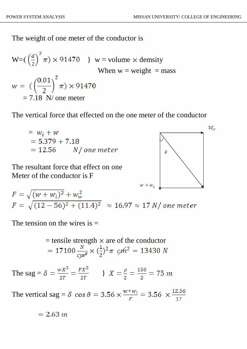
The weight of one meter of the conductor is
W= } w = volume demsity When w = weight = mass
= 7.18 N/ one meter
The vertical force that effected on the one meter of the conductor
=
The resultant force that effect on oneMeter of the conductor is F
The tension on the wires is =
= tensile strength are of the conductor
The sag = }
The vertical sag =

ANALS POWER SYSTEM ANALYSIS MISSAN UNIVERSITY\ COLLEGE OF ENGINEERING
Ex2) An overhead transmission line losses line at a river crossing issupported from two towers a high of 30 and tem respectively above waterlevel.The distance between the towers is 240 m. find the vertical distance ( clearance ) between the water level and the conductor in the middlepoint between the towers,The tension of the wires is 17800 N. and the weight of one meter of theconductor is 742 N.S01)
} T = 17800 N W = 742 N/ one meter

ANALS POWER SYSTEM ANALYSIS MISSAN UNIVERSITY\ COLLEGE OF ENGINEERING
The vertical distance between point 0 and water level30-6.75 = 25 m
} = 180+120 = 300 M
The clearance between midpoint between the towers and water level is18.75+ 23.25 = m
Ex3) An overhead transmission line at a river crossing is supported fromtwo towers. The height of one towers is 52.5 m above water levelcalculate the high of the other towers in order to make the vertical distancebetween the conductor and water level 82.5 m in a point has a horizontaldistance of 60m far from the other towers that its height more than 52.5 m.the tension in the wires is 22250 N and the weight of one meter of theconductor is 14.24 N. The distance between the towers is 300 m.
82.5m
D
60 m
L

ANALS POWER SYSTEM ANALYSIS MISSAN UNIVERSITY\ COLLEGE OF ENGINEERING
Because the tension in the wires in all point is constant so that we assumethe height 82.5 m as a tower. Therefore the new distance will bebetween the towers ( 82.5 and 52.5 )
} T= 22250 N = 240 m W= 14.24 N/ 1m
= 30 m
The shape of the towers is correct and the two towers are in the sameSide ( left or right) due to the original point 0 where point 0 is out of thetowers
The height from original point and water level g w isgw= 52.5-1.8= 50.7 m
The height of the other tower is 45+ 50.7 = 95.7 m.

ANALS POWER SYSTEM ANALYSIS MISSAN UNIVERSITY\ COLLEGE OF ENGINEERING
Ex 3) An overhead transmission line flow through a mount region has agradient of and the line is supported from two twoers each of its has aheight of 30 m and the distance between the towers is 300m the conductoris cover by ice lager of thickness of 1 cm and has a wind pressure of 380N/ .The tension in the wires is 2500 N/cThe weight of one meter of the conductor is 9 N.Also the cross- section area of the conductor is 4 cm find the height fromthe original point and ground
Note :. The height in this example means the clearance or the verticaldistance.So1)
F = 24,61 N/ 1 m
F

ANALS POWER SYSTEM ANALYSIS MISSAN UNIVERSITY\ COLLEGE OF ENGINEERING
(
We see that is positive then one tower is on the left of point 0 and theother towers is in the right ( i-e the two towers are surrounded ) point o,that mean point o location between the two towers.
30m
F
h
A
N
B
O
H
DX
C
30m
L
ANALS POWER SYSTEM ANALYSIS MISSAN UNIVERSITY\ COLLEGE OF ENGINEERING
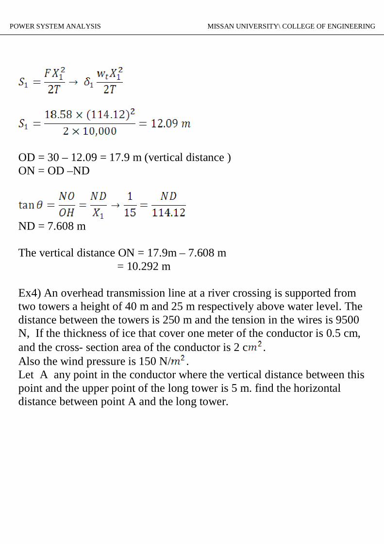
OD = 30 – 12.09 = 17.9 m (vertical distance )ON = OD –ND
ND = 7.608 m
The vertical distance ON = 17.9m – 7.608 m = 10.292 m
Ex4) An overhead transmission line at a river crossing is supported fromtwo towers a height of 40 m and 25 m respectively above water level. Thedistance between the towers is 250 m and the tension in the wires is 9500N, If the thickness of ice that cover one meter of the conductor is 0.5 cm,and the cross- section area of the conductor is 2 c .Also the wind pressure is 150 N/ .Let A any point in the conductor where the vertical distance between thispoint and the upper point of the long tower is 5 m. find the horizontaldistance between point A and the long tower.

ANALS POWER SYSTEM ANALYSIS MISSAN UNIVERSITY\ COLLEGE OF ENGINEERING
Sol) }
= 3.09 N/1 m
Because is positive value
point 0 location between the two towers.

ANALS POWER SYSTEM ANALYSIS MISSAN UNIVERSITY\ COLLEGE OF ENGINEERING
Where
O40m 35
mX
A 5m
25m
L

ANALS POWER SYSTEM ANALYSIS MISSAN UNIVERSITY\ COLLEGE OF ENGINEERING
OR in other wayTake the towers 35, 25 m respectively
Also by other towers 40, 35 m respectively

ANALS POWER SYSTEM ANALYSIS MISSAN UNIVERSITY\ COLLEGE OF ENGINEERING