mechanical engineering, 9780080965772, 2010, taylor...
TRANSCRIPT

2
Turbochargers enable an increased power output to be obtained from an internal combustion engine of a given size. Their function is to extract energy from the hot exhaust gases that would otherwise be wasted, and use it to force a greater amount of gas for combustion into the engine cylinders. Their design and the measurement of their eff ect involves the application of thermodynamics which might be described as the study of energy transfer and management.
Photo courtesy of iStockphoto, Brian Sullivan, Image # 4840390
Mechanical Engineering, 9780080965772, 2010, Taylor and Francis.

Principles and Applications of Thermodynamics
We take it for granted that electricity will be available on demand and that our cars will start at the turn of the ignition key. The greater part of our electricity is generated from fossil and nuclear fuel and it is fossil fuel that
powers our cars. The energy stored in the fuels is liberated in the form of heat, some of which is transformed into mechanical and electrical energy. Unfortunately, a great deal of the energy stored in the fuels is wasted and engineers are continually searching for ways to make the transformation processes more effi cient.
Applied thermodynamics may be described as a study of the properties of matter and the relationship between heat energy and work. It might equally be described as the study of energy management and the effi cient use of natural resources. The aim of this unit is to provide you with a basic knowledge of thermodynamics. You will investigate the combustion of fuels and the properties of air and steam. These are the working substances most widely used in heat and work transfer processes. You will also be introduced to the concept of closed and open thermodynamic systems and examine practical examples of each type.
3
Mechanical Engineering, 9780080965772, 2010, Taylor and Francis.

Principles and Applications of Thermodynamics4
Expansion and Compression of Gases
Air, steam and other working substances used in thermodynamic systems pass through a cycle of processes as heat energy is changed into work and vice versa. Expansion and compression processes often form an essential part of the cycle and we will now consider the laws, principles and properties associated with them.
Property measurement
One of the basic properties of a working substance is its temperature. Temperature is a measure of the hotness of a substance, which is directly proportional to the kinetic energy of its individual molecules. Thermodynamic temperature is measured on the kelvin scale and is also known as absolute temperature . It has for its zero, the absolute zero of temperature at which all molecular movement ceases and the molecules of a substance have zero kinetic energy.
The SI unit of temperature is the kelvin, whose symbol is ‘ K ’ . It is defi ned as the temperature interval between absolute zero and the triple point of water divided by 273.16. The triple point of water occurs at a very low pressure, where the boiling point has been depressed to meet the freezing point. In this condition, ice, water and steam are able to exist together in the same container, which is how the name arises. The kelvin is exactly the same temperature interval as the degree Celsius ( ° C). The difference between the two scales lies in the points chosen for their defi nition. The degree Celsius is defi ned as the temperature interval between the freezing and boiling points of water at standard atmospheric pressure of 101 325 Pa divided by 100. The freezing point of water at this standard pressure is slightly below the triple point, being exactly 273 K ( Table 1 ).
Table 1 Temperature scales
Temperature Kelvin scale Celsius scale
Absolute zero 0 K � 273°C
Freezing point of water at standard atmospheric pressure
273 K 0°C
Boiling point of water at standard atmospheric pressure
373 K 100°C
KEY POINT At the absolute zero of temperature all molecular movement ceases and the molecules of a substance have zero kinetic energy.
The SI unit of pressure is the Pascal (Pa). A pressure of 1 Pa is exerted when a force 1 N is evenly applied at right angles to a surface area of 1 m 2 . Another unit, which is widely used, is the ‘ bar ’ . This is almost equal to standard atmospheric pressure.
1 bar 100 000 Pa 1 10 Pa 100 kPa5� �or or
Pressure measuring devices such as mechanical gauges and the manometers measure the difference between the pressure inside a container and the outside atmospheric pressure. This is known as
KEY POINT To change the units of pressure from bars to pascals, multiply by 10 5 .
Mechanical Engineering, 9780080965772, 2010, Taylor and Francis.

Principles and Applications of Thermodynamics 5
gauge pressure . In gas calculations however it is often the total or absolute pressure , which must be used. This is obtained by adding atmospheric pressure to the recorded gauge pressure.
i.e. Absolute pressure Gauge pressure Atmospheric pressure� �
Reference has been made above to standard atmospheric pressure . A substance is said to be at standard temperature and pressure (s.t.p.) when its temperature is 0 ° C or 273 K, and its pressure is 101 325 Pa. This defi nition has international acceptance.
Sometimes a substance is said to be at normal temperature and pressure . A substance is at normal temperature and pressure (n.t.p.) when its temperature is 15 ° C or 288 K, and its pressure is again 101 325 Pa . This defi nition is used in the United Kingdom and other countries with a temperate climate.
Sometimes the density of a working substance is required for thermodynamic calculations. You will recall that density, ρ , is the mass per unit volume of a substance whose units are kg m � 3 . Sometimes however, and particularly in steam calculations, it is more convenient to use specifi c volume . This is the volume per unit mass of a substance whose units are m 3 kg � 1 . Specifi c volume, v s , is thus the reciprocal of density.
i.e. Specific volume Volume occupied by 1kg of a substance�
For a substance of mass m kg and volume V m 3 , its specifi c volume will be given by:
Specific volumeVolume
Mass
(
or, (
�
�
vVm
v1
s3 1
s3 1
m kg
m kg
�
�
� )
)ρ
In applied thermodynamics we often assume that we are dealing with an ideal gas. An ideal gas would have no viscosity, it would never condense to a liquid and would obey the gas laws (Boyle’s law and Charles ’ law) at all temperatures and pressures. Real working substances such as air and gaseous fuels behave very much like ideal gases at normal working temperatures and pressures, but we have to be very careful with steam and the fl uids used in refrigerators which need special consideration.
The gas laws
The gas laws which we need to consider are Boyle’s law, Charles ’ law and Avogadro’s law, which is also called Avogadro’s hypothesis.
Boyle’s law : This states that the volume of a fi xed mass of gas is inversely proportional to its absolute pressure provided that its temperature is constant . When plotted on a graph of absolute pressure against volume, the process appears as shown in Figure 1 .
KEY POINT Standard temperature and pressure conditions (s.t.p) are 0 ° C and 101.325 Pa.
Normal temperature and pressure conditions (n.t.p.) are 15 ° C and 101.325 Pa.
KEY POINT Like absolute temperature and absolute pressure, specifi c volume is a property of the working substance in a thermodynamic system.
Mechanical Engineering, 9780080965772, 2010, Taylor and Francis.

Principles and Applications of Thermodynamics6
Expansion and compression processes which take place at constant temperature, according to Boyle’s law, are known as isothermal processes . For any two points on the curve whose co-ordinates are p 1 V 1 and p 2 V 2 , it is found that:
p V p V
pV1 1 2 2
Constant
�
�or (1)
Charles ’ law : This states that the volume of a fi xed mass of gas is proportional to its absolute temperature provided that its pressure is constant . When plotted on a graph of absolute temperature against volume, the process appears as shown in Figure 2 .
p1(1)
Abs
olut
e pr
essu
re (P
a)
(2)p2
V1 V2
Volume (m3)
Figure 1 Expansion according to Boyle’s law – isothermal process
T2
(2)
Abs
olut
e te
mpe
ratu
re (
K)
T1
(1)
V1 V2
Volume (m3)
Figure 2 Expansion according to Charles ’ law – isobaric process
KEY POINT An expansion or compression process that takes place at a constant temperature according to Boyle’s is said to be an isothermal process.
Expansion and compression processes that take place according to Charles ’ law are referred to as constant pressure or isobaric processes . For any two points on the curve whose co-ordinates are T 1 V 1 and T 2 V 2 , it is found that:
V
T
V
T
VT
1
1
2
2
�
�or Constant
(2)
You will note from Figure 2 , that in theory, the volume of the gas should decrease uniformly until at absolute zero, which is the origin of the graph, its volume would also be zero. This is how an ideal gas would
Mechanical Engineering, 9780080965772, 2010, Taylor and Francis.

Principles and Applications of Thermodynamics 7
behave. Real gases obey the gas laws fairly closely at the temperatures and pressures normally encountered in power and process plant but at very low temperatures they liquefy, and may also solidify, before reaching absolute zero.
The general gas equation : This equation may be applied to any fi xed mass of gas which undergoes a thermodynamic process taking it from initial conditions p 1 , V 1 and T 1 to fi nal conditions p 2 , V 2 and T 2 . Suppose the gas expands fi rst according to Boyle’s law to some intermediate volume V . Let it then expand further according to Charles ’ law to its fi nal volume V 2 .
Figure 3 shows the processes plotted on a graph of absolute pressure against volume.
p1(1)
Abs
olut
e pr
essu
re (P
a)
(2)p2
V1 V V2
Volume (m3)
Figure 3 Expansion according to Boyle’s and Charles ’ laws
KEY POINT An ideal gas would obey the gas laws at all temperatures and pressures.
For the initial expansion according to Boyle’s law,
p V p V1 1 2� (i)
For the fi nal stage according to Charles ’ law,
VT
V
T1
2
2
�
(ii)
Now from equation (ii),
V
V T
T� 2 1
2
Substituting in (i) for V gives,
p V
p V T
T2
1 12 1
2
�
p V
T
p V
T
pVT
1 1
1
2 2
2
Constant
�
�or
(3)
This is the general gas equation that can be used to relate any two sets of conditions for a fi xed mass of gas, irrespective of the process or
Mechanical Engineering, 9780080965772, 2010, Taylor and Francis.

Principles and Applications of Thermodynamics8
processes which have caused the change. The constant in equation (3) is the product of two quantities. One of them is the mass, m kg, of the gas. The other is a constant for the particular gas known as characteristic gas constant . The characteristic gas constant, R has units of joules per kilogram per kelvin (J kg � 1 K � 1 ) and is related to the molecular weight of the gas. Equation (3) can thus be written as:
p
Tm
VR�
or pV mRT� (4)
In this form it is known as the characteristic gas equation which is particularly useful for fi nding the mass of a gas whose volume, absolute pressure and absolute temperature are known.
Avogadro’s hypotheses : This states that equal volumes of different gases at the same temperature and pressure contain the same number of molecules . It is called a hypothesis because it cannot be directly proved. It is impossible to count the very large number of molecules, even in a small volume, but there is lots of evidence to indicate that the assumption is true. Suppose we have three vessels of equal volume containing three different gases at the same temperature and pressure, as shown in Figure 4 .
Gas 1
Molecular mass = M1
Characteristic gasconstant = R1
Gas 2
Molecular mass = M2
Characteristic gasconstant = R2
Gas 3
Molecular mass = M3
Characteristic gasconstant = R3
Figure 4 Equal volumes of different gases at the same temperature and pressure
KEY POINT The general gas equation can be used to relate any two sets of conditions for a fi xed mass of gas, irrespective of the process or processes which have taken place.
Avogadro’s hypothesis states that each vessel contains the same number of molecules. Let this number be N . The mass of gas in each vessel will be different, and is given by:
Mass of gas in vessel Number of molecules Molecular mass� �
m NM� (i)
Applying the characteristic gas equation to the fi rst vessel gives:
pV m R TpV
Tm R
�
�
1 1
1 1or
Substituting for m 1 from (i)
pVT
NM R� 1 1
(ii)
Mechanical Engineering, 9780080965772, 2010, Taylor and Francis.

Principles and Applications of Thermodynamics 9
Similarly for the gases in the other two vessels.
pVT
NM R� 2 2
(ii)
and
pVT
NM R� 3 3
(iii)
Equating (i), (ii) and (iii) gives:
N M R NM R NM R1 1 2 2 3 3� �
M R M R M R1 1 2 2 3 3 Constant� � � (iv)
The actual mass of a molecule is very small and so in place of it, engineers and chemists use the kilogram-molecule or kmol. This is the mass of the substance, measured in kilograms, which is numerically equal to its molecular weight. The molecular weight is the weight or mass of a molecule of the gas relative to the weight or mass of a single hydrogen atom. Typical values for some common gases are shown in Table 2 . The same symbol M is used and so for oxygen, M � 32 kg and for nitrogen, M � 28 kg, as given in Table 2 .
Table 2 Molecular weights
Gas Chemical symbol for molecule
Molecular weight (M)
Hydrogen H 2 2
Nitrogen N 2 28
Oxygen O 2 32
Carbon monoxide CO 28
Carbon dioxide CO 2 44
The product MR is found to have a value of 8314 J kmol � 1 and is called the universal gas constant . It can be used to calculate the value of the characteristic gas constant, R , for a particular gas of known molecular weight.
MR � 8314
R
M�
8314
(5)
e.g., the molecular weight of oxygen is 32 and so the value of its characteristic gas constant will be:
R � � � �8314
32260 J kg K1 1
Air is of course a mixture of oxygen and nitrogen and so its characteristic gas constant cannot be found in this way. It can however be shown that its value is 287 J kg � 1 K � 1 .
KEY POINT A kilogram-molecule or kmol of a substance is the mass in kilograms which is numerically equal to its molecular weight.
Mechanical Engineering, 9780080965772, 2010, Taylor and Francis.

Principles and Applications of Thermodynamics10
Example 1 A compressor takes in carbon dioxide at a pressure of 1 bar and temperature 20 ° C and delivers it through an aftercooler to a receiving vessel at a pressure of 6 bar. The initial volume in the compressor cylinder is 0.2 m 2 and the piston compresses it into a volume of 0.05 m 3 . There is no loss of pressure in the aftercooler and the molecular weight of CO 2 is 44. Determine (a) the mass of gas delivered per stroke of the piston, (b) the temperature on entering the aftercooler, (c) the volume of gas entering the receiver per stroke of the piston if it is cooled to its initial temperature in the aftercooler ( Figure 5 ).
p3 � p2(2)
Pre
ssur
e (P
a)
(1)p1
V3 V2 V1
Volume (m3)
(3)
Figure 5 Pressure–volume diagram
(a) Finding characteristic gas constant for CO 2 .
R
M� �
8314 831444
R � 189 Jkg K1 1� �
Finding mass of gas.
p V m RT1 1 1
�
m
p VRT
� 1 1
1
where p 1 � 1 � 10 5 Pa and T 1 � (20 � 273) � 293 K
m ��
�
1 10 0 2189 293
5� .
m � 0.361 kg
(b) Finding temperature T 2 at the end of the compression stroke.
p VT
p VT
Tp V T
p V
1 1
1
2 2
2
22 2 1
1 1
5
5
6 10 0 05 293
1 10 0 2
�
� �� � �
� �
.
.
T2 440 K o� rr 167 C�
(c) Finding volume V 3 delivered from aftercooler to receiver per piston stroke.
p VT
p VT
1 1
1
3 3
3
�
Mechanical Engineering, 9780080965772, 2010, Taylor and Francis.

Principles and Applications of Thermodynamics 11
But T 3 � T 1 . These can be eliminated leaving,
p V p V
Vpp
1 1 3 3
31 1
3
V
�
�
where p 3 � p 2 � 6 � 10 5 Pa.
V3
5
5
1 10 0 2
6 10�
� �
�
.
V330.0333 m�
There was really no need to change the pressures to pascals in parts (b) and (c). Because the pressures are in the ratios p 2 /p 1 and p 1 /p 3 , they could have been left in ‘ bars ’ . You might do this in future calculations but be sure to use the same units for the top and bottom lines of a ratio.
You might note that the cooling process from (2) to (3) took place at constant pressure, i.e., according to Charles ’ law. You might also note that because the initial and fi nal temperatures were the same, the fi nal condition of the CO 2 was the same as
if isothermal compression had taken place from (1) to (3), i.e., according to Boyle’s law.
Polytropic expansion
A fi xed mass of gas can expand from an initial pressure p 1 and volume V 1 in an infi nite number of ways. This is what we mean by the word polytropic . The graph in Figure 6 shows some of possible expansion processes.
All curves follow a law of the form
pV n = c
0 < n
p1 n = 0
Pre
ssur
e 0 < n < 1
n = 1
1 < n < g
n = g Adiabatic orisentropic expansion
g < n
V1 V2
Volume
Isobaric expansion– Charles’ law
Isothermal expansion– Boyle’s law
Figure 6 Polytropic expansion
Mechanical Engineering, 9780080965772, 2010, Taylor and Francis.

Principles and Applications of Thermodynamics12
The particular expansion curve followed by a gas depends on the amount and direction of the heat transfer that takes place during the expansion process. All of the curves have an equation of the general form:
pV n � Constant
or p V p Vn n1 1 2 2�
(6)
For most practical expansion and compression processes the value of the index n ranges from low negative values to positive values of around 1.5. The values of n indicated in Figure 6 correspond to the following conditions.
n � 0 Very large amounts of heat energy are being received during the expansion process. Not only does the volume increase but the temperature and pressure also increase during the process.
n � 0 Less heat energy being received. The temperature rises but the pressure stays constant. This is isobaric expansion which takes place according to Charles ’ law. Equation (6) becomes:
p V p V1 10
2 20�
You will remember from your mathematics that any number to the power zero is 1. The equation thus reduces to p 1 � p 2 , i.e., constant pressure.
0 � n � 1 Less heat energy is being received in this range. The temperature continues to rise but the pressure falls during expansion.
n � 1 Still less heat energy being received. The temperature stays constant and the pressure falls. This is isothermal expansion which takes place according to Boyle’s law. Equation (6) becomes:
p V p V1 1 2 2�
As would be expected, this is exactly the same as equation (1)
1 � n � γ Only small amounts of heat energy being received. The temperature and pressure both fall during expansion.
n � γ This is known as adiabatic or isentropic expansion where no heat transfer takes place during the expansion process. Like isobaric and isothermal expansion, it is a special case which we will discuss later in more detail. The temperature and pressure both fall and the value of the index γ for air is around 1.4.
γ � n In this range, heat energy is lost by the gas during expansion. The temperature and pressure both fall by increasing amounts.
KEY POINT The value of the index ‘ n ’ in a polytrophic process depends on the magnitude and direction of the heat transfer that takes place.
Mechanical Engineering, 9780080965772, 2010, Taylor and Francis.
Principles and Applications of Thermodynamics 13
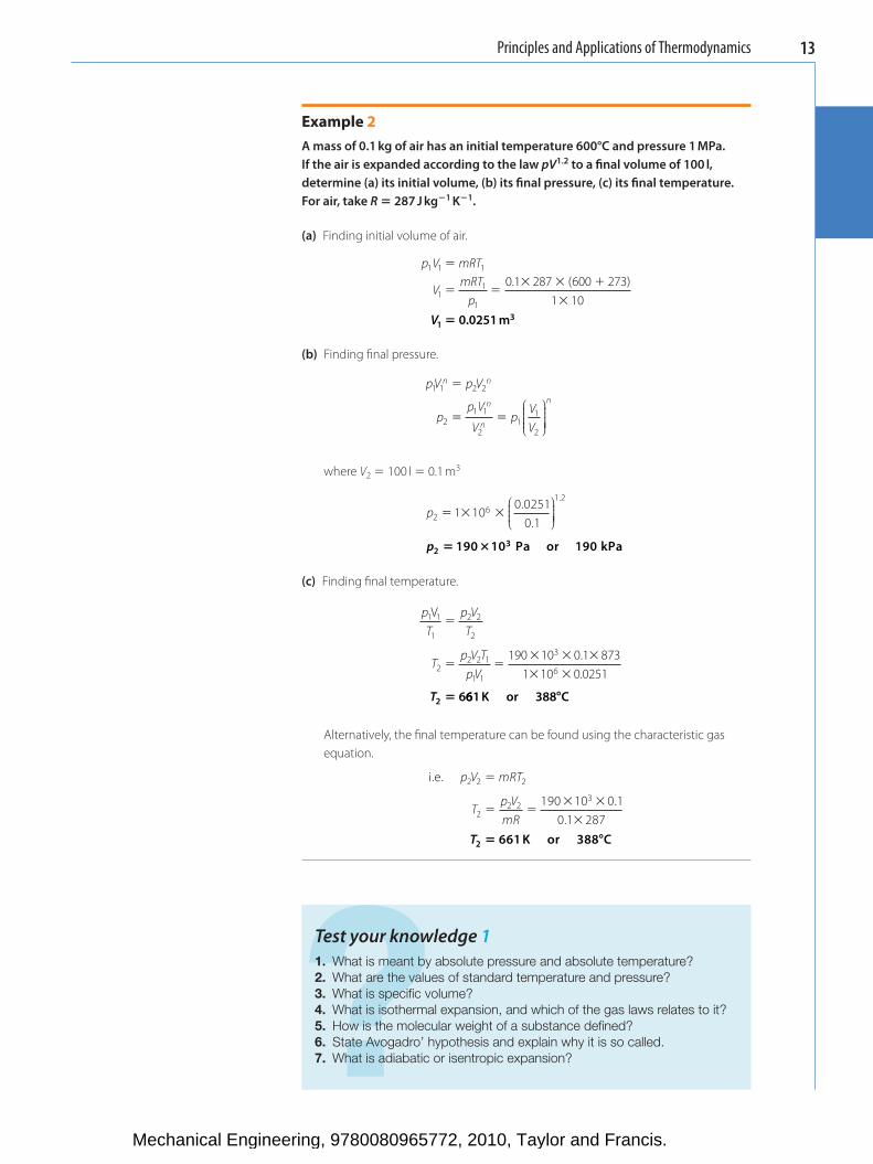
Example 2 A mass of 0.1 kg of air has an initial temperature 600 ° C and pressure 1 MPa. If the air is expanded according to the law pV 1.2 to a fi nal volume of 100 l, determine (a) its initial volume, (b) its fi nal pressure, (c) its fi nal temperature. For air, take R � 287 J kg � 1 K � 1 .
(a) Finding initial volume of air.
p V mRT
VmRT
p
1 1 1
11
1
0 1 287 600 2731 10
�
� �� � �
�
. ( )
V130.0251 m�
(b) Finding fi nal pressure.
p V p V
p V
Vp
VV
n n
n
n
n1 1 2 2
21 1
21
1
2
�
� �p⎛
⎝⎜⎜⎜⎜
⎞
⎠⎟⎟⎟⎟⎟
where V 2 � 100 l � 0.1 m 3
p26
1 2
1 100 0251
0 1� � �
..
.⎛⎝⎜⎜⎜
⎞⎠⎟⎟⎟⎟
p23190 10 Pa or 190 kPa� �
(c) Finding fi nal temperature.
pT
p VT
Tp V T
p V
1 1
1
2 2
2
22 2 1
1 1
3
6
190 10 0 1 8731 10 0 0251
V�
� �� � �
� �
.
.
T2 6� 661 K or 388 C �
Alternatively, the fi nal temperature can be found using the characteristic gas equation.
i.e. p V mRT
Tp VmR
2 2 2
22 2
3190 10 0 10 1 287
�
� �� �
�
..
T2 661 K or 388 C� �
? Test your knowledge 1 1. What is meant by absolute pressure and absolute temperature? 2. What are the values of standard temperature and pressure? 3. What is specifi c volume? 4. What is isothermal expansion, and which of the gas laws relates to it? 5. How is the molecular weight of a substance defi ned? 6. State Avogadro ’ hypothesis and explain why it is so called. 7. What is adiabatic or isentropic expansion?
Mechanical Engineering, 9780080965772, 2010, Taylor and Francis.

Principles and Applications of Thermodynamics14
Activity 1 A petrol engine has a cylinder diameter of 90 mm and a stroke of 100 mm. The compression ratio is 8:1. At the start of the compression stroke, the cylinder is full of a petrol/air mixture at a pressure of 1 bar and temperature 25 ° C. Compression takes place according to the law pV 1.3 � c and the molecular weight of the mixture can be taken to be 29. Determine (a) the mass of gas in the cylinder, (b) the pressure and temperature at the end of the compression stroke.
Thermodynamic Systems
A thermodynamic system is defi ned as a quantity of matter surrounded by a real or imaginary boundary across which energy may pass in the form of heat and work. Its surroundings are considered to be all matter outside the boundary. The matter inside the system is known as the working substance, two of the most common being air and steam.
Properties of a thermodynamic system
There are six commonly used properties which describe the state of the working substance in a thermodynamic system. They are:
(1) Absolute pressure (Pascals) Intensive properties (2) Absolute temperature (Kelvin)
(3) Specifi c volume (m 3 ) (4) Internal energy (J kg � 1 ) Extensive properties (5) Enthalpy (J kg � 1 ) (6) Entropy (J kg � 1 K � 1 )
Absolute pressure and absolute temperature are called intensive properties because they are independent of the mass of the working substance inside a thermodynamic system. The remaining four properties are all dependent on mass, as can be seen from their units. They are called extensive properties . We have already described the fi rst three properties and we will shortly be defi ning internal energy and enthalpy. The last of the properties, entropy, will be left for study at a higher level. It is used in advanced steam plant calculations which are beyond the range of this unit.
Two property rule
This states that the condition of the working substance in a thermodynamic system can be fully defi ned by any two of its properties provided that they are fully independent of each other . In other words, if you know the value of any two properties, such as pressure and volume or temperature, enthalpy, etc. you can use these to defi ne the condition of a working substance and to calculate other properties.
KEY POINT Temperature and pressure are independent of the mass of the working substance present in a thermodynamic system.
�
�
Mechanical Engineering, 9780080965772, 2010, Taylor and Francis.

Principles and Applications of Thermodynamics 15
Care must be taken when the working substance is a vapour in contact with its liquid phase, such as wet steam in a boiler. Here the temperature and pressure are not independent. The temperature at which the water is boiling to produce the steam depends on the pressure in the boiler. In such cases another property such as internal energy or enthalpy is required to fully defi ne the condition of the steam.
Zeroth law of thermodynamics
There are three laws of thermodynamics that we need to consider, the zeroth, the fi rst and the second. Presumably the zeroth was an afterthought, and should really have been the fi rst. It defi nes thermal equilibrium between bodies and states that if two bodies are each in thermal equilibrium with a third body, they must also be in thermal equilibrium with each other .
A body is in thermal equilibrium when its temperature is constant and there is no change of state taking place, i.e., the body is not melting or evaporating. When bodies in close contact are in thermal equilibrium, there is no heat transfer between them and they are at the same temperature. A good example is a thermometer displaying a steady temperature reading. In this condition the mercury, the glass that contains it and the substance whose temperature is being measured must all be thermal equilibrium with each other.
First law of thermodynamics
This is a statement of the principle of conservation of energy applied to thermodynamic systems. It was put forward by the German physicist Rudolf Clausius (1822–1888) and states that the total energy of a thermodynamic system and its surroundings is constant although changes may take place from one energy form to another .
More specifi cally, for closed thermodynamic systems such as internal combustion engines and steam generating plant, it can be stated that when a closed thermodynamic system is taken through a cycle of processes, the net heat transfer is equal to the net work done. As in other walks of life, this means that you cannot get more out of a system than you put in to it.
Heat transfer
The molecules of a solid body are thought be in a state of vibration whilst those in liquids and gases move in a random fashion. Whatever the state or phase of a substance, its molecules have kinetic energy. As we have already stated, temperature is an indirect measure of molecular kinetic energy, which is experienced as hotness or coldness to the touch. The greater the mass of a substance, the greater will be the number of molecules and the greater will be the total amount of kinetic energy that it contains. This is in fact its heat energy content but it is more usually called internal energy . Like other energy forms, it is measured in joules and is one of the extensive properties which can be used to defi ne the state of a thermodynamic system.
KEY POINT The temperature of the steam generated in a boiler depends on the boiler pressure.
KEY POINT Bodies in close contact are in thermal equilibrium, when they are at the same temperature and there is no heat transfer between them.
KEY POINT The internal energy of a substance is the sum of the kinetic energies of its molecules.
Mechanical Engineering, 9780080965772, 2010, Taylor and Francis.

Principles and Applications of Thermodynamics16
Because it is almost impossible to count the number of molecules in a substance or to measure their kinetic energies, it is diffi cult to calculate the total internal energy of any given mass. This does not present a problem however because it is the change of internal energy, or the heat transfer which accompanies temperature change, which is of more importance. This can be calculated and depends upon:
● the mass of the substance ● the change of temperature which occurs ● the specifi c heat capacity of the substance.
Specifi c heat capacity
The specifi c heat capacity of a substance is defi ned as the amount of heat energy required to raise the temperature of a mass of 1 kg through a temperature rise of 1 K (1 ° C) .
It is given the symbol c , and its units are J kg � 1 K � 1 . The value of specifi c heat capacity for different substances is found by experiment. Its value varies a little with the temperature at which heat transfer takes place and those listed in Table 3 are accepted average values for the temperature ranges normally encountered in process plant.
Table 3 Specifi c heat capacities
Substance Specifi c heat capacity (J kg � 1 K � 1 )
Metals
Aluminium 920
Carbon steels 460
Cast iron 540
Copper and brass 390
Lead 130
Mercury 140
Non-metals
Water 4200
Ice 700
Alcohol 230
The specifi c heat capacity of a gas is dependent on the conditions under which heat transfer takes place. Two standard conditions are used. They are heat transfer at constant volume and heat transfer at constant pressure. As a result, a gas has two specifi c heat capacities c v at constant volume and c p at constant pressure. The values of c v and c p for some common gases are listed in Table 4 .
It will be noted that in Table 4 , the values of specifi c heat capacity at constant pressure are 30–40% higher than those at constant volume. This is because heat transfer at constant pressure is accompanied by expansion of the gas. When a gas expands it does external work in pushing back its system boundary and this is why additional heat energy is required.
KEY POINT A gas has two specifi c heat capacities, the specifi c heat capacity at constant pressure, c p , and the specifi c heat capacity at constant volume, c v .
Mechanical Engineering, 9780080965772, 2010, Taylor and Francis.

Principles and Applications of Thermodynamics 17
Heat fl ow
When a substance of mass m kg and specifi c heat capacity c J kg � 1 K � 1 undergoes a temperature change from T 1 ° C to T 2 ° C, the heat transfer Q J which takes place is given by the formula:
Q m T Tc� �( )2 1 (7)
If the temperature rises, heat energy is received and Q is positive. If the temperature falls, heat energy is lost and Q is negative. In the case of solid bodies the product mc is sometimes referred to as its thermal capacity whose units are joules per kelvin (J K � 1 ).
When a liquid is heated in a metal container, some of the heat energy supplied goes to raising the temperature of the metal. Sometimes it is convenient to consider the mass of water to which the metal is equivalent. This is called the water equivalent , of the container which is defi ned as the mass of water which would experience the same temperature rise when receiving the same amount of heat energy . The water equivalent m wc kg of a container whose mass is m c kg and specifi c heat capacity c c J kg � 1 K � 1 is given by the formula:
m
c
cmwc
c
wc�
(8)
where c w is the specifi c heat capacity of water. The total heat transfer to or from the container and contents is then given by:
Q m m c T T� � �( ( )w wc w 2 1) (9)
If the heat transfer given by equation (7) takes place in a time t s, the power of the heating or cooling process is given by:
Power
Heat
Time taken�
transfer
Power (W)
Power( ) (W)2 1
�
��
Qtm T T
tc
(10)
Table 4 Specifi c heat capacities of gases
Gas Specifi c heat capacity (J kg � 1 K � 1 )
At constant volume, c v
At constant pressure, c p
Air 718 1005
Nitrogen 740 1004
Oxygen 660 920
Carbon monoxide 740 1040
Carbon dioxide 630 850
KEY POINT The water equivalent of a vessel is defi ned as the mass of water that would experience the same temperature rise when receiving the same amount of heat energy.
Mechanical Engineering, 9780080965772, 2010, Taylor and Francis.

Principles and Applications of Thermodynamics18
Example 3 A cylindrical boiler drum 5 m long and 2 m diameter has a mass of 4 tonnes and is lagged to prevent heat loss. The drum is made from steel of specifi c heat capacity 460 J kg � 1 K � 1 and is two-thirds full of water at a temperature of 15 ° C. After supplying heat at a steady rate for 30 min the water temperature is raised to100 ° C. The density of water is 1000 kg m � 3 and its specifi c heat capacity is 4200 J kg � 1 K � 1 . Determine (a) the water equivalent of the boiler drum, (b) the heat energy supplied, (c) the power rating of the process.
(a) Finding water equivalent of boiler drum.
mcc
mwcc
wc� �
� �460 4 104200
3
mwc 438 kg�
(b) Finding volume of water in boiler drum.
Vd l
w � �� � �
�
23 4
2 2 53 4
2 2� �
Vw310.5 m�
Finding mass of water in drum.
m Vw � � �� 1000 10 5.
mw 10 500 kg�
(c) Finding heat energy received.
Q m m c T T
Q
� � �
� � � � �
( ) ( )
( ) ( )
w wc w 2 1
10 500 438 4200 100 15
Q � �3.90 109 JJ or 3.90 GJ
(d) Finding power rating of process.
Power � ��
�
Qt
3 90 1030 60
9.
Power 2.17 10 W or 2.17 MW6� �
Heat transfer in mixtures
Suppose a hot body A of mass m A , specifi c heat capacity c A and temperature T A is plunged into a cool liquid B of mass m B , specifi c heat capacity c B and temperature T B . The substance A will loose heat energy and, assuming that the container is perfectly lagged, the liquid B and its container C will receive the same amount. Let the mass of the container be m c and its specifi c heat capacity be c c . Eventually the mixture will achieve thermal equilibrium where heat transfer ceases and the two substances are at a common fi nal temperature T . In this condition,
Heat energy lost by A Heat energy received by B and it co� s nntainer
A A B B B c c Bm c T T m c T T m c T TA ( ) ( ) ( )� � � � �
m c T T m c m c T TA A A B B c c B( ) ( )(� � � � )
(11)
Mechanical Engineering, 9780080965772, 2010, Taylor and Francis.
Principles and Applications of Thermodynamics 19
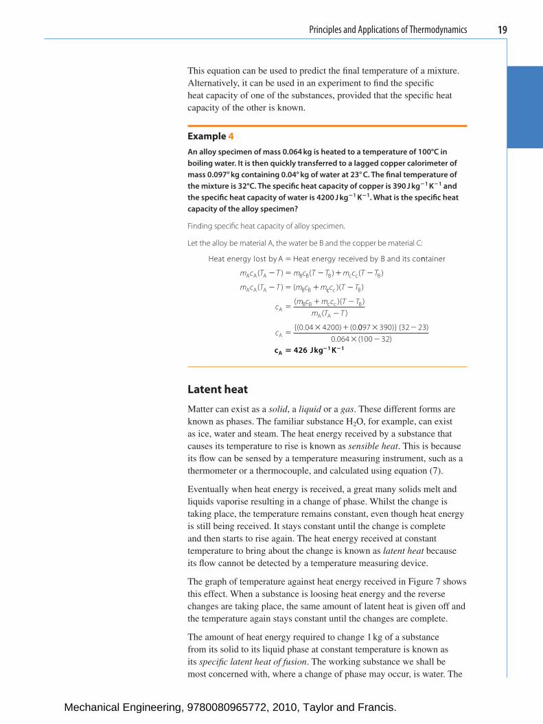
This equation can be used to predict the fi nal temperature of a mixture. Alternatively, it can be used in an experiment to fi nd the specifi c heat capacity of one of the substances, provided that the specifi c heat capacity of the other is known.
Example 4 An alloy specimen of mass 0.064 kg is heated to a temperature of 100 ° C in boiling water. It is then quickly transferred to a lagged copper calorimeter of mass 0.097 ° kg containing 0.04 ° kg of water at 23 ° C. The fi nal temperature of the mixture is 32 ° C. The specifi c heat capacity of copper is 390 J kg � 1 K � 1 and the specifi c heat capacity of water is 4200 J kg � 1 K � 1 . What is the specifi c heat capacity of the alloy specimen?
Finding specifi c heat capacity of alloy specimen.
Let the alloy be material A, the water be B and the copper be material C:
Heat energy lost by A Heat energy received by B and its co � nntainer
A A A B B B c c B
A A A B B
m c T T m c T T m c T T
m c T T m c m
( ) ( ) ( )
( ) (
� � � � �
� � � cc c B
AB B c c B
A A
A
c T T
cm c m c T T
m T T
c
)( )
( )( )( )
{( ) (
�
�� �
�
�� �0 04 4200 0. .0097 390 32 23
0 064 100 32� �
� �
)} ( )( ).
c 426 Jkg KA1 1� � �
Latent heat
Matter can exist as a solid , a liquid or a gas . These different forms are known as phases. The familiar substance H 2 O, for example, can exist as ice, water and steam. The heat energy received by a substance that causes its temperature to rise is known as sensible heat . This is because its fl ow can be sensed by a temperature measuring instrument, such as a thermometer or a thermocouple, and calculated using equation (7).
Eventually when heat energy is received, a great many solids melt and liquids vaporise resulting in a change of phase. Whilst the change is taking place, the temperature remains constant, even though heat energy is still being received. It stays constant until the change is complete and then starts to rise again. The heat energy received at constant temperature to bring about the change is known as latent heat because its fl ow cannot be detected by a temperature measuring device.
The graph of temperature against heat energy received in Figure 7 shows this effect. When a substance is loosing heat energy and the reverse changes are taking place, the same amount of latent heat is given off and the temperature again stays constant until the changes are complete.
The amount of heat energy required to change 1 kg of a substance from its solid to its liquid phase at constant temperature is known as its specifi c latent heat of fusion . The working substance we shall be most concerned with, where a change of phase may occur, is water. The
Mechanical Engineering, 9780080965772, 2010, Taylor and Francis.

Principles and Applications of Thermodynamics20
specifi c latent heat of fusion required to melt ice at standard atmospheric pressure is 335 kJ kg � 1 . It is also known as the specifi c enthalpy of fusion and given the symbol h s . You will recall that enthalpy is one of the six properties used to describe the state of a working substance and very shortly we shall be looking at its precise defi nition.
The latent heat required to change m kg of a substance from a solid to a liquid, or given off when a liquid changes to a solid, is given by the formula:
Latent heat Mass Specific latent heat of fusion � �
Q mh� s (12)
The amount of heat energy required to change 1 kg of a substance from its liquid to its gaseous phase at constant temperature is known as its specifi c latent heat of vaporisation. The specifi c latent heat of fusion required to change water to dry steam at standard atmospheric pressure is 2257 kJ kg � 1 . It is also known as the specifi c enthalpy of vaporisation and given the symbol h fg . Do not worry about the reason for using the suffi x fg. It will be explained later.
The latent heat required to change m kg of a substance from a liquid to a vapour, or given off when a vapour changes to a liquid, is given by the formula:
Latent heat Mass Specific latent heat of vaporisation � �
Q mh� fg
(13)
Example 5 Calculate the heat energy required to change 20 kg of ice at � 4 ° C to dry steam at 100 ° C and atmospheric pressure. The specifi c heat capacity of ice is 2.1 kJ kg � 1 K � 1 and the specifi c latent heat of fusion is 335 kJ kg � 1 . The specifi c heat capacity of water is 4.2 kJ kg � 1 K � 1 and the specifi c latent heat of vaporisation is 2257 kJ kg � 1 . If the time taken is 25 min, calculate also the power of the heating process.
Solidphase
Liquidphase
Gaseous phase
Boiling point
Tem
pera
ture
(°C
)
Latent heat ofvaporisation
Freezing point Temperature is constantduring changes of state
Latent heatof fusion
Heat energy (J)
Figure 7 Graph of temperature against heat energy received
KEY POINT Sensible heat transfer produces temperature change whilst latent heat transfer produces a change of phase.
Mechanical Engineering, 9780080965772, 2010, Taylor and Francis.

Principles and Applications of Thermodynamics 21
Finding Q 1 , the sensible heat energy required to raise the temperature of the ice from � 4 ° C to 0 ° C.
Q mc T T1 2 1320 2 1 10 0 4� � � � � � �ice( ) ]. [ ( )
Q 168 10 J or 168 kJ13� �
Finding Q 2 , the latent heat required to change the ice to water at 0 ° C.
Q mh2320 335 10� � � �s
Q236700 10 J or 6700 kJ� �
Finding Q 3 , the sensible heat energy required to raise the temperature of the water from 0 ° C to 100 ° C.
Q mc T T3 3 2320 4 2 10 100 0� � � � � � �w( ) ( )
.
Q338400 10 J or 8400 kJ� �
Finding Q 4 , the latent heat required to change the water into dry stream at 100 ° C.
Q mh4320 2257 10� � � �fg
Q4345140 10 J or 45140 kJ� �
Finding total heat energy required.
Q Q Q Q Q
Q
� � � �
� � � �
1 2 3 4
168 6700 8400 45140
Q � 60 408 kJ
Finding power of heating process.
Power � ��
�
Qt
60 1025 60
3408
Power 40.3 10 W or 40.3 kW3� �
? Test your knowledge 2 1. Distinguish between intensive and extensive thermodynamic properties. 2. What is the two property rule? 3. What is the fi rst law of thermodynamics? 4. How are the two specifi c heat capacities of a gas defi ned? 5. What is the difference between sensible heat and latent heat? 6. What is the water equivalent of a container?
Activity 2 Dry steam at 100 ° C enters a spray condenser at the rate of 2.1 kg min � 1 . Cooling water at a temperature of 15 ° C is sprayed into the steam and the condensate/cooling water mixture drains off at the rate of 2.55 kg min � 1 . If radiation losses are neglected, what will be the fi nal temperature of the mixture? The specifi c heat capacity of water is 4200 J kg � 1 K � 1 and its specifi c latent heat of vaporisation is 2257 kJ kg � 1 .
Mechanical Engineering, 9780080965772, 2010, Taylor and Francis.

Principles and Applications of Thermodynamics22
Work transfer
When a gas expands, it does work. The hot gases in an internal combustion engine expand and push the pistons down the cylinders giving work output from the system. On the compression stroke, the opposite happens and work is put into the system. The work output from a thermodynamic system is usually regarded as positive work and the work input is taken to be negative work. This is the opposite sign convention to that used for heat transfer. You will recall that heat input to a system is positive whilst heat output, or heat loss, is negative.
Suppose that a fi xed mass of gas expands according to the general polytropic law pV n � c , as shown in Figure 8 .
Piston area = Ap Work output = W
dxp1 (1)
Pre
ssur
e (P
a)
pVn
= c
pp2
(2)dV
V1 V2
Volume (m3)
Figure 8 Polytropic expansion
At some instant during the expansion process when the pressure is p , the piston moves through a small distance d x and the volume increases by a small amount d V. During this instant a small amount of work dW is done by the gas.
Work done Force on piston Distance moved by pistond
d
� �
� �W F x pAA xd
But A d x � d V , the small increase in volume.
d dW p V�
This is the area of the elemental strip under the curve and so the total work done during expansion from (1) to (2) is the total area under the curve. This can be found by integration between the limits V 1 and V 2 .
W p vv
v
� d1
2
∫
(i)
Now the equation of the curve is pV n � c and so,
p
c
VcV
nn� � �
Mechanical Engineering, 9780080965772, 2010, Taylor and Francis.

Principles and Applications of Thermodynamics 23
Substituting for p in (i) gives:
W cV V
WcV
n
WcV
n
cV
n
v
v
n
V
V
n n
�
�
��
�
�
�
� �
d1
2
1
21
21
11
1
1 1
∫
⎛
⎝⎜⎜⎜⎜
⎞
⎠⎟⎟⎟⎟�
�� n
W
cV cV
n
n n
��
�
� �21
11
1 (ii)
But p 1 V 1 n � c and also p 2 V 2
n � c . Substituting for these in (ii) gives:
W
p V V p V V
n
n n n n
��
�
� �2 2 2
11 1 1
1
1
W
p V p V
n�
�
�2 2 1 1
1 (iii)
Because the index n is usually greater than 1, it is convenient to reverse the terms in the numerator and denominator giving:
W
p V p V
n�
�
�1 1 2 2
1 (14)
Now from the characteristic gas equation, p 1 V 1 � mRT 1 and p 2 V 2 � mRT 2 . Substituting for these in equation (14) gives:
W
mRT mRT
n�
�
�1 2
1
W
mR T T
n�
�
�
( )
11 2
(15)
When these formulae are used, it will be found that the value of W is always positive for an expansion process and negative for a compression process.
The formulae can be used to fi nd the work transfer during any polytropic process except one. That is the isothermal process which takes place according to Boyle’s law. For isothermal expansion, n � 1 and this makes equations (14) and (15) indeterminate. We must therefore start again with the pressure vs. volume graph shown in Figure 9 .
The work done is again the area under the curve.
W p vv
v
� d1
2
∫
(i)
Mechanical Engineering, 9780080965772, 2010, Taylor and Francis.

Principles and Applications of Thermodynamics24
Now the equation of the curve is pV � c and so,
p
c
VcV� � �1
Substituting for p in (i) gives:
W cV vv
v
� �1
1
2
d∫
You may remember from your mathematics that this is the special case of integration which gives:
W c V
W c V c V
V
V�
� �
ln
ln
( )1
2
2 1ln
W c
V
V� ln 2
1
⎛
⎝⎜⎜⎜⎜
⎞
⎠⎟⎟⎟⎟
(ii)
But pV � c . Substituting for c in (ii) gives:
W pV
V
V� ln 2
1
⎛
⎝⎜⎜⎜⎜
⎞
⎠⎟⎟⎟⎟
(16)
Now from the characteristic gas equation, pV � mRT , where T is the constant temperature at which the process takes place. Substituting for pV in equation (16) gives:
W � mRT
V
Vln 2
1
⎛
⎝⎜⎜⎜⎜
⎞
⎠⎟⎟⎟⎟
(17)
p1 (1)
Pre
ssur
e (P
a)
p
p2(2)
dV
V1 V2Volume (m3)
pV = c
Figure 9 Isothermal expansion
Mechanical Engineering, 9780080965772, 2010, Taylor and Francis.

Principles and Applications of Thermodynamics 25
Example 6 Air with an initial volume of 0.1 m 3 , pressure 1 bar and temperature 15 ° C is compressed according to the law pV 1.3 � c through a 9:1 compression ratio. It is allowed to expand isothermally back to its initial volume. Determine (a) the pressure and temperature after compression, (b) the fi nal pressure, (c) the net work done.
The pressure–volume diagram ( Figure 10 ) for the processes is as follows:
p2(2)
pV = c
Pre
ssur
e (P
a)
p3(3)
pVn
= cp1
(1)
V2 V1 = V3
Volume (m3)
Figure 10 Pressure–volume diagram
(a) Finding pressure p 2 after compression.
p V p V
p pVV
pVV
p
n n
n
n
n
1 1 2 2
2 11
21
1
2
25 11 10 10
�
� �
� � �
⎛
⎝⎜⎜⎜⎜
⎞
⎠⎟⎟⎟⎟⎟
( ) .33
p262.0 10 Pa or 2.0 Mpa� �
Finding temperature T 2 after compression.
p VT
p VT
Tp Vp V
T
1 1
1
2 2
2
22 2
1 11
6
5
2 0 10 0 01 15 2731 10 0 1
�
� �� � � �
� �
. ..
( )
T22 576 K or 303 C� �
(b) Finding fi nal pressure p 3 .
p V p V
pp VV
2 2 3 3
32 2
3
62 0 10 0 010 1
�
� �� �. .
.
p33200 10 Pa or 200 Kpa� �
(c) Finding work done, W 1 � 2 during compression process.
Wp V p V
n
W
1 21 1 2 2
1 2
5 6
1
1 10 0 1 2 10 0 011 3 1
�
�
��
�
�� � � � �
�
( ) ( ). ..
W1 2 3� � � 33.3 10 J or 33.3 kJ3� �
Mechanical Engineering, 9780080965772, 2010, Taylor and Francis.

Principles and Applications of Thermodynamics26
(The negative sign denotes work input, or work done on the air.)
Finding work done, W 2–3 , during the isothermal expansion process.
W p VVV
W
2 3 2 23
2
2 362 10 0 01
�
�
�
� � � �
(10)
ln
ln
⎛
⎝⎜⎜⎜⎜
⎞
⎠⎟⎟⎟⎟⎟
.
W2 3� � 446.1 10 J or 46.1 kJ3�
(The positive answer denotes work output, or work done by the air.)
Finding net work done, W 1 – 3 .
W W W
W
1 3 1 2 2 3
1 3 33 3 46 1
� � �
�
� �
� � �. .
W1 3 12.8 kJ� � (The positive answer denotes that there is a net work output.)
? Test your knowledge 3 1. What does the area under a pressure–volume graph indicate? 2. What is the sign convention for work transfer? 3. Why does the isothermal process require a special formula for work
transfer? 4. What will the general formula for work transfer reduce to for a process
which obeys Charles ’ law?
Activity 3 (a) The cylinder of petrol engine has a bore of 90 mm, a stroke of 100 mm and
a compression ratio of 7.5:1. At the start of the compression process the temperature of the cylinder contents is 30 ° C and the pressure is 101 kPa. If compression takes place according to the law pV 1.3 � c , determine (a) the mass of gas in the cylinder, (b) the temperature at the end of compression, (c) the work done during compression. The characteristic gas constant for air is 287 J kg� 1 K � 1 .
Closed thermodynamic system energy equation
In a closed thermodynamic system, the boundary is continuous and none of the working substance may enter or leave whilst a thermodynamic process is taking place. An example of such a system is a quantity of air enclosed in the cylinder of an engine or compressor with the valves closed. The system boundary is drawn by the cylinder head, the cylinder walls and the piston crown. Although the piston moves, it is assumed that none of the air escapes past it. Energy may however pass across the system boundary in the form of heat or work.
The working fl uid in a closed system contains energy by virtue of its temperature. As we have stated, this is called internal energy , which will change in the course a thermodynamic process if the temperature
Mechanical Engineering, 9780080965772, 2010, Taylor and Francis.

Principles and Applications of Thermodynamics 27
changes. Internal energy is denoted by the symbol U . Suppose that a closed system containing m kg of working substance receives a quantity heat energy, Q , during an expansion process and does external work, W . Let the internal energy of the substance change from U 1 to U 2 during the process as illustrated in Figure 11 .
(1) (2)
Heat input = Q Work output = W
Initial internal energy = U1 Final internal energy = U2
Figure 11 Closed thermodynamic system
From the fi rst law of thermodynamics, the total energy of the system and its surroundings is constant.
i.e. of system and its surroundings Final Initial energy � eenergy of system
and its surroundings
Heat energy input Initial internal energy Work outputFin
� � �
aal internal energy
Q U W U� �1 2�
Q U U W� � �( )2 1 (18)
This is the energy equation for a closed thermodynamic system in which we use equations (14)–(17) for calculating the work done. We also have equation (7) for fi nding the heat transfer but we can only use it for the special processes where we know the specifi c heat capacity of the working substance, i.e., for heat transfer at constant pressure and constant volume. To fi nd the heat transfer in any polytropic process using equation (18), we need to be able to calculate the change in internal energy.
Consider now a closed system containing m kg of a gas which receives heat energy at constant volume, as shown in Figure 12 . As there is no expansion, there will be no work done and all of the heat energy received will go into raising the internal energy of the gas.
KEY POINT The boundary of a closed thermodynamic system is continuous and none of the working substance may enter or leave whilst a thermodynamic is taking place.
Heat input = Q Work output = 0Mass of gas = m kg
Initial temperature = T1Initial internal energy = U1
Final temperature = T2Final internal energy = U2
Figure 12 Closed system at constant volume
Mechanical Engineering, 9780080965772, 2010, Taylor and Francis.

Principles and Applications of Thermodynamics28
Because no work is done, the closed system energy equation becomes:
Q U U� � �( )2 1 0
Q U U� �2 1 (i)
Now if the specifi c heat of the gas at constant volume is c v , the heat energy supplied will be:
Q � �mc T Tv ( )2 1 (ii)
Equating (i) and (ii) gives:
U U mc T T2 1 2 1� � v ( )� (19)
Now we have already stated that internal energy is directly proportional to the temperature of a substance. It follows that wherever the same temperature change occurs in a given mass of gas, the same change of internal energy will take place . This is irrespective of whether the change occurs at constant volume, constant pressure or during any other polytropic process. Equation (19) can thus be used as a general formula for calculating changes of internal energy for any expansion or compression process.
It may be a good idea now to summarise the sign conventions for heat transfer, work transfer and change of internal energy.
Heat energy received by a system: is positive ( )Heat en
Q �
eergy reje ted by a system: is negative ) c (Q �
Work output from a system: W is positive ( )Work input to a
�
system: W is negative ( )�
Increase of internal energy: ( ) is positive ( )Decre
U U2 1� �
aase of internal energy: ( ) is positive ( )U U2 1� �
Example 7 0.01 kg of air is compressed in an engine cylinder into one-eighth of its original volume according to the law pV 1.25 � C . The initial pressure and temperature of the air are 0.97 bar and 21 ° C, respectively. Determine (a) the fi nal pressure and temperature, (b) the work done, (c) the change in internal energy, (d) the heat transfer which takes place. The characteristic gas constant for air is 287 J kg � 1 K � 1 and its specifi c heat capacity at constant volume is 710 J kg � 1 K � 1 .
(a) Finding fi nal pressure.
p V p
p pVV
pVV
p
n n
n
n
n
1 1 2 2
2 11
21
1
2
250 97 10 8
�
� �
� � �
V
( )
⎛
⎝⎜⎜⎜⎜
⎞
⎠⎟⎟⎟⎟⎟
. 11.25
p261.31 10 Pa or 1.31 Mpa� �
KEY POINT Wherever the same temperature change occurs in a given mass of gas, the same change of internal energy will take place.
Mechanical Engineering, 9780080965772, 2010, Taylor and Francis.

Principles and Applications of Thermodynamics 29
Finding fi nal temperature.
p VT
p VT
Tp Vp V
T
1 1
1
2 2
2
22 2
1 11
6
5
1 31 100 97 10
18
21 273
�
� ��
�� � �
.
.( )
T2 � 4428 K or 155 C �
(b) Finding work done.
WmR T T
n
W
��
�
�� � �
�
( )
( )
1 2
10 01 287 294 428
1 25 1.
.
W � � � �1.54 10 J or 13 ..54 kJ
(The negative sign denotes work input.)
(c) Finding change of internal energy.
U U mc T
U U2 1 2 1
2 1 0 01 710 294
� � �
� � � � �
v (T )
(428 )
.
U U2 1 951 J� �
(The positive answer denotes an increase of internal energy.)
(d) Finding heat transfer which takes place.
Q U U W
Q
� � �
� � � �
( )( )
2 13951 1 54 10.
Q � �589 J
(The negative sign denotes that heat energy is lost by the air.)
Relationship between the constants R , c p and c v
You may have noticed that these constants for a gas have the same units, i.e., J kg � 1 K � 1 . They are in fact closely related as will be shown. Suppose a mass of m kg of a gas receives heat energy Q whilst expanding at constant pressure, i.e., whilst expanding according to Charles ’ law. Let the temperature rise be from T 1 to T 2 and the amount of work done be W , as shown in Figure 13 .
(1) (2)
Heat input = Q p Work output = W
Initial temperature = T1 Final temperature = T2
p
Figure 13 Expansion at constant pressure
Mechanical Engineering, 9780080965772, 2010, Taylor and Francis.

Principles and Applications of Thermodynamics30
Applying the closed system energy equation.
Q U U W� � �( 2 1 ) (i)
The heat energy Q supplied at constant pressure can be written as:
Q mc T T� �p ( )2 1
(ii)
As has been stated, the change of internal energy for any polytropic process can be written as:
U U mc T T2 1 2 1� � �v ( ) (iii)
The work done W can also be written in terms of the temperature change as given by equation (15).
i.e.
( )W
mR T T
n�
�
�1 2
1
You may remember that when deriving this formula, we reversed the temperatures on the top line and also the term in the denominator. This was for convenience because n is usually grater than 1. It is now convenient to change them back again giving:
W
mR T T
n�
�
�
( )2 1
1 (iv)
Substituting in (i) for each term gives:
mc T T mc T T
m R T T
np v( ) ( )( )
2 1 2 12 1
1� � � �
�
�
Cancelling all the common terms leaves:
c c
R
np v� ��1
But you may recall that for expansion at constant pressure, according to Charles ’ law, n � 0. This leaves:
c c
Rc Rp v v� �
�� �
1
R c c� �p v
(20)
It thus occurs that the characteristic gas constant is the difference between the specifi c heat capacities at constant pressure and constant volume.
Relationship between c p , c v and γ
You will remember that γ is the value of the polytrophic index for the special case of adiabatic expansion and compression during which no heat transfer takes place. Suppose now that the same closed system which we considered above undergoes adiabatic expansion as shown in Figure 14 .
KEY POINT The characteristic gas constant for a particular gas can be obtained by the difference between the specifi c heat capacity at constant pressure and the specifi c heat capacity at constant volume.
Mechanical Engineering, 9780080965772, 2010, Taylor and Francis.

Principles and Applications of Thermodynamics 31
Applying the closed system energy equation once again.
Q U U W� � �( )2 1
But Q � 0 for an adiabatic process
i.e. ( )2 10 � � �U U W
( ) 1U U W2 � � � (i)
As always, the change of internal energy can be written as:
U U mc T T2 1 1� � �v ( )2 (ii)
The work done W can again be written as:
W
mR T T
n�
�
�
( )1 2
1
But for adiabatic expansion n � γ giving:
W
mR T T�
�
�
( )1 2
1γ (iii)
Substituting in (i) for these terms gives:
mc T T
mR T Tv ( )
( )2 1�
�
��
�1 2
1γ
Reversing the temperatures on the top right-hand side eliminates the minus sign giving:
mc T T
m R T Tv ( )
( )2 1
2 1
1� �
�
�γ
Cancelling the terms common to both sides leaves:
cR
c R
v
v
��
� �
γ
γ
1
1( )
But we have already shown in equation (20) that R � c p � c v . Substituting gives:
c c c
c c c c
v p v
v v p v
(γ
γ
� � �
� �
1)
�
(1) (2)
Heat transfer = 0 p2 Work output = W
Initial temperature = T1 Final temperature = T2
p1
Figure 14 Adiabatic expansion
Mechanical Engineering, 9780080965772, 2010, Taylor and Francis.

Principles and Applications of Thermodynamics32
γc cv p�
γ �
c
cp
v
(21)
The adiabatic index γ is thus the ratio of the two specifi c heat capacities c p and c v .
Example 8 Air at a pressure of 500 kPa and temperature 450 ° C occupies a volume of 0.05 m 3 . If the air is allowed to expand adiabatically to a fi nal pressure of 100 kPa, determine (a) the mass of the air, (b) the fi nal volume, (c) the fi nal temperature, (d) the work done during expansion. For air c p � 1005 J kg � 1 K � 1 and c v � 718 J kg � 1 K � 1 .
(a) Finding characteristic gas constant for air.
R c c� � � �p v 1005 718
R � � �287 Jkg K 11
Finding the mass of the air.
p V mRT
mp VRT
1 1 1
1 1
1
3500 10 0 05287 450 273
�
� �� �
� �
.( )
m � 0.12 kg
(b) Finding adiabatic index γ ·
γ � �c
cp
v
1005718
γ � 1.4
Finding fi nal volume.
p V p V
pp
VV
VV
1 1 2 2
1
2
2
1
2
1
� �
�
�
�
�
� �⎛
⎝⎜⎜⎜⎜
⎞
⎠⎟⎟⎟⎟⎟
Take the γ th root of each side.
pp
VV
V Vpp
1
2
1 22
1
2 11
2
1 7
0 0550010
⎛
⎝⎜⎜⎜⎜
⎞
⎠⎟⎟⎟⎟
⎛
⎝⎜⎜⎜⎜
⎞
⎠⎟⎟⎟⎟
/
/
.
�
� �00
1 14⎛⎝⎜⎜⎜
⎞⎠⎟⎟⎟⎟
/
V230.158 m�
(c) Finding fi nal temperature.
p V mRT
Tp VmR
2 2 2
22 2
3100 10 0 1580 12 287
�
� �� �
�
..
T2 459 K or 186 C� �
KEY POINT The adiabatic index is given by the ratio of the specifi c heat capacities at constant pressure and constant volume.
Mechanical Engineering, 9780080965772, 2010, Taylor and Francis.

Principles and Applications of Thermodynamics 33
(d) Finding change of internal energy.
U U mc T T
U Uv2 1 2 1
2 1 0 12 718 186 450
� � �
� � � � �
( )
. ( )U U2 1
322.7 10 J o� � � � rr 22.7 kJ�
(The negative sign denotes a loss of internal energy.)
Finding work done.
Q U U W� � �2 1( )
But Q � 0 for adiabatic expansion.
0
22 72 1
2 1
� � �
� � � � � �
U U W
W U U
( )( ) ( ).
W � 22.7 kJ
(The positive answer denotes work output.)
You should note that during an adiabatic process, the work fl ow is equal to the change of internal energy but opposite in sign.
? Test your knowledge 4 1. What is internal energy? 2. What is the closed system energy equation? 3. What is the sign convention for heat transfer? 4. What is the relationship between the constants R , c p and c v for a gas? 5. What is the relationship between the constants c p , c v and γ for a gas?
Activity 4 A marine diesel engine has a cylinder capacity of 0.25 m 3 and a compression ratio of 18:1. The air in the cylinder is initially at a pressure of 1 bar and a temperature of 25 ° C. Compression takes place according to the law pV 1.35 � c after which expansion occurs at constant pressure until the volume is 4 times the compressed volume. Sketch the processes on a pressure–volume diagram and determine the net work and heat transfer which take place. For air, take c p � 1005 J kg � 1 K � 1 and c v � 718 J kg � 1 K � 1 .
Open thermodynamic system energy equation
In an open system the boundary is not continuous. It has inlet and exit ports through which the working substance may enter or leave whilst work and heat transfer are taking place. Examples of such a system are steam and gas turbines through which there is a continuous and steady fl ow of the working substance. A closed system may consist of a number of linked open systems. A steam plant for power generation is a closed system but each of its component parts such as the boiler, superheater, turbine and condenser are open systems, linked to from a closed circuit.
KEY POINT A closed thermodynamic system may consist of a number of open systems linked together in a closed circuit.
Mechanical Engineering, 9780080965772, 2010, Taylor and Francis.

Principles and Applications of Thermodynamics34
The equations (14) and (15) for work done during a polytropic process must only be used for a fi xed mass of gas in a closed system. They must not be used for open system problems. Alternative formulae are required which take into account not only the work done during expansion or compression, but also the pressure-fl ow work which is required to maintain the fl ow through an open system.
Pressure-fl ow energy is also called fl ow work and work of introduction . It is analogous to the work that must be done against friction to keep a solid body in motion.
Cross-sectional area = A m2 (1) (2)
Velocity = v ms�1 Back-pressure = p Pa
v m
Volume entering = V m3s�1
Figure 15 Steady fl ow against back pressure
Consider the steady fl ow of fl uid entering a system as shown in Figure 15 . The volume entering per second, V m 3 , is the volume between sections (1) and (2) whose length is v m. The pressure-fl ow energy received is the work done per second in pushing it past section (2).
Pressure flow energy Force applied Distance moved per seco� � nnd
Pressure flow energy � pAv
But Av � V , the volume entering per second.
Pressure flow energy J s or W1� �pV ( )
(22)
The net work done during a polytropic expansion or compression process in an open system will be given by the shaded area in Figure 15 .
Net work done Work done during polytropic processNet pres
� �
ssure-flow work done to maintain the flow
W
p V p V
np V p V�
�
�� �1 1 2 2
1 1 2 21 (23)
The work done is given by equation (23). It is the area between the expansion curve in Figure 16 and the pressure axis. Putting n – 1 as a common denominator gives:
Wp V p V n p V p V
n
Wp V p V np V np V p V
�� � � �
�
�� � � �
1 1 2 2 1 1 2 2
1 1 2 2 1 1 2 2 1
1
1
( )( )
11 2 2
1
�
�
p V
n
Mechanical Engineering, 9780080965772, 2010, Taylor and Francis.

Principles and Applications of Thermodynamics 35
Cancelling leaves,
W
np V np V
n�
�
�1 1 2 2
1
W
nn
p V p V��
�1 1 1 2 2( )
(24)
Since p 1 V 1 � mRT 1 and p 2 V 2 � mRT 2 the above equation can be written as:
W
n
nmRT mRT�
��
1 1 2( )
W
nmRn
T T��
�1 1 2( )
(25)
If the expansion or compression process in an open system is isothermal, the expressions for work done are the same as for a closed system, i.e., equations (16) and (17). The reason for this is that the expansion curve, pV � c for an isothermal process, is what is known as a rectangular hyperbola . With this curve, the area under the curve is the same as the area between the curve and the pressure axis and so the expressions for work done are the same.
Consider now the different forms of energy which are present in a fl uid as it passes through an open thermodynamic system. This is shown schematically in Figure 17 .
For steady fl ow conditions, the mass per second fl owing into the system is equal to the mass per second leaving. Also, from the fi rst law of thermodynamics, the total energy of the system and its surroundings is constant which means that the energy entering the system per second must equal the energy leaving the system per second, i.e.,
Initial potential energy Initial kinetic energy Initial in� � tternalenergy Initial pressure-flow energy Heat energy in� � pputFinal potential energy Final kinetic energy Final int
�
� � eernal energy Final pressure-flow energy Work output� �
p1 (1)
Pre
ssur
e (P
a) pVn
= cArea = Work done
p2 (2)
V2V1Volume (m3)
Figure 16 Expansion through an open system
KEY POINT The formula for work done during an isothermal process is the same for both closed and open systems.
Mechanical Engineering, 9780080965772, 2010, Taylor and Francis.

Principles and Applications of Thermodynamics36
Substituting expressions for each of these terms gives:
mgz mv U p V Q mgz mv
U p V W
1 12
1 1 1 2 22
2 2 2
12
12
� � � � � �
� � � (26)
This is known as the full steady fl ow energy equation ( FSFEE ) but it is unusual to apply it to open thermodynamic system problems in its full form. Some of the energy changes can be neglected, in particular changes in potential energy and kinetic energy. These tend to be very small compared to the changes of internal energy and pressure-fl ow energy which occur. Neglecting them leaves:
U p V Q U p V WQ U U p V p V WQ U p V U p V W
1 1 1 2 2 2
2 1 2 2 1 1
2 2 2 1 1 1
� � � � �
� � � � �
� � � � �
Q �� � � � �( )2 2 2 1 1 1U p V U p V W( )
(27)
The bracketed terms are the sum of the initial internal and pressure-fl ow energy and the sum of the fi nal internal and pressure-fl ow energy . It is convenient to consider these as a single energy quantity that is known as enthalpy . This you will remember is one of the properties used to describe the state of a working substance. It is given the symbol H , so that in equation (27),
H U p V1 1 1 1� � (28)
and H U p V2 2 2 2� � (29)
Equation (27) can thus be written as:
Q H H W� � �( )2 1 (30)
(1) Work output = W
Initial potential energyInitial kinetic energyInitial internal energyInitial pressure-flowenergy
p1
v1 V1 (2) Final potential energyFinal kinetic energyFinal internal energyFinal pressure-flowenergy
T1 p2
v1 V2v2
T2
v2
z1
z2
Heat input = Q Datum level
Volume enteringper second
Volume leavingper second
Figure 17 Open thermodynamic system
KEY POINT The enthalpy of a working substance is the sum of its internal energy and its pressure-fl ow energy.
Mechanical Engineering, 9780080965772, 2010, Taylor and Francis.

Principles and Applications of Thermodynamics 37
You will note that this shortened form of the energy equation for open systems bears a close resemblance to the closed system energy equation. The difference is that change of internal energy has been replaced by change of enthalpy. Consider now the change in enthalpy given by subtracting equation (28) from equation (29).
H H U p V U p V2 1 2 2 2 1 1 1� � � � �
H H U U p V p V2 1 2 1 2 2 1 1� � � � �( ) ( ) (31)
Now the change of internal energy can be written as U 2 � U 1 � mc v ( T 2 � T 1 ) and from the characteristic gas equation, p 2 V 2 � mRT 2 and p 1 V 1 � mRT 1 . Substituting in equation (31) gives:
H H mc T T mRT mRT
H H mc T T mR T T
H
2 1 2 1 2 1
2 1 2 1 2 1
2
� � � � �
� � � � �
�
v
v
( ) ( )
( ) ( )
HH m T T c R1 2 1� � �( )( )v
We have shown that R � c p � c v and so,
H H m T T c c cv p v2 1 2 1� � � � �( )( )
H H mc T T2 1 p 2 1(� � � ) (32)
You will note that this expression bears a marked resemblance to equation (19) for change of internal energy. The difference is that c p replaces c v .
Example 9 A centrifugal compressor takes in 420 m 3 of air per minute at a temperature of 20 ° C and pressure 100 kPa and delivers it at a pressure of 225 kPa. Compression takes place according to the law pV 1.3 � c and the input power is 630 kW. Determine (a) the mass-fl ow rate of the air, (b) the delivery temperature, (c) the heat transfer rate.
Take c p � 1005 J kg � 1 K � 1 and c p � 718 J kg � 1 K � 1 .
(a) Finding characteristic gas constant.
R c c� �p v
� � 1005 718
R � � �287 Jkg K1 1
Finding mass-fl ow rate.
p V mRT w V
mp VRT
1 1 1 13 1
1 1
1
420 60 7 0
100 103 7 02
� � �
� �� �
�( / . )
.
here m s
887 20 273� �( )
m � �8.32 kg s 1
(b) Finding volume delivered per second.
p V p V
pp
VV
VV
n n
n
n
n
1 1 2 2
1
2
2
1
2
1
�
� �⎛
⎝⎜⎜⎜⎜
⎞
⎠⎟⎟⎟⎟⎟
Mechanical Engineering, 9780080965772, 2010, Taylor and Francis.

Principles and Applications of Thermodynamics38
Take the n th root of each side.
pp
VV
V Vpp
n
n
1
2
12
1
2 11
2
1
7 0100225
⎛
⎝⎜⎜⎜⎜
⎞
⎠⎟⎟⎟⎟
⎛
⎝⎜⎜⎜⎜
⎞
⎠⎟⎟⎟⎟
/
/
.
�
� �⎛⎛⎝⎜⎜⎜
⎞⎠⎟⎟⎟⎟
1 13/
V23 13.75 m s� �
Finding delivery temperature.
p V mRT
Tp VmR
2 2 2
22 2
3225 10 3 758 32 287
�
��
��
� ..
T2 353 or 800 C� � K
(c) Finding change of enthalpy.
H H mc T T
H H
2 1 2 1
2 1 8 32 1005 80 20
� � �
� � � � �
p
( )
. ( )
H H2 13502 10 W 5� � � or 002 kW
Note that because m is the mass-fl ow rate, the change of enthalpy has units of joules per second or watts.
Finding heat transfer rate.
Q H H W W
Q
� � � ��
� � �
( ) ( )
( )
2 1 630
502 630
w kW, the input powerhere
Q �� �128 kW
(The negative sign denotes heat lost during the compression process.)
? Test your knowledge 5 1. What is the essential difference between a closed and an open
thermodynamic system? 2. What are the two energy forms which together make up the property
enthalpy? 3. What is the shortened version of the steady fl ow energy equation which
can be applied to open thermodynamic systems? 4. What is the expression used for calculating changes of enthalpy?
Activity 5 A steady fl ow cooler takes in oxygen at a pressure of 2 MPa and temperature 150 ° C and delivers it at a pressure of 100 kPa. Expansion in the cooler takes place according to the law pV 1.45 � c and the mass-fl ow rate is 5 kg s � 1 . Ignoring any potential or kinetic energy changes, determine the heat transfer rate. Take c p � 917 J kg � 1 K � 1 and c p � 657 J kg � 1 K � 1 .
Mechanical Engineering, 9780080965772, 2010, Taylor and Francis.

Principles and Applications of Thermodynamics 39
Combustion of Fuels
A fuel (other than nuclear) is a substance whose main constituents are carbon and hydrogen. During combustion, these elements combine chemically with oxygen from the atmosphere, giving off appreciable amounts of heat energy during the process. Sulphur is also present in some fuels and this too combines with oxygen to give off heat energy. Its heating value is however outweighed by the production of sulphur dioxide. This combines with the moisture, from the combustion of hydrogen, to form sulphurous acid that has a corrosive effect on fl ues and exhaust pipes. The calorifi c value of a fuel is the heat energy liberated when 1 kg is completely burnt. The separate calorifi c values of carbon, hydrogen and sulphur are as follows:
Calorific value of carbon 33.7 MJ kgCalorific value of hyd
� �1
rrogen 144 MJ kgCalorific value of sulphur 9.1 MJ kg
�
�
�
�
1
1
Solid fuels
The main solid fuels that are used industrially throughout the developed world are lignite or brown coal, bituminous coal and anthracite. These are derived from compressed vegetable matter that was laid down in pre-historic times.
Lignite : This is an inferior type of coal found in Eastern Europe. It has a higher moisture content than true coal and needs to be dried before it will burn satisfactorily. Lignite has a calorifi c value of around 23 MJ kg � 1 .
Bituminous coal : This is the type of coal which is still mined in the UK and which is imported for power generation and domestic use. The calorifi c value of good quality bituminous coal is around 32 MJ kg � 1 .
Anthracite : This is high-quality coal which is hard and brittle. It has a higher carbon content than bituminous coal and was formerly mined in South Wales. It is diffi cult to ignite but burns with little smoke and leaves comparatively little ash. Anthracite has a higher carbon content than the above types and a calorifi c value of around 35 MJ kg � 1 .
Liquid fuels
Crude petroleum is the main source of liquid fuels. It is heated to temperatures in excess of 400 ° C and the vapours given off are condensed during a process known as fractional distillation. The main fuels obtained by this means are petrol, diesel oil and kerosene. Coal can also yield liquid fuels by the distillation of coal tar. Benzene and tolulene are obtained in this way. Vegetable matter is increasingly being processes to produce bio-diesel and alcohol which can also be used as a fuel.
The terms fl ash point and ignition temperature are often quoted for liquid fuels, and the two are sometimes confused. Flash point is the temperature
KEY POINT Calorifi c value is the heat energy liberated from the complete combustion of 1 kg of fuel.
KEY POINT Bituminous coal with a calorifi c value of around 32 MJ kg � 1 is the type most widely used in coal-fi red power stations.
KEY POINT Petrol, diesel oil and kerosene are obtained from crude mineral oil by a process known as fractional distillation.
Mechanical Engineering, 9780080965772, 2010, Taylor and Francis.

Principles and Applications of Thermodynamics40
at which infl ammable vapour starts to be given off by a fuel. It is important to know this and provide adequate ventilation when considering storage. The ignition temperature is the temperature at which the fuel will ignite spontaneously, without the application of a fl ame or spark.
Fuel oils : Fuel oils include diesel oil and heating oil. These are condensed during the fractional distillation from crude petroleum vapours at temperatures between 425 ° C and 345 ° C. Their calorifi c value is 44 MJ kg � 1 .
Kerosene : Kerosene or paraffi n is condensed out as the vapours cool down from 345 ° C to 220 ° C. Its calorifi c value is also 44 MJ kg � 1 .
Petrol : Petrol or gasoline is condensed out as the vapours cool down from 220 ° C to 65 ° C. Its calorifi c value is 46.5 MJ kg � 1 .
Benzole : This is a mixture of benzene, tolulene and xylene which are obtained by distillation from coal tar. Its availability and use have declined with the replacement of coal gas with natural gas and the subsequent decline of the coal industry. Is calorifi c value is 40 MJ kg � 1 .
Alcohol : Alcohol, C 2 H 5 OH, is formed by the fermentation of vegetable matter. It is not used so much as a fuel but as an additive to petrol. Its effect is to enable higher compression ratios to be used and higher thermal effi ciencies to be achieved. It is also capable of absorbing traces of moisture in the fuel. When used alone, its calorifi c value is 30 MJ kg � 1 .
Gaseous fuels
The most commonly used gaseous fuels for domestic and industrial use are natural gas, butane and propane. Coal gas or town gas is still used in some parts of the world and was the main gaseous fuel in this country prior to the discovery of natural gas in the 1960s. The calorifi c value of gaseous fuels is usually quoted in MJ m � 3 at normal temperature and pressure conditions.
Natural gas : Natural gas contains 80–90% methane whose chemical formula is CH 4 . The remainder is made up of other gases including small amounts of butane and propane. The calorifi c value of the natural gas supplied in the United Kingdom is 37.8 MJ m � 3 at n.t.p.
Butane : Butane has the chemical formula C 4 H 10 and is obtained during the distillation of crude petroleum. It is liquefi ed under pressure for storage and has a calorifi c value of 120 MJ m � 3 at n.t.p. Its main drawback is its relatively high freezing point which is around –5 ° C.
Propane : Propane has the chemical formula C 3 H 8 and is also obtained during the distillation of crude petroleum and liquefi ed. It is better suited to outdoor use and storage than butane on account of its lower freezing point which is around –40 ° C. The calorifi c value of propane is 93 MJ m � 3 at n.t.p.
The bomb calorimeter
The bomb calorimeter is used to determine the calorifi c value of solid fuels and some of the less volatile liquid fuels such as fuel oil. Food
KEY POINT The calorifi c value of gaseous fuels is measured in MJ m � 3 at normal temperature and pressure.
Mechanical Engineering, 9780080965772, 2010, Taylor and Francis.

Principles and Applications of Thermodynamics 41
technologists also use it to determine the calorifi c value of foods. As with the fuels which we use, the foods which we eat are chemical combinations of carbon and hydrogen and when the moisture content has been removed, they can be burned like a fuel to release their stored energy.
There are several different designs but basically the apparatus consists of a screw-topped pressure vessel, the bomb, surrounded by water in a lagged copper calorimeter. The screw top of the bomb contains insulated electrical connections and a pressurising valve. This enables it to be charged with oxygen to ensure that there is suffi cient for complete combustion of the fuel. A small quantity of water, about 10 ml, is also placed inside the bomb. Its purpose is to ensure condensation of the steam formed during combustion and absorb any acid products which are formed.
Leads from the electrical connections extend inside the bomb and one of them supports a small porcelain crucible containing a measured sample of fuel, m f . The water equivalent of the bomb and copper calorimeter, m wc , is supplied by the makers of the apparatus. The arrangement is shown in Figure 18 .
Stirrer Electrical leads Sensitive thermometer
Pressurisingvalve
Porcelain cruciblewith liquid or solidfuel sample
Fuse wire withcotton threadhanging into fuel
Copper calorimeter
Insulation
Pressurised bomb
Water
Insulating lid
Figure 18 General arrangement of bomb calorimeter
The assembled and pressurised bomb is placed inside the insulated copper calorimeter and the electrical leads are connected to a low-voltage power supply. A measured quantity of water, m w , is added to the calorimeter to above the level of the bomb but slightly below the
Mechanical Engineering, 9780080965772, 2010, Taylor and Francis.

Principles and Applications of Thermodynamics42
level of the electrical connections. The stirrer, insulated lid and sensitive thermometer are then placed in position.
The apparatus is allowed to stand for a period of time to allow the temperature inside the calorimeter to stabilise. The thermometer reading is then taken and the bomb is fi red by switching on the power supply. Thermometer readings are then taken at 1-min intervals as the water temperature rises whilst all the time operating the stirrer. Eventually, after rising by one or two degrees, the temperature is observed to level off and may then begin to fall as heat energy is lost to the atmosphere. A correction to the recorded temperature rise must be made for heat loss during the experiment. This is done by plotting a graph of temperature against time, as shown in Figure 19 .
Tem
pera
ture
Time
Correctedtemperature rise
T2
T1
Figure 19 Graph of temperature vs. time
The calorifi c value of the fuel can now be found by equating the heat released by the fuel to the heat received by the water, bomb and the copper calorimeter.
i.e. Heat supplied by fuel Heat received by the water, bomb
�
and calorimeterMass of fuel Calorific value (Mass of wat� � eer Water equivalent of
apparatus) Specific heat capacity C�
� oorrectedtemperature rise
CV (m m m c T Tf w wc w� � � �) ( )2 1
CV wc w 2 1
f
�� �( ) ( )m m c T T
mw
(33)
Combustion of the hydrogen content of the fuel produces H 2 O in the form of steam. This condenses inside the bomb, giving up its latent heat, which becomes a part of the total heat received by the apparatus. Because this is included, the value of the calorifi c value obtained from the bomb calorimeter is known as the higher or gross calorifi c value of the fuel.
Mechanical Engineering, 9780080965772, 2010, Taylor and Francis.

Principles and Applications of Thermodynamics 43
When a fuel is ignited in practical situations such as in an internal combustion engine, the steam from combustion leaves with the exhaust gases and condenses in the atmosphere or in the exhaust pipe. As a result its latent heat is not available for conversion into useful work and is subtracted from the higher calorifi c value of the fuel. This is then known as the lower or net calorifi c value . Fuel technologists are able to calculate its value from a knowledge of the hydrogen content and it is the lower calorifi c value which is usually quoted by oil and gas suppliers.
Example 10 The following readings were obtained from a test on a sample of fuel oil using a bomb calorimeter:
Mass of oil sample 0.68 gTotal mass of water in calorimete
�
rr 2.750 kgWater equivalent of apparatus 1.100 kgCorrected t
�
�
eemperature rise 1.75 C� �
Taking the specifi c heat capacity of water to be 4187 J kg � 1 K � 1 , determine the gross calorifi c value of the fuel.
Heat supplied by fuel Heat received by the water, bomb and� calorimeter
Mass of fuel Calorific value (Mass of water W� � � aater equivalent of apparatus)Specific heat capacity Corr
�
� eected temperature rise
CV
CV
f w wc w
w wc
m m m c T T
m m c
� � � �
��
( ) ( )
( )
2 1
ww
f
CV
( )
. . .
.
T Tm
2 1
3
2 75 1 10 4187 1 75
0 68 10
�
�� � �
�
( )�
CV 41.5 10 Jkg or 41.5MJkg6 1 1� � � �
Boy’s gas calorimeter
Boy’s gas calorimeter is used to determine the calorifi c value of gaseous fuels. It contains a burner from which the hot gases pass over a set of cooling tubes. A controlled fl ow of water through the tubes cools the hot gases down to the gas supply temperature and thus extracts all of the heat that has been released during combustion. The burner receives a metered fl ow of gas at a steady supply pressure and a drain at the base of the calorimeter enables the condensed steam, formed from the combustion of hydrogen, to be collected. The arrangement is shown in Figure 20 .
Having adjusted the cooling water fl ow rate so that the exhaust gases emerge at approximately the ambient temperature, the cooling water inlet and outlet temperatures, T i and T o are recorded. The gas supply pressure, h g , measured in metres of water on the U-tube manometer is
KEY POINT The higher calorifi c value of a fuel includes the latent heat which is given off by steam from the combustion of hydrogen as it condenses.
Mechanical Engineering, 9780080965772, 2010, Taylor and Francis.

44
also recorded together with the gas supply and exhaust temperature, T s . A gas meter reading is then taken and simultaneously the measuring jars are placed in position to collect the cooling water and the condensate. After a period of around 5 min the gas meter reading is again taken and the volume of gas, V s , which has been supplied is calculated. The mass of cooling water, m w , and the mass of condensate, m c , have been collected are also recorded.
The calorifi c value of a gas is measured in MJ m � 3 at normal temperature and pressure (n.t.p.) and some preliminary calculations are required before its value can be determined. First, the gas supply pressure, p g , must be converted from metres of water into pascals.
i.e. p h gg g� ρ
This of course is the gauge pressure of the gas and it must now be converted to absolute supply pressure, p s , by adding to it the prevailing value of atmospheric pressure, p a , obtained from a Fortin or precision aneroid barometer.
i.e. p p ps g a� �
The next task is to convert the volume of gas that has been used to the volume which it would occupy at normal temperature and pressure. You will recall that normal temperature, T n � 15 ° C and normal pressure, p n , � 101.325 kPa. This is done using the general gas equation, having fi rst of course, converted the temperatures to kelvin.
p V
T
p V
Tn n
n
s s
s
�
V
p V T
p Vns s n
n s
�
(34)
Cooling wateroutlet temperature
Exhaust gasexit temperature
Cooling waterinlet temperature
Gas supply line
Gas meter
Gas supplypressure
Cooling waterinlet
Cooling wateroutlet
Condensed water
Boy’s calorimeter
Figure 20 General arrangement of Boy’s gas calorimeter
KEY POINT The cooling water fl ow rate through Boy’s gas calorimeter must be adjusted so that the exhaust gases emerge approximately at the ambient temperature.
Principles and Applications of Thermodynamics
Mechanical Engineering, 9780080965772, 2010, Taylor and Francis.

Principles and Applications of Thermodynamics 45
The higher or gross calorifi c value of the gas can now be calculated by equating the heat released by the gas to the heat received by the cooling water.
Heat released by gas Heat received by cooling water
Volume
�
oof gas at n.t.p. Gross calorific value Mass of cooling wa
� �
tter Specific heat capacity Temperature rise
Gross CVn
� �
� �V mwcc T Tw ( )o i�
Gross CV w w o i
n
��m c T T
V
( )
(35)
The lower or net calorifi c value of the gas can be found by subtracting the latent heat given up by the condensate from the heat received by the cooling water.
Volume of gas at n.t.p. Net calorific value (Mass of cooli� � nng water
Specific heat capacity
Temperature rise)
(Mass
�
�
�
of condensate
Specific latent heat)
�
V m c T T m hn w w o i c fgNet CV � � � �( )
Net CV
(w w o i c fg
n
�� �m c T T m h
V
)
(36)
The value of the specifi c latent heat of vaporisation at normal temperature and pressure can be taken to be h fg � 2453 kJ kg � 1 .
Example 11
The following data were obtained during a test on a gaseous fuel using a Boy’s gas calorimeter:
Volume of gas consumed 10 lGas pressure 20 mm H O
Gas tempera2
�
�
tture 20 CAtmospheric pressure 104.1kPaCooling water coll
�
�
�
eected 2.5kg
Cooling water inlet temperature 14.5 C
Cooling
�
� �
wwater outlet temperature 38.3 CCondensate collected 5.13 g
�
�
�
Determine the gross and net calorifi c values of the gas at normal temperature and pressure, i.e., at 15 ° C and 101.325 kPa. The specifi c latent heat of the condensate is 2453 kJ kg � 1 at n.t.p.
Finding gauge pressure of gas.
p hg g3g 20 10 1000 9.81� � � � ��ρ
pg 196.2 Pa�
Mechanical Engineering, 9780080965772, 2010, Taylor and Francis.

Principles and Applications of Thermodynamics46
Finding absolute supply pressure of gas.
p p ps g a
� � � � �196 2 104 1 103. ( . )
ps3104.296 10 Pa or 104.296 kPa� �
Finding volume occupied by gas at n.t.p.
p VT
p VT
Vp V T
T
n n
n
s s
s
ns s n
s
�
� �� � � � �104 296 10 10 10 20 273
101 3
3 3.
.
� ( )225 10 15 2733� � �( )
Vn30.0105 m�
Finding gross calorifi c value of gas.
Gross CV
Gross CV
w w o i
n�
�
�� � �
m c T T
V( )
( )2 5 4187 38 3 14 5
0 0105
. . .
.
Grross CV 23.5 10 Jm or 23.7 MJm6 3 3 � � � �
Finding net calorifi c value of gas.
Net CV
Net CV
w w o i c fg
n
�� �
�� � �
m c T T m h
V
( )
( )⎡⎣⎢
⎤⎦2 5 4187 38 3 14 5. . . ⎥⎥ ( )� � � �5 13 10 2453 10
0 0105
3 3.
.
�
Net CV 22.5 10 Jm or 22.5 MJ6 3 � � � mm 3�
Activity 6 The following results were obtained during a test on an oil sample using a bomb calorimeter:
Mass of oil sample 0.70 gWater equivalent of apparatus 0.3
�
� 774 kgMass of water in bomb and calorimeter 2.51 kgCorrecte
�
dd temperature rise 2.65 C Estimated mass of steam condens
� �
aate 0.945 g�
? Test your knowledge 6 1. What are the three main combustible constituents of fuels? 2. How is the calorifi c value of a gaseous fuel defi ned? 3. Distinguish between the fl ash point and the ignition temperature of a
liquid fuel. 4. Why does the bomb calorimeter need to be charged with oxygen
before fi ring? 5. Distinguish between the gross and net calorifi c values of a fuel.
Mechanical Engineering, 9780080965772, 2010, Taylor and Francis.

Principles and Applications of Thermodynamics 47
Determine the gross and net calorifi c values of the fuel given that the specifi c heat capacity of water is 4187 J kg � 1 K � 1 and specifi c latent heat of vaporisation of water is 2453 kJ kg � 1 .
Combustion processes
Fuel is expensive and ineffi cient combustion processes are wasteful. Furthermore, ineffi cient combustion results in atmospheric pollution, which can lead to prosecution. To understand what happens during combustion processes you need a little knowledge of chemistry. The main combustible elements that combine with oxygen are hydrogen, carbon and sulphur. Their atomic and molecular weights together with that of nitrogen are listed in Table 5 .
Table 5 Atomic and molecular weights
Element Chemical symbol Atomic weight Molecular weight (M)
Hydrogen H 2 1 (2 � 1) � 2
Carbon C 12 12
Sulphur S 32 32
Oxygen O 2 16 (2 � 16) � 32
Nitrogen N 2 14 (2 � 14) � 28
You will recall that the atomic weight of an element tells you how much heavier its atoms are than an atom of hydrogen. The atoms of the gases hydrogen, oxygen and nitrogen combine together naturally in pairs to form molecules, which is why they are listed in Table 5 as H 2 , O 2 and N 2 . Their molecular weights are thus twice their atomic weights.
During combustion the hydrogen in a fuel combines with oxygen in the air to form H 2 O which eventually condenses to water. When completely burnt, the carbon in the fuel combines with oxygen to form CO 2 , which is carbon dioxide. If there is insuffi cient oxygen however, some of the carbon combines to form CO, which is carbon monoxide. This is a dangerous gas whose toxic effects have been responsible for many deaths due to badly ventilated heating systems. The presence of carbon monoxide in exhaust gas always indicates ineffi cient combustion. Sometimes however this is unavoidable. It is always present in motor vehicle exhaust gases but in much smaller quantities than previously, due to advances in engine management and exhaust systems.
The sulphur in fuel combines with oxygen to form SO 2 , which is sulphur dioxide. This can also have undesirable effects. It combines with the water produced from the combustion of hydrogen, to form sulphurous acid, which is a corrosive pollutant. The oxygen for combustion comes from the atmosphere which is made up of about 23% oxygen and 77% nitrogen by mass. There are very small amounts of other gases present but these can be neglected. The nitrogen in the air plays no part in the combustion
KEY POINT The atomic weight of an element is a comparison of the weight of its atoms to those of hydrogen.
KEY POINT The incomplete combustion of carbon results in the production of carbon monoxide.
Mechanical Engineering, 9780080965772, 2010, Taylor and Francis.

Principles and Applications of Thermodynamics48
process. It passes through the system and leaves with the exhaust gases. It is an unwelcome passenger, since it carries heat energy away with it to the atmosphere but its presence is unavoidable. There might also be unburned oxygen present in the exhaust gases, which has the same effect.
The molecular weights of the products of combustion, H 2 O, CO, CO 2 and SO 2 , can be found by adding together the atomic weights of their component elements as shown in Table 6 . Oxygen and nitrogen are also included because of their likely presence in exhaust gases.
KEY POINT By mass, air contains 77% nitrogen and 23% oxygen.
Table 6 Molecular weights of exhaust gas components
Compound Chemical symbol Molecular weight (M)
Water H 2 O (2 � 1) � 16 � 18
Carbon monoxide CO 12 � 16 � 28
Carbon dioxide CO 2 12 � (2 � 16) � 44
Sulphur dioxide SO 2 32 � (2 � 16) � 64
Oxygen O 2 (2 � 16) � 32
Nitrogen N 2 (2 � 14) � 28
Stoichiometric air to fuel ratio
The word stoichiometric means ‘ chemically correct ’ and the stoichiometric air to fuel ratio is that which will in theory provide a suffi cient mass of oxygen for the complete combustion of a given mass of fuel. To fi nd the mass of oxygen required per kilogram of fuel, we need to know how much is needed to burn the hydrogen content, how much is needed to burn the carbon content and how much is needed to burn the sulphur content. These can then be added together to fi nd the total amount of oxygen required per kilogram of fuel. Because we know that air is 23% oxygen and 77% nitrogen by mass, we can then calculate the total amount of air required.
We now need to take a closer look at the chemical equations for the combustion of hydrogen, carbon and sulphur.
1. Complete combustion of hydrogen : The chemical equation for this process which results in the formation of steam is:
2 22 2 2H O H O� �
This indicates that two molecules of hydrogen combine with one molecule of oxygen to form two molecules of water. The molecular weights on both sides of the equation must be equal.
i.e. (2 2) 32 (2 18)� � � �
� �4 32 36
Dividing throughout by 4 gives:
1 8 9� � (37)
Mechanical Engineering, 9780080965772, 2010, Taylor and Francis.

Principles and Applications of Thermodynamics 49
This tells us that for the complete combustion of 1 kg of hydrogen, it requires 8 kg of oxygen and produces 9 kg of steam.
2. Complete combustion of carbon : The chemical equation for this process which results in the formation of carbon dioxide is:
C O CO� �2 2
This indicates that one atom of carbon combines with one molecule of oxygen to form one molecule of carbon dioxide.
Molecular weights: 12 32 44� �
Dividing throughout by 12 gives:
1
32
12
44
12� �
This cancels down to: 1
83
113
� �
(38)
This tells us that for the complete combustion of 1 kg of carbon, it requires 2 2 / 3 kg of oxygen and produces 3 2 / 3 kg of carbon dioxide.
3. Incomplete combustion of carbon : If there is insuffi cient oxygen for complete combustion, carbon monoxide will be formed. The chemical equation for this process which results in the formation of carbon monoxide is:
2 22C O CO� �
This indicates that two atoms of carbon combine with one molecule of oxygen to form two molecules of carbon monoxide.
Molecular weights: (2 2) 32 (2 28)� � � �
� �
124 32 56
Dividing throughout by 24 gives:
1
32
24
56
24� �
This cancels down to: 1
43
73
� �
(39)
This tells us that 1 kg of carbon will combine with 1 1 / 3 kg of oxygen to produces 2 1 / 3 kg of carbon monoxide.
4. Complete combustion of sulphur : The chemical equation for this process which results in the formation of sulphur dioxide is:
S O SO� �2 2
This indicates that one atom of sulphur combine with one molecule of oxygen to form one molecule of sulphur dioxide.
Mechanical Engineering, 9780080965772, 2010, Taylor and Francis.

Principles and Applications of Thermodynamics50
Molecular weights: 32 32 64� �
Dividing throughout by 32 gives:
1 1 2� � (40)
This tells us that for the complete combustion of 1 kg of sulphur, it requires 1 kg of oxygen and produces 2 kg of sulphur dioxide.
Suppose now that 1 kg of a fuel is made up of H kg of hydrogen, C kg of carbon and S kg of sulphur. Using the above values, total oxygen required to completely burn the kilogram of fuel will be:
8H
83
C S kg of O per kg fuel2� �⎛
⎝⎜⎜⎜
⎞
⎠⎟⎟⎟⎟
(41)
There may be oxygen of some form already present in the fuel. Let this be O kg per kilogram of fuel. We can assume that this will be used for combustion so that it requires a little less oxygen from the air. The above formula can then be written as:
8H
83
C S O kg of O per kg fuel2� � �⎛
⎝⎜⎜⎜
⎞
⎠⎟⎟⎟⎟
(42)
Now, you will recall that air contains 23% of oxygen by mass and so the mass of air required per kilogram of fuel, which is the stoichiometric air to fuel ratio, will be given by:
10023
8H83
C S O kg of air per kg fuel� � �⎛
⎝⎜⎜⎜
⎞
⎠⎟⎟⎟⎟
(43)
Sometimes, and particularly with coal-fi red furnaces, it is found necessary to supply more air than is theoretically required. This is because of the diffi culty in mixing the fuel and air together, even when the coal has been pulverised. The percentage of excess air required varies with the type of boiler or furnace. Too much is a disadvantage as it carries heat away to the atmosphere.
Example 12
The chemical analysis of a solid fuel shows it to contain 81.5% carbon, 4.5% hydrogen, 0.8% sulphur and 2.6% oxygen. The remainder consists of incombustible solids.
Determine (a) the stoichiometric air to fuel ratio, (b) the actual mass of air supplied per kilogram of fuel if 20% excess air is required for complete combustion, (c) the mass of the products of combustion per kilogram of fuel. Assume that air contains 23% oxygen and 77% nitrogen by mass.
(a) Finding stoichiometric air to fuel ratio, i.e., theoretical mass of air to burn 1 kg of fuel.
Theoretical air supply H C S O � � � �
10023
883
⎛⎝⎜⎜⎜
⎞⎠⎟⎟⎟⎟
KEY POINT The complete combustion of a fuel generally requires more air than is theoretically required.
Mechanical Engineering, 9780080965772, 2010, Taylor and Francis.

Principles and Applications of Thermodynamics 51
In 1 kg of the fuel: Mass of hydrogen, H 0.045 kg Mass of
�
carbon, C 0.815 kgMass of sulphur, S 0.008 kgMass of ox
�
�
yygen, O 0.026 kg�
Theore supply ( )tical air � � �
10023
8 0 04583
0 815� . .⎛⎝⎜⎜⎜
⎞⎠⎟⎟⎟⎟ 00 008 0 026. .�
⎛
⎝⎜⎜⎜⎜
⎞
⎠⎟⎟⎟⎟
Theoretical air supply kg of air per kg� 10 6.
The stoichiometric air to fuel ratio is thus 10.6:1
(b) Finding actual mass of air required per kilogram of fuel with 20% excess.
Actual mass of air required kg per� � �
120100
10 6 12 72. .
(c) Finding mass of steam produced per kilogram of fuel .
From equation (37), 1 kg of hydrogen produces 9 kg of H 2 O.
H O produced per kg of fuel H kg2 � � � �9 9 0 045 0 405. .
Finding mass of carbon dioxide produced per kilogram of fuel.
From equation (38), 1 kg of carbon produces 11/3kg of CO 2 .
CO produced per kg of fuel C kg2 � � � �
113
113
0 815 2 988. .
Finding mass of sulphur dioxide produced per kilogram of fuel.
From equation (40), 1 kg of sulphur produces 2 kg of SO 2 .
SO produced per kg of fuel S kg2 � � 0 008.
Finding mass of unused oxygen in exhaust per kilogram of fuel, i.e., 23% of excess air.
O in exhaust per kg of fuel Mass of excess air2 � �
23100
O in exhaust per kg of fuel kg2 � � � �
23100
12 72 10 6 0 488( . . ) .
Finding mass of nitrogen in exhaust per kilogram of fuel, i.e., 77% of actual air supply.
N in exhaust per kg of fuel Actual mass of air2 � �
77100
N in exhaust per kg of fuel kg2 � � �
77100
12 72 9 794. .
A complete analysis of the exhaust gases per kilogram of fuel is given in Table 7 .
Mechanical Engineering, 9780080965772, 2010, Taylor and Francis.

Principles and Applications of Thermodynamics52
Activity 7 The fuel oil supplied to a boiler contains 86% carbon and 14% hydrogen by mass. The boiler house temperature is 20 ° C and the temperature of the exhaust gases is 350 ° C. Calculate (a) the stoichiometric air to fuel ratio for the oil, (b) the air supply required if 24% excess is needed for complete combustion, (c) the mass of the products of combustion per kilogram of fuel burnt, (d) the heat energy per kilogram of fuel burnt which is carried away by the excess oxygen and the nitrogen components.
The composition of air by mass is 23% oxygen and 77% nitrogen. The specifi c heat capacities of oxygen and nitrogen at constant pressure are 910 and 1040 J kg � 1 K � 1 , respectively.
Properties and Use of Steam
In both the open and closed thermodynamic systems the transfer and conversion of energy needs a working substance. In power plant such as internal combustion engines and steam turbines, its purpose is to receive heat energy from the fuel and then release it in the form of external work. Steam is an excellent working substance. It can carry large amounts of heat energy. It is produced from water, which is plentiful and it is environmentally friendly. In most of our larger power stations, the electrical generators are driven by steam turbines. Steam is also widely used as a heat source in industrial processes and in hospitals for central heating and the sterilisation of equipment.
? Test your knowledge 7 1. What is the molecular weight of oxygen? 2. What is the composition of air by mass? 3. What is meant by the stoichiometric air to fuel ratio? 4. How many kilograms of CO 2 are produced when 1 kg of carbon is
completely burnt? 5. Why is excess air required in some combustion processes?
Table 7 A complete analysis of the exhaust gases per kilogram of fuel
Exhaust product Mass per kg of fuel Percentage composition
H 2 O 0.405 kg 2.96
CO 2 2.988 kg 21.84
SO 2 0.008 kg 0.05
O 2 0.488 kg 3.57
N 2 9.794 kg 71.58
Total 13.683 kg 100
Mechanical Engineering, 9780080965772, 2010, Taylor and Francis.

Principles and Applications of Thermodynamics 53
Phases of a substance
As you very well know, the substance H 2 O can exist in three different states. It can exist as a solid in the form of ice, as a liquid which is water and as a gas which is of course steam. These different states are known as phases . When a substance is of the same nature throughout its mass, it is said to be of a single phase . If two or more phases can exist together, the substance is then said to be two-phase mixture . In a single phase the substance is said to be homogenous and in a two-phase mixture it is said to be heterogeneous .
Vapours
When a substance is in its gaseous phase it may or may not be classed as a vapour . A vapour is a gas that can be changed back into a liquid by compressing it. This can only happen if the gas is below a certain temperature known as its critical temperature. In the case of steam, the critical temperature is 374.15 ° C. The substance H 2 O cannot exist as water above this temperature. It can only exist as a gas which is then known as supercritical steam . Now a word of warning. Vapours cannot be trusted to obey the gas laws. They do not follow the ideal gas model and you should not use the general or polytropic gas equations when dealing with the expansion and compression of steam.
Saturation temperature ( t s ° C)
When water receives heat energy its temperature rises. This, you may recall, is known as sensible heat because its fl ow can be sensed by a temperature measuring device and also that the specifi c heat capacity of water, c w , is 4187 J kg � 1 K � 1 . Eventually a condition is reached where the water cannot absorb any more heat energy without undergoing a change of phase. It is then said to be saturated with sensible heat and is known as saturated water . This might sound a little strange but it is one of the many terms concerned with steam generation that you will soon get used to. The temperature at which this occurs, which you know as the boiling point, is also called the saturation temperature , t s ° C.
The saturation temperature or boiling point increases with pressure. At a normal pressure of 101.325 kPa or 1.01325 bar it is exactly 100 ° C. At a pressure of 10 bar it rises to just under 180 ° C and at 100 bar it is 311 ° C. The highest possible boiling point of water is 374.15 ° C which occurs when the pressure is 221.2 bar. This is the critical temperature above which water cannot exist as a liquid. You can fi nd the saturation temperature at any given pressure, and a great deal more useful information, in steam property tables. To solve energy transfer problems where steam is the working substance, you will need to obtain a copy of these. If they are not provided by your school or college, you will need to beg, borrow or even purchase a set.
Specifi c enthalpy ( h )
When we were investigating open thermodynamic systems we defi ned enthalpy as being the sum of the internal energy and pressure-fl ow
KEY POINT A vapour is a substance in its gaseous phase below its critical temperature.
KEY POINT The boiling point of a liquid is also called its saturation temperature.
Mechanical Engineering, 9780080965772, 2010, Taylor and Francis.

Principles and Applications of Thermodynamics54
energy of the working substance. Steam boilers, turbines and condensers are all examples of open systems through which there is a steady fl ow of steam and water. From now on we shall refer to the energy of the water in a boiler, or the steam produced, as being its enthalpy.
The enthalpy per kilogram or specifi c enthalpy values for water and steam at given temperatures and pressures are given in steam property tables. For convenience it is assumed that water at 0 ° C has zero enthalpy and the listed values are thus not the total enthalpy but its value above this baseline. This is perfectly acceptable since its enthalpy changes are of importance in steam calculations, and these are the same wherever the baseline is taken .
Figure 21 shows how the enthalpy of water and steam at a given pressure increases with temperature. The following subscripts indicate the condition of the working substance.
hw Specific enthalpy of water below its saturation tempera� ttureSpecific enthalpy of saturated water, i.e., water fh � aat CSpecific enthalpy of vaporisation, i.e., the s
s
fg
t
h
°� ppecific latent heat
Specific enthalpy of dry saturated gh � ssteam, i.e., dry steam at C
Specific enthalpy of ss
sup
t
h
°
� uuperheated steam
Temperature(°C)
Water Wet steam Superheated steam
Saturationtemperature ts°C
Temperature is constantduring change of phasehfg
0°Chf hg
Enthalpy per kg (J kg–1 )
Figure 21 Graph of temperature against specifi c enthalpy
Specifi c enthalpy of vaporisation ( h fg )
If saturated water continues to receive heat energy, a change of phase starts to take place. The water begins to evaporate and the temperature stays constant at the boiling point, or saturation temperature, t s ° C, whilst the change is taking place. The water is then receiving its latent heat of vaporisation. You have probably remembered that it is called latent heat because its fl ow cannot be detected by a thermometer or other temperature measuring device.
Mechanical Engineering, 9780080965772, 2010, Taylor and Francis.

Principles and Applications of Thermodynamics 55
The amount of heat energy required to change 1 kg of saturated water completely into steam is of course its specifi c latent heat of vaporisation . It is also called the specifi c enthalpy of vaporisation which is given the symbol, h fg . The value of the specifi c enthalpy of vaporisation depends on the pressure at which the steam is being generated. At a normal pressure of 101.325 kPa or 1.01325 bar where the saturation temperature is 100 ° C, its value is 2256.7 kJ kg � 1 . As the pressure and saturation temperature increase, the specifi c enthalpy of vaporisation, h fg , becomes less, falling to zero at the critical pressure and temperature. Its value at any pressure may be obtained from the column headed h fg in steam property tables.
Wet steam and its dryness fraction ( x )
As the steam bubbles rise out of the water in a boiler, they carry with them small droplets of water. This is known as wet steam . Wet steam has not received all of the latent heat required to change it completely to dry steam. The amount of latent heat which it has received is given by its dryness fraction , x . For example, if wet steam has a dryness fraction of x � 0.9, this means that it has received 90% of its latent heat and that one-tenth of its mass will be made up of water droplets.
Dry saturated steam
This is another term that sounds rather strange. Dry saturated steam is steam which has just received all of its latent heat, h fg , so that it is dry, but still at the saturation temperature, t s ° C. The enthalpy per kilogram, h g , and specifi c volume, v g , of dry saturated steam at any given pressure is given in steam property tables. The units of specifi c volume are m 3 kg � 1 , i.e., cubic metres per kilogram, the reciprocal of density.
Superheated steam
If dry saturated steam continues to receive heat energy, its temperature will start to rise again. It is then known as superheated steam , which is of course a vapour until its temperature exceeds 374.15 ° C, the critical temperature. Thereafter it becomes supercritical steam, as we have described. The number of degrees by which the temperature of superheated steam exceeds its saturation temperature, t s ° C, is known as its degrees of superheat . The enthalpy per kilogram, h sup , and specifi c volume, v sup , of superheated steam at given temperatures and pressure are also given in steam property tables.
The temperature vs. enthalpy diagram ( Figure 22 ) shows how the values of specifi c enthalpy of saturated water, h f , dry saturated steam, h g , and vaporisation, h fg , vary with saturation temperature and pressure.
Use of steam property tables
Steam property tables are set out in particular way to assist the solution of problems concerned with steam plant. The fi rst page contains information on notation and units. The second page contains the
KEY POINT The dryness fraction of wet steam is the fraction of the latent heat of vaporisation that it has received.
KEY POINT Degrees of superheat are the number of degrees above saturation temperature.
Mechanical Engineering, 9780080965772, 2010, Taylor and Francis.

Principles and Applications of Thermodynamics56
properties of saturated water and steam up to a saturation temperature of 100 ° C. As you will fi nd, this is particularly useful for fi nding the enthalpy of boiler feed water. The third facing page contains almost the same information but tabulated in pressure increments up to 1 bar. This is particularly useful for fi nding the enthalpy of condensate. Successive pages list the properties of saturated water and steam up to the critical temperature and also the properties of superheated steam.
In the saturated water and steam section, the columns which you will use are the fi rst two which list pressure, p (bar) and corresponding saturation temperature, t s ( ° C), the third which is headed v g (m 3 kg � 1 ), the corresponding specifi c volume of dry saturated steam, and the specifi c enthalpy columns which are headed h f , h fg and h g (kJ kg � 1 ). Do not use the columns headed s f , s fg and s g , they are for more advanced work on steam plant. Also, do not use the columns headed u f and u g which are internal energy values. They are useful for some closed system industrial process but not for open systems.
(i) Finding enthalpy per kilogram of boiler feed water, h w : This can be done in two ways. The fi rst is to calculate the energy required to heat 1 kg of the water from 0 ° C up to the temperature t ° C at which it enters the boiler. The specifi c heat capacity of water is 4178 J kg � 1 K � 1 or 4.178 kJ kg � 1 K � 1 .
i.e Mass Specific heat capacity Temperature changew
w
h
h c
� � �
� �1 ww � �( )t 0
h c t tw w14.187 (kJ kg )� � � (44)
The second method, which is quicker and easier, is to say that the enthalpy of the feed water at any particular temperature t ° C is the same
hfg value
221.2 bar 85 bar 16 bar 1 bar
Saturatedliquid line–hf values
Dry saturatedvapour line–hg values
Isobars
Critical temperature
Wet vapourregion
Supercriticalgas
Superheatedvapour
100°
200°
300°
374.15°
Tem
pera
ture
(°C
)
Specific enthalpy (J kg–1)
Figure 22 Temperature – enthalpy diagram
Mechanical Engineering, 9780080965772, 2010, Taylor and Francis.

Principles and Applications of Thermodynamics 57
as it would be if that were its boiling point. All you then need to do is look in tables for the h f value at that particular temperature.
i.e. h h t tw f s1value for equal to (kJ kg )� �
(45)
(ii) Finding enthalpy per kilogram of saturated water, h f : This can be found directly from the h f column in tables at its particular pressure and saturation temperature.
(iii) Finding enthalpy per kilogram of wet steam, h wet whose dryness fraction is x : At the particular temperature and pressure of the steam, read off h f , the saturated water value and h fg , the specifi c latent heat value. Then use the formula,
(iv)
hwet Enthalpy of saturated water Fraction of latent heat r
� �
eeceived
h h xhwet f fg
1(kJ kg )� � �
(46)
(v) Finding enthalpy per kilogram of dry saturated steam, h g : This can be found directly from the h g column in tables at its particular pressure and saturation temperature.
(vi) Finding enthalpy per kilogram of superheated steam, h sup : At any given pressure and temperature, this can be found directly from the superheated and supercritical steam pages. These pages are set out rather differently to those for saturated water and steam. The fi rst column contains values of pressure with the corresponding saturation temperature given in brackets below each one. Leading from each pressure value, the second column gives the corresponding values of specifi c volume v g and specifi c enthalpy h g for dry saturated steam at that pressure. (Disregard the u g and s g values.)
Succeeding columns then give the specifi c volume and specifi c enthalpy values at temperatures rising in 50 ° C and later in 100 ° C increments. If you are confronted with superheated steam whose temperature is somewhere between these values, then you will have to do a little bit of interpolation to fi nd its specifi c volume and enthalpy.
Calculation of energy transfer
As we have stated, there is a continuous fl ow of water and steam through the various components of a steam plant. The boiler, superheater, turbine and condenser in a power generation plant are all examples of open thermodynamic systems and you may recall that the shortened form of the energy equation for an open system was given by equation (30):
i.e. Heat transfer Change of enthalpy Work done� �
Q H H W� � �( )2 1
This describes the energy changes in a mass of m kg of a working substance. In steam plant calculations it is usual to consider the energy changes to a mass 1 kg as it passes through a system. Lower case letters are used to indicate that a specifi c mass of 1 kg is being considered.
KEY POINT Interpolation involves calculating intermediate values as accurately as possible. It is not guesswork.
Mechanical Engineering, 9780080965772, 2010, Taylor and Francis.

Principles and Applications of Thermodynamics58
i.e. q h h w� � �( )2 1 (47)
When this equation is applied to a boiler, superheater or condenser, there is no work input or output and so the term work term w is zero. For these components, it can thus be written that the heat transfer is equal to the change of enthalpy.
i.e. q h h� �( )2 1 (48)
In the case of a steam turbine, it is assumed that adiabatic expansion takes place within it so that there is no heat transfer. If this is the case then the heat transfer term q is zero which gives:
0 2 1
2 1
� � �
� � �
( )
( )
h h w
w h h
or w h h� �( )1 2 (49)
Example 13
A boiler takes in feed water at a temperature of 75 ° C and produces wet steam of dryness fraction 0.93 at a pressure of 15 bar. The wet steam then passes through a superheater where it receives heat at constant pressure and emerges at a temperature of 400 ° C. Determine (a) the temperature of the steam as it enters the superheater, (b) the heat energy per kilogram received in the boiler, (c) the heat energy per kilogram received in the superheater, (d) the total heat energy received per kilogram of steam.
(a) Finding temperature of wet steam.
Temperature of wet steam Saturation temperature at a press
�
uure of bar15
From tables, at 15 bar 198.3 Cst � �
(b) Finding enthalpy per kilogram of boiler feed water, h 1 .
By the calculation method,
h t1 4 187 4 187 75� � � �. .
h11314 kJkg� �
Alternative method from tables,
h h1 75� �f at C
h11314 kJkg� �
Finding enthalpy per kilogram of wet steam leaving boiler, h 2 .
h h xh
h
2
2
15 0 93
845 0 93 19
� �
� � �
f fg at bar pressure and dry.
( . 447)
h212656 kJkg� �
Finding heat energy per kilogram received in boiler, q 1 – 2 .
KEY POINT No work is done in a boiler, superheater or condenser and theoretically, there is no heat loss from a turbine.
Mechanical Engineering, 9780080965772, 2010, Taylor and Francis.

Principles and Applications of Thermodynamics 59
q h h1 2 2 1 2656 314� � � � �
q1 212342 kJkg�
��
(c) Finding enthalpy per kilogram of superheated steam, h 3 .
h h3 15 400� � at bar and C
sup
h313256 kJkg� �
Finding heat energy per kilogram received in superheater, q 2 – 3 .
q h h2 3 s� � � � �2 3256 2342
q2 31914 kJkg�
��
(d) Finding total heat energy received by steam, q 1 – 3 .
q q q1 3 1 2 2 3 3256 914� � �� � � �
q1 314170 kJkg�
��
Example 14
The high-pressure stage of a turbine receives superheated steam at a pressure of 50 bar and temperature 450 ° C. The steam leaves at a pressure of 20 bar and temperature 250 ° C at which it enters the low-pressure stage and exhausts as wet steam of dryness fraction 0.85 into a condenser at a pressure of 0.2 bar. Determine (a) the work done per kilogram of steam in the high-pressure stage, (b) the work done per kilogram of steam in the low-pressure stage, (c) the total work done per kilogram of steam.
(a) Finding enthalpy per kilogram of steam entering high-pressure stage, h 1 .
h h1 50 450� �sup at bar and C
h113316 kJkg� �
Finding enthalpy per kilogram of steam leaving high-pressure stage, h 2 .
h h2 20 250� �sup at bar and C
h212904 kJkg� �
Finding work done per kilogram of steam in high-pressure stage, w 1 – 2 .
w h h1 2 1 2 3316 2904� � � � �( )
w1 21412 kJkg�
��
(b) Finding enthalpy per kilogram of wet steam exhausting to condenser, h 3 .
h h xh
h
3
3
0 2 0 85
251 0 85 2358
� �
� � �
f fg at bar and dry. .
( . )
h3 225� 55 kJkg 1 �
Mechanical Engineering, 9780080965772, 2010, Taylor and Francis.

Principles and Applications of Thermodynamics60
Finding work done per kilogram of steam in low-pressure stage, w 2 – 3 .
w h h2 3 2 3 2904 2255� � � � �( )
w2 31649 kJkg�
��
Finding total work done per kilogram of steam, w 1 – 3 .
w w w1 3 1 2 2 3 412 649� � �� � � �
w1 311061 kJkg�
��
Throttling
Throttling occurs when steam at high pressure is forced through a small orifi ce or throttling valve to emerge at a lower pressure as in Figure 23 . The steam also emerges at a lower temperature, which may be above the saturation temperature at this lower pressure. If the fl uid up-stream of the orifi ce is wet steam of dryness fraction, x , the effect of throttling is to cause the water droplets to evaporate. This can give superheated steam or wet steam with a higher dryness fraction, depending on the pressure drop. Throttling can thus be used as a way of drying out, or superheating the steam. Because the process takes place very quickly there is no loss of energy to the surroundings and the enthalpy of the steam before and after throttling is the same.
Steam flow
Pressure = p1Temperature = t1Enthalpy = h1
Pressure = p2Temperature = t2Enthalpy = h1
Throttling orifice
Figure 23 Throttling process
Throttling calorimeter
The throttling calorimeter is a device used to determine the dryness fraction of wet steam by throttling it down to atmospheric pressure as shown diagrammatically in Figure 24 .
The isolation valve is opened allowing wet steam to fl ow through the throttling orifi ce to the atmosphere. When the fl ow is steady, the pressure of the wet steam is recorded from the pressure gauge and the pressure and temperature of the emerging steam are obtained from the manometer
Mechanical Engineering, 9780080965772, 2010, Taylor and Francis.

Principles and Applications of Thermodynamics 61
and thermometer. The enthalpy values h 1 and h 2 before and after throttling are given by:
h h xh p
h h p
1 1
2 2
� �
�
f fg
sup
at pressure
and at pressure and tempperature t2
The values of h f and h fg before throttling and the value of h sup after throttling can all be obtained from steam property tables. Assuming that there are no energy losses during throttling it can be written that:
Enthalpy per kg before throttling Enthalpy per kg after th� rrottling
i.e.
f fg sup
h h
h xh h
1 2�
� �
xh h
h�
�sup f
fg
(50)
The main disadvantage with the simple throttling calorimeter is that the wet steam must have a high dryness fraction, typically above 0.95, otherwise the throttled steam will not emerge superheated. A modifi ed version, known as a throttling and separating calorimeter, is used for wet steam with a high moisture content. As its name suggests, it separates out some of the moisture before throttling so that the steam will emerge in superheated condition.
Example 15 Wet steam in a pipeline has a pressure of 9 bar and is sampled by a simple throttling calorimeter. Its temperature after throttling is 110 ° C and its pressure is 100 kPa. Determine (a) the dryness fraction of the wet steam, (b) the least dryness fraction which can be measured for wet steam at this initial pressure.
(a) Finding the enthalpy, h sup , of the emerging superheated steam by interpolating between the values at 100 ° C and 150 ° C at a pressure of 1 bar and temperature 110 ° C.
Sampling tube Pressure gauge
Throttling orificeU-tube manometer
Steam pipe containingwet steam at pressure p1and dryness fraction, x
Isolation valve
zThermometer
Superheated steamemerging at pressure p2and temperature t2
Figure 24 Simple throttling calorimeter
KEY POINT The throttling of wet steam to a lower pressure can produce superheated steam or steam with a higher dryness fraction.
Mechanical Engineering, 9780080965772, 2010, Taylor and Francis.

Principles and Applications of Thermodynamics62
hsup at C Value at C of difference between val110 100 1 5� � � � / uues at
C and C150 100� �
hsup � � �26761050
2777 2676( )
h 2696 Jkgsup1� �
Finding dryness fraction of wet steam sample.
Enthalpy per kg before throttling Enthalpy per kg after t� hhrottling
i.e.
at bar at bar and f fg
h h
h xh h1 2
9 1 1
�
� � sup 110
2696 7432031
�
��
��
C
sup f
fg
xh h
h
x � 0.962
(b) Finding least dryness fraction which can be measured for wet steam at this initial pressure. This will occur when the throttled steam emerges in dry saturated condition with enthalpy, h g , at a pressure of 1 bar.
Enthalpy per kg before throttling Enthalpy per kg after th� rrottling
i.e. h h
h xh at 9 bar h at 1 bar
xh h
h
1 2
f fg g
g f
f
�
� �
��
gg
2675 7432031
��
x 0.951�
? Test your knowledge 8 1. What is meant by the term ‘ saturated water ’ ? 2. What is meant by the term ‘ dry saturated steam ’ ? 3. What is meant by the term ‘ dryness fraction ’ ? 4. Under what condition can a gas be described as a vapour? 5. What is meant by ‘ degrees of superheat ’ ? 6. How can superheated steam be produced from wet steam without the
addition of heat energy?
Activity 8 A boiler receives feed water at a temperature of 85 ° C and produces wet steam at a pressure of 20 bar. The steam is sampled by a simple throttling calorimeter and emerges with a temperature of 112 ° C at a pressure of 1 bar. The wet steam passes through a superheater where its temperature rises to 500 ° C at constant pressure and is then used to drive to a turbine. The steam fi nally exhausts to a condenser at a pressure of 0.1 bar with a dryness fraction of 0.85. Determine
Mechanical Engineering, 9780080965772, 2010, Taylor and Francis.

Principles and Applications of Thermodynamics 63
(a) the dryness fraction of the wet steam leaving the boiler, (b) the total heat energy received per kilogram of steam, (c) the heat energy received per kilogram of steam in the superheater given as a percentage of the total heat received, (d) the work done per kilogram of steam in the turbine.
Power generating plant
By far the greater part of our electricity is produced by power stations in which the generators are powered by steam turbines. An approximate breakdown of the generating capacity in the United Kingdom is 37% coal fi red, 31% gas fi red, 25% nuclear, 2% oil fi red and 5% from renewable sources such as hydro-electric and wind power. Whatever the heat source, steam generating plants have the same major components. A typical arrangement is shown in Figure 25 .
High-pressureturbine
Fuel and air
Hotwell
Superheater
Boiler
Economiser
Electricalgenerator
Electricalpower output
Exhaust gases toatmosphere
Hot exhaustgases
Hotexhausgases
Condenser
Coolingtower
Condenser cooling water
Cooling watercirculation pump
Condensate extractionpump
Exhauststeam
Boiler feed waterheater
Boiler feedpump
Intermediate-pressureturbine
Low-pressureturbine
Figure 25 Steam plant circuit
Boilers and superheaters
In coal-, gas- and oil-fi red systems, the fuel and air enter the boiler where the hot gases from combustion heat the feed water to produce wet steam. There are two basic kinds of boiler, the fi re tube type and the water tube type. In fi re tube boilers the hot gases from combustion pass through a system of tubes around which water is circulating. These are usually to be found in small installations where low-pressure steam is required for industrial processes and space heating. In water tube
Mechanical Engineering, 9780080965772, 2010, Taylor and Francis.

Principles and Applications of Thermodynamics64
boilers the hot gases from combustion circulate around a system of tubes containing water. This is the type used in power stations for producing large quantities of high-pressure steam.
The wet steam passes through a system of tubes in the superheater where additional heat energy is supplied from the combustion gases to produce superheated steam. Every possible unit of heat energy is extracted from the exhaust gases and before escaping to the atmosphere, they are used to heat up the boiler feed water in the economiser . They are also used to pre-heat the incoming air, but this is not shown in Figure 25 .
In nuclear installations, the heat source is enriched uranium. This is bombarded with neutrons in the reactor vessel causing some of the uranium atoms to split and release heat energy. The process is called nuclear fi ssion . There are many different designs of reactor in operation throughout the world. In Britain pressurised carbon dioxide is used to transfer heat energy from the reactor to the boilers, superheaters and economisers whilst in American designs, pressurised water is preferred.
Turbines
The superheated steam passes to the high-pressure turbine where it expands and does work on the rotor blades. It then passes to the intermediate pressure turbine where the blades have a larger diameter. Here it continues to expand and do work. You will note that some of the exhaust steam from the intermediate pressure turbine is fed to the boiler feed water heater where it is injected into the feed water from the hotwell. The remainder of the steam from the intermediate pressure turbine passes to the low-pressure turbine . Here the blades are of a still larger diameter and arranged so that the steam enters centrally, as shown in Figure 25 , and expands outwards through the two sets of low-pressure blades. All three turbines are connected by a common shaft which drives the electrical generator.
Condensers and feed heaters
The exhaust steam from the low-pressure turbine passes to the condenser as low-pressure wet steam. There are two basic types of condenser. In the spray type , cooling water is injected into the steam causing it to condense. In the surface type , the steam condenses on the surface of a system of pipes through which there is a fl ow of cooling water. The surface type is used in all large power stations. Sea water and river water are used for cooling wherever practical and a great many of our nuclear and gas-fi red power stations are sited on the coast. Coal-fi red power stations tend to be sited inland near the remaining coal fi elds, to reduce transportation costs. Here the cooling water for the condensers is generally re-circulated through cooling towers as shown in Figure 25 .
When the steam condenses it occupies a much smaller volume and as a result, the pressure in the condenser is well below atmospheric pressure. This is benefi cial because it creates as large a pressure drop as is possible across the low-pressure turbine, allowing steam to expand
Mechanical Engineering, 9780080965772, 2010, Taylor and Francis.

Principles and Applications of Thermodynamics 65
freely and do the maximum possible amount of work. The condensed steam must however be extracted from the condenser by the condensate extraction pump .
The condensate passes to a reservoir called the hotwell where make-up water is added for evaporation losses. The feed water from the hotwell is heated fi rst in the feed water heater by exhaust steam, and then in the economiser by the exhaust gases from the boiler. The boiler feed pump delivers the feed water through the economiser to the boiler. The objective of the feed water heaters is to raise the temperature of the water to as close to its saturation pressure as possible before it enters the boiler.
Power rating
The output power of a boiler is the heat energy received per second by the feed water as it is changed into steam.
Power rating Heat energy received per kg of steam (Jkg )� ��1
SSteam flow rate (kg s )�1
If the initial and fi nal enthalpy values of the feed water and steam are h 1 and h 2 , this can be written as:
Boiler power rating Change of enthalpy per kg of steam J k
�
( gg Steam flow rate kg s� �1 1) ( )×
Boiler power rating W2 1 s � �( ) ( )h h m (51)
The output power of a turbine is its shaft work output per second. This is the product of its output torque, T (Nm) and angular velocity, ω (rad s � 1 ).
Shaft output power Output torque (Nm) Angular velocity
�
�
�
( rrad s�1)
Shaft output power (W) � Tω (52)
Thermal and mechanical effi ciency ( η )
The thermal effi ciency of a boiler gives a comparison of the heat energy received per second by the water and steam and the heat energy available per second in the fuel.
Thermal efficiency of boiler
Heat energy received per seco
�
nnd by water and steam
Heat energy available per second in ffuel
If the fuel consumption rate is m f kilograms per second and its calorifi c value is CV then,
Thermal of boiler
( )
CV2 1 s
f
η ��h h m
m (53)
Mechanical Engineering, 9780080965772, 2010, Taylor and Francis.

Principles and Applications of Thermodynamics66
The mechanical effi ciency of a turbine gives a comparison of the work done per second by the expanding steam and the actual shaft output power after losses in the blades and friction losses.
Mechanical efficiency of turbine =
Shaft output power
Work donne per second by steam
If the initial and fi nal enthalpy values of the steam as it passes through the turbine are h 1 and h 2 , this can be written as:
Mechanical of turbine
( )1 2 s
η ��
Th h m
v
(54)
The overall thermal effi ciency of a steam plant gives a comparison of the heat energy available per second in the fuel and the actual shaft output power.
Overall thermal efficiency of plant =Shaft output power fromm turbine
Heat energy available per second in fuel
Overall thermal lant
CVf
η of p ��T
m
(55)
When using these formulae you should be careful to use the correct units. Steam fl ow rates and fuel consumption are often given in tonnes per hour which need to be converted to kg s � 1 . Calorifi c values are often given in MJ kg � 1 and the enthalpy values from steam property tables are given in kJ kg � 1 . Both need to be converted to J kg � 1 .
Example 16
A coal-fi red steam plant takes in feed water at a temperature of 80 ° C and produces 12.5 tones of steam per hour at a pressure of 60 bar and temperature 400 ° C. The fuel consumption rate is 1.25 tonnes h � 1 and the calorifi c value of the fuel is 36 MJ kg � 1 . Determine the power rating of the boiler and its thermal effi ciency.
Finding enthalpy of feed water, h 1 , and output steam, h 2 .
h h
h h
1
2
80
60 400
�
� �
f
sup
value at
at bar and
�C
h11335 kJkg� �
CC
h213177 kJkg� �
Finding steam fl ow rate in kg s � 1 .
ms
��12 5 10
60
3
2
.
ms13.47 kg s� �
Mechanical Engineering, 9780080965772, 2010, Taylor and Francis.

Principles and Applications of Thermodynamics 67
Finding power rating of boiler.
Boiler power rating (h h )
Boiler power rating (3177 335
2 1 s� �
� �
m
)) 10 3.473� �
Boiler power rating 9.86 10 W or 9.86 MW6 � �
Finding fuel consumption in kg s � 1 .
m
m
f
3
2
f1
1.25 1060
0.347 kgs
��
� �
Finding thermal effi ciency of boiler.
Thermal of boiler( )
CVs
f
η ��
�� �
h h mm
2 16
6
9 86 100 347 36 10
..
�
Thermmal of boiler 0.789 or 78.9% η �
Example 17 A steam turbine set receives steam at a pressure of 80 bar and temperature 425 ° C and exhausts to a condenser at a pressure of 0.09 bar and 0.89 dry. The steam fl ow rate is 11.5 tonnes h � 1 and the shaft output power is 2.0 MW. Determine (a) the thermal effi ciency of the turbine, (b) the overall thermal effi ciency of the plant if its fuel consumption is 950 kg of coal per hour with a calorifi c value of 35 MJ kg � 1 .
(a) Finding initial enthalpy of steam, h 1 .
h h1 80 425� sup at bar and C
�
h113207 kJkg� �
Finding enthalpy of exhaust steam, h 2 .
h h xh
h
2
2
0 09 0 89
183
� �
� �
f fg at a pressure of bar dry . .
(00 89 2397. )�
h212316 kJkg� �
Finding steam fl ow rate in kg s � 1 .
ms
��11 5 10
60
3
2
.
ms13.19 kg s� �
Finding mechanical effi ciency of turbine.
Thermal of turbine
ωη �
�
Th h m( )1 2 s
where T ω � 2.0 MW, the given output power of the turbine
Mechanical Engineering, 9780080965772, 2010, Taylor and Francis.

Principles and Applications of Thermodynamics68
Mechanical of turbineη ��
2 0 103207 2316 10 3 19
6
3
.. )
�
� �(
Mechaniccal of turbine 0.704 or 70.4%η �
(b) Finding fuel consumption in kg s � 1 .
mf
�950602
mf10.264 kg s� �
Finding overall thermal effi ciency of plant.
Overall thermal of plantCV
Overall thermal of plan
f
ηω
η
�T
m
tt
��
� �
2 0 100 264 35 10
6
6
..
Overall thermal of plant 0.216 or 21η � ..6%
? Test your knowledge 9 1. What are the two basic types of boiler used in steam plant? 2. How does the feed water heater receive a supply of heat energy? 3. What are the two basic types of condenser used in steam plant? 4. What is the function of the economiser in a steam plant and from where
does it receive a supply of heat energy? 5. What is the purpose of cooling towers in steam generating plant?
Activity 9 An oil-fi red steam generating plant raises 15 tonnes of steam per hour from feed water at a temperature of 75 ° C. The fuel consumption rate is 1.5 tonnes h � 1 with a calorifi c value of 42 MJ kg � 1 . The steam enters the high-pressure turbine stage at 70 bar and temperature 500 ° C and exhausts to the condenser at a pressure of 0.08 bar and 0.89 dry. The mechanical effi ciency of the turbine is 72%. Determine (a) the power output from the boiler, (b) the boiler effi ciency, (c) the power output from the turbine, (d) the overall thermal effi ciency of the plant.
Mechanical Engineering, 9780080965772, 2010, Taylor and Francis.
Principles and Applications of Thermodynamics 69
Review questions
1. The air in a diesel engine cylinder has an initial temperature and pressure of 15 ° C and 101 kPa. The initial volume is 1 l and the compression ratio is 15:1. During compression the pressure rises to 3.4 MPa. Determine (a) the mass of air in the cylinder, (b) the fi nal temperature of the air. The characteristic gas constant for air is 287 J kg � 1 K � 1 .
2. A vessel of volume 0.019 m 3 contains carbon dioxide at a pressure of 340 kPa and a temperature of 17 ° C. The vessel is connected to another of the same volume which is empty and the pressure is seen to fall to 138 kPa. Determine (a) the mass of carbon dioxide present, (b) the temperature immediately after expansion into second vessel, (c) the temperature to which the connected vessels must be raised for the pressure to return to 340 kPa. The molecular weight of carbon dioxide is 44.
3. A petrol engine cylinder has a diameter of 100 mm and the length of the piston stroke is 110 mm. The compression ratio is 5.5:1 and at the start of compression the cylinder is full of a gas–air mixture at a pressure of 100 kPa and temperature 35 ° C. The pressure at the end of the compression stroke is 1 MPa. (a) Calculate the mass of the cylinder contents if the equivalent molecular weight of the mixture is 28.9. (b) The temperature at the end of the compression stroke.
4. A volume of 1 l of air at a pressure of 1 bar and temperature 30 ° C is compressed into one-tenth of its original volume according to the law pV 1.2 � c . Determine (a) the mass of the gas, (b) the fi nal pressure, (c) the fi nal temperature. Take R � 287 J kg � 1 K � 1 for air.
5. Air of mass 1.5 kg, pressure 300 kPa and volume 0.5 m 3 is expanded at constant pressure to a volume of 1 m 3 . It is then expanded further to a volume of 1.5 m 3 according to the law pV 1.25 � c . Calculate its initial, intermediate and fi nal temperatures. Take R � 287 J kg � 1 K � 1 .
6. A boiler takes in feed water at 15 ° C and supplies hot water at 100 ° C. If the supply rate is 2 tonnes h � 1 , what is the heat transfer rate to the water measured in kW. Take the specifi c heat capacity of water to be 4200 J kg � 1 K � 1 .
7. An upright cylindrical tank of diameter 1.5 m and mass 50 kg contains water at a temperature of 20 ° C to a depth of 1 m. An electrical heating coil raises its temperature to 90 ° C in a time of 1 h 20 min. Assuming the tank be perfectly lagged, determine (a) the heat energy received, (b) the power rating of the heater. The density and specifi c heat capacity of water are 1000 kg m � 3 and 4200 J kg � 1 K � 1 and the density and specifi c heat capacity of the tank material are 7800 kg m� 3 and 500 J kg � 1 K � 1 , respectively.
8. A brass specimen of mass 0.032 kg is heated to 100 ° C and then quickly transferred to a lagged copper calorimeter containing 0.02 kg of water at a temperature of 24 ° C. The water equivalent of the calorimeter is 0.0045 kg and the fi nal temperature inside its calorimeter is 32.8 ° C. Calculate the specifi c heat capacity of the brass.
9. A block of ice of mass 8 kg and temperature � 10 ° C receives heat energy and is transformed into water at 60 ° C. Calculate the amount of heat energy required. The specifi c heat capacity of ice is 2100 J kg � 1 K � 1 and its specifi c latent heat of fusion is 335 kJ kg � 1 . The specifi c heat capacity of water is 4200 J kg � 1 K � 1 .
10. Ice of mass 5 kg and temperature � 5 ° C is transformed by heating into dry steam at 100 ° C at atmospheric pressure. If heat energy is supplied at the rate of 20 kW, how long does the process take? The specifi c heat capacity of ice is 2100 J kg � 1 K � 1 and the specifi c latent heat of fusion is 335 kJ kg � 1 . The specifi c heat capacity of water is 4200 J kg � 1 K � 1 and the specifi c latent heat of vaporisation is 335 kJ kg � 1 .
11. A cylinder contains 0.25 m 3 of air at a temperature of 28 ° C and pressure 1.2 bar. After compression according to the law pV 1.4 � c , the pressure has risen to 6.0 bar. Calculate (a) the mass of the air, (b) the compressed volume, (c) the work input. The characteristic gas constant for air is 287 J kg � 1 K � 1 .
12. A volume of 145 l of air at a pressure of 75 kPa and temperature 18 ° C is compressed according to the law pV 1.2 � c . If the compression ratio is 6:1, determine (a) the fi nal pressure, (b) the fi nal temperature, (c) the work done. The characteristic gas constant for air is 287 J kg � 1 K � 1 .
13. Air of initial volume 1.5 m 3 and pressure 100 kPa is compressed adiabatically to a pressure of 650 kPa. It is then allowed to expand isothermally back to its original volume. If γ � 1.4 for air and R � 287 J kg � 1 K � 1 , determine the net work done.
14. Air of initial volume 0.05 m 3 and temperature 1150 ° C is allowed to expand according to the law pV 1.35 � c to a fi nal pressure of 1 bar and temperature 28 ° C. Determine the work done during the process. The characteristic gas constant for air is 287 J kg � 1 K � 1 .
15. Air of mass 0.5 kg and initial temperature 235 ° C undergoes the following thermodynamic processes. First it is expanded isothermally from an initial pressure of 3.5 MPa to a pressure of 2.1 MPa. This is followed by cooling at constant pressure and fi nally it is restored to its initial state by adiabatic compression. Determine the net work done during the cycle of processes. Take γ � 1.4 for air and R � 287 J kg � 1 K � 1 .
Mechanical Engineering, 9780080965772, 2010, Taylor and Francis.

70 Principles and Applications of Thermodynamics
16. Air of initial volume 1.25 m 3 , pressure 95 kPa and temperature 38 ° C is compressed according to the law pV 1.24 � c . If the fi nal pressure is 650 kPa determine, (a) the mass of air present, (b) the fi nal temperature of the air, (c) the work done during the process, (d) the heat transfer that takes place. Take R � 287 J kg � 1 K � 1 and c v � 718 J kg � 1 K � 1 .
17. A quantity of gas has a mass of 1 kg and occupies a volume of 0.12 m 3 at a pressure of 7 bar. If the gas is expanded adiabatically in a closed system to a pressure of 1.5 bar, determine (a) the fi nal volume, (b) the work done, (c) the temperature change which occurs. Take γ � 1.38 for the gas and c v � 720 J kg � 1 K � 1 .
18. Air of mass 0.9 kg is compressed isothermally at a temperature of 37 ° C in a cylinder. The initial pressure is 69 kPa and the fi nal pressure is 565 kPa. Determine (a) the compression ratio for the process, (b) the heat transfer which takes place. Take R � 287 J kg � 1 K � 1 .
19. A gas occupies an initial volume of 0.5 m 3 , at a temperature 165 ° C and pressure 660 kPa. If the gas expands to a pressure of 120 kPa according to the law pV 1.3 � c , determine (a) the fi nal volume and temperature, (b) the work done, (c) the change of internal energy, (d) the heat transfer that takes place. Take R � 287 J kg � 1 K � 1 and c v � 710 J kg � 1 K � 1 .
20. An engine has a cylinder of diameter 350 mm and a stroke of length 405 mm. The clearance volume when the piston is at the top of its stroke is 0.0062 m 3 and as it moves down the cylinder the hot gases expands from a pressure of 1.92 MPa and temperature 100 ° C according to the law pV 1.35 � c . Determine (a) the work done on the piston, (b) the average force which acts on the piston, (c) the heat transfer which takes place.
21. A gas enters an open system at the rate of 3 m 3 min � 1 at a pressure of 14 bar and leaves at a pressure of 5 bar after expanding according to the law pV 1.3 � c . Assuming steady fl ow conditions, what will be the change of pressure-fl ow energy per second?
22. The internal energy of a gas fl owing steadily through an open system decreases by 92 kJ kg � 1 . At the same time there is a heat transfer of 7 kJ kg � 1 out of the system and the pressure-fl ow energy increases by 44 kJ kg � 1 . If there is no appreciable change in potential and kinetic energy, determine (a) the change of enthalpy per kilogram, (b) the work output for a fl ow rate of 50 kg min � 1 .
23. Oxygen at an initial temperature of 200 ° C and pressure 90 bar fl ows steadily through an open system at a rate of 600 kg min � 1 . During its passage it expands adiabatically and emerges at a pressure of 30 bar. If kinetic and potential energy changes are negligible, determine (a) the fi nal temperature,
(b) the work done per minute. Take c v � 657 J kg � 1 K � 1 and c p � 917 J kg � 1 K � 1 .
24. Carbon dioxide at a temperature of 15 ° C and pressure 100 kPa enters a rotary compressor at the rate of 7.5 kg s � 1 and leaves at a pressure of 500 kPa. If compression takes place according to the law pV 1.25 � c , determine (a) the work done per second on the gas, (b) the change in enthalpy per second, (c) the rate of heat transfer. Neglect changes in potential and kinetic energy and take R � 220 J kg � 1 K � 1 and c p � 630 J kg � 1 K � 1 .
25. Air at a temperature of 20 ° C and pressure 1 bar is taken in by a rotary compressor at a steady rate of 1.5 kg s � 1 . Compression follows the law pV 1.2 � c and the fi nal pressure is 6 bar. If kinetic and potential energy changes are neglected, determine (a) the fi nal temperature, (b) the input power, (c) the heat transfer rate. Take R � 287 J kg � 1 K � 1 and c p � 1005 J kg � 1 K � 1 .
26. The following observations were taken during a test to determine the calorifi c value of a liquid fuel using a bomb calorimeter.
Mass of oil sample 515 10 kgMass of water in calorimeter 2.42
6� �
kgWater equivalent of calorimeter 0.39 kgInitial water temperaature 15 CFinal water temperature 16.90 C
��
Determine the higher or ‘ gross ’ calorifi c value of the fuel.
27. The following observations were taken during a test to determine the calorifi c value of a gaseous fuel using a Boy’s calorimeter.
Mass of water collected 2.5 kgInlet water temperature 16.500 COutlet water temperature 30.80 CVolume of gas burnt 10 l
��
GGas supply pressure 89 mm H OGas supply temperature 17 CBa
2�
rrometric pressure 780 mm Hg
Calculate the higher calorifi c value of the fuel per cubic metre at normal temperature and pressure.
28. The analysis of a fuel by mass is 91% carbon, 7% hydrogen and 1% sulphur. The remainder being composed of incombustible solids. Determine the minimum mass of air that is theoretically required for complete combustion per kilogram of fuel.
29. The analysis of a fuel oil revealed the following composition by mass. Carbon 84%, hydrogen 14%, sulphur 2%. Calculate (a) the minimum mass of air required for complete combustion of 1 kg of the fuel, (b) the mass of nitrogen present in the exhaust gases per kilogram of fuel burnt.
Mechanical Engineering, 9780080965772, 2010, Taylor and Francis.

Principles and Applications of Thermodynamics 71
30. A coal sample has the following analysis per kilogram. Carbon 0.6 kg, hydrogen 0.15 kg, sulphur 0.03 kg, oxygen 0.15 kg. The remainder is composed of incombustible solids. Determine the minimum mass of air required for combustion per kilogram of coal.
31. A sample of fuel oil has the following analysis by mass. Carbon 84%, hydrogen 14%, oxygen 1.5% and nitrogen 0.5%. Determine (a) the minimum mass of air required per kilogram of fuel, (b) the mass of each constituent in the fl ue gases per kilogram of fuel burnt if 30% excess air is supplied.
32. A heat exchanger takes in feed water at 30 ° C and generates dry saturated steam at a pressure of 4 bar. Determine the heat energy received per kilogram of steam produced.
33. A boiler takes in feed water at a temperature of 70 ° C generates wet steam at a pressure of 6 bar and dryness fraction of 0.9. Determine (a) the temperature of the steam, (b) the heat energy received per kilogram.
34. A superheater takes in wet steam at a pressure of 8 bar and 0.92 dryness fraction. The steam emerges at the same pressure but with 300 ° C of superheat. What is the fi nal temperature of the steam and the amount of heat energy received per kilogram?
35. A boiler and superheater generate steam at a pressure of 10 bar and 300 ° C. The boiler takes in feed water at 50 ° C and the steam enters the superheater with a dryness fraction of 0.9. Calculate the heat supplied in the superheater as a percentage of the total heat supplied. ( Note : The pressure is the same in the boiler and superheater.)
36. Steam enters a turbine at a pressure of 10 bar and with 350 ° C of superheat. It exhausts at a pressure of 5 bar with 98 ° C of superheat. Determine (a) the work done per kilogram of steam, (b) the temperature change that occurs.
37. Wet steam enters a simple throttling calorimeter at a pressure of 10 bar and emerges at a pressure of
1 bar and temperature 135 ° C. Determine the dryness fraction of the wet steam.
38. A boiler takes in feed water at 80 ° C and generates steam at a pressure of 7 bar and dryness fraction 0.95. If the steam generation rate is 2 tonnes h � 1 , determine the power rating of the boiler.
39. A boiler takes in feed water at 75 ° C and generates steam at a pressure of 20 bar and temperature 275 ° C. The calorifi c value of the fuel used is 30 MJ kg � 1 and the fuel consumption rate is 1.18 tonnes h � 1 . If the steam generation rate is 10 tonnes h � 1 , determine the boiler effi ciency.
40. Steam enters a turbine at a pressure of 20 bar and temperature 300 ° C and exhausts at a pressure of 1 bar and dryness fraction 0.95. The steam consumption rate is 18.3 tonnes h � 1 and the shaft output power is 2 MW. Determine the turbine effi ciency.
41. Superheated steam enters the high-pressure stage of a turbine set at a pressure of 70 bar and temperature 500 ° C. It leaves for the low-pressure stage at a pressure of 15 bar from which it exhausts at a pressure of 1.4 bar and 0.98 dryness fraction. Determine (a) the total work done per kilogram of steam, (b) the steam temperature at the entry to the low-pressure stage given that the two stages develop the same output power.
42. The boiler of an oil-fi red steam generating plant takes in feed water at 70 ° C and produces steam at a pressure of 80 bar and temperature 400 ° C. The steam fl ow rate is 12 tonnes h � 1 and the fuel consumption rate is 1.1 tonnes h � 1 . The calorifi c value of the fuel oil is 43 MJ kg � 1 . The steam exhausts from the turbine, which is 85% effi cient, at a pressure of 0.075 bar and dryness fraction 0.8. Determine (a) the power rating of the boiler, (b) the boiler effi ciency, (c) the power output from the turbine, (d) the overall thermal effi ciency of the plant.
Mechanical Engineering, 9780080965772, 2010, Taylor and Francis.