mechanical engineering department · shell and tube heat exchangers are the most commonly used heat...
TRANSCRIPT

MEP 460
Heat Exchanger Design
King Abdulaziz University
Mechanical Engineering Department
Design and rating of Shell and tube heat Exchangers
Bell-Delaware method
April 2018 1

Bell Delaware method for heat exchangers
1-Introduction 2-Main flow streams 3-Ideal shell side heat transfer coefficient and pressure drop 4-Shell side heat transfer coefficient and correction factors 5-Shell side pressure drop and correction factors 6- Example
2
1-Intoduction
Shell and tube heat exchangers are the most commonly used heat exchangers Use extensively in power plants, refineries and industrial and commercial sectors TEMA Standards of shell and tube layouts are available Very well known analysis methods: Simple Kern method Bell-Delaware method
3

2- Main flow streams for shell and tube heat exchanger
4

Stream A is the leakage between the baffle and tubes
Stream B is the main effective cross flow stream over tube bundle
Stream C is the bundle bypass between the tube bundle and the shell wall
Stream E is the leakage between the baffle edge and the shell wall
Stream F is the by pass stream in flow channel partition due to omissions of
tubes in tube pass partition
Main flow streams for shell and tube heat exchanger
5

Stream E By pass between the baffle and the shell
Stream A leakage between tubes and baffle
Main flow streams for shell and tube heat exchanger
6

Using sealing strip to reduce bundle-shell by pass
7
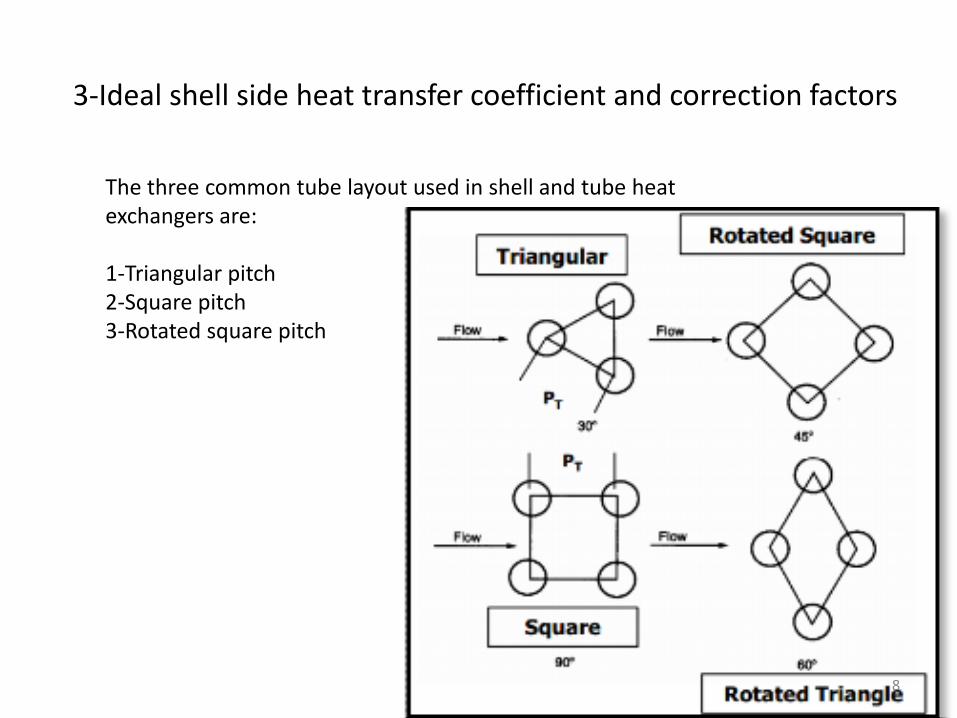
3-Ideal shell side heat transfer coefficient and correction factors
The three common tube layout used in shell and tube heat exchangers are: 1-Triangular pitch 2-Square pitch 3-Rotated square pitch
8

𝜃𝑝 = 30° Pitch angle
3-Ideal shell side heat transfer coefficient and correction factors
9

𝜃𝑝 = 45° Pitch angle 3-Ideal shell side heat transfer coefficient and correction factors
10

𝜃𝑝 = 90 ° Pitch angle
3-Ideal shell side heat transfer coefficient and correction factors
11

𝑗𝑖 = 𝑎11.33
𝑃𝑇 𝑑𝑜
𝑎
𝑅𝑒𝑠𝑎2
𝑎 =𝑎3
1 + 0.14 𝑅𝑒𝑠𝑎4
𝑓𝑖 = 𝑏11.33
𝑃𝑇 𝑑𝑜
𝑏
𝑅𝑒𝑠𝑏2
𝑏 =𝑏3
1 + 0.14 𝑅𝑒𝑠𝑏4
3-Ideal shell side heat transfer coefficient and correction factors
Heat transfer coefficient
Friction coefficient
ℎ𝑖𝑑 = 𝑗𝑖𝐶𝑝𝑠 𝑚
𝐴𝑠𝑃𝑟 −2 3
𝜇𝑠𝜇𝑠,𝑤
0.14
12

Ideal heat transfer and pressure drop factors
13
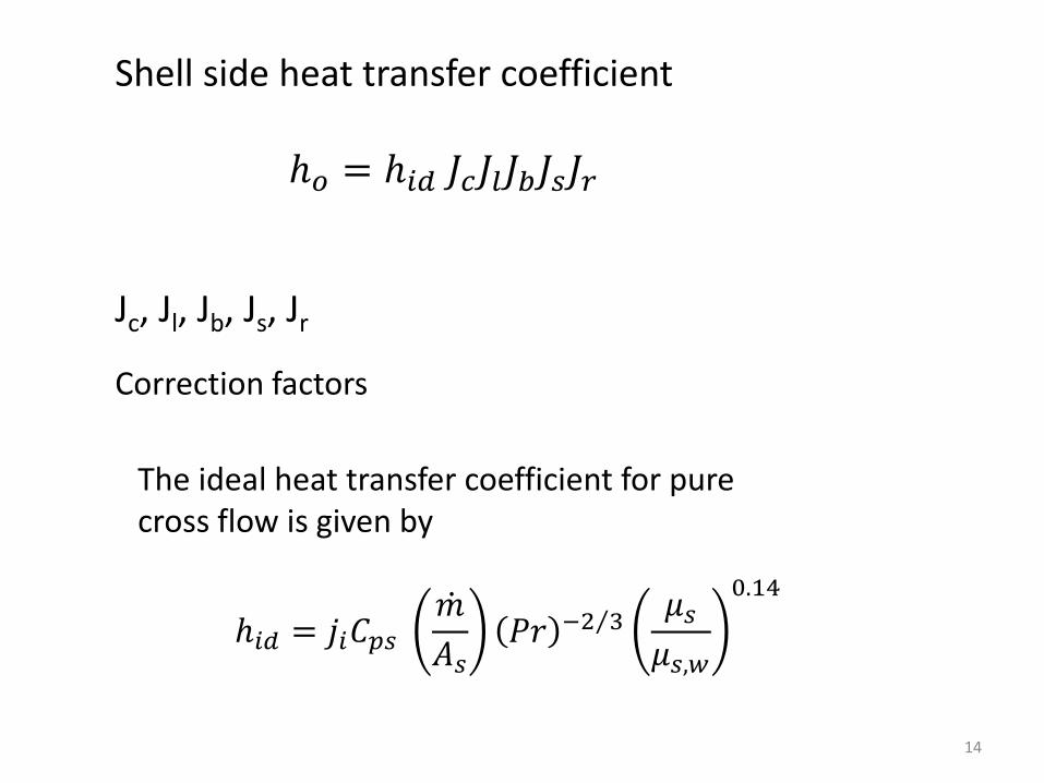
ℎ𝑜 = ℎ𝑖𝑑 𝐽𝑐𝐽𝑙𝐽𝑏𝐽𝑠𝐽𝑟
Shell side heat transfer coefficient
ℎ𝑖𝑑 = 𝑗𝑖𝐶𝑝𝑠 𝑚
𝐴𝑠𝑃𝑟 −2 3
𝜇𝑠𝜇𝑠,𝑤
0.14
Jc, Jl, Jb, Js, Jr
Correction factors
The ideal heat transfer coefficient for pure cross flow is given by
14
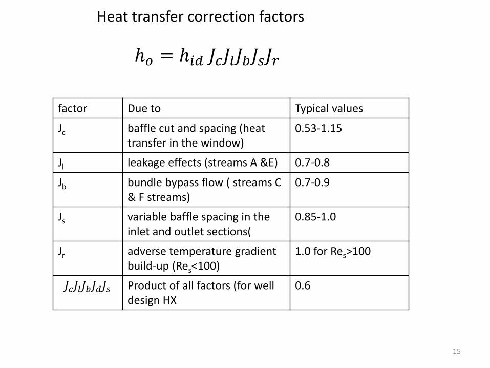
factor Due to Typical values
Jc baffle cut and spacing (heat transfer in the window)
0.53-1.15
Jl leakage effects (streams A &E) 0.7-0.8
Jb bundle bypass flow ( streams C & F streams)
0.7-0.9
Js variable baffle spacing in the inlet and outlet sections(
0.85-1.0
Jr adverse temperature gradient build-up (Res<100)
1.0 for Res>100
𝐽𝑐𝐽𝑙𝐽𝑏𝐽𝑑𝐽𝑠 Product of all factors (for well design HX
0.6
ℎ𝑜 = ℎ𝑖𝑑 𝐽𝑐𝐽𝑙𝐽𝑏𝐽𝑠𝐽𝑟
Heat transfer correction factors
15

𝑅𝑒𝑠 =𝑑𝑜𝑚 𝑠𝜇𝑠𝐴𝑠
𝐴𝑠 = 𝐷𝑠 − 𝑁𝑇𝐶𝑑𝑜 𝐵
𝑁𝑇𝐶 =𝐷𝑠𝑃𝑇
As is the minimum flow area at the shell centerline
NTC number of tubes at the centerline of the shell
𝑅𝑒𝑠 =𝑑𝑜𝑚 𝑠𝜇𝑠𝐴𝑠
Shell side Reynold’s number
Notice that Reynolds number is based on the outside diameter of the tubes
16

Entrance
Internal
Windows
Shell side pressure drop
Δ𝑝𝑐
Δ𝑝𝑤
Δ𝑝𝑒
Δ𝑝𝑠 = Δ𝑝𝑐 + Δ𝑝𝑤 + Δ𝑝𝑒
17

Δ𝑝𝑐 = Δ𝑝𝑏𝑖 𝑁𝑏 − 1 𝑅𝑙𝑅𝑏
Rl leakage correction factor due streams A and C (typical value between 0.4 and 0.5) Rb by pass correction factor due to stream C and F (typical value between 0.5 and 0.8) Nb is the number of baffles
Pressure drop in cross flow between baffle edges
Δ𝑝𝑏𝑖 = 4 𝑓𝑖𝐺𝑠2
2𝜌𝑠 𝜇𝑠,𝑤𝜇𝑠
0.14
18
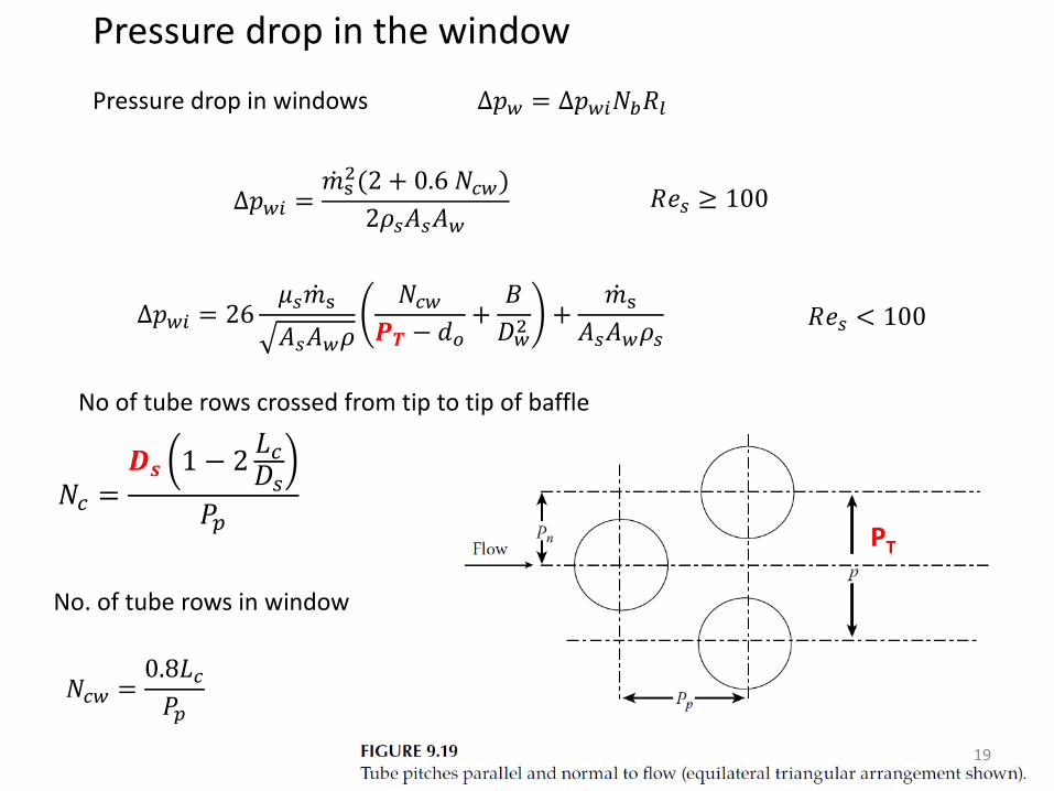
Δ𝑝𝑤 = Δ𝑝𝑤𝑖𝑁𝑏𝑅𝑙 Pressure drop in windows
Pressure drop in the window
Δ𝑝𝑤𝑖 = 26𝜇𝑠𝑚 s
𝐴𝑠𝐴𝑤𝜌
𝑁𝑐𝑤𝑷𝑻 − 𝑑𝑜
+𝐵
𝐷𝑤2 +
𝑚 s𝐴𝑠𝐴𝑤𝜌𝑠
Δ𝑝𝑤𝑖 =𝑚 s
2(2 + 0.6 𝑁𝑐𝑤)
2𝜌𝑠𝐴𝑠𝐴𝑤 𝑅𝑒𝑠 ≥ 100
𝑅𝑒𝑠 < 100
𝑁𝑐 =𝑫𝒔 1 − 2
𝐿𝑐𝐷𝑠
𝑃𝑝
𝑁𝑐𝑤 =0.8𝐿𝑐𝑃𝑝
PT
No of tube rows crossed from tip to tip of baffle
No. of tube rows in window
19

Parallel and normal tube pitch definition
20

Δ𝑝𝑒 = 2Δ𝑝𝑏𝑖𝑁𝑐 +𝑁𝑐𝑤
𝑁𝑐 𝑅𝑏𝑅𝑠 Pressure drop in entrance and exit
Pressure drop at the entrance and exit
Nc is the number of tube rows crossed in the heat exchanger (baffle tip-to-tip) Ncw is the number of tube rows crosses in the window Rs is the correction factor entrance and exit section having different baffle spacing than internal section due existence of inlet and outlet nozzles
Δ𝑝𝑠 = 𝑁𝑏 − 1 Δ𝑝𝑏𝑖𝑅𝑏 + 𝑁𝑏Δ𝑝𝑤𝑖 𝑅𝑙 + 2Δ𝑝𝑏𝑖 1 +𝑁𝑐𝑤𝑁𝑐
𝑅𝑏𝑅𝑠
Total Shell side pressure drop
or
Δ𝑝𝑠 = Δ𝑝𝑐 + Δ𝑝𝑤 + Δ𝑝𝑒
21

Number of baffles
Bi and Bo are the baffle spacing at inlet and exit
𝑁𝑏 =𝐿 − 𝐵𝑖 − 𝐵𝑜
𝐵+ 1
Number of baffles can be calculated using
If Bi=Bo=B then
𝑁𝑏 =𝐿
𝐵− 1
22

23

Example 9.4 continue
𝐴𝑠 = 𝐷𝑠 − 𝑁𝑇𝐶𝑑𝑜 𝐵 𝑁𝑇𝐶 =
𝐷𝑠𝑃𝑇
24

Example 9.4 continue
25

Example 9.4 continue
26

Example 9.4 continue
27

Example 9.4 continue
28

Example 9.4 continue
29

Shell side pressure drop using Kern procedure
Example 9.4 continue
30

Example 9.4 continued
31

32

33

Example 9.5 continue
34

Example 9.5 continue
35

Example 9.5 continue
36

Example 9.5 continue
37

Example 9.5 continue
38

Example 9.5 continued
39

40