mechanical engineering project - retaw research centerretawprojects.com/uploads/report_2.doc · web...
TRANSCRIPT

CHAPTER 1
INTRODUCTION
Narrow track cars are without doubt the future of urban mobility. These cars have a
very short wheel track in comparison to normal cars. Most of the international car
companies have production models and prototype of narrow track cars. Some
examples are Nissan Land Glider, Nissan Pivo, Honda 3R-C, etc.
Such cars are mostly single seated or double seater with back to back seating
configuration. These cars have several advantages:
1) Half the width means half the weight, more rigidity, more access to narrow
roads, easier parking and much quicker transit times.
2) In an electric vehicle, the lighter weight of this much smaller vehicle will help
to enhance torque power characteristics of an electric motor to achieve “linear
acceleration”.
3) At highway cruising speeds, such cars will be using half the frontal area and
half the drag co efficient, plus reduced running losses make for a very energy
efficient vehicle.
All these advantages make the narrow track vehicle so appealing as an alternative to
the car.
Such cars combine the comfort of a car with the functionality of a motor bike. But
these cars have a very important and dangerous drawback. With a very comparatively
narrow track and heights almost equal to normal cars, these cars are very susceptible
to rolling. As of now all such narrow track cars are electrically driven and have a
limited top speed and hence this drawback is comparatively negligible. But sooner or
later these cars will have to get highway cruising speeds. Then this drawback will be
of grave importance.
Our project took shape as an attempt to face this drawback. We thought so if the cars
has the functionality of a motor cycle why not give it the flexibility of a motor cycle.
This gave use to the idea of an auto-tilting car. There has been many tilting body
1
designs in rail but what we have done is not just a body tilting, in it the car tilts as a
whole. Recently there had been some development in making three- wheeled tilting
cars like the carver, but only prototypes or concepts exist in the field of four-wheeled
tilters.
2

CHAPTER 2
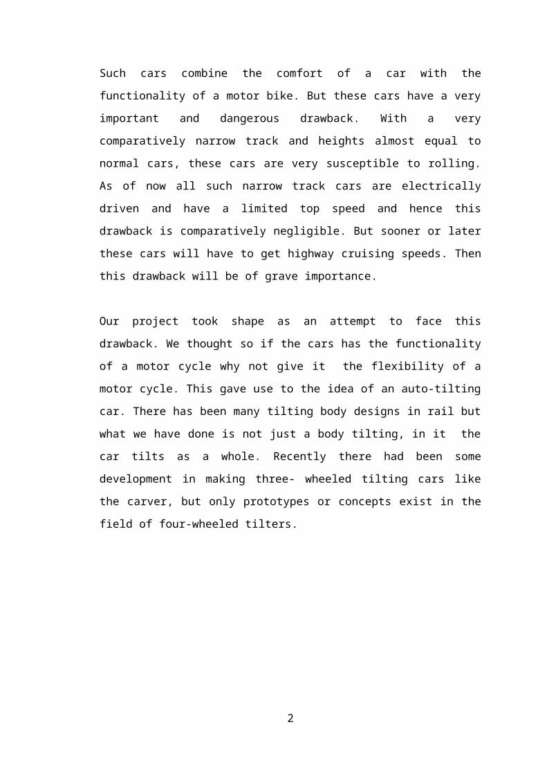
LITERATURE SURVEY‘Narrow track cars’ is not a new term. Several production models do exist and several prototypes are being tried out by major automobile companies. Some production models are Nissan Pivo, Honda 3R-C etcSeveral automobile majors like Toyota, Mercedes, Nissan, Kia, Suzuki etc have prototypes for narrow track cars.
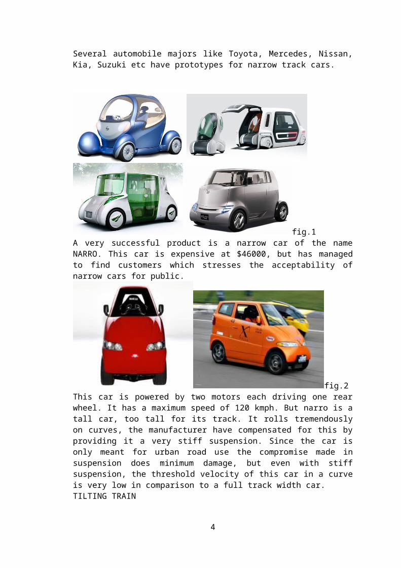
fig.1A very successful product is a narrow car of the name NARRO. This car is expensive at $46000, but has managed to find customers which stresses the acceptability of narrow cars for public.
fig.2This car is powered by two motors each driving one rear wheel. It has a maximum speed of 120 kmph. But narro is a tall car, too tall for its track. It rolls tremendously on curves, the manufacturer have compensated for this by providing it a very stiff suspension. Since the car is only meant for urban road use the compromise made in suspension does minimum damage, but even with stiff suspension, the threshold velocity of this car in a curve is very low in comparison to a full track width car.TILTING TRAINTilting trains are today common in Europe and Japan. These trains are rail-running, they have very high curve velocities. Inorder to enable trains, to negotiate curves at
3
high speeds, tracks are slightly banked (upto 11 degrees). But these trains are too fast, and it is not possible to tilt track beyond a limit because trains also pass along these curves really slowly at times.Tilting trains are an optimum solution for this problem. These types of train, tilts the body on the curve, this in a sort enables faster curve threshold speed and increased passenger comfort. The figure below shows two tilting mechanisms used in trains.
fig.3
fig.4
THREE WHEELED TILTING CARSThese type of cars are a new species, but their number is fast increasing. These cars tilt about their rear wheels. Either there can be two wheels at the rear like the carver. Which has two wheels at the rear and the car body tilts about the rear wheels. Steering is done using front single wheel.
4
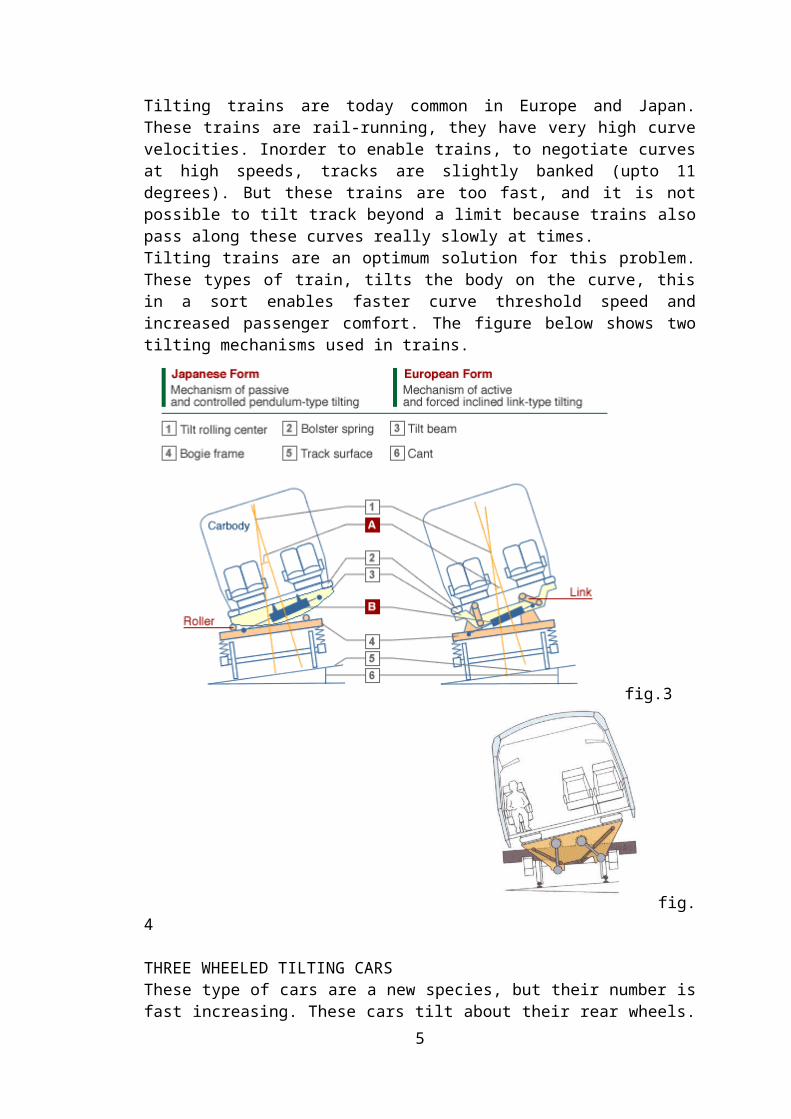
fig.5Or these can be one wheel at the rear about which the body tilts. Like the GTR (Grand Tilting Racer).
fig.6
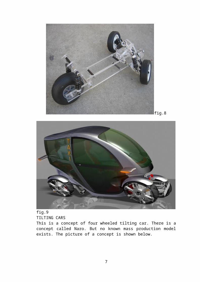
fig7
5
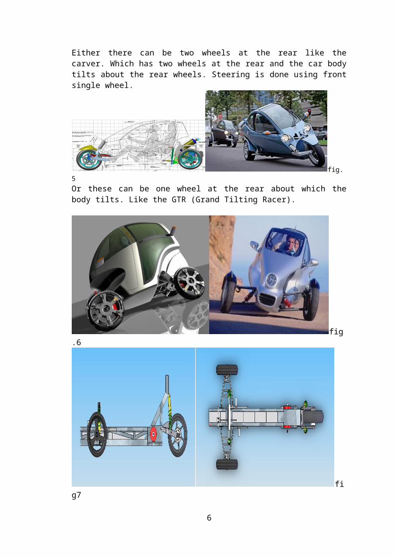
fig.8
fig.9TILTING CARSThis is a concept of four wheeled tilting car. There is a concept called Naro. But no known mass production model exists. The picture of a concept is shown below.
This car is just a concept form and not even a prototype has been made. But expect the research to gain momentum soon.
6
CHAPTER 3
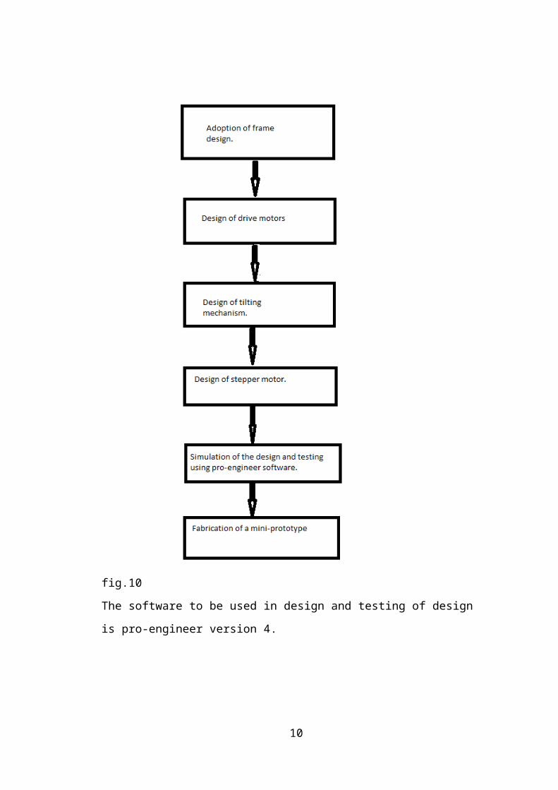
OBJECTIVES & METHODOLOGY
The objective of this project work is to successfully develop a design of a tilting
mechanism for a narrow tilting car. The mechanism is to be reliable, simple, cost-
effective and practically feasible. The aim of this tilting mechanism is to provide
banking to the car on unbanked curves, so as to enable added threshold speed on
curves in comparison to a narrow non-tilting car. This system is also supposed to
enhance passenger comfort as the side force felt by passengers in a car taking a turn is
comparatively less in a tilting car. Also in our purpose is the fabrication of a mini-
prototype –a remote controlled toy car-to demonstrate the tilting in real world.
The methodology adopted to use standard and presently used components in design
rather than to design all components from ground up. The advantage of this method is
that, you do not have to spend ridiculous amount and time in testing the integrity of
each part as they have already proved their worth in real world applications.
Initially the frame design was adopted from an already existing narrow car and minor
changes were made to suite our purpose, the tilting mechanism first devised was
based on using power screw driven by stepper motor lifting and lowering each wheel
of the car. This mechanism was later dropped in testing phase due to following
disadvantages.
1. It had a very large response time, this was not suitable for a car approaching curve
at a very high speed.
2. Wear and tear of screw and contact nut bearing is too high to be satisfactorily used
in a car.
3. The system used four high torque steppers, this along with controls could shoot up
the cost of production .
Due to these disadvantages, the power screw design was dropped and a fully new
design was defined. The prototype car also uses the same tilting mechanism setup.
7
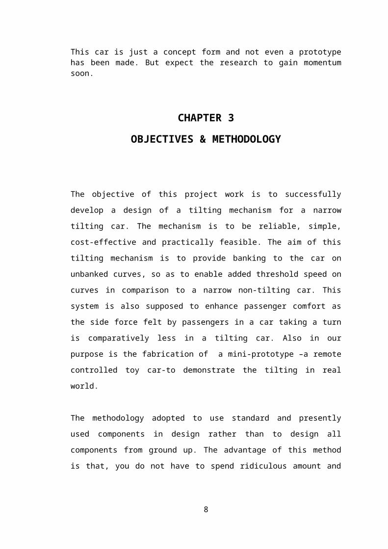
fig.10
The software to be used in design and testing of design is pro-engineer version 4.
Creo Elements/Pro, a product formerly known as Pro/ENGINEER is a parametric,
integrated 3D CAD/CAM/CAE solution created by Parametric Technology
8
Corporation (PTC). It was the first to market with parametric, feature-based,
associative solid modeling software. The application runs on Microsoft Windows and
Unix platforms, and provides solid modeling, assembly modeling and drafting, finite
element analysis, and NC and tooling functionality for mechanical engineers. The
Pro/ENGINEER name was changed to Creo Elements/Pro on October 28, 2010,
coinciding with PTC’s announcement of Creo, a new design software solution.
Summary of capabilities
Like any software it is continually being developed to include new functionality. The
details below aim to outline the scope of capabilities to give an overview rather than
giving specific details on the individual functionality of the product.
Creo Elements/Pro is a software application within the CAID/CAD/CAM/CAE
category, along with other similar products currently on the market.
Creo Elements/Pro is a parametric, feature-based modeling architecture incorporated
into a single database philosophy with advanced rule-based design capabilities. The
capabilities of the product can be split into the three main heading of Engineering
Design, Analysis and Manufacturing. This data is then documented in a standard 2D
production drawing or the 3D drawing standard ASME Y14.41-2003.
Engineering Design
Creo Elements/Pro offers a range of tools to enable the generation of a complete
digital representation of the product being designed. In addition to the general
geometry tools there is also the ability to generate geometry of other integrated design
disciplines such as industrial and standard pipe work and complete wiring definitions.
Tools are also available to support collaborative development.
A number of concept design tools that provide up-front Industrial Design concepts
can then be used in the downstream process of engineering the product. These range
from conceptual Industrial design sketches, reverse engineering with point cloud data
and comprehensive freeform surface tools.
9
Analysis
Creo Elements/Pro has numerous analysis tools available and covers thermal, static,
dynamic and fatigue FEA analysis along with other tools all designed to help with the
development of the product. These tools include human factors, manufacturing
tolerance, mould flow and design optimization. The design optimization can be used
at a geometry level to obtain the optimum design dimensions and in conjunction with
the FEA analysis.
Manufacturing
By using the fundamental abilities of the software with regards to the single data
source principle, it provides a rich set of tools in the manufacturing environment in
the form of tooling design and simulated CNC machining and output.
Tooling options cover specialty tools for molding, die-casting and progressive tooling
design.
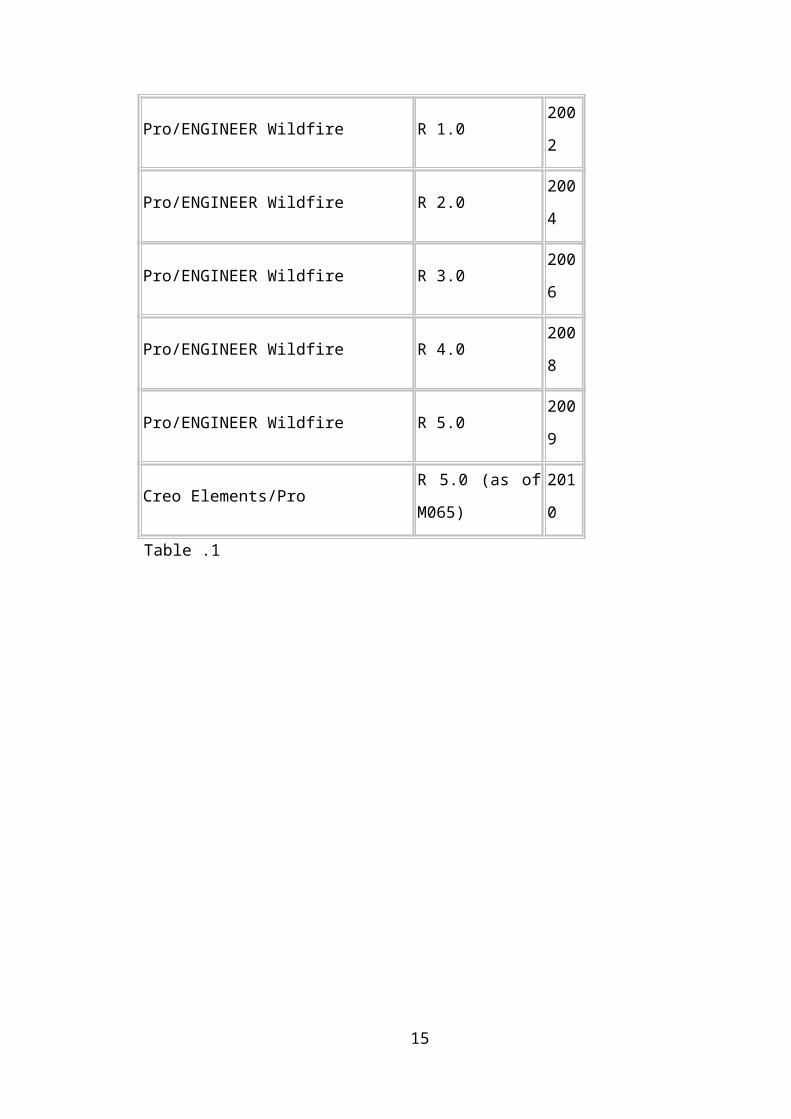
Release history
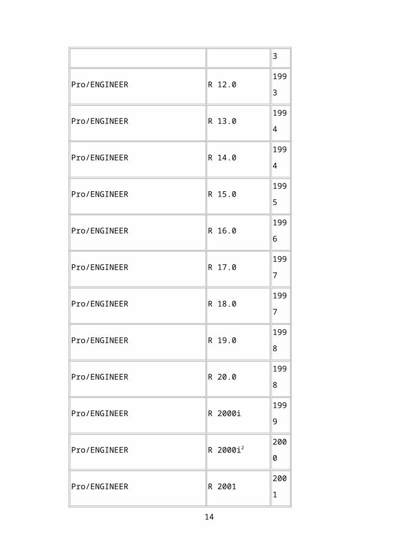
Name/Version Build Number Date
Pro/ENGINEER (Autofact 1987 premier) R 1.0 1987
Pro/ENGINEER R 8.0 1991
Pro/ENGINEER R 9.0 1992
Pro/ENGINEER R 10.0 1993
Pro/ENGINEER R 11.0 1993
Pro/ENGINEER R 12.0 1993
Pro/ENGINEER R 13.0 1994
Pro/ENGINEER R 14.0 1994
Pro/ENGINEER R 15.0 1995
10
Pro/ENGINEER R 16.0 1996
Pro/ENGINEER R 17.0 1997
Pro/ENGINEER R 18.0 1997
Pro/ENGINEER R 19.0 1998
Pro/ENGINEER R 20.0 1998
Pro/ENGINEER R 2000i 1999
Pro/ENGINEER R 2000i2 2000
Pro/ENGINEER R 2001 2001
Pro/ENGINEER Wildfire R 1.0 2002
Pro/ENGINEER Wildfire R 2.0 2004
Pro/ENGINEER Wildfire R 3.0 2006
Pro/ENGINEER Wildfire R 4.0 2008
Pro/ENGINEER Wildfire R 5.0 2009
Creo Elements/Pro R 5.0 (as of M065) 2010
Table .1
11
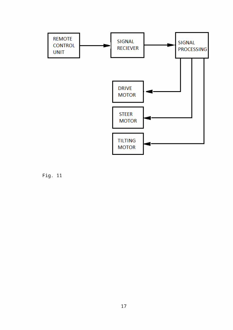
CHAPTER 4
FABRICATION AND DESIGN PROCEDURE
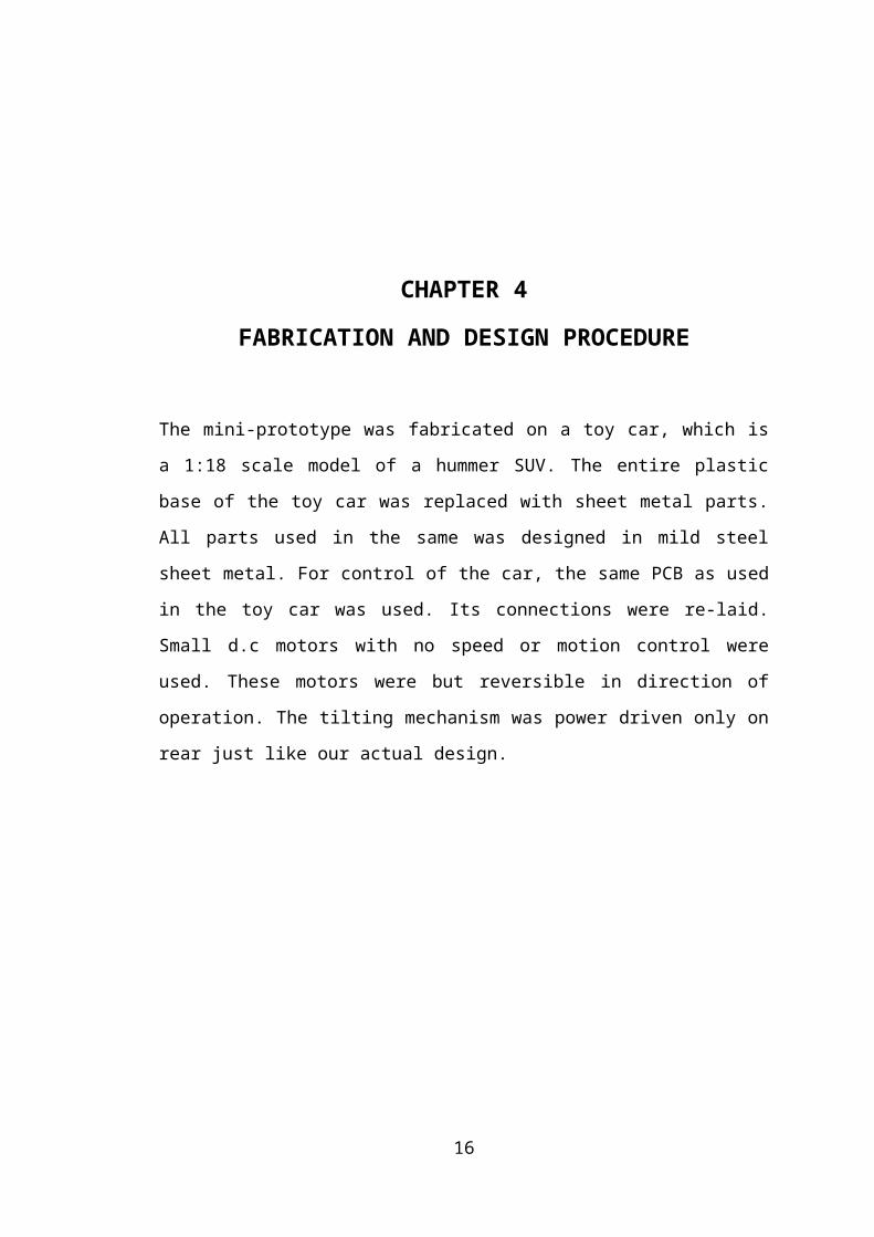
The mini-prototype was fabricated on a toy car, which is a 1:18 scale model of a
hummer SUV. The entire plastic base of the toy car was replaced with sheet metal
parts. All parts used in the same was designed in mild steel sheet metal. For control of
the car, the same PCB as used in the toy car was used. Its connections were re-laid.
Small d.c motors with no speed or motion control were used. These motors were but
reversible in direction of operation. The tilting mechanism was power driven only on
rear just like our actual design.
12
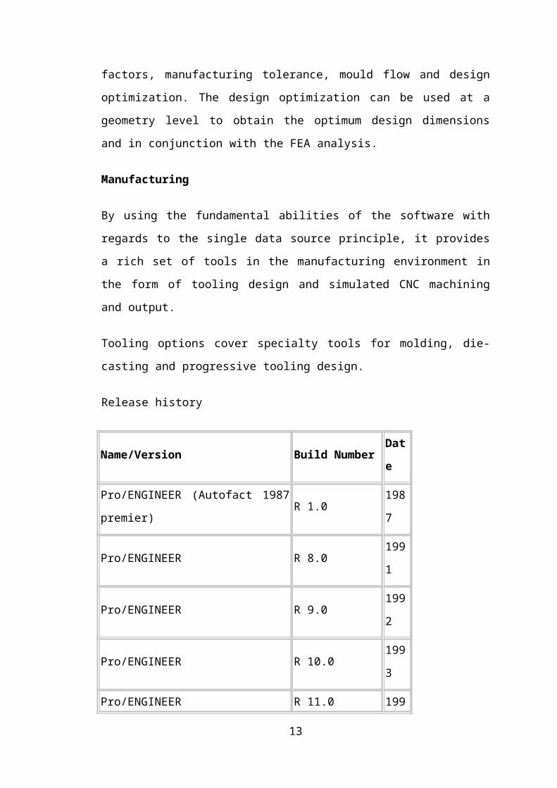
Fig. 11
13
PROCEDURE
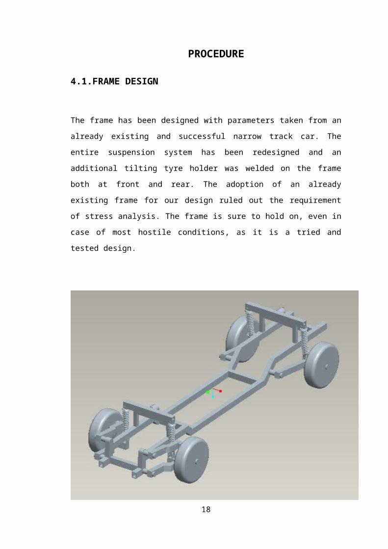
4.1.FRAME DESIGN
The frame has been designed with parameters taken from an already existing and
successful narrow track car. The entire suspension system has been redesigned and an
additional tilting tyre holder was welded on the frame both at front and rear. The
adoption of an already existing frame for our design ruled out the requirement of
stress analysis. The frame is sure to hold on, even in case of most hostile conditions,
as it is a tried and tested design.
Fig 12
14
4.2.DESIGN OF DRIVE MOTOR.In the design of the car we have followed a “no risk policy”, instead of designing all
the parts by ourself. We have used parts already tried and tested in others cars. This is
advocated as we needn’t have to test these already tested parts unnecessarily. Also
these parts are already in use and are satisfactory in their operation. The only new
design is actually the suspension and the tilting mechanism. We have discussed in
detailed all the design details in the coming pages.
In design we have decided to stick to an electrical drive system for the vehicle, though
it is going to be more expensive than oil, it is certainly futuristic and eco-friendly.
Besides, the electrical drive system can be mounted lower and can help to lower the
center of gravity and thus increase the threshold speed at curves.
5.2 DESIGN OF POWER PLANT.
The propulsive power for the vehicle has been decided based on the top speed needed.
It was decided that the vehicle should be able to attain a highway cruising speed of
120 Kmph. So the vehicle must be good for a top speed of atleast 150 Kmph. Hence
the power of propulsion is to be decided in terms of the maximum speed required.
Estimated weight of the car = 650*9.8 = 6370N
PV = (Ra + Rr )*V
Pv is power for propulsion.
Ra =aerodynamic resistance.
Rr =rolling resistance.
V = Speed in kmph.
Rr =(a+bV)*W = 6370*(0.015+0.00016*150) =238.875N
Ra =Ka*A*V2
Ka is aerodynamic co-efficient =.027
A is frontal area = 0.98m2
Ra = 0.027*0.98*1502 = 595.35N
Pv =(595.35 + 91.875)*150/3600 = 34.76hp.
Power required = Pv/efficiency= 34.76/.97 = 35.83hp.
Hence it was decided to use two 20 hp motors of DC brushless type.The motor in
question has a torque of around 800 Nm. These hub motors are already used in some
electric vehicles. The battery that would power the system is of lithium-ion type with
specifications as below.
15
Voltage- 144V, Capacity- 10KWh, Weight- 80kg.
The battery under full charge can provide the vehicle a range of around 100 kms.
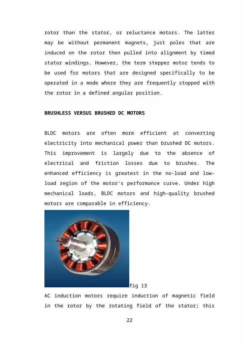
Brushless DC motors (BLDC motors, BL motors) also known as electronically
commutated motors (ECMs, EC motors) are synchronous electric motors powered by
direct-current (DC) electricity and having electronic commutation systems, rather than
mechanical commutators and brushes. The current-to-torque and frequency-to-speed
relationships of BLDC motors are linear.
BLDC motors may be described as stepper motors, with fixed permanent magnets and
possibly more poles on the rotor than the stator, or reluctance motors. The latter may
be without permanent magnets, just poles that are induced on the rotor then pulled
into alignment by timed stator windings. However, the term stepper motor tends to be
used for motors that are designed specifically to be operated in a mode where they are
frequently stopped with the rotor in a defined angular position.
BRUSHLESS VERSUS BRUSHED DC MOTORS
BLDC motors are often more efficient at converting electricity into mechanical power
than brushed DC motors. This improvement is largely due to the absence of electrical
and friction losses due to brushes. The enhanced efficiency is greatest in the no-load
and low-load region of the motor's performance curve. Under high mechanical loads,
BLDC motors and high-quality brushed motors are comparable in efficiency.
fig 13
16
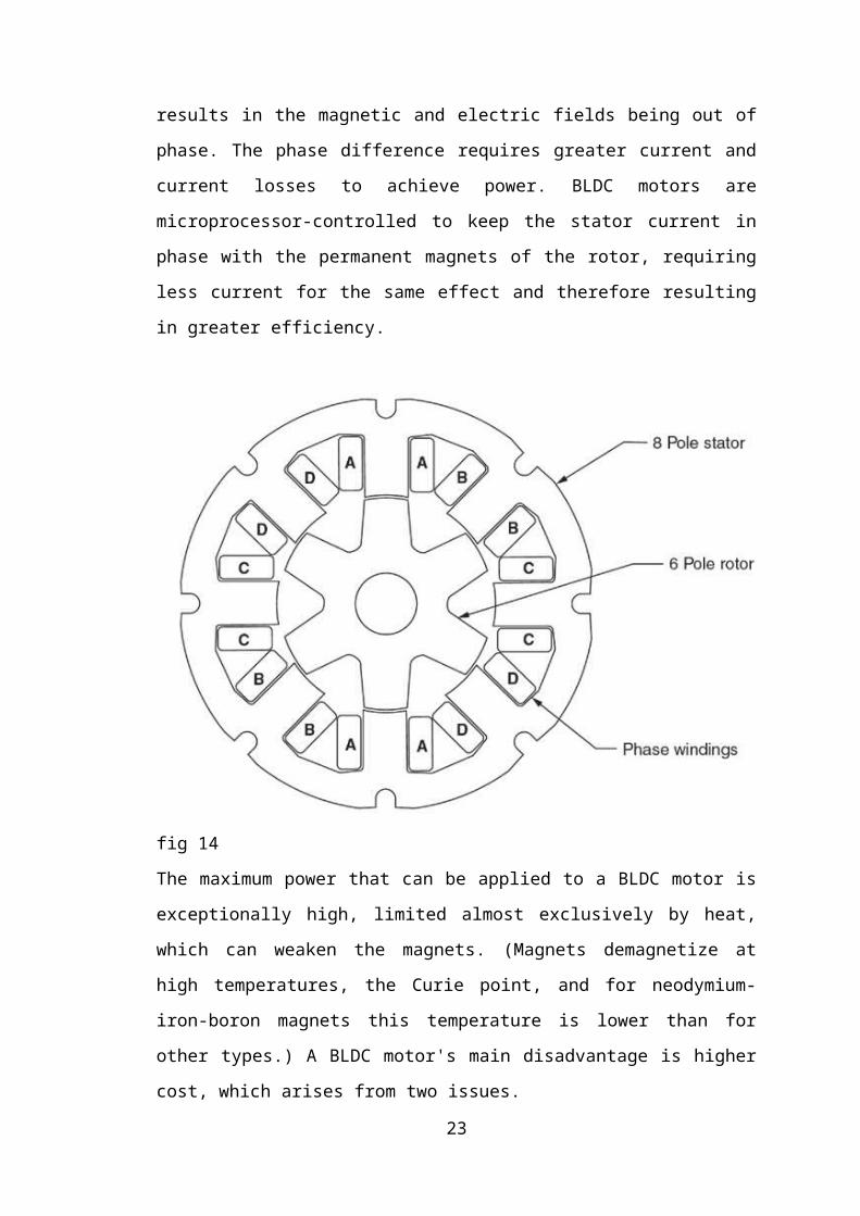
AC induction motors require induction of magnetic field in the rotor by the rotating
field of the stator; this results in the magnetic and electric fields being out of phase.
The phase difference requires greater current and current losses to achieve power.
BLDC motors are microprocessor-controlled to keep the stator current in phase with
the permanent magnets of the rotor, requiring less current for the same effect and
therefore resulting in greater efficiency.
fig 14
The maximum power that can be applied to a BLDC motor is exceptionally high,
limited almost exclusively by heat, which can weaken the magnets. (Magnets
demagnetize at high temperatures, the Curie point, and for neodymium-iron-boron
magnets this temperature is lower than for other types.) A BLDC motor's main
disadvantage is higher cost, which arises from two issues.
17
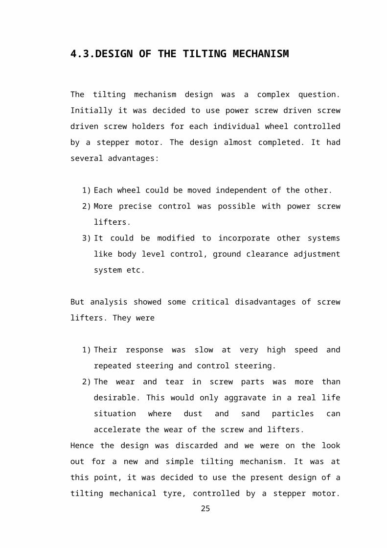
4.3.DESIGN OF THE TILTING MECHANISM
The tilting mechanism design was a complex question. Initially it was decided to use
power screw driven screw driven screw holders for each individual wheel controlled
by a stepper motor. The design almost completed. It had several advantages:
1) Each wheel could be moved independent of the other.
2) More precise control was possible with power screw lifters.
3) It could be modified to incorporate other systems like body level control,
ground clearance adjustment system etc.
But analysis showed some critical disadvantages of screw lifters. They were
1) Their response was slow at very high speed and repeated steering and control
steering.
2) The wear and tear in screw parts was more than desirable. This would only
aggravate in a real life situation where dust and sand particles can accelerate
the wear of the screw and lifters.
Hence the design was discarded and we were on the look out for a new and simple
tilting mechanism. It was at this point, it was decided to use the present design of a
tilting mechanical tyre, controlled by a stepper motor. The ends of the tyre were
linked to each rear wheel through struts as used in bikes rear shocks but with
universal joints on both sides. The tyre is moved about a central pivot mount on the
frame, this motion in result lifts the wheel on one side, while lowering the other, this
in result tilts the vehicle to one side. The reverse motion of the tyre tilts the vehicle in
opposite direction. After much thought and consultation, it was decided to power only
the rear rotating tyre, the front was free and was supposed to follow the rear. This was
adopted not to reduce the cost but it had the following advantages:
1) It provided more freedom of movement to the front wheels, which ensured
better comfort.
2) The freedom of movement of front wheels also give the vehicle added steer
ability and maneavourability.
3) It also reduced the overall weight of the vehicle.
18

fig 15
19
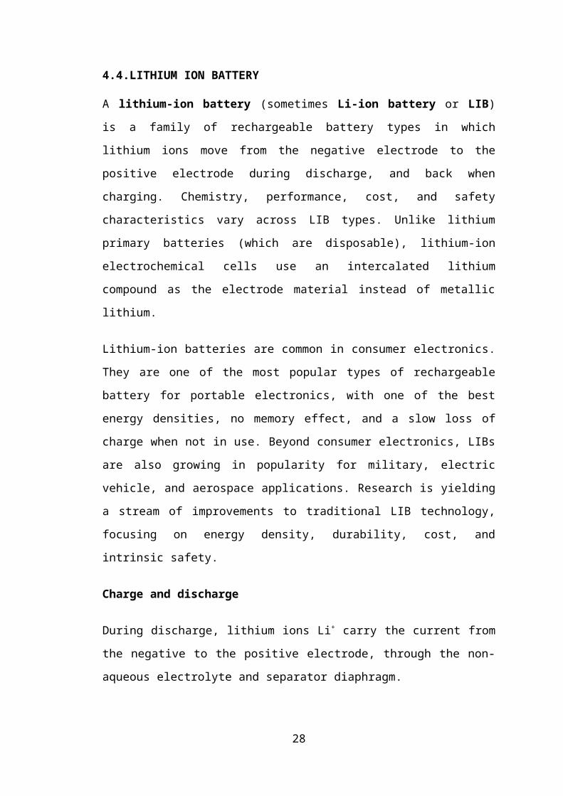
4.4.LITHIUM ION BATTERY
A lithium-ion battery (sometimes Li-ion battery or LIB) is a family of rechargeable
battery types in which lithium ions move from the negative electrode to the positive
electrode during discharge, and back when charging. Chemistry, performance, cost,
and safety characteristics vary across LIB types. Unlike lithium primary batteries
(which are disposable), lithium-ion electrochemical cells use an intercalated lithium
compound as the electrode material instead of metallic lithium.
Lithium-ion batteries are common in consumer electronics. They are one of the most
popular types of rechargeable battery for portable electronics, with one of the best
energy densities, no memory effect, and a slow loss of charge when not in use.
Beyond consumer electronics, LIBs are also growing in popularity for military,
electric vehicle, and aerospace applications. Research is yielding a stream of
improvements to traditional LIB technology, focusing on energy density, durability,
cost, and intrinsic safety.
Charge and discharge
During discharge, lithium ions Li+ carry the current from the negative to the positive
electrode, through the non-aqueous electrolyte and separator diaphragm.
During charging, an external electrical power source (the charging circuit) applies a
higher voltage (but of the same polarity) than that produced by the battery, forcing the
current to pass in the reverse direction. The lithium ions then migrate from the
positive to the negative electrode, where they become embedded in the porous
electrode material in a process known as intercalation.
20
Construction
fig 16
Cylindrical 18650 cell before closing
The three primary functional components of a lithium-ion battery are the anode,
cathode, and electrolyte. The anode of a conventional lithium-ion cell is made from
carbon, the cathode is a metal oxide, and the electrolyte is a lithium salt in an organic
solvent.
The most commercially popular anode material is graphite. The cathode is generally
one of three materials: a layered oxide (such as lithium cobalt oxide), a polyanion
(such as lithium iron phosphate), or a spinel (such as lithium manganese oxide).
The electrolyte is typically a mixture of organic carbonates such as ethylene carbonate
or diethyl carbonate containing complexes of lithium ions. These non-aqueous
electrolytes generally use non-coordinating anion salts such as lithium
hexafluorophosphate (LiPF6), lithium hexafluoroarsenate monohydrate (LiAsF6),
lithium perchlorate (LiClO4), lithium tetrafluoroborate (LiBF4), and lithium triflate
(LiCF3SO3).
Depending on materials choices, the voltage, capacity, life, and safety of a lithium-ion
battery can change dramatically. Recently, novel architectures using nanotechnology
have been employed to improve performance.
Pure lithium is very reactive. It reacts vigorously with water to form lithium
hydroxide and hydrogen gas is liberated. Thus a non-aqueous electrolyte is typically
used, and a sealed container rigidly excludes water from the battery pack.
21
Lithium ion batteries are more expensive than NiCd batteries but operate over a wider
temperature range with higher energy densities, while being smaller and lighter. They
are fragile and so need a protective circuit to limit peak voltages.
Electrochemistry
The three participants in the electrochemical reactions in a lithium-ion battery are the
anode, cathode, and electrolyte.
Both the anode and cathode are materials into which, and from which, lithium can
migrate. During insertion (or intercalation) lithium moves into the electrode. During
the reverse process, extraction (or deintercalation), lithium moves back out. When a
lithium-based cell is discharging, the lithium is extracted from the anode and inserted
into the cathode. When the cell is charging, the reverse occurs.
Useful work can only be extracted if electrons flow through a closed external circuit.
The following equations are in units of moles, making it possible to use the
coefficient x.
The positive electrode half-reaction (with charging being forwards) is:
The negative electrode half-reaction is:
The overall reaction has its limits. Overdischarge supersaturates lithium cobalt oxide,
leading to the production of lithium oxide. possibly by the following irreversible
reaction:
Overcharge up to 5.2 Volts leads to the synthesis of cobalt(IV) oxide, as evidenced by
x-ray diffraction[27]
22
In a lithium-ion battery the lithium ions are transported to and from the cathode or
anode, with the transition metal, cobalt (Co), in LixCoO2 being oxidized from Co3+ to
Co4+ during charging, and reduced from Co4+ to Co3+ during discharge.
Positive electrodes
Electrode material Average potential difference Specific capacity Specific energy
LiCoO2 3.7 V 140 mA·h/g 0.518 kW·h/kg
LiMn2O4 4.0 V 100 mA·h/g 0.400 kW·h/kg
LiNiO2 3.5 V 180 mA·h/g 0.630 kW·h/kg
LiFePO4 3.3 V 150 mA·h/g 0.495 kW·h/kg
Li2FePO4F 3.6 V 115 mA·h/g 0.414 kW·h/kg
LiCo1/3Ni1/3Mn1/3O2 3.6 V 160 mA·h/g 0.576 kW·h/kg
Li(LiaNixMnyCoz)O2 4.2 V 220 mA·h/g 0.920 kW·h/kg
Table 2
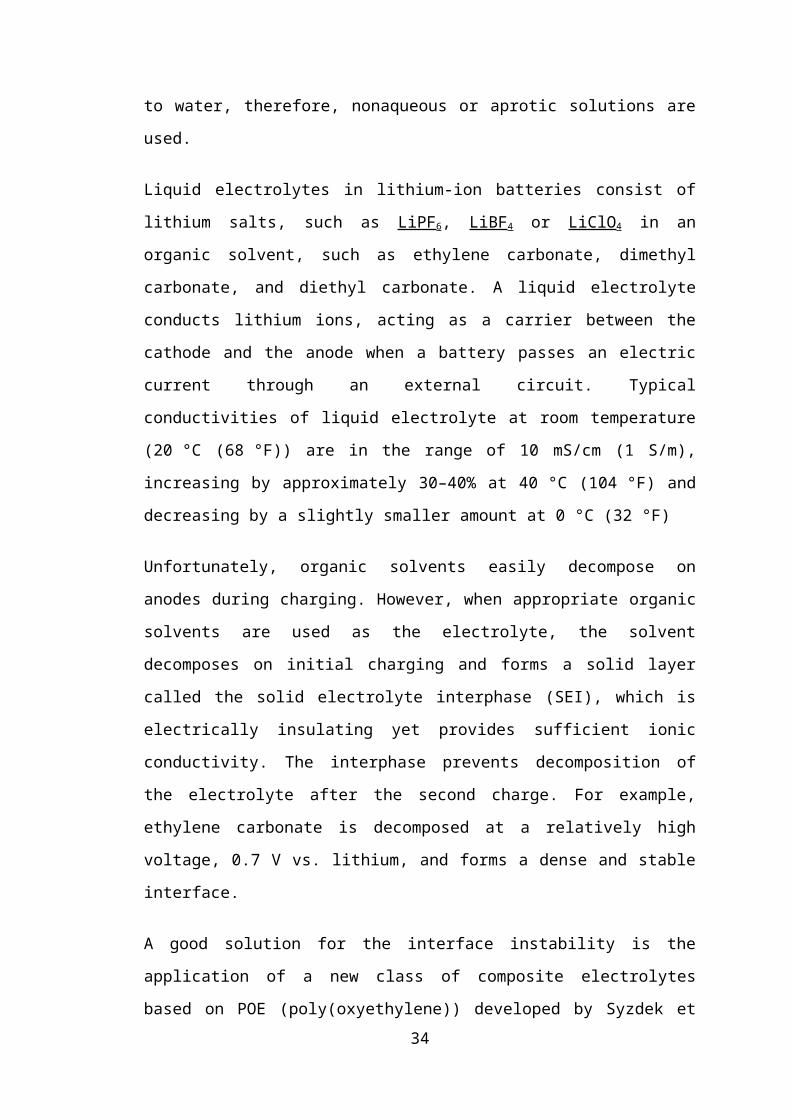
Negative electrodes
Electrode material Average potential difference Specific capacity Specific energy
Graphite (LiC6) 0.1-0.2 V 372 mA·h/g 0.0372-0.0744 kW·h/kg
Hard Carbon (LiC6) ? V ? mA·h/g ? kW·h/kg
Titanate (Li4Ti5O12) 1-2 V 160 mA·h/g 0.16-0.32 kW·h/kg
Si (Li4.4Si) 0.5-1 V 4212 mA·h/g 2.106-4.212 kW·h/kg
Ge (Li4.4Ge) 0.7-1.2 V 1624 mA·h/g 1.137-1.949 kW·h/kg
Table 3
Electrolytes
The cell voltages given in the Electrochemistry section are larger than the potential at
which aqueous solutions can electrolyze, in addition lithium is highly reactive to
water, therefore, nonaqueous or aprotic solutions are used.
Liquid electrolytes in lithium-ion batteries consist of lithium salts, such as LiPF6,
LiBF4 or LiClO4 in an organic solvent, such as ethylene carbonate, dimethyl
carbonate, and diethyl carbonate. A liquid electrolyte conducts lithium ions, acting as
a carrier between the cathode and the anode when a battery passes an electric current
23

through an external circuit. Typical conductivities of liquid electrolyte at room
temperature (20 °C (68 °F)) are in the range of 10 mS/cm (1 S/m), increasing by
approximately 30–40% at 40 °C (104 °F) and decreasing by a slightly smaller amount
at 0 °C (32 °F)
Unfortunately, organic solvents easily decompose on anodes during charging.
However, when appropriate organic solvents are used as the electrolyte, the solvent
decomposes on initial charging and forms a solid layer called the solid electrolyte
interphase (SEI), which is electrically insulating yet provides sufficient ionic
conductivity. The interphase prevents decomposition of the electrolyte after the
second charge. For example, ethylene carbonate is decomposed at a relatively high
voltage, 0.7 V vs. lithium, and forms a dense and stable interface.
A good solution for the interface instability is the application of a new class of
composite electrolytes based on POE (poly(oxyethylene)) developed by Syzdek et al.
It can be either solid (high molecular weight) and be applied in dry Li-polymer cells,
or liquid (low molecular weight) and be applied in regular Li-ion cells.
Another issue that Li-ion technology is facing is safety. Large scale application of Li
cells in Electric Vehicles needs a dramatic decrease in the failure rate. One of the
solutions is the novel technology based on reversed-phase composite electrolytes,
employing porous ceramic material filled with electrolyte.
Advantages and disadvantages
Note that both advantages and disadvantages depend on the materials and design that
make up the battery. This summary reflects older designs that use carbon anode, metal
oxide cathodes, and lithium salt in an organic solvent for the electrolyte.
Advantages
fig 17
24
A lithium-ion battery from a laptop computer
Wide variety of shapes and sizes efficiently fitting the devices they power.
Much lighter than other energy-equivalent secondary batteries.
High open circuit voltage in comparison to aqueous batteries (such as lead
acid, nickel-metal hydride and nickel-cadmium). This is beneficial because it
increases the amount of power that can be transferred at a lower current.
No memory effect.
Self-discharge rate of approximately 5-10% per month, compared to over 30%
per month in common nickel metal hydride batteries, approximately 1.25% per
month for Low Self-Discharge NiMH batteries and 10% per month in nickel-
cadmium batteries.[37] According to one manufacturer, lithium-ion cells (and,
accordingly, "dumb" lithium-ion batteries) do not have any self-discharge in
the usual meaning of this word.[25] What looks like a self-discharge in these
batteries is a permanent loss of capacity (see Disadvantages). On the other
hand, "smart" lithium-ion batteries do self-discharge, due to the drain of the
built-in voltage monitoring circuit.
Components are environmentally safe as there is no free lithium metal.
Disadvantages
Cell life
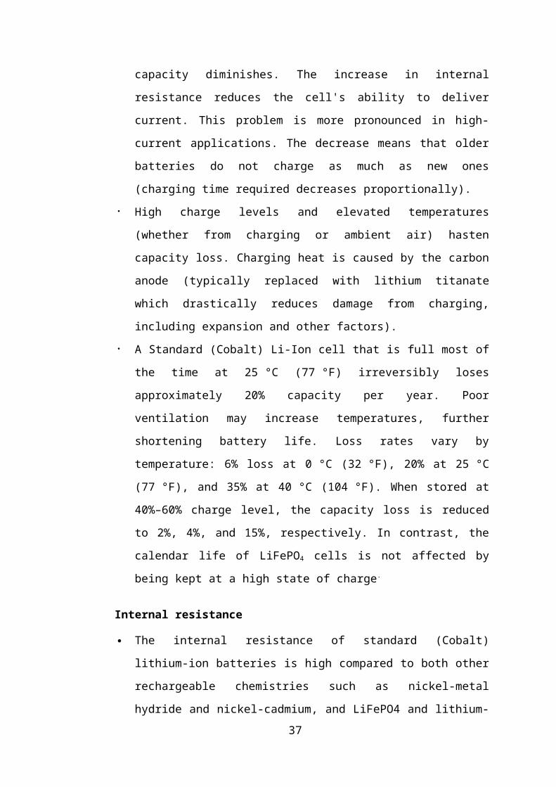
Charging forms deposits inside the electrolyte that inhibit ion transport. Over
time, the cell's capacity diminishes. The increase in internal resistance reduces
the cell's ability to deliver current. This problem is more pronounced in high-
current applications. The decrease means that older batteries do not charge as
much as new ones (charging time required decreases proportionally).
High charge levels and elevated temperatures (whether from charging or
ambient air) hasten capacity loss. Charging heat is caused by the carbon anode
(typically replaced with lithium titanate which drastically reduces damage
from charging, including expansion and other factors).
A Standard (Cobalt) Li-Ion cell that is full most of the time at 25 °C (77 °F)
irreversibly loses approximately 20% capacity per year. Poor ventilation may
increase temperatures, further shortening battery life. Loss rates vary by
25
temperature: 6% loss at 0 °C (32 °F), 20% at 25 °C (77 °F), and 35% at 40 °C
(104 °F). When stored at 40%–60% charge level, the capacity loss is reduced
to 2%, 4%, and 15%, respectively. In contrast, the calendar life of LiFePO4
cells is not affected by being kept at a high state of charge.
Internal resistance
The internal resistance of standard (Cobalt) lithium-ion batteries is high
compared to both other rechargeable chemistries such as nickel-metal hydride
and nickel-cadmium, and LiFePO4 and lithium-polymer cells. Internal
resistance increases with both cycling and age. Rising internal resistance
causes the voltage at the terminals to drop under load, which reduces the
maximum current draw. Eventually increasing resistance means that the
battery can no longer operate for an adequate period.
To power larger devices, such as electric cars, connecting many small batteries
in a parallel circuit is more effective and efficient than connecting a single
large battery.
Safety requirements
If overheated or overcharged Li-ion batteries may suffer thermal runaway and cell
rupture In extreme cases this can lead to combustion. Deep discharge may short-
circuit the cell, in which case recharging would be unsafe.[49] To reduce these risks,
Lithium-ion battery packs contain fail-safe circuity that shuts down the battery when
its voltage is outside the safe range of 3–4.2 V per cell.\ When stored for long periods
the small current draw of the protection circuitry itself may drain the battery below its
shut down voltage; normal chargers are then ineffective. Many types of lithium-ion
cell cannot be charged safely below 0°C.
Other safety features are required in each cell:
shut-down separator (for overtemperature)
tear-away tab (for internal pressure)
vent (pressure relief)
thermal interrupt (overcurrent/overcharging)
26
These devices occupy useful space inside the cells, add additional points of failure
and irreversibly disable the cell when activated. They are required because the anode
produces heat during use, while the cathode may produce oxygen. These devices and
improved electrode designs reduce/eliminate the risk of fire or explosion.
These safety features increase costs compared to nickel metal hydride batteries, which
require only a hydrogen/oxygen recombination device (preventing damage due to
mild overcharging) and a back-up pressure valve.[37]
Specifications and design
Specific energy density: 150 to 250 W·h/kg (540 to 900 kJ/kg)[1]
Volumetric energy density: 250 to 620 W·h/l (900 to 1900 J/cm³)[2]
Specific power density: 300 to 1500 W/kg (@ 20 seconds and 285 W·h/l)[1]
Because lithium-ion batteries can have a variety of cathode and anode materials, the
energy density and voltage vary accordingly.
Lithium-ion batteries with a lithium iron phosphate cathode and graphite anode have a
nominal open-circuit voltage of 3.2 V and a typical charging voltage of 3.6 V.
Lithium nickel manganese cobalt (NMC) oxide cathode with graphite anodes have a
3.7 V nominal voltage with a 4.2 V max charge. The charging procedure is performed
at constant voltage with current-limiting circuitry (i.e., charging with constant current
until a voltage of 4.2 V is reached in the cell and continuing with a constant voltage
applied until the current drops close to zero). Typically, the charge is terminated at
3% of the initial charge current. In the past, lithium-ion batteries could not be fast-
charged and needed at least two hours to fully charge. Current-generation cells can be
fully charged in 45 minutes or less. Some lithium-ion varieties can reach 90% in as
little as 10 minutes.
27
4.5.STEPPER MOTOR DESIGN
For tilting the vehicle by 20 degree each side should be able to move up and down by
at least 13 cms .
fig 18
This gives the total rotational measure for the stepper motor i.e. 64.13 degree in all.
The stepper motor is to be controlled by a microprocessor based on inputs from the
following types of sensors.
1) Speed of sensor
2) Steering position sensor
3) Yaw rate sensor
4) Level sensor
The signal to the stepper motor is generated in proportion to the speed of the vehicle.
The signal is given to the motor based on the steering position. The level position
sensor senses if the road is already banked, it then adjusts the signal accordingly so
that the vehicle does not over tilt at any point.
28
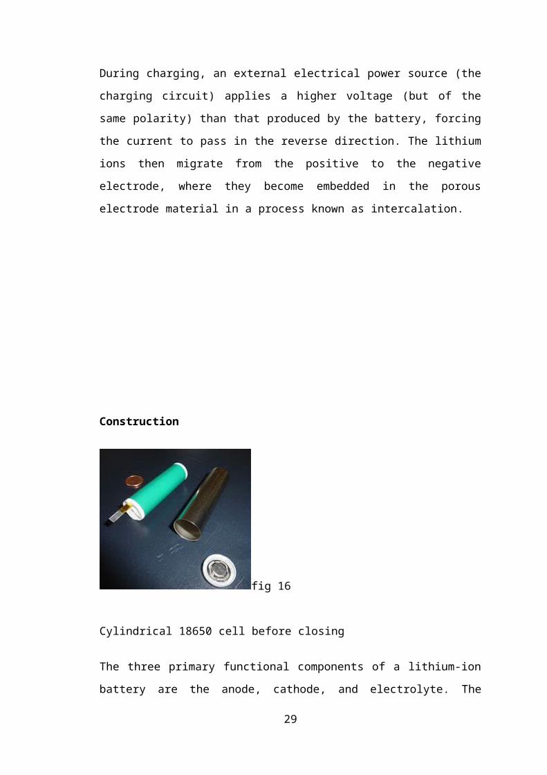
fig 19
A stepper motor (or step motor) is a brushless, synchronous electric motor that can
divide a full rotation into a large number of steps. The motor's position can be
controlled precisely without any feedback mechanism (see Open-loop controller), as
long as the motor is carefully sized to the application. Stepper motors are similar to
switched reluctance motors (which are very large stepping motors with a reduced pole
count, and generally are closed-loop commutated.)
fig 20
Stepper motors operate differently from DC brush motors, which rotate when voltage
is applied to their terminals. Stepper motors, on the other hand, effectively have
multiple "toothed" electromagnets arranged around a central gear-shaped piece of
iron. The electromagnets are energized by an external control circuit, such as a
microcontroller. To make the motor shaft turn, first one electromagnet is given power,
which makes the gear's teeth magnetically attracted to the electromagnet's teeth.
29
When the gear's teeth are thus aligned to the first electromagnet, they are slightly
offset from the next electromagnet. So when the next electromagnet is turned on and
the first is turned off, the gear rotates slightly to align with the next one, and from
there the process is repeated. Each of those slight rotations is called a "step", with an
integer number of steps making a full rotation. In that way, the motor can be turned by
a precise angle.
Fig 21
A unipolar stepper motor has two windings per phase, one for each direction of
magnetic field. Since in this arrangement a magnetic pole can be reversed without
switching the direction of current, the commutation circuit can be made very simple
(e.g. a single transistor) for each winding. Typically, given a phase, one end of each
winding is made common: giving three leads per phase and six leads for a typical two
phase motor. Often, these two phase commons are internally joined, so the motor has
only five leads.
A microcontroller or stepper motor controller can be used to activate the drive
transistors in the right order, and this ease of operation makes unipolar motors popular
with hobbyists; they are probably the cheapest way to get precise angular movements.
30
fig 22
fig 23
31
CHAPTER 5
TESTING OF DESIGNThe designed tilting mechanism has been recreated and tested in pro-e simulation
program. Initially, the tyre resisted movement and after many rounds of fine-tuning
the dimensions, the assembly began to show positive results. Only the rear rotating
tyre had to be tested as the front was not under powered motion. The front rotating
tyre assembly was also dimensionally modified to suite the rear one. Certain range of
motion was imparted to the rear rotating tyre and the process was captured as a video
for presentation. The complete frame design with final dimensions is:
fi
g 24
32
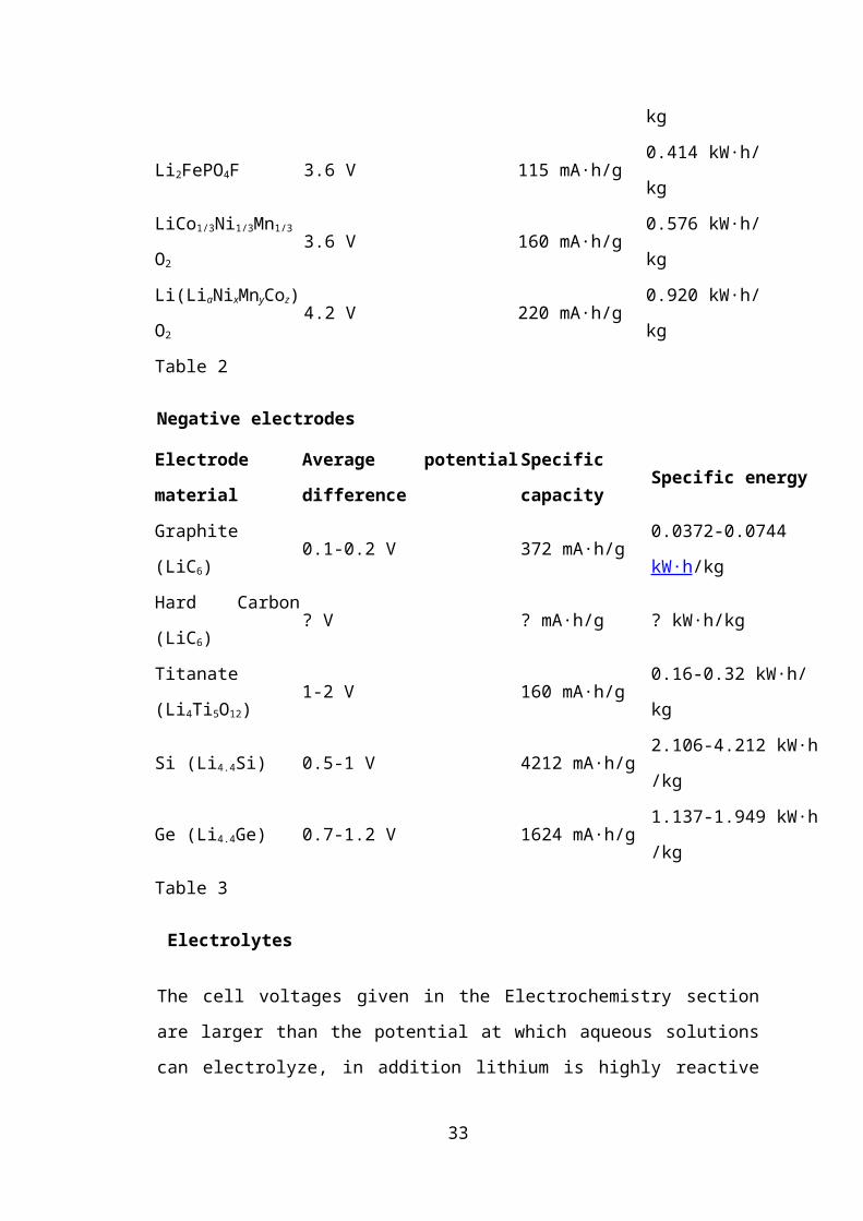
Fig 25
33
5.2. ADVANTAGES OF NARROW TILTING CAR
Several of the advantages of our design over conventional car was discussed
previously. They are summarized below:
1) This car is much more efficient than a conventional gasoline car due to
reduced aerodynamic drag at cruising speed due to reduced frontal area.
2) This design combines the utility of a car with the flexibility of motor bike.
3) Narrow track cars are definitely future of urban mobility, but our tilting car
can also handle highway cruising as well.
4) Like any other electric car, it is cheap to run and environment friendly.
5) It is also likely to be a solution to real day traffic congestion.
34
5.3.COMPARISON OF THRESHOLD VELOCITY ON CURVES FOR
TILTING AND NON-TILTING CARS
From equations of vehicle dynamics, for a vehicle in a curve
Maximum sliding velocity, Vs2 =gC(sinθ +µcosθ)/(cosθ + µsinθ)
Maximum overturning velocity, Vo2 =gC(a cosθ +2h sinθ)/(2h cosθ – a sinθ)
For a non-tilting car under the following parameters
fig 26
µ=0.6
θ=200
C=50m
g=9.8m/s2
a=0.71m
h=0.68m
Sliding velocity for non-tilting car =17.14m/s =61.7kmph
Overturning velocity for the same =15.99m/s =57.56kmph
Whereas for a tilting car that can tilt 20 degrees into the curve,
Sliding velocity = 24.58m/s =88.48kmph
Overturning velocity = 82.86kmph
Increase in sliding velocity = 43.4%
Increase in overturning velocity =43.9%
35
5.4.CONCLUSION
It can be seen from the above result that, our objective to increase the threshold
velocity of a narrow car in a curve has been successful. The design of the car and
tilting mechanism worked flawlessly in simulation as well. The mini-prototype to
demonstrate tilting is also working successfully, all these facts point to the
completion of our objective in high esteem.
5.4.1.ESTIMATES FOR ACTUAL PRODUCTION
1) Lithium ion battery = 40,000
2) Stepper motor and controls =37,000+40000
3) Frame and body fabrication =1, 00, 000
4) DC Brushless hub type drive motors 20 hp each
=2*18000=36000+14000=50000
5) Upholstery =15,000
6) Accessories = 20,000
7) Total = 302000
5.5.FUTURE DEVELOPMENTS
1.The car design in itself is futuristic and can be soon find in some production
versions of four-wheeled tilting cars.
2. A feature can be added to the existing suspension using a minor programming
change, the system can also act as body leveler in transverse direction using the level
sensor, this feature enables added gradability in sideward direction.
36
REFERENCE
1) Salim Maakaroun, Wasima Khali GEOMETRIC MODEL OF A NARROW
TILTING CAR USING ROBOTIC FORMALISM.
Salim Maakaroun, Wasima Khalil.
2) Gohl J, Rajamani R Development of a novel tilting controlled narrow commuter
vehicle (internal report May 2006)
3) Rajamani R Vehicle Dynamics and control
4) N.K. Giri-Automobile Mechanics. Khanna publications
5) Kirpal singh-Automobile Technology
6) Suspension Bible . Chris Longhurst
7) www.design911.com
37