mechanical loss and deposition of mirror coatings on silica
TRANSCRIPT

1
Mechanical Loss and Deposition of Mirror Coatings on Silica
A. E. Turner1, P. G. Murray2, R. Robie2, and I. W. Martin2 1 Department of Physics, St. Olaf College, Northfield 55441, USA 2 SUPA, School of Physics and Astronomy, University of Glasgow, Glasgow G12 8QQ, UK
Abstract
The sensitivity of ground based interferometric gravitational wave detectors is limited by thermal noise caused by mechanical dissipation in the mirror coatings. To reduce this noise, different coatings and deposition techniques are currently being researched. Here, we present the mechanical loss of alumina (Al2O3), silica (SiO2), amorphous silicon (aSi), tantala (Ta2O5), and titania (TiO2) coatings deposited on fused silica cantilevers at room temperature. The mechanical loss of these coatings was measured over a range of resonant bending modes using the ring-down method. Tantala coatings doped with different amounts of titania, a currently used composite in LIGO, were observed to have the minimum mechanical loss with 52% titania doped tantala. We will then discuss the benefits of an amorphous silicon and silica bilayer coating. Then, we compare different deposition methods, finding that ion-plating may be a new viable deposition method. Next, the energy of the beam used in the deposition process causes the coating to react to heat treatment differently. The mechanical loss decreases until the coating begins to crystallize. Furthermore, we compare the loss of alumina coatings of different thicknesses, proving that the thickness of a coating does not affect the calculated mechanical loss.
1 Introduction Einstein predicted in his General Theory of Relativity that asymmetric accelerations of masses would cause ripples through space-time, otherwise known as gravitational waves [1]. Scientists have attempted to measure these gravitational waves with devices such as the bar detector but have, as yet, not been successful. These waves travel at the speed of light and only invoke miniscule strains in space-time. Ground based interferometric gravitational wave detectors were built to improve detection sensitivity, focusing on large astronomical gravitation events.

2
Unfortunately, these detectors, located on three separate continents of the world, have yet to simultaneously detect a gravitational wave due to the sensitivity limitations of the current generation of gravitational wave detectors.
Figure 1.1: A schematic diagram of a ground based interferometric gravitational wave detector, based on a Michelson interferometer. Top: How an optimally oriented passing gravitational wave is expected to interact with the interferometer [14].
Interferometric gravitational wave detectors are high precision tools built to detect the
subtle changes of mass positions due to gravitational waves. As of now, these detectors are limited mainly by seismic, Newtonian, thermal and quantum noise [1]. Mirror coatings in these interferometers generate a significant level of thermal noise. The ion-beam sputtered amorphous oxide mirror coatings currently used in these detectors will soon limit the sensitivities of upgrades to gravitational wave detectors. In order to reduce this thermal noise, it has been proposed to cool the mirrors to cryogenic temperatures. Reduced operating temperatures may help lower the thermoelastic dissipation of the coatings. Moreover, at cryogenic temperatures both tantala and silica, the materials used in current gravitational wave detectors, exhibit an increase in mechanical loss implying that the gains from cooling the coatings disappear due to the amplification of mechanical loss. [7]
Unfortunately, upgrading gravitational detectors to cryogenic temperatures will take several years and a considerable amount of further research, as well as significant changes in
3
infrastructure. There will likely be an intermediate model between current and cryogenic detectors. This model will include many developments involving the suspension systems, coatings, laser and control electronics. Therefore, understanding coating material properties at room temperature is vital for this intermediate step.
(a)
(b)
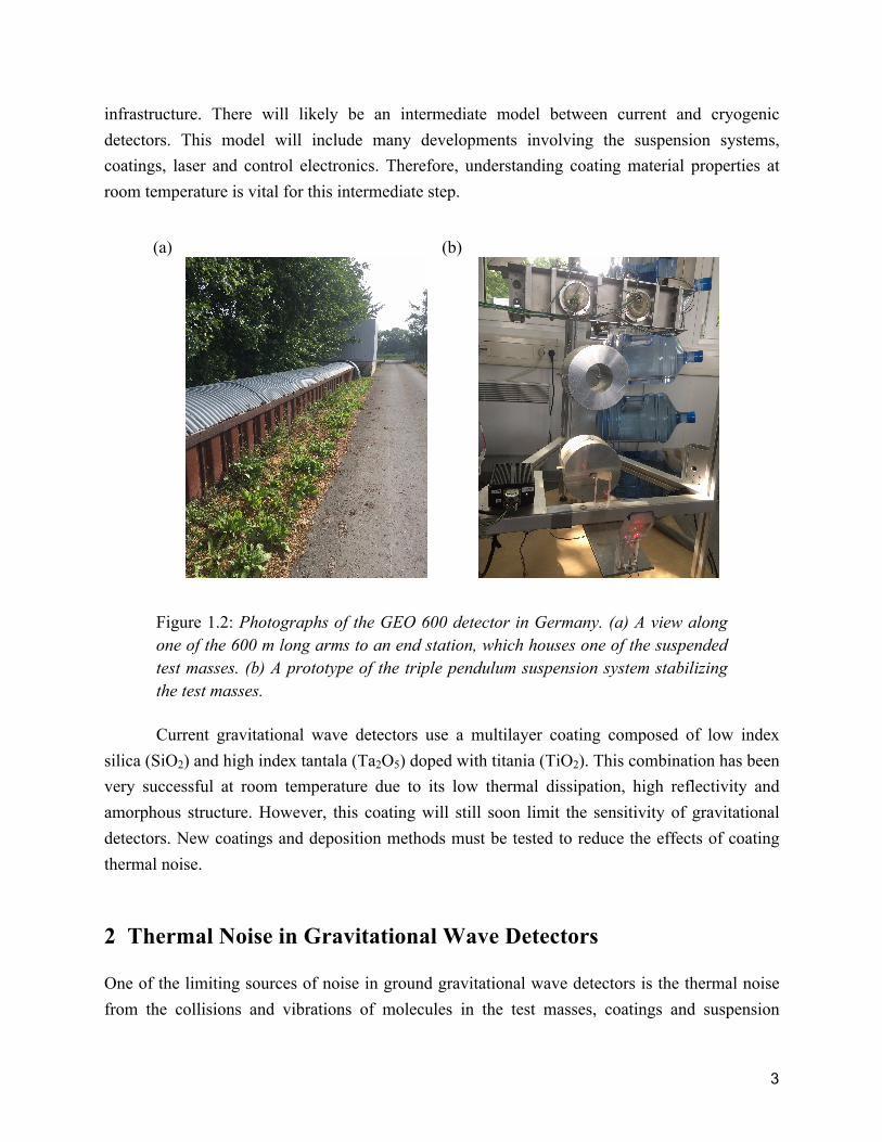
Figure 1.2: Photographs of the GEO 600 detector in Germany. (a) A view along one of the 600 m long arms to an end station, which houses one of the suspended test masses. (b) A prototype of the triple pendulum suspension system stabilizing the test masses.
Current gravitational wave detectors use a multilayer coating composed of low index silica (SiO2) and high index tantala (Ta2O5) doped with titania (TiO2). This combination has been very successful at room temperature due to its low thermal dissipation, high reflectivity and amorphous structure. However, this coating will still soon limit the sensitivity of gravitational detectors. New coatings and deposition methods must be tested to reduce the effects of coating thermal noise.
2 Thermal Noise in Gravitational Wave Detectors One of the limiting sources of noise in ground gravitational wave detectors is the thermal noise from the collisions and vibrations of molecules in the test masses, coatings and suspension

4
systems. In order to minimize this noise, two categories of thermal noise must be considered: mechanical dissipation and thermoelastic noise.
2.1 Mechanical Dissipation
Mechanical dissipation in ground based gravitational wave detectors comes in two categories, external and internal dissipation. External mechanical dissipation is the flow of energy out of the system into the environment, which can be minimized by altering the environment itself. For example, gas damping (which will be discussed further in Section 3.4) can greatly affect the noise of a gravitational system, which is why gravitational detectors run in ultra-low vacuum. Internal dissipation causes the system to heat as a result of molecular friction. When external dissipation is minimized, internal dissipation mechanisms prevail. Therefore, finding the best mirror coating material that minimizes internal mechanical dissipation is essential for high sensitivity measurements in gravitational wave detection.
Internal mechanical dissipation comes from internal friction or molecular friction. If a material were perfect, stress applied on the solid would instantaneously cause there to be strain within the material. But this is not physically accurate. When stress is applied on a material, the strain felt within the material has a time lag. The phase shift between the stress and strain causes energy to be dissipated within the material in the form of heat. 2.2 Thermoelastic Noise Heat flow within a coating or material can also cause dissipation of energy. At the resonant modes of materials, they will maximally oscillate, causing one side of the material to compress and the opposite side to stretch. The compressed side heats and the stretched side cools. As the material oscillates, the temperature of a single side of the material oscillates as well. This heat transfer causes some dissipation of energy.
5
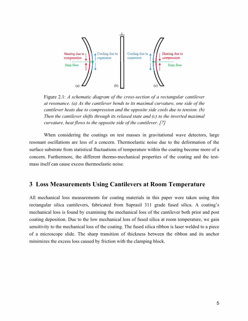
Figure 2.1: A schematic diagram of the cross-section of a rectangular cantilever at resonance. (a) As the cantilever bends to its maximal curvature, one side of the cantilever heats due to compression and the opposite side cools due to tension. (b) Then the cantilever shifts through its relaxed state and (c) to the inverted maximal curvature, heat flows to the opposite side of the cantilever. [7]
When considering the coatings on test masses in gravitational wave detectors, large resonant oscillations are less of a concern. Thermoelastic noise due to the deformation of the surface substrate from statistical fluctuations of temperature within the coating become more of a concern. Furthermore, the different thermo-mechanical properties of the coating and the test-mass itself can cause excess thermoelastic noise.
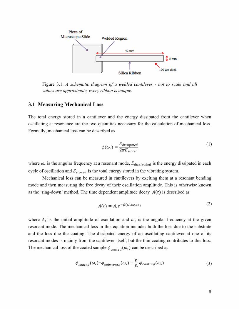
3 Loss Measurements Using Cantilevers at Room Temperature All mechanical loss measurements for coating materials in this paper were taken using thin rectangular silica cantilevers, fabricated from Suprasil 311 grade fused silica. A coating’s mechanical loss is found by examining the mechanical loss of the cantilever both prior and post coating deposition. Due to the low mechanical loss of fused silica at room temperature, we gain sensitivity to the mechanical loss of the coating. The fused silica ribbon is laser welded to a piece of a microscope slide. The sharp transition of thickness between the ribbon and its anchor minimizes the excess loss caused by friction with the clamping block.
6
Figure 3.1: A schematic diagram of a welded cantilever - not to scale and all values are approximate, every ribbon is unique.
3.1 Measuring Mechanical Loss The total energy stored in a cantilever and the energy dissipated from the cantilever when oscillating at resonance are the two quantities necessary for the calculation of mechanical loss. Formally, mechanical loss can be described as
𝜙 𝜔∘ =𝐸𝑑𝑖𝑠𝑠𝑖𝑝𝑎𝑡𝑒𝑑2𝜋𝐸𝑠𝑡𝑜𝑟𝑒𝑑
where 𝜔∘ is the angular frequency at a resonant mode, 𝐸!"##"$%&'! is the energy dissipated in each cycle of oscillation and 𝐸!"#$%& is the total energy stored in the vibrating system. Mechanical loss can be measured in cantilevers by exciting them at a resonant bending mode and then measuring the free decay of their oscillation amplitude. This is otherwise known as the ‘ring-down’ method. The time dependent amplitude decay 𝐴(𝑡) is described as
𝐴(𝑡) = 𝐴∘𝑒!!(!∘)!∘!/!
where 𝐴∘ is the initial amplitude of oscillation and 𝜔∘ is the angular frequency at the given resonant mode. The mechanical loss in this equation includes both the loss due to the substrate and the loss due the coating. The dissipated energy of an oscillating cantilever at one of its resonant modes is mainly from the cantilever itself, but the thin coating contributes to this loss. The mechanical loss of the coated sample 𝜙!"#!"#(𝜔∘) can be described as
𝜙!"#$%&(𝜔∘)=𝜙!"#!$%&$'(𝜔∘)+!!!!𝜙!"#$%&'(𝜔∘)
(1)
(2)
(3)
7
where 𝜙!"#!$%&$'(𝜔∘) is the loss of the uncoated cantilever, 𝜙!"#$%&'(𝜔∘) is the loss due to the
coating and 𝐸𝑐𝐸𝑠 is the energy ratio. This ratio is described as
𝐸𝑐𝐸𝑠=3𝑌𝑐𝑡𝑌𝑠𝑎
where 𝑌! is the Young’s Modulus of the coating, 𝑌! is the Young’s Modulus of the substrate, t is the thickness of the coating and a is the thickness of the uncoated cantilever. The energy ratio describes how much energy is stored in the coating relative to the amount stored in the substrate. With this, the Equation (3) can be solved for the mechanical loss due specifically to the coating.
When the coating is a composite of multiple compounds, the effective Young’s Modulus is found using the method outlined by Barta’s formulae using the moduli of both compounds [13]. 3.2 Apparatus and Methods Mechanical loss measurements were taken before and after coating. The cantilever was secured horizontally in a vacuum tank using a stainless steel clamp. An electrostatic actuator was positioned approximately 5 mm under the ribbon of the cantilever. The bending modes of the cantilever were excited using an oscillating high voltage signal at the resonant frequencies. The frequency of the nth bending mode was found using
𝜔! = (𝑘!𝐿)!!
! !!!!!
!!
where a is the thickness, L is the length, Y is Young’s modulus and 𝜌 is the density of the cantilever [7]. Furthermore, 𝑘!𝐿 is approximated as follows
(4)
(5)

8
𝑛 𝑘!𝐿
1 1.875
2 4.694
3 7.853
4 10.996
5 14.137
𝑛 > 5 2𝑛 − 1 𝜋2
Table 3.1: Describes the values for 𝑘!𝐿 necessary for solving Equation (5) dependent upon the bending mode, 𝑛.
All experiments were completed under vacuum, on the order of 10-6 mbar, to prevent gas damping (this will be discussed further in Section 3.4).
Figure 3.2: A schematic diagram of the apparatus used to take room temperature mechanical loss measurements of cantilevers - this diagram is not to scale.
9
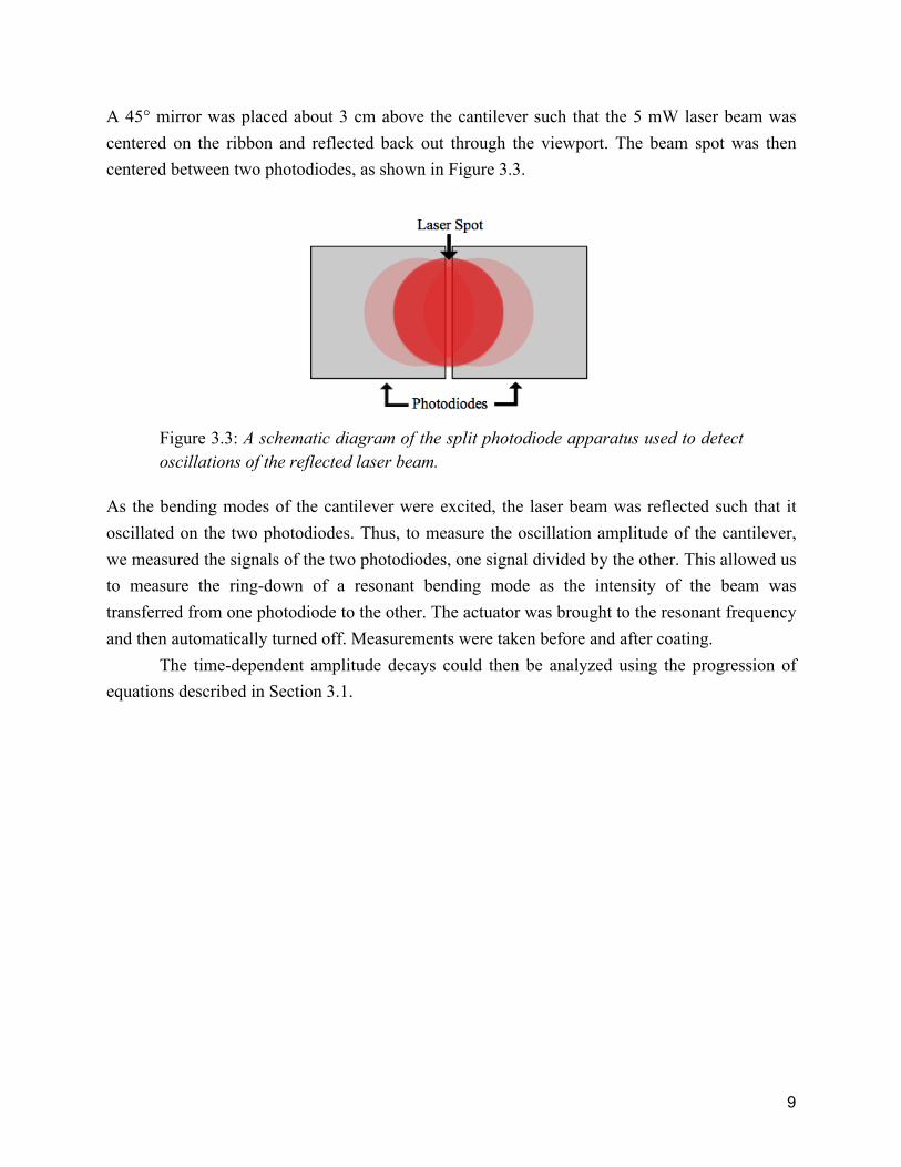
A 45° mirror was placed about 3 cm above the cantilever such that the 5 mW laser beam was centered on the ribbon and reflected back out through the viewport. The beam spot was then centered between two photodiodes, as shown in Figure 3.3.
Figure 3.3: A schematic diagram of the split photodiode apparatus used to detect oscillations of the reflected laser beam.
As the bending modes of the cantilever were excited, the laser beam was reflected such that it oscillated on the two photodiodes. Thus, to measure the oscillation amplitude of the cantilever, we measured the signals of the two photodiodes, one signal divided by the other. This allowed us to measure the ring-down of a resonant bending mode as the intensity of the beam was transferred from one photodiode to the other. The actuator was brought to the resonant frequency and then automatically turned off. Measurements were taken before and after coating. The time-dependent amplitude decays could then be analyzed using the progression of equations described in Section 3.1.
10
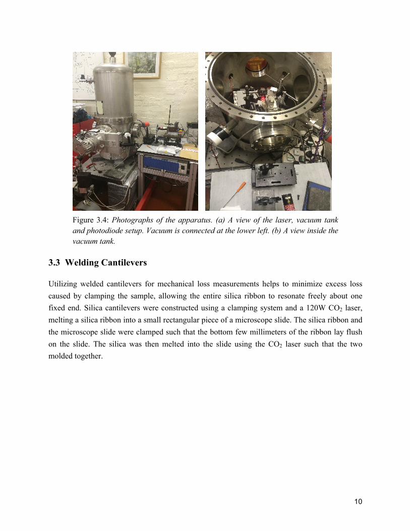
Figure 3.4: Photographs of the apparatus. (a) A view of the laser, vacuum tank and photodiode setup. Vacuum is connected at the lower left. (b) A view inside the vacuum tank.
3.3 Welding Cantilevers Utilizing welded cantilevers for mechanical loss measurements helps to minimize excess loss caused by clamping the sample, allowing the entire silica ribbon to resonate freely about one fixed end. Silica cantilevers were constructed using a clamping system and a 120W CO2 laser, melting a silica ribbon into a small rectangular piece of a microscope slide. The silica ribbon and the microscope slide were clamped such that the bottom few millimeters of the ribbon lay flush on the slide. The silica was then melted into the slide using the CO2 laser such that the two molded together.

11
Figure 3.5: On the left is a photograph of a cantilever being welded and on the right, a schematic diagram of the welding apparatus - not to scale.
3.4 Gas Damping All cantilever mechanical loss measurements are highly sensitive, thus we must attempt to account for and minimize excess noise. Although measurements are taken near vacuum, collisions with air molecules causes dampened cantilever oscillations. This loss due to gas damping, 𝜙!"#, is approximately described by
𝜙!"# ≈𝐴𝑃𝑚𝜔
𝑀𝑅𝑇 ,
where A is surface area, P is pressure in the tank, m is the mass of the cantilever, ω is angular frequency of the cantilever at a resonant mode, M is the mass of one mole of the gas, R is the gas constant, and T is temperature. Due to the inverse proportionality of loss in response to angular frequency, the maximum loss is expected at the lowest resonant mode, approximately 80 Hz. To ensure that our experiment produces accurate mechanical loss measurements, we put the sample under vacuum pressure on the order of 1 × 10⁻⁶ mbar, a full three orders of magnitude less than our empirically required value. Thus, all damping caused by gas collisions is considered negligible in our measurements.
(6)
12
3.5 Analyzing Mechanical Loss - Actual, Realistic and Zero The calculation of a coating’s mechanical loss is dependent both on the loss measurements before and after coating as seen in
𝜙!"#$%&(𝜔∘)=𝜙!"#!$%&$'(𝜔∘)+!!!!𝜙!"#$%&'(𝜔∘).
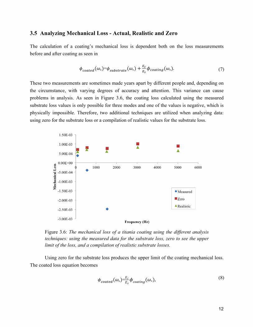
These two measurements are sometimes made years apart by different people and, depending on the circumstance, with varying degrees of accuracy and attention. This variance can cause problems in analysis. As seen in Figure 3.6, the coating loss calculated using the measured substrate loss values is only possible for three modes and one of the values is negative, which is physically impossible. Therefore, two additional techniques are utilized when analyzing data: using zero for the substrate loss or a compilation of realistic values for the substrate loss.
Figure 3.6: The mechanical loss of a titania coating using the different analysis techniques: using the measured data for the substrate loss, zero to see the upper limit of the loss, and a compilation of realistic substrate losses.
Using zero for the substrate loss produces the upper limit of the coating mechanical loss. The coated loss equation becomes
𝜙!"#$%&(𝜔∘)=𝐸𝑐𝐸𝑠𝜙𝑐𝑜𝑎𝑡𝑖𝑛𝑔(𝜔∘),
(7)
(8)
13
where the total loss of the coated cantilever is proportional to the coating loss by the energy ratio. To achieve a more complete understanding of the coating, another method is used. All of the silica cantilevers in this paper were produced from the same batch of silica and welded by the same person. Therefore, the error in our most recent results can tentatively be attributed to the measurements of the uncoated cantilevers. Over twenty substrate measurements were taken of this batch of cantilevers and were compiled to render realistic values for the loss of the first six bending modes. These values were easily extracted because of concentrated clumping in the mechanical loss data. This method extracted the substrate loss outliers that produced negative coating losses. The coated loss equation then becomes
𝜙!"#$%&(𝜔∘)=𝜙!"#$%&'%((𝜔∘)+!!!!𝜙!"#$%&'(𝜔∘),
where the coating losses became physically possible and more consistent.
4 Titania Doped Tantala Coatings The LIGO gravitational wave detector currently utilizes a multi-layer coating composed of 25% TiO2/75% Ta2O5 high index layers and amorphous SiO2 low index layers. Silica and tantala are used for their optical properties. The thermal loss of the silica layer greatly decreases when it is heat treated to 900°C. But, at just over 600°C, tantala begins to crystallize which can cause the coating to crack and buckle. Doping tantala with titania increases the crystallization point while maintaining the desired optical properties of tantala, allowing for higher temperature heat treatments. By further doping tantala with 50% or 75% titania, the crystallization point will become even higher. Here, we examine the mechanical loss of titania doped tantala coatings at room temperature before heat treatment.
(9)

14
Figure 4.1: The mechanical loss of various tantala and titania composites assuming the substrate loss is realistic.
Figure 4.1 depicts the mechanical loss of four different tantala/titania coatings on silica cantilevers for the first six bending modes. Mode 2 of the 75% titania was disregarded because a negative coating loss is nonphysical. The pure tantala coating has the highest mechanical loss and the 50% titania doped tantala coating has the lowest. To fill the gap in our data around 25% titania doped tantala, where the composite in the LIGO multi-layer would be, data from Bassiri [11] and Harry [10] were inserted. Bassiri and Harry used titania doped tantala coatings on silica cantilevers as well, but the measurements were taken after heat treatments at 600℃ for 24 hours.
Figure 4.2: The mechanical loss of tantala coatings dependent upon the percent titania doping and comparing current and previous results. All cantilevers
15
measured by Bassiri and Harry were heat treated for 24 hours at 600℃. Measurements assume the substrate loss is realistic.
Doping tantala with titania relieves some of the internal friction and lowers the mechanical loss in the coating. The opposite is also true. Doping titania with tantala relieves some of the internal friction, lowering the mechanical loss of a purely titania coating. Bassiri found this trend as well, finding the minimum mechanical loss at 25.7% titania doped tantala. In our findings, even including previously acknowledged results, the minimum mechanical loss is found at 52% titania doped tantala. Further examination of both chemical structure and mechanical loss are necessary to solidify this trend.
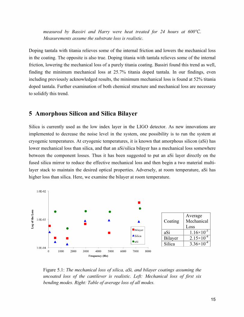
5 Amorphous Silicon and Silica Bilayer Silica is currently used as the low index layer in the LIGO detector. As new innovations are implemented to decrease the noise level in the system, one possibility is to run the system at cryogenic temperatures. At cryogenic temperatures, it is known that amorphous silicon (aSi) has lower mechanical loss than silica, and that an aSi/silica bilayer has a mechanical loss somewhere between the component losses. Thus it has been suggested to put an aSi layer directly on the fused silica mirror to reduce the effective mechanical loss and then begin a two material multi-layer stack to maintain the desired optical properties. Adversely, at room temperature, aSi has higher loss than silica. Here, we examine the bilayer at room temperature.
Figure 5.1: The mechanical loss of silica, aSi, and bilayer coatings assuming the uncoated loss of the cantilever is realistic. Left: Mechanical loss of first six bending modes. Right: Table of average loss of all modes.
Coating Average Mechanical Loss
aSi 1.16×10⁻³ Bilayer 2.15×10⁻⁴ Silica 3.36×10⁻⁴
16
The bilayer consists of a 112 nm aSi layer and a 267 nm silica layer. As expected, the loss of the silica is lower than the aSi. In alignment with cryogenic measurements, the loss due to the bilayer resides between the loss of the components. This implies that aSi and silica bilayers create a new coating with a composite mechanical loss.
6 Deposition Methods There are many coating technologies, each with distinct strengths and weaknesses. Here, we will compare ion-plating and ion-beam sputtering. Then, we will further analyze the effect of high versus low energy DC magnetron sputtering. The three technologies are described as follows. Ion-plating, more formally known as Reactive Low Voltage Ion-Plating, is a coating technology utilizing a plasma source. Between the plasma source and the coating material, a low-voltage electrical arc of an electron beam is formed, allowing the coating material to efficiently ionize. Due to the potential difference between at the unionized crucible holding the coating material and the insulated substrate holder, the coating ions hit the substrate with high kinetic energy and pack to maximum density. [15] Ion-beam sputtering uses source ions to generate a coating ion beam focused on the substrate. The source ions are accelerated toward the coating material by an electric field. This causes the coating material to ionize and accelerate toward the substrate. These ions are highly energetic and therefore create coatings with excellent adhesion and high packing density. DC magnetron sputtering is another coating technology. The coating material is bombarded by ionized gas molecules, causing the coating atoms to be displaced, hit the substrate, and bond at the atomic level. Several high-voltage DC magnetron cathodes are placed behind the substrate to steer the coating atoms toward the substrate for accurate and quality coatings. The substrate is continuously rotated on a drum, periodically passing an oxygen plasma to efficiently oxidize the coating. 6.1 Ion-Plating and Ion-Sputtering Ion-sputtering has been used for precision coating for years. It provides relatively thin, consistent coatings, essential for gravitational wave detectors. But as the noise level in gravitational wave detectors is forced to lessen, other techniques need to be created and investigated. One of the emerging possibilities is ion-plating. To compare ion-plating and ion-sputtering, we analyzed aSi coatings deposited by each respective technology.
17
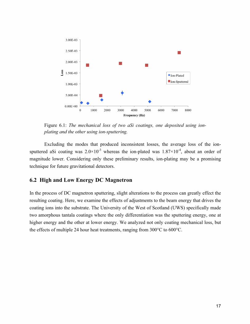
Figure 6.1: The mechanical loss of two aSi coatings, one deposited using ion-plating and the other using ion-sputtering.
Excluding the modes that produced inconsistent losses, the average loss of the ion-sputtered aSi coating was 2.0×10⁻³ whereas the ion-plated was 1.87×10⁻⁴, about an order of magnitude lower. Considering only these preliminary results, ion-plating may be a promising technique for future gravitational detectors.
6.2 High and Low Energy DC Magnetron In the process of DC magnetron sputtering, slight alterations to the process can greatly effect the resulting coating. Here, we examine the effects of adjustments to the beam energy that drives the coating ions into the substrate. The University of the West of Scotland (UWS) specifically made two amorphous tantala coatings where the only differentiation was the sputtering energy, one at higher energy and the other at lower energy. We analyzed not only coating mechanical loss, but the effects of multiple 24 hour heat treatments, ranging from 300°C to 600°C.

18
Figure 6.2: The average mechanical loss of DC magnetron sputtered tantala coatings. Deposited at differing energies.
As depicted in Figure 6.2, the mechanical loss of the high energy sputtered coating is within error of the low energy coating. Further research must be done on the mechanical loss of coatings deposited at differing energies. Alternatively, heat treatments of the two coatings resulted in two distinct trends. Both coatings decreased in mechanical loss when initially heat treated, but the high energy coating continued to decrease in mechanical loss until it hit its minimum mechanical loss after being heat treated to 450°C. The low energy coating reached its minimum mechanical at a temperature less than 400°C. This may imply that the low energy coating begins to crystallize under less heat than the high energy coating. Further structural examination and mechanical loss measurements of these two coating techniques are necessary for definitive answers.
7 Alumina Coatings The thickness of a coating should not affect the calculated coating mechanical loss. This is due to the energy ratio. The energy ratio compares the energy stored in the coating material to the energy stored in the substrate, allowing us to examine the mechanical loss due to the coating material, regardless of thickness. Here, we compare two alumina coatings, one that is 2 µm thick and another at 0.5 µm.

19
Figure 7.1: The mechanical loss of as-deposited alumina coatings of different thicknesses. Coating applied using ion-beam sputtering by ATF.
It is evident in Figure 7.1 that regardless of the thickness of an alumina coating, the calculated mechanical loss is the same. The average loss of this alumina coating deposited by Advanced Thin Films (ATF) is 5.5×10⁻⁴. Previously accepted alumina loss values are 3.11×10⁻⁴ and 1.61×10⁻⁴ deposited by MLD Technologies LLC (MLD) and Wave Precision (WP) respectively [9]. All of these coatings were measured as deposited.
8 Conclusion The mechanical loss measurements in this paper suggest that doping tantala with titania reduces the mechanical loss of the coating, with a minimum loss somewhere between a 25.7% and 52% doping. Additionally, a two material multi-layer consisting of aSi and silica results in a composite mechanical loss, both at cryogenic temperatures and at room temperature. Furthermore, the thickness of a coating does not effect the coating mechanical loss, as proved when we analyzed alumina. All results in this paper confirm that the method of deposition significantly effects the resulting mechanical loss of the coating. Ion-plated aSi coatings provided significantly lower loss in comparison to ion-beam sputtered aSi coatings by an order of magnitude. Also, the energy of the ion-beam in DC magnetron sputtering has structural effects on the resulting coatings causing them to respond to heat treatment differently. The low energy DC magnetron tantala coating had
20
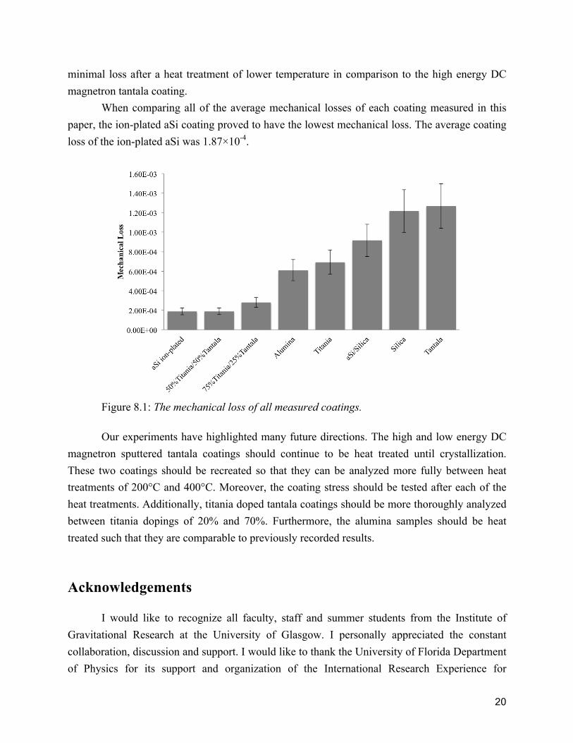
minimal loss after a heat treatment of lower temperature in comparison to the high energy DC magnetron tantala coating. When comparing all of the average mechanical losses of each coating measured in this paper, the ion-plated aSi coating proved to have the lowest mechanical loss. The average coating loss of the ion-plated aSi was 1.87×10⁻⁴.
Figure 8.1: The mechanical loss of all measured coatings.
Our experiments have highlighted many future directions. The high and low energy DC magnetron sputtered tantala coatings should continue to be heat treated until crystallization. These two coatings should be recreated so that they can be analyzed more fully between heat treatments of 200°C and 400°C. Moreover, the coating stress should be tested after each of the heat treatments. Additionally, titania doped tantala coatings should be more thoroughly analyzed between titania dopings of 20% and 70%. Furthermore, the alumina samples should be heat treated such that they are comparable to previously recorded results.
Acknowledgements I would like to recognize all faculty, staff and summer students from the Institute of Gravitational Research at the University of Glasgow. I personally appreciated the constant collaboration, discussion and support. I would like to thank the University of Florida Department of Physics for its support and organization of the International Research Experience for
21
Undergraduates (IREU) program, especially Guido Mueller, Kristin Nichola, and Bernard Whiting. I am grateful for the financial support of the NSF in the USA and the University of Glasgow in the UK.
References [1] J. Hough, S. Rowan, The Search for Gravitational Waves, Einstein: Gravitational Waves, 2005. [2] I. Martin, S. Reid, Optical Coatings and Thermal Noise in Precision Measurement, Cambridge University Press, Cambridge, UK, 2012. [3] P. G. Murray, I. W. Martin, M. R. Abernathy, K. Craig, J. Hough, T. Pershing, S. Penn, R. Robie, S. Rowan, Ion-beam Sputtered Amorphous Silicon Films for Cryogenic Gravitational Wave Detectors, University of Glasgow, 2015. [4] J. Steinlechner, I. W. Martin, A. Bell, G. Cole, J. Hough, S. Penn, S. Rowan, S. Steinlechner, Mapping the Optical Absorption of a Substrate-Transferred Crystalline AlGaAs Coating at 1.5µm, Class. Quantum Grav. 32 (2015) 105008 (12pp). [5] S. Reid, G. Cagnoli, D. R. M. Crooks, J. Hough, R. Route, P. Murray, S. Zappe, S. Rowan, M. M. Fejer, Mechanical Dissipation in Silicon Flexures, Physics Letters A 351 (2006) 205-211. [6] M. Pitkin, S. Reid, S. Rowan, J. Hough, Gravitational Wave Detection by Interferometry (Ground and Space), Living Rev. Relativity, 14 (2011), 5. [7] I. W. Martin, PhD Thesis, University of Glasgow, 2009. [8] R. Robie, Second Year Report, University of Glasgow, 2015. [9] D. R. M. Crooks, G. Cagnoli, M. M. Fejer, G. Harry, J. Hough, B. T. Khuri-Yakub, S. Penn, R. Route, S. Rowan, P. H. Sneddon, I. O. Wygant, G. G. Yaralioglu, Experimental measurements of mechanical dissipation associated with dielectric coatings formed using SiO2, Ta2O5, and Al2O3, Class. Quantum Grav. 23 (2006) 4953-4965. [10] G. M. Harry, et al. Titania-doped tantala/silica coatings for gravitational-wave detection, Class. Quantum Grav. 24 (2007) 405-415. [11] R. Bassiri, et al. Correlations between the mechanical loss and atomic structure of amorphous TiO2-doped Ta2O5 coatings, Acta Materialia 61 (2013) 1070-1077. [12] K. Craig, PhD Thesis, University of Glasgow, 2015. [13] S. Barta, Effective Young’s modulus and Poisson’s ratio for the particular composite, Journal of Applied Physics, 75(7):3258-3263, Apr 1994. [14] LIGO Caltech, Catching the Gravitational Wave, labcit.ligo.caltech.edu/LIGO_web/about/brochure, October 4, 2001. [15] Tafelmaier, Ion-Plating, www.tafelmaier.de.