mechanical power press - ohiobwc · pdf filesafety hazard alerts and talks, training, ... the...
TRANSCRIPT

Mechanical Power Press
BWC Division of Safety and Hygiene Training Center


TABLE OF CONTENTS
SECTION CONTENTS 1 Definitions 2 Power Press Mechanics 3 Standards and Interpretations 4 ANSI Standard 5 Training 5 – A Full Revolution Section One 5 – B Part Revolution Section Two 5 – C Part & Full Revolution Section Three 5 – D Part & Full Revolution Section Four 5 – E Part & Full Revolution Section Five 5 – F Full Revolution Section Six 5 – G Full Revolution Section Seven 5 – H Part Revolution Section Eight 5 – I Part Revolution Section Nine 5 – J Part & Full Section Ten 5 – K Part Revolution Section Eleven 5 – L Part Revolution Section Twelve 6 Ergonomics for Power Presses 7 Industrial Hygiene for Power Presses 8 Lockout/Tagout Standard
• Letters of Interpretation • Sample Program • OSHA Standards
9. Die Setting
August 2008 Printed within BWC

-
TABLE OF CONTENTS – Continued
10. Inspections 11. Personal Protective Equipment 12. Miscellaneous
ii

Mechanical Power Press
Course Objectives
At the end of the course, participants will understand:• safe operation of full-revolution and part-revolution presses• point-of-operation guarding• brake monitoring• control reliability• die setting• electrical systems• inspection, maintenance and training requirements• safety codes and standards (OSHA State of Ohio and ANSI)• industrial hygiene and ergonomics as they pertain to power presses
iii

Mechanical Power Press
Follow up activites:
• Identified improperly guarded machines in our facility.
• Utilized the checklist from the manual to evaluate our current machine guarding status.
• Establish an effective written training outline for employees/new operators.
• Establish a written die setting procedure.
iv

Activity P
lan
Activity
Oth
er
people
involv
ed
Targ
etD
eadlin
e� � � � � � � �
v

Resources Available from the Division of Safety & Hygiene (DSH) Libraries(800) 644-6292 (614) 466-7388
Safety training:
• Safety talks, outlines and scripts - DSH Safety leader’s discussion guide, Training
Center’s One-hour safety presentations, reference books, web resources
• Videos – hundreds of safety and health topics
• Books and articles on training techniques
Machine and equipment safety:
• Safety standards (ANSI, NFPA, CGA)
• Books and articles on power presses, material handling equipment, lockout/tagout, etc.
Sample written programs:
• DSH program profiles and sample written programs
• Reference books
• Internet resources
Illness and injury statistics:
• Statistics from the U.S. Bureau of Labor Statistics
• National Safety Council’s Injury Facts
• National Institute of Occupational Safety & Health (NIOSH) studies
Hazard communication and chemical safety:
• Chemical safety information
• Material safety data sheets (MSDSs)
• Sample written programs
• Videos
• Internet resources
Safety standards
• American National Standards Institute (ANSI) standards (including standards for construction, machinery and equipment, personal protective equipment)
• National Fire Protection Association (NFPA) fire codes (including the Life Safety Code and the National Electrical Code)
• Compressed Gas Association (CGA) standards
Other topics of interest (books, articles, magazines, videos and standards):
• Confined spaces
• Electrical safety
• Job safety analysis
• New employee orientation
• Powered industrial trucks
• Respiratory protection
• Scaffolds
• Spill response
Directories and lists of vendors of safety equipment
Occupational Safety & Health Administration (OSHA) regulations
Manual of Uniform Traffic Control Devices (MUTCD)
Recommendations of useful Internet sites
BWC publications
vi

Saving You Time and Research Requests for copies of OSHA standards, information on starting a safety committee, a video on accident investigation techniques -- these are some of the thousands of inquiries BWC’s Division of Safety & Hygiene (DSH) libraries receive each year. DSH has two libraries to serve you:
• The central library in the William Green Building in downtown Columbus; • The resource center and video library located at the Ohio Center for Occupational Safety and
Health (OCOSH) in Pickerington. Both libraries are open 8 a.m. to 4:45 p.m., Monday through Friday. Your need for information does not require a visit to the library. You can phone, fax, or e-mail your requests and receive a quick response. The central library provides free information services on the topics of occupational safety and health, workers’ compensation and rehabilitation. The OCOSH resource center provides similar services for those who visit OCOSH for meetings and training center classes. The video library offers an extensive collection of videotapes to supplement your organization’s safety and health training program. It is a convenient and popular source for Ohio employers to borrow quality occupational safety- and health-related training aids. Visit our Web site at www.ohiobwc.com. Central Library 30 W. Spring St., Third Floor Columbus OH 43215-2256 1-800-OHIOBWC (614) 466-7388 (614) 644-9634 (fax) [email protected] OCOSH Resource Center 13430 Yarmouth Drive Pickerington OH 43147 1-800-OHIOBWC Resource center (614) 728-6464 Video library (614) 644-0018
vii

INTERNET WEB SITES for
OCCUPATIONAL SAFETY & HEALTH INFORMATION May 2008
The Ohio Bureau of Workers’ Compensation provides a variety of safety tools and resources on our web site, www.ohiobwc.com. Click on Safety Services to find out more about what BWC’s Division of Safety & Hygiene offers online. Tools and resources include lifting guidelines, recordkeeping spreadsheets, sample OSHA program guides, and training materials. You’ll also find a longer version of this list of web sites. GENERAL CANADIAN CENTRE FOR OCCUPATIONAL HEALTH & SAFETY (CCOHS) http://ccohs.ca This Canadian government site has an extensive Internet directory. There is also a unique feature called “OSH Answers” and a guide to safety-related acronyms. NATIONAL SAFETY COUNCIL http://www.nsc.org Visit this web site for information on safety in the workplace, at home, on the road and in the community. NYCOSH http://www.nycosh.org The New York Committee for Occupational Safety & Health offers news releases, links to helpful safety resources, strategies for safer workplaces, information on workplace hazards, workers’ compensation and much more. OCCUPATIONAL HAZARDS http://www.occupationalhazards.com The online version of the magazine Occupational Hazards is filled with today’s headlines, articles, white papers, case studies, and product news. OKLAHOMA STATE UNIVERSITY http://www.pp.okstate.edu/ehs The Department of Environmental Health & Safety at OSU has an online safety resource library with topics from A-Z. Go to the "Links Library" option. OREGON HEALTH & SCIENCE UNIVERSITY http://www.croetweb.com This site consists of information on occupations & industries, chemical hazards, workplace safety issues, ergonomic issues, biological hazards, and includes materials in Spanish.

2 VERMONT SIRI http://hazard.com Contains a wide variety of resources: MSDSs, an online library of graphics, articles and PowerPoint presentations, e-mail discussion list archives, and a list of safety & health consultants. FEDERAL GOVERNMENT AGENCY FOR TOXIC SUBSTANCES AND DISEASE REGISTRY http://www.atsdr.cdc.gov Look for information on hazardous substances, emergency response and hazardous waste sites. BUREAU OF LABOR STATISTICS, SAFETY & HEALTH http://www.bls.gov/bls/safety.htm Find national statistics on work-related injuries and illnesses and fatalities. CENTERS FOR DISEASE CONTROL & PREVENTION (CDC) http://www.cdc.gov A good resource for general public health issues throughout the United States. Health topics from A-Z give an in-depth look at most communicable diseases as well as topics such as safe driving, violence, and air pollution. ENVIRONMENTAL PROTECTION AGENCY (EPA) http://www.epa.gov The EPA’s web site provides a wealth of information on a wide range of topics. Of particular interest: resources on lead, asbestos, indoor air quality, mold, and school environmental issues. FEDERAL EMERGENCY MANAGEMENT AGENCY (FEMA) http://www.fema.gov For information on disasters and emergencies nationwide, access this web site. Publications include options for emergency preparedness and prevention, response and recovery, disaster fact sheets, and public awareness information. MINE SAFETY AND HEALTH ADMINISTRATION (MSHA) http://www.msha.gov Features information on mine safety and health, including noise, dust, statistics, safety hazard alerts and talks, training, regulations, and rescue. NATIONAL INSTITUTE FOR OCCUPATIONAL SAFETY & HEALTH (NIOSH) http://www.cdc.gov/niosh NIOSH’s site describes their services and research activities and provides information on many workplace safety and health topics. Most of their publications are available online.

3 NATIONAL LIBRARY OF MEDICINE (NLM) http://www.nlm.nih.gov The world’s largest medical library: a reliable source for medical, health and chemical hazard information. OCCUPATIONAL SAFETY & HEALTH ADMINISTRATION (OSHA) http://www.osha.gov OSHA’S web site includes compliance assistance resources, online publications, statistics, OSHA standards & directives, and a very useful A-Z site index. OHIO OHIO DEPT. OF HEALTH http://www.odh.state.oh.us Provides a wide variety of public health information, including occupational and environmental health, women's health, and health resources. OHIO EPA http://www.epa.state.oh.us Use the “Topic Index” to find Ohio EPA regulations and information on permits, hazardous waste, pollution prevention, wastewater, wetlands, and much more. STATE LIBRARY OF OHIO/OHIOLINK http://slonet.state.oh.us Search the State Library of Ohio’s online catalog which includes BWC’s Division of Safety & Hygiene library books. SPECIFIC (BY SUBJECT) CONSTRUCTION http://www.cdc.gov/elcosh eLCOSH is a comprehensive library of construction safety information presented in both English and Spanish with items searchable by trade, hazard, job site, etc. DRUG-FREE WORKPLACE http://www.dol.gov/workingpartners Working Partners for an Alcohol- and Drug-Free Workplace. Provides guidelines on establishing a workplace substance abuse program. Search the Substance Abuse Information Database. From the U.S. Dept. of Labor. EMERGENCY MANAGEMENT GUIDE FOR BUSINESS & INDUSTRY http://www.fema.gov/business/guide Presents a step-by-step approach to emergency planning, response, and recovery for companies of all sizes. From the Federal Emergency Management Agency.

4 ERGONOMICS http://www.ergoweb.com Ergoweb’s site offers ergonomics news, a buyer’s guide and case studies, in addition to sources for software and services. FIRE CODES http://www.nfpa.org The National Fire Protection Association (NFPA) codes can be viewed full-text online. HAZARDOUS MATERIALS AND HAZARDOUS WASTE http://tools.niehs.nih.gov/wetp The National Clearinghouse for Worker Safety and Health Training is a resource for workers and trainers who are involved in the handling of hazardous waste or in responding to emergency releases of hazardous materials and terrorist actions. INDOOR AIR QUALITY http://sis.nlm.nih.gov/enviro/indoorairpollution.html Compiled by the National Library of Medicine, this web page provides information on a variety of indoor air topics as well as glossaries, database searches and web pages in Spanish. MSDS http://www.ilpi.com/msds Touted as “Where to find material safety data sheets on the Internet”, this site offers links to 100 free sites as well as news, FAQs, and an MSDS glossary. SAFETY MANUALS & SAMPLE WRITTEN PROGRAMS ILLINOIS ONSITE SAFETY & HEALTH CONSULTATION PROGRAM http://www2.illinoisbiz.biz/osha/resource.htm At this site you will find sample written programs on a variety of topics. Also available are checklists and safety guide books, some in Spanish. OSHA http://www.osha.gov/dcsp/compliance_assistance/sampleprograms.html OSHA provides sample written programs for employers to use as guidance when developing their own customized programs tailored to their specific workplaces.
Ohio Bureau of Workers’ Compensation, Div. of Safety & Hygiene Libraries (800) 644-6292
(614) 466-7388 (614) 644-9634 (fax) E-Mail: [email protected]
www.ohiobwc.com

Definitions

Adjustable barrier guard means a barrier requiring adjustment for each job or die setup. Antirepeat means the part of the clutch/brake controls system designed to limit the press to a single stroke if the tripping means is held operated. Antirepeat requires release of all tripping mechanisms before another stroke can be initiated. Antirepeat is also called single stroke reset or reset circuit. Automatic feeding means feeding wherein the material or part being processed is placed within or removed from the point of operation by a method or means not requiring action by an operator on each stroke of the press. Bolster plate means the plate attached to the top of the bed of the press having drilled holes or T-slots for attaching the lower die or die shoe. Brake means the mechanism used on a mechanical power press to stop and/or hold the crankshaft, either directly or through a gear train, when the clutch is disengaged. Brake monitor means a sensor designed, constructed, and arranged to monitor the effectiveness of the press braking system. Clutch means the coupling mechanism used on a mechanical power press to couple the flywheel to the crankshaft, either directly or through a gear train. Concurrent means acting in conjunction, and is used to describe a situation wherein two or more controls exist in an operated condition at the same time. Continuous means uninterrupted multiple strokes of the slide without intervening stops (or other clutch control action) at the end of individual strokes. Control System means sensors, manual input and mode selection elements, interlocking and decision-making circuitry, and output elements to press operating mechanism. Counterbalance means the mechanism that is used to balance or support the weight of the connecting rods, slide, and slide attachments. Device means a press control or attachment that: (i) Restrains the operator from inadvertently reaching into the point of operation; on (ii) Prevents normal press operation if the operator's hands are inadvertent ly within the point of operation; or (iii) Automatically withdraws the operator's hands, if the operator's hands are inadvertently within the point of operation as the dies close. Die means the tooling used in a press for cutting or forming material. An upper and lower die make a complete set. Die builder means any person who builds dies for power presses. Die enclosure guard means an enclosure attached to the die shoe or stripper, or both, in a fixed position. Die set means a tool holder held in alignment by guide posts and bushings and consisting of a lower shoe, an upper shoe or punch holder, and guide posts and bushings. Die setter means an individual who places or removes dies in or from mechanical power presses, and who, as a part of his duties, makes the necessary adjustments to cause the
Section 1 - 1

tooling to function properly and safely. Die setting means the process of placing or removing dies in or from a mechanical power press, and the process of adjusting the dies, other tooling and safeguarding means to cause them to function properly and safely. Die shoe means a plate or block upon which a die holder is mounted. A die shoe functions primarily as a base for the complete die assembly, and, when used, is bolted or clamped to the bolster plate or the face of slide. Direct drive means the type driving arrangement wherein no clutch is used; coupling and decoupling of the driving torque is accomplished by energizing and deenergization of a motor. Even though not employing a clutch, direct drives match the operational characteristics of "part revolution clutches" because the driving power may be disengaged during the stroke of the press. Ejector means a mechanism for removing work or material from between the dies. Face of slide means the bottom surface of the slide to which the punch or upper die is generally attached. Feeding means the process of placing or removing material within or from the point of operation. Fixed barrier guard means a die space barrier attached to the press frame. Foot control means the foot operated control mechanism designed to be used with a clutch or clutch/brake control system. Foot pedal means the foot operated lever designed to operate the mechanical linkage that trips a full revolution clutch. Full revolution clutch means a type of clutch that, when tripped, can not be disengaged until the crankshaft has completed a full revolution and the press slide a full stroke. Gate or movable barrier device means a movable barrier arranged to enclose the point of operation before the press stroke can be started. Guard means a barrier that prevents entry of the operator's hands or fingers into the point of operation. Guide post means the pin attached to the upper or lower die shoe, operating within the bushing on the opposing die shoe, to maintain the Hand feeding tool means any hand-held tool designed for placing or removing material or parts to be processed within or from the point of operation. Holdout or restraint device means a mechanism, including attachments for the operator's hands, that when anchored and adjusted prevent the operator's hands from entering the point of operation. Inch means an intermittent motion imparted to the slide (on machined using part revolution clutches) by momentary operation of the "inch" operating means. Operation of the "inch" operating means engages the driving clutch so that a small portion of one stroke or indefinite stroking can occur, depending on the length of time the "inch" operating means is held operated. "Inch" is a function used by the die setter for setup of
Section 1 - 2

dies and tooling, but is not intended for use during production operations by the operator. Interlocked press barrier guard means a barrier attached to the press frame and interlocked so that the press stroke can not be started normally unless the guard itself, or its hinged or movable section, enclose the point of operation. Jog means an intermittent motion imparted to the slide by momentary operation of the drive motor, after the clutch is engaged with the flywheel at rest. Knockout means a mechanism for releasing material from either die. Liftout means the mechanism also known as knockout. Manual feeding means feeding wherein the material or part being processed is handled by the operator on each stroke of the press. Operator's station means the complete complement of controls used by or available to an operator on a given operation for stroking the press. Part revolution clutch means a type of clutch that can be disengaged at any point before the crankshaft has completed a full revolution and the press slide a full stroke. Pinch point means any point other than the point of operation at which it is possible for a part of the body to be caught between the moving parts of a press or auxiliary equipment, or between moving and stationary parts of a press or auxiliary equipment or between the material and moving part or parts of the press or auxiliary equipment. Point of operation means the area of the press where material is actually positioned and work is being performed during any process such as shearing, punching, forming, or assembling. Presence sensing device means a device designed, constructed and arranged to create a sensing field or area and to deactivate the clutch control of the press when an operator's hand or any other part of his body is within such field or area. Press means a mechanically powered machine that shears, punches, forms or assembles metal or other material by means of cutting, shaping, or combination dies attached to slides. A press consists of a stationary bed or anvil, and a slide (or slides) having a controlled reciprocating motion toward and away from the bed surface, the slide being guided in a definite path by the frame of the press. Pullout device means a mechanism attached to the operator's hands and connected to the upper die or slide of the press, that is designed, when properly adjusted, to withdraw the operator's hand as the dies close, if the operator's hands are inadvertently within the point of operation. Repeat means an unintended or unexpected successive stroke of the press resulting from a malfunction. Safety block means a prop that, when inserted between the upper and lower dies or between the bolster plate and the face of the slide, prevents the slide from falling of its own deadweight. Semiautomatic feeding means feeding wherein the material or part being processed is placed within or removed from the point of operation by an auxiliary means controlled by the operator on each stroke of the press.
Section 1 - 3

Single stroke means one complete stroke of the slide, usually initiated form a full open (or up) position, followed by closing (or down), and then a return to the full open position. Single stroke mechanism means an arrangement used on a full revolution clutch to limit the travel of the slide to one complete stroke at each engagement of the clutch. Slide means the main reciprocating press member. A slide is also called a ram, plunger, or platen. Stop control means an operator control designed to immediately deactivate the clutch control and activate the brake to stop slide motion. Stripper means a mechanism or die part for removing the parts or material from the punch. Stroking selector means the part of the clutch/brake control that determines the type of stroking when the operating means is actuated. The stroking selector generally includes positions for "Off" (Clutch Control), "Inch," "Single Stroke," and "Continuous" (when Continuous is furnished). Sweep device means a single or double arm (rod) attached to the upper die or slide of the press and designed to move the operator's hands to a safe position as the dies close, if the operator's hands are inadvertently within the point of operation. Trip or (tripping) means activation of the clutch to "run" the press. Turnover bar means a bar used in die setting to manually turn the crankshaft of the press. Two-hand trip means a clutch actuating means requiring the concurrent use of both hands of the operator to trip the press. Two-hand control device means a two-hand trip that further requires concurrent pressure from both hands of the operator during a substantial part of the die-closing portion of the stroke of the press. Unitized tooling means a type of die in which the upper and lower members are incorporated into self-contained units arranged as to hold the die members in alignment.
Section 1 - 4

Power Press M
echanics


Section 2 - 1
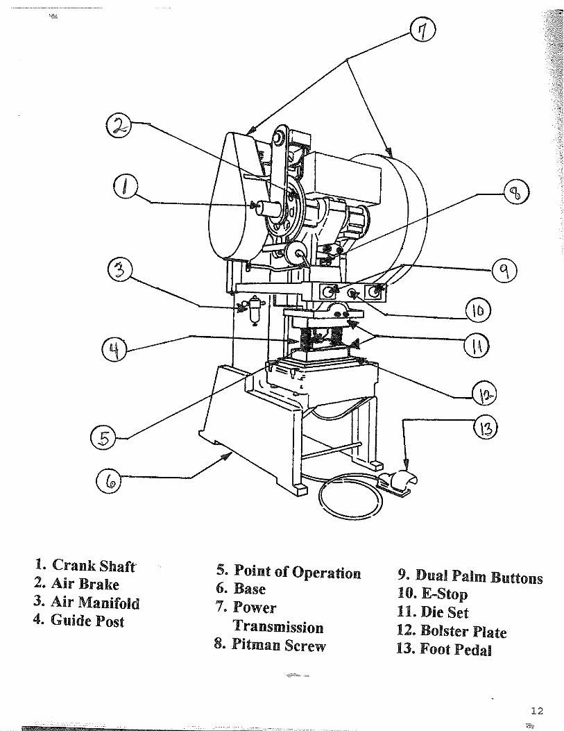
Safeguarding Mechanical Power Press Operators
Figures 1 and 2 show the major types of power presses used in the metalworkingindustry.5 These presses develop from several hundred pounds to several thousand tons ofpressure to form metal, and require one to several workers to operate the press. Themethods, techniques, and safety devices for safeguarding the point of operation weredeveloped from 1914 (American Machinist)8 to current practices (National SafetyCouncil, 1979), and include barrier guards, pull-out devices, two-hand controls, andpresence sensing devices.
With reference to Figure 1 and 2, a full revolution press is designed with a type ofclutch that, when tripped, cannot be disengaged until the crankshaft has completed a fullrevolution, and the press slide, a full stroke. A partial revolution press is designed with atype of clutch that can be disengaged at any point before the crankshaft has completed afull revolution, and the press slide, a full stroke. Thus, providing adequate methods ofoperator safeguarding depends not only on the point of operation but also on the modesof press operation.
Safety Standards for presses were first published in 1926 (U.S. Department ofLabor) 7 and revised periodically to the current Standard (ANSI B11.1-1971).Essentially, the Standard follows safeguarding criteria based on research conducted in1949 (American Mutual Insurance Alliance, 1966), 9 as shown in figure 3. These criteriaprovide design guidelines to prevent entry of hands or fingers into the point of operation.
It has long been recognized that barrier guards, pull-out devices, and two-handcontrols have limited safeguarding effectiveness due to frequent mechanical pressmalfunctioning caused by press component and control failures, resulting in unintentionalpress activation (Ryan, 1984).10 Further, it is extremely difficult to safeguard againsthuman error, especially in the case in which die closing occurs in a few seconds.
Proposed Presence Sensing Device Initiation
Recently, OSHA (1985) 3 has proposed a new regulation requiring all presses tobe provided with a presence sensing device initiation (PSDI). Currently, the presencesensing device, as shown in Figure 4, is used to stop the press on the downward stroke inthe event the operator’s limbs enter the point of operation. Under the new proposal, thepress downward stroke will be initiated when the operator’s hands leave the point ofoperation. If, for any reason the hands re-enter the danger zone, the press will stop.

Section 2 - 2
OSHA Standards require the safety distance (Ds) from the sensing field to pointof operation to be greater than distance determined by the following equation:
Ds=63 inches/sec. x Tswhere Ds=minimum safety distances, inches;63 inches/sec.=hand speed content;and Ts=stopping time of the press measured atapproximately 90 degree position of the crankshaft rotation, seconds.
In a recent paper, Jensen and Pizatella (1968)11 presented recent research resultssuggesting the need for a higher value for hand speed. This conclusion is also supportedby OSHA safety engineers who have proposed a value of 100 inches/sec. (OSHA, 1985)3
based on additional research in Holland, Japan, France, and England. A new equation forcomputing safety distance, which considers other critical variable, is also proposed.
The PSDI has been field tested by OSHA on five open back inclinable (OBI) typemechanical power presses in an Ohio stamping plant with no injuries reported since 1976.These outstanding results in mitigating press injuries prove the effectiveness of thedevice, and hopefully, industry will install them on all presses in the near future.


Section 2-6
Table 0-10
Distance of opening from point of operation hazard (inches)
Maximum width of opening (inches)
1⁄2 to 11⁄2 ................................................. 1⁄4 11⁄2 to 21⁄2 ................................................. ? 2 1⁄2 to 3 1⁄2 ................................................. 1⁄2 3 1⁄2 to 5 1⁄2 ................................................. ? 5 1⁄2 to 6 1⁄2 ................................................. 3⁄4 6 1⁄2 to 7 1⁄2 ................................................. ? 7 1⁄2 to 12 1⁄2 ................................................. 1 1⁄4 12 1⁄2 to 15 1⁄2 ................................................. 1 1⁄2 15 1⁄2 to 17 1⁄2 ................................................. 1 ? 17 1⁄2 to 31 1⁄2 ................................................. 2 ?

7

Section 2 - 8
Summary
It is in the public interest to reduce or eliminate the unreasonable number ofmechanical power press operator injuries. A disabled worker is not cost-effective in oursociety. Moreover, these injuries are unacceptable from a human factor perspective,especially when there are reasonable methods to prevent these injuries.
The results of our study indicate the critical importance of human factorsengineering principles in press operator accident causation. Human factors is the primarycausation factor, and press safeguarding is the second causation factor.
Human factors engineers can contribute to operator safety by applying theseprinciples to overcome the decrement in operator performance caused by human error,environment, and press malfunction. The installation of the presence sensing deviceinitiation on all presses is strongly recommended. It is a proven effective and economicalmethod in reducing operator injuries.

Section 2 - 9
References
1. U.S. Department Health, Education & Welfare, Machine Guarding-Assessment ofNeeds (1975, National Institute for Occupational Safety & Health, HEW Publ.No. 75-178.
2. McCaffery, D. P. (1981). Work-related amputations by type and prevalence.Monthly Labor Review No. 104, U. S. Department of Labor, pp. 35-41.
3. Federal Register (1985), U. S. Department of Labor (OSHA), 29 CFR, Part 1910,Vol. 50 (61), Friday, __________ 1985, pp. 12700-12723. U. S. Department ofLabor (1981). ___________ and Techniques of Machine Guarding. OSHA 3067,Washington, D. C.
4. Garde, G., “The Effects of Mode of Operation on Press Safety,” ProfessionalSafety, March 1975, pp. 33-97.
5. National Safety Council (1972). Power Press Safety Manual, 2d ed., Chicago, IL.
6. American Machinist Machinery Reference Series (1914) No. 140. Safeguards forMachine Tools and Power Presses. New York: Industrial Press.
7. U. S. Department of Labor (1926), Safety Code for Power Presses and Foot andHand Presses. Bulleting No. 430. Appr. Nov. 11,1926, Washington, D. C.
8. American National Standards Institute, ANSI-B1.1-1971. Safety Requirements forthe Construction Care, and Use of Mechanical Power Presses, New York, NY.
9. American Mutual Insurance Alliance (1966). Safe Openings for Some Point ofOperation Guards.
10. Ryan, Joseph P., “Human Factors Considerations in Machinery Safeguarding,”Proceedings 1st___________ Central Ergonomics/Human __________________Conference, Cincinnati, OH, 1984.
11. Jensen, R. C. and T. J. Pizatella (1986), Critical Review of Studies to SupportSafe-Distance Formula for Power Press Actuation Mechanisms. Trends inErgonomics/Human Factors III, North Holland : Elsevier Science Publ.

Section 2 - 10
BASIC OPERATING PRINCIPLES OF MECHANICAL POWER PRESSES
There are three types of power presses: mechanical, hydraulic, and pneumatic. Theircontrol systems may be mechanical or electro-mechanical. Though these three majortypes of power presses share some common features, the mechanical power press is themost commonly used and researched.
The two major components of a mechanical power press are a stationary bed and amoving ram. The press shears, punches, forms, or assembles metal or other material bycutting or shaping, using combination dies attached to the ram and bed. The mechanicalpower press operates on a reciprocating motion principle. The main components forpower transmission are the clutch, flywheel, and crankshaft. A motor powers the rotationof the flywheel. A clutch is used to couple the spinning flywheel to t he crankshaft. Thecrankshaft converts the rotary motion of the flywheel to the downward and upwardmotions of the press ram. A workpiece is fed into the lower die, either automatically ormanually, and the machine cycle is initiated. On the downstroke, the ram (with an upperdie) moves toward the work area, or point of operation (see Figure 1). When the upperand lower dies press together on the stock material, a re-formed piece is produced. Oncethe downstroke is completed, the newly formed workpiece is removed, a new workpiecefed into the die and the process repeated.
Clutches
There are two types of clutches used on mechanical power presses: full-revolutionclutches and part-revolution clutches. There are important differences between the twoclutches with respect to operator safety.
When the clutch is engaged, on presses with a full-revolution clutch, it remains engageduntil the crankshaft has completed a full cycle. The part-revolution clutch differs in thatit can be disengaged at any point in the downward cycle; thus stopping for safety reasonsbefore the crankshaft completes the downstroke is possible. Since the full-revolutionclutch makes a complete revolution before it disengages, presses equipped with this typeof clutch generally pose a greater hazard after a stroke is initiated than presses equippedwith a part-revolution clutch.

Section 2 - 11
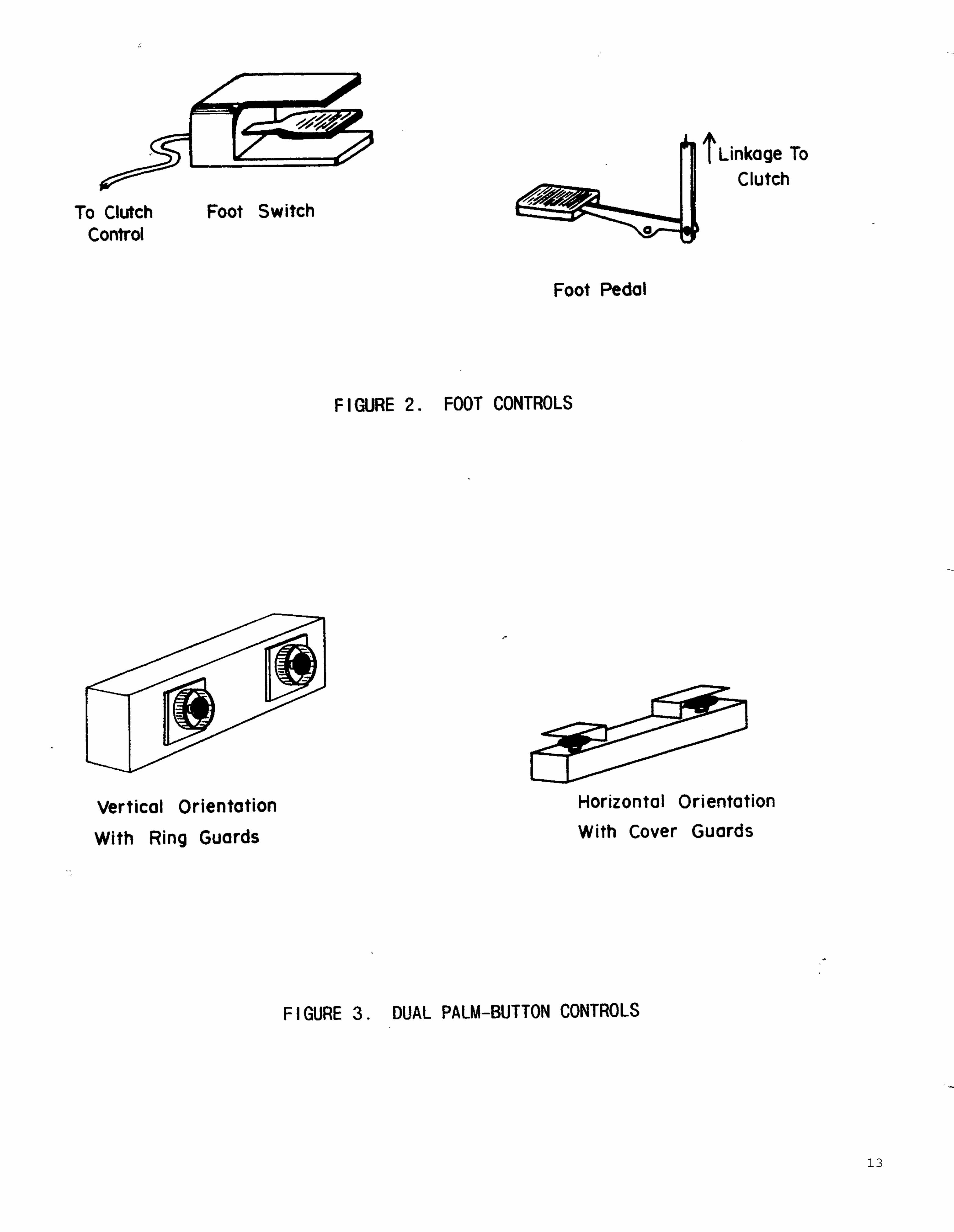
Foot and Hand Controls
Initiation of the power press stroke can be either automatic or manual. On manuallyoperated presses there are two popular modes for initiating machine motion: foot or dualpalm-button (two-hand) controls (see Figures 2 and 3). When foot controls are used, thepress is activated by pressing down on a foot switch or pedal which allows the hands tobe free during the cycling of the press. Foot controls do not intrinsically separate theoperator s hands from the machine’s point of operation during the operating cycle.Person’s operating power presses with foot controls must be protected by safeguardingdevices not always directly linked to machine operation. These safeguarding devices(i.e., barriers, gates, pullouts) may have interlocks capable of controlling initiation of thestroke. However, it also may be possible to operate the press with safeguards removed ormodified so that they do not function as intended.


Section 2 - 14
With dual palm-button controls, once a workpiece is manually positioned in the press,both hands must be removed from the point of operation to depress the palm-buttons.Dual palm-buttons require both hands to be away from the point of operation when thepress cycle is initiated.
Operator productivity may be greater with foot switch operation than with dual palm-button operation since the hands are free during the entire period of the press cycle.However, this freedom of hand movement also places operators using foot switches atgreater potential risk of sustaining a point-of-operation injury.
STANDARDS
Existing OSHA Standards for Foot-Controlled Power Presses
The following is a summary of OSHA standards for mechanical power presses using footcontrols (29 CFR 1910.217).
• OSHA 1910.217(b)(3)(i) -- Manually fed mechanical power presses shallincorporate a single-stroke (or anti-repeat) feature that allows the clutch toengage and the press to cycle only once each time the foot control isdepressed.
• OSHA 1910.217(b)(4)(i) -- A guard shall be used to protect the foot pedal
against accidental operation from falling or moving objects or from anotherperson accidentally stepping on the control.
• OSHA 1910.217(b)(4)(ii) -- A pad with a nonslip contact area shall be firmly
attached to the foot pedal. • OSHA 1910.217(b)(4)(iii) -- The pedal return spring(s) shall be of the
compression type, operating on a rod or guided within a hole or tube, ordesigned to prevent interleaving of spring coils in the event of breakage. Adouble compression spring (one spring inside another with each spring woundin the opposite direction) is one way to meet this replacement.
Existing OSHA Standard for Dual Palm-Button Controlled Power Presses The following is a summary of OSHA standards for mechanical power presses using dualpalm-button controls (29 CFR 1910.217).
• OSHA 1910.217(b)(7)(v)(v) -- Mechanical power presses shall incorporate asingle-stroke (or anti-repeat) feature that allows the clutch to engage and thepress to cycle only once each time the dual palm-buttons are depressed.
• OHSA 1910.217(b)(7)(v)(a) -- Dual palm-buttons shall incorporate an anti-
tie-down feature. This feature allows the buttons to be wired so that they must

Section 2 - 15
both be depressed and released for each cycle of the press. This eliminates thepossibility that operators will “tie-down” one of the palm-buttons, permittingthe use of only one button to cycle the press.
• OSHA 1910.217(b)(7)(v)(a) -- Both palm-buttons shall have guards to prevent
unintended operation and separation between buttons to prevent “bridging” ofthe palm-buttons by operators --i.e., activating the press without using bothhands.
• OSHA 1910.217(c)(3)(vii)(c) -- To reduce the “after-reach” hazard, a
minimum safety distance between the point of operation the dual palm-buttonsshall be maintained on mechanical power presses based on the followingformula:
D = 1.6 m/sec x T (sec), or D = 63 in./sec x T (sec)
The safety distance, D, is the minimum safe distance between the point ofoperation and the palm-button. The 1.6 m/sec (63 in./sec) value is a hand-speed constant that represents the typical speed at which workers can performa hand movement toward the point of operation. The hazard time, T,represents the time required to eliminate the point-of-operation hazard on thepress. On presses with part-revolution clutches, the hazard time is defined asthe stopping time of the press ram. On presses with full-revolution clutches(1910.217(c)(3)(viii)), the hazard time is defined as the maximum possibletime required for the ram to complete one downstroke.
• OSHA 1910.217(e)(1)(i) -- The safety distance shall be maintained for each
die used on the press; it should be checked periodically and at each new dieset-up to ensure that operators are adequately protected. The most accuratemethod of measuring the hazard time on power pressed equipped with part-revolution clutches is through the use of a stop-time meter. This deviceaccurately measures the time that it takes the ram to stop after the palm-buttons of a press have been released --i.e., after the stop signal has beeninitiated.
• OSHA 1910.217(e)(1)(ii) -- On presses with part-revolution clutches, the
clutch/brake mechanism shall be checked periodically for wear andadjustment. Dangerously worn or maladjusted brakes shall be replaced orrepaired before further use of the press. Brake monitors, which are devicesthat monitor the stopping performance of the brake, shall be installed asrequired.
HAZARDS OF POWER PRESS OPERATION Information taken from:

Section 2 - 16
USDL News Release: 97-73 Wednesday, March 5, 1997 Contact: Susan Hall Fleming, (202) 219-8151
OSHA Aims To Reduce Power Press Injuries
Industries with high rates of amputations and other injuries related to power press hazardsare being targeted for special enforcement and education emphasis by the OccupationalSafety and Health Administration (OSHA), the agency announced today. Ten manufacturing industries, which include more than 22,000 establishments andemploy more than one million workers, will receive special focus. These industriesexperienced more than 650 amputations in 1994 (the most recent data available)--nearly10 percent of all amputations in manufacturing. Local offices may expand the programto include other industries. “It is unconscionable for workers to be losing their fingers and suffering other disablinginjuries simply because mechanical power presses are not properly guarded ormaintained,” said Greg Watchman, acting assistant secretary of labor for occupationalsafety and health. “Operating a mechanical power press can be extremely dangerous.Yet injuries are preventable when employers ensure that guards, which have long beenrequired and are readily available, are installed and maintained on presses to protectworkers against the punching action of metal stamping equipment.” OSHA standards require employers to report all point-of-operation injuries. Guardingdevices, weekly and periodic press inspections, training for press operators andmaintenance personnel and regular press maintenance are critical to preventing injuries.OSHA estimates that about 300,000 power presses are in use across the country today. In addition to the human suffering and loss associated with amputations and relatedinjuries, employers are paying anywhere from $5,500 to $47,000 in workers’compensation costs and indirect costs for each of the injuries. During inspections over the past three years, OSHA identified more than 2,650 allegedviolations of power press guarding and inspection requirements. Eighty percent of theseviolations were classified as serious, willful or repeat, indicating the grave threat toworker safety posed by the violations. On poorly safeguarded presses, foot switches can be inadvertently activated while theworkers’ hands are at the point of operation, resulting in an injury. A study conducted byNIOSH researchers (Trump and Etherton, 1986) indicated that there is a critical cyclingrate above which the frequency of inadvertent actuation errors increases dramatically asthe cycling rate increases. For the simulated tasks in this study, this critical cycling ratewas 17.5 strokes/min. These results indicated that jobs on foot-activated presses should

Section 2 - 17
be evaluated to identify their critical cycling rate and steps should be taken to reduce thehazard of inadvertent actuation due to exceeding that critical cycling rate. Trump andEtherton concluded that at operational speeds in excess of a critical cycling rate“...operators performing repetitive tasks begin gradually to lose effective control overtheir foot movements.” Trump and Etherton (1985) also concluded that two factors interact to cause inadvertentmachine activation. First, “unmediated hand movements” are made in response toworkpiece and machine problems. In other words, the operator may attempt to correctthe placement of a workpiece after the downstroke of the press has been initiated.Second, out-of-sequence foot movements may be caused by loss of operator balance orby a breaking of the normal task rhythm. Safeguards used on foot-controlled mechanical power presses include pullout andrestraint devices. These consist of attachments to the wrists that pull the hands awayfrom or hold them outside the danger point. Barrier guards or gates that prevent entryinto the working zone of the press during the downstroke are also used. On pressesequipped with part-revolution clutches, another safeguard used is the presence-sensingdevice. These devices initiate a stop signal if the effective sensing field is penetrated.The two most common types of presence-sensing devices are photoelectric and radiofrequency (capacitance). The safety theory supporting the use of dual palm-buttons can be defeated if operators areable to place their hands into the point-of-operation after the press cycle has beeninitiated, i.e., reach between the dies while they are closing. One way this may occur iswhen dual palm-buttons are located so close to the machine dies that workers can placetheir hands into the working zone of the press before the ram has completed thedownstroke. This type of movement is commonly called the after-reach hazard. NIOSHresearchers have demonstrated that the physical location and orientation of dual palm-buttons in relation to the point-of-operation, as well as the operator’s hand speed, have asignificant effect on an operator’s ability to “after-reach” (Pizatella and Moll, 1987;Horton et al., 1986). Present OSHA standards do not account for differences in handspeed, as a result of, palm-button location and orientation nor press operators capable ofattaining hand speeds in excess of the current OSHA hand-speed constant of 1.6 m/sec(63 in./sec) (Pizatella and Moll, 1987). Table 1 lists the sample of power press operatorsworking on a press simulator controlled by dual palm-buttons. The data in Table 1 wasobtained at two palm-button locations: waist level and shoulder level, both with verticalorientation.

Section 2 - 18
Several significant points are demonstrated by the data in Table 1. The results of thisstudy (analyzed by an analysis of variance procedure) generally indicate that as a group,male workers have faster hand speed than female workers (P<0.01). Also, based onDuncan’s Multiple Range Test, younger workers (under 31) have faster hand speed thanolder workers (P<0.01). Further, 28% of all subjects, 40% of males and 12% of females,exceeded the OSHA standard of 1.6 m/sec (63 ins./sec). Of males under 31, 79%exceeded the OSHA standard. The fastest hand speed measured was 3.65 m/sec (142in./sec), more than twice the hand speed specified in the OSHA standard. Finally,locating the palm-buttons at shoulder level did not significantly alter the operator’s abilityto exceed the 1.6 m/sec (63 in./sec) standard. Thus, based on these data, compliance withthe current OSHA hand-speed standard may not be providing adequate protection for allpower press operators.

Section 2 - 19
Max
3.63
2.21
1.86
2.97
3.63
2.15
1.86
3.06
1.41
3.06
3.63
2.21
3.06
2.97
3.63
Ran
ge
Min
.
1.01
0.53
0.72
0.56
0.53
0.38
0.81
0.49
0.48
0.48
0.38
0.53
0.49
0.48
0.38
N
24 18 8 12 62 14 8 20 16 58 38 26 28 28 120
SD
0.68
0.46
0.43
0.62
0.72
0.46
0.36
0.67
0.30
0.52
0.78
0.44
0.60
0.54
0.68
Com
bine
d
Mea
n
2.13
1.13
1.25
1.41
1.58
1.10
1.36
1.15
0.81
1.07
1.75
1.20
1.18
1.07
1.34
N
12 9 4 6 31 7 4 10 8 29 19 13 14 14 60
SD
0.68
0.47
0.41
0.71
0.70
0.27
0.37
0.62
0.30
0.45
0.78
0.44
0.56
0.62
0.65
Shou
lder
-leve
l loc
atio
n
Mea
n
2.18
1.28
1.38
1.70
1.71
1.07
1.48
1.23
0.97
1.16
1.77
1.32
1.27
1.28
1.45
N**
12 9 4 6 31 7 4 10 8 29 19 13 14 14 60
SD§
0.70
0.44
0.48
0.38
0.73
0.63
0.35
0.74
0.20
0.57
0.81
0.41
0.66
0.36
0.70
Wai
st-le
vel l
ocat
ion
Mea
n
2.09
1.01
1.18
1.11
1.46
1.13
1.23
1.07
0.66
0.99
1.73
1.08
1.08
0.85
1.23
†
To c
onve
rt to
in./s
ec, m
ullti
ply
met
ers b
y 39
.37
Adap
ted
from
Piz
atel
la a
nd M
oll (
1987
) St
anda
rd D
evia
tion
Num
ber
Tab
le 1
Mea
n af
ter-
reac
h ha
nd sp
eed
(m/s
)* b
y pa
lm-b
utto
n lo
catio
n, g
ende
r an
d ag
e †
Gen
der
and
age
Mal
e: 20
-30
31-4
0 41
-50
51-6
0 T
otal
Fem
ale:
20-3
0 31
-40
41-5
0 51
-60
Tot
al
Com
bine
d: 20
-30
31-4
0 41
-50
51-6
0
Agg
rega
te:
* † § **

Section 2 - 20
Since this study identified young male press operators as having hand speeds faster thanother press operators, an analysis of epidemiological data should indicate that young malepress operators have a larger amputation rate. To examine this possibility, NIOSHinvestigators undertook an analysis of injury data from State workers’ compensationagencies (Jensen and Sinkule, in press). Injury data from 29 states was used to compareamputation injury incidence rates (IR) for power press operators to identify anydifferences due to gender and age. While this analysis indicated that gender did notsignificantly affect the IR, there were differences in the IR based on age. The IR foryoung male press operators was compared to the IR of all other press operators. The IRfor young male press operators was 1.91 cases/1,000 press operators while the IR for allother press operators was 1.58. Data from the state of Ohio was analyzed separatelybecause of some recordkeeping differences. The Ohio data demonstrated a moredramatic difference in the IR among press operators. The IR for young male pressoperators in Ohio was 4.09 cases/1,000 press operators as compared to an IR of 1.41 forall other press operators. Although data analysis is not definitive in establishing thatyoung male press operators are at a greater risk of injury, the differences in IR are in adirection consistent with the premise that young male press operators are not beingadequately protected with present safeguarding mechanisms. To enhance the protection provided to all press operators, emphasis should be placed onensuring the proper use of existing point-of-operating safeguards and the development ofimproved safeguards. Based on these findings, NIOSH concludes that even thought there are existing OSHAstandards, a significant risk of injury to power press operators remains. Operators are not always protected by the safeguarding provided because there are widevariations in hand speed among males, females, younger workers and older workers. Inaddition to variation in hand speed there are several reasons why existing safeguardingmay not provide the desired protection, such as:
• On machines that stamp differently shaped parts, each of which needs adifferent guard, it may take more time to install the proper safeguarding than ittakes to run the job.
• Operators sometimes defeat the purpose of safeguards by removing oroverriding them for convenience or increased productivity.
• Safeguarding is not always adjusted properly. This may be a problem withpullout and restraint devices if workers with different hand sizes and armlengths work on consecutive shifts at the same machine. In some cases, dualpalm-buttons may be located too close to the point of operation because use ofthe existing hand-speed constant leads to erroneous placement of the palm-buttons. Also, two-hand controls or presence-sensing devices may beimproperly located after dies are changed.

Section 2 - 21
CONCLUSIONS Even though there is an existing OSHA standard that addresses construction andoperation of mechanical power presses, injuries and amputations among press operatorsare still occurring with alarming frequency. In many cases, these injuries occur when thepress is inadvertently activated while the operator’s hands are in the operating zone of thepress. The results of a recent experiment conducted by NIOSH researchers indicate thatthe chance for inadvertent press activation (possibly involving injury) may increase as thecycling rate increases (Trump and Etherton, 1986). Injuries occur as a result of “after-reach” among operators who initiate power pressesusing dual palm-buttons. Therefore, attention should be given to the individualoperator’s hand speed, keeping in mind that, in general, hand speed may be a function ofage and gender. The recommendations contained in the CIB are intended to address these problems andthereby reduce injuries among mechanical power press operators. RECOMMENDATIONS The following recommendations were compiled from generally accepted safety practicesand research; they are intended to supplement existing OSHA standards. Implementationof these recommendations should be considered in any comprehensive safety program forthe prevention of injuries among mechanical power press operators. We wish toemphasize that these data from NIOSH studies demonstrate that hand speed may be aninappropriate measure on which to base a safety distance standard for operation ofmechanical power presses. It may be impractical to implement a single hand-speed constant that would protect allworkers under all power press set-ups. Implementation of such a hand-speed standardwould render dual palm-buttons practically useless as a safeguarding device due to thelong safety distances that would result. Foot-Controlled Power Presses
• Foot controls should be used with point-of-operation safeguards that cannot beeasily bypassed or misadjusted.
• Interlocking safeguards should be considered so that the foot control is
inoperable when the safeguards are not functioning. • An ergonomically correct, sitting work position, if possible, is preferred over a
standing position, if a foot control is used. • To reduce strain on the foot, a foot-rest should be provided near the pedal.

Section 2 - 22
• Riding the pedal (keeping the foot on the pedal without actually depressing it)is hazardous, and standard operating procedures should note this unacceptablework practice.
• The rate at which presses are being cycled should be monitored periodically to
ensure that operators are not working at a pace that leads to inadvertentpressing of the foot pedal.
Power Presses Controlled with Dual Palm-Buttons
• Because full-revolution clutches cannot be stopped once they are activated,they should only be used on presses with short downstroked or fast cyclingrates.
• To reduce musculoskeletal stress to the wrist, arms and shoulders of press
operators, ergonomic job design principles should be considered whenlocating and/or orienting dual palm-buttons in relation to the point-of-operation.
• Caution must be exercised in evaluating each power press set-up and
operating to ensure that an adequate safety distance is maintained at all times.Employers should consider evaluating individual press operators to determineif they are exceeding the current OSHA hand-speed constant. If a worker isidentified as being capable of exceeding the hand-speed constant, morepositive means of point-of-operation safeguarding should be considered, suchas fixed barrier guards.

Section 2 - 23
Just What is Control Reliability?
How are mechanical Power Press controls different than other types of controls?
Mechanical Power Press controls are designed to act a special way when they fail. If thecontrols fail they must:
1. Not prevent the normal stopping action from being applied to the press whenrequired.
2. Prevent initiation of a successive stroke until the failure is corrected.3. Detect the failure by a simple test or be indicated by the control system.
When is Control reliability required?
1. When a two-hand control or presence sensing device or Type B Gate is used as ameans of “Point of Operation guarding” on a “part revolution clutch press”
2. When hands are in the die operation.

Section 2 - 24
OSHA 1910.217 CONTROL COMPLIANCE CHECK LIST FORPOWER PRESSES
1910.217 (B)(7)(i) Check braking performance.
(ii) Check presence and function of red stop control.
(iii) Observe supervisory selection for off, inch, ss, cont.
(iv) Observes that inch means requires two-hand operation or provides protection by location or the presence sensing device.
(v) Test the two-hand control to insure a single arm combination cannot be used to initiate stroking.
(vii) Observes supervisory control and presence of complete control sets for multiple operators.
(viii) Check for continuous prior act switch.
(ix) Check for hand/foot supervisory control
(x) Insure foot switch is guarded.
(xi) Check for dual monitored solenoid valve.
(xii) Check schematic for motor forward contact.
(xiii) &(xiv) Check for clutch and counterbalance pressure switch.
(b)(8)(i) Check for main power disconnect with lockable off switch.
(iii) Check motor starter for under voltage protection.
(v) Check for Ground Fault Indicator Control
(vi) & (13) Check for control reliability (multiple relays (4-6), 4-6 cam rotary limit, chain break or motion detection, schematic and record of control changes.
(b) & (14) Check for brake monitoring as required by (c) 5 (HID with two-hand control, type B gate or presence sensing).

Section 2 - 25
Recommended Checklist for Safe Operation of Mechanical Power Presses
The checklists presented below are provided as an adjunct to the above recommendationsto aid in maintaining safe use of foot and dual palm-button controls for mechanical powerpresses.
Checklist to be used when foot controls are used:
_____ Safeguards are in place that will prevent injury if the foot control is inadvertently depressed.
_____ A guard or cover is over the foot switch to prevent activation by fallen objects.
_____ The working posture is as nonfatiguing as possible. Seating is provided where possible.
_____ Presence-sensing devices, if used, are properly maintained and aligned to ensure that the sensing field is effectively safeguarding the point-of-operation.
_____ Work rules have been established against riding the foot pedal.
_____ A check has been made to see if operators inadvertently push the foot switch because they are working at a high cycling rate with the foot control.
_____ The brake monitor, if required, is operative.
_____ The foot control must be depressed and released once before the press can be cycled again.
_____ Safeguarding devices and procedures are available for die set-up and maintenance to prevent or arrest an inadvertent downstroke of the ram.
_____ The press is routinely and frequently inspected and properly maintained.

Section 2 - 26
Checklist to be used when dual palm-buttons are used:
_____ The palm-buttons are installed to meet at least the OSHA minimum safety distance requirements. Greater distances are recommended based on the operator’s true hand speed.
_____ The palm-buttons are installed to reduce undue operator fatigue.
_____ The palm-buttons are protected against unintended operation and are arranged so that the only probable means of operation is by both hands of a single worker or by both hands of each operator, where more than one operator is being protected by dual palm-buttons.
_____ On presses with part-revolution clutches, the removal of a worker’s hand from any palm-button during the downstroke of the ram quickly deactivates the clutch and applies the brake to stop ram motion.
_____ The brake monitor, if required, is operable.
_____ All palm-buttons must be released before an interrupted stroke can be resumed or the press can be cycled again.
_____ The palm-buttons are fixed in a position so that only a set-up person, supervisor or safety engineer can move them.
_____ The position of the palm-buttons is arranged to prevent any part of the body from entering the working zone of the press during the downstroke.
_____ The operation of the press is monitored frequently to ensure that operators are not bypassing or defeating the safety features of the dual palm-buttons.
_____ Safeguarding devices and procedures are available for die set-up and maintenance to prevent or arrest an inadvertent downstroke of the ram.
_____ Presence-sensing devices, if used, are properly maintained and aligned to ensure that the sensing field is effectively safeguarding the point-of-operation.
_____ The press is routinely and frequently inspected and properly maintained.

Section 2 - 27
PRESS EVALUATION FORM
1. Manufacturer: _____________________________________________________ 2. Press Number: _____________________________________________________ 3. Serial Number: ____________________________________________________ 4. Tonnage: _________________________________________________________ 5. Length of Stroke: __________________________________________________ 6. Is the flywheel, gears, etc. guarded 7 feet above working surface? _____ YES _____ NO 7. Type of clutch? ____________________________________________________ 8. Spring counterbalance _____ DNA _____ YES Is it guarded _____ YES _____ NO 9. Air counterbalance _____ DNA _____ YES 10. Is there an air counterbalance “weight and pressure” chart on the press? _____ YES _____ NO If NO, how do they set the pressure? ____________________________________ __________________________________________________________________ __________________________________________________________________ 11. Can the air counterbalance hold the slide and attachments at any point in the stroke
without help from the machine brake? _____ YES _____ NO _____ NOT KNOWN 12. Number of surge tanks: _______________________________________________ Surge tanks for: _____ Air clutch/Brake* _____ Air counterbalance _____ Air _____________ 13. Are surge tanks drained?: _____ YES _____ NO

Section 2 - 28
14. Number of air pressure switches?: (If none, explain why) __________________________________________________________________ __________________________________________________________________ Are they labeled? _____ YES _____ NO Are pressure switches for: _____ Air counterbalance* _____ Clutch/brake* _____ Die cushion _____ Tonnage monitor 15. Are the pressure switches set so if the air is not adequate or the pressure drops, the
press will be inoperable? _____ YES _____ NO 16. Dual solenoid air valve and muffler with a pneumatic or electrical monitor. _____ YES ` _____ NO (using both is best) 17. Air controlling equipment: A. filter B. regulator/gauge clean _____ Yes _____ NO Damaged _____ YES _____ NO C. Lubricator _____ Full _____ Empty 18. Brake lining worn or excessive grease on brake lining: _____ YES _____ NO _____ Cannot visually see 19. Does brake make excessive noise? _____ YES _____ NO 20. Is electrical wiring properly installed? _____ YES _____ NO 21. Main power disconnect capable of being locked in the off position only. _____ YES _____ NO 22. Is it labeled? _____ YES _____ NO 23. Motor start button protected against accidental operation. _____ YES _____ NO 24. Drive motor start (magnetic type). _____ YES _____ NO 25. Ground detector light working? _____ YES _____ NO

Section 2 - 29
26. Does motor forward/reverse key selector switch exist? _____ YES _____ NO Who has control of the key? _____________________________________________ 27. How is press presently being operated when in the following mode(s):. Inch `Single Stroke Continuous Hand Buttons ____ _____ _____ Foot Pedal ____ _____ _____ 5 to 30 sec. delay switch ____ _____ _____ *Separate controls ____ _____ _____ Light curtain ____ _____ _____ *Explain________________________________________________________________
_________________________________________________________________ 28. Is the control selector for -- Off, Inch, Single Stroke, and Continuos, a key switch? _____ YES _____ NO Who has control of the key? _____________________________________________ 29. IS the control selector for hand or foot control a key switch? _____. YES _____ NO Who has control of the key? _____________________________________________ 30. Is the point-of-operation protected? _____ YES _____ NO If yes, how is it protected?
__________________________________________________________________________________________________________________________________________
31. Does it meet the safety distance? _____ YES _____ NO _____ Has not been checked Distance: __________________ 32. Are guards needed on the side and back of the press? _____________________________________________________________________ 33. If the press has a variable speed motor was the safety distance checked at high speed? _____ DNA _____ YES _____ NO _____ Has not been checked

Section 2 - 30
34. Two hand controls _____ DNA _____ YES YES NO _____ _____ Protected against unintended operation? _____ _____ Separate 22 to 27 inches? _____ _____ Secured in place? _____ _____ Is concurrent pressure required on both hand controls? _____ _____ Two hand control anti-repeat working? _____ _____ Does the operator need to release all hand controls before an interrupted stroke can be resumed? _____ _____ Does the control system require two-hand controls when used on
multiple-station presses, and a separate set of controls for each designated employee?
_____ _____ DOES EMERGENCY STOP WORK? _____ _____ Is the emergency stop button RED? _____ _____ If top stop button is present, is it YELLOW? 35. Foot pedal? _____ DNA _____ YES YES NO _____ _____ Protected against unintended operation? _____ _____ Anti-repeat? _____ _____ Requires operator to remove his/her foot off treadle before another
stroke can be made? _____ _____ With the foot switch selected press should not operate in the inch
mode. 36. Is this a hand-in-die operation? _____ YES _____ NO 37. If NO, what type of point-of-operation guard is being used?
__________________________________________________________________________________________________________________________________________
38. If YES, is press guarded with two-hand control, presence-sensing device, type B gate
or movable barrier guard? _____ YES _____ NO

Section 2 - 31
39. IF YES to #38, is brake monitor and control reliability present? _____ YES _____ NO YES NO _____ _____ Does the control reliability include that no failure in the control
system prevent normal stopping action from occurring and no successive stroke be initiated unless the failure is cleared?
_____ _____ Does the control system also include a motion detector to detect chain or cam shaft failure?
_____ _____ Does the brake monitor, monitor brake performance at least once each stroke?
_____ _____ Are the cams and contract points inspected for cracks, wear or damaged points?
40. Are hand tools provided? _____ YES _____ NO 41. Are safety blocks provided? _____ YES _____ NO Are they used? _____ YES _____ NO 42. Are dies marked? _____ YES _____ NO Total weight _____________ Tonnage _________________ Upper weight _____________ Stroke height _________________ 43. Are there two means of attaching dies? _____ YES _____ NO 44. Is the dies material handling equipment adequate?
_____ YES _____ NO If NO, explain:________________________________________________________________________________________________________________________________________________________________________________________________________________________________________________________________________________________________________________________________________________________________________________________________________________________________________________________________________________________________________________________________________________________________________________________________________________________________________________________________________________________________________________________________________________


Standards and Interpretations


Section 3 - 1
1910.217Mechanical Power Presses
Subpart OSubpart Title Machinery and Machine Guarding
1910.217(a) -- General requirements.
1910.217(a)(1) -- [Reserved]
1910.217(a)(2) -- [Reserved]
1910.217(a)(3) -- [Reserved]
1910.217(a)(4) -- Reconstruction and modification. It shall be the responsibility of any personreconstructing, or modifying a mechanical power press to do so in accordance with paragraph(b) of this section.
1910.217(a)(5) -- Excluded machines. Press brakes, hydraulic and pneumatic power presses,bulldozers, hot bending and hot metal presses, forging presses and hammers, riveting machinesand similar types of fastener applicators are excluded from the requirements of this section.
1910.217(b) -- Mechanical power press guarding and construction, general -
1910.217(b)(1) -- Hazards to personnel associated with broken or falling machine components.Machine components shall be designed, secured, or covered to minimize hazards caused bybreakage, or loosening and falling or release of mechanical energy (i.e. broken springs).
1910.217(b)(2) -- Brakes. Friction brakes provided for stopping or holding a slide movementshall be inherently self-engaging by requiring power or force from an external source to causedisengagement. Brake capacity shall be sufficient to stop the motion of the slide quickly andcapable of holding the slide and its attachments at any point in its travel.
1910.217(b)(3) -- Machines using full revolution positive clutches.
1910.217(b)(3)(i) -- Machines using full revolution clutches shall incorporate a single-strokemechanism.
1910.217(b)(3)(ii) -- If the single-stroke mechanism is dependent upon spring action, thespring(s) shall be of the compression type, operating on a rod or guided within a hole or tube,and designed to prevent interleaving of the spring coils in event of breakage.
1910.217(b)(4) -- Foot pedals (treadle).

Section 3 - 2
1910.217(b)(4)(i) -- The pedal mechanism shall be protected to prevent unintended operationfrom falling or moving objects or by accidental stepping onto the pedal.
1910.217(b)(4)(ii) -- A pad with a nonslip contact area shall be firmly attached to the pedal.
1910.217(b)(4)(iii) -- The pedal return spring(s) shall be of the compression type, operating ona rod or guided within a hole or tube, or designed to prevent interleaving of spring coils in eventof breakage.
1910.217(b)(4)(iv) -- If pedal counterweights are provided, the path of the travel of the weightshall be enclosed.
1910.217(b)(5) -- Hand operated levers.
1910.217(b)(5)(i) -- Hand-lever-operated power presses shall be equipped with a spring latchon the operating lever to prevent premature or accidental tripping.
1910.217(b)(5)(ii) -- The operating levers on hand-tripped presses having more than oneoperating station shall be interlocked to prevent the tripping of the press except by the"concurrent" use of all levers.
1910.217(b)(6) -- Two-hand trip.
1910.217(b)(6)(i) -- A two-hand trip shall have the individual operator's hand controlsprotected against unintentional operation and have the individual operator's hand controlsarranged by design and construction and/or separation to require the use of both hands to tripthe press and use a control arrangement requiring concurrent operation of the individualoperator's hand controls.
1910.217(b)(6)(ii) -- Two-hand trip systems on full revolution clutch machines shall incorporatean antirepeat feature.
1910.217(b)(6)(iii) -- If two-hand trip systems are used on multiple operator presses, eachoperator shall have a separate set of controls.
1910.217(b)(7) -- Machines using part revolution clutches.
1910.217(b)(7)(i) -- The clutch shall release and the brake shall be applied when the externalclutch engaging means is removed, deactivated, or deenergized.

Section 3 - 3
1910.217(b)(7)(ii) -- A red color stop control shall be provided with the clutch/brake controlsystem. Momentary operation of the stop control shall immediately deactivate the clutch andapply the brake. The stop control shall override any other control, and reactuation of the clutchshall require use of the operating (tripping) means which has been selected.
1910.217(b)(7)(iii) -- A means of selecting Off, "Inch," Single Stroke, and Continuous (whenthe continuous function is furnished) shall be supplied with the clutch/brake control to select typeof operation of the press. Fixing of selection shall be by means capable of supervision by theemployer.
1910.217(b)(7)(iv) -- The "Inch" operating means shall be designed to prevent exposure of theworkers hands within the point of operation by:
1910.217(b)(7)(iv)(a) -- Requiring the concurrent use of both hands to actuate the clutch, or
1910.217(b)(7)(iv)(b) -- Being a single control protected against accidental actuation and solocated that the worker cannot reach into the point of operation while operating the singlecontrol.
1910.217(b)(7)(v) -- Two-hand controls for single stroke shall conform to the followingrequirements:
1910.217(b)(7)(v)(a) -- Each hand control shall be protected against unintended operation andarranged by design, construction, and/or separation so that the concurrent use of both hands isrequired to trip the press.
1910.217(b)(7)(v)(b) -- The control system shall be designed to permit an adjustment whichwill require concurrent pressure from both hands during the die closing portion of the stroke.
1910.217(b)(7)(v)(c) -- The control system shall incorporate an antirepeat feature.
1910.217(b)(7)(v)(d) -- The control systems shall be designed to require release of alloperators' hand controls before an interrupted stroke can be resumed. This requirement pertainsonly to those single-stroke, two-hand controls manufactured and installed on or after August 31,1971.
1910.217(b)(7)(vi) -- [Reserved]

Section 3 - 4
1910.217(b)(7)(vii) -- Controls for more than one operating station shall be designed to beactivated and deactivated in complete sets of two operator's hand controls per operating stationby means capable of being supervised by the employer. The clutch/brake control system shallbe designed and constructed to prevent actuation of the clutch if all operating stations arebypassed.
1910.217(b)(7)(viii) -- Those clutch/brake control systems which contain both single andcontinuous functions shall be designed so that completion of continuous circuits may besupervised by the employer. The initiation of continuous run shall require a prior action ordecision by the operator in addition to the selection of Continuous on the stroking selector,before actuation of the operating means will result in continuous stroking.
1910.217(b)(7)(ix) -- If foot control is provided, the selection method between hand and footcontrol shall be separate from the stroking selector and shall be designed so that the selectionmay be supervised by the employer.
1910.217(b)(7)(x) -- Foot operated tripping controls, if used, shall be protected so as toprevent operation from falling or moving objects, or from unintended operation by accidentalstepping onto the foot control.
1910.217(b)(7)(xi) --The control of air-clutch machines shall be designed to prevent asignificant increase in the normal stopping time due to a failure within the operating valuemechanism, and to inhibit further operation if such failure does occur. This requirement shallapply only to those clutch/brake air-valve controls manufactured and installed on or after August31, 1971, but shall not apply to machines intended only for continuous, automatic feedingapplications.
1910.217(b)(7)(xii) -- The clutch/brake control shall incorporate an automatic means toprevent initiation or continued activation of the Single Stroke or Continuous functions unless thepress drive motor is energized and in the forward direction.
1910.217(b)(7)(xiii) -- The clutch/brake control shall automatically deactivate in event of failureof the power or pressure supply for the clutch engaging means. Reactivation of the clutch shallrequire restoration of normal supply and the use of the tripping mechanism(s).
1910.217(b)(7)(xiv) -- The clutch/brake control shall automatically deactivate in event of failureof the counterbalance(s) air supply. Reactivation of the clutch shall require restoration of normalair supply and use of the tripping mechanism(s).
1910.217(b)(7)(xv) -- Selection of bar operation shall be by means capable of beingsupervised by the employer. A separate pushbutton shall be employed to activate the clutch,and the clutch shall be activated only if the driver motor is deenergized.

Section 3 - 5
1910.217(b)(8) -- Electrical.
1910.217(b)(8)(i) -- A main power disconnect switch capable of being locked only in the Offposition shall be provided with every power press control system.
1910.217(b)(8)(ii) -- The motor start button shall be protected against accidental operation.
1910.217(b)(8)(iii) -- All mechanical power press controls shall incorporate a type of drivemotor starter that will disconnect the drive motor from the power source in event of controlvoltage or power source failure, and require operation of the motor start button to restart themotor when voltage conditions are restored to normal.
1910.217(b)(8)(iv) -- All a.c. control circuits and solenoid value coils shall be powered by notmore than a nominal 120-volt a.c. supply obtained from a transformer with an isolatedsecondary. Higher voltages that may be necessary for operation of machine or controlmechanisms shall be isolated from any control mechanism handled by the operator, but motorstarters with integral Start-Stop buttons may utilize line voltage control. All d.c. control circuitsshall be powered by not more than a nominal 240-volt d.c. supply isolated from any highervoltages.
1910.217(b)(8)(v) -- All clutch/brake control electrical circuits shall be protected against thepossibility of an accidental ground in the control circuit causing false operation of the press.
1910.217(b)(8)(vi) -- Electrical clutch/brake control circuits shall incorporate features tominimize the possibility of an unintended stroke in the event of the failure of a control componentto function properly, including relays, limit switches, and static output circuits.
1910.217(b)(9) -- Slide counterbalance systems.
1910.217(b)(9)(i) -- Spring counterbalance systems when used shall incorporate means toretain system parts in event of breakage.
1910.217(b)(9)(ii) -- Spring counterbalances when used shall have the capability to hold theslide and its attachments at midstroke, without brake applied.
1910.217(b)(9)(iii) -- Air counterbalance cylinders shall incorporate means to retain the pistonand rod in case of breakage or loosening.
1910.217(b)(9)(iv) -- Air counterbalance cylinders shall have adequate capability to hold theslide and its attachments at any point in stroke, without brake applied.
1910.217(b)(9)(v) -- Air counterbalance cylinders shall incorporate means to prevent failure ofcapability (sudden loss of pressure) in event of air supply failure.

1910.217(b)(10) -- Air controlling equipment. Air controlling equipment shall be protected against foreign material and water entering the pneumatic system of the press. A means of air lubrication shall be provided when needed.
1910.217(b)(11) -- Hydraulic equipment. The maximum anticipated working pressures in any hydraulic system on a mechanical power press shall not exceed the safe working pressure rating of any component used in that system.
1910.217(b)(12) -- Pressure vessels. All pressure vessels used in conjunction with power presses shallconform to the American Society of Mechanical Engineers Code for Pressure Vessels, 1968 Edition,which is incorporated by reference as specified in Sec. 1910.6. 1910.217(b)(13) – Control reliability. When required by paragraph (c)(5) of this section, the controlsystem shall be constructed so that a failure within the system does not prevent the normal stopping action from being applied to the press when required, but does prevent initiation of a successive strokeuntil the failure is corrected. The failure shall be detectable by a simple test, or indicated by the control system. This requirement does not apply to those elements of the control system which have no effecton the protection against point of operation injuries.
What is Control Reliability
• It is a control system that will detect any failure within the system;
• It will not prevent the normal stopping action from being applied to the press;
• But will prevent initiation of successive stroke;
• Failure will be detectable or indicated by the control system.
__________________________________________________________________________________________________________Section 3 - 6

CONTROL RELIABILITY-WHEN IS IT REQUIRED
• It must be a part revolution press• Operator must have hands in die• The press must be guarded by:
– Presence sensing device– Two hand control– Type B gate guard– Movable barrier guard
(b)(4) Brake system monitoring. When required by paragraph (c) (5) of this section, the brake monitor shall meet the following requirements: (b)(4)(i) Be so constructed as to automatically prevent the activation of a successive stroke if the stopping time or braking distance deteriorates to a point where thesafety distance being utilized does not meet the requirements set forth in paragraph(c)(3)(iii)(e) or (c)(3)(vii)(c) of this section. The brake monitor used with the Type Bgate or movable barrier device shall be installed in a manner to detect slide top-stopoverrun beyond the normal limit reasonably established by the employer. (b)(4)(ii) Be installed on a press such that it indicates when the performanceof the braking system has deteriorated to the extent described in paragraph (b)(14)(i) ofthis section; and (b)(4)(iii) Be constructed and installed in a manner to monitor brake systemperformance on each stroke. ________________________________________________________________________ Section 3-7
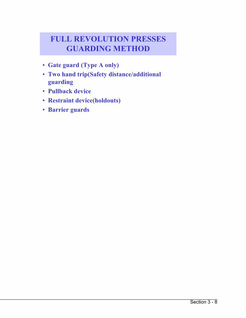
FULL REVOLUTION PRESSES GUARDING METHOD
• Gate guard (Type A only)• Two hand trip(Safety distance/additional
guarding• Pullback device• Restraint device(holdouts)• Barrier guards
__________________________________________________________________________________________________________Section 3 - 8

PART REVOLUTION PRESSES GUARDING METHODS
• Gate guards (Type A and B)• Presence sensing devices
– Light sensing curtains– Radio frequency
• Pullback device• Restraint device(holdouts)• Two-hand controls• Barrier guards
__________________________________________________________________________________________________________Section 3 - 9

Section 3 - 10
1910.217(c) -- Safeguarding the point of operation -
1910.217(c)(1) -- General requirements.
1910.217(c)(1)(i) -- It shall be the responsibility of the employer to provide and insure theusage of "point of operation guards" or properly applied and adjusted point of operation deviceson every operation performed on a mechanical power press. See Table O-10.
1910.217(c)(1)(ii) -- The requirement of paragraph (c)(1)(i) of this section shall not apply whenthe point of operation opening is one-fourth inch or less. See Table O-10.
1910.217(c)(2) -- Point of operation guards.
1910.217(c)(2)(i) -- Every point of operation guard shall meet the following design,construction, application, and adjustment requirements:
1910.217(c)(2)(i)(a) -- It shall prevent entry of hands or fingers into the point of operation byreaching through, over, under or around the guard;
1910.217(c)(2)(i)(b) -- It shall conform to the maximum permissible openings ofTable O-10;
1910.217(c)(2)(i)(c) -- It shall, in itself, create no pinch point between the guard and movingmachine parts;
1910.217(c)(2)(i)(d) -- It shall utilize fasteners not readily removable by operator, so as tominimize the possibility of misuse or removal of essential parts;
1910.217(c)(2)(i)(e) -- It shall facilitate its inspection, and
1910.217(c)(2)(i)(f) -- It shall offer maximum visibility of the point of operation consistent withthe other requirements.
1910.217(c)(2)(ii) -- A die enclosure guard shall be attached to the die shoe or stripper in afixed position.
1910.217(c)(2)(iii) -- A fixed barrier guard shall be attached securely to the frame of the pressor to the bolster plate.
1910.217(c)(2)(iv) -- An interlocked press barrier guard shall be attached to the press frameor bolster and shall be interlocked with the press clutch control so that the clutch cannot beactivated unless the guard itself, or the hinged or movable sections of the guard are in position toconform to the requirements of Table O-10.

Section 3 -11
1910.217(c)(2)(v) -- The hinged or movable sections of an interlocked press barrier guard shallnot be used for manual feeding. The guard shall prevent opening of the interlocked section andreaching into the point of operation prior to die closure or prior to the cessation of slide motion.See paragraph (c)(3)(ii) of this section regarding manual feeding through interlocked pressbarrier devices.
1910.217(c)(2)(vi) -- The adjustable barrier guard shall be securely attached to the press bed,bolster plate, or die shoe, and shall be adjusted and operated in conformity with Table O-10and the requirements of this subparagraph. Adjustments shall be made only by authorizedpersonnel whose qualifications include a knowledge of the provisions of Table O-10 and thissubparagraph.
1910.217(c)(2)(vii) -- A point of operation enclosure which does not meet the requirements ofthis subparagraph and Table O-10 shall be used only in conjunction with point of operationdevices.
1910.217(c)(3) -- Point of operation devices.
1910.217(c)(3)(i) -- Point of operation devices shall protect the operator by:
1910.217(c)(3)(i)(a) -- Preventing and/or stopping normal stroking of the press if theoperator's hands are inadvertently placed in the point of operation; or
1910.217(c)(3)(i)(b) -- Preventing the operator from inadvertently reaching into the point ofoperation, or withdrawing his hands if they are inadvertently located in the point of operation, asthe dies close; or
1910.217(c)(3)(i)(c) -- Preventing the operator from inadvertently reaching into the point ofoperation at all times; or
1910.217(c)(3)(i)(d) -- [Reserved]
1910.217(c)(3)(i)(e) -- Requiring application of both of the operator's hands to machineoperating controls and locating such controls at such a safety distance from the point ofoperation that the slide completes the downward travel or stops before the operator can reachinto the point of operation with his hands; or
1910.217(c)(3)(i)(f) -- Enclosing the point of operation before a press stroke can be initiated,and maintaining this closed condition until the motion of the slide had ceased; or
1910.217(c)(3)(i)(g) -- Enclosing the point of operation before a press stroke can be initiated,so as to prevent an operator from reaching into the point of operation prior to die closure orprior to cessation of slide motion during the downward stroke.

Section 3 -12
1910.217(c)(3)(ii) -- A gate or movable barrier device shall protect the operator as follows:
1910.217(c)(3)(ii)(a) -- A Type A gate or movable barrier device shall protect the operator inthe manner specified in paragraph (c)(3)(i)(f) of this section, and
1910.217(c)(3)(ii)(b) -- A Type B gate or movable barrier device shall protect the operator inthe manner specified in paragraph (c)(3)(i)(g) of this section.
1910.217(c)(3)(iii) -- A presence sensing point of operation device shall protect the operatoras provided in paragraph (c)(3)(i)(a) of this section, and shall be interlocked into the controlcircuit to prevent or stop slide motion if the operator's hand or other part of his body is withinthe sensing field of the device during the downstroke of the press slide.
1910.217(c)(3)(iii)(a) -- The device may not be used on machines using full revolution clutches.
1910.217(c)(3)(iii)(b) -- The device may not be used as a tripping means to initiate slidemotion.
1910.217(c)(3)(iii)(c) -- The device shall be constructed so that a failure within the systemdoes not prevent the normal stopping action from being applied to the press when required, butdoes prevent the initiation of a successive stroke until the failure is corrected. The failure shall beindicated by the system.
1910.217(c)(3)(iii)(d) -- Muting (bypassing of the protective function) of such device, duringthe upstroke of the press slide, is permitted for the purpose of parts ejection, circuit checking,and feeding.
1910.217(c)(3)(iii)(e) -- The safety distance (D(s)) from the sensing field to the point ofoperation shall be greater than the distance determined by the following formula:
D(s) = 63 inches/second X T(s)
where:
D(s) = minimum safety distance (inches); 63 inches/second = hand speed constant;
and
T(s) = stopping time of the press measured at approximately 90 deg. position of crankshaft rotation (seconds).

Section 3 - 13
1910.217(c)(3)(iii)(f) -- Guards shall be used to protect all areas of entry to the point ofoperation not protected by the presence sensing device.
1910.217(c)(3)(iv) -- The pull-out device shall protect the operator as specified in paragraph(c)(3)(i)(b) of this section, and shall include attachments for each of the operator's hands.
1910.217(c)(3)(iv)(a) -- Attachments shall be connected to and operated only by the pressslide or upper die.
1910.217(c)(3)(iv)(b) -- Attachments shall be adjusted to prevent the operator from reachinginto the point of operation or to withdraw the operator's hands from the point of operationbefore the dies close.
1910.217(c)(3)(iv)(c) -- A separate pull-out device shall be provided for each operator if morethan one operator is used on a press.
1910.217(c)(3)(iv)(d) -- Each pull-out device in use shall be visually inspected and checked forproper adjustment at the start of each operator shift, following a new die set-up, and whenoperators are changed. Necessary maintenance or repair or both shall be performed andcompleted before the press is operated. Records of inspections and maintenance shall be keptin accordance with paragraph (e) of this section.
1910.217(c)(3)(v) -- The sweep device may not be used for point of operation safeguarding.
1910.217(c)(3)(vi) -- A holdout or a restraint device shall protect the operator as specified inparagraph (c)(3)(i)(c) of this section and shall include attachments for each of the operator'shands. Such attachments shall be securely anchored and adjusted in such a way that theoperator is restrained from reaching into the point of operation. A separate set of restraints shallbe provided for each operator if more than one operator is required on a press.
1910.217(c)(3)(vii) -- The two hand control device shall protect the operator as specified inparagraph (c)(3)(i)(e) of this section.
1910.217(c)(3)(vii)(a) -- When used in press operations requiring more than one operator,separate two hand controls shall be provided for each operator, and shall be designed torequire concurrent application of all operators' controls to activate the slide. The removal of ahand from any control button shall cause the slide to stop.
1910.217(c)(3)(vii)(b) -- Each two hand control shall meet the construction requirements ofparagraph (b)(7)(v) of this section.

Section 3 - 14
1910.217(c)(3)(vii)(c) -- The safety distance (D(s)) between each two hand control device andthe point of operation shall be greater than the distance determined by the following formula:
D(s) = 63 inches/second X T(s);
where:
D(s) = minimum safety distance (inches); 63 inches/second=hand speed constant;and
T(s) = stopping time of the press measured at approximately 90 deg. position of crankshaft rotation (seconds).
1910.217(c)(3)(vii)(d) -- Two hand controls shall be fixed in position so that only a supervisoror safety engineer is capable of relocating the controls.
1910.217(c)(3)(viii) -- The two hand trip device shall protect the operator as specified inparagraph (c)(3)(i)(e) of this section.
1910.217(c)(3)(viii)(a) -- When used in press operations requiring more than one operator,separate two hand trips shall be provided for each operator, and shall be designed to requireconcurrent application of all operators' to activate the slide.
1910.217(c)(3)(viii)(b) -- Each two hand trip shall meet the construction requirements ofparagraph (b)(6) of this section.
1910.217(c)(3)(viii)(c) -- The safety distance (D(m)) between the two hand trip and the pointof operation shall be greater than the distance determined by the following formula:
D(m) = 63 inches/second X T(m);
where:
D(m) = minimum safety distance (inches); 63 inches/second=hand speed constant;and
T(m) = the maximum time the press takes for the die closure after it has been tripped(seconds). For full revolution clutch presses with only one engaging point T(m)is equal to the time necessary for one and one-half revolutions of the crankshaft.For full revolution clutch presses with more than one engaging point, T(m) shallbe calculated as follows:

__________________________________________________________________________________________________________Section 3 - 15
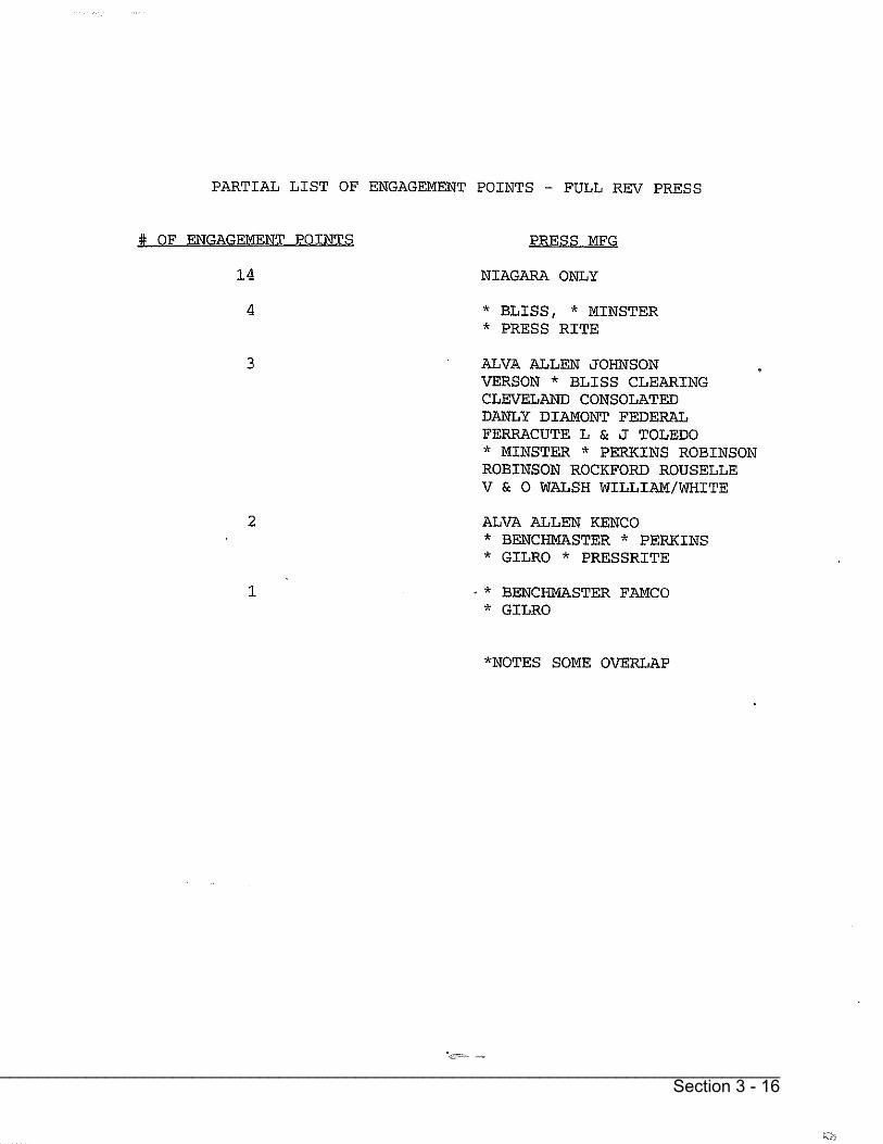
__________________________________________________________________________________________________________Section 3 - 16

__________________________________________________________________________________________________________Section 3 - 17

Section 3 - 18
1910.217(d)(3) -- Scrap handling. The employer shall provide means for handling scrap fromroll feed or random length stock operations. Scrap cutters used in conjunction with scraphandling systems shall be safeguarded in accordance with paragraph (c) of this section and with1910.219.
1910.217(d)(4) -- Guide post hazard. The hazard created by a guide post (when it is located inthe immediate vicinity of the operator) when separated from its bushing by more than one-fourthinch shall be considered as a point of operation hazard and be protected in accordance withparagraph (c) of this section.
1910.217(d)(5) -- Unitized tooling. If unitized tooling is used, the opening between the top ofthe punch holder and the face of the slide, or striking pad, shall be safeguarded in accordancewith the requirements of paragraph (c) of this section.
1910.217(d)(6) -- Tonnage, stroke, and weight designation. All dies shall be:
1910.217(d)(6)(i) -- Stamped with the tonnage and stroke requirements, or have thesecharacteristics recorded if these records are readily available to the die setter;
1910.217(d)(6)(ii) -- Stamped to indicate upper die weight when necessary for aircounterbalance pressure adjustment; and
1910.217(d)(6)(iii) -- Stamped to indicate complete die weight when handling equipment maybecome overloaded.
1910.217(d)(7) -- Die fastening. Provision shall be made in both the upper and lower shoes forsecurely mounting the die to the bolster and slide. Where clamp caps or setscrews are used inconjunction with punch stems, additional means of securing the upper shoe to the slide shall beused.
1910.217(d)(8) -- Die handling. Handling equipment attach points shall be provided on all diesrequiring mechanical handling.
1910.217(d)(9) -- Diesetting.
1910.217(d)(9)(i) -- The employer shall establish a diesetting procedure that will insurecompliance with paragraph (c) of this section.
1910.217(d)(9)(ii) -- The employer shall provide spring loaded turnover bars, for pressesdesigned to accept such turnover bars.
1910.217(d)(9)(iii) -- The employer shall provide die stops or other means to prevent losingcontrol of the die while setting or removing dies in presses which are inclined.

Section 3 - 19
1910.217(d)(9)(iv) -- The employer shall provide and enforce the use of safety blocks for usewhenever dies are being adjusted or repaired in the press.
1910.217(d)(9)(v) -- The employer shall provide brushes, swabs, lubricating rolls, andautomatic or manual pressure guns so that operators and diesetters shall not be required toreach into the point of operation or other hazard areas to lubricate material, punches or dies.
1910.217(e) -- Inspection, maintenance, and modification of presses -
1910.217(e)(1) -- Inspection and maintenance records.
1910.217(e)(1)(i) -- It shall be the responsibility of the employer to establish and follow aprogram of periodic and regular inspections of his power presses to ensure that all their parts,auxiliary equipment, and safeguards are in a safe operating condition and adjustment. Theemployer shall maintain a certification record of inspections which includes the date ofinspection, the signature of the person who performed the inspection and the serial number, orother identifier, of the power press that was inspected.
1910.217(e)(1)(ii) -- Each press shall be inspected and tested no less than weekly to determinethe condition of the clutch/brake mechanism, antirepeat feature and single stroke mechanism.Necessary maintenance or repair or both shall be performed and completed before the press isoperated. These requirements do not apply to those presses which comply with paragraphs (b)(13) and (14) of this section. The employer shall maintain a certification record of inspections,tests and maintenance work which includes the date of the inspection, test or maintenance; thesignature of the person who performed the inspection, test, or maintenance; and the serialnumber or other identifier of the press that was inspected, tested or maintained.
1910.217(e)(2) -- Modification. It shall be the responsibility of any person modifying a powerpress to furnish instructions with the modification to establish new or changed guidelines for useand care of the power press so modified.
1910.217(e)(3) -- Training of maintenance personnel. It shall be the responsibility of theemployer to insure the original and continuing competence of personnel caring for, inspecting,and maintaining power presses.
1910.217(f) -- Operation of power presses -
1910.217(f)(1) -- [Reserved]
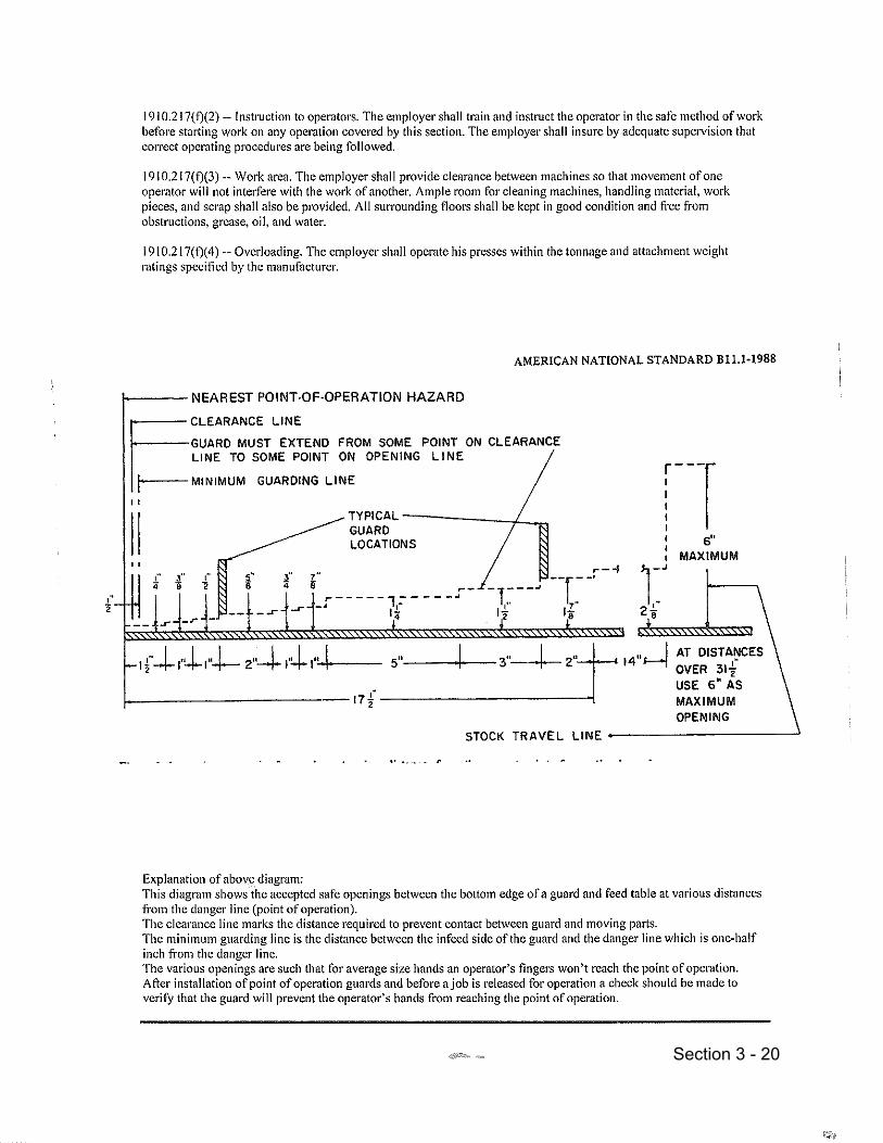
Section 3 - 20

Section 3 - 21
Table O-10 [In inches]
Distance of opening from point ofoperation hazard
Maximum width ofopening
1/2 to 1 1/2 1/41 1/2 to 2 1/2 3/82 1/2 to 3 1/2 1/23 1/2 to 5 1/2 5/85 1/2 to 6 1/2 3/46 1/2 to 7 1/2 7/87 1/2 to 12 1/2 1 1/412 1/2 to 15 1/2 1 1/215 1/2 to 17 1/2 1 7/817 1/2 to 31 1/2 2 1/8
This table shows the distances that guards shall be positioned from the danger line inaccordance with the required openings.
1910.217(g) -- Reports of injuries to employees operating mechanical power presses.
1910.217(g)(1) -- The employer shall, within 30 days of the occurrence, report to either theDirector of the Directorate of Safety Standards Programs, OSHA, U.S. Department of Labor,Washington, D.C. 20210, or the State agency administering a plan approved by the AssistantSecretary of Labor for Occupational Safety and Health, all point of operation injuries tooperators or other employees. The following information shall be included in the report:
1910.217(g)(1)(i) -- Employer's name, address and location of the workplace (establishment).
1910.217(g)(1)(ii) -- Employee's name, injury sustained, and the task being performed(operation, set-up, maintenance, or other).
1910.217(g)(1)(iii) -- Type of clutch used on the press (full revolution, part revolution, or directdrive).
1910.217(g)(1)(iv) -- Type of safeguard(s) being used (two hand control, two hand trip, pull-outs, sweeps, or other). If the safeguard is not described in this section, give a completedescription.
1910.217(g)(1)(v) -- Cause of the accident (repeat of press, safeguard failure, removing stuckpart or scrap, no safeguard provided, no safeguard in use, or other).

Section 3 - 22
1910.217(g)(1)(vi) -- Type of feeding (manual with hands in dies or with hands out of dies,semiautomatic, automatic, or other).
1910.217(g)(1)(vii) -- Means used to actuate press stroke (foot trip, foot control, hand trip,hand control, or other).
1910.217(g)(1)(viii) -- Number of operators required for the operation and the number ofoperators provided with controls and safeguards.
1910.217(h) -- Presence sensing device initiation (PSDI).
1910.217(h)(1) -- General
1910.217(h)(1)(i) -- The requirements of paragraph (h) shall apply to all part revolutionmechanical power presses used in the PSDI mode of operation.
1910.217(h)(1)(ii) -- The relevant requirements of paragraphs (a) through (g) of this sectionalso shall apply to all presses used in the PSDI mode of operation whether or not crossreferenced in this paragraph (h). Such cross- referencing of specific requirements fromparagraphs (a) through (g) of this section is intended only to enhance convenience andunderstanding in relating to the new provisions to the existing standard, and is not to beconstrued as limiting the applicability of other provisions in paragraphs (a) through (g) of thissection.
1910.217(h)(1)(iii) -- Full revolution mechanical power presses shall not be used in the PSDImode of operation.
1910.217(h)(1)(iv) -- Mechanical power presses with a configuration which would allow aperson to enter, pass through, and become clear of the sensing field into the hazardous portionof the press shall not be used in the PSDI mode of operation.
1910.217(h)(1)(v) -- The PSDI mode of operation shall be used only for normal productionoperations. Die-setting and maintenance procedures shall comply with paragraphs (a) through(g) of this section, and shall not be done in the PSDI mode.
1910.217(h)(2) -- Brake and clutch requirements.
1910.217(h)(2)(i) -- Presses with flexible steel band brakes or with mechanical linkageactuated brakes or clutches shall not be used in the PSDI mode.

Section 3 -23
1910.217(h)(2)(ii) -- Brake systems on presses used in the PSDI mode shall have sufficienttorque so that each average value of stopping times (Ts) for stops initiated at approximately 45degrees, 60 degrees, and 90 degrees, respectively, of crankshaft angular position, shall not bemore than 125 percent of the average value of the stopping time at the top crankshaft position.Compliance with this requirement shall be determined by using the heaviest upper die to be usedon the press, and operating at the fastest press speed if there is speed selection.
1910.217(h)(2)(iii) -- Where brake engagement and clutch release is effected by spring action,such springs(s) shall operate in compression on a rod or within a hole or tube, and shall be ofnon-interleaving design.
1910.217(h)(3) -- Pneumatic systems.
1910.217(h)(3)(i) -- Air valve and air pressure supply/control.
1910.217(h)(3)(i)(A) -- requirements of paragraphs (b)(7)(xiii), (b)(7)(xiv), (b)(10), (b)(12)and (c)(5)(iii) of this section apply to the pneumatic systems of machines used in the PSDImode.
1910.217(h)(3)(i)(B) -- The air supply for pneumatic clutch/brake control valves shallincorporate a filter, an air regulator, and, when necessary for proper operation, a lubricator.
1910.217(h)(3)(i)(C) -- The air pressure supply for clutch/brake valves on machines used inthe PSDI mode shall be regulated to pressures less than or equal to the air pressure used whenmaking the stop time measurements required by paragraph (h)(2)(ii) of this section.
1910.217(h)(3)(ii) -- Air counterbalance systems.
1910.217(h)(3)(ii)(A) -- Where presses that have slide counterbalance systems are used in thePSDI mode, the counterbalance system shall also meet the requirements of paragraph (b)(9) ofthis section.
1910.217(h)(3)(ii)(B) -- Counterbalances shall be adjusted in accordance with the pressmanufacturer's recommendations to assure correct counterbalancing of the slide attachment(upper die) weight for all operations performed on presses used in the PSDI mode. Theadjustments shall be made before performing the stopping time measurements required byparagraphs (h)(2)(ii), (h)(5)(iii), and (h)(9)(v) of this section.

Section 3 - 24
1910.217(h)(4) -- Flywheels and bearings. Presses whose designs incorporate f...(h)(4) Flywheels and bearings. Presses whose designs incorporate flywheels running onjournals on the crankshaft or back shaft, or bull gears running on journals mounted on thecrankshaft, shall be inspected, lubricated, and maintained as provided in paragraph (h)(10) ofthis section to reduce the possibility of unintended and uncontrolled press strokes caused bybearing seizure.
1910.217(h)(5) -- Brake monitoring.
1910.217(h)(5)(i) -- Presses operated in the PSDI mode shall be equipped with a brakemonitor that meets the requirements of paragraphs (b)(13) and (b)(14) of this section. Inaddition, the brake monitor shall be adjusted during installation certification to preventsuccessive stroking of the press if increases in stopping time cause an increase in the safetydistance above that required by paragraph (h)(9)(v) of this section.
1910.217(h)(5)(ii) -- Once the PSDI safety system has been certified/validated, adjustment ofthe brake monitor shall not be done without prior approval of the validation organization forboth the brake monitor adjustment and the corresponding adjustment of the safety distance. Thevalidation organization shall in its installation validation, state that in what circumstances, if any,the employer has advance approval for adjustment, when prior oral approval is appropriate andwhen prior approval must be in writing. The adjustment shall be done under the supervision ofan authorized person whose qualifications include knowledge of safety distance requirementsand experience with the brake system and its adjustment. When brake wear or other factorsextend press stopping time beyond the limit permitted by the brake monitor, adjustment, repair,or maintenance shall be performed on the brake or other press system element that extends thestopping time.
1910.217(h)(5)(iii) -- The brake monitor setting shall allow an increase of no more than 10percent of the longest stopping time for the press, or 10 milliseconds, whichever is longer,measured at the top of the stroke.
1910.217(h)(6) -- Cycle control and control systems.
1910.217(h)(6)(i) -- The control system on presses used in the PSDI mode shall meet theapplicable requirements of paragraphs (b)(7), (b)(8), (b)(13), and (c)(5) of this section.
1910.217(h)(6)(ii) -- The control system shall incorporate a means of dynamically monitoringfor decoupling of the rotary position indicating mechanism drive from the crankshaft. Thismonitor shall stop slide motion and prevent successive press strokes if decoupling occurs, or ifthe monitor itself fails.

Section 3 - 25
1910.217(h)(6)(iii) -- The mode selection means of paragraph (b)(1)(iii) of this section shallhave at least one position for selection of the PSDI mode. Where more than one interruption ofthe light sensing field is used in the initiation of a stroke, either the mode selection means musthave one position for each function, or a separate selection means shall be provided whichbecomes operable when the PSDI mode is selected. Selection of PSDI mode and the numberof interruptions/withdrawals of the light sensing field required to initiate a press cycle shall be bymeans capable of supervision by the employer.
1910.217(h)(6)(iv) -- A PSDI set-up/reset means shall be provided which requires an overtaction by the operator, in addition to PSDI mode selection, before operation of the press bymeans of PSDI can be started.
1910.217(h)(6)(v) -- An indicator visible to the operator and readily seen by the employer shallbe provided which shall clearly indicate that the system is set-up for cycling in the PSDI mode.
1910.217(h)(6)(vi) -- The control system shall incorporate a timer to deactivate PSDI whenthe press does not stroke within the period of time set by the timer. The timer shall be manuallyadjustable, to a maximum time of 30 seconds. For any timer setting greater than 15 seconds, theadjustment shall be made by the use of a special tool available only to authorized persons.Following a deactivation of PSDI by the timer, the system shall make it necessary to reset theset-up/reset means in order to reactivate the PSDI mode.
1910.217(h)(6)(vii) -- Reactivation of PSDI operation following deactivation of the PSDImode from any other cause, such as activation of the red color stop control required byparagraph (b)(7)(ii) of this section, interruption of the presence sensing field, opening of aninterlock, or reselection of the number of sensing field interruptions/withdrawals required tocycle the press, shall require resetting of the set-up/reset means.
1910.217(h)(6)(viii) -- The control system shall incorporate an automatic means to preventinitiation or continued operation in the PSDI mode unless the press drive motor is energized inthe forward direction of crankshaft rotation.
1910.217(h)(6)(ix) -- The control design shall preclude any movement of the slide caused byoperation of power on, power off, or selector switches, or from checks for proper operationsas required by paragraph (h)(6)(xiv) of this section.
1910.217(h)(6)(x) -- All components and subsystems of the control system shall be designedto operate together to provide total control system compliance with the requirements of thissection.

Section 3 - 26
1910.217(h)(6)(xi) -- Where there is more than one operator of a press used for PSDI, eachoperator shall be protected by a separate, independently functioning, presence sensing device.The control system shall require that each sensing field be interrupted the selected number oftimes prior to initiating a stroke. Further, each operator shall be provided with a set-up/resetmeans that meets the requirements of paragraph (h)(6) of this section, and which must beactuated to initiate operation of the press in the PSDI mode.
1910.217(h)(6)(xii) -- [Reserved]
1910.217(h)(6)(xiii) -- The Control system shall incorporate interlocks for supplementalguards, if used, which will prevent stroke initiation or will stop a stroke in progress if anysupplemental guard fails or is deactivated.
1910.217(h)(6)(xiv) -- The control system shall perform checks for proper operation of allcycle control logic element switches and contacts at least once each cycle. Control elementsshall be checked for correct status after power "on" and before the initial PSDI stroke.
1910.217(h)(6)(xv) -- The control system shall have provisions for an "inch" operating meansmeeting the requirements of paragraph (b)(7)(iv) of this section. Die-setting shall not be done inthe PSDI mode. Production shall not be done in the "inch" mode.
1910.217(h)(6)(xvi) -- The control system shall permit only a single stroke per initiationcommand.
1910.217(h)(6)(xvii) -- Controls with internally stored programs (e.g., mechanical, electro-mechanical, or electronic) shall meet the requirements of paragraph (b)(13) of this section, andshall default to a predetermined safe condition in the event of any single failure within the system.Programmable controllers which meet the requirements for controls with internally storedprograms stated above shall be permitted only if all logic elements affecting the safety systemand point of operation safety are internally stored and protected in such a manner that theycannot be altered or manipulated by the user to an unsafe condition.
1910.217(h)(7) -- Environmental requirements. Control components shall be selected,constructed, and connected together in such a way as to withstand expected operational andenvironmental stresses, at least including those outlined in Appendix A. Such stresses shall notso affect the control system as to cause unsafe operation.

Section 3 - 27
1910.217(h)(8) -- Safety system.
1910.217(h)(8)(i) -- Mechanical power presses used in the PSDI mode shall be operatedunder the control of a safety system which, in addition to meeting the applicable requirements ofparagraphs (b)(13) and (c)(5) and other applicable provisions of this section, shall function suchthat a single failure or single operating error shall not cause injury to personnel from point ofoperation hazards.
1910.217(h)(8)(ii) -- The safety system shall be designed, constructed, and arranged as anintegral total system, including all elements of the press, the controls, the safeguarding and anyrequired supplemental safeguarding, and their interfaces with the operator and that part of theenvironment which has effect on the protection against point of operation hazards.
1910.217(h)(9) -- Safeguarding the point of operation.
1910.217(h)(9)(i) -- The point of operation of presses operated in the PSDI mode shall besafeguarded in accordance with the requirements of paragraph (c) of this section, except thatthe safety distance requirements of paragraph (h)(9)(v) of this section shall be used for PSDIoperation.
1910.217(h)(9)(ii) --
1910.217(h)(9)(ii)(A) -- PSDI shall be implemented only by use of light curtain (photo-electric) presence sensing devices which meet the requirements of paragraph (c)(3)(iii)(c) of thissection unless the requirements of the following paragraph have been met.
1910.217(h)(9)(ii)(B) -- Alternatives to photo-electric light curtains may be used for PSDIwhen the employer can demonstrate, through tests and analysis by the employer or themanufacturer, that the alternative is as safe as the photo-electric light curtain, that the alternativemeets the conditions of this section, has the same long term reliability as light curtains and can beintegrated into the entire safety system as provided for in this section. Prior to use, both theemployer and manufacturer must certify that these requirements and all the other applicablerequirements of this section are met and these certifications must be validated by an OSHA-recognized third-party validation organization to meet these additional requirements and all theother applicable requirements of paragraphs (a) through (h) and Appendix A of this section.Three months prior to the operation of any alternative system, the employer must notify theOSHA Directorate of Safety Standards programs of the name of the system to be installed, themanufacturer and the OSHA-recognized third-party validation organization immediately. Uponrequest, the employer must make available to that office all tests and analyses for OSHAreview.
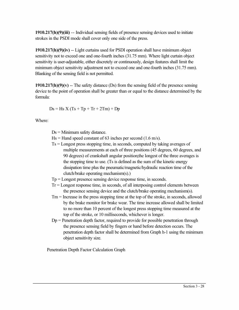
Section 3 - 28
1910.217(h)(9)(iii) -- Individual sensing fields of presence sensing devices used to initiatestrokes in the PSDI mode shall cover only one side of the press.
1910.217(h)(9)(iv) -- Light curtains used for PSDI operation shall have minimum objectsensitivity not to exceed one and one-fourth inches (31.75 mm). Where light curtain objectsensitivity is user-adjustable, either discretely or continuously, design features shall limit theminimum object sensitivity adjustment not to exceed one and one-fourth inches (31.75 mm).Blanking of the sensing field is not permitted.
1910.217(h)(9)(v) -- The safety distance (Ds) from the sensing field of the presence sensingdevice to the point of operation shall be greater than or equal to the distance determined by theformula:
Ds = Hs X (Ts + Tp + Tr + 2Tm) + Dp
Where:
Ds = Minimum safety distance. Hs = Hand speed constant of 63 inches per second (1.6 m/s). Ts = Longest press stopping time, in seconds, computed by taking averages of
multiple measurements at each of three positions (45 degrees, 60 degrees, and90 degrees) of crankshaft angular position;the longest of the three averages isthe stopping time to use. (Ts is defined as the sum of the kinetic energydissipation time plus the pneumatic/magnetic/hydraulic reaction time of theclutch/brake operating mechanism(s).)
Tp = Longest presence sensing device response time, in seconds. Tr = Longest response time, in seconds, of all interposing control elements between
the presence sensing device and the clutch/brake operating mechanism(s). Tm = Increase in the press stopping time at the top of the stroke, in seconds, allowed
by the brake monitor for brake wear. The time increase allowed shall be limitedto no more than 10 percent of the longest press stopping time measured at thetop of the stroke, or 10 milliseconds, whichever is longer.
Dp = Penetration depth factor, required to provide for possible penetration throughthe presence sensing field by fingers or hand before detection occurs. Thepenetration depth factor shall be determined from Graph h-1 using the minimumobject sensitivity size.
Penetration Depth Factor Calculation Graph

Section 3 - 29
1910.217(h)(9)(vi) -- The presence sensing device location shall either be set at each toolchange and set-up to provide at least the minimum safety distance, or fixed in location toprovide a safety distance greater than or equal to the minimum safety distance for all tooling set-ups which are to be used on that press.
1910.217(h)(9)(vii) -- Where presence sensing device location is adjustable, adjustment shallrequire the use of a special tool available only to authorized persons.
1910.217(h)(9)(viii) -- Supplemental safeguarding shall be used to protect all areas of accessto the point of operation which are unprotected by the PSDI presence sensing device. Suchsupplemental safeguarding shall consist of either additional light curtain (photo-electric) presencesensing devices or other types of guards which meet the requirements of paragraphs (c) and (h)of this section.
1910.217(h)(9)(viii)(A) -- Presence sensing devices used as supplemental safeguarding shallnot initiate a press stroke, and shall conform to the requirements of paragraph (c)(3)(iii) andother applicable provisions of this section, except that the safety distance shall comply withparagraph (h)(9)(v) of this section.
1910.217(h)(9)(viii)(B) -- Guards used as supplemental safeguarding shall conform to thedesign, construction and application requirements of paragraph (c)(2) of this section, and shallbe interlocked with the press control to prevent press PSDI operation if the guard fails, isremoved, or is out of position.
1910.217(h)(9)(ix) -- Barriers shall be fixed to the press frame or bolster to prevent personnelfrom passing completely through the sensing field, where safety distance or press configuration issuch that personnel could pass through the PSDI presence sensing field and assume a positionwhere the point of operation could be accessed without detection by the PSDI presence sensingdevice. As an alternative, supplemental presence sensing devices used only in the safeguardmode may be provided. If used, these devices shall be located so as to detect all operatorlocations and positions not detected by the PSDI sensing field, and shall prevent stroking orstop a stroke in process when any supplemental sensing field(s) are interrupted.
1910.217(h)(9)(x) -- Hand tools. Where tools are used for feeding, removal of scrap,lubrication of parts, or removal of parts that stick on the die in PSDI operations:
1910.217(h)(9)(x)(A) -- The minimum diameter of the tool handle extension shall be greaterthan the minimum object sensitivity of the presence sensing device(s) used to initiate pressstrokes; or
1910.217(h)(9)(x)(B) -- The length of the hand tool shall be such as to ensure that theoperator's hand will be detected for any safety distance required by the press set-ups.

Section 3 - 30
1910.217(h)(10) -- Inspection and maintenance.
1910.217(h)(10)(i) -- Any press equipped with presence sensing devices for use in PSDI, orfor supplemental safeguarding on presses used in the PSDI mode, shall be equipped with a testrod of diameter specified by the presence sensing device manufacturer to represent the minimumobject sensitivity of the sensing field. Instructions for use of the test rod shall be noted on a labelaffixed to the presence sensing device.
1910.217(h)(10)(ii) -- The following checks shall be made at the beginning of each ...(h)(10)(ii) The following checks shall be made at the beginning of each shift and whenevera die change is made.
1910.217(h)(10)(ii)(A) -- A check shall be performed using the test rod according to thepresence sensing device manufacturer's instructions to determine that the presence sensingdevice used for PSDI is operational.
1910.217(h)(10)(ii)(B) -- The safety distance shall be checked for compliance with (h)(9)(v) ofthis section.
1910.217(h)(10)(ii)(C) -- A check shall be made to determine that all supplementalsafeguarding is in place. Where presence sensing devices are used for supplementalsafeguarding, a check for proper operation shall be performed using the test rod according tothe presence sensing device manufacturer's instructions.
1910.217(h)(10)(ii)(D) -- A check shall be made to assure that the barriers and/orsupplemental presence sensing devices required by paragraph (h)(9)(ix) of this section areoperating properly.
1910.217(h)(10)(ii)(E) -- A system or visual check shall be made to verify correctcounterbalance adjustment for die weight according to the press manufacturer's instructions,when a press is equipped with a slide counterbalance system.
1910.217(h)(10)(iii) -- When presses used in the PSDI mode have flywheel or bullgear runningon crankshaft mounted journals and bearings, or a flywheel mounted on back shaft journals andbearings, periodic inspections following the press manufacturer's recommendations shall bemade to ascertain that bearings are in good working order, and that automatic lubricationsystems for these bearings (if automatic lubrication is provided) are supplying proper lubrication.On presses with provision for manual lubrication of flywheel or bullgear bearings, lubricationshall be provided according to the press manufacturer's recommendations.

Section 3 - 31
1910.217(h)(10)(iv) -- Periodic inspections of clutch and brake mechanisms shall beperformed to assure they are in proper operating condition. The press manufacturer'srecommendations shall be followed.
1910.217(h)(10)(v) -- When any check of the press, including those performed in accordancewith the requirements of paragraphs (h)(10)(ii), (iii) or (iv) of this section, reveals a condition ofnoncompliance, improper adjustment, or failure, the press shall not be operated until thecondition has been corrected by adjustment, replacement, or repair.
1910.217(h)(10)(vi) -- It shall be the responsibility of the employer to ensure the competenceof personnel caring for, inspecting, and maintaining power presses equipped for PSDIoperation, through initial and periodic training.
1910.217(h)(11) -- Safety system certification/validation.
1910.217(h)(11)(i) -- Prior to the initial use of any mechanical press in the PSDI mode, twosets of certification and validation are required:
1910.217(h)(11)(i)(A) -- The design of the safety system required for the use of a press in thePSDI mode shall be certified and validated prior to installation. The manufacturer's certificationshall be validated by an OSHA- recognized third-party validation organization to meet allapplicable requirements of paragraphs (a) through (h) and Appendix A of this section.
1910.217(h)(11)(i)(B) -- Alter a press has been equipped with a safety system whose designhas been certified and validated in accordance with paragraph (h)(11)(i) of this section, thesafety system installation shall be certified by the employer, and then shall be validated by anOSHA-recognized third-party validation organization to meet all applicable requirements ofparagraphs (a) through (h) and Appendix A of this section.
1910.217(h)(11)(ii) -- At least annually thereafter, the safety system on a mechanical powerpress used in the PSDI mode shall be recertified by the employer and revalidated by an OSHA-recognized third-party validation organization to meet all applicable requirements of paragraphs(a) through (h) and Appendix A of this section. Any press whose safety system has not beenrecertified and revalidated within the preceding 12 months shall be removed from service in thePSDI mode until the safety system is recertified and revalidated.

Section 3 - 32
1910.217(h)(11)(iii) -- A label shall be affixed to the press as part of each installationcertification/validation and the most recent recertification/revalidation. The label shall indicate thepress serial number, the minimum safety distance (Ds) required by paragraph (h)(9)(v) of thissection, the fulfillment of design certification/validation, the employer's signed certification, theidentification of the OSHA-recognized third-party validation organization, its signed validation,and the date the certification/validation and recertification/revalidation are issued.
1910.217(h)(11)(iv) -- Records of the installation certification and validation and the mostrecent recertification and revalidation shall be maintained for each safety system equipped pressby the employer as long as the press is in use. The records shall include the manufacture andmodel number of each component and subsystem, the calculations of the safety distance asrequired by paragraph (h)(9)(v) of this section, and the stopping time measurements required byparagraph (h)(2)(ii) of this section. The most recent records shall be made available to OSHAupon request.
1910.217(h)(11)(v) -- The employer shall notify the OSHA-recognized third-party validationorganization within five days whenever a component or a subsystem of the safety system fails ormodifications are made which may affect the safety of the system. The failure of a criticalcomponent shall necessitate the removal of the safety system from service until it is recertifiedand revalidated, except recertification by the employer without revalidation is permitted when anon-critical component or subsystem is replaced by one of the same manufacture and design asthe original, or determined by the third-party validation organization to be equivalent bysimilarity analysis, as set forth in Appendix A.
1910.217(h)(11)(vi) -- The employer shall notify the OSHA-recognized third-party validationorganization within five days of the occurrence of any point of operation injury while a press isused in the PSDI mode. This is in addition to the report of injury required by paragraph (g) ofthis section; however, a copy of that report may be used for this purpose.
1910.217(h)(12) -- Die setting and work set-up.
1910.217(h)(12)(i) -- Die setting on presses used in the PSDI mode shall be performed inaccordance with paragraphs (d) and (h) of this section.
1910.217(h)(12)(ii) -- The PSDI mode shall not be used for die setting or set-up. Analternative manual cycle initiation and control means shall be supplied for use in die setting whichmeets the requirements of paragraph (b)(7) of this section.

Section 3 - 33
1910.217(h)(12)(iii) -- Following a die change, the safety distance, the proper application ofsupplemental safeguarding, and the slide counterbalance adjustment (if the press is equippedwith a counterbalance) shall be checked and maintained by authorized persons whosequalifications include knowledge of the safety distance, supplemental safe-guardingrequirements, and the manufacturer's specifications for counterbalance adjustment. Adjustmentof the location of the PSDI presence sensing device shall require use of a special tool availableonly to the authorized persons.
1910.217(h)(13) -- Operator training.
1910.217(h)(13)(i) -- The operator training required by paragraph (f)(2) of this section shall beprovided to the employee before the employee initially operates the press and as needed tomaintain competence, but not less than annually thereafter. It shall include instruction relative tothe following items for presses used in the PSDI mode.
1910.217(h)(13)(i)(A) -- The manufacturer's recommended test procedures for checkingoperation of the presence sensing device. This shall include the use of the test rod required byparagraph (h)(10)(i) of this section.
1910.217(h)(13)(i)(B) -- The safety distance required.
1910.217(h)(13)(i)(C) -- The operation, function and performance of the PSDI mode.
1910.217(h)(13)(i)(D) -- The requirements for hand tools that may be used in the PSDI mode.
1910.217(h)(13)(i)(E) -- The severe consequences that can result if he or she attempts tocircumvent or by-pass any of the safe-guard or operating functions of the PSDI system.
1910.217(h)(13)(ii) -- The employer shall certify that employees have been trained bypreparing a certification record which includes the identity of the person trained, the signature ofthe employer or the person who conducted the training, and the date the training wascompleted. The certification record shall be prepared at the completion of training and shall bemaintained on file for the duration of the employee's employment. The certification record shallbe made available upon request to the Assistant Secretary for Occupational Safety and Health.[39 FR 32502, June 27, 1974. as amended at 39 FR 41846, Dec. 23, 1974; 40 FR 3982,Jan. 27, 1975; 43 FR 49750, Oct. 24, 1978; 45 FR 8594, Feb. 8. 1980; 49 FR 18295, Apr.30, 1984; 51 FR 34561, Sept. 29, 1986; 53 FR 8353, Mar. 14, 1988; 54 FR 24333, June 7,1989; 61 FR 5507, Feb. 13, 1996; 61 FR 9227, March 7, 1996]

Section 3 - 34
1910.217 App A Mandatory requirements for certification/validation of safety systems forpresence sensing deviceinitiation of mechanical power presses
Subpart O
SubPart Title Machinery and Machine Guarding
PurposeThe purpose of the certification/validation of safety systems for presence sensing device initiation(PSDI) of mechanical power presses is to ensure that the safety systems are designed, installed,and maintained in accordance with all applicable requirements of 29 CFR 1910.217 (a) through(h) and this Appendix A.
GeneralThe certification/validation process shall utilize an independent third-party validation organizationrecognized by OSHA in accordance with the requirements specified in Appendix C of thissection.
While the employer is responsible for assuring that the certification/validation requirements In1910.217(h)(11) are fulfilled, the design certification of PSDI safety systems may be initiated bymanufacturers, employers, and/or their representatives. The term "manufacturers" refers to themanufacturer of any of the components of the safety system. An employer who assembles aPSDI safety system would be a manufacturer as well as employer for purposes of this standardand Appendix.
The certification/validation process includes two stages. For design certification, in the firststage, the manufacturer (which can be an employer) certifies that the PSDI safety system meetsthe requirements of 29 CFR 1910.217 (a) through (h) and this Appendix A, based onappropriate design criteria and tests. In the second stage. the OSHA-recognized third-partyvalidation organization validates that the PSDI safety system meets the requirements of 29 CFR1910.217 (a) through (h) and this Appendix A and the manufacturer's certification by reviewingthe manufacturer's design and test data and performing any additional reviews required by thisstandard or which it believes appropriate.

Section 3 - 35
For installation certification/validation and annual recertification/revalidation, in the first stage theemployer certifies or recertifies that the employer is installing or utilizing a PSDI safety systemvalidated as meeting the design requirements of 29 CFR 1910.217 (a) through (h) and thisAppendix A by an OSHA-recognized third-party validation organization and that theinstallation, operation and maintenance meet the requirements of 29 CFR 1910.217 (a) through(h) and this Appendix A. In the second stage. the OSHA-recognized third-party validationorganization validates or revalidates that the PSDI safety system installation meets therequirements of 29 CFR 1910.217 (a) through (h) and this Appendix A and the employer'scertification, by reviewing that the PSDI safety system has been certified; the employer'scertification, designs and tests, if any; the installation, operation, maintenance and training; andby performing any additional tests and reviews which the validation organization believes isnecessary.
SummaryThe certification/validation of safety systems for PSDI shall consider the press, controls,safeguards, operator, and environment as an integrated system which shall comply with all of therequirements in 29 CFR 1910.217 (a) through (h) and this Appendix A. Thecertification/validation process shall verify that the safety system complies with the OSHA safetyrequirements as follows:
A. Design Certification/Validation1. The major parts, components and subsystems used shall be defined by part number or serialnumber, as appropriate, and by manufacturer to establish the configuration of the system.2. The identified parts, components and subsystems shall be certified by the manufacturer to beable to withstand the functional and operational environments of the PSDI safety system.3. The total system design shall be certified by the manufacturer as complying with allrequirements in 29 CFR 1910.217 (a) through (h) and this Appendix A.4. The third-party validation organization shall validate the manufacturer's certification underparagraphs 2 and 3.
B. Installation Certification/Validation1. The employer shall certify that the PSDI safety system has been design certified andvalidated, that the installation meets the operational and environmental requirements specified bythe manufacturer, that the installation drawings are accurate, and that the installation meets therequirements of 29 CFR 1910.217 (a) through (h) and this Appendix A. (The operational andinstallation requirements of the PSDI safety system may vary for different applications.)2. The third-party validation organization shall validate the employer's certifications that thePSDI safety system is design certified and validated, that the installation meets the installationand environmental requirements specified by the manufacturer, and that the installation meets therequirements of 29 CFR 1910.217 (a) through (h) and this Appendix A.
C. Recertification/Revalidation

Section 3 - 36
1. The PSDI safety system shall remain under certification/validation for the shorter of one yearor until the system hardware is changed, modified or refurbished, or operating conditions arechanged (including environmental, application or facility changes), or a failure of a criticalcomponent has occurred.2. Annually, or after a change specified in paragraph 1., the employer shall inspect and recertifythe installation as meeting the requirements set forth under B., InstallationCertification/Validation.3. The third-party validation organization, annually or after a change specified in paragraph 1.,shall validate the employer's certification that the requirements of paragraph B., InstallationCertification/Validation have been met.(NOTE: Such changes in operational conditions as die changes or press relocations notinvolving disassembly or revision to the safety system would not requirerecertification/revalidation.)
Certification/Validation RequirementsA. General Design Certification/Validation Requirements1. Certification/Validation Program Requirements. The manufacturer shall certify and theOSHA-recognized third-party validation organization shall validate that:(a) The design of components, subsystems, software and assemblies meets OSHA performancerequirements and are ready for the intended use; and(b) The performance of combined subsystems meets OSHA's operational requirements.2. Certification/Validation Program Level of Risk Evaluation Requirements. The manufacturershall evaluate and certify, and the OSHA-recognized third-party validation organization shallvalidate, the design and operation of the safety system by determining conformance with thefollowing:a. The safety system shall have the ability to sustain a single failure or a single operating errorand not cause injury to personnel from point of operation hazards. Acceptable design featuresshall demonstrate, in the following order or precedence, that:(1) No single failure points may cause injury; or(2) Redundancy, and comparison and/or diagnostic checking, exist for the critical items that maycause injury, and the electrical, electronic, electromechanical and mechanical parts andcomponents are selected so that they can withstand operational and external environments. Thesafety factor and/or derated percentage shall be specifically noted and complied with.

Section 3 - 37
b. The manufacturer shall design, evaluate, test and certify, and the third-party validationorganization shall evaluate and validate, that the PSDI safety system meets appropriaterequirements in the following areas.(1) Environmental Limits:(a) Temperature(b) Relative humidity(c) Vibration(d) Fluid compatibility with other materials(2) Design Limits(a) Power requirements(b) Power transient tolerances(c) Compatibility of materials used(d) Material stress tolerances and limits(e) Stability to long term power fluctuations(f) Sensitivity to signal acquisition(g) Repeatability of measured parameter without inadvertent initiation of a press stroke(h) Operational life of components in cycles, hours, or both(i) Electromagnetic tolerance to:(1) Specific operational wave lengths; and(2) Externally generated wave lengths(3) New Design Certification/Validation. Design certification/validation for a new safety system,i.e., a new design or new integration of specifically identified components and subsystems,would entail a single certification/validation which would be applicable to all identical safetysystems. It would not be necessary to repeat the tests on individual safety systems of the samemanufacture or design. Nor would it be necessary to repeat these tests in the case ofmodifications where determined by the manufacturer and validated by the third- party validationorganization to be equivalent by similarity analysis. Minor modifications not affecting the safetyof the system may be made by the manufacturer without revalidation.Substantial modifications would require testing as a new safety system, as deemed necessary bythe validation organization.

Section 3 - 38
B. Additional Detailed Design Certification/Validation Requirements1. General. The manufacturer or the manufacturer's representative shall certify to and submit toan OSHA-recognized third-party validation organization the documentation necessary todemonstrate that the PSDI safety system design is in full compliance with the requirements of 29CFR 1910.217(a)-(h) and this Appendix A, as applicable, by means of analysis, tests, orcombination of both, establishing that the following additional certification/validationrequirements are fulfilled.2. Reaction Times. For the purpose of demonstrating compliance with the reaction time requiredby 1910.217(h), the tests shall use the following definitions and requirements:a. "Reaction time" means the time, in seconds, it takes the signal, required to activate/deactivatethe system, to travel through the system, measured from the time of signal initiation to the timethe function being measured is completed.b. "Full stop" or "No movement of the slide or ram" means when the crankshaft rotation hasslowed to two or less revolutions per minute, just before stopping completely.c. "Function completion" means for, electrical, electromechanical and electronic devices, whenthe circuit produces a change of state in the output element of the device.d. When the change of state is motion, the measurement shall be made at the completion of themotion.e. The generation of the test signal introduced into the system for measuring reaction time shallbe such that the Initiation time can be established with an error of less than 0.5 percent of thereaction time measured.f. The instrument used to measure reaction time shall be calibrated to be accurate to within0.001 second.3. Compliance with 1910.21 7(h)(2)(ii). For compliance with these requirements, the averagevalue of the stopping time, Ts, shall be the arithmetic mean of at least 25 stops for each stopangle initiation measured with the brake and/or clutch unused, 50 percent worn, and 90 percentworn. The recommendations of the brake system manufacturer shall be used to simulate orestimate the brake wear. The manufacturer's recommended minimum lining depth shall beidentified and documented, and an evaluation made that the minimum depth will not beexceeded before the next (annual) recertification/revalidation. A correlation of the brake and/orclutch degradation based on the above tests and/or estimates shall be made and documented.The results shall document the conditions under which the brake and/or clutch will and will notcomply with the requirement. Based upon this determination, a scale shall be developed toindicate the allowable 10 percent of the stopping time at the top of the stroke for slide or ramovertravel due to brake wear. The scale shall be marked to indicate that brake adjustmentand/or replacement is required. The explanation and use of the scale shall be documented.The test specification and procedure shall be submitted to the validation organization for reviewand validation prior to the test. The validation organization representative shall witness at leastone set of tests.

Section 3 - 39
4. Compliance with 1910.217(h)(5)(iii) and (h)(9)(v). Each reaction time required to calculatethe Safety Distance, including the brake monitor setting, shall be documented in separatereaction time tests. These tests shall specify the acceptable tolerance band sufficient to assurethat tolerance build-up will not render the safety distances unsafe.a. Integrated test of the press fully equipped to operate in the PSDI mode shall be conductedto establish the total system reaction time.b. Brakes which are the adjustable type shall be adjusted properly before the test.5. Compliance with 1910.21 7(h)(2)(iii).a. Prior to conducting the brake system test required by paragraph (h)(2)(ii), a visual check shallbe made of the springs. The visual check shall include a determination that the spring housing orrod does not show damage sufficient to degrade the structural integrity of the unit, and the springdoes not show any tendency to interleave.b. Any detected broken or unserviceable springs shall be replaced before the test is conducted.The test shall be considered successful If the stopping time remains within that which isdetermined by paragraph (h)(9)(v) for the safety distance setting. If the increase in pressstopping time exceeds the brake monitor setting limit defined in paragraph (h)(5)(iii), the testshall be considered unsuccessful, and the cause of the excessive stopping time shall beinvestigated. It shall be ascertained that the springs have not been broken and that they arefunctioning properly.6. Compliance with 1910.21 7(h)(7).a. Tests which are conducted by the manufacturers of electrical components to establish stress,life, temperature and loading limits must be tests which are in compliance with the provisions ofthe National Electrical Code.b. Electrical and/or electronic cards or boards assembled with discreet components shall beconsidered a subsystem and shall require separate testing that the subsystems do not degrade inany of the following conditions:(1) Ambient temperature variation from -20 deg. C to +50 deg. C.(2) Ambient relative humidity of 99 percent.(3) Vibration of 45G for one millisecond per stroke when the item is to be mounted on the pressframe.(4) Electromagnetic interference at the same wavelengths used for the radiation sensing field, atthe power line frequency fundamental and harmonics, and also from outogenous radiation due tosystem switching.(5) Electrical power supply variations of + or - 15 percent.c. The manufacturer shall specify the test requirements and procedures from existing consensustests in compliance with the provisions of the National Electrical Code.d. Tests designed by the manufacturer shall be made available upon request to the validationorganization. The validation organization representative shall witness at least one set of each ofthese tests.

Section 3 - 40
7. Compliance with 1910.21 7(h)(9)(iv).a. The manufacturer shall design a test to demonstrate that the prescribed minimum objectsensitivity of the presence sensing device is met.b. The test specifications and procedures shall be made available upon request to the validationorganization.8. Compliance with 1910.217(h)(9)(x).a. The manufacturer shall design a test(s) to establish the hand tool extension diameters allowedfor variations in minimum object sensitivity response.b. The test(s) shall document the range of object diameter sizes which will produce both singleand double break conditions.c The test(s) specifications and procedures shall be made available upon request to thevalidation organization.9. Integrated Tests Certification/Validationa. The manufacturer shall design a set of integrated tests to demonstrate compliance with thefollowing requirements:Sections 1910.217(h)(6) (ii); (iii); (iv); (v); (vi); (vii); (viii); (ix); (xi); (xii); (xiii); (xiv); (xv); and(xvii).b. The integrated test specifications and procedures shall be made available to the validationorganization.10. Analysis.a. The manufacturer shall submit to the validation organization the technical analysis such asHazard Analysis, Failure Mode and Effect Analysis, Stress Analysis, Component and MaterialSelection Analysis, Fluid Compatibility, and/or other analyses which may be necessary todemonstrate, compliance with the following requirements:Sections 1910.217(h)(8) (i) and (ii); (h)(2)(ii) and (iii); (h)(3)(i) (A) and (C), and (ii); (h)(5) (i),(ii) and (iii); (h)(6) (i), (iii), (iv), (vi), (vii), (viii), (ix), (x), (xi), (xiii), (xiv), (xv), (xvi), and (xvii);(h)(7) (i) and (ii); (h)(9) (iv), (v), (viii), (ix) and (x); (h)(10) (i) and (ii).11. Types of Tests Acceptable for Certification/Validation.a. Test results obtained from development testing may be used to certify/validate the design.b. The test results shall provide the engineering data necessary to establish confidence that thehardware and software will meet specifications, the manufacturing process has adequate qualitycontrol and the data acquired was used to establish processes, procedures, and test levelssupporting subsequent hardware design, production, installation and maintenance.12. Validation for Design Certification/Validation. If, after review of all documentation, tests,analyses, manufacturer's certifications, and any additional tests which the third-party validationorganization believes are necessary, the third-party validation organization determines that thePSDI safety system is in full compliance with the applicable requirements of 29 CFR1910.217(a) through (h) and this Appendix A, it shall validate the manufacturer's certificationthat it so meets the stated requirements.

Section 3 - 41
C. Installation Certification/Validation Requirements1. The employer shall evaluate and test the PSDI system installation, shall submit to the OSHA-recognized third-party validation organization the necessary supporting documentation, and shallcertify that the requirements of 1910.217(a) through (h) and this Appendix A have been metand that the installation is proper.2. The OSHA-recognized third-party validation organization shall conduct tests, and/or reviewand evaluate the employer's installation tests, documentation and representations. If it sodetermines, it shall validate the employer's certification that the PSDI safety system is in fullconformance with all requirements of 29 CFR 1910.217(a) through (h) and this Appendix A.
D. Recertification/Revalidation Requirements1. A PSDI safety system which has received installation certification/validation shall undergorecertification/revalidation the earlier of:a. Each time the systems hardware is significantly changed, modified, or refurbished;b. Each time the operational conditions are significantly changed (including environmental,application or facility changes, but excluding such changes as die changes or press relocationsnot involving revision to the safety system);c. When a failure of a significant component has occurred or a change has been made whichmay affect safety; ord. When one year has elapsed since the installation certification/validation or the lastrecertification/revalidation.2. Conduct or recertification/revalidation. The employer shall evaluate and test the PSDI safetysystem installation, shall submit to the OSHA-recognized third-party validation organization thenecessary supporting documentation, and shall recertify that the requirements of 1910.217(a)through (h) and this Appendix are being met. The documentation shall include, but not be limitedto, the following items:a. Demonstration of a thorough inspection of the entire press and PSDI safety system toascertain that the installation, components and safeguarding have not been changed, modified ortampered with since the installation certification/validation or last recertification/revalidation wasmade.b. Demonstrations that such adjustments as may be needed (such as to the brake monitorsetting) have been accomplished with proper changes made in the records and on such noticesas are located on the press and safety system.c. Demonstration that review has been made of the reports covering the designcertification/validation, the installation certification/validation, and all recertification/revalidations,in order to detect any degradation to an unsafe condition, and that necessary changes have beenmade to restore the safety system to previous certification/validation levels.3. The OSHA-recognized third-party validation organization shall conduct tests, and/or reviewand evaluate the employer's installation, tests, documentation and representations. If It sodetermines, It shall revalidate the employer's recertification that the PSDI system is in fullconformance with all requirements of 29 CFR 1910.217(a) through (h) and this Appendix A.[53 FR 8358, Mar. 14, 1988]

Section 3 - 42
1910.217 App B Title Nonmandatory guidelines for certification/validation of safety systems forpresence sensing deviceinitiation of mechanical power presses
Subpart O
SubPart Title Machinery and Machine Guarding
ObjectivesThis Appendix provides employers, manufacturers, and their representatives, withnonmandatory guidelines for use in developing certification documents. Employers andmanufacturers are encouraged to recommend other approaches if there is a potential forimproving safety and reducing cost. The guidelines apply to certification/validation activity fromdesign evaluation through the completion of the installation test and the annualrecertification/revalidation tests.
General GuidelinesA. The certification/validation process should confirm that hazards identified by hazard analysis,(HA), failure mode effect analysis (FMEA), and other system analyses have been eliminated bydesign or reduced to an acceptable level through the use of appropriate design features, safetydevices, warning devices, or special procedures. The certification/validation process should alsoconfirm that residual hazards identified by operational analysis are addressed by warning,labeling safety instructions or other appropriate means.B. The objective of the certification/validation program is to demonstrate and document that thesystem satisfies specification and operational requirements for safe operations.
Quality ControlThe safety attributes of a certified/validated PSDI safety system are more likely to be maintainedif the quality of the system and its parts, components and subsystem is consistently controlled.Each manufacturer supplying parts, components, subsystems, and assemblies needs to maintainthe quality of the product, and each employer needs to maintain the system in a non-degradedcondition.

Section 3 - 43
Analysis GuidelinesA. Certification/validation of hardware design below the system level should be accomplishedby test and/or analysis.B. Analytical methods may be used in lieu of, in combination with, or in support of tests tosatisfy specification requirements.C. Analyses may be used for certification/validation when existing data are available or whentest is not feasible.D. Similarity analysis may be used in lieu of tests where it can be shown that the article is similarin design, manufacturing process, and quality control to another article that was previouslycertified/validated in accordance with equivalent or more stringent criteria. If previous design,history and application are considered to be similar, but not equal to or more exacting thanearlier experiences, the additional or partial certification/validation tests should concentrate onthe areas of changed or increased requirements.
Analysis ReportsThe analysis reports should identify: (1) The basis for the analysis; (2) the hardware or softwareitems analyzed; (3) conclusions; (4) safety factors; and (5) limit of the analysis. The assumptionsmade during the analysis should be clearly stated and a description of the effects of theseassumptions on the conclusions and limits should be included.Certification/validation by similarity analysis reports should identify, in addition to the above,application of the part, component or subsystem for which certification/validation is being soughtas well as data from previous usage establishing adequacy of the item. Similarity analysis shouldnot be accepted when the internal and external stresses on the item being certified/validated arenot defined.Usage experience should also include failure data supporting adequacy of the design.[53 FR 8360, Mar. 14, 1988]

Section 3 - 44
1910.217 App C Title Mandatory requirements for OSHA recognition of third-party validationorganizations for the PSDIstandard
Subpart O
SubPart Title Machinery and Machine Guarding
This Appendix prescribes mandatory requirements and procedures for OSHA recognition ofthird-party validation organizations to validate employer and manufacturer certifications that theirequipment and practices meet the requirements of the PSDI standard. The scope of theAppendix includes the three categories of certification/validation required by the PSDI standard:Design Certification/Validation, Installation Certification/Validation, and AnnualRecertification/Revalidation.If further detailing of these provisions will assist the validation organization or OSHA in thisactivity, this detailing will be done through appropriate OSHA Program Directives.I. Procedure for OSHA Recognition of Validation Organizations
A. Applications1. Eligibility. a. Any person or organization considering itself capable of conducting a PSDI-related third-party validation function may apply for OSHA recognition.b. However, in determining eligibility for a foreign-based third-party validation organization,OSHA shall take into consideration whether there is reciprocity of treatment by the foreigngovernment after consultation with relevant U.S. government agencies.2. Content of application. a. The application shall identify the scope of the validation activity forwhich the applicant wishes to be recognized, based on one of the following alternatives:(1) Design Certification/Validation, Installation Certification/Validation, and AnnualRecertification/Revalidation;(2) Design Certification/Validation only; or(3) Installation/Certification/Validation and Annual Recertification/Revalidation.b. The application shall provide information demonstrating that it and any validating laboratoryutilized meet the qualifications set forth in section II of this Appendix.c. The applicant shall provide information demonstrating that it and any validating laboratoryutilized meet the program requirements set forth in section III of this Appendix.d. The applicant shall identify the test methods it or the validating laboratory will use to test orjudge the components and operations of the PSDI safety system required to be tested by thePSDI standard and Appendix A, and shall specify the reasons the test methods are appropriate.e. The applicant may include whatever enclosures, attachments, or exhibits the applicant deemsappropriate. The application need not be submitted on a Federal form.f. The applicant shall certify that the information submitted is accurate.

Section 3 - 45
3. Filing office location. The application shall be filed with: PSDI Certification/ValidationProgram, Office of Variance Determination, Occupational Safety and Health Administration,U.S. Department of Labor, Room N3653, 200 Constitution Avenue, NW., Washington, DC20210.4. Amendments and withdrawals. a. An application may be revised by an applicant at any timeprior to the completion of the final staff recommendation.b. An application may be withdrawn by an applicant, without prejudice, at any time prior to thefinal decision bY the Assistant Secretary in paragraph I.B.8.b.(4) of this Appendix.
B. Review and Decision Process1. Acceptance and field inspection. All applications submitted will be accepted by OSHA, andtheir receipt acknowledged in writing. After receipt of an application, OSHA may requestadditional information if it believes information relevant to the requirements for recognition havebeen omitted. OSHA may inspect the facilities of the third-party validation organization and anyvalidating laboratory, and while there shall review any additional documentation underlying theapplication. A report shall be made of each field inspection.2. Requirements for recognition. The requirements for OSHA recognition of a third-partyvalidation organization for the PSDI standard are that the program has fulfilled the requirementsof section II of this Appendix for qualifications and of section III of this Appendix for programrequirements, and the program has identified appropriate test and analysis methods to meet therequirements of the PSDI standard and Appendix A.3. Preliminary approval. If, after review of the application, any additional information, and theinspection report, the applicant and any validating laboratory appear to have met therequirements for recognition, a written recommendation shall be submitted by the responsibleOSHA personnel to the Assistant Secretary to approve the application with a supportingexplanation.4. Preliminary disapproval. If, after review of the application, additional information, andinspection report, the applicant does not appear to have met the requirements for recognition,the Director of the PSDI certification/validation program shall notify the applicant in writing,listing the specific requirements of this Appendix which the applicant has not met, and thereasons.5. Revision of application. After receipt of a notification of preliminary disapproval the applicantmay submit a revised application for further review by OSHA pursuant to subsection I.B. of thisAppendix or any request that the original application be submitted to the Assistant Secretarywith a statement of reasons supplied by the applicant as to why the application should beapproved.6. Preliminary decision by Assistant Secretary. a. The Assistant Secretary, or a special designeefor this purpose, will make a preliminary decision whether the applicant has met therequirements for recognition based on the completed application file and the written staffrecommendation, as well as the statement of reasons by the applicant if there is arecommendation of disapproval.b. This preliminary decision will be sent to the applicant and subsequently published in theFEDERAL REGISTER.

Section 3 - 46
7. Public review and comment period. a. The FEDERAL REGISTER notice of preliminarydecision will provide a period of not less than 60 calendar days for the written comments on theapplicant's fulfillment of the requirements for recognition. The application, supportingdocuments, staff recommendation, statement of applicant's reasons, and any commentsreceived, will be available for public inspection in the OSHA Docket Office.b. If the preliminary decision is in favor of recognition, a member of the public, or if thepreliminary decision is against recognition, the applicant may request a public hearing by theclose of the comment period, if it supplies detailed reasons and evidence challenging the basis ofthe Assistant Secretary's preliminary decision and justifying the need for a public hearing to bringout evidence which could not be effectively supplied through written submissions.8. Final decision by Assistant Secretary - a. Without hearing. If there are no valid requests for ahearing, based on the application, supporting documents, staff recommendation, evidence andpublic comment, the Assistant Secretary shall issue the final decision (including reasons) of theDepartment of Labor on whether the applicant has demonstrated by a preponderance of theevidence that it meets the requirements for recognition.b. After hearing. If there is a valid request for a hearing pursuant to paragraph I.B.7.b. of thisAppendix, the following procedures will be used:(1) The Assistant Secretary will issue a notice of hearing before an administrative law judge ofthe Department of Labor pursuant to the rules specified in 29 CFR Part 1905, Subpart C.(2) After the hearing, pursuant to Subpart C, the administrative law judge shall issue a decision(including reasons) based on the application, the supporting documentation, the staffrecommendation, the public comments and the evidence submitted during the hearing (therecord), stating whether it has been demonstrated, based on a preponderance of evidence, thatthe applicant meets the requirements for recognition. If no exceptions are filed, this is the finaldecision of the Department of Labor.(3) Upon issuance of the decision, any party to the hearing may file exceptions within 20 dayspursuant to subpart C. If exceptions are filed, the administrative law judge shall forward thedecision, exceptions and record to the assistant secretary for the final decision on theapplication.(4) The Assistant Secretary shall review the record, the decision by the administrative lawjudge, and the exceptions. based on this, the assistant secretary shall issue the final decision(including reasons) of the department of labor stating whether the applicant has demonstrated bya preponderance of evidence that it meets the requirements for recognition.b. Publication. a notification of the final decision shall be published in the FEDERALREGISTER.

Section 3 - 47
C. Terms and Conditions of Recognition, Renewal and Revocation1. The following terms and conditions shall be part of every recognition:a. The recognition of any validation organization will be evidenced by a letter of recognition fromOSHA. the letter will provide the specific details of the scope of the OSHA recognition as wellas any conditions imposed by OSHA, including any Federal monitoring requirements.b. The recognition of each validation organization will be valid for five years, unless terminatedbefore or renewed after the expiration of the period. The dates of the period of recognition willbe stated in the recognition letter.c. The recognized validation organization shall continue to satisfy all the requirements of thisappendix and the letter of recognition during the period of recognition.2. A recognized validation organization may change a test method of the PSDI safety systemcertification/validation program by notifying the Assistant Secretary of the change, certifying thatthe revised method will be at least as effective as the prior method, and providing the supportingdata upon which its conclusions are based.3. A recognized validation organization may renew its recognition by filing a renewal request atthe address in paragraph I.A.3. of this Appendix, above, not less than 180 calendar days, normore than one year, before the expiration date of its current recognition. When a recognizedvalidation organization has filed such a renewal request, its current recognition will not expireuntil a final decision has been made on the request. The renewal request will be processed inaccordance with subsection I.B. of this Appendix, above, except that a reinspection is notrequired but may be performed by OSHA. A hearing will be granted to an objecting member ofthe public if evidence of failure to meet the requirements of this Appendix is supplied to OSHA.4. A recognized validation organization may apply to OSHA for an expansion of its currentrecognition to cover other categories of PSDI certification/validation in addition to thoseincluded in the current recognition. The application for expansion will be acted upon andprocessed by OSHA in accordance with subsection I.B. of this Appendix, subject to thepossible reinspection exception. If the validation organization has been recognized for more thanone year, meets the requirements for expansion of recognition, and there is no evidence that therecognized validation organization has not been following the requirements of this Appendix andthe letter of recognition, an expansion will normally be granted. A hearing will be granted to anobjecting member of the public only if evidence of failure to meet the requirements of thisAppendix is supplied to OSHA.5. A recognized validation organization may voluntarily terminate its recognition, either in itsentirety or with respect to any area covered in its recognition, by giving written notice to OSHAat any time. The written notice shall indicate the termination date. A validation organization maynot terminate its installation certification and recertification validation functions earlier than eitherone year from the date of the written notice, or the date on which another recognized validationorganization is able to perform the validation of installation certification and recertification.

Section 3 - 48
6. a. OSHA may revoke its recognition of a validation organization if its program either hasfailed to continue to satisfy the requirements of this Appendix or its letter of recognition, has notbeen performing the validation functions required by the PSDI standard and Appendix A, or hasmisrepresented itself in its applications. Before proposing to revoke recognition, the Agency willnotify the recognized validation organization of the basis of the proposed revocation and willallow rebuttal or correction of the alleged deficiencies. If the deficiencies are not corrected,OSHA may revoke recognition, effective in 60 days, unless the validation organization requestsa hearing within that time.b. If a hearing is requested, it shall be held before an administrative law judge of the Departmentof Labor pursuant to the rules specified in 29 CFR Part 1905, Subpart C.c. The parties shall be OSHA and the recognized validation organization. The decision shall bemade pursuant to the procedures specified in paragraphs I.B.8.b.(2) through (4) of thisAppendix except that the burden of proof shall be on OSHA to demonstrate by apreponderance of the evidence that the recognition should be revoked because the validationorganization either is not meeting the requirements for recognition, has not been performing thevalidation functions required by the PSDI standard and Appendix A, or has misrepresenteditself in its applications.
D. Provisions of OSHA RecognitionEach recognized third-party validation organization and its validating laboratories shall:1. Allow OSHA to conduct unscheduled reviews or on-site audits of it or the validatinglaboratories on matters relevant to PSDI, and cooperate in the conduct of these reviews andaudits;2. Agree to terms and conditions established by OSHA in the grant of recognition on matterssuch as exchange of data, submission of accident reports, and assistance in studies forimproving PSDI or the certification/validation process.
II. Qualifications
The third-party validation organization, the validating laboratory, and the employees of eachshall meet the requirements set forth in this section of this Appendix.
A. Experience of Validation Organization1. The third-party validation organization shall have legal authority to performcertification/validation activities.2. The validation organization shall demonstrate competence and experience in either powerpress design, manufacture or use, or testing, quality control or certification/validation ofequipment comparable to power presses and associated control systems.

Section 3 - 49
3. The validation organization shall demonstrate a capability for selecting, reviewing, and/orvalidating appropriate standards and test methods to be used for validating the certification ofPSDI safety systems, as well as for reviewing judgements on the safety of PSDI safety systemsand their conformance with the requirements of this section.4. The validating organization may utilize the competence, experience, and capability of itsemployees to demonstrate this competence, experience and capability.
B. Independence of Validation Organization1. The validation organization shall demonstrate that:a. It is financially capable to conduct the work;b. It is free of direct influence or control by manufacturers, suppliers, vendors, representatives ofemployers and employees, and employer or employee organizations; andc. Its employees are secure from discharge resulting from pressures from manufacturers,suppliers, vendors, employers or employee representatives.2. A validation organization may be considered independent even if it has ties withmanufacturers, employers or employee representatives if these ties are with at least two of thesethree groups; it has a board of directors (or equivalent leadership responsibilities for thecertification/validation activities) which includes representatives of the three groups; and it has abinding commitment of funding for a period of three years or more.
C. Validating LaboratoryThe validation organization's laboratory (which organizationally may be a part of the third-partyvalidation organization):1. Shall have legal authority to perform the validation of certification;2. Shall be free of operational control and influence of manufacturers, suppliers, vendors,employers, or employee representatives that would impair its integrity of performance; and3. Shall not engage in the design, manufacture, sale, promotion, or use of the certifiedequipment.
D. Facilities and EquipmentThe validation organization's validating laboratory shall have available all testing facilities andnecessary test and inspection equipment relevant to the validation of the certification of PSDIsafety systems, installations and operations.
E. PersonnelThe validation organization and the validating laboratory shall be adequately staffed bypersonnel who are qualified by technical training and/or experience to conduct the validation ofthe certification of PSDI safety systems.

Section 3 - 50
1. The validation organization shall assign overall responsibility for the validation of PSDIcertification to an Administrative Director. Minimum requirements for this position are aBachelor's degree and five years professional experience, at least one of which shall have beenin responsible charge of a function in the areas of power press design or manufacture or a broadrange of power press use, or in the areas of testing, quality control, or certification/validation ofequipment comparable to power presses or their associated control systems.2. The validating laboratory, if a separate organization from the validation organization, shallassign technical responsibility for the validation of PSDI certification to a Technical Director.Minimum requirements for this position are a Bachelor's degree in a Technical field and fiveyears of professional experience, at least one of which shall have been in responsible charge of afunction in the area of testing, quality control or certification/validation of equipment comparableto power presses or their associated control systems.3. If the validation organization and the validating laboratory are the same organization, theadministrative and technical responsibilities may be combined In a single position, with minimumrequirements as described in E.1. and 2. for the combined position.4. The validation organization and validating laboratory shall have adequate administrative andtechnical staffs to conduct the validation of the certification of PSDI safety systems.
F. Certification/Validation Mark or Logo1. The validation organization or the validating laboratory shall own a registeredcertification/validation mark or logo.2. The mark or logo shall be suitable for incorporation into the label required by paragraph(h)(11)(iii) of this section.
III. Program Requirements
A. Test and Certification/Validation Procedures1. The validation organization and/or validating laboratory shall have established writtenprocedures for test and certification/validation of PSDI safety systems. The procedures shall bebased on pertinent OSHA standards and test methods, or other publicly available standards andtest methods generally recognized as appropriate in the field, such as national consensusstandards or published standards of professional societies or trade associations.2. The written procedures for test and certification/validation of PSDI systems, and thestandards and test methods on which they are based, shall be reproducible and be available toOSHA and to the public upon request.

Section 3 - 51
B. Test Reports1. A test report shall be prepared for each PSDI safety system that is tested. The test reportshall be signed by a technical staff representative and the Technical Director.2. The test report shall include the following:a. Name of manufacturer and catalog or model number of each subsystem or major component.b. Identification and description of test methods or procedures used. (This may be throughreference to published sources which describe the test methods or procedures used.)c. Results of all tests performed.d. All safety distance calculations.3. A copy of the test report shall be maintained on file at the validation organization and/orvalidating laboratory, and shall be available to OSHA upon request.
C. Certification/Validation Reports1. A certification/validation report shall for which the certification is validated. Thecertification/validation report shall be signed by the Administrative Director and the TechnicalDirector.2. The certification/validation report shall include the following:a. Name of manufacturer and catalog or model number of each subsystem or major component.b. Results of all tests which serve as the basis for the certification.c. All safety distance calculations.d. Statement that the safety system conforms with all requirements of the PSDI standard andAppendix A.3. A copy of the certification/validation report shall be maintained on file at the validationorganization and/or validating laboratory, and shall be available to the public upon request.4. A copy of the certification/validation report shall be submitted to OSHA within 30 days of itscompletion.
D. Publications SystemThe validation organization shall make available upon request a list of PSDI safety systemswhich have been certified/validated by the program.
E. Follow-up Activities1. The validation organization or validating laboratory shall have a follow-up system forinspecting or testing manufacturer's production of design certified/validated PSDI safety systemcomponents and subassemblies where deemed appropriate by the validation organization.2. The validation organization shall notify the appropriate product manufacturer(s) of any reportsfrom employers of point of operation injuries which occur while a press is operated in a PSDImode.

Section 3 - 52
F. RecordsThe validation organization or validating laboratory shall maintain a record of eachcertification/validation of a PSDI safety system, including manufacturer and/or employercertification documentation, test and working data, test report, certification/validation report,any follow-up inspections or testing, and reports of equipment failures, any reports of accidentsinvolving the equipment, and any other pertinent information. These records shall be availablefor inspection by OSHA and OSHA State Plan offices.
G. Dispute Resolution Procedures1. The validation organization shall have a reasonable written procedure for acknowledging andprocessing appeals or complaints from program participants (manufacturers, producers,suppliers, vendors and employers) as well as other interested parties (employees or theirrepresentatives, safety personnel, government agencies, etc.), concerning certification orvalidation.2. The validation organization may charge any complainant the reasonable charge for repeatingtests needed for the resolution of disputes.[53 FR 8361, Mar. 14, 1988]
1910.217 App D Title Nonmandatory supplementary information
Subpart O
SubPart Title Machinery and Machine Guarding
This Appendix provides nonmandatory supplementary information and guidelines to assist in theunderstanding and use of 29 CFR 1910.217(h) to allow presence sensing device initiation(PSDI) of mechanical power presses. Although this Appendix as such is not mandatory, itreferences sections and requirements which are made mandatory by other parts of the PSDIstandard and appendices.
1. GeneralOSHA intends that PSDI continue to be prohibited where present state-of-the-art technologywill not allow it to be done safely. Only part revolution type mechanical power presses areapproved for PSDI. Similarly, only presses with a configuration such that a person's bodycannot completely enter the bed area are approved for PSDI.

Section 3 - 53
2. Brake and ClutchFlexible steel band brakes do not possess a long-term reliability against structural failure ascompared to other types of brakes, and therefore are not acceptable on presses used in thePSDI mode of operation.Fast and consistent stopping times are important to safety for the PSDI mode of operation.Consistency of braking action is enhanced by high brake torque. The requirement in paragraph(h)(2)(ii) defines a high torque capability which should ensure fast and consistent stopping times.Brake design parameters important to PSDI are high torque, low moment of inertia, low airvolume (if pneumatic) mechanisms, non-interleaving engagement springs, and structural integritywhich is enhanced by over-design. The requirement in paragraph (h)(2)(iii) reduces thepossibility of significantly increased stopping time if a spring breaks.As an added precaution to the requirements in paragraph (h)(2)(iii), brake adjustment lockingmeans should be secured. Where brake springs are externally accessible, lock nuts or othermeans may be provided to reduce the possibility of backing off of the compression nut whichholds the springs In place.
3. Pneumatic SystemsElevated clutch/brake air pressure results in longer stopping time. The requirement in paragraph(h)(3)(i)(C) is intended to prevent degradation in stopping speed from higher air pressure.Higher pressures may be permitted, however, to increase clutch torque to free "jammed" dies,provided positive measures are provided to prevent the higher pressure at other times.
4. Flywheels and BearingsLubrication of bearings is considered the single greatest deterrent to their failure. Themanufacturer's recommended procedures for maintenance and inspection should be closelyfollowed.
5. Brake MonitoringThe approval of brake monitor adjustments, as required in paragraph (h)(5)(ii), is notconsidered a recertification, and does not necessarily involve an on-site inspection by arepresentative of the validation organization. It is expected that the brake monitor adjustmentnormally could be evaluated on the basis of the effect on the safety systemcertification/validation documentation retained by the validation organization.Use of a brake monitor does not eliminate the need for periodic brake inspection andmaintenance to reduce the possibility of catastrophic failures.

Section 3 - 54
6. Cycle Control and Control SystemsThe PSDI set-up/reset means required by paragraph (h)(6)(iv) may be initiated by the actuationof a special momentary pushbutton or by the actuation of a special momentary pushbutton andthe initiation of a first stroke with two hand controls.It would normally be preferable to limit the adjustment of the time required in paragraph(h)(6)(vi) to a maximum of 15 seconds. However, where an operator must do many operationsoutside the press, such as lubricating, trimming, deburring, etc., a longer interval up to 30seconds is permitted.When a press is equipped for PSDI operation, it is recommended that the presence sensingdevice be active as a guarding device in other production modes. This should enhance thereliability of the device and ensure that it remains operable.An acceptable method for interlocking supplemental guards as required by paragraph (h)(6)(xiii)would be to incorporate the supplemental guard and the PSDI presence sensing device into ahinged arrangement in which the alignment of the presence sensing device serves, in effect, asthe interlock. If the supplemental guards are moved, the presence sensing device would becomemisaligned and the press control would be deactivated. No extra micro switches or interlockingsensors would be required. Paragraph (h)(6)(xv) of the standard requires that the controlsystem have provisions for an "inch" operating means; that die-setting not be done in the PSDImode; and that production not be done in the "inch" mode. It should be noted that the sensingdevice would be by-passed in the "inch" mode. For that reason, the prohibitions against die-setting in the PSDI mode, and against production in the "inch" mode are cited to emphasize that"inch" operation is of reduced safety and is not compatible with PSDI or other productionmodes.
7. Environmental RequirementsIt is the intent of paragraph (h)(7) that control components be provided with inherent designprotection against operating stresses and environmental factors affecting safety and reliability.
8. Safety systemThe safety system provision continues the concept of paragraph (b)(13) that the probability oftwo independent failures in the length of time required to make one press cycle is so remote asto be a negligible risk factor in the total array of equipment and human factors. The emphasis ison an integrated total system including all elements affecting point of operation safety.It should be noted that this does not require redundancy for press components such as structuralelements, clutch/brake mechanisms, plates, etc., for which adequate reliability may be achievedby proper design, maintenance, and inspection.

Section 3 - 55
9. Safeguarding the Point of OperationThe intent of paragraph (h)(9)(iii) is to prohibit use of mirrors to "bend" a single light curtainsensing field around corners to cover more than one side of a press. This prohibition is neededto increase the reliability of the presence sensing device in initiating a stroke only when thedesired work motion has been completed."Object sensitivity" describes the capability of a presence sensing device to detect an object inthe sensing field, expressed as the linear measurement of the smallest interruption which can bedetected at any point in the field. Minimum object sensitivity describes the largest acceptablesize of the interruption in the sensing field. A minimum object sensitivity of one and one fourthinches (31.75 mm) means that a one and one-fourth inch (31.75 mm) diameter object will becontinuously detected at all locations in the sensing field.In deriving the safety distance required in paragraph (h)(9)(v), all stopping time measurementsshould be made with clutch/brake air pressure regulated to the press manufacturer'srecommended value for full clutch torque capability. The stopping time measurements should bemade with the heaviest upper die that is planned for use in the press. If the press has a slidecounterbalance system, it is important that the counterbalance be adjusted correctly for upperdie weight according to the manufacturer's instructions. While the brake monitor setting is basedon the stopping time it actually measures, i.e., the normal stopping time at the top of the stroke,it is important that the safety distance be computed from the longest stopping time measured atany of the indicated three downstroke stopping positions listed in the explanation of Ts. The usein the formula of twice the stopping time increase, Tm, allowed by the brake monitor for brakewear allows for greater increases in the downstroke stopping time than occur in normal stoppingtime at the top of the stroke.
10. Inspection and Maintenance. [Reserved]
11. Safety System Certification/ValidationMandatory requirements for certification/validation of the PSDI safety system are provided inAppendix A and Appendix C to this standard. Nonmandatory supplementary information andguidelines relating to certification/validation of the PSDI safety system are provided to AppendixB to this standard.[53 FR 8364, Mar. 14, 1988; 61 FR 9227, March 7, 1996]


AN
SI Standard


Section 4 - 1
MECHANICAL POWER PRESSES
Section ANSI BII.1-1982 STATE 4121:1-5-10 OSHA 1910.2171. Reserved ----- ----- (a) (1) (3)2. Reconstruction And
Modification3.1.2 ----- (a) (4)
3. Excluded Machines 1.1 (A) (a) (5)4. Broken Or Falling
Parts3.2.3 ----- (b) (1)
5. Definitions 2.1-54 (B) .211 (d) (1-60)6. Brakes (Friction) 3.3 (C) (1) (b) (2)7. Full Revolution Single
Stroke3.4.1 (C)(2) (a) (b) (3) (i)
8. Compression Springs 3.4.2 (C) (2) (b) (b) (3) (ii)9. Foot Pedal (Protect) 3.4.3.3 (C) (3) (a) (b) (4) (i)10. Foot Pedal (Non-Slip
Pad)3.4.3.1 ----- (b) (4) (ii)
11. Pedal Return Springs 3.4.3.2 (C) (3) (b) (b) (4) (iii)12. Pedal Counterweights 3.4.3.4 (C) (3) (c) (b) (4) (iv)13. Levers,
Spring Latch3.4.4.1 (C) (4) (a) (b) (5) (i)
14. Levers,Multiple Operators
3.4.4.2 (C) (4) (b) (b) (5) (ii)
15. 2 Hand Trip, Protect 3.4.5 (1) (2) (3) (C) (2) (c) (b) (6) (i)16. 2 Hand Trip,
Anti-Repeat3.4.5.2 (C) (2) (d) (b) (6) (ii)
17. 2 Hand Trip, MultipleStations
3.4.5.3 (C) (2) (e) (b) (6) (iii)
18. Part Revolution,Clutch/Brake
3.5.1 (C) (5) (a) (b) (7) (i)
19. Stop Control 3.5.2.1 (C) (5) (b) (b) (7) (ii)20. Control Selection 3.5.2.2 (C) (5) (c) (b) (7) (iii)21. Inch, Both Hands 3.5.2.3 (1) (C) (5) (d) (i) (b) (7) (iv)22. Inch, Single 3.5.2.3 (2) (C) (5) (d) (ii) (b) (7) (iv) (a)23. 2 Hand Control,
Protect3.5.2.4 (1) (C) (5) (e) (i) (b) (7) (v) (a)
24. 2 Hand Control,Concurrent
3.5.2.4 (2) (C) (5) (e) (ii) (b) (7) (v) (b)
25. 2 Hand Control, Anti-Repeat
3.5.2.4 (3) (C) (5) (e) (iii) (b) (7) (v) (c)

Section 4 - 2
26. 2 Hand Control,Release
3.5.2.4 (4) (C) (5) (e) (iv) (b) (7) (v) (d)
27. 2 Hand Control,Multiple Stations
3.5.2.5 (C) (5) (e) (v) (b) (7) (vii)
28. Continuous Run 3.5.2.6 (C) (5) (e) (vi) (b) (7) (viii)29. Foot and Hand,
Supervised3.5.2.7 (C) (5) (e) (vii) (b) (7) (ix)
30. Foot Pedal, Protect 3.5.2.8 (C) (5) (e) (viii) (b) (7) (x)31. Normal Stopping Time 3.5.2.9
Exceptions (1) & (2)----- (b) (7) (xi)
32. Drive Motor EnergizedForward
3.5.2.10 ----- (b) (7) (xii)
33. Clutch/Brake PowerLoss
3.5.2.11 (C) (5) (e) (ix) (b) (7) (xiii)
34. Failure ofCounterbalance
3.5.2.12 ----- (b) (7) (xiv)
35. Drive MotorDe-energized-BarOperator
3.5.2.13 ----- (b) (7) (xv)
36. Disconnect Switch 3.6.1 (C) (6) (a) (b) (8) (i)37. Motor Start Button 3.6.2 (C) (6) (b) (b) (8) (ii)38. Drive Motor Starter 3.6.3 (C) (6) (c) (b) (8) (iii)39. Transformer/Isolated
Secondary3.6.4 ----- (b) (8) (iv)
40. Accidental Ground 3.6.5 (C) (6) (d) (b) (8) (v)41. Failure of Control
Component3.6.6 ----- (b) (8) (vi)
42. SpringCounterbalance,Retain Parts
3.7.1.1 (C) (7) (a) (i) (b) (9) (i)
43. SpringCounterbalance, HoldSlide
3.7.1.2 (C) (7) (a) (ii) (b) (9) (ii)
44. Air Counterbalance,Retain Parts
3.7.2.1 (C) (7) (b) (i) (b) (9) (iii)
45. Air Counterbalance,Hold Slide
3.7.2.2 (C) (7) (b) (ii) (b) (9) (iv)
46. Air Counterbalance,Prevent Failure
3.7.2.3 (C) (7) (b) (iii) (b) (9) (v)
47. Air ControllingEquipment
3.8 (C) (8) (b) (10)
48. Hydraulic Equipment 3.9 (C) (9) (b) (11)

Section 4 - 3
49. Pressure Vessels 3.10 (C) (10) (b) (12)50. Control Reliability 3.11 (C) (11) (b) (13)51. Brake Monitor,
Prevent Next Stroke3.12 (1) (C) (12) (a) (b) (14) (i)
52. Brake, IndicateDeterioration
3.12 (2) (C) (12 ) (b) (b) (14) (ii)
53. Brake, Monitor EachStroke
3.12 (3) (C) (12) (c) (b) (14) (iii)
54. Ensure Usage, Guards 5.1 (D) (1) (a) (c) (1) (i)55. 1/4” or Less, No
Guard5.1 Exception (D) (1) (b) (c) (1) (ii)
56. Over, Under, Around,Through
5.2 (1) (D) (2) (a) (i) (c) (2) (i) (a)
57. Permissible Openings 5.2 (Figure 1) (D) (2) (a) (ii) (c) (2) (i) (b)58. Create No Pinch
Points5.2 (2) (D) (2) (a) (iii) (c) (2) (i) (c)
59. Fasteners, Not ReadilyRemovable
5.2 (3) (D) (2) (a) (iv) (c) (2) (i) (d)
60. Easy to Inspect 5.2 (4) (D) (2) (a) (v) (c) (2) (i) (e)61. Maximum Visibility 5.2 (5) (D) (2) (a) (vi) (c) (2) (i) (f)62. Die Enclosure Guard 5.2.1 (D) (2) (b) (c) (2) (ii)63. Fixed Barrier Guard 5.2.2 (D) (2) (c) (c) (2) (iii)64. Interlocked Press
Barrier Guard5.2.3 (D) (2) (d) (i) (c) (2 ) (iv)
65. Hinged or Moveable 5.2.3.1 (D) (2) (d) (ii) (c) (2) (v)66. Adjustable Barrier
Guard5.2.4 (D) (2) (e) (c) (2) (vi)
67. Pt. Op. Guard &Pt. Op. Device
5.2.5 (D) (2) (f) (c) (2) (vii)
68. Presence Sensing 5.3 (1) (D) (3) (a) (i) (c) (3) (i) (a)69. Pull Backs 5.3 (2) (D) (3) (a) (ii) (c) (3) (i) (b)70. Hold Outs (Restraints) 5.3 (3) (D) (3) (a) (iii) (c) (3) (i) (c)71. 2 Hand Controls,
Trips5.3 (4) (D) (3) (a) (iv) (c) (3) (i) (e)
72. Type A Gate Guard 5.3 (5) (D) (3) (a) (v) (c) (3) (i) (f)73. Type B Gate Guard 5.3 (6) (D) (3) (a) (vi) (c) (3) (i) (g)74. Type A Gate Guard 5.3.1 (1) (D) (3) (b) (i) (c) (3) (ii) (a)75. Type B Gate Guard 5.3.1 (2) (D) (3) (b) (ii) (c) (3) (ii) (b)76. Presence Sensing,
Not on Full Revolution5.3.2 (1) (D) (3) (c) (i) (c) (3) (iii) (a)

Section 4 - 4
77. Presence Sensing,No Tripping
5.3.2 (2) (D) (3) (c) (ii) (c) (3) (iii) (b)
78. Presence Sensing,No Prev. Normal Stp.
5.3.2 (3) (D) (3) (c) (iii) (c) (3) (iii) (c)
79. Presence Sensing,Muting/By Pass
5.3.2 (4) (D) (3) (c) (iv) (c) (3) (iii) (d)
80. Safety Distance 5.3.2 (5) (D) (3) (c) (v) (c) (3) (iii) (e)81. Guard Other Areas 5.3.2 (6) (D) (3) (c) (vi) (c) (3) (iii) (f)82. Pullbacks, Press Slide
/ Upper Die5.3.3 (1) (D) (3) (d) (i) (c) (3) (iv) (a)
83. Pullbacks, Adjusted 5.3.3 (2) (D) (3) (d) (ii) (c) (3) (iv) (b)84. Pullbacks, Multiple
Operators5.3.3 (3) (D) (3) (d) (iii) (c) (3) (iv) (c)
85. Visually Inspect &Adjust
5.3.3 (4) ----- (c) (3) (iv) (d)
86. No Sweeps ----- (D) (3) (e) (c) (3) (v)87. Hold Out, Restraint 5.3.4 (D) (3) (f) (c) (3) (vi)88. 2 Hand Controls,
Multiple Operators5.3.5 (1) (D) (3) (g) (i) (c) (3) (vii) (a)
89. 2 Hand Controls,ConstructionRequirements
5.3.5 (2) (D) (3) (g) (ii) (c) (3) (vii) (b)
90. 2 Hand Controls,Safety Distance
5.3.5 (3) (D) (3) (g) (iii) (c) (3) (vii) (c)
91. 2 Hand Controls,Fixed Position
5.3.5 (4) ----- (c) (3) (vii) (d)
92. 2 Hand Trips,Multiple Operators
5.3.6 (1) (D) (3) (h) (i) (c) (3) (viii) (a)
93. 2 Hand Trips,ConstructionRequirements
5.3.6 (2) (D) (3) (h) (ii) (c) (3) (viii) (b)
94. 2 Hand Trips,Safety Distance
5.3.6 (3) (D) (3) (h) (iii) (c) (3) (viii) (c)
95. 2 Hand Trips,Fixed Position
5.3.6 (4) ----- (c) (3) (viii) (d)
96. Hand Feeding Tools 5.4 (D) (4) (c) (4)97. Brake Monitor 5.5 (1) (D) (5) (a) (c) (5) (i)98. Dual Air Valve 5.5 (3) (D) (5) (b) (c) (5) (ii)99. Eliminate Hazard
Designs6.1 ----- (d) (1) (i)

Section 4 - 5
100. Tools to Free StuckWork
6.1 (2) (E) (1) (d) (1) (ii)
101. Scrap Handling 6.3 (E) (2) (d) (3)102. Guide Post Handling 6.4 (E) (3) (d) (4)103. Unified Tooling 6.5 (E) (4) (d) (5)104. Stamp Tonnage &
Stroke6.6 (1) ----- (d) (6) (i)
105. Stamp Upper DieWeight
6.6 (2) ----- (d) (6) (ii)
106. Weight Designation 6.6 (3) (E) (5) (d) (6) (iii)107. Die Fastening 6.7 (E) (6) (d) (7)108. Die Handling 6.8 (E) (7) (d) (8)109. Establish Die Set
Procedure6.9.1 ----- (d) (9) (i)
110. Spring-LoadedTurnover Bar
6.9.2 (E) (8) (a) (d) (9) (ii)
111. Die Stops 6.9.3 (E) (8) (b) (d) (9) (iii)112. Safety Blocks 6.9.4 (E) (8) (c) (d) (9) (iv)113. Brushes, Swabs, etc. 6.9.5 (E) (8) (d) (d) (9) (v)114. Press Brake When
Used as Punch Press----- (F) -----
115. Inspection &Maintenance Records
4.1.3 ----- (e) (1)
116. Modifications 4.1.1.2 (E) (2) (e) (2)117. Training Maintenance
Personnel4.1.2 ----- (e) (3)
118. Training of Operators 7.1 ----- (f) (2)119. Housekeeping / Work
Area7.2 ----- (f) (3)
120. Overloading 7.3 ----- (f) (4)121. Report Injuries to
OSHA----- ----- (g)
122. Press Brake WhenBending
----- (A) or (F) 1910.212(a)(3)(iii)

U.S. Department of Labor Occupational Safety & Health Administration
Appendix H
Sample Report - MECHANICAL POWER PRESSES Point of Operation Injury Report [1910.217(g)]
OSHA RECORDABLE CASES EMPLOYER Name _____________________________________________________________________________________ Address _____________________________________________________________________________________ Zip ________ INJURED EMPLOYEE Name ____________________________________________________________________________ Description of Injury ____________________________________________________________________________ ______________________________________________________________________________________________ Date of Injury _________________ Task Being Performed ___________________________________________________________________________ ______________________________________________________________________________________________ (Operation, Set-Up, Maintenance or Others - Be Specific) PRESS DESCRIPTION Type of Press Clutch __________________________________________________________________ (Full Revolution, Part Revolution or Direct Drive) Type of Safeguards Being Used __________________________________________________________________ ______________________________________________________________________________________________(2-Hand Control; 2-Hand Trip; Fixed Barrier Guard; Adjustable Barrier Guard; Type"A" Gate or Movable Barrier Guard; Type "B" Gate or Movable Barrier Guard; Presence Sensing Device; Pull Outs, Restraints, Hold Outs; etc.) ACCIDENT CAUSE Cause of Accident _______________________________________________________________________________ ______________________________________________________________________________________________(Repeat of Press; Safeguard Failure; Removing Stock Part of Scrap; No Safeguard Provided; Safeguard Provided but not Being Used; Incorrect Control Mode Used or Other; Improper Usage of Adjustment; Be Specific)

MACHINE LOADING Type of Feeding ________________________________________________________________________________ ______________________________________________________________________________________________ (Manual with Hands in Die or with Hands Out of Dies; with Hand Tools; Semi-Automatic or Others; Be Specific) PRESS ACTUATION Means Used to Actuate Press Stroke ________________________________________________________________ ______________________________________________________________________________________________ (Foot Trip; Foot Control; Hand Trip; Hand Control; Be Specific) OPERATORS Number of Personnel Required for Operation ___________________________________________ Number of Operators Provided with Controls and Safeguards ___________________________________________ DATE OF REPORT ___________________________________ PREPARED BY ____________________________________________________________________ OFFICIAL POSITION ____________________________________________________________________
www.osha.gov

INDEX TAB: 5-A Full Revolution Section One General Requirements 5-B Part Revolution Section Two General Requirements 5-C Part & Full Revolution Section Three Counterbalance
(if press has counterbalance) 5-D Part & Full Revolution Section Four Barrier Guards 5-E Part & Full Revolution Section Five Holdout & Restraint Pull-Backs 5-F Full Revolution Section Six Two-Hand Trips 5-G Full Revolution Section Seven Foot Pedals 5-H Part Revolution Section Eight Light Curtain &
Radio Frequency 5-I Part Revolution Section Nine Two-Hand Controls
(Palm-Buttons) 5-J Part & Full Section Ten Revolution Type “A” Gate 5-K Part Revolution Section Eleven Type “B” Gate 5-L Part Revolution Section Twelve Foot Control

T
raining


Section 5 - 1
MINIMUM REQUIREMENTS FOR POWER PRESSOPERATORS’ TRAINING
The operators of mechanical power presses must be trained in all phases of the operation of theequipment and its capabilities and limitations, and:
A. All press controls and how to use them.
B. The operator must be informed of the safety guards and devices incorporatedon the machine and the correct use of each.
C. Each operator must be instructed in the use of tools for removing stuck workand the use of swabs, brushes, or oil cans for lubricating dies and stock.
D. Press operators will need to understand why, when and how to use personalprotective equipment, such as safety glasses, gloves safety shoes, and hearingprotection.
E. The storage of parts, tools, or other objects on dies, die sets, bolster plates, orpress components not designed to retain them, present hazards of falling onoperators; and possible pinch points with moving components. Operators mustbe aware of these hazards, as well as the basic housekeeping around the pressareas.
F. Press operators must be instructed not to operate the press until the press hasbeen checked and tested several times prior to production operations. Heshould report any problems which he observes to the proper person.
G. Employees who are going to operate presses must receive a minimum of 8hours on the job training under supervision prior to being assigned to operatethe presses.
* this could be up to 2 weeks or more, depending on the complexities of theoperation.

Section 5 - 2
MINIMUM TRAINING REQUIREMENTS FOR PRESSMEN SUPERVISORS
A. The foreman must be informed of his responsibilities to the employer and theemployees who work with him.
B. He must know the hazards of power press operations and their set-hp andmaintenance.
C. The pressroom foreman must be knowledgeable of what the safety guards anddevices are intended to do and the correct adjustment and use of each.
D. He must check each set-up and be sure that all operators are instructed in safepower press operations before they start work.
E. It is his responsibility to insure that correct operating procedures are beingfollowed.
F. The foreman must see that all maintenance is performed and that presses are insafe repair prior to their operations.
As the employer’s representative, the pressroom supervisor is responsible for the training andoperations of the employees under his control.

Mechanical Power Presses – Die Setting Safety Procedures
MACHINE # ______________ DEPARTMENT _____________ DATE __________ The Die Setter Must Be Properly Trained in Die Setting Techniques and Safety. 1. Lock off the main power to the press with a lock. The die setter should retain the key
until the press is again ready to be operated. If more than one person is working on the press, then that number of locks should be used to lock off power to the press and each person working on the press should have separate and different keys.
2. Safeguards should be clear of any danger that may arise during the die setting
procedure, i.e., forklift trucks, etc. 3. Insert safety blocks. Make sure the flywheel has come to a complete rest. 4. Clean the bolster plate, dies and press surfaces before installing dies. Misalignment
caused by dirt, chips of metal or other foreign materials could result in injury to operator or damage to press and dies.
5. Make sure the floor and general press area is clean and free of material to allow free
movement. 6. Clamp bolster plate firmly to press. Be sure bolts are in good condition so that
constant vibration will not allow plate to move out of position. 7. Do not install worn or damaged dies. Use the proper die for the press size to prevent
overloading, which could cause damage to press, dies or injury to operator. 8. All dies must be securely fastened to truck before moving. 9. When a die set is being placed in a press, the crack should be straight down, the drive
motor shut off and the slide adjustment high enough to properly clear the die set. 10. Clamp dies to bolster plated and slide with enough clamps and the proper size clamps
to hold dies firmly in position. 11. Before inching or cycling the slide, make a visual press inspection of the press area to
make certain the press is ready to run and employees or visitors are free from danger. 12. Before cycling the press, perform all necessary adjustments during and after die
installation. Be sure slide height adjusting shaft clamps are tight. If optional slide height lock assembly is furnished, make certain lock nut is up tight and locking clamp screws are secured.
13. Reset counterbalance air pressure to compensate for weight of upper die. Section 5-3

Section 5 - 4
14. Reposition the safeguard(s) and make certain it is properly secured to press, is properlyadjusted
15. Before turning the press over to the operator, make certain the operator has beenproperly trained to operate the press and is aware of safety procedures for the pressoperator.
16. Observe press operation for a sufficient length of time to determine that the press isworking properly.
17. Before leaving the press area, make sure all tools, bolts or other obstructions in or nearthe press are taken or removed.
NOTE: Use extra care in setting, coining, embossing or forming dies. These dies are ofthe closed type and do not provide relief for flow or displacement of excessmaterial. Setting these dies too close or bottoming a dies will cause a rapidincrease in pressure required to carry the crankshaft beyond bottom deadcenter and will increase the possibility of seriously damaging the press and dies,or injury to the operator.
I, the undersigned, certify that I have followed the above procedures when setting dies in themachine described above. I further certify to the best of my ability, the safeguard is in properworking order, as is the press and the safeguard is adjusted to the OSHA 1910.217 standards.
Signature Date Time(Name)
(Job Title)

Section 5 - 5
REPORTS OF INJURIES TO EMPLOYEES OPERATING MECHANICAL POWER PRESSES
The employer shall, within 30 days of the occurrence, report to either the Director of theOffice of Standards Development, OSHA, U. S. Department of Labor, Washington, D. C., 20210, or the State agency administering a plan approved by the Assistant Secretary of Labor for Occupational Safety and Health, all point of operation injuries to operators or other employees. The following information shall be included in the report:
(I) Employer’s name, address, and location of the workplace (establishment).
(ii) Employee’s names, injury sustained, and the task performed (operation, set-up, maintenance, or other).
(iii) Type of clutch used on the press (full revolution, part revolution, or direct drive).
(iv) Type of safeguard(s) being used (two-hand control, two-hand trip, pullouts, sweeps or other). If the safeguard is not described in this
section, give a complete description.
(v) Cause of the accident (repeat of press, safeguard failure, removing stuck part or scrap, no safeguard provided, not safeguard in use, or other).
(vi) Type of feeding (manual with hands in dies or with hands out of dies, semi-automatic, or other).
(vii) Means used to actuate press stroke (foot trip, foot control, hand trip, hand control, or other).

REPORT OF INJURIES• Must be a point of operation injury(mechanical
press only)• Within 30 days of the occurrence• Employer’s name, address & location• Employee’s name, injury sustained, & task at the
time of injury(set-up, operating, etc)• Type of clutch(Full or Partial)• Safeguarding method, cause, type of
feeding,means of actuation, & number of operators required and operators provided with controls or safeguards.
_________________________________________________________________________________________________________________Section 5 - 6

Section 5 - 7
POWER PRESS POINT-OF-OPERATION INJURY REPORT
Mailing address at which accident occurred:
Company name_____________________________________________________Address___________________________________________________________City____________________ State___________________ Zip______________
Name of injured employee:__________________________________________________Injury sustained: __________________________________________________________
Task being performed Operation MaintenanceSet-Up Other
Type of feeding:Manual with hand in point-of-operation Semi AutomaticManual with hand not in point-of- Otheroperation Not applicable
Description of press involved:Type of clutch: Type of safeguard:
Full revolution Die enclosure guardPart revolution Fixed barrier guardDirect drive Interlock press barrier guard
Adjustable barrier guard
Devices: Moveable barrier Hold outPresence sensing Two-hand controlPull-out Two-hand tip
Other
Means used to actuate press:Foot trip Foot treadleHand control Other
Number of operators required for this operation:_________________________________
Number of operators provided with control and safeguard:________________________
Alleged cause of accident:(Repeat of press, Removing stuck part, Safeguard not provided, Safeguard failure, Operationerror, Safeguard not used)

Section 5 - 8
Describe:________________________________________________________________________________________________________________________________________________________________________________________________________________________________________________________________________________________Corrective action to prevent similar accident:___________________________________________________________________________________________________________

U.S. Department of Labor Occupational Safety & Health Administration
Appendix H
Sample Report - MECHANICAL POWER PRESSES Point of Operation Injury Report [1910.217(g)]
OSHA RECORDABLE CASES EMPLOYER Name _____________________________________________________________________________________ Address _____________________________________________________________________________________ Zip ________ INJURED EMPLOYEE Name ____________________________________________________________________________ Description of Injury ____________________________________________________________________________ ______________________________________________________________________________________________ Date of Injury _________________ Task Being Performed ___________________________________________________________________________ ______________________________________________________________________________________________ (Operation, Set-Up, Maintenance or Others - Be Specific) PRESS DESCRIPTION Type of Press Clutch __________________________________________________________________ (Full Revolution, Part Revolution or Direct Drive) Type of Safeguards Being Used __________________________________________________________________ ______________________________________________________________________________________________(2-Hand Control; 2-Hand Trip; Fixed Barrier Guard; Adjustable Barrier Guard; Type"A" Gate or Movable Barrier Guard; Type "B" Gate or Movable Barrier Guard; Presence Sensing Device; Pull Outs, Restraints, Hold Outs; etc.) ACCIDENT CAUSE Cause of Accident _______________________________________________________________________________ ______________________________________________________________________________________________(Repeat of Press; Safeguard Failure; Removing Stock Part of Scrap; No Safeguard Provided; Safeguard Provided but not Being Used; Incorrect Control Mode Used or Other; Improper Usage of Adjustment; Be Specific)

MACHINE LOADING Type of Feeding ________________________________________________________________________________ ______________________________________________________________________________________________ (Manual with Hands in Die or with Hands Out of Dies; with Hand Tools; Semi-Automatic or Others; Be Specific) PRESS ACTUATION Means Used to Actuate Press Stroke ________________________________________________________________ ______________________________________________________________________________________________ (Foot Trip; Foot Control; Hand Trip; Hand Control; Be Specific) OPERATORS Number of Personnel Required for Operation ___________________________________________ Number of Operators Provided with Controls and Safeguards ___________________________________________ DATE OF REPORT ___________________________________ PREPARED BY ____________________________________________________________________ OFFICIAL POSITION ____________________________________________________________________
www.osha.gov
INDEX TAB: 5-A Full Revolution Section One General Requirements 5-B Part Revolution Section Two General Requirements 5-C Part & Full Revolution Section Three Counterbalance
(if press has counterbalance) 5-D Part & Full Revolution Section Four Barrier Guards 5-E Part & Full Revolution Section Five Holdout & Restraint Pull-Backs 5-F Full Revolution Section Six Two-Hand Trips 5-G Full Revolution Section Seven Foot Pedals 5-H Part Revolution Section Eight Light Curtain &
Radio Frequency 5-I Part Revolution Section Nine Two-Hand Controls
(Palm-Buttons) 5-J Part & Full Section Ten Revolution Type “A” Gate 5-K Part Revolution Section Eleven Type “B” Gate 5-L Part Revolution Section Twelve Foot Control


5 - A


Section 5 - 10Full Revolution - 1
FULL REVOLUTIONSECTION ONE
GENERALREQUIREMENTS

Section 5 - 11Full Revolution - 2
1910.217 Mechanical Power Presses
.217 (a) General requirements.
(a) (1) (3) [Revoked]
(a) (4) Reconstruction and modification. It shall be the responsibility of any personreconstructing, or modifying a mechanical power press to do so in accordance withparagraph (b) of this section.
(a) (5) Excluded machines. Press brakes, hydraulic and pneumatic power presses,bulldozers, hot bending and hot metal presses, forging presses and hammers, rivetingmachines and similar types of fastener applicators are excluded from therequirements of this section.
(b) Mechanical power press guarding and construction, general-
(b) (1) Hazards to personnel associated with broken or falling machine components.Machine components shall be designed, secured, or covered to minimize hazardscaused by breakage, loosening and falling or release of mechanical energy (i.e.broken springs).
(b) (2) Brakes. Friction brakes provided for stopping or holding a slide movement shallbe inherently self-engaging by requiring power or force from an external source tocause disengagement. Brake capacity shall be sufficient to stop the motion of theslide quickly and capable of holding the slide and its attachments at any point in itstravel.
(b) (3) Machines using full revolution positive clutches.
(b) (3) (i) Machines using full revolution clutches shall incorporate a single-strokemechanism.
(b) (3) (ii) If the single-stroke mechanism is dependent upon spring action, the spring(s)shall be of the compression type, operating on a rod or guided within a hole or tube,and designed to prevent interleaving of the spring coils in event of breakage.
Note: Look at foot pedal linkage.
(b) (8) Electrical.

Section 5 - 12Full Revolution - 3
(b) (8) (i) A main power disconnect switch capable of being locked only in the Offposition shall be provided with every power press control system.
(b) (8) (ii) The motor start button shall be protected against accidental operation.
(b) (8) (iii) All mechanical power press controls shall incorporate a type of drive motorstarter that will disconnect the drive motor from the power source in event of controlvoltage or power source failure, and require operation of the motor start button torestart the motor when voltage conditions arc restored to normal.
Note: Magnetic switch
(b) (8) (iv) All a.c. control circuits and solenoid value coils shall be powered by notmore than a nominal 120-volt a.c. supply obtained from a transformer with an isolatedsecondary. Higher voltages that may be necessary for operation of machine or controlmechanisms shall be isolated from any control mechanism handled by the operator, butmotor starters with integral Start-Stop buttons may utilize line voltage control. All d.c.control circuits shall be powered by not more than a nominal 240-volt d.c. supplyisolated from any higher voltages.
(b) (8) (v) All clutch/brake control electrical circuits shall be protected against thepossibility of an accidental ground in the control circuit causing false operation of thepress.
(b) (8) (vi) Electrical clutch/brake control circuits shall incorporate features to minimizethe possibility of an unintended stroke in the event of the failure of a control componentto function properly, including relays, limit switches, and static output circuits.
(b) (l0) Air controlling equipment. Air controlling equipment shall be protected againstforeign material and water entering the pneumatic system of the press. A means of airlubrication shall be provided when needed.
(b) (11) Hydraulic equipment. The maximum anticipated working pressures in anyhydraulic system on a mechanical power press shall not exceed the safe workingpressure rating of any component used in that system.
(b) (12) Pressure vessels. All pressure vessels used in conjunction with power pressesshall conform to the American Society of Mechanical Engineers Code for PressureVessels, 1968 Edition. NOTE: Vessel not required, however, code applies toexisting vessels.
(c) Safeguarding the point of operation-

Section 5 - 13Full Revolution - 4
(c) (1) General requirements.

Section 5 - 14Full Revolution - 5
(c) (1) (i) It shall be the responsibility of the employer to provide and insure the usageof “point of operation guards” or properly applied and adjusted point of operationdevices on every operation performed on a mechanical power press. See Table O-10.Note: see back page of this section
(c) (1) (ii) The requirement of subdivision (I) of this subparagraph shall not apply whenthe point of operation opening is one-fourth inch or less. See Table O-10.Note: see back page of this section
(c) (3) Point of operation devices.
(c) (3) (i) Point of operation devices shall protect the operator by:
(c) (3) (i) (a) Preventing and/or stopping normal stroking of the press if the operator’shands are inadvertently placed in the point of operation; or
(c) (3) (i) (b) Preventing the operator from inadvertently reaching into the point ofoperation, or withdrawing his hands if they are inadvertently located in the point ofoperation, as the dies close; or
(c) (3) (i) (c) Preventing the operator from inadvertently reaching into the point ofoperation at all times; or
(c) (3) (i) (d) [Revoked]
(c) (3) (i) (e) Requiring application of both of the operator’s hands to machineoperating controls and locating such controls at such a safety distance from the point ofoperation that the slide completes the downward travel stops before the operator canreach into the point of operation with his hands; or
(c) (3) (i) (f) Enclosing the point of operation before a press stroke can be initiated, andmaintaining this closed condition until the motion of the slide had ceased; or
(c) (3) (i) (g) Enclosing the point of operation before a press stroke can be initiated, soas prevent an operator from reaching into the point of operation prior to die closure
or prior to cessation of slide motion during the downward stroke.
(c) (3) (v) The sweep device may not be used for point of operation safeguarding afterDecember 31, 1976.

Section 5 - 15Full Revolution - 6
(c) (4) Hand feeding tools. Hand feeding tools are intended for placing and removingmaterials in and from the press. Hand feeding tools are not a point of operation guard orprotection device and shall not be used in lieu of the guards" or devices required in thissection.
(d) Design, construction, setting and feeding of dies-
(d) (1) General requirements. Effective February 1, 1975, the employer shall:
(d) (1) (i) Use dies and operating methods designed to control or eliminate hazards tooperating personnel, and
(d) (1) (ii) furnish and enforce the use of hand tools for freeing and removing stuck workor scrappieces from the die, so that no employee need reach into the point of operation for suchpurposes.
(d) (2) [Revoked]
(d) (3) Scrap handling. The employer shall provide means for handling scrap from rollfeed or random length stock operations. Scrap cutters used in conjunction with scraphandling systems shall be safeguarded in accordance with paragraph (c) of this sectionand with 1910.219.
(d) (4) Guide post hazard. The hazard created by a guide post when it is located in theimmediate vicinity of the operator) when separated from its bushing by more than onefourth inch shall be considered as a point of operation hazard and be protected inaccordance with paragraph (c) of this section.
(d) (5) Unitized tooling. If unitized tooling is used, the opening between the top of thepunch holder and the face of the slide, or striking pad, shall be safeguarded inaccordance with the requirements of paragraph (c) of this section.
(d) (6) Tonnage, stroke, and weight designation. All dies shall be:
(d) (6) (i) Stamped with the tonnage and stroke requirements, or have thesecharacteristics recorded if these records are readily available to the die setter;
(d) (6) (ii) Stamped to indicate upper die weight when necessary for air counterbalancepressure adjustment; and

Section 5 - 16Full Revolution - 7
(d) (6) (iii) Stamped to indicate complete die weight when handling equipment maybecome overloaded.
(d) (7) Die fastening. Provision shall be made in both the upper and lower shoes forsecurely mounting the die to the bolster and slide. Where clamp caps or setscrews areused in conjunction with punch stems, additional means of securing the upper shoe tothe slide shall be used.
(d) (8) Die handling. Handling equipment attach points shall be provided on all diesrequiring mechanical handling.
(d) (9) Diesetting.
(d) (9) (i) The employer shall establish a diesetting procedure that will insure compliancewith paragraph (c) of this section.
(d) (9) (ii) The employer shall provide spring loaded turnover bars, for presses designedto accept such turnover bars.
(d) (9) (iii) The employer shall provide die stops or other means to prevent losingcontrol of the die while setting or removing dies in presses which are inclined.
(d) (9) (iv) The employer shall provide and enforce the use of safety blocks for usewhenever dies are being adjusted or repaired
(d) (9) (v) The employer shall provide brushes, swabs, lubricating rolls, and automaticor manual pressure guns so that operators and diesetters shall not be required to reachinto the point of operation or other hazard areas to lubricate material, punches or dies.
(e) Inspection, maintenance, and modification of presses-
(e) (1) Inspection and maintenance records.
(e) (1) (i) It shall be the responsibility of the employer to establish and follow a programof periodic and regular inspections of his power presses to ensure that all their parts,auxiliary equipment, and safeguards are in a safe operating condition and adjustment.The employer shall maintain a certification record of inspections which includes the dateof inspection, the signature of the person who performed the inspection and the serialnumber, or other identifier, of the power press that was inspected.
(e) (1) (ii) Each press shall be inspected and tested no less than weekly to determine thecondition of the clutch brake mechanism, antirepeat feature and single stroke

Section 5 - 17Full Revolution - 8
mechanism. Necessary maintenance or repair or both shall be performed andcompleted before the press is operated.
(e) (2) Modification. It shall be the responsibility of any person modifying a power pressto furnish instructions with the modification to establish new or changed guidelines foruse and care of the power press so modified.
(e) (3) Training of maintenance personnel. It shall be the responsibility of the employerto insure the original and continuing competence of personnel caring for, inspecting, andmaintaining power presses.
(f) Operation of power presses-
(f) (1) Employment of Minors [Revoked]
(f) (2) Instruction to operators. The employer shall train and instruct the operator in thesafe method of work before starting work on any operation covered by this section.The employer shall insure by adequate supervision that correct operating proceduresare being followed.
(f) (3) Work area. The employer shall provide clearance between machines so thatmovement of one operator will not interfere with the work of another. Ample room forcleaning machines, handling material, work pieces, and scrap shall also be provided. Allsurrounding floors shall be kept in good condition and free from obstructions, grease,oil, and water.
(f) (4) Overloading. The employer shall operate his presses within the tonnage andattachment weight ratings specified by the manufacturer.

Section 5 - 18Full Revolution - 9
Press Diagram - Safe Openings
Explanation of above diagram:
This diagram shows the accepted safe openings between the bottom edge of a guardand feed table at various distances from the danger line (point of operation).The clearance line marks the distance required to prevent contact between guard andmoving parts.The minimum guarding line is the distance between the infeed side of the guard and thedanger line which is one-half inch from the danger line.The various openings are such that for average size hands an operator's fingers won'treach the point of operation.After installation of point of operation guards and before a job is released for operationa check should be made to verify that the guard will prevent the operator's hands fromreaching the point of operation.
Table O-10 [In inches]
Distance of opening from point ofoperation hazard
Maximumwidth ofopening
1/2 to 1 1/2......................................... 1/41 1/2 to 2 1/2 ..................................... 3/82 1/2 to 3 1/2 ..................................... 1/21 1/2 to 5 1/2 ..................................... 5/85 1/2 to 6 1/2 ..................................... 3/46 1/2 to 7 1/2 ..................................... 7/8

Section 5 - 19Full Revolution - 10
7 1/2 to 12 1/2 ................................... 1 1/412 1/2 to 15 1/2 ................................. 1 1/215 1/2 to 17 1/2 ................................. 1 7/817 1/2 to 31 1/2 ................................. 2 1/8
This table shows the distances that guards shall be positioned from the danger line inaccordance with the required openings.
(g) Reports of injuries to employees operating mechanical power presses.
(g) (1) The employer shall, within 30 days of the occurrence, report to either theDirector of the Office of Standards Development, OSHA, U.S. Department of Labor,Washington, D.C. 20210, or the State agency administering a plan approved by theAssistant Secretary of Labor for Occupational Safety and Health, all point of operationinjuries to operators or other employees. The following information shall be included inthe report:
(g) (1) (i) Employer's name, address and location of the workplace (establishment).
(g) (1) (ii) Employee's name, injury sustained, and the task being performed (operation,set-up, maintenance, or other).
(g) (1) (iii) Type of clutch used on the press (full revolution, part revolution, or directdrive).
(g) (1) (iv) Type of safeguard(s) being used (two hand control, two hand trip, pull-outs,sweeps, or other). If the safeguard is not described in this section, give a completedescription.
(g) (1) (v) Cause of the accident (repeat of press, safeguard failure, removing stuck partor scrap, no safeguard provided, no safeguard in use, or other).
(g) (1) (vi) Type of feeding (manual with hands in dies or with hands out of dies,semiautomatic, automatic, or other).
(g) (1) (vii) Means used to actuate press stroke (foot trip, foot control, hand trip, handcontrol, or other).
(g) (1) (viii) Number of operators required for the operation and the number ofoperators provided with controls and safeguard.

Section 5 - 20Full Revolution - 11
Reference: Excerpts from ANSI B11.1-1988
PR & FR 4.1.2. Reconstruction & Modification- any individual in accordance withB11.1-1988 section 4.
PR & FR 4.4.1. Main power disconnect switch located in close proximity to thepress.
PR & FR 4.9 Fluid powered die-clamping system if provided.
(1) Holding the upper and lower die throughout the slide stroke.
(2) Incorporate means to prevent sudden loss of pressure.
(3) When loss of pressure results in no hazards the standard does not apply.
PR & FR 4.10.2 Programmable Logic Controllers shall not be converted toProgrammable Logic or Programmable Microprocessor Logic System. Also notpermitted are clutch/brake controls or trip controls.

Section 5 - 21Full Revolution - 12
PR & FR 4.12.4.
(1) If furnished shall be capable of supervision by employer.
(2) More than one stroking selector shall be in the remote position before operationcan be enabled.
(3) Off modes-stop source of power.
(4) Jog-Prevent exposure of the worker’s hands.
(5) Single stroke capability shall be equipped. Incorporate an anti-repeat.
6) CONTINUOUS operating mode shall be designed so that:
(i) It is capable of employer supervision.
(ii) Shall require a prior action.
4.12.4.6 Trip Control System Air Valve Failure.Note: Compliance required if currently utilizing trip control system
P S D I
1910 H 1 (iii)
Shall not be used in the PSDI mode of operation.

Section 5 - 22Full Revolution - 13
FULL REVOLUTION
Name of Press StrokeSerial # Press #TonnageMUST HAVE A DOG OR ROLLING BEARINGS WITH ENGAGINGPOINTSYES NO
1. Reconstruction modification (a) (4) Page 22. Excluded machines (a) (5) Page 23. Broken and secured (b) (1) Page 24. Brake (b) (2) Page 25. Single Stroke (b) (3) (i) Page 26. Spring Rod (b) (3) (ii) Page 27. Main Power disconnect off power ________________ (b) (8) (i) Page 28. Motor start button protected (b) (8) (ii) Page 29. Drive motor starter & 120 volt __________________ (b) (8) (iii) Page 310. Ground (b) (8) (v) Page 311. Air controlling equipment (b) (10) Page 312. Hydraulic vessels (b) (12) Page 313. Pressure vessels (b) (12) Page 314. Hand tools freeing and stuck work scrap (d) (1) (ii) Page 415. Guide post hazard (d) (4) Page 416. Unitized tooling (d) (5) Page 517. Die stamped or recorded upper die weight _________
Complete die weight (d) (6) Page 518. Die clamp caps (d) (7) Page 519. Securely (d) (7) Page 520. Diehandling (d) (8) Page 521. Die set procedure (d) (9) (i) Page 522. Turnover bars (d) (9) (ii) Page 523. Die stops (d) (9) (iii) Page 524. Safety blocks (d) (9) (iv) Page 525. Lubricating (d) (9) (v) Page 526. Maintenance records (e) (1) (i) Page 527. Training (e) (3) Page 628. Work area (f) (3) Page 629. Overloading (f) (4) Page 630. Supervision PR & FR 4.12.(4)(1) Page 831. Jog exposure (3) Page 9

Section 5 - 23Full Revolution - 14
32. Continuous (4) Page 9

5 - B


Section 5 - 24Part Revolution - 1
PART REVOLUTIONSECTION TWO
GENERALREQUIREMENTS

Section 5 - 25Part Revolution - 2
1910.217 Mechanical power presses
(a) General requirements.(a) (1)-(3) [Revoked]
(a) (4) Reconstruction and modification. It shall be the responsibility of anyperson reconstructing or modifying a mechanical power press to do so inaccordance with paragraph (b) of this section.
(a) (5) Excluded machines. Press brakes, hydraulic and pneumatic powerpresses, bulldozers, hot bending and hot metal presses, forging presses andhammers, riveting machines and similar types of fastener applicators areexcluded from the requirements of this section.
(b) Mechanical power press guarding and construction, general-
(b) (1) Hazards to personnel associated with broken or falling machinecomponents. Machine components shall be designed, secured, or covered tominimize hazards caused by breakage, loosening and falling or release ofmechanical energy (i.e. broken springs).
(b) (2) Brakes. Friction brakes provided for stopping or holding a slidemovement shall be inherently self-engaging by requiring power or force from anexternal source to cause disengagement. Brake capacity shall be sufficient to stopthe motion of the slide quickly and capable of holding the slide and its attachmentsat any point in its travel.
(b) (7) Machines using part revolution clutches.
b) (7) (i) The clutch shall release and the brake shall be applied when theexternal clutch engaging means is removed, deactivated, or deenergized.
b) (7) (ii) A red color stop control shall be provided with the clutch/brakecontrol system. Momentary operation of the stop control shall immediatelydeactivate the clutch and apply the brake. The stop control shall override anyother control, and reactuation of the clutch shall require use of the operating(tripping) means which has been selected.
(b) (7) (iii) A means of selecting Off, “Inch,” Single Stroke, and Continuous(when the continuous function is furnished) shall be supplied with the clutch/brake

Section 5 - 26Part Revolution - 3
control to select type of operation of the press. Fixing of selection shall be bymeans capable of supervision by the employer.
(b) (7) (iv) The “Inch” operating means shall be designed to prevent exposure ofthe workers’ hands within the point of operation by:
(b) (7) (iv) (a) Requiring the concurrent use of both hands to actuate the clutch,or
(b) (7) (iv) (b) Being a single control protected against accidental actuation andso located that the worker cannot reach into the point of operation whileoperating the single control.
(b) (7) (viii) Those clutch/brake control systems which contain both single andcontinuous functions shall be designed so that completion of continuous circuitsmay be supervised by the employer. The initiation of continuous run shall requirea prior action or decision by the operator in addition to the selection ofContinuous on the stroking selector, before actuation of the operating means willresult in continuous stroking.
(b) (7) (xi) The control of air-clutch machines shall be designed to prevent asignificant increase in the normal stopping time due to a failure within the operatingvalue mechanism, and to inhibit further operation if such failure does occur. Thisrequirement shall apply only to those clutch/brake air-valve controls manufacturedand installed on or after August 31, 1971, but shall not apply to machinesintended only for continuous, automatic feeding applications. Note: Dual airvalves, air switches and muffler.
(b) (7) (xii) The clutch/brake control shall incorporate an automatic means toprevent initiation or continued activation of the Single Stroke or Continuousfunctions unless the press drive motor is energized and in the forward direction.
(b) (7) (xiii) The clutch/brake control shall automatically deactivate in event offailure of the power or pressure supply for the clutch engaging means.Reactivation of the clutch shall require restoration of normal supply and the use ofthe tripping mechanism(s).
(b) (7) (xiv) The clutch/brake control shall automatically deactivate in event offailure of the counterbalance(s) air supply. Reactivation of the clutch shall requirerestoration of normal air supply and use of the tripping mechanism(s).

Section 5 - 27Part Revolution - 4
(b) (7) (xv) Selection of bar operation shall be by means capable of beingsupervised by the employer. A separate push-button shall be employed toactivate the clutch, and the clutch shall be activated only if the driver motor isdeenergized.
(b) (8) Electrical.
(b) (8) (i) A main power disconnect switch capable of being locked only in theOff position shall be provided with every power press control system.
(b) (8) (ii) The motor start button shall be protected against accidental operation.
(b) (8) (iii) All mechanical power press controls shall incorporate a type of drivemotor starter that will disconnect the drive motor from the power source in eventof control voltage or power source failure, and require operation of the motorstart button to restart the motor when voltage conditions arc restored to normal.
(b) (8) (iv) All a.c. control circuits and solenoid value coils shall be powered bynot more than a nominal 120-volt a.c. supply obtained from a transformer with anisolated secondary. Higher voltages that may be necessary for operation ofmachine or control mechanisms shall be isolated from any control mechanismhandled by the operator, but motor starters with integral Start-Stop buttons mayutilize line voltage control. All d.c. control circuits shall be powered by not morethan a nominal 240-volt d.c. supply isolated from any higher voltages.
(b) (8)(v) All clutch/brake control electrical circuits shall be protected against thepossibility of an accidental ground in the control circuit causing false operation ofthe press.
(b) (8) (vi) Electrical clutch/brake control circuits shall incorporate features tominimize the possibility of an unintended stroke in the event of the failure of acontrol component to function properly, including relays, limit switches, and staticoutput circuits.
(b) (l0) Air controlling equipment. Air controlling equipment shall be protectedagainst foreign material and water entering the pneumatic system of the press. Ameans of air lubrication shall be provided when needed.
(b) (11) Hydraulic equipment. The maximum anticipated working pressures inany hydraulic system on a mechanical power press shall not exceed the safeworking pressure rating of any component used in that system.
Section 5 - 28Part Revolution - 5
(b) (12) Pressure vessels. All pressure vessels used in conjunction with powerpresses shall conform to the American Society of Mechanical Engineers Code forPressure Vessels, 1968 Edition. NOTE: Vessel not required, however, codeapplies to existing vessels.
(c) Safeguarding the point of operation
(c) (1) General requirements.
(c) (1) (i) It shall be the responsibility of the employer to provide and insure theusage of “point of operation guards” or properly applied and adjusted point ofoperation devices on every operation performed on a mechanical power press.See Table O-10. Note: See table behind this section
(c) (1) (ii) The requirement of subdivision (i) of this subparagraph shall not applywhen the point of operation opening is one-fourth inch or less. See Table O-10.Note: See table behind this section
(c) (3) Point of operation devices
(c) (3) (i) Point of operation devices shall protect the operator by:
(c) (3) (i) (a) Preventing and / or stopping normal stroking of the press if theoperator’s hands are inadvertently placed in the point of operation; or
(c) (3) (i) (b) Preventing the operator from inadvertently reaching into the point ofoperation, or withdrawing his hand if they are inadvertently located in the pointof operation, as the dies close; or
(c) (3) (i) (c) Preventing the operator from inadvertently reaching into the point ofoperation at all times; or
(c) (3) (i) (d) [Revoked]
(c) (3) (i) (e) Requiring application of both of the operator’s hands to machineoperating controls and locating such controls at such a safety distance from thepoint of operation that the slide completes the downward travel or stops beforethe operator can reach into the point of operation with his hands; or
(c) (3) (i) (f) Enclosing the point of operation before a press stroke can beinitiated, and maintaining this closed condition until the motion of the slide hadceased; or

Section 5 - 29Part Revolution - 6
(c) (3) (i) (g) Enclosing the point of operation before a press stroke can beinitiated, so as to prevent an operator from reaching into the point of operationprior to die closure or prior to cessation of slide motion during the downwardstroke.
(c) (3)(v) The sweep device may not be used for point of operation safeguardingafter December 31, 1976.
(c) (4) Hand feeding tools. Hand feeding tools are intended for placing andremoving materials in and from the press. Hand feeding tools are not a point ofoperation guard or protection device and shall not be used in lieu of the “guards”or devices required in this section.
(d) Design, construction, setting and feeding of dies-
(d) (1) General requirements.Effective February 1, 1975, the employer shall: (i) Use dies and operatingmethods designed to control or eliminate hazards to operating personnel, and (ii)furnish and enforce the use of hand tools for freeing and removing stuck work orscrap pieces from the die, so that no employee need reach into the point ofoperation for such purposes.
(d) (2) [Revoked]
(d) (3) Scrap handling. The employer shall provide means for handling scrapfrom roll feed or random length stock operations. Scrap cutters used inconjunction with scrap handling systems shall be safeguarded in accordance withparagraph c of this section and with 1910.219.
(d) (4) Guide post hazard. The hazard created by a guide post (when it islocated in the immediate vicinity of the operator) when separated from its bushingby more than one fourth inch shall be considered as a point of operation hazardand be protected in accordance with paragraph c of this section.
(d)(5) Unitized tooling. If unitized tooling is used, the opening between the top ofthe punch holder and the face of the slide, or striking pad, shall be safeguarded inaccordance with the requirements of paragraph c of this section.
(d) (6) Tonnage, stroke, and weight designation. All dies shall be:

Section 5 - 30Part Revolution - 7
(d) (6) (i) Stamped with the tonnage and stroke requirements, or have thesecharacteristics recorded if these records are readily available to the die setter;
(d) (6) (ii) Stamped to indicate upper die weight when necessary for aircounterbalance pressure adjustment; and
(d) (6) (iii) Stamped to indicate complete die weight when handling equipmentmay become overloaded.
(d) (7) Die fastening. Provision shall be made in both the upper and lower shoesfor securely mounting the die to the bolster and slide. Where clamp caps orsetscrews are used in conjunction with punch stems, additional means of securingthe upper shoe to the slide shall be used.
(d) (8) Die handling. Handling equipment attach points shall be provided on alldies requiring mechanical handling.
(d) (9) Diesetting.
(d) (9) (i) The employer shall establish a diesetting procedure that will insurecompliance with paragraph C of this section.
(d) (9) (ii) The employer shall provide spring loaded turnover bars, for pressesdesigned to accept such turnover bars.
(d) (9) (iii) The employer shall provide die stops or other means to prevent losingcontrol of the die while setting or removing dies in presses which are inclined.
(d) (9) (iv) The employer shall provide and enforce the use of safety blocks foruse whenever dies are being adjusted or repaired.
(d) (9) (v) The employer shall provide brushes, swabs, lubricating rolls, andautomatic or manual pressure guns so that operators and diesetters shall not berequired to reach into the point of operation or other hazard areas to lubricatematerial, punches or dies..(e) Inspection, maintenance, and modification of presses-
(e) (1) Inspection and maintenance records.
(e) (1) (i) It shall be the responsibility of the employer to establish and follow aprogram of periodic and regular inspections of his power presses to ensure that

Section 5 - 31Part Revolution - 8
all their parts, auxiliary equipment, and safeguards are in a safe operatingcondition and adjustment. The employer shall maintain a certification record ofinspections which includes the date of inspection, the signature of the person whoperformed the inspection and the serial number, or other identifier, of the powerpress that was inspected.
(e) (1) (ii) Each press shall be inspected and tested no less than weekly todetermine the condition of the clutch brake mechanism, antirepeat feature andsingle stroke mechanism. Necessary maintenance or repair or both shall beperformed and completed before the press is operated. These requirements donot apply to those presses which comply with paragraphs (b) (13) and (14) ofthis section. The employer shall maintain a certification record of inspections, testsand maintenance work which includes the date of the inspection, test ormaintenance; the signature of the person who performed the inspection, test, ormaintenance; and the serial number or other identifier of the press that wasinspected, tested or maintained.
(e) (2) Modification. It shall be the responsibility of any person modifying apower press to furnish instructions with the modification to establish new orchanged guidelines for use and care of the power press so modified.
(e) (3) Training of maintenance personnel. It shall be the responsibility of theemployer to insure the original and continuing competence of personnel caring for,inspecting, and maintaining power presses.
(f) Operation of power presses-
(f) (1) Employment of Minors [Revoked]
(f) (2) Instruction to operators. The employer shall train and instruct the operatorin the safe method of work before starting work on any operation covered by thissection. The employer shall insure by adequate supervision that correct operatingprocedures are being followed.
(f) (3) Work area. The employer shall provide clearance between machines sothat movement of one operator will not interfere with the work of another. Ampleroom for cleaning machines, handling material, work pieces, and scrap shall alsobe provided. All surrounding floors shall be kept in good condition and free fromobstructions, grease, oil, and water.
(f) (4) Overloading. The employer shall operate his presses within the tonnageand attachment weight ratings specified by the manufacturer.

Section 5 - 32Part Revolution - 9
Press Diagram - Safe Openings
Explanation of above diagram:This diagram shows the accepted safe openings between the bottom edge of aguard and feed table at various distances from the danger line (point ofoperation).The clearance line marks the distance required to prevent contact between guardand moving parts.The minimum guarding line is the distance between the infeed side of the guardand the danger line which is one-half inch from the danger line.The various openings are such that for average size hands an operator’s fingerswon’t reach the point of operation.After installation of point of operation guards and before a job is released foroperation a check should be made to verify that the guard will prevent theoperator’s hands from reaching the point of operation.

Section 5 - 33Part Revolution - 10

Section 5 - 34Part Revolution - 11
Table O-10 [In inches]
Distance of opening from point ofoperation hazard
Maximumwidth ofopening
1/2 to 1 1/2......................................... 1/41 1/2 to 2 1/2 ..................................... 3/82 1/2 to 3 1/2 ..................................... 1/21 1/2 to 5 1/2 ..................................... 5/85 1/2 to 6 1/2 ..................................... 3/46 1/2 to 7 1/2 ..................................... 7/87 1/2 to 12 1/2 ................................... 1 1/412 1/2 to 15 1/2 ................................. 1 1/215 1/2 to 17 1/2 ................................. 1 7/817 1/2 to 31 1/2 ................................. 2 1/8
This table shows the distances that guards shall be positioned from the danger linein accordance with the required openings.
(g) Reports of injuries to employees operating mechanical power presses.
(g) (1) The employer shall, within 30 days of the occurrence, report to either theDirector of the Office of Standards Development, OSHA, U.S. Department ofLabor, Washington, D.C. 20210, or the State agency administering a planapproved by the Assistant Secretary of Labor for Occupational Safety andHealth, all point of operation injuries to operators or other employees. Thefollowing information shall be included in the report:
(g) (1) (i) Employer’s name, address and location of the workplace(establishment).
(g) (1) (ii) Employee’s name, injury sustained, and the task being performed(operation, set-up, maintenance, or other).
(g) (1) (iii) Type of clutch used on the press (full revolution, part revolution, ordirect drive).
(g) (1) (iv) Type of safeguard(s) being used (two hand control, two hand trip,pull-outs, sweeps, or other). If the safeguard is not described in this section, givea complete description.
(g) (1) (v) Cause of the accident (repeat of press, safeguard failure, removingstuck part or scrap, no safeguard provided, no safeguard in use, or other).

Section 5 - 35Part Revolution - 12
(g) (1) (vi) Type of feeding (manual with hands in dies or with hands out of dies,semiautomatic, automatic, or other).
(g) (1) (vii) Means used to actuate press stroke (foot trip, foot control, hand trip,hand control, or other).
(g) (1) (viii) Number of operators required for the operation and the number ofoperators provided with controls and safeguards.
Reference: Excerpts from ANSI B11.1-1988
PR & FR 4.1.2. Reconstruction & Modification- any individual in accordancewith B11.1-1988 section 4.
PR & FR 4.4.1. Main power disconnect switch located close proximity to thepress.
PR & FR 4.9 Fluid powered die-clamping system if provided.
(1) Holding the upper and lower die throughout the slide stroke.(2) Incorporate means to prevent sudden loss of pressure.(3) When loss of pressure results in no hazardous condition the requirement
does not apply.

Section 5 - 36Part Revolution - 13
PR 4.13.1 Top stop shall be yellow.
PR & FR 4.10.2 Programmable Logic Controllers shall not be converted toProgrammable Logic or Programmable Microprocessor Logic System. Also notpermitted are clutch/brake controls or trip controls.
PR & FR 4.13.3.3 INCH operating mode shall not be used as a productionmode.
PR & FR 4.13.5 Turnover Bar operation must be by means capable of beingsupervised by the employer.
PR & FR 4.13.6 Data Plate- Each press having an air friction clutch shall postthe rated clutch air pressure near the pressure-regulating means.
PR & FR 5.1 Manufacturer shall furnish instructions.
PR & FR 5.1.2 Modification Individual shall furnish instructions.
PR & FR 5.4 Die Cushion - If furnished shall be used within pressure rating.
PR & FR 5.5 Installation of press to prevent walking during operation.
P S D IPRESENCE SENSING DEVICE INITIATION
OSHA 1910.217 (a) through (h) and Appendix A of this section
Prior to use, both the employer and manufacturer must certify that theserequirements and all the other applicable requirements of this section aremet and these certifications must be validated by an OSHA-RecognizedThird-Party Validation Organization to meet these additionalrequirements and all the other applicable requirements of paragraphs (a)through (h) and Appendix A of this section.

Section 5 - 37Part Revolution - 14
PART REVOLUTION
Name of Press StrokeSerial # Press #TonnageMUST HAVE AIR CLUTCH TO BE A PART-REVOLUTION PRESSYES NO
1. Reconstruction modification (a) (4) Page 22. Excluded PRESS (a) (5) Page 23. Broken and secured (b) (1) Page 24. Brake (b) (2) Page 25. Single Stroke (b) (7) (i) Page 26. Red color stop (b) (7) (ii) Page 27. Off (b) (7) (iii) Page 28. Inch (b) (7) (iv) Page 29. Inch both hands (b) (7) (iv)
(a)Page 2
10. Inch control protected and cannot reach (b) (7) (iv)(b)
Page 2
11. Supervised (b) (7) Page 312. Continuous (b) (7) (viii) Page 313. Prior action (b) (7) (viii) Page 314. Dual air valve (b) (7) (xi) Page 315. Air switches (b) (7) (xi) Page 316. Selection bar (b) (7) (xv) Page 317. Main power locked off (b) (8) (i) Page 318. Motor start button (b) (8) (ii) Page 319. Drive motor starter (b) (8) (iii) Page 320. Control circuits 120-volt arc (b) (8) (iv) Page 321. Ground (b) (8) (v) Page 422. Air controlling (b) (10) Page 423. Hydraulic equipment (b) (11) Page 424. Pressure vessels (b) (12) Page 425. Hand tools freeing stuck and scrap (d) (1) Page 526. Guide post hazard (d) (4) Page 527. Unitized tooling (d) (5) Page 528. Die stamped (d) (6) (i) Page 629. Upper die weight ____________________ (d) (6) (ii) Page 630. Complete die weight ____________________ (d) (6) (iii) Page 631. Die fastening clamp caps (d) (7) Page 632. Securely (d) (8) Page 6

Section 5 - 38Part Revolution - 15
33. Die setting procedure (d) (9) (i) Page 634. Turnover bars (d) (9) (ii) Page 635. Die stops (d) (9) (iii) Page 636. Safety blocks (d) (9) (iv) Page 637. Lubricating (d) (9) (v) Page 638. Maintenance records (e) (1) (i) Page 639. Tested no less weekly brake, single stroke (e) (1) (ii) Page 640. Training (e) (3) Page 741. Work area (f) (3) Page 742. Overloading (f) (4) Page 743. Press prevent from walking PR&FR 5.5 Page 10


5 - C


Section 5 - 39Part or Full Revolution Counterbalance - 1
PART & FULLREVOLUTION
SECTION THREECOUNTERBALANCE
(IF PRESS HASCOUNTERBALANCE)

Section 5- 40Part or Full Revolution Counterbalance - 2
FULL & PART REVOLUTION
SPRING COUNTER BALANCEAIR COUNTER BALANCE
1910.217 Mechanical power presses.
(b) (9) Slide counterbalance systems.
(b) (9) (i) Spring counterbalance systems when used shall incorporate means to retainsystem parts in event of breakage.
(b) (9) (ii) Spring counterbalances when used shall have the capability to hold the slideand its attachments at midstroke, without brake applied.
(b) (9)(iii) Air counterbalance cylinders shall incorporate means to retain the piston androd in case of breakage or loosening.
(b) (9) (iv) Air counterbalance cylinders shall have adequate capability to hold the slideand its attachments at any point in stroke, without brake applied.
(b) (9) (v) Air counterbalance cylinders shall incorporate means to prevent failure ofcapability (sudden loss of pressure) in event of air supply failure.
(b) (l0) Air controlling equipment. Air controlling equipment shall be protected againstforeign material and water entering the pneumatic system of the press. A means of airlubrication shall be provided when needed.
(d) Design, construction, setting and feeding of dies
(d) (6) Tonnage, stroke, and weight designation. All dies shall be:
(d) (6) (ii) Stamped to indicate upper die weight when necessary for air counterbalancepressure adjustment; and

Section 5 - 41Part or Full Revolution Counterbalance - 3
PART OR FULL REVOLUTION COUNTERBALANCE
Name of Press StrokeSerial # Press #Tonnage
YES NO1. Spring retain system breakage (b) (9) (i) Page 22. Air retain the piston and rod (b) (9) (iii) Page 23. Air switcher (b) (9) (v) Page 24. Protected against foreign (b) (10) Page 2


5 - D


Section 5 - 42Part or Full Revolution Barrier - 1
PART & FULLREVOLUTION
SECTION FOURBARRIER GUARDS

Section 5 - 43Part or Full Revolution Barrier - 2
FULL & PART REVOLUTION
BARRIER - DIE ENCLOSURE INTERLOCKED GUARD HINGED ORMOVABLE
1910.217 Mechanical power presses.
(c) Safeguarding the point of operation-
(c) (1) General requirements.
(c) (1) (i) It shall be the responsibility of the employer to provide and insure the usage of"point of operation guards" or properly applied and adjusted point of operation deviceson every operation performed on a mechanical power press. See Table O-10.
(c) (1) (ii) The requirement of subdivision (i) of this subparagraph shall not apply whenthe point of operation opening is one-fourth inch or less. See Table O-10. Note: Seetable behind this section.
(c) (2) Point of operation guards.
(c) (2) (i) Every point of operation guard shall meet the following design, construction,application, and adjustment requirements:
(c) (2) (i) (a) It shall prevent entry of hands or fingers into the point of operation byreaching through, over, under or around the guard;
(c) (2) (i) (b) It shall conform to the maximum permissible openings of Table O-10:Note: See table behind this section.
(c) (2) (i) (c) It shall, in itself, create no pinch point between the guard and movingmachine parts;
(c) (2) (i) (d) It shall utilize fasteners not readily removable by operator, so as tominimize the possibility of misuse or removal of essential parts;
(c) (2) (i) (e) It shall facilitate its inspection, and
(c) (2) (i) (f) It shall offer maximum visibility of the point of operation consistent with theother requirements.

Section 5 - 44Part or Full Revolution Barrier - 3
(c) (2) (ii) A die enclosure guard shall be attached to the die shoe or stripper in a fixedposition.
(c) (2) (iii) A fixed barrier guard shall be attached securely to the frame of the press orto the bolster plate.
(c) (2) (iv) An interlocked press barrier guard shall be attached to the press frame orbolster and shall be interlocked with the press clutch control so that the clutch cannot beactivated unless the guard itself, or the hinged or movable sections of the guard are inposition to conform to the requirements of Table O-10.Note: See table behind this section.
(c) (2) (v) The hinged or movable sections of an interlocked press barrier guard shallnot be used for manual feeding. The guard shall prevent opening of the interlockedsection and reaching into the point of operation prior to die closure or prior to thecessation of slide motion. See paragraph (c)(3)(ii) of this section regarding manualfeeding through interlocked press barrier devices.
(c) (2) (vi) The adjustable barrier guard shall be securely attached to the press bed,bolster plate, or die shoe, and shall be adjusted and operated in conformity with TableO-10 and the requirements of this subparagraph. Adjustments shall be made only byauthorized personnel whose qualifications include a knowledge of the provisions ofTable O-10 and this subparagraph.
(c) (2) (vii) A point of operation enclosure which does not meet the requirements of thissubparagraph and Table O-10 shall be used only in conjunction with point of operationdevices.

Section 5 - 45Part or Full Revolution Barrier - 4
Explanation of above diagram:
This diagram shows the accepted safe openings between the bottom edge of a guardand feed table at various distances from the danger line (point of operation).
The clearance line marks the distance required to prevent contact between guard andmoving parts.
The minimum guarding line is the distance between the infeed side of the guard and thedanger line which is one-half inch from the danger line.
The various openings are such that for average size hands an operator’s fingers won’treach the point of operation.
After installation of point of operation guards and before a job is released for operationa check should be made to verify that the guard will prevent the operator’s hands fromreaching the point of operation.
Table 0-10(In inches)
Distance of opening from point ofoperation hazard
Maximumwidth ofopening
1/2 to 1 1/2 1/4

Section 5 - 46Part or Full Revolution Barrier - 5
1 1/2 to 2 1/2 3/82 1/2 to 3 1/2 1/21 1/2 to 5 1/2 5/85 1/2 to 6 1/2 3/46 1/2 to 7 1/2 7/8
7 1/2 to 12 1/2 1 1/412 1/2 to 15 1/2 1 1/2
15 1/2 to 17 1/2 1 7/817 1/2 to 31 1/2 2 1/8
This table shows the distances that guards shall be positioned from the danger line inaccordance with the required openings.

Section 5 - 47Part or Full Revolution Barrier - 6
PART & FULL REVOLUTION BARRIER GUARDS
Name of Press StrokeSerial # Press #TonnageMUST HAVE AIR CLUTCH TO BE A PART-REVOLUTION PRESSYES NO
44. Opening is one-fourth or less. Does not apply. (c) (1) (ii) Page 245. Reaching through, over, under or around (c) (2) (i) (a) Page 246. Conform to Table O-10 (c) (2) (i) (b) Page 247. Create no pinch point (c) (2) (i) (c) Page 248. Readily removable fasteners (c) (2) (i) (d) Page 249. Guard maximum visibility (c) (2) (i) (f) Page 250. Die enclosure guard attached to die shoes (c) (2) (ii) Page 251. Fixed barrier securely to frame (c) (2) (iii) Page 252. Hinged or movable guard interlocked (c) (2) (v) Page 3
No guardOne side AddBoth side AddBack side AddFront Add

5-E


Section 5 - 48Part & Full Revolution Holdout - 1
PART & FULLREVOLUTIONSECTION FIVEHOLDOUT &RESTRAINT
PULL-BACKS
Section 5 - 49Part & Full Revolution Holdout - 2
PART & FULL REVOLUTION
PULL-OUT DEVICE HOLDOUT OR RESTRAINT
1910.217 Mechanical power presses.
(c) Safeguarding the point of operation:
(c) (1) General requirements.
(c) (1) (i) It shall be the responsibility of the employer to provide and insure the usageof “point of operation guards” or properly applied and adjusted point of operationdevices on every operation performed on a mechanical power press. See Table 0-10.Note: See table behind this section.
(c) (1) (ii) The requirement of subdivision (i) of this subparagraph shall not apply whenthe point of operation opening is one-forth inch or less. See Table 0-10.Note: See table behind this section.
(c) (3) Point of operation devices.
(c) (3) (i) Point of operation devices shall protect the operator by:
(c) (3) (i) (a) Preventing and/or stopping normal stroking of the press if the operator’shands are inadvertently placed in the point of operation; or
(c) (3) (i) (b) Preventing the operator from inadvertently reaching into the point ofoperation, or withdrawing his hands if they are inadvertently located in the point ofoperation, as the dies close; or
(c) (3) (i) (c) Preventing the operator from inadvertently reaching onto the point ofoperation at all times; or
(c) (3) (i) (d) [Revoked]
(c) (3) (i) (e) Requiring application of both of the operator’s hands to machineoperating controls and locating such controls at such a safety distance from the point ofoperation that the slide completes the downward travel or stops before the operator canreach into the point of operation with his hand; or

Section 5 - 50Part & Full Revolution Holdout - 3
(c) (3) (i) (f) Enclosing the point of operation before a press stroke can be initiated, andmaintaining this closed condition until the motion of the slide had ceased; or
(c) (3) (i) (g) Enclosing the point of operation before a press stroke can be initiated, soas to prevent an operator from reaching into the point of operation prior to die closureor prior to cessation of slide motion during the downward stroke.
(c) (3) (iv) The pullout device shall protect the operator as specified in paragraph (c)(3) (i) (b) of this section, and shall include attachments for each of the operator’s hands.
(c) (3) (iv) (a) Attachments shall be connected to and operated only by the press slideof upper die.
(c) (3) (iv) (b) Attachments shall be adjusted to prevent the operator from reaching intothe point of operation or to withdraw the operator’s hands from the point of operationbefore the dies close.
(c) (3) (iv) (c) A separate pull out device shall be provided for each operator of morethan one operator is used on a press.
(c) (3) (iv) (d) Each pull out device in use shall be visually inspected and checked forproper adjustment a t the start of each operator shift, following a new die set up, andwhen operators are changed. Necessary maintenance or repair or both shall beperformed and completed before the press is operated. Records of inspections andmaintenance shall be kept in accordance with paragraph (e) of this section.
(c) (3)(v) The sweep device may not be used for point of operation safeguarding afterDecember 31, 1976.
(c) (3) (vi) A holdout or a restraint device shall protect the operator as specified inparagraph (c)(3)(i)(c) of this section and shall include attachments for each of theoperator’s hands. Such attachments shall be securely anchored and adjusted in such away that the operator is restrained from reaching into the point of operation. A separateset of restraints shall be provide for each operator if more than one operator is requiredon a press.

Section 5 - 51Part & Full Revolution Holdout - 4

Section 5 - 52Part & Full Revolution Holdout - 5
PART & FULL REVOLUTION HOLDOUT & PULL BACKS
Name of Press StrokeSerial # Press #Tonnage
YES NO1. Preventing or stopping (c) (3) (i) (a) Page 22. Withdrawing his hands (c) (3) (i) (b) Page 23. Both hands (c) (3) (i) (e) Page 24. Attachments to slide or die (c) (3) (iv) (a) Page 35. Separate pull back each operator (c) (3) (iv) (c) Page 36. Visually inspected (c) (3) (iv) (d) Page 37. Checked for proper adjustment start each shift (c) (3) (iv) (d) Page 38. New die set-up and operators are changed (c) (3) (iv) (d) Page 39. Records of inspections (c) (3) (iv) (d) Page 310. No sweep device (c) (3) (v) Page 311. Holdout each operator (c) (3) (vi) Page 312. Attachments anchored (c) (3) (vi) Page 3


5 - F


Section 5 - 53Full Revolution Two-Hand Trips - 1
FULL REVOLUTIONSECTION SIX
TWO-HAND TRIPS

Section 5 - 54Full Revolution Two-Hand Trips - 2
FULL REVOLUTION
TWO-HAND TRIP -- HAND OPERATED LEVERS
1910.217 Mechanical power presses.
(b) (5) Hand operated levers.
(b) (5) (i) Hand-lever-operated power presses shall be equipped with a spring latch onthe operating lever to prevent premature or accidental tripping.
(b) (5) (ii) The operating levers on hand-tripped presses having more than oneoperating station shall be interlocked to prevent the tripping of the press except by theconcurrent" use of all levers.
(b) (6) Two-hand trip.
(b) (6) (i) A two-hand trip shall have the individual operator's hand controls protectedagainst unintentional operation and have the individual operator's hand controls arrangedby design and construction and/or separation to require the use of both hands to trip thepress and use a control arrangement requiring concurrent operation of the individualoperator's hand controls.
(b) (6) (ii) Two-hand trip systems on full revolution clutch machines shall incorporate ananti-repeat feature.
(b) (6) (iii) If two-hand trip systems are used on multiple operator presses, eachoperator shall have a separate set of controls.
(c) Safeguarding the point of operation-
(c) (1) General requirements.
(c) (1)(i) It shall be the responsibility of the employer to provide and insure the usage of"point of operation guards" or properly applied and adjusted point of operation deviceson every operation performed on a mechanical power press. See Table O-10. Note:See table behind this section.
(c) (1) (ii) The requirement of subdivision (i) of this subparagraph shall not apply whenthe point of operation opening is one-fourth inch or less. See Table O-10. Note: Seetable behind this section.

Section 5 - 55Full Revolution Two-Hand Trips - 3
(c) (3) Point of operation devices.
(c) (3) (i) Point of operation devices shall protect the operator by:
(c) (3) (i) (a) Preventing and/or stopping normal stroking of the press if the operator'shands are inadvertently placed in the point of operation; or
(c) (3) (i)(b) Preventing the operator from inadvertently reaching into the point ofoperation, or withdrawing his hands if they are inadvertently located in the point ofoperation, as the dies close; or
(c) (3) (i) (c) Preventing the operator from inadvertently reaching into the point ofoperation at all times; or:
(c) (3) (i) (d) [Revoked
(c) (3) (i) (e) Requiring application of both of the operator's hands to machineoperating controls and locating such controls at such a safety distance from the point ofoperation that the slide completes the downward travel or stops before the operator canreach into the point of operation with his hands; or
(c) (3) (i) (f) Enclosing the point of operation before a press stroke can be initiated, andmaintaining this closed condition until the motion of the slide had ceased; or
(c) (3) (i) (g) Enclosing the point of operation before a press stroke can be initiated, soas to prevent an operator from reaching into the point of operation prior to die closureor prior to cessation of slide motion during the downward stroke.
(c) (3) (viii) The two hand trip device shall protect the operator as specified inparagraph (c)(3)(i)(e) of this section.
(c) (3) (viii) (a ) When used in press operations requiring more than one operator,separate two hand trips shall be provided for each operator, and shall be designed torequire concurrent application of all operators' to activate the slide.
(c) (3) (viii) (b) Each two hand trip shall meet the construction requirements ofparagraph (b)(6) of this section.

Section 5 - 56Full Revolution Two-Hand Trips - 4
(c) (3) (viii) (c) The safety distance (Dm) between the two hand trip and the point ofoperation shall be greater than the distance determined by the following formula:
Dms = 63 inches/second X Tms;
where: Dms = minimum safety distance (inches); 63 inches/second=hand speed
constant; and
Tms = the maximum time the press takes for the die closure after it has beentripped (seconds). For full revolution clutch presses with only oneengaging point Tms is equal to the time necessary for one and one-halfrevolutions of the crankshaft. For full revolution clutch presses withmore than one engaging point, Tms shall be calculated as follows:
Tms = [ 1/2 + (1 Number of engaging points per revolution)] x time necessaryto complete one revolution of the crankshaft (seconds).
(c) (3) (viii) (d) Two hand trips shall be fixed in position so that only a supervisor orsafety engineer is capable of relocating the controls.

Section 5 - 57Full Revolution Two-Hand Trips - 5
FULL REVOLUTION TWO-HAND TRIPS
Name of Press StrokeSerial # Press #Tonnage
YES NO1. Hand levers spring latch (b) (5) (i) Page 22. More than one operating station interlocked (b) (5) (ii) Page 23. Two-hand trip controls protected (b) (6) (i) Page 24. Separation or design both hands (b) (6) (i) Page 25. Concurrent (b) (6) (i) Page 26. Anti-repeat (b) (6) (ii) Page 27. Multiple operator (b) (6) (iii) Page 28. Engaging point _____ Time per stroke _____ (c) (3) (viii) (d) Page 49. Two hand trips fixed position (c) (3) (viii) Page 4


5 - G


Section 5 - 58Full Revolution Foot Pedals - 1
FULL REVOLUTIONSECTION SEVEN
FOOT PEDALS

Section 5 - 59Full Revolution Foot Pedals - 2
FULL REVOLUTION - FOOT PEDALS
1910.217 Mechanical power presses.
(b) (4) Foot pedals (treadle).
(b) (4) (i) The pedal mechanism shall be protected to prevent unintended operationfrom falling or moving objects or by accidental stepping onto the pedal.
(b) (4) (ii) A pad with a nonslip contact area shall be firmly attached to the pedal.
(b) (4) (iii) The pedal return spring(s) shall be of the compression type, operating on arod or guided within a hole or tube, or designed to prevent interleaving of spring coils inevent of breakage.
(b) (4)(iv) If pedal counterweights are provided, the path of the travel of the weightshall be enclosed.

Section 5 - 60Full Revolution Foot Pedals - 3
FULL REVOLUTION FOOT PEDALS
Name of Press StrokeSerial # Press #Tonnage
YES NO1. Treadle guard falling or moving (b) (4) (i) Page 22. Treadle pad non-slip (b) (4) (ii) Page 23. Pedal return spring compression (b) (4) (iii) Page 24. Counterweight guard (b) (5) (iv) Page 2


5 - H


Section 5 - 61Part Revolution Light or Radio - 1
PART REVOLUTIONSECTION EIGHT
LIGHT CURTAIN ANDRADIO FREQUENCY

Section 5 - 62Part Revolution Light or Radio - 2
PART REVOLUTION LIGHT CURTAIN & RADIO FREQUENCY
1910.217 Mechanical Power Presses.
(b) (13) Control reliability. When required by paragraph (c)(5) of this section, thecontrol system shall be constructed so that a failure within the system does not preventthe normal stopping action from being applied to the press when required, but doesprevent initiation of a successive stroke until the failure is corrected. The failure shall bedetectable by a simple test, or indicated by the control system. This requirement doesnot apply to those elements of the control system which have no effect on the protectionagainst point of operation injuries.
(b) (14) Brake system monitoring. When require by paragraph (c)(5) of this section,the brake monitor shall meet the following requirements:
(b) (14) (i) Be so constructed as to automatically prevent the activation of a successivestroke if the stopping time or braking distance deteriorates to a point where the safetydistance being utilized does not meet the requirements set forth in paragraph(c)(3)(iii)(e) or (c)(3)(vii)(c) of this section. The brake monitor used with the Type Bgate or movable barrier device shall be installed in a manner to detect slide top-stopoverrun beyond the normal limit reasonably established by the employer.
(b) (14) (ii) Be installed on a press such that it indicates when the performance of thebraking system has deteriorated to the extent described in paragraph (b)(14)(i) of thissection; and
(b) (14) (iii) Be constructed and installed in a manner to monitor brake systemperformance on each stroke.
(c) Safeguarding the point of operation-
(c) (1) General requirements.
(c) (1) (i) It shall be the responsibility of the employer to provide and insure the usageof “point of operation guards” or properly applied and adjusted point of operationdevices on every operation performed on a mechanical power press. See Table 0-10.Note: See table behind this section.
(c) (1) (ii) The requirement of subdivision (i) of this subparagraph shall not apply whenthe point of operation opening is one-fourth inch or less. See Table 0-10.

Section 5 - 63Part Revolution Light or Radio - 3
Note: See table behind this section.
(c) (3) Point of operation devices.
(c) (3) (i) Point of operation devices shall protect the operator by:
(c) (3) (i) (a) Preventing and/or stopping normal stroking of the press if the operator’shands are inadvertently placed In the point of operation; or
(c) (3) (i) (b) Preventing the operator from inadvertently reaching into the point ofoperation, or withdrawing his hands if they are inadvertently located in the point ofoperation, as the dies close; or
(c) (3) (i) (c) Preventing the operator from inadvertently reaching into the point ofoperation at all times; or
(c) (3) (i) (d) [Revoked]
(c) (3) (i) (e) Requiring application of both of the operator’s hands to machineoperating controls and locating such controls at such a safety distance from the point ofoperation that the slide completes the downward travel or stops before the operator canreach into the point of operation with his hands; or
(c) (3) (i) (f) Enclosing the point of operation before a press stroke can be initiated, andmaintain this closed condition until the motion of the slide had ceased; or
(c) (3) (i) (g) Enclosing the point of operation before a press stroke can be initiated, soas to prevent an operator from reaching into the point of operation prior to die closureor prior to cessation of slide motion during the downward stroke.
(c) (3) (iii) A presence sensing point of operation device shall protect the operator asprovided in paragraph (c)(3)(i)(a) of this section, and shall be interlocked into thecontrol circuit to prevent or stop slide motion of the operator’s hand or other part of hisbody is within the sensing field of the device during the downstroke of the press slide.
(c) (3) (iii) (a) The device may not be used on machines using full revolution clutches.
(c) (3) (iii) (b) The device may not be used as a tripping means to initiate slide motion,except when used in total conformance with paragraph (h) of this section.
Section 5 - 64Part Revolution Light or Radio - 4
(c) (3) (iii) (c) The device shall be constructed so that a failure within the system doesnot prevent the normal stopping action from being applied to the press when required,but does prevent the initiation of a successive stroke until the failure is corrected. Thefailure shall be indicated by the system.
(c) (3) (iii) (d) Muting (bypassing of the protective function) of such device, during theupstroke of the press slide, is permitted for the purpose of parts ejection, circuitchecking, and feeding.
(c) (3) (iii) (e) The safety distance (Dm) from the sensing field to the point of operationshall be greater than the distance determined by the following formula:
Dms=63 inches/second X Tms
where:
Dms = minimum safety distance (inches);63 inches/second=hand speedconstant; and
Tms = stopping time of the press measured at approximately 90° position ofcrankshaft rotation (seconds).
(c) (3) (iii) (f) Guards shall be used to protect all areas of entry to the point of operationnot protected by the presence sensing device.

Section 5 - 65Part Revolution Light or Radio - 5
P S D IPRESENCE SENSING DEVICE
INITIATION
OSHA 1910.217 (a) through (h) and Appendix A of this section
Prior to use, both the employer and manufacturer must certify thatthese requirements and all the other applicable requirements ofthis section are met and these certifications must be validated byan OSHA-Recognized Third-Party Validation Organization to meetthese additional requirements and all the other applicablerequirements of paragraphs (a) through (h) and Appendix A of thissection.

Section 5 - 66Part Revolution Light or Radio - 6

Section 5 - 67Part Revolution Light or Radio - 7
PART REVOLUTION LIGHT OR RADIO
Name of Press StrokeSerial # Press #Tonnage
YES NO1. Dual air valve2. Air switches3. Brake systerm monitoring (b) (14) Page 24. Stop time __________5. Guards all areas (c) (3) (iii) Page 4


5 - I


Section 5 - 68Part Revolution Two Hand Controls - 1
PART REVOLUTIONSECTION NINE
TWO-HANDCONTROLS
(PALM BUTTONS)

Section 5 - 69Part Revolution Two Hand Controls - 2
PART REVOLUTION
TWO HAND CONTROLS
1910.217 Mechanical power presses.
(b) (7) (ii) A red color stop control shall be provided with the clutch/brake controlsystem. Momentary operation of the stop control shall immediately deactivate theclutch and apply the brake. The stop control shall override any other control, andreactuation of the clutch shall require use of the operating (tripping) means which hasbeen selected.
(b) (7) (v) Two-hand controls for single stroke shall conform to the followingrequirements:
(b) (7) (v) (a) Each hand control shall be protected against unintended operation andarranged by design, construction, and/or separation so that the concurrent use of bothhands is required to trip the press.
(b) (7) (v)(b) The control system shall be designed to permit an adjustment which willrequire concurrent pressure from both hands during the die closing portion of the stroke.
(b) (7) (v) (c) The control system shall incorporate an anti-repeat feature.
(b) (7) (v) (d) The control systems shall be designed to require release of all operators'hand controls before an interrupted stroke can be resumed. This requirement pertainsonly to those single-stroke, two-hand controls manufactured and installed on or afterAugust 31, 1971.
(b) (7) (vi) [Reserved]
(b) (7) (vii) Controls for more than one operating station shall be designed to beactivated and deactivated in complete sets of two operator's hand controls peroperating station by means capable of being supervised by the employer. Theclutch/brake control system shall be designed and constructed to prevent actuation ofthe clutch if all operating stations are bypassed.

Section 5 - 70Part Revolution Two Hand Controls - 3
(b) (7) (viii) Those clutch/brake control systems which contain both single andcontinuous function shall be designed so that completion of continuous circuits may besupervised by the employer. The initiation of continuous run shall require a prior actionor decision by the operator in addition to the selection of Continuous on the strokingselector, before actuation of the operating means will result in continuous stroking.
(b) (13) Control reliability. When required by paragraph (c)(5) of this section, thecontrol system shall be constructed so that a failure within the system does not preventthe normal stopping action from being applied to the press when required, but doesprevent initiation of a successive stroke until the failure is corrected. The failure shall bedetectable by a simple test, or indicated by the control system. This requirement doesnot apply to those elements of the control system which have no effect on the protectionagainst point of operation injuries.
(b) (14) Brake system monitoring. When required by paragraph (c) (5) of this section,the brake monitor shall meet the following requirements:
(b) (14) (i) Be so constructed as to automatically prevent the activation of a successivestroke if the stopping time or braking distance deteriorates to a point where the safetydistance being utilized does not meet the requirements set forth in paragraph (c)(3)(iii)(e) or (c)(3)(vii) (c) of this section. The brake monitor used with the Type B gate ormovable barrier device shall be installed in a manner to detect slide top-stop overrunbeyond the normal limit reasonably established by the employer.
(b) (14) (ii) Be installed on a press such that it indicates when the performance of thebraking system has deteriorated to the extent described in paragraph (b)(14) (i) of thissection; and
(b) (14) (iii) Be constructed and installed in a manner to monitor brake systemperformance on each stroke.
(c) Safeguarding the point of operation-
(c) (1) General requirements.
(c) (1) (i) It shall be the responsibility of the employer to provide and insure the usageof "point of operation guards" or properly applied and adjusted point of operationdevices on every operation performed on a mechanical power press. See Table O-10.Note: See table behind this section.
(c) (1) (ii) The requirement of subdivision (i) of this subparagraph shall not apply whenthe point of operation opening is one-fourth inch or less. See Table O-10.
Section 5 - 71Part Revolution Two Hand Controls - 4
Note: See table behind this section.
(c) (3) Point of operation devices.
(c) (3) (i) Point of operation devices shall protect the operator by:
(c) (3) (i) (a) Preventing and/or stopping normal stroking of the press if the operator'shands are inadvertently placed in the point of operation; or
(c) (3) (i) (b) Preventing the operator from inadvertently reaching into the point ofoperation, or withdrawing his hands if they are inadvertently located in the point ofoperation, as the dies close; or
(c) (3) (i) (c) Preventing the operator from inadvertently reaching into the point ofoperation at all times; or
(c) (3) (i) (d) [Revoked]
(c) (3) (i) (e) Requiring application of both of the operator's hands to machineoperating controls and locating such controls at such a safety distance from the point ofoperation that the slide completes the downward travel or stops before the operator canreach into the point of operation with his hands; or
(c) (3) (i) (f) Enclosing the point of operation before a press stroke can be initiated, andmaintaining this closed condition until the motion of the slide had ceased; or
(c) (3) (i) (g) Enclosing the point of operation before a press stroke can be initiated, soas to prevent an operator from reaching into the point of operation prior to die closureor prior to cessation of slide motion during the downward stroke.
(c) (3) (iii) A presence sensing point of operation device shall protect the operator asprovided in paragraph (c)(3)(i)(a) of this section, and shall be interlocked into thecontrol circuit to prevent or stop slide motion if the operator's hand or other part of hisbody is within the sensing field of the device during the downstroke of the press slide.
(c) (3) (iii) (a) The device may not be used on machines using full revolution clutches.
(c) (3) (iii) (b) The device may not be used as a tripping means to initiate slide motion,except when used in total conformance with paragraph (h) of this section.
(c) (3) (iii) (c) The device shall be constructed so that a failure within the system doesnot prevent the normal stopping action from being applied to the press when required,

Section 5 - 72Part Revolution Two Hand Controls - 5
but does prevent the initiation of a successive stroke until the failure is corrected. Thefailure shall be indicated by the system.
(c) (3) (iii) (d) Muting (bypassing of the protective function) of such device, during theupstroke of the press slide, is permitted for the purpose of parts ejection, circuitchecking, and feeding.
(c) (3) (vii) The two hand control device shall protect the operator as specified inparagraph (c)(3)(i)(e) of this section.
(c) (3) (vii) (a) When used in press operations requiring more than one operator,separate two hand controls shall be provided for each operator, and shall be designedto require concurrent application of all operators' controls to activate the slide. Theremoval of a hand from any control button shall cause the slide to stop.
(c) (3) (vii) (b) Each two hand control shall meet the construction requirements ofparagraph (b)(7)(v) of this section.
(c) (3) (vii) (c) The safety distance (Dms) between each two hand control device andthe point of operation shall be greater than the distance determined by the followingformula:
Dms = 63 inches/second X Tms;
where: Dms = minimum safety distance (inches); 63 inches/second = hand speed
constant; and
Tms = stopping time of the press measured at approximately 90° position ofcrankshaft rotation (seconds).
(c) (3) (vii) (d) Two hand controls shall be fixed in position so that only a supervisor orsafety engineer is capable of relocating the controls.
(c) (4) Hand feeding tools. Hand feeding tools are intended for placing and removingmaterials in and from the press. Hand feeding tools are not a point of operation guardor protective device and shall not be used in lieu of the “guards” or devices required inthis section.
(c) (5) Additional requirements for safe-guarding. Where the operator feeds orremoves parts by placing one or both hands in the point of operation, and a two hand

Section 5 - 73Part Revolution Two Hand Controls - 6
control, presence sensing device of Type B gate or movable barrier (on a partrevolution clutch) is used for safeguarding.
(c) (5) (i) The employer shall use a control system and a brake monitor which complywith paragraphs (b) (13) and (14) of this section. This requirement shall be compliedwith by November 1, 1975;
(c) (5) (ii) The exception in paragraph (b) (7) (v) (d) of this section for two handcontrols manufactured and installed before August 31, 1971 is not applicable under thisparagraph (c) (5);
(c) (5) (iii) The control of air clutch machines shall be designed to prevent a significantincrease in the normal stopping time due to a failure within the operating valvemechanism, and to inhibit further operation if such failure does occur, where a partrevolution clutch is employed. The exception in paragraph (b) (7) (xi) of this section forcontrols manufactured and installed before August 31, 1971, is not applicable under thisparagraph (c) (5).
(e) Inspection, maintenance, and modification of presses
(e) (1) (ii) Each press shall be inspected and tested no less than weekly to determine thecondition of the clutch/brake mechanism, antirepeat feature and single strokemechanism. Necessary maintenance or repair or both shall be performed andcompleted before the press is operated. These requirements do not apply to thosepresses which comply with paragraphs (b) (13) and (14) of this section. The employershall maintain a certification record of inspections, tests and maintenance work whichincludes the date of the inspection, test or maintenance; the signature of the person whoperformed the inspection, test, or maintenance; and the serial number or other identifierof the press that was inspected, tested or maintained.

Section 5 - 74Part Revolution Two Hand Controls - 7
PART REVOLUTION TWO HAND CONTROLS
Name of Press StrokeSerial # Press #Tonnage
YES NO1. Red color stop (b) (7) (ii) Page 22. Single stroke (b) (7) (v) Page 23. Guard against unintended operation (b) (7) (v) Page 24. Separating, design and construction (b) (7) (v) Page 25. Concurrent pressure both hands (b) (7) (v) Page 26. Anti-repeat (b) (7) (v) Page 27. Release control (b) (7) (v) Page 28. Two hand per operating (b) (7) (vii) Page 29. Supervised (b) (7) (viii) Page 310. Control reliability dual air valves (b) (13) Page 311. Air switches (b) (13) Page 312. Brake monitoring (b) (14) Page 313. Stop time (c) (3) (vii) Page 514. Two hand fixed (c) (3) (vii) (d) Page 515. Inspection (e) (1) (ii) Page 6


5 - J


Section 5 - 75Part & Full Type “A” Gate - 1
PART & FULLSECTION TEN
REVOLUTION TYPE“A” GATE

Section 5 - 76Part & Full Type “A” Gate - 2
TYPE “A” GATE
1910.217 Mechanical power presses.
(c) Safeguarding the point of operation-
(c) (1) General requirements.
(c) (1) (i) It shall be the responsibility of the employer to provide and insure the usageof "point of operation guards" or properly applied and adjusted point of operationdevices on every operation performed on a mechanical power press. See Table O-10.Note: See table behind this section
(c) (1) (ii) The requirement of subdivision (i) of this subparagraph shall not apply whenthe point of operation opening is one-fourth inch or less. See Table O-10.Note: See table behind this section.
(c) (3) Point of operation devices.
(c) (3) (i) Point of operation devices shall protect the operator by:
(c) (3) (i) (a) Preventing and/or stopping normal stroking of the press if the operator'shands are inadvertently placed in the point of operation; or
(c) (3) (i) (b) Preventing the operator from inadvertently reaching into the point ofoperation, or withdrawing his hands if they are inadvertently located in the point ofoperation, as the dies close; or
(c) (3) (i) (c) Preventing the operator from inadvertently reaching into the point ofoperation at all times; or
(c) (3) (i) (d) [Revoked]
(c) (3) (i) (e) Requiring application of both of the operator's hands to machineoperating controls and locating such controls at such a safety distance from the point ofoperation that the slide completes the downward travel or stops before the operator canreach into the point of operation with his hands; or
(c) (3) (i) (f) Enclosing the point of operation before a press stroke can be initiated, andmaintaining this closed condition until the motion of the slide had ceased; or

Section 5 - 77Part & Full Type “A” Gate - 3
(c) (3) (i) (g) Enclosing the point of operation before a press stroke can be initiated, soas to prevent an operator from reaching into the point of operation prior to die closureor prior to cessation of slide motion during the downward stroke.
(c) (3) (ii) A gate or movable barrier device shall protect the operator as follows:
(c) (3) (ii) (a) A Type A gate or movable barrier device shall protect the operator in themanner specified in paragraph (c)(3) (i)(f) of this section, and

Section 5 - 78 Part & Full Type “A” Gate - 4

Section 5 - 79Part & Full Type “A” Gate - 5
PART & FULL REVOLUTION TYPE “A” GATE
Name of Press StrokeSerial # Press #Tonnage
YES NO1. Stop stroke (c) (3) (i) (a) Page 22. Closed condition until the motion (c) (3) (i) (f) Page 2


5 - K


Section 5 - 80 Part Revolution Type “B” Gate - 1
PART REVOLUTIONSECTION ELEVEN
TYPE “B” GATE

Section 5 - 81Part Revolution Type “B” Gate - 2
TYPE “B” GATE
1910.217 Mechanical power presses.
(b) (13) Control reliability. When required by paragraph (c)(5) of this section, thecontrol system shall be constructed so that a failure within the system does not preventthe normal stopping action from being applied to the press when required, but doesprevent initiation of a successive stroke until the failure is corrected. The failure shall bedetectable by a simple test, or indicated by the control system. This requirement doesnot apply to those elements of the control system which have no effect on the protectionagainst point of operation injuries.
(b) (14) Brake system monitoring. When required by paragraph (c) (5) of this section,the brake monitor shall meet the following requirements:
(b) (14) (i) Be so constructed as to automatically prevent the activation of a successivestroke if the stopping time or braking distance deteriorates to a point where the safetydistance being utilized does not meet the requirements set forth in paragraph (c)(3)(iii)(e) or (c) (3) (vii) (c) of this section. The brake monitor used with the Type B gate ormovable barrier device shall be installed in a manner to detect slide top-stop overrunbeyond the normal limit reasonably established by the employer.
(b) (14) (ii) Be installed on a press such that it indicates when the performance of thebraking system has deteriorated to the extent described in paragraph (b)(14) (i) of thissection; and
(b) (14) (iii Be constructed and installed in a manner to monitor brake systemperformance on each stroke.
(c) Safeguarding the point of operation-
(c) (1) General requirements.
(c) (1) (i) It shall be the responsibility of the employer to provide and insure the usageof “point of operation guards” or properly applied and adjusted point of operationdevices on every operation performed on a mechanical power press. See Table O-10.Note: See table behind this section.
Section 5 - 82Part Revolution Type “B” Gate - 3
(c) (1) (ii) The requirement of subdivision (I) of this subparagraph shall not apply whenthe point of operation opening is one-fourth inch or less. See Table O-10.Note: See table behind this section.
(c) (3) Point of operation devices.
(c) (3) (i) Point of operation devices shall protect the operator by:
(c) (3) (i) (a) Preventing and/or stopping normal stroking of the press if the operator'shands are inadvertently placed in the point of operation; or
(c) (3) (i) (b) Preventing the operator from inadvertently reaching into the point ofoperation, or withdrawing his hands if they are inadvertently located in the point ofoperation, as the dies close; or
(c) (3) (i) (c) Preventing the operator from inadvertently reaching into the point ofoperation at all times; or
(c) (3) (i) (d) [Revoked]
(c) (3) (i) (e) Requiring application of both of the operator's hands to machineoperating controls and locating such controls at such a safety distance from the point ofoperation that the slide completes the downward travel or stops before the operator canreach into the point of operation with his hands; or
(c) (3) (i) (f) Enclosing the point of operation before a press stroke can be initiated, andmaintaining this closed condition until the motion of the slide had ceased; or
(c) (3) (i) (g) Enclosing the point of operation before a press stroke can be initiated, soas to prevent an operator from reaching into the point of operation prior to dieclosure or prior to cessation of slide motion during the downward stroke.
(c) (3) (ii) A gate or movable barrier device shall protect the operator as follows:
(c) (3) (ii) (b) A type B gate or movable barrier device shall protect the operator in themanner specified in paragraph (c) (3) (i) (g).
(c) (3) (iii) A presence sensing point of operation device shall protect the operator asprovided in paragraph (c) (3) (i) (a) of this section, and shall be interlocked into thecontrol circuit to prevent or stop slide motion if the operator’s hand or other part of hisbody is within the sensing field of the device during the downstroke of the press slide.

Section 5 - 83Part Revolution Type “B” Gate - 4
(c) (3) (iii) (a) the device may not be used on machines using full revolution clutches.
(c) (3) (iii) (b) The device may not used as a tripping means to initiate slide motion.
(c) (3) (iii) (c) The device shall be constructed so that a failure within the system doesnot prevent the normal stopping action from being applied to the press when required,but does prevent the initiation of a successive stroke until the failure is corrected. Thefailure shall be indicated by the system.
(c) (3) (iii) (d) Muting (bypassing of the protective function) of such device, during theupstroke of the press slide, is permitted for the purpose of parts ejection, circuitchecking, and feeding.
(c) (3) (iii) (e) the safety distance (D(s)) from the sensing field to the point of operationshall be greater than the distance determined by the following formula:
D(s) = 63 inches/second X T (s)
where:
D (s) = minimum safety distance (inches); 63 inches/second = hand speedconstant;
and:
T (s) = stopping time of the press measured at approximately 90° position ofcrankshaft rotation (seconds).
(c) (3) (iii) (f) Guards shall be used to protect all areas of entry to the point of operationnot protected by the presence sensing device.

Section 5 - 84Part Revolution Type “B” Gate - 5
PART REVOLUTION TWO HAND CONTROLS
Name of Press StrokeSerial # Press #Tonnage
YES NO1. Control reliability dual air valves (b) (13) Page 22. Air switches (b) (13) Page 23. Brake monitoring (b) (14) Page 24. Table O-10 (b) (1) (ii) Page 25. Movable barrier


5 - L


Section 5 - 85Part Revolution Foot Control - 1
PART REVOLUTIONSECTION TWELVE
FOOT CONTROL

Section 5 - 86Part Revolution Foot Control - 2
PART REVOLUTION
FOOT CONTROL
1910.217 Mechanical power presses.
(b) (7) (ix) If foot control is provided, the selection method between hand and footcontrol shall be separate from the stroking selector and shall be designed so that theselection may be supervised by the employer.
(b) (7) (x) Foot operated tripping controls, if used, shall be protected so as to preventoperation from falling or moving objects, or from unintended operation by accidentalstepping onto the foot control.

Section 5 - 87Part Revolution Foot Control - 3
PART REVOLUTION FOOT CONTROL
Name of Press StrokeSerial # Press #Tonnage
YES NO1. Supervised hand and foot (b) (7) (ix) Page 22. Guard


Ergonom
ics for Power
Presses


Section 6 - 1
Design Error
Most people look like this...
Some designers think thatpeople look like this...

Section 6 - 2
What is Ergonomics?
The study of man's relationship with hisworkplace.
Fitting the task to the man rather thanforcing him/her to adapt to his workingenvironment.
Designing the workplace to preventoccupational injury and illness.
Discovering the capabilities and limitationsof the human body.

Section 6 - 3
Balance for Optimization
Ergonomics
WorkerCapabilities
JobDemands
Section 6 - 4
CUMULATIVE TRAUMA DISORDERS (CTDs)
Term assigned to identify a group of injuries that classically result from long-term and repeated “wear and tear” on the musculoskeletal system.
• CUMULATIVE indicates injuries that develop gradually overtime, and result from many repeated stresses on a particularbody part.
• TRAUMA signifies bodily insult or injury from mechanicalstresses.
• DISORDERS describes the adverse health effects that arisefrom chronic exposure to repeated trauma.
Ergonomics

• The Cumulative Trauma Bucket helps to demonstrate why it is so difficultsometimes to predict who will develop a CTD, when a person will develop aCTD, or what will cause a CTD.
• The Bucket represents an individual’s body and the amount of stress &strain, and wear & tear that it can handle without undue complications andillness. Everyone has a different size bucket which can also change day today based on their overall stress level, how much sleep they got the nightbefore, if they have recently been sick, etc.
• The Healing Valve represents the body’s ability to heal itself. The rate atwhich it heals can vary from day to day based on the person’s overall healthand stress levels.
• The liquid in the bucket represents the Trauma (stress and damage)accumulated by the body which needs to be healed. This Trauma is the resultof every day living, work, illness, etc.
• The Job Valve represents the input of Trauma into this system from thejob. Realistically we cannot eliminate this input completely. However, it isthe only part of this system that an employer can control. Therefore, reductionof the trauma input is the only prevention approach available to control thedevelopment of CTDs.
Cumulative Trauma DisordersYour Job
Your Body
Trauma
Healing Valve
Section 6 - 5

Section 6 - 6
• The reason for taking all practical steps possible to reduce the flow fromthe Job Valve is that if the Bucket overflows, the employee will develop aCumulative Trauma Disorder.
• The fact that the volume of the bucket, the heal rate, and other sources oftrauma that take place off the job are uncontrollable by the company increasesthe difficulty of prevention. That is why, in addition to the reduction of theJob Valve’s flow rate, education should be provided to the employees toallow them the ability to participate in protecting themselves.
• Also, keep in mind that in many cases reduction in the stress and strain onthe body from the Job Valve will not only prevent the condition fromworsening but will allow the body to heal and eliminate the CTD.
Your Job
Your Body
Trauma
Healing Valve
CTD
Cumulative Trauma Disorders

Section 6 - 7
Workplace Applications
Manual Materials Handling
Cumulative Trauma Disorders (CTDs)
Video Display Terminals (VDTs)
Workplace/Workspace Design
Control & Display Design
Adverse Environmental Conditions
Ergonomics
Section 6 - 8
Win - WinProduction
Quality
Compliance
Compensation Costs
Healthy WorkforceCareers/EmploymentSafety Working Conditions
Ergonomics

OSHAct 1970"General Duty Clause"
Section 5. (a) Each employer -
(1) shall furnish to each of his employeesemployment and a place of employment whichare free from recognized hazards that arecausing or are likely to cause death orserious physical harm to his employees;
DUTIES
Ergonomics
Ergonomics and safety in general is the employersresponsibility.
Placing blame on the workers and the unsafe act theory doesn'thold water with OSHA.
Section 6 - 9

Section 6 - 10
Voluntary Guidelines
o OSHA Meatpacking Guidelines
o General Industry Guidelines (dropped in lieu of standard)
o Food Distribution Warehouses
o ANSI HFS-100/1988; VDTs
o ANSI Z-365; Control of CTDs
Ergonomics

Section 6 - 11
Nature of Injury
Strains/Sprains 43%
CTDs 5%
Occ Illness 4%
Laceration/Puncture11%
Fractures 9%
F.B. in Eye 3%Dislocations 2%
Contusions 9%Burns 3%
Amputations 1%
1990 Ohio Injury/Illness Claims Information
Ergonomics
What types of injuries can ergonomics have an effect on?

Section 6 - 12
Part of Body
Back 20%
Face/Neck 3%
Trunk/Internal 11%
Arms 12%Hands 5%
Fingers 11%
Legs 13%
Feet/Toes 5%
Mult/Major 13%
Other 15% Eyes 4%Head 2%
1990 Ohio Injury/Illness Claims Information
Ergonomics
Which parts of the body can ergonomic hazards effect?
Part of Body
Back 20%
Face/Neck 3%
Trunk/Internal 11%
Arms 12%Hands 5%
Fingers 11%
Legs 13%
Feet/Toes 5%
Mult/Major 13%
Other 15% Eyes 4%Head 2%
1990 Ohio Injury/Illness Claims Information1990 Ohio Injury/Illness Claims Information
Ergonomics

Section 6 - 13
CTD Recognition Rising
0
2000
4000
6000
8000
10000
12000
14000
1985 1986 1987 1988 1989 1990O c c I l l n e s s CTD
In 1990, 59% of all Occupational IllnessClaims are logged asCTDs
One half of all CTD claims are logged asCarpal Tunnel Syndrome (CTS)
Ergonomics
Cumulative Trauma Disorders (CTDs) are on the rise. Why?
• Technology increase• Aging work force• Increased Awareness• Job specialization• Miniaturization of products

Section 6 - 14
Ohio Back Injury Claims
0
5000
10000
15000
20000
25000
30000
79 80 81 82 83 84 85 86 87 88 89 90
Low Back Back General Back w/Disc
In 1990, $513 Mwas paid out bythe BWC for back injuries alone
Ergonomics
Why the increasing trend?
• Aging work force• Specialization• Change in Social Values

Section 6 - 15
Average Total Claim Cost
$ 0 $ 2 $4 $6 $ 8 $10 $12 $14 $16 $18 $20
E y e s
Head
Face & Neck
Back
T r u n k +
Arms
Hands
F i n g e r s
Legs
F e e t / T o e s
$5
$18
$8
$18
$12
$7
$5
$4
$9
$5
(Thousands)
Direct Costs = Medical + Comp + Reserve
Indirect costs are estimatedanywhere from 4 up to 20 times direct costs
1980-1983BWC data
Ergonomics
How much do injuries cost your company. The above figures are fromthe early eighties. Imagine what the averages are today! Theonly numbers that truly matter are the costs that are actuallyhappening to your people and how much they are costing.

Section 6 - 16
Iceberg AnalogyAccident Cost
•Medical Payments•Compensation
Supervisor time to investigate
Breaking in substitute
Efficiency due tobreak-up of crew
Damaged tools/equipment
Down-timeOverhead $ while work disrupted
Failure to meet deadline/fill orders
Loss of production
Loss of good will
Overtime to make up production
Hiring costs
Lost time by fellow workers
Direct Costs
Indirect or HiddenCosts
Direct costs are typically estimated to equal four to twenty times the indirectcosts.

Section 6 - 17
Worksite AnalysisKey Elements
I. Records Analysis

Section 6 - 18
Worksite Analysis
Records Analyses help identify & prioritize jobs to evaluate.
Accident Production Personnel Employer/Employee Records Records Records Survey
OSHA log 200 Seasonal Trends Turn-over Rate Symptoms surveyIncidence Rate Quality Control Absenteeism Early reporting mechanismPrevalence Rate Model Changes Suggestion award programFirst-aid logs BottlenecksAccident Invest.Workers’ Comp.

Section 6 - 19
Worksite AnalysisKey Elements
I. Records Analysis
II. Risk Factor Recognition


Section 6 - 21
OCCUPATIONAL RISK FACTORS
OCCUPATIONAL RISK FACTORS
Attributes of a job or task that we know increase the probability ofdeveloping a musculoskeletal cumulative trauma disorder (CTD)
• FORCE (Internal & External)
• POSTURE• REPETITION
• INSUFFICIENT REST
. ENVIRONMENTAL
Worksite Analysis
All of these risk factors can cause or promote injuriesby themselves, however, when they are combined therisk of injury is multiplied
• Insufficient Rest
• The muscles and other tissues of the body utilize reserve energy andoxygen when a person performs a task. This energy reserve takes longer tobuild back up than it takes to deplete it and even longer the more depleted thereserves are. Also, the replenishing of the reserves can not happen while thetissue is working.
• Environmental
• Cold temperatures decrease the circulation and can increase the effects ofan existing nerve disorders.
• Hot temperatures tax the circulation system and increase the amount ofrecovery time for each task.
• Vibration (hand/arm and whole body) aggravates both nerve and tendondisorders, increases required grip exertion with tools, interrupts blood flow,and can cause some damage to the internal organs.

Section 6 - 22
Synovial Sheaths
Carpal Ligament(Extensor Retinaculum)
Extensor Tendons
The Synovial Sheaths surround the tendons in areas of the body, such asthe hands, where they are packed tightly together. This sheathcan become irritated and swell causing problems such asTenosynovitis or Ganglion Cysts.
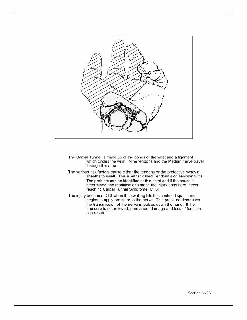
Section 6 - 23
The Carpal Tunnel is made up of the bones of the wrist and a ligamentwhich circles the wrist. Nine tendons and the Median nerve travelthrough this area.
The various risk factors cause either the tendons or the protective synovialsheaths to swell. This is either called Tendonitis or Tenosynovitis.The problem can be identified at this point and if the cause isdetermined and modifications made the injury ends here, neverreaching Carpal Tunnel Syndrome (CTS).
The injury becomes CTS when the swelling fills this confined space andbegins to apply pressure to the nerve. This pressure decreasesthe transmission of the nerve impulses down the hand. If thepressure is not relieved, permanent damage and loss of functioncan result.

Section 6 - 24
Work related back injuries fall into two primary categories:1 Muscular injuries2 Spinal Column injuries
Of the two we can recover best from muscle injuries. Muscle tissue heals veryfast, with the worst normal muscle pull healing within 10 days.We must understand that a pulled muscle, if the individual is injured whiledoing the normal duties of his or her job, it is a warning that their back is notstrong enough to do the work. This should be taken as a clue by the worker toget some exercise and strengthen the back back up. Proper exercises should beobtained from a doctor, physical therapist, or occupational therapist thatknows the individuals back history.
TWO KINDS OF BACK INJURIES
MUSCULAR SPINAL

Section 6 - 25
Resting Dynamic Static
bloodflow
needed
bloodflow
supplied
bloodflow
needed
bloodflow
needed
bloodflow
supplied
bloodflow
supplied
Other than being in good physical shape, the best precaution that an employeecan take to reduce the chance of pulling a muscle is to warm-up beforeperforming lifts. When the individual is sitting, driving, on break, or any otheractivity not demanding a lot of back effort, the muscles are in a resting state ofminimal blood flow. The muscles have only enough blood flow to maintainhealth, not enough to perform heavy lifting.If the person jumps right into lifting from this state then there is a delay beforethe blood flow catch up to the demand of dynamic work ( work where themuscle is flexing and relaxing repeatedly). During this time the muscle mustuse reserve energy in the cells to perform the lifting.The problem with this is that the cells only have a minor amount of reservepower (only enough for 2 or 3 good exertions). The problem develops laterwhen the individual is required to do some period of static work (where theperson is made to hold a weight for an extended period of time). With staticwork the muscle remains flexed, cutting off all blood flow. This is what themuscle was saving that reserve for and if it is not there the muscle quits. It iswhen the first muscle quits ( there are over 200 muscles in the back and torso)that a muscle is pulled.Therefore, stretching of even the most minor kinds, before the individual goesfrom a resting condition to lifting, will go a long way in preventing the earlydepletion of the energy. This will mean the energy is there for the unexpectedstatic lifts.

Section 6 - 26
• The three main components of the spine are the vertebrae, spinal cord, andthe discs. The weak links in this system are the discs.
• There are two important factors which must be considered when dealingwith the spine. The discs have no direct blood supply which means that allnutrients must be transmitted from the surface of the vertebra. Therefore, thediscs actually take longer to heal than bones.
• The second factor is that there are no nerve connections to the discs.This means that when the disc is injured you don’t know it. Because you don’tknow of the injury, you do not make any changes and keep doing what younormally do, making the healing process even slower.
Vertebrae
Top View
Side View

Section 6 - 27
• Because the discs and surrounding bone heal slowly, and are aggravated bysustained activity, scar tissue is formed. This scar tissue impedes the flow ofnutrients to the disc. This process causes increasing effects as time progresses.
Micro-fractures in Vertebral Endplate
Scar tissue from healing fractureshinders passage of nutrients to disc resulting in gradual weakeningand de-generation.
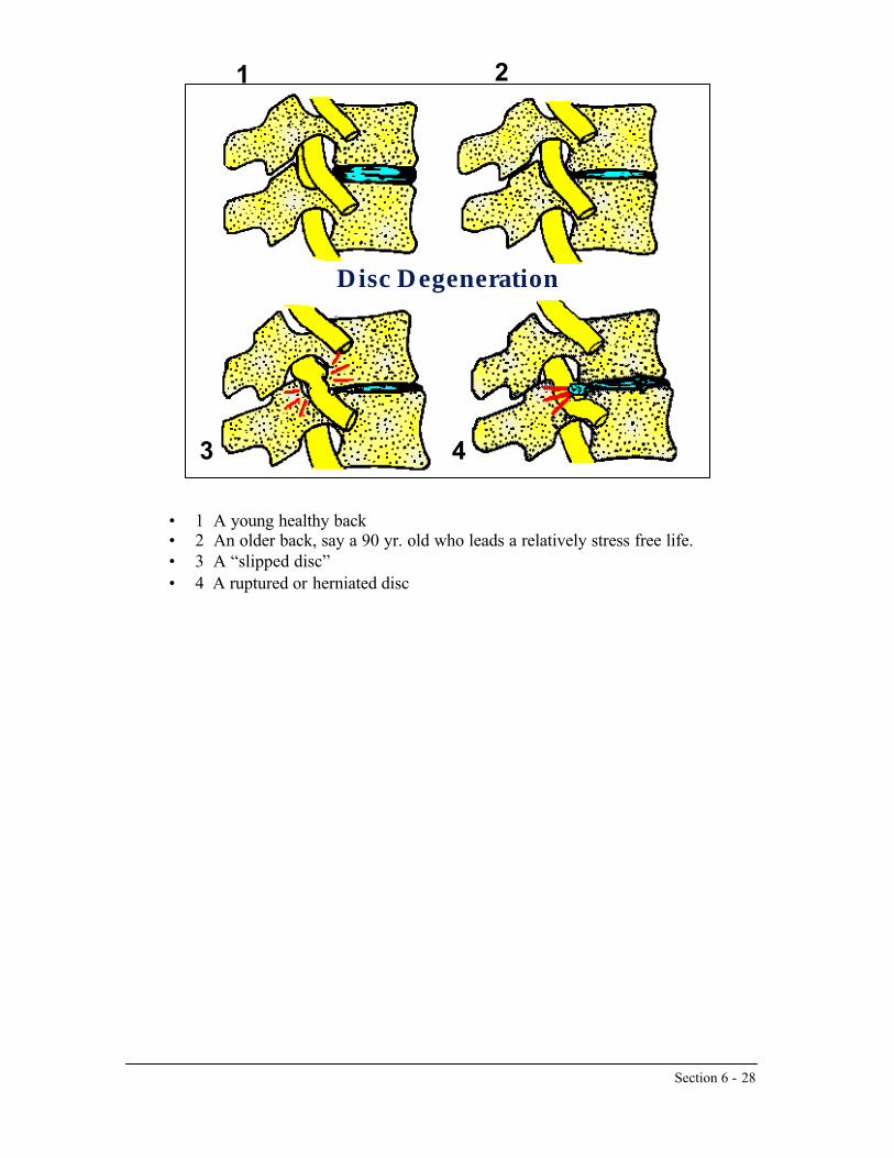
Section 6 - 28
• 1 A young healthy back• 2 An older back, say a 90 yr. old who leads a relatively stress free life.• 3 A “slipped disc”• 4 A ruptured or herniated disc
Disc Degeneration
1 2
3 4

Section 6 - 29
Hierarchy of Controls
Ergonomics
Engineering ControlsWorkstation DesignTool DesignProcess ModificationMechanical Assist Administrative Controls
TrainingJob RotationPacingPolicyJob Enlargement
Personal Protective EquipmentGlovesWrapsShields
FIRST CHOICE
SecondChoice
Last & Least

Section 6 - 30
BACK INJURIES

Section 6 - 31
WHAT YOU CAN DONow, what can you do to protect yourself. Everyone has heard of the “ProperWay To Lift” right?
!! Bend the knees, Keep your back straight, and Lift with the legs !!The problem is that it is very difficult to find a situation or job where theworker can consistently do that. That is why we are not going to talk aboutthat. What I am going to do is to give you four elements of lifting or types ofactions to avoid. If you cannot do the Proper Lift (which incorporates all fourelements) than you can avoid some of the actions that will do the most damageto your back.

Section 6 - 32
WHAT YOU CAN DONow, what can you do to protect yourself. Everyone has heard of the “ProperWay To Lift” right?
!! Bend the knees, Keep your back straight, and Lift with the legs !!The problem is that it is very difficult to find a situation or job where theworker can consistently do that. That is why we are not going to talk aboutthat. What I am going to do is to give you four elements of lifting or types ofactions to avoid. If you cannot do the Proper Lift (which incorporates all fourelements) than you can avoid some of the actions that will do the most damageto your back.
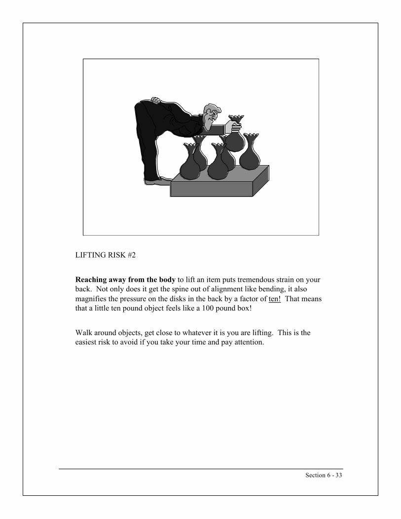
Section 6 - 33
LIFTING RISK #2
Reaching away from the body to lift an item puts tremendous strain on yourback. Not only does it get the spine out of alignment like bending, it alsomagnifies the pressure on the disks in the back by a factor of ten! That meansthat a little ten pound object feels like a 100 pound box!
Walk around objects, get close to whatever it is you are lifting. This is theeasiest risk to avoid if you take your time and pay attention.

Section 6 - 34
LIFTING RISK #3
Twisting the back puts torque on the spine doing localized damage to thedisks. It also makes your back use the small muscles on the side of your backto do the lifting. These muscles are very weak and are the most commonlypulled muscles.You want to use the muscles in the center of the back. To do this you onlyneed to remember to point you toes at whatever it is you are lifting. This willmake it so that you will use the best muscles for the job.

Section 6 - 35
LIFTING RISK #4
High speed or acceleration will also do a lot of damage. The faster you loadthe weight on the the body the less time the tissue has to react properly. In thiscase the body reacts like any material.If you have nylon cord and you are measuring how much force it will take tobreak it you can load weight on in two ways. You can attach the weight anddrop it or you can gently apply the weight so that the cord does not snap tauntquickly. What you will find is that it takes a lot less weight to break the cordwhen you drop the weight on quickly. Your body is going to react the sameway.If you lift items very quickly ( either by catching something or grabbing it andtossing it quickly) you greatly increase your chances of causing an injury.
So, slow down and make sure you are in complete control of the move. If it issomething that is so heavy you need to get it moving fast to sling it onto a pileor some high point that is a good clue that two people should be performingthe lift.

Section 6 - 36
REMEMBER
You don’t have to avoid all of these risk factors all of the time to reduce yourchances of getting hurt. If you can avoid just 3 or 2 or even only 1 of thesefactors you will greatly extent the life of your back and reduce the chances ofhurting yourself.
It only takes a few seconds before starting a lifting job to look and see if youare going to need to do any of these elements and find a way to avoid them.

Section 6 - 37
These are two twin brothers.
The on e on the left is absolutely not athletic, in fact he has never doneanything physical in his life. He’s the guy who always gets sand kicked in hisface at the beach and can’t do anything about it.
His brother on the right is the complete opposite. He is very athletic, liftsweights, lifts small cars to impress the girls, and is the one usually kicking thesand on the beach.
Of these two, which do you think is more likely to suffer from a serious,debilitating spinal injury in his lifetime?
My money is on the brother on the right. Remember they are twins. If youlook at an x-ray of their backs they are identical. Therefore, he is going towear it down much much faster, not feeling any of the damage until it is twolate.
It is important to be strong and fit and be capable of lifting what you need.But, you have to play it smart. Just because you can lift something in a certainway and not feel any pain does not mean you are not hurting your back. Thatis why it will pay in the long run to lift smart and avoid those risk factors.

Section 6 - 38
MAN VS. MACHINE
•DECISION MAKING•LOW REPETITION ACTIVITIES•LOW FORCE APPLICATION•DELICATE FORCE APPLICATION
•TAKING INSTRUCTION•HIGH REPETITION ACTIVITIES•HIGH FORCE APPLICATION•HAZARDOUS ENVIRONMENTS

Section 6 - 39
STATURE
EYE
SHOULDER
ELBOW
HIP
KNEE
21.67”21.5”19.3”20.0”
N.A.E.A.
L.A.
36.0”36.4”32.7”34.0”
N.A.E.A.
L.A.
43.5”43.3”40.8”40.9”
N.A.E.A.
L.A.
N.A.E.A.
L.A.
69.1”68.6”65.2”65.1”
N.A.E.A.
L.A.
64.6”64.4”60.7”60.9”
N.A.E.A.
L.A.
56.7”56.5”52.8”53.2”
N.A.= NORTH AMERICA E.= EUROPE A.= ASIA L.A.= LATIN AMERICA
50thPERCENTILE
MALE

Section 6 - 40
D
E
C
B
A
Horizontal Work Envelope
A-Normal reach radiusB-Sitting/Standing distanceC-Extended reach radiusD-Beginning work distanceE-Optimum work area
Max = 15”Max = 9”Max = 22”Ideal = 4”10” x 10”

Section 6 - 41
SIT OR STAND?Type of TaskLifting more than 11lbs
Work below elbow height
(e.g. packaging or assembly)
Extended horizontal reaching
Light assembly with repetitive movements
Fine manipulation and precision tasks
visual inspection and monitoring
Frequent moving around
First ChoiceStanding
Standing
Standing
Sitting
Sitting
Sitting
Sit-Standing
Second ChoiceSit-Standing
Sit-Standing
Sit-Standing
Sit-Standing
Sit-Standing
Sit-Standing
Standing

Section 6 - 42
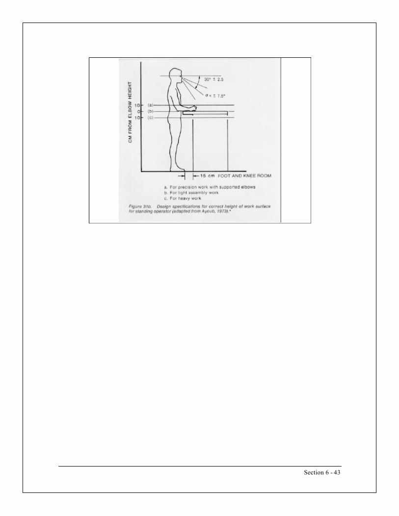
Section 6 - 43

Section 6 - 44

Section 6 - 45
A > 4” B = (for power grips) 1.5” C = 3” to 3.5” (for precision operations) .45”
Manual Tool Dimensions


Industrial H
ygiene for Pow
er Presses


Section 7 - 1
HAZARD COMMUNICATION (HAZCOM)
• Purpose: To insure all employees are aware of the hazards from the chemicals they are incontact with. Examples of jobs requiring a HAZCOM program include manufacturing,warehouse operations, janitorial, laboratory, etc.
• OSHA Standard:• 29 CFR 1910.1200 (Industrial)• 29 CFR 1926.59 (Construction)
• Written Program
• Identify responsibilities
• Who is responsible for training• Who is responsible for ordering/maintaining MSDSs
• Container labeling
• Legible• Chemical name• Target organs• Manufacturer’s name and address
• Material Safety Data Sheets (MSDSs)
• Where located• How to obtain
• Employee training
• Frequency• Who conducts training• Who needs to be trained
• Non-routine tasks
• Unusual operations• Once-a-year operations
• Piping systems
• Diagrams• Contents• Shut-off valves

Section 7 - 2
HAZARD COMMUNICATION (HAZCOM) (continued)
• Contractors
• Notification procedures• Training contractors of company hazards• Training company employees of contractor hazards
• Chemical inventory
• What company has on hand/quantity• Where located
• Training
• Who needs to be trained
• New hire orientation• Transfers• Temporary hires• New operations• New products• After accidents/incidents
• Overview of HAZCOM requirements • Chemicals present in workplace • Location/availability of written program • Health effects of chemicals • Identification of chemicals in workplace • How to lessen or prevent exposures
(PPE, work practices) • Engineering controls the company is using • Emergency procedures if exposed to chemicals • MSDSs
• Location• How to read• Labeling requirements

Section 7 - 3
HAZARD COMMUNICATION (HAZCOM) (continued)
Related OCOSH Courses• IHY 212: “Hazard Communication”• IHY 317: “Hazardous Waste Operations and Emergency Response - Awareness”• IHY 335: “Hazardous Waste Operations and Emergency Response- Operations”• IHY 318: “Hazardous Waste Operations and Emergency Response - Technician”• IHY 319: “Hazardous Waste Operations and Emergency Response - Refresher”

Section 7 - 4
CONFINED SPACES
• Purpose: To identify locations within a facility that may pose a hazard to any employeeentering them and to develop a formalized plan to address how employees will enter theseareas
• OSHA Standard: 29 CFR 1910.146 • Difference between confined space and permit-required confined space
• Confined Space
• Is large enough so an employee can bodily enter and perform work• Has limited or restricted means of entry or exit• Is not designed for continuous human occupancy
• Permit-Required Confined Space
• Contains, or has the potential to contain, hazardous atmosphere• Contains material that has the potential to engulf entrant (i.e., grain silo)• Has internal configuration such that an entrant could become trapped or
asphyxiated• Contains any other recognized serious health or safety hazard (noise,
moving parts, electrical, poor visibility) • Workplace Evaluation: Employer shall evaluate facility to determine if any spaces are
permit-required. If so, employer shall:• Inform employees by posting signs, or other methods, of the existence, location and
danger• If employees ARE NOT to enter permit-confined spaces, then employer shall take
effective measures to prevent entry• If employees are to enter, then employer shall develop a written confined space
entry program
• Written Program• Permit• Measures to prevent unauthorized entry• Means to identify and evaluate hazards before entry• Procedures for safe operations• Provision of equipment (testing and monitoring, communication, PPE, rescue)• Designate employees by role (i.e., entrants, attendants, entry supervisors,
atmosphere monitoring) and describe training for each• Procedures for summoning rescue personnel

Section 7 - 5
CONFINED SPACES (continued)
• Contractor requirements: Employer must:
• Inform contractor that space is a permit-required confined space and contractormust comply with the permit-required entry program
• Tell the contractor why the space is permit-required• Apprise the contractor of procedures that the employer has implemented• Contractor must inform employer of procedures contractor will use
• Training
• Training shall establish employee efficiency• Certification must be available for inspection
• Authorized entrants
• Know hazards• Use equipment• Communication with attendant• Entry/exit procedures
• Attendants
• Know hazards• Know effects of exposures• Know who is authorized to enter• Communication procedures• Emergency rescue procedures
• Entry Supervisor
• Know hazards• Use of the permit system• Know when to terminate entry• Verify rescue procedures
• Rescue and Emergency Services (if on-site)
• Rescue procedures/equipment• One member must be certified in CPR/First Aid• Practice once every 12 months
Related OCOSH Courses IHY 214: “Confined Space Assessment and Work”

Section 7 - 6
HEARING CONSERVATION
• Purpose: To protect employees from effects of hazardous noise. • OSHA Standard: 29 CFR 1910.95 • Program Elements
• Employee monitoring (Need to know what the sound levels are) • Audiometric monitoring
• Baseline• Annual• Threshold shifts
• Hearing protectors
• Identify where/when to wear• Should be used as last resort
• Recordkeeping
• Noise measurements: 2 years• Audiometric records: duration of employment (note: OSHA requires
employer to keep medical records for duration of employment plus 30years)
• Training
• Conducted annually• Effects of hazardous noise• Purpose of hearing protectors, advantages and disadvantages of various types• Instructions of selection, fitting, use, and care Purpose of audiometric testing and explanation of results
Related OCOSH Courses• IHY 204: “Basic Industrial Noise and Hearing Conservation”

| PRIORITIES PAGE |
Metalworking/Machining Fluids
Millions of workers engaged in the manufacture of automobiles, farm equipment, aircraft, heavy machinery, and other hardware are exposed to machining fluids. Occupational exposure to these fluids has resulted in various cancers, respiratory diseases, and skin problems. There is evidence of impaired health at levels well below the Permissible Exposure Limit (PEL) for oil mists (5 mg/m3 time weighted average (TWA)) and the "nuisance dust" exposure limits applicable to all other machining fluids (15 mg/m3 TWA for total particulate). In order to improve worker protection, OSHA is designating metalworking/machining fluid exposure as a priority for comprehensive rulemaking. OSHA intends to work together with business, labor and the professional community to develop this rule in a consensual manner.
Hazard Description
Machining or metalworking fluids are in widespread, high volume use throughout the manufacturing industries for their coolant, lubricant, and corrosion resistant properties during operations such as metal grinding, boring, drilling, and turning. These fluids are complex mixtures of oils, detergents, surfactants, biocides, lubricants, anti-corrosive agents, and other potentially toxic ingredients.
There is an extensive body of scientific literature which demonstrates that worker exposure to machining fluids of all types is strongly associated with cancer (several respiratory and digestive sites) and non-malignant respiratory effects (occupational asthma). Because the usage patterns, chemistry and toxicology of these materials is very complicated, it has been difficult to determine precise links between specific fluid formulations or specific ingredients with specific health effects in exposed workers. The risks for various cancers are dose-related to all major types of machining fluids, but the evidence about cancer excesses is based on information about past exposures which may differ qualitatively and quantitatively from current exposures. It is clear, however, that the risk of occupational asthma and related respiratory conditions is related to current exposure levels and current materials.
Cancer
More than a dozen recent epidemiological studies have reported statistically significant increases in one or more cancer sites, such as esophagus (1), stomach (2-4), pancreas (4-8), larynx (9, 10), colon (1), rectum (8, 9) and other cancers (1-13). In these studies, for many groups of workers, the risk has been two to ten times the expected rate.
There is strong epidemiologic evidence that exposures to all types of machining fluids cause substantially elevated risk of cancer. The most comprehensive cohort mortality study published provides strong evidence that exposure to soluble or synthetic fluids in grinding operations is associated with esophageal and pancreatic cancer; that straight fluids are associated with rectal cancer; and that synthetic fluids are associated with pancreatic and possibly colon cancer. (5, 8) For each cancer site the risk increases as the duration of exposure increases. For example, the risk of esophageal cancer reaches 12-fold with more than one year exposure to grinding. The risk for colon and pancreatic cancer reach 2- to 3-fold after three years of exposure to synthetic machining fluids. The risk for rectal cancer is 3-fold after one year of exposure to straight machining fluids.
Respiratory Effects
Page 1 of 4OSHA Priorities - Metalworking / Machining Fluids
07/23/2001http://www.osha.gov/oshinfo/priorities/metal.html

Occupational respiratory illnesses due to exposure to machining fluids include respiratory irritation, bronchitis, lipoid pneumonia, hypersensitivity pneumonitis, and extrinsic asthma. (12, 13, 15, 16) In particular, evidence from clinical studies and medical surveillance in both the U.S. and U.K. document that occupational asthma is caused by exposure to several different types of machining fluids (17-20). Epidemiologic evidence also suggests that exposure to machining fluids is related to both asthma incidence (21, 22) and asthma mortality (6). Overall the evidence indicates that risk of asthma exists in several different settings with different types of fluids.
Acute loss of forced expiratory lung volume (FEV1) of greater than 5% across the workshift has been associated with exposure to each of the major types of machining fluids in three independent cross-sectional studies (15, 23, 24). These lung function changes are correlated with occupational asthma. Loss of lung function became worse as exposures increased, supporting the conclusion that exposures below 1.0 mg/m3 total particulate (and possibly below 0.5 mg/m3) cause increased risk.
Workers experience skin contact with machining fluids as a result of splashing, dripping or leaking. Skin problems include irritation and allergic contact dermatitis (16). They also inhale mists and aerosols of these fluids generated during high speed, high friction, metalworking operations. There are many well known effective techniques available to reduce worker exposure, including protective clothing, mechanical splash guards and enclosures, local exhaust ventilation, preventive maintenance programs, and others.
Current Status
OSHA has permissible exposure limits (PEL) of 5 mg/m3 as an 8-hour TWA for mineral oil mists, and 15 mg/m3 TWA (total particulate) and 5 mg/m3 TWA (respirable fraction) for "nuisance dusts" (also called "particulates not otherwise regulated"), but there are no specific standards for machining fluids and most of their ingredients. Toxic effects have been reported among workers exposed to mineral oil mists below the current PELs, as noted above. The OSHA inspection data system (IMIS) contains more than 1,400 samples for airborne oil mist collected over the past two decades. In over 500 samples collected from 1990-1994 approximately 60% were below or equal to 0.5 mg/m3 and approximately 25% were greater than 1.0 mg/m3. The trend has been downward. For example, from 1980-1984 more than 50% of the samples were greater than 1.0 mg/m3.
The International Union, United Automobile, Aerospace and Agricultural Implement Workers of America (UAW) petitioned OSHA in December 1993 for an Emergency Temporary Standard (ETS) to lower the PEL for oil mists to 0.5 mg/m3 of total particulate. The UAW also petitioned the Environmental Protection Agency (EPA) for a S4 Test Rule under the Toxic Substances Control Act (TSCA). OSHA denied the UAW's request for an emergency standard but indicated that it would continue to consider a permanent standard.
There have been private sector recommendations, as well, to lower the permissible exposure limits. For example, the authors of the largest ongoing epidemiologic study of workers exposed to machining fluids, recommended to the UAW/General Motors Occupational Health Advisory Board that machining fluid exposures be kept below 0.5 mg/m3 total particulate: "Results from both the respiratory morbidity study and the mortality study suggest associations between machining fluid exposure and respiratory disease or cancer that are consistent with an interpretation of causality. Our initial dose-response analyses suggest that an exposure level of 0.5 mg/m3 would minimize any adverse health effect of worker exposure to machining fluids." (1)
The National Institute for Occupational Safety and Health (NIOSH) issued a draft NIOSH Special Hazard Review of the Metalworking Industry in May 1994; work is currently underway to complete the document. OSHA, NIOSH, and EPA are working on a joint Hazard Alert on machining fluids, planned for completion after the NIOSH Special Hazard Review.
In November 1994, NIOSH sponsored a 2-day information gathering meeting with representatives of government, labor, fluid manufacturers, and fluid users. In November 1995 over 700 representatives of business, labor and academia participated in a four day symposium on The Industrial Metalworking Environment: Assessment and Control, sponsored by the American Automobile Manufacturers
Page 2 of 4OSHA Priorities - Metalworking / Machining Fluids
07/23/2001http://www.osha.gov/oshinfo/priorities/metal.html

Association (AAMA) in cooperation with the Independent Lubricant Manufacturers Association, the United Automobile Workers, OSHA, NIOSH and EPA. There was substantial evidence and viewpoints presented which supported the conclusion that existing standards are inadequate to protect worker health, that substantially lower exposures are feasible, and that the private sector is interested in working cooperatively with government on strategies to achieve lower exposures.
EPA is screening 95 metalworking fluid chemicals referred to EPA by NIOSH for the selection of possible testing candidates under Section 4 of TSCA.
Rationale
Machining fluids meet the criteria for designation as an OSHA priority. There is a very large number of workers exposed to machining fluids; the health effects are serious; there is extensive scientific evidence of risk; and there are available control methods for reducing exposure. There is substantial evidence of serious health effects at exposure levels below existing relevant standards. There is also considerable interest within both business and labor in working with government agencies to find ways to reduce worker exposure. OSHA is designating metalworking/machining fluid exposure as a priority for comprehensive rulemaking. OSHA intends to work together with business, labor and the professional community to develop this rule in a consensual manner.
References
1. Monson R, et al. (1992). Final Report to GM-UAW Occupational Health Advisory Board on Health Effects of Exposure to Machining Fluids. Harvard School of Public Health, unpublished report. October 30, 1992 (OSHA Docket No. 372, Ex. No. 2-7A).
2. Park R, et al. (1994). Mortality at an Automobile Stamping and Assembly Complex. Am J Ind Med. 26:449-463.
3. Park RM et al. (1988). Causes of Death Among Workers in a Bearing Manufacturing Plant. Am J Ind Med. 13:569-580.
4. Silverstein M et al. (1988). Mortality Among Bearing Plant Workers Exposed to Metalworking Fluids and Abrasives. J. Occup Med. 30(9):706-714.
5. Rotimi C, et al. (1993). Retrospective Follow-up Study of Foundry and Engine Plant Workers. Am J Ind Med. 24:485-498.
6. Eisen EA, et al. (1992). Mortality Studies of Machining Fluid Exposure in the Automobile Industry I: A Standardized Mortality Ratio Analysis. Am J Ind Med. 22:809-824.
7. Mallin K, et al. (1986). A Proportional Mortality Ratio Study of Workers in a Construction Equipment and Diesel Engine Manufacturing Plant. Am J Ind Med. 10:127-141.
8. Vena JE, et al. (1985). Mortality of Workers in an Automobile Engine and Parts Manufacturing Complex. Br J Ind Med. 42:85-93.
9. Tolbert PE, et al. (1992). Mortality Studies of Machining-Fluid Exposure in the Automobile Industry II: Risks Associated With Specific Fluid Types. Scand J Work Environ Health 18:351-360.
10. Eisen EA, et al. (1994). Mortality Studies of Machining Fluid Exposure in the Automobile Industry III: A Case-control Study of Larynx Cancer. Am J Ind Med. 26:185-202.
11. Acquavella JF, Leet TL. (1991). A Cohort Study Among Workers at a Metal Components Manufacturing Facility. J Occup Med. 33(8):896- 900.
12. Ameille J, et al. (1995). Respiratory Symptoms, Ventilatory Impairment, and Bronchial Reactivity in Oil Mist-Exposed Automobile Workers. Am J Ind Med 27:247-256.
13. International Agency for Research on Cancer (1984). IARC Monographs on the Evaluation of the Carcinogenic Risks of Chemicals to Humans: Mineral Oils (Lubricant Based oils and Derived Products), Vol. 33, Lyon, France: IARC, pp. 87-168.
14. Eisen EA, et. al. (1992). Mortality Studies of Machining Fluids; An Exposure-Response Analysis of Respiratory and Digestive Cancers. Proceedings of the Ninth International Symposium on Epidemiology in Occupational Health, Cincinnati, OH. NIOSH Publication No. 94-112 (pp. 113-116).
15. Kennedy SM et al. (1989). Acute pulmonary responses among automobile workers exposed to aerosols of machining fluids. Am J Ind Med 15:627-641.
16. Sprince N, et al. (1994) Chapter 34, Oils and Related Petroleum Derivatives, in Textbook of Clinical Occupational and Environmental Medicine, Rosenstock L and Cullen MR, eds.,
Page 3 of 4OSHA Priorities - Metalworking / Machining Fluids
07/23/2001http://www.osha.gov/oshinfo/priorities/metal.html

Saunders, 1994. 17. Hendy MS, Beattie BE, Burge PS (1985). Occupational Asthma Due to an Emulsified oil mist.
Br J Ind Med 42: 51-54. 18. Robertson AS, Weir DC, Burge PS (1988). Occupational Asthma Due to Oil Mists. Thorax 43:
200-205. 19. Gannon PFG, Burge PS (1991). A Preliminary Report of a Surveillance Scheme of
Occupational Asthma in the West Midlands. Br J Ind Med 48(9): 579-582. 20. Rosenman KD, Reilly MJ (1993) Annual Report on Occupational Asthma in Michigan.
Michigan Department of Public Health, Bureau of Occupational Health, Lansing, Michigan. 21. Eisen EA (1995). Healthy Worker Effect in Morbidity Studies. Medicina del Lavoro, in press. 22. Greaves IA, Eisen EA, Smith TJ, et. al. (1995). Respiratory Health of Automobile Workers
Exposed to Metal Working Fluid Aerosols. II: Respiratory Symptoms. Amer J Indust Med (submitted).
23. Kreibel D et. al. (June 1, 1994). Field Investigations of Acute Respiratory Effects of Machining Fluids. Final Report submitted to UAW/GM National Joint Committee on Occupational Health and Safety.
24. Robins T et. al. (December 9, 1994). Respiratory Effects of Machining Fluid Aerosols. Final Report to the UAW/GM Occupational Health Advisory Board.
| USDOL | CONTACT INFORMATION | DISCLAIMER |
Page 4 of 4OSHA Priorities - Metalworking / Machining Fluids
07/23/2001http://www.osha.gov/oshinfo/priorities/metal.html


Lockout/T
agout Standard

Section 8 - 1
Sample Program
Hazardous Energy Control Procedures Lockout
I. Purpose and Scope
Effective hazardous energy control procedures will protect employees during machine and equipment servicing and maintenance where the unexpected energization, start up or release of stored energy could occur and cause injury, as well as while working on or near exposed deenergized electrical conductors and parts of electrical equipment. Hazards being guard against include being caught in, being crushed by, being struck by, being thrown from, or contacting live electrical circuits/parts.
The procedure herein established (III - VIII) will insure that machines and equipment are properly isolated from hazardous or potentially hazardous energy sources during servicing and maintenance and properly protect against reenergization as required by 29 CFR 1910.147.
While any employee is exposed to contact with parts of fixed electrical equipment or circuits which have been deenergized, the circuits energizing the parts shall be locked out and tagged in accordance with the requirements of 29 CFR 1910.333 (b) (2). SEE THIS OSHA STANDARD.
Only when disconnecting means or other devices are incapable of being locked out, and until lockout capability is provided, will a tagout procedure (without lockout), be utilized. SEE APPENDIX A.
II. Enforcement
Any employee who fails to follow these procedures will face disciplinary action in accordance with those listed in the company handbook.

Section 8 - 2
III. Definitions
Authorized employee - a person who locks out machines or equipment in order to perform servicing or maintenance on that machine or equipment. An affected employee becomes an authorized employee when that employee’s duties include performing servicing or maintenance which exposes him/her to potentially hazardous energy.
Affected employee - an employee whose job requires him/her to operate /use a machine or equipment or work in an area in which servicing or maintenance is being performed under lockout.
Energy isolating device - a mechanical device that physically prevents the transmission or release of energy, including but not limited to the following: A manually operated electrical circuit breaker; a disconnect switch; a manually operated switch by which the conductors of a circuit can be disconnected from all ungrounded supply conductors, and in addition, no pole can be operated independently; a line valve; a block; and any similar device used to block or isolate energy. Push buttons, selectors switches, and other control circuit type devices are not energy isolating devices.
Other employee - an employee whose work operations are or may be in an area where energy control procedures may be utilized.
For additional definitions see 29 CFR 1910.147 (b).
IV. Authorization / Responsibility
Appropriate employees will be instructed in the safety significance of the lockout procedures. Appendix B isa list of employees authorized to lockout. Appendices C and D are a list of job titles for affected and other employees.
V. Rules
A. Locks, chains, wedges, or other hardware which meet the requirements defined in 1910.147 (c) (5) (ii)shall be provided by the company.
B. Lockout devices shall be singularly identified. They shall be the only devices used for controlling energy and shall not be used for other purposes.
C. The lockout devices shall indicate the identity of the employee applying the devices.
D. All machines/equipment shall be locked out to protect against accidental or inadvertent operation when such operation could cause injury to personnel. Lockout will also apply when working on or near exposed deenergized electrical circuits / parts.
E. No employee shall attempt to operate any switch, valve, or other energy isolating device which is locked out.
F. Each lockout device shall only be removed by the employee who applied the device. (Exception: seeVII. B. 2.)

VI. Lockout Procedures and Techniques
A. Preparation for Shutdown.
1. In preparation for lockout, an initial survey must be made to locate and identify all energy isolating devices to be certain which switch, valve, or other energy isolating devices apply to the machine / equipment to be locked out. (See Appendix E for Energy Source Evaluation) More than one energy source (electrical, hydraulic, pneumatic, chemical, thermal, or
others) may be involved.
2. Before an authorized or affected employee turns off a machine or piece of equipment, the authorized employee must have knowledge of the type and magnitude of the energy to be controlled, and the methods or means to control the energy (see Appendix F for Specific Energy Control Procedures).
Note: If work to be performed involves employees working on or near exposed deenergized electrical parts. (See 29 CFR 1910.333).
B. Machine or Equipment Shutdown.
1. All affected employees shall be notified that a lockout system is going to be utilized and the reason for it, before the controls are applied.
2. If the machine or equipment is operating, shut it down by normal stopping procedure. (Depress stop button, open toggle switch, etc.)
C. Machine or Equipment Isolation.
Physically locate and operate the switch, valve, or other energy isolating devices so that the equipment is isolated from its energy sources and apply adequate hardware.
D. Lockout Device Application.
1. Authorized employees shall lockout the energy isolating devices with assigned individual locks.
2. Lockout devices shall be applied so that they will hold the energy isolating devices in a “Neutral” or “Off” position.
E. Stored Energy.
All stored or residual energy in rams, flywheels, springs, pneumatic, or hydraulic systems, etc. shall be blocked or dissipated. If there is a possibility of reaccumulation of stored energy, verification of isolation must be continued until servicing or maintenance is completed.
F. Verification Of Isolation.
Prior to starting work on machines or equipment that have been locked and after ensuring that no personnel are exposed, the authorized employee shall operate the push button or normal operating controls to verify that the appropriate equipment or machine has been deenergized and make certain itl will not operate.
Section 8 - 3

CAUTION: Return Operating Controls to the “Neutral” or “Off” Position After the Test.
The machine / equipment is now locked out. Servicing or maintenance may now occur.
VII. Removal Of Lockout Devices
A. After the servicing and / or maintenance is completed and before the lockout devices are removed andenergy is restored, the sequence of activities in Appendix F shall be completed by the authorizedemployee(s).
B. If the authorized employee who applied the lock is not available, the supervisor shall take the followingsteps:
* Clear the machine or equipment of tools and materials.* Remove employees from the machine or equipment.* Remove the lockout device.* Energize and proceed with testing or positioning.* Deenergize all systems and reapply energy control measures in
accordance with procedures set forth under SECTION VI.
VIII. Additional Requirements
A. In the preceding steps, if more than one individual is required to lockout machines / equipment (grouplockout), the following procedures shall be implemented to provide protection to all employees.
1. A primary authorized employee will be designated and responsible for the number of people working under the protection of the group lockout device. The primary authorized employee will ascertain the exposure status of the individual member participating in the group lockout to ensure continuity of protection for each individual. In addition, this primary authorized employee will be responsible for notifying affected employees before and after lockout procedures are performed.
2. Each authorized employee will place his/her own personal lockout device on the energy isolating device(s).
3. When an energy isolating device cannot accept multiple locks, a multiple lockout system must be used. Specific group lockout procedures are outline in Appendix F.
B. Shift or Personnel Changes - If a lockout procedure will extend into the following shift, the authorizedemployee who originally placed the lock will remove it and it will immediately be replaced with the lock of theauthorized employee who is to continue the repair or maintenance on that equipment or machine for thefollowing shift.
C. Cord and Plug Connected Equipment - If servicing or maintenance is performed on cord and plugconnected equipment the following procedure shall be performed to protect employees.
1. Unplug equipment from its electrical socket.
Section 8 - 4

Section 8 - 5
2. Place a lockable cover over the plug and a lock on the plug cover during machine / equipment servicing or maintenance.
D. Outside Contractors - If outside contractors perform servicing or maintenance that requires lockout, theSafety Director shall take the following steps.
1. Inform the outside contractor of out company’s lockout procedures and supply them with a copy.
2. Obtain and review a copy of the outside contractor’s lockout procedures.
3. Ensure that our employees understand and comply with the responsibilities and prohibitions of the outside contractor’s lockout procedure.
E. Training
1. Authorized employees shall receive training covering:
* Recognition of hazardous energy sources.* Types and magnitude of hazardous energy in the workplace.* Methods, devices, and procedures used to lockout, verify lockout, and otherwise control hazardous energy on all pieces or types of equipment (including cord and plug connected equipment).* Procedures for removing locks and returning a machine or piece of
equipment to operation.* Transfer of lockout responsibilities.* Group lockout procedures.
2. Affected and all “other” employees shall receive training so that they are able to:
* Recognize when energy control procedures are being implemented, and
* Understanding the purpose of the procedures and the importance of not attempting to start up or use the machine / equipment that has been locked out.
Note: All training will be certified (See Appendix G).
F. Retraining - Authorized and affected employees shall receive retraining in proper application of lockoutprocedures when there is a change in:
* Job assignment(s) that expose an authorized employee to new hazards or lockout procedures.
* Machines, equipment, or processes that present a new hazard or require modified lockout procedures.* Energy control procedures for a piece or type of equipment.* Or when it becomes known that an employee incorrectly performs
lockout procedures.
Retraining will re-establish employee proficiency in lockout, and ensure that employees are knowledgeableof new or revised procedures. All retraining will be certified (see Appendix G).

Section 8 - 6
G. Periodic Inspections
1. An inspection of the energy control procedures will be conducted annually and will be certified (see Appendix H).
2. Energy control procedures for each machine or type of machine must be inspected.
3. The inspection shall include a review of lockout responsibilities with each individual authorized to lockout the machine / equipment.
4. The person who performs the inspection must be authorized to perform the lockout procedures being inspected. The inspector cannot, however, review his/her own use of lockout procedures.
5. Any deviations or inadequacies identified shall be immediately addressed.

Section 8 - 7
APPENDIX A
TAGOUT PROCEDURES
A. When a disconnecting means or other energy isolating device is incapable of being locked out, atagout system shall be utilized. A tag used without a lock, shall be supplemented by at least onadditional safety measure that provides a level of safety equivalent to that obtained by use of a lock such asopening an additional disconnecting device, removal of an isolating circuit element, blocking of acontrolling switch or the removal of a valve handle to reduce the likelihood of inadvertent energization.
B. Only tags furnished by the company which meet the requirements of 1910.147 (c) (5) (ii) and (iii) shall be used.
C. All employees shall be trained in the use and limitations of tags as described in 1910.147 (c) (7) (ii) and (d) (4) (iii).
D. All employees must be able to understand the hazard warning written on the tags such as: DO NOT START, DO NOT OPEN, DO NOT CLOSE, DO NOT ENERGIZE, DO NOT OPERATE.
E. On machines and equipment where tagout is used in lieu of lockout, the Periodic Inspection required by 1910.147 (c) (6) shall include the affected as well as the authorized employee(s). The periodic inspection shall be certified onappendix H.
F. If tagout is used all other lockout rules and procedures apply.
NOTE: Should the machine / equipment required upgrade or modification, it will have lockable switches,fittings, valves, etc. added so that it becomes possible to lockout.

Section 8 - 8
APPENDIX B
LIST OF AUTHORIZED LOCKOUTINDIVIDUALS
NAME JOB TITLE MEANS USED TO I.D. LOCKS________________ _________________ ____________________________________ _________________ ____________________________________ _________________ ____________________________________ _________________ ____________________________________ _________________ ____________________________________ _________________ ____________________________________ _________________ ____________________________________ _________________ ____________________________________ _________________ ____________________________________ _________________ ____________________________________ _________________ ____________________________________ _________________ ____________________________________ _________________ ____________________________________ _________________ ____________________________________ _________________ ____________________________________ _________________ ____________________________________ _________________ ____________________________________ _________________ ____________________________________ _________________ ____________________________________ _________________ ____________________________________ _________________ ____________________________________ _________________ ____________________________________ _________________ ____________________________________ _________________ ____________________________________ _________________ ____________________________________ _________________ ____________________________________ _________________ ____________________________________ _________________ ____________________________________ _________________ ____________________________________ _________________ ____________________________________ _________________ ____________________________________ _________________ ____________________________________ _________________ ____________________________________ _________________ ____________________DATE: _____/_____/_____

Section 8 - 9
APPENDIX C
LIST OF AFFECTED EMPLOYEES BY JOB TITLESJOB TITLES MACHINERY, EQUIPMENT, OR PROCESS______________________________ __________________________________________________________________ __________________________________________________________________ __________________________________________________________________ __________________________________________________________________ __________________________________________________________________ __________________________________________________________________ __________________________________________________________________ __________________________________________________________________ __________________________________________________________________ __________________________________________________________________ __________________________________________________________________ __________________________________________________________________ __________________________________________________________________ __________________________________________________________________ __________________________________________________________________ __________________________________________________________________ __________________________________________________________________ __________________________________________________________________ __________________________________________________________________ __________________________________________________________________ __________________________________________________________________ __________________________________________________________________ __________________________________________________________________ __________________________________________________________________ __________________________________________________________________ __________________________________________________________________ __________________________________________________________________ __________________________________________________________________ __________________________________________________________________ __________________________________________________________________ __________________________________________________________________ __________________________________________________________________ __________________________________________________________________ __________________________________________________________________ ________________________________________________DATE: _____/_____/_____

APPENDIX D
LIST OF “OTHER” EMPLOYEES BY JOB TITLES
JOB TITLES MACHINERY, EQUIPMENT, OR PROCESS______________________________ __________________________________________________________________ __________________________________________________________________ __________________________________________________________________ __________________________________________________________________ __________________________________________________________________ __________________________________________________________________ __________________________________________________________________ __________________________________________________________________ __________________________________________________________________ __________________________________________________________________ __________________________________________________________________ __________________________________________________________________ __________________________________________________________________ __________________________________________________________________ __________________________________________________________________ __________________________________________________________________ __________________________________________________________________ __________________________________________________________________ __________________________________________________________________ __________________________________________________________________ __________________________________________________________________ __________________________________________________________________ __________________________________________________________________ __________________________________________________________________ __________________________________________________________________ __________________________________________________________________ __________________________________________________________________ __________________________________________________________________ __________________________________________________________________ __________________________________________________________________ __________________________________________________________________ __________________________________________________________________ __________________________________________________________________ ________________________________________________DATE: _____/_____/_____
Section 8 - 10

Section 8 - 11
APPENDIX EENERGY SOURCE EVALUATION
DATE: _____/____/_____ CONDUCTED BY: ___________________________
In order to determine all energy sources for each piece or type of machine or equipment, fill inthe following table.
Location: _____________________ Work Center: ___________________________
Equipment Name: _____________________________________________________
Model: __________________________ Serial #: ____________________________
Lockout Procedure Number: ____________________________________________
ENERGY SOURCE \ * MAGNITUDE
LOCATION OF ISOLATINGDEVICE
MEANS OFISOLATION
ELECTRICAL
ENGINE
SPRING
COUNTER WEIGHT
FLYWHEEL
HYDRAULIC
PNEUMATIC
CHEMICAL
THERMAL
OTHER_____________________
* MAGNITUDE EXAMPLE - Electrical = 480v three phase Pneumatic = 125 p.s.i.

Section 8 - 12
1 OF 3
APPENDIX FSPECIFIC ENERGY CONTROL PROCEDURES
FOR EACH PIECE OR TYPE OF MACHINE OR EQUIPMENT
PROCEDURE NUMBER: ________________________
DATE: _____/_____/_____ COMPLETED BY: ______________________MACHINES OR EQUIPMENT UTILIZING THIS PROCEDURE:
_______________________________ ________________________________
_______________________________ ________________________________PROCEDURE FOR CONTROLLING HAZARDOUS ENERGY1. Be familiar with the sources of hazardous energy for the machine or equipment that will
be serviced. See Appendix F (Energy Source Evaluation)
SOURCES OF HAZARDOUS ENERGY___ Electrical ___ Engine ___ Spring___ Counter Weight ___ Flywheel ___ Hydraulic___ Pneumatic ___ Chemical ___ Thermal___ Other _________________________________________________
2. Notify affected employees that the machine is about to be shut down and locked out.
Specific Instructions: __________________________________________________________________________________________________________________________________________________________________________________________________________
3. Shut down the machine using normal stopping procedures.
Specific Instructions: _____________________________________________________________________________________________________________________________________________________________________________________________________________
4. Isolate all energy sources listed above.
Specific Instructions: _____________________________________________________________________________________________________________________________________________________________________________________________________________

Section 8 - 13
2 of 3
APPENDIX F
5.A. Apply locks to all isolation devices operated in step four.Specific Instructions: _____________________________________________________________________________________________________________________________________________________________________________________________________________ B. If a tag is used in lieu of a lock when the energy isolating device is incapable of lockout(see Appendix A), the following additional safety precaution(s) shall be taken:_________________________________________________________________________________________________________________________________________________________________________________________________________________________________6. Block or dissipate all stored energy in rams, flywheels, springs, pneumatic or hydraulic
systems, etc.Specific Instructions: _____________________________________________________________________________________________________________________________________________________________________________________________________________7. Verify that the machine is locked out by testing the machine operating controls. RETURNALL CONTROLS TO THE “NEUTRAL” OR “OFF” POSITION AFTER TESTING.Specific Instructions: _____________________________________________________________________________________________________________________________________________________________________________________________________________
PROCEDURES FOR REMOVING LOCKS / TAGS
1. Check the machine to be sure it is operationally intact, tools have been removed, and guards have been replaced.
Specific Instructions: _____________________________________________________________________________________________________________________________________________________________________________________________________________2. Check to be sure all employees are safely positioned.Specific Instructions: _____________________________________________________________________________________________________________________________________________________________________________________________________________3. Notify all affected employees that locks / tags are going to be removed and the machineis ready for operation.Specific Instructions: _____________________________________________________________________________________________________________________________________________________________________________________________________________4. Remove all locks, blocks, or other energy restraints.Specific Instructions: ______________________________________________________________________________________________________________________________________________________________________________________________________________

Section 8 - 14
3 of 3
APPENDIX F
5. Restore all energy to the machine.Specific Instructions: _____________________________________________________________________________________________________________________________________________________________________________________________________________
OTHER COMMENTS : _______________________________________________________
_________________________________________________________________________
_________________________________________________________________________
_________________________________________________________________________
_________________________________________________________________________
_________________________________________________________________________
_________________________________________________________________________
_________________________________________________________________________

Section 8 - 15
APPENDIX G-1“Authorized” Employee Training Certification
DATE OF TRAINING: _____/_____/_____
INSTRUCTOR: _____________________
SIGNATURE: ______________________
The following employees have received “Authorized” employee training on lockout / tagoutprocedures.
EMPLOYEE NAME (Please Print) EMPLOYEE SIGNATURE
_____________________ ______________________________________________ ______________________________________________ ______________________________________________ ______________________________________________ ______________________________________________ ______________________________________________ ______________________________________________ ______________________________________________ ______________________________________________ ______________________________________________ ______________________________________________ ______________________________________________ ______________________________________________ ______________________________________________ ______________________________________________ ______________________________________________ ______________________________________________ ______________________________________________ _________________________

Section 8 - 16
APPENDIX G-2“Affected” Employee Training Certification
DATE OF TRAINING: _____/_____/_____
INSTRUCTOR: _____________________
SIGNATURE: ______________________
The following employees have received “Affected” employee training on lockout / tagoutprocedures.
EMPLOYEE NAME (Please Print) EMPLOYEE SIGNATURE
_____________________ ______________________________________________ ______________________________________________ ______________________________________________ ______________________________________________ ______________________________________________ ______________________________________________ ______________________________________________ ______________________________________________ ______________________________________________ ______________________________________________ ______________________________________________ ______________________________________________ ______________________________________________ ______________________________________________ ______________________________________________ ______________________________________________ ______________________________________________ ______________________________________________ _________________________

Section 8 - 17
APPENDIX G-3“Other” Employee Training Certification
DATE OF TRAINING: _____/_____/_____
INSTRUCTOR: _____________________
SIGNATURE: ______________________
The following employees have received “Other” employee training on lockout / tagout procedures.
EMPLOYEE NAME (Please Print) EMPLOYEE SIGNATURE
_____________________ ______________________________________________ ______________________________________________ ______________________________________________ ______________________________________________ ______________________________________________ ______________________________________________ ______________________________________________ ______________________________________________ ______________________________________________ ______________________________________________ ______________________________________________ ______________________________________________ ______________________________________________ ______________________________________________ ______________________________________________ ______________________________________________ ______________________________________________ ______________________________________________ _________________________

Section 8 - 18
APPENDIX HPeriodic Inspection Certification
DATE OF TRAINING: _____/_____/_____
INSTRUCTOR: _____________________
SIGNATURE: ______________________
Machine or equipment on which lockout / tagout procedures were performed;
Employee(s) performing the lockout / tagout procedures:
Employee Name(Please Print) Employee Signature
____________________________ ________________________________
____________________________ ________________________________
____________________________ ________________________________
____________________________ ________________________________
____________________________ ________________________________
Were all the lockout / tagout procedures performed correctly? YES NO
Comments on improper Lockout / Tagout Procedures being used (ex. List of improper proceduresbeing used which require retraining for the employee or modification of procedures.) :

HAZARDOUS ENERGY CONTROL PROCEDURES
Name of employee exposed to the hazard: ________________________________
Machine / Equipment on which the task is being performed:
Servicing / Maintenance task being performed:_____________________________________________________________________Frequency in which the employee performs the task: _____ times per _________
Duration for which the employee has performed the task: _____ hour/day/week
Hazard to which the employee is exposed when performing this task:
____________________________ caught in ________________________________
____________________________ crushed by ______________________________
____________________________ struck by ________________________________
____________________________ thrown from _____________________________
____________________________ contact with _____________________________
____________________________ other ___________________________________
Energy source which exposes the employee to a hazard:___ Electrical ___ Engine ___ Spring ___ Counter Weight___ Flywheel ___ Hydraulic ___ Pneumatic ___ Chemical___ Thermal ___ Other _______________________________________________
Magnitude of the energy source:____ Volts ____ Phase ____ PSI ____ Degree F ____ TonsPotential Injury associated with the improper isolation of energy:Crushed ____________________________ Fractured _____________________________Amputated __________________________ Lacerated _____________________________Punctured __________________________ Burns ____________________________________ Air Embolism ____ Death ____ Electric ShockOther ______________________________________________________________________________Means of Isolating the Energy Source (Procedures Used):[If tagout is used see 1910.147 (c) (3) (ii)]
Location: _________________________ Method: ________________________If machine / equipment is not capable of lockout when was it installed, renovated, modified, orrepaired (major)? After 1/02/90 ____/____/____If Electrical, cord / plug (circle one); YES NOHazards discussed with exposed employee Mr. / Ms. _________________________________Remarks/Signed Statement (if documenting past exposure)Hazard reviewed with employer Mr. / Ms. __________________________________________Remarks:__________________________________________________________________
__________________________________________________________________________________________________Section 8 - 19

Section 8 - 20
THE CONTROL OF HAZARDOUS ENERGY(LOCKOUT / TAGOUT) 1910.147
WRITTEN PROCEDURES EVALUATION
YES NODo the written procedures contain the following elements:
___ ___ A definition of the purpose and scope of lockout and/or tagout procedures.
___ ___ Basic lockout / tagout rules and authorization.
___ ___ Means of enforcing compliance.
Specific procedures for:
___ ___ Shutting down machines and/or equipment.
___ ___ Isolating, blocking, and securing machines and/or equipment.
___ ___ Placement of lockout / tagout devices.
___ ___ Releasing stored energy.
___ ___ Testing a machine and/or equipment to verify the effectiveness of the lockout / tagout devices.
___ ___ Removal of lockout / tagout devices.
___ ___ Transfer of lockout/tagout devices during group lockout/tagout[If Applicable].
___ ___ Responsibility for lockout/tagout devices during group lockout/tagout [If Applicable].
___ ___ Group Lockout/Tagout [If Applicable].
___ ___ Additional measures taken if a tag is used in lieu of a lock.
The employer must comply with the following items, however they do not have to be included inthe written procedures:___ ___ Provide energy control devices which meet the requirements defined
in 1910.147 (c) (5).___ ___ Inform outside contractors of your lockout/tagout program and notify
your employees of the contractor’s energy control program.___ ___ Certification of a periodic inspection conducted at least annually.___ ___ Certification of training and retraining for authorized, affected, and
other employees.___ ___ Handling cord and plug connected equipment 1910.147 (a)(2)(iii) (A).


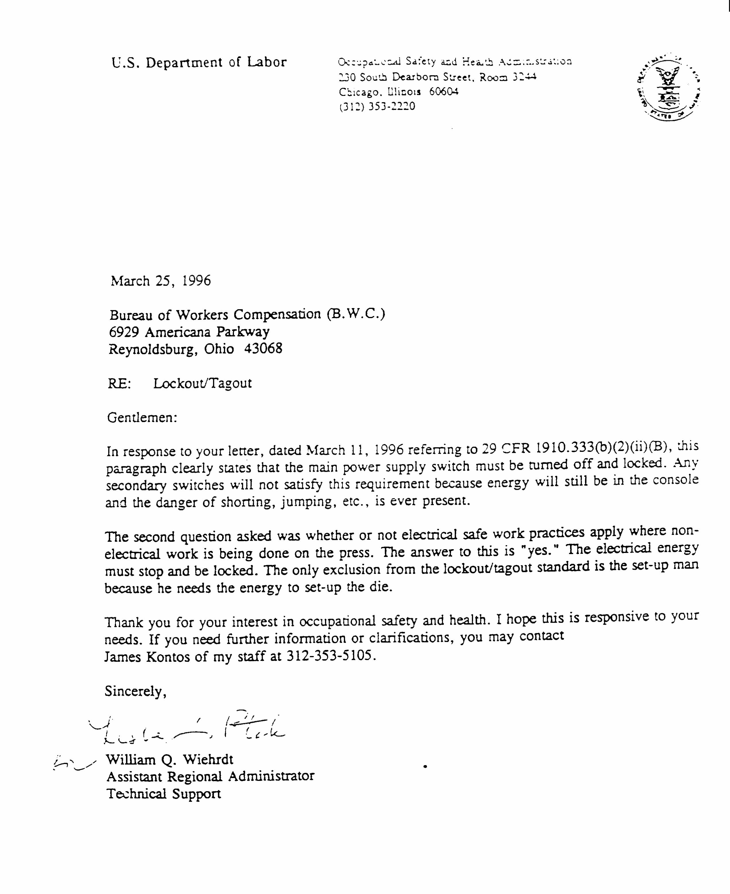

Regulations (Standards - 29 CFR) The control of hazardous energy (lockout/tagout). - 1910.147
OSHA Regulations (Standards - 29 CFR) - Table of Contents
l Standard Number: 1910.147 l Standard Title: The control of hazardous energy (lockout/tagout). l SubPart Number: J l SubPart Title: General Environmental Controls
(a)
Scope, application and purpose -
(a)(1)
Scope
(a)(1)(i)
This standard covers the servicing and maintenance of machines and equipment in which the unexpected energization or start up of the machines or equipment, or release of stored energy could cause injury to employees. This standard establishes minimum performance requirements for the control of such hazardous energy.
(a)(1)(ii)
This standard does not cover the following:
(a)(1)(ii)(A)
Construction, agriculture and maritime employment;
(a)(1)(ii)(B)
Interpretation(s)
Page 1 of 18The control of hazardous energy (lockout/tagout). - 1910.147
07/23/2001http://www.osha-slc.gov/OshStd_data/1910_0147.html

Installations under the exclusive control of electric utilities for the purpose of power generation, transmission and distribution, including related equipment for communication or metering; and
(a)(1)(ii)(C)
Exposure to electrical hazards from work on, near, or with conductors or equipment in electric utilization installations, which is covered by Subpart S of this part; and
..1910.147(a)(1)(ii)(D) (a)(1)(ii)(D)
Oil and gas well drilling and servicing.
(a)(2)
Application.
(a)(2)(i)
This standard applies to the control of energy during servicing and/or maintenance of machines and equipment.
(a)(2)(ii)
Normal production operations are not covered by this standard (See Subpart O of this Part). Servicing and/or maintenance which takes place during normal production operations is covered by this standard only if:
(a)(2)(ii)(A)
An employee is required to remove or bypass a guard or other safety device; or
(a)(2)(ii)(B)
An employee is required to place any part of his or her body into an area on a machine or piece of equipment where work is actually performed upon the material being processed (point of operation) or where an associated danger zone exists during a machine operating cycle.
Note: Exception to paragraph (a)(2)(ii): Minor tool changes and adjustments, and other minor servicing activities, which take place during normal production operations, are not covered by this standard if they are routine, repetitive, and integral to the use of the equipment for production, provided that the work is performed using alternative measures which provide effective protection (See Subpart O of this Part).
Page 2 of 18The control of hazardous energy (lockout/tagout). - 1910.147
07/23/2001http://www.osha-slc.gov/OshStd_data/1910_0147.html

(a)(2)(iii)
This standard does not apply to the following:
..1910.147(a)(2)(iii)(A) (a)(2)(iii)(A)
Work on cord and plug connected electric equipment for which exposure to the hazards of unexpected energization or start up of the equipment is controlled by the unplugging of the equipment from the energy source and by the plug being under the exclusive control of the employee performing the servicing or maintenance.
(a)(2)(iii)(B)
Hot tap operations involving transmission and distribution systems for substances such as gas, steam, water or petroleum products when they are performed on pressurized pipelines, provided that the employer demonstrates that-
(a)(2)(iii)(B)(1)
continuity of service is essential;
(a)(2)(iii)(B)(2)
shutdown of the system is impractical; and
(a)(2)(iii)(B)(3)
documented procedures are followed, and special equipment is used which will provide proven effective protection for employees.
(a)(3)
Purpose.
(a)(3)(i)
This section requires employers to establish a program and utilize procedures for affixing appropriate lockout devices or tagout devices to energy isolating devices, and to otherwise disable machines or equipment to prevent unexpected energization, start up or release of stored energy in order to prevent injury to employees.
(a)(3)(ii)
When other standards in this part require the use of lockout or tagout, they shall be used and supplemented by the procedural and training requirements of this section.
(b)
Page 3 of 18The control of hazardous energy (lockout/tagout). - 1910.147
07/23/2001http://www.osha-slc.gov/OshStd_data/1910_0147.html

Definitions applicable to this section.
Affected employee. An employee whose job requires him/her to operate or use a machine or equipment on which servicing or maintenance is being performed under lockout or tagout, or whose job requires him/her to work in an area in which such servicing or maintenance is being performed.
Authorized employee. A person who locks out or tags out machines or equipment in order to perform servicing or maintenance on that machine or equipment. An affected employee becomes an authorized employee when that employee's duties include performing servicing or maintenance covered under this section.
Capable of being locked out. An energy isolating device is capable of being locked out if it has a hasp or other means of attachment to which, or through which, a lock can be affixed, or it has a locking mechanism built into it. Other energy isolating devices are capable of being locked out, if lockout can be achieved without the need to dismantle, rebuild, or replace the energy isolating device or permanently alter its energy control capability.
Energized. Connected to an energy source or containing residual or stored energy.
Energy isolating device. A mechanical device that physically prevents the transmission or release of energy, including but not limited to the following: A manually operated electrical circuit breaker; a disconnect switch; a manually operated switch by which the conductors of a circuit can be disconnected from all ungrounded supply conductors, and, in addition, no pole can be operated independently; a line valve; a block; and any similar device used to block or isolate energy. Push buttons, selector switches and other control circuit type devices are not energy isolating devices.
Energy source. Any source of electrical, mechanical, hydraulic, pneumatic, chemical, thermal, or other energy.
Hot tap. A procedure used in the repair, maintenance and services activities which involves welding on a piece of equipment (pipelines, vessels or tanks) under pressure, in order to install connections or appurtenances. it is commonly used to replace or add sections of pipeline without the interruption of service for air, gas, water, steam, and petrochemical distribution systems.
Lockout. The placement of a lockout device on an energy isolating device, in accordance with an established procedure, ensuring that the energy isolating device and the equipment being controlled
Page 4 of 18The control of hazardous energy (lockout/tagout). - 1910.147
07/23/2001http://www.osha-slc.gov/OshStd_data/1910_0147.html

cannot be operated until the lockout device is removed.
Lockout device. A device that utilizes a positive means such as a lock, either key or combination type, to hold an energy isolating device in the safe position and prevent the energizing of a machine or equipment. Included are blank flanges and bolted slip blinds.
Normal production operations. The utilization of a machine or equipment to perform its intended production function.
Servicing and/or maintenance. Workplace activities such as constructing, installing, setting up, adjusting, inspecting, modifying, and maintaining and/or servicing machines or equipment. These activities include lubrication, cleaning or unjamming of machines or equipment and making adjustments or tool changes, where the employee may be exposed to the unexpected energization or startup of the equipment or release of hazardous energy.
Setting up. Any work performed to prepare a machine or equipment to perform its normal production operation.
Tagout. The placement of a tagout device on an energy isolating device, in accordance with an established procedure, to indicate that the energy isolating device and the equipment being controlled may not be operated until the tagout device is removed.
Tagout device. A prominent warning device, such as a tag and a means of attachment, which can be securely fastened to an energy isolating device in accordance with an established procedure, to indicate that the energy isolating device and the equipment being controlled may not be operated until the tagout device is removed.
..1910.147(c) (c)
General -
(c)(1)
Energy control program. The employer shall establish a program consisting of energy control procedures, employee training and periodic inspections to ensure that before any employee performs any servicing or maintenance on a machine or equipment where the unexpected energizing, startup or release of stored energy could occur and cause injury, the machine or equipment shall be isolated from the energy source and rendered inoperative.
(c)(2)
Lockout/tagout.
Page 5 of 18The control of hazardous energy (lockout/tagout). - 1910.147
07/23/2001http://www.osha-slc.gov/OshStd_data/1910_0147.html

(c)(2)(i)
If an energy isolating device is not capable of being locked out, the employer's energy control program under paragraph (c)(1) of this section shall utilize a tagout system.
(c)(2)(ii)
If an energy isolating device is capable of being locked out, the employer's energy control program under paragraph (c)(1) of this section shall utilize lockout, unless the employer can demonstrate that the utilization of a tagout system will provide full employee protection as set forth in paragraph (c)(3) of this section.
(c)(2)(iii)
After January 2, 1990, whenever replacement or major repair, renovation or modification of a machine or equipment is performed, and whenever new machines or equipment are installed, energy isolating devices for such machine or equipment shall be designed to accept a lockout device.
(c)(3)
Full employee protection.
(c)(3)(i)
When a tagout device is used on an energy isolating device which is capable of being locked out, the tagout device shall be attached at the same location that the lockout device would have been attached, and the employer shall demonstrate that the tagout program will provide a level of safety equivalent to that obtained by using a lockout program.
..1910.147(c)(3)(ii) (c)(3)(ii)
In demonstrating that a level of safety is achieved in the tagout program which is equivalent to the level of safety obtained by using a lockout program, the employer shall demonstrate full compliance with all tagout-related provisions of this standard together with such additional elements as are necessary to provide the equivalent safety available from the use of a lockout device. Additional means to be considered as part of the demonstration of full employee protection shall include the implementation of additional safety measures such as the removal of an isolating circuit element, blocking of a controlling switch, opening of an extra disconnecting device, or the removal of a valve handle to reduce the likelihood of inadvertent energization.
Page 6 of 18The control of hazardous energy (lockout/tagout). - 1910.147
07/23/2001http://www.osha-slc.gov/OshStd_data/1910_0147.html

(c)(4)
Energy control procedure.
(c)(4)(i)
Procedures shall be developed, documented and utilized for the control of potentially hazardous energy when employees are engaged in the activities covered by this section.
Note: Exception: The employer need not document the required procedure for a particular machine or equipment, when all of the following elements exist: (1) The machine or equipment has no potential for stored or residual energy or reaccumulation of stored energy after shut down which could endanger employees; (2) the machine or equipment has a single energy source which can be readily identified and isolated; (3) the isolation and locking out of that energy source will completely deenergize and deactivate the machine or equipment; (4) the machine or equipment is isolated from that energy source and locked out during servicing or maintenance; (5) a single lockout device will achieve a locker-out condition; (6) the lockout device is under the exclusive control of the authorized employee performing the servicing or maintenance; (7) the servicing or maintenance does not create hazards for other employees; and (8) the employer, in utilizing this exception, has had no accidents involving the unexpected activation or reenergization of the machine or equipment during servicing or maintenance.
(c)(4)(ii)
The procedures shall clearly and specifically outline the scope, purpose, authorization, rules, and techniques to be utilized for the control of hazardous energy, and the means to enforce compliance including, but not limited to, the following:
(c)(4)(ii)(A)
A specific statement of the intended use of the procedure;
(c)(4)(ii)(B)
Specific procedural steps for shutting down, isolating, blocking and securing machines or equipment to control hazardous energy;
(c)(4)(ii)(C)
Specific procedural steps for the placement, removal and transfer of lockout devices or tagout devices and the responsibility for them; and
..1910.147(c)(4)(ii)(D)
Page 7 of 18The control of hazardous energy (lockout/tagout). - 1910.147
07/23/2001http://www.osha-slc.gov/OshStd_data/1910_0147.html

(c)(4)(ii)(D)
Specific requirements for testing a machine or equipment to determine and verify the effectiveness of lockout devices, tagout devices, and other energy control measures.
(c)(5)
Protective materials and hardware.
(c)(5)(i)
Locks, tags, chains, wedges, key blocks, adapter pins, self-locking fasteners, or other hardware shall be provided by the employer for isolating, securing or blocking of machines or equipment from energy sources.
(c)(5)(ii)
Lockout devices and tagout devices shall be singularly identified; shall be the only devices(s) used for controlling energy; shall not be used for other purposes; and shall meet the following requirements:
(c)(5)(ii)(A)
Durable.
(c)(5)(ii)(A)(1)
Lockout and tagout devices shall be capable of withstanding the environment to which they are exposed for the maximum period of time that exposure is expected.
(c)(5)(ii)(A)(2)
Tagout devices shall be constructed and printed so that exposure to weather conditions or wet and damp locations will not cause the tag to deteriorate or the message on the tag to become illegible.
(c)(5)(ii)(A)(3)
Tags shall not deteriorate when used in corrosive environments such as areas where acid and alkali chemicals are handled and stored.
..1910.147(c)(5)(ii)(B) (c)(5)(ii)(B)
Standardized. Lockout and tagout devices shall be standardized within the facility in at least one of the following criteria: Color; shape; or size; and additionally, in the case of tagout devices, print
Page 8 of 18The control of hazardous energy (lockout/tagout). - 1910.147
07/23/2001http://www.osha-slc.gov/OshStd_data/1910_0147.html

and format shall be standardized.
(c)(5)(ii)(C)
Substantial -
(c)(5)(ii)(C)(1)
Lockout devices. Lockout devices shall be substantial enough to prevent removal without the use of excessive force or unusual techniques, such as with the use of bolt cutters or other metal cutting tools.
(c)(5)(ii)(C)(2)
Tagout devices. Tagout devices, including their means of attachment, shall be substantial enough to prevent inadvertent or accidental removal. Tagout device attachment means shall be of a non-reusable type, attachable by hand, self-locking, and non-releasable with a minimum unlocking strength of no less than 50 pounds and having the general design and basic characteristics of being at least equivalent to a one-piece, all environment-tolerant nylon cable tie.
(c)(5)(ii)(D)
Identifiable. Lockout devices and tagout devices shall indicate the identity of the employee applying the device(s).
(c)(5)(iii)
Tagout devices shall warn against hazardous conditions if the machine or equipment is energized and shall include a legend such as the following: Do Not Start. Do Not Open. Do Not Close. Do Not Energize. Do Not Operate.
..1910.147(c)(6) (c)(6)
Periodic inspection.
(c)(6)(i)
The employer shall conduct a periodic inspection of the energy control procedure at least annually to ensure that the procedure and the requirements of this standard are being followed.
(c)(6)(i)(A)
The periodic inspection shall be performed by an authorized employee other than the ones(s) utilizing the energy control procedure being inspected.
Page 9 of 18The control of hazardous energy (lockout/tagout). - 1910.147
07/23/2001http://www.osha-slc.gov/OshStd_data/1910_0147.html

(c)(6)(i)(B)
The periodic inspection shall be conducted to correct any deviations or inadequacies identified.
(c)(6)(i)(C)
Where lockout is used for energy control, the periodic inspection shall include a review, between the inspector and each authorized employee, of that employee's responsibilities under the energy control procedure being inspected.
(c)(6)(i)(D)
Where tagout is used for energy control, the periodic inspection shall include a review, between the inspector and each authorized and affected employee, of that employee's responsibilities under the energy control procedure being inspected, and the elements set forth in paragraph (c)(7)(ii) of this section.
..1910.147(c)(6)(ii) (c)(6)(ii)
The employer shall certify that the periodic inspections have been performed. The certification shall identify the machine or equipment on which the energy control procedure was being utilized, the date of the inspection, the employees included in the inspection, and the person performing the inspection.
(c)(7)
Training and communication.
(c)(7)(i)
The employer shall provide training to ensure that the purpose and function of the energy control program are understood by employees and that the knowledge and skills required for the safe application, usage, and removal of the energy controls are acquired by employees. The training shall include the following:
(c)(7)(i)(A)
Each authorized employee shall receive training in the recognition of applicable hazardous energy sources, the type and magnitude of the energy available in the workplace, and the methods and means necessary for energy isolation and control.
(c)(7)(i)(B)
Each affected employee shall be instructed in the purpose and use of the energy control procedure.
Page 10 of 18The control of hazardous energy (lockout/tagout). - 1910.147
07/23/2001http://www.osha-slc.gov/OshStd_data/1910_0147.html

(c)(7)(i)(C)
All other employees whose work operations are or may be in an area where energy control procedures may be utilized, shall be instructed about the procedure, and about the prohibition relating to attempts to restart or reenergize machines or equipment which are locked out or tagged out.
(c)(7)(ii)
When tagout systems are used, employees shall also be trained in the following limitations of tags:
..1910.147(c)(7)(ii)(A) (c)(7)(ii)(A)
Tags are essentially warning devices affixed to energy isolating devices, and do not provide the physical restraint on those devices that is provided by a lock.
(c)(7)(ii)(B)
When a tag is attached to an energy isolating means, it is not to be removed without authorization of the authorized person responsible for it, and it is never to be bypassed, ignored, or otherwise defeated.
(c)(7)(ii)(C)
Tags must be legible and understandable by all authorized employees, affected employees, and all other employees whose work operations are or may be in the area, in order to be effective.
(c)(7)(ii)(D)
Tags and their means of attachment must be made of materials which will withstand the environmental conditions encountered in the workplace.
(c)(7)(ii)(E)
Tags may evoke a false sense of security, and their meaning needs to be understood as part of the overall energy control program.
(c)(7)(ii)(F)
Tags must be securely attached to energy isolating devices so that they cannot be inadvertently or accidentally detached during use.
(c)(7)(iii)
Employee retraining.
Page 11 of 18The control of hazardous energy (lockout/tagout). - 1910.147
07/23/2001http://www.osha-slc.gov/OshStd_data/1910_0147.html

..1910.147(c)(7)(iii)(A) (c)(7)(iii)(A)
Retraining shall be provided for all authorized and affected employees whenever there is a change in their job assignments, a change in machines, equipment or processes that present a new hazard, or when there is a change in the energy control procedures.
(c)(7)(iii)(B)
Additional retraining shall also be conducted whenever a periodic inspection under paragraph (c)(6) of this section reveals, or whenever the employer has reason to believe that there are deviations from or inadequacies in the employee's knowledge or use of the energy control procedures.
(c)(7)(iii)(C)
The retraining shall reestablish employee proficiency and introduce new or revised control methods and procedures, as necessary.
(c)(7)(iv)
The employer shall certify that employee training has been accomplished and is being kept up to date. The certification shall contain each employee's name and dates of training.
(c)(8)
Energy isolation. Lockout or tagout shall be performed only by the authorized employees who are performing the servicing or maintenance.
(c)(9)
Notification of employees. Affected employees shall be notified by the employer or authorized employee of the application and removal of lockout devices or tagout devices. Notification shall be given before the controls are applied, and after they are removed from the machine or equipment.
..1910.147(d) (d)
Application of control. The established procedures for the application of energy control (the lockout or tagout procedures) shall cover the following elements and actions and shall be done in the following sequence:
Page 12 of 18The control of hazardous energy (lockout/tagout). - 1910.147
07/23/2001http://www.osha-slc.gov/OshStd_data/1910_0147.html

(d)(1)
Preparation for shutdown. Before an authorized or affected employee turns off a machine or equipment, the authorized employee shall have knowledge of the type and magnitude of the energy, the hazards of the energy to be controlled, and the method or means to control the energy.
(d)(2)
Machine or equipment shutdown. The machine or equipment shall be turned off or shut down using the procedures established for the machine or equipment. An orderly shutdown must be utilized to avoid any additional or increased hazard(s) to employees as a result of the equipment stoppage.
(d)(3)
Machine or equipment isolation. All energy isolating devices that are needed to control the energy to the machine or equipment shall be physically located and operated in such a manner as to isolate the machine or equipment from the energy source(s).
(d)(4)
Lockout or tagout device application.
(d)(4)(i)
Lockout or tagout devices shall be affixed to each energy isolating device by authorized employees.
..1910.147(d)(4)(ii) (d)(4)(ii)
Lockout devices, where used, shall be affixed in a manner to that will hold the energy isolating devices in a "safe" or "off" position.
(d)(4)(iii)
Tagout devices, where used, shall be affixed in such a manner as will clearly indicate that the operation or movement of energy isolating devices from the "safe" or "off" position is prohibited.
(d)(4)(iii)(A)
Where tagout devices are used with energy isolating devices designed with the capability of being locked, the tag attachment shall be fastened at the same point at which the lock would have been attached.
(d)(4)(iii)(B)
Page 13 of 18The control of hazardous energy (lockout/tagout). - 1910.147
07/23/2001http://www.osha-slc.gov/OshStd_data/1910_0147.html

Where a tag cannot be affixed directly to the energy isolating device, the tag shall be located as close as safely possible to the device, in a position that will be immediately obvious to anyone attempting to operate the device.
(d)(5)
Stored energy.
(d)(5)(i)
Following the application of lockout or tagout devices to energy isolating devices, all potentially hazardous stored or residual energy shall be relieved, disconnected, restrained, and otherwise rendered safe.
..1910.147(d)(5)(ii) (d)(5)(ii)
If there is a possibility of reaccumulation of stored energy to a hazardous level, verification of isolation shall be continued until the servicing or maintenance is completed, or until the possibility of such accumulation no longer exists.
(d)(6)
Verification of isolation. Prior to starting work on machines or equipment that have been locked out or tagged out, the authorized employee shall verify that isolation and deenergization of the machine or equipment have been accomplished.
(e)
Release from lockout or tagout. Before lockout or tagout devices are removed and energy is restored to the machine or equipment, procedures shall be followed and actions taken by the authorized employee(s) to ensure the following:
(e)(1)
The machine or equipment. The work area shall be inspected to ensure that nonessential items have been removed and to ensure that machine or equipment components are operationally intact.
(e)(2)
Employees.
(e)(2)(i)
The work area shall be checked to ensure that all employees have been safely positioned or removed.
Page 14 of 18The control of hazardous energy (lockout/tagout). - 1910.147
07/23/2001http://www.osha-slc.gov/OshStd_data/1910_0147.html

(e)(2)(ii)
After lockout or tagout devices have been removed and before a machine or equipment is started, affected employees shall be notified that the lockout or tagout device(s) have been removed.
(e)(3)
Lockout or tagout devices removal. Each lockout or tagout device shall be removed from each energy isolating device by the employee who applied the device. Exception to paragraph (e)(3): When the authorized employee who applied the lockout or tagout device is not available to remove it, that device may be removed under the direction of the employer, provided that specific procedures and training for such removal have been developed, documented and incorporated into the employer's energy control program. The employer shall demonstrate that the specific procedure provides equivalent safety to the removal of the device by the authorized employee who applied it. The specific procedure shall include at least the following elements:
(e)(3)(i)
Verification by the employer that the authorized employee who applied the device is not at the facility:
(e)(3)(ii)
Making all reasonable efforts to contact the authorized employee to inform him/her that his/her lockout or tagout device has been removed; and
(e)(3)(iii)
Ensuring that the authorized employee has this knowledge before he/she resumes work at that facility.
..1910.147(f) (f)
Additional requirements.
(f)(1)
Testing or positioning of machines, equipment or components thereof. In situations in which lockout or tagout devices must be temporarily removed from the energy isolating device and the machine or equipment energized to test or position the machine, equipment or component thereof, the following sequence of actions shall be followed:
Page 15 of 18The control of hazardous energy (lockout/tagout). - 1910.147
07/23/2001http://www.osha-slc.gov/OshStd_data/1910_0147.html

(f)(1)(i)
Clear the machine or equipment of tools and materials in accordance with paragraph (e)(1) of this section;
(f)(1)(ii)
Remove employees from the machine or equipment area in accordance with paragraph (e)(2) of this section;
(f)(1)(iii)
Remove the lockout or tagout devices as specified in paragraph (e)(3) of this section;
(f)(1)(iv)
Energize and proceed with testing or positioning;
(f)(1)(v)
Deenergize all systems and reapply energy control measures in accordance with paragraph (d) of this section to continue the servicing and/or maintenance.
(f)(2)
Outside personnel (contractors, etc.).
(f)(2)(i)
Whenever outside servicing personnel are to be engaged in activities covered by the scope and application of this standard, the on-site employer and the outside employer shall inform each other of their respective lockout or tagout procedures.
..1910.147(f)(2)(ii) (f)(2)(ii)
The on-site employer shall ensure that his/her employees understand and comply with the restrictions and prohibitions of the outside employer's energy control program.
(f)(3)
Group lockout or tagout.
(f)(3)(i)
When servicing and/or maintenance is performed by a crew, craft, department or other group, they shall utilize a procedure which affords the employees a level of protection equivalent to that
Page 16 of 18The control of hazardous energy (lockout/tagout). - 1910.147
07/23/2001http://www.osha-slc.gov/OshStd_data/1910_0147.html

provided by the implementation of a personal lockout or tagout device.
(f)(3)(ii)
Group lockout or tagout devices shall be used in accordance with the procedures required by paragraph (c)(4) of this section including, but not necessarily limited to, the following specific requirements:
(f)(3)(ii)(A)
Primary responsibility is vested in an authorized employee for a set number of employees working under the protection of a group lockout or tagout device (such as an operations lock);
(f)(3)(ii)(B)
Provision for the authorized employee to ascertain the exposure status of individual group members with regard to the lockout or tagout of the machine or equipment and
(f)(3)(ii)(C)
When more than one crew, craft, department, etc. is involved, assignment of overall job-associated lockout or tagout control responsibility to an authorized employee designated to coordinate affected work forces and ensure continuity of protection; and
..1910.147(f)(3)(ii)(D) (f)(3)(ii)(D)
Each authorized employee shall affix a personal lockout or tagout device to the group lockout device, group lockbox, or comparable mechanism when he or she begins work, and shall remove those devices when he or she stops working on the machine or equipment being serviced or maintained.
(f)(4)
Shift or personnel changes. Specific procedures shall be utilized during shift or personnel changes to ensure the continuity of lockout or tagout protection, including provision for the orderly transfer of lockout or tagout device protection between off-going and oncoming employees, to minimize exposure to hazards from the unexpected energization or start-up of the machine or equipment, or the release of stored energy.
Note: The following appendix to §1910.147 services as a non-mandatory guideline to assist employers and employees in complying with the requirements of this section, as well as to
Page 17 of 18The control of hazardous energy (lockout/tagout). - 1910.147
07/23/2001http://www.osha-slc.gov/OshStd_data/1910_0147.html

provide other helpful information. Nothing in the appendix adds to or detracts from any of the requirements of this section.
[54 FR 36687, Sept. 1, 1989, as amended at 54 FR 42498, Oct. 17, 1989; 55 FR 38685, 38686, Sept. 20, 1990; 61 FR 5507, Feb. 13, 1996]
OSHA Regulations (Standards - 29 CFR) - Table of Contents
Page 18 of 18The control of hazardous energy (lockout/tagout). - 1910.147
07/23/2001http://www.osha-slc.gov/OshStd_data/1910_0147.html

Regulations (Standards - 29 CFR) Typical minimal lockout procedures - 1910.147AppA
OSHA Regulations (Standards - 29 CFR) - Table of Contents
l Standard Number: 1910.147AppA l Standard Title: Typical minimal lockout procedures l SubPart Number: J l SubPart Title: None
General
The following simple lockout procedure is provided to assist employers in developing their procedures so they meet the requirements of this standard. When the energy isolating devices are not lockable, tagout may be used, provided the employer complies with the provisions of the standard which require additional training and more rigorous periodic inspections. When tagout is used and the energy isolating devices are lockable, the employer must provide full employee protection (see paragraph (c)(3)) and additional training and more rigorous periodic inspections are required. For more complex systems, more comprehensive procedures may need to be developed, documented, and utilized.
Lockout Procedure Lockout Procedure for _____________________________________________________________________ (Name of Company for single procedure or identification of equipment if multiple procedures are used). Purpose
This procedure establishes the minimum requirements for the
Page 1 of 4Typical minimal lockout procedures - 1910.147AppA
07/23/2001http://www.osha-slc.gov/OshStd_data/1910_0147_APP_A.html

lockout of energy isolating devices whenever maintenance or servicing is done on machines or equipment. It shall be used to ensure that the machine or equipment is stopped, isolated from all potentially hazardous energy sources and locked out before employees perform any servicing or maintenance where the unexpected energization or start-up of the machine or equipment or release of stored energy could cause injury.
Compliance With This Program
All employees are required to comply with the restrictions and limitations imposed upon them during the use of lockout. The authorized employees are required to perform the lockout in accordance with this procedure. All employees, upon observing a machine or piece of equipment which is locked out to perform servicing or maintenance shall not attempt to start, energize, or use that machine or equipment.
_____________________________________________________________________ Type of compliance enforcement to be taken for violation of the above. Sequence of Lockout
(1) Notify all affected employees that servicing or maintenance is required on a machine or equipment and that the machine or equipment must be shut down and locked out to perform the servicing or maintenance.
___________________________________________________________________ Name(s)/Job Title(s) of affected employees and how to notify.
(2) The authorized employee shall refer to the company procedure to identify the type and magnitude of the energy that the machine or equipment utilizes, shall understand the hazards of the energy, and shall know the methods to control the energy.
_____________________________________________________________________ Type(s) and magnitude(s) of energy, its hazards and the methods to control the energy.
(3) If the machine or equipment is operating, shut it down by the normal stopping procedure (depress the stop button, open switch, close valve, etc.).
Page 2 of 4Typical minimal lockout procedures - 1910.147AppA
07/23/2001http://www.osha-slc.gov/OshStd_data/1910_0147_APP_A.html

_____________________________________________________________________ Type(s) and location(s) of machine or equipment operating controls.
(4) De-activate the energy isolating device(s) so that the machine or equipment is isolated from the energy source(s).
_____________________________________________________________________ Type(s) and location(s) of energy isolating devices.
(5) Lock out the energy isolating device(s) with assigned individual lock(s).
(6) Stored or residual energy (such as that in capacitors, springs, elevated machine members, rotating flywheels, hydraulic systems, and air, gas, steam, or water pressure, etc.) must be dissipated or restrained by methods such as grounding, repositioning, blocking, bleeding down, etc.
_____________________________________________________________________ Type(s) of stored energy - methods to dissipate or restrain.
(7) Ensure that the equipment is disconnected from the energy source(s) by first checking that no personnel are exposed, then verify the isolation of the equipment by operating the push button or other normal operating control(s) or by testing to make certain the equipment will not operate.
Caution: Return operating control(s) to neutral or "off" position after verifying the isolation of the equipment.
_____________________________________________________________________ Method of verifying the isolation of the equipment.
(8) The machine or equipment is now locked out.
"Restoring Equipment to Service." When the servicing or maintenance is completed and the machine or equipment is ready to return to normal operating condition, the following steps shall be taken.
(1) Check the machine or equipment and the immediate area around the machine to ensure that nonessential items have been
Page 3 of 4Typical minimal lockout procedures - 1910.147AppA
07/23/2001http://www.osha-slc.gov/OshStd_data/1910_0147_APP_A.html

removed and that the machine or equipment components are operationally intact.
(2) Check the work area to ensure that all employees have been safely positioned or removed from the area.
(3) Verify that the controls are in neutral.
(4) Remove the lockout devices and reenergize the machine or equipment. Note: The removal of some forms of blocking may require reenergization of of the machine before safe removal.
(5) Notify affected employees that the servicing or maintenance is completed and the machine or equipment is ready for used.
[54 FR 36687, Sept. 1, 1989 as amended at 54 FR 42498, Oct. 17, 1989; 55 FR 38685, Sept. 20, 1990; 61 FR 5507, Feb. 13, 1996]
OSHA Regulations (Standards - 29 CFR) - Table of Contents
Page 4 of 4Typical minimal lockout procedures - 1910.147AppA
07/23/2001http://www.osha-slc.gov/OshStd_data/1910_0147_APP_A.html

Die Setting


Section 9 - 1
Die setting
Setting Up and Removing Power Press Dies
1. Power Press Dies vary in weight from a few pounds to several thousand pounds. Handling,setting up, and removing these dies can be hazardous unless proper equipment and methodsare used. These operations should be entrusted only to experienced personnel who havebeen instructed in detail about safe procedures used in setting and removing power pressdies safely.
Hazards
2. The following are some injuries that may result when setting or removing power press dies:• Strains and hernias can result from excessive lifting and pushing or pulling using
improper handling techniques;• Foot injuries can occur when dies slip off trucks, benches bolster plates, or storage
shelves and strike the foot;• Crushing injuries can result when parts of the body are placed between the dies and
press or pinch points and intended movement of the slide or die occurs;• Lacerations can be caused by wrenches slipping off worn nuts or stud bolts and
also from using improper tools;• Eye injuries can be caused by flying pieces of shattered dies or material due to
improper die setting.
Transferring dies safely
3. All upper and lower die shoes should be fastened together to prevent them from separatingunexpectedly.
4. Light-weight dies can generally be handled without mechanical lifting apparatus.
5. Safe handling of medium-size dies requires the use of eyebolts in addition to the die trucks.Regular or plain eyebolts should not be used because of the likelihood of eyebolt failure dueto bending. The fully threaded, shoulder type is recommended because of its ability to carrya greater load safely and must be properly seated (see Figure 1).


Section 9 - 4
8. For moving heavy-weight dies, special die-handling power trucks are recommended. Thesetrucks should be equipped with special equipment for pushing or pulling the die, such aspower winches, roller tables and hydraulic or pneumatic clamps. When transferring dies,place the die truck close to the shelf or press and then adjust the table to the same height asthe shelf or bolster plate. Secure the truck by chocking the wheels or locking the brake orsome other method to prevent truck movement. Then move the die off the die table ontothe bolster plate or shelf. It is recommended that die stops or other means be used toprevent losing control of the die being used when setting or removing dies in inclinedpresses. To bring a die onto a truck , engage a hook in the die so it cannot slip and exert asteady pull, do not jerk or tug on the hook. Where listing is necessary to make the transfer,use a hoist; never lift the die higher than is necessary for minimum clearance. At no timeshould an employee have his/her hands, feet or other part of his body underneath asuspended load.
Setting up dies
9. The following safe method for setting up and removing power press dies should be followedfor all presses. Check die specifications against the following requirements:
a. Clear away all stock, containers, tools and other tripping hazards from the work area. Bring the slide down to its lowest position.
b. Disconnect or shut off the power and lock the electrical disconnect switch.
c. Measure the clearance height between the bottom of the slide and bolster plate; this distance (shut height) should be slightly greater than, or at least equal to, the height of the closed die; if not, adjust as required.
d. Raise the slide and insert the safety blocks and leave the slide at the top of stroke. Follow normal procedure to re-engage power is necessary. Safety blocks must be used whenever dies are being adjusted or repaired. Blocks on part-revolution presses should be equipped with an electric interlocking plug, which must be removed from its circuit receptacle before the block can be placed in the die area. On full revolution presses, lock out the drive motor and insert the safety block.
10. Clean the bolster plate and check the die to make sure it does not contain any chips, tools,or finished parts. Then transfer the die to the press.
11. Line up the die in the correct operating position, and remove the die safety block fromunder the slide. Then, carefully lower the slide until it fits firmly against the top die. Tightenall bolts and clamps necessary to secure the top half of the die to the slide.

Section 9 - 5
12. Position the lower half of the die and bolt and clamp it to the bolster plate. Thread the boltinto the bolster plate to a depth of 1 1/2 time the diameter of the bolt used to provide theproper holding power. Bolting the die shoe to the bolster produces the most secure diesetup. If clamps must be used, their outer ends should be blocked up slightly higher thanthe die surface on which their inner ends will rest. Clamps should be on minimum lengthand should not interfere with the safe operation of the press. Clamp-fastening bolts shouldbe closer to the die than to the block end of the clamp.
13. For forming or drawing operations, adjust the slide down the almost its proper depth. Fora piece or trim die, raise the slide slightly, so that the punch will not shear when the slide iscycled.
a. Raise the slide to its highest point and block it in this position.b. Make sure the die is free of all foreign material.c. Install point-of-operation safeguarding, and check for adjustment and operation.d. Check guide posts and engagement points, and if separated by more than 1/4 inch, must be protected and treated as a point-of-operation hazard.e. Reconnect the power. Be sure to check that operating controls and the point- of-operation safeguarding are in proper working order. Operate the press several times, using the proper material. Make any necessary adjustments only after shutting off the power and blocking up the slide with safety blocks.f. After completing the adjustments, remove the safety blocks, turn on the power and again try several operations on the press. If satisfactory, the operator should be given instructions by an authorized person who should observe his methods for a sufficient period of time to insure that the operator is thoroughly familiar with the operation to be performed.
Removing dies
14. The removal of dies from a press should be done with the same care used in setting them up, although modifications may be necessary in special cases. The following is a recommended procedure:
a. Clear away all stock, containers, tools, and other tripping hazards from the work area.b. Close the die by lowering slide to bottom of stroke. Shut off power and block out disconnect switch. Full-revolution clutch presses may require the use of a turnover bar to close the die manually. Before inching or jogging the press, be sure no one is in a hazardous area.c. CAUTION: Hazards can be encountered if die cushions are not
de-energized properly. Care must be taken to make sure that all air pressure is

Section 9 - 6
removed from cushions. The large cylinder area common in die cushions creates great forces with relatively low air pressures. Because of the location of die cushions it is common that chips, flashings, etc., can cause them to appear inoperative, thus creating a serious hazard if the situation is not properly assessed. If the die is operated with an air cushion, shut off the air supply and open the release valve to permit the pins to go down. Also shut off the air supply to the air ejection system used on the die if one was in use.d. Loosen and remove all bolts and clamps bolting the die to the slide and bolster plate. Plate all bolts, nuts, and clamps on a bench or special place on the die truck as soon as they are removed.e. Make certain that the die is loose and that all bolts, nuts, clamps, and otherf. Slowly raise the slide (manually on small press, and by jogging or inching under power on large presses), making sure that the die does not hand onto the slide. Close the die by lowering slide to bottom of stroke. Shut off and lock out disconnect switch.g. Full revolution clutch presses may require the use of a turnover bar to close die manually. Raise the slide to top to stroke, shut off the power, and lock the electrical disconnect switch, and insert safety blocks.h. Fasten both halves of dies together for handling.I. Transfer the die from the press to storage


Section 9 - 10
Mechanical Power Presses - Die Setting Safety Procedures
MACHINE # ____________DEPARTMENT __________________ DATE _________
The Die Setter Must Be Properly Trained in Die Setting Techniques and Safety.
1. Lock off the main power to the press with a lock. The die setter should retain the key until thepress is again ready to be operated. If more than one person is working on the press; then thatnumber of locks should be used to lock off power to the press and each person working on thepress should have separate and different keys.
2. Safeguards should be clear of any danger that may arise during the die setting procedure, i.e.,
forklift trucks, etc. 3. Insert safety blocks. Make sure the flywheel has come to a complete rest. 4. Clean the bolster plate, dies and press surfaces before installing dies. Misalignment caused by
dirt, chips of metal or other foreign materials could result in injury to operator or damage topress and dies.
5. Make sure the floor and general press area are clean and free of material to allow for free
movement. 6. Clamp bolster plate firmly to press. Be sure bolts are in good condition so that constant
vibration will not allow plate to move out of position. 7. Do not install worn or damaged dies. Use the proper die to the press size to prevent
overloading, which could cause damage to press, dies or injury to operator. 8. All dies must be securely fastened to truck before moving. 9. When a new die set is being placed in a press, the crank should be straight down, the drive
motor shut off and the slide adjustment high enough to properly clear the die set. 10. Clamp dies to bolster plate and slide with enough clamps and the proper size clamps to hold
dies firmly in position. 11. Before inching or cycling the slide , make a visual press inspection of the press area to make
certain the press is ready to run and employees or visitors are free from danger.

Section 9 - 11
12. Before cycling the press, perform all necessary adjustments during and after die installation. Besure slide height adjusting shaft clamps are tight. If optional slide height lock assembly isfurnished, make certain lock nut is up tight and locking clamp crews are secured.
13. Reset counterbalance air pressure to compensate for weight of upper die. 14. Reposition the safeguard(s) and make certain it is properly secured to press, is properly
adjusted to OSHA’s safe-distance requirements or Table 0.10, or both, if appropriate. Makesure interlocks, if provided, are operating and the safeguard is properly operating.
15. Before turning the press over to the operator, make certain the operator has been properly
trained to operate the press and is aware of safety procedures for the press operator. 16. Observe press operation for a sufficient length of time to determine that the press is working
properly. 17. Before leaving the press area, make sure all tools, bolts or other obstructions in or near the
press are taken or removed. NOTE: Use extra care in setting, coining, embossing or forming dies. These dies are
of the closed type and do not provide relief for flow or displacement of excess material. Setting these dies too close or bottoming a die will cause a rapid increase in pressure required to carry the crankshaft beyond bottom dead center and will increase the possibility of seriously damaging the press and dies
or injury to the operator. I, the undersigned, certify that I have followed the above procedures when setting dies in the
machine described above. I further certify to the best of my ability, the safeguard is in properworking order, as is the press and the safeguard is adjusted to the OSHA 1910.217 standards.
Signature ______________________________ Date _____________ Time: ________ (Name)

Section 9 - 12
DIE SETTING
Name of Press ____________________________________ Stroke ___________________
Serial # _______________________________ Press # __________________________
Tonnage ________________________
YES NO_____ _____ 1. Die storage rack_____ _____ 2. Die markings-tonnage _____ Total Weight _____ Upper weight __________ _____ 3. Forklift_____ _____ 4. Cranes_____ _____ 5. Slings_____ _____ 6. Cart_____ _____ 7. Removing stuck hand tool_____ _____ 8. Scrap hand tool_____ _____ 9. Roll feed_____ _____ 10. Die fastening: Bolts size _____ Nuts __________ _____ 11. Tools for set-up_____ _____ 12. Turnover bar_____ _____ 13. Die stops_____ _____ 14. Safety blocks_____ _____ 15. Lubricating hand brushes _____ Swabs _____ Automatic __________ _____ 16. Hand spray __________ _____ 17. Bolster plate cleaned_____ _____ 18. Measuring the die __________ _____ 19. Inch, turnover bar or job ram to bottom of stroke (more than one set up person)_____ _____ 20. Measuring the opening __________ _____ 21. Look out set die in press_____ _____ 22. Secure upper and lower die_____ _____ 23. Kiss blocks, die stop blocks, thickness_____ _____ 24. Air counterbalance_____ _____ 25. Air switches_____ _____ 26. Counterbalance data plate_____ _____ 27. Regulators_____ _____ 28. Tonnage Meter_____ _____ 29. Return all guard


Section 9 - 14
DIE SETTING QUIZ
(CIRCLE ONE)
1. A PART REVOLUTION CLUTCH PRESS CANNOT BE STOPPED T FDURING THE CYCLE.
2. A FULL REVOLUTION CLUTCH PRESS CAN BE STOPPED AT T FANY POINT DURING THE CYCLE.
3. DISCONNECT SWITCHES CAPABLE OF BEING LOCKED ONLY T FIN THE “OFF” POSITION AND LOCKOUT/TAGOUT ONLYAPPLIES TO PART REVOLUTION PRESS.
4. CONTROL RELIABILITY AND BRAKE MONITORING IS T FREQUIRED WHEN THE OPERATOR IS PLACING HIS/HERHAND(S) INTO THE POINT OF OPERATION ON A PARTREVOLUTION CLUTCH PRESS.
5. WHEN SETTING UP A PRESS AND THE SELECTION IS IN INCH T FMODE, THE SET-UP PERSON CAN PUT HIS/HER HANDS IN THEDIE AS LONG AS THE PRESS IS LOCKED OUT.
6. SET-UP PERSONNEL ARE NOT RESPONSIBLE FOR ADJUSTING T FGUARDS OR DEVICES.
7. HAND TOOLS MUST BE USED TO REMOVE SCRAP OR FREE T FSTUCK PARTS.
8. IT IS A FEDERAL REQUIREMENT FOR EMPLOYERS TO T FINSPECT AND MAINTAIN A CERTIFICATION FOR ALL PRESSES,ONLY IF THERE HAS BEEN AN ACCIDENT ON THAT PRESS.
9. PROPER RELINING OF ASBESTOS BRAKES AND CLUTCHES T FINVOLVES WET METHODS FOR DUST REMOVAL ANDVACUUMING WITH HEPA VACUUM RATHER THAN BLOWINGOUT THE DUST WITH COMPRESSED AIR.
10. DIE BLOCKS SHALL BE PROVIDED AND USED WHENEVER T FDIES ARE BEING MAINTAINED OR REPAIRED AND LOCKOUTTAGOUT DOES NOT APPLY.
11. WILL THE DIE FIT IN THE PRESS IF THE RAM IS AT TOP T FSTROKE, AND THE DIE IS 23.25” IN HEIGHT AND THE OPENINGIS 33” WITH A 10” STROKE?
12. WOULD THE DIE FIT IF THE RAM IS AT THE TOP OF THE T F STROKE, THE DIE IS 23” IN HEIGHT, AND THE STROKE IS7” WITH A SHUT HEIGHT OPENING OF 31” ?
13. IF YOU HAVE NO STOP BLOCKS, YOU CAN JUST GUESS AT T FTHE THICKNESS OF THE STOCK TO ADJUST THE RAM

Section 9 - 15
14. IN GENERAL, THE BEST WAY TO PROTECT WORKERS USING POWER PRESSES IS:
A. A PERMANENT FIXED GUARD
B. USING HAND TOOLS
C. USING THE PROPER SAFETY DISTANCE
15. THE AREA OF THE PRESS, WHERE MATERIAL IS POSITIONED AND WORK ISPERFORMED, IS CALLED:
A. THE BOLSTER PLATE
B. THE DIE
C. THE POINT OF OPERATION
16. AUTOMATIC DEACTIVATION OF THE CLUTCH/BRAKE CONTROL, IN THE EVENT OF AIR PRESSURE FAILURE, IS INITIATED BY:
A. AN AIR PRESSURE SWITCH
B. A LARGER AIR LINE
C. A BRAKE MONITOR
17. A SIGNIFICANT INCREASE IN STOPPING TIME, MEASURED IN MILLISECONDS OR EXCESSIVE TOP STOP OVER RUN, SHOULD BE DETECTED BY:
A. CONTROL RELIABILITY MECHANISMS
B. AIR COUNTERBALANCE SYSTEMS
C. BRAKE MONITOR
18. IF YOU HAVE KISS BLOCKS (SAFETY BLOCKS) AND YOU HAVE THE TOOL.ROOM GRINDOFF THIRTY THOUSANDTHS OF AN INCH OFF OF A PUNCH. HOW MUCH WOULD YOU HAVE TOGRIND OFF OF THE KISS BLOCK?
A. .030”
B. .0035”
C. .0040”
19. THE SHUT HEIGHT IS MEASURED FROM:
A. TOP STROKE
B. BOTTOM STROKE
C. MID STROKE

Section 9 - 16
20. WHERE WOULD YOU FIND THE INFORMATION FOR THE DIE, I.E. TONNAGE, WEIGHT OF DIE SET AND UPPER DIE?
A. SUPERVISOR
B. DIE RECORDS
C. STAMPED ON DIE
21. IF THE DIE IS 13” TALL AND THE RAM IS AT THE BOTTOM OF THE STROKE AND THEOPENING IS 23”, HOW FAR WOULD YOU HAVE TO ADJUST THE SHUT HEIGHT?
A. 10”
B. 13”
22. IF YOU HAVE A SHUT HEIGHT OF 30 INCHES AT THE BOTTOM OF THE STROKE, ANDYOU HAVE A DIE THAT IS 23 INCHES. HOW MUCH ADJUSTMENT ON THE PITMAN IS NEEDED TO CLOSE DOWN ON THE DIE ?
A. 9”
B. 7”
C. 5.5”
23. SET-UP PERSON SHOULD ALWAYS CHECK THE SHUT HEIGHT AT THE
A. BOTTOM OF THE STROKE
B. MIDDLE OF THE STROKE
C. ON THE UP STROKE

Inspections


Section 10 - 1
MECHANICAL PRESSES
Preventive Press Maintenance, By: Robert Soman
Previous installments in this article on mechanical press maintenance focused on specific areasincluding tie rods, clutches, etc. This final installment discusses things such as belt tension andthe importance of counterbalance adjustment. Too often, these “little” matters are a source ofdowntime and damage simply because they are taken for granted.
Torsional Overload
When a press equipped with a friction clutch is overloaded torsionally, normally the clutch willslip. Sometimes this occurs near the bottom of the stroke, especially during the die setting. Ifthis happens the press will “stick-on-bottom” and it will be difficult to engage the clutch (withoutslipping) to get the press off bottom. This condition results because the press frame is strained,usually beyond the rated capacity of the press.
If this condition occurs it is important to establish whether the press is on the downstroke,upstroke, or on bottom dead center, so that the proper direction of slide movement to clear thejam can be determined. If the press is not equipped with a slide position indicator, observationof the crankshaft keyway may help, as this keyway is usually located down when the stroke isdown.
If it is not possible to determine the position of the slide visually, it may be possible to do so byobserving the motion of a dial indicator when the press id instantaneously jogged.
Having determined the direction the slide must move, the press should be jogged in this directionunder elevated clutch pressure, usually not to exceed 100 psi. If the press is to be reversed,and it is not equipped with a reversing starter, the motor leads must be reversed temporarily.
If the press cannot be “unstuck” using this method and if it fortuitously is of tie rod construction,the tie rods can be relaxed. If the press is of solid frame or gap frame construction, the problemis more serious. Dry ice can be used on the dies. And as a last resort, some part of the diemay have to be sacrificed by burning to relieve the press.
Capacity Overload
A press can also be overloaded by exceeding its energy capacity. This results in the flywheelslowing down either during one press stroke, or progressively. If the flywheel slows down toomuch during a single press stroke, the only remedy is to increase the flywheel energy. Thismeans either using a larger flywheel or speeding up the existing flywheel. A larger motor will beof a little help.
Section 10 - 2
Sometimes the press configuration will allow for a ring to be shrunk on the O.D. of the flywheelto increase its energy. This is especially true of overhung flywheels such as those found on non-geared presses, and also on presses having quill-mounted flywheels. In either case, the motormust be checked to be sure that it has sufficient torque to bring the larger flywheel back tosynchronous speed in the available time.
It is not often practical to increased flywheel energy by increasing press speed with a pulleychange, although a small increase in speed is significant because energy available is a function ofthe square of its speed. In the first place, work requiring high energy capacity generally limitsthe press speed or the speed with which the dies contact the work. In the second place,increasing press speed often exceed the recommended speed for the clutch and brake.However, this is an expedient to be considered.
If the press slows down gradually over a series of press strokes, this is an indication that themotor is too small. That motor should then be replaced with another motor having sufficienttorque to restore the flywheel to its synchronous speed within one press cycle.
The “servicing” section of your owner’s manual contains valuable and specific information on thevarious adjustments required to keep the press running in optimum condition. This article willcover several of the important ones.
Drive Belts
It is important that belts be kept at their proper tension. It is easy to diagnose a press as nothaving sufficient energy, when all that is wrong is that belts are slipping. This can easily bedetermined by using a tachometer on the motor shaft. Slipping belts can also create quite aracket when starting the press from rest.
V-belt tension is correct when the belts can be depressed 1/2 inch with normal thumb pressureapplied midway in the belt span. It is important that V-belts be purchased in matched sets. Ifsome of the belts sag or flop while the others seem to run smoothly, the belts are not matched.
A somewhat more modern practice is use the poly-”V” belt. These belts are available in thestandard A, B, C and D sizes, but are molded with 3, 4, or 5 belts having a solid or one-pieceback. If more than one set is required, these belts must also be matched.
Clutch and Brake Wear
Besides operating the pneumatic and brake at the recommended air pressure, it is essential thatthey be kept in proper adjustment.
Most combines clutch and brake units have an adjustment to take up wear of the frictionsurfaces. Recommended travel of the piston is usually between 1/16 and 1/8 inch. Excessive

Section 10 - 3
travel effects the response time of the unit and consequently the brake monitor. It is possiblethat grossly excessive travel could cause the piston to bottom with consequent loss of eitherclutch or brake.
Clutch and brake friction discs will wear, and in time must be replaced. The amount of wearthat is permissible varies with the type of lining and its thickness. Recommended limits on liningwear, if not specified in the service manual, should be obtained from the manufacturer becausestructural failure of the lining could result from excessive wear. As an example, allowing thelining to wear to half its original thickness is entirely too much.
Separate clutch and brake arrangements, whether or not they are of the low inertia types, havethe same wear limitations. In addition, they must be checked to make sure that the clutch andbrake do not overlap. Some high-speed operations require that the brake be deliberately set tooverlap the clutch and brake arrangements cannot tolerate overlap as excessive heat and wearwill result.
When the press is new it is no doubt properly set up to prevent overlap. However, an changein clutch-valve location, size of piping, or malfunction of any “quick-relief” valves could upsetthe balance. The best way to check the set-up is by the use of wither linear or pressuretransducers and a brush recorder.
Counterbalance Cylinders
Most modern presses are equipped with air counterbalance cylinders. Air counterbalancecylinders perform the following function:
• Take up backlash. Backlash comes from bearing clearance, clearance in adjustingscrew threads, and from clearance between gear teeth.
Uncounterbalanced backlash can adversely affect die setting accuracy as the actualbottom of stroke will vary under load. Air counterbalances provide an adjustableforce to properly counterbalance varying die weights, thus assuring an accuratebottom of stroke or shut-height position.
• Assist in make slide adjustment. Properly adjusted air counterbalances will remove
practically all of the weight required to be moved during slide adjustment. If theslide adjustment is manual, less force is required. If the slide adjustment ismotorized, less load will be carried by the slide adjusting mechanism, thus increasingits life.
• Relieve some of the load on the press drive. Uncounterbalanced backlash can
cause considerable load on drive gears when starting and stopping the press.Properly regulated counterbalances will reduce this load and thereby increase thelife of the drive gears.

Section 10 - 4
• Improve safety. The use of air counterbalances is a significant safety measure as
their use will prevent the press slide from falling inadvertently due to failure of theservice brake, ,or any component, or the stripping of load carrying members.These include pitman cap studs, adjusting nut retainers, etc.
• Reduce noise level. Properly adjusted air counterbalances will reduce the noise
level of the press gearing.
Pressure Adjustments
Setting the adjustment of the counterbalance air pressure is usually a simple matter of knowingthe die weight, and referring to the counterbalance air pressure chart conventionally mounted onthe left hand upright. Die weights should be prominently marked on each die set. Air pressureto balance the empty slide is usually about 50 psi.
If this value is not available, it can be determined by running the press without dies, and using anammeter on one of the main motor leads. The ammeter needle will vary least at the properpressure. The die weight capable of being counterbalanced is a function of the diameter of theair cylinders. The amount of die weight counterbalanced is a function of the diameter of the aircylinders. The amount of die weight counterbalanced for each 5 psi above the weight requiredto balance the empty slide is determined by the formula:
W = N x D 2 x 5 4
“N” is the number of air cylinders and “D” is their diameter. A chart can then be made andattached to the press for reference.
Some presses are equipped with permanently mounted ammeters so that the propercounterbalance setting can be checked for each die installation. While it is not possible to coverall maintenance problems associated with mechanical power presses a few additional tips mightprove helpful.
Gear Wear
Main gears, except for crank presses whose clutch is crankshaft mounted, experience wear ononly one segment of their teeth . This is so because the affected segment is presented in theload area repetitively. If, due to lack of lubrication or improper heat treatment, the wearbecomes excessive it is possible to re-locate the keyways in the gear hub, and rotate the gearwith respect to the crank thus presenting a new segment of teeth to the load.

Section 10 - 5
Incidentally, gear sets should be designed so that the number of teeth in the pinion and gear haveno common denominator. If they do, the same pinion teeth will be presented cyclically to thesame gear teeth, and accelerated wear will result.
Crankshafts
Broken crankshafts are truly an indication of overload. However, chronic breakage may becaused more by poor main bearing support in rigid bearings. If the bearing housing gives underload, the point of support is thrown away from the center of the crank, thereby increasing thebending moment in the crank. The complete load reversal inherent in any rotating shaft subjectto bending causes the shaft to be sensitive to cyclic loading of this nature and may result nfailure.
If a problem of this type exists, look for broken welds, cracked support ribs, and bell-mountedbushings. If this condition is not remedied, broken crankshafts will continue to be a problem.

Section 10 - 6
SAMPLE FORM
MECHANICAL POWER PRESS MONTHLY INSPECTION RECORDFULL REVOLUTION
MACHINE # DEPARTMENT DATE
OKNOTOK PARTS INSPECTED
IF NOT OK,CONDITIONS
DATE OFCORRECTION
Floor Condition Clean
Piping to Press (air power)
Lighting at Press
Operator Properly Trained
Bolster Plate Secure
Inclining Screw, Ratchet,Screw Pin, Cotters forScrew Pin
Lower & Upper Treadle
Tie Rods
Leg Clamps & Pivot Bolt
Brake-Collar
Collar Key Strap, FixedHalf, Hinged Half, HingePin, Adjustment Spring,Band Nut Adjustment Stud
Latch Bracket, Latch Spring
Flywheel End Collar Pin
Anti-Repeat
Single Stroke Mechanism
All Parts & Screws Secure
Frame & Base for Cracks
Bearing Clearances Bolt

Section 10 - 7
SAMPLE FORM
MECHANICAL POWER PRESS MONTHLY INSPECTION RECORDFULL REVOLUTION
MACHINE # DEPARTMENT DATE
OKNOTOK PARTS INSPECTED
IF NOT OK,CONDITIONS
DATE OFCORRECTION
Slide-Jib Clearances
Main-Drive (belts, gears)
Air Gauge (condition,accuracy)
Push-Palm Buttons & Wiring
Ground Fault Potential
Rotary Limit Switch Secure& Cams, Relays Secure &Adjusted
Operator’s Station Secure
Main Control Cabinet Secure& Closed After Inspectionfor Oil, Grease, etc., andProper Functioning of allComponents, DevicesContained Therein
Main Motor ControlsOperating
Slide Adjust Motor Controls
Designated Wiring Secure atProper Terminal Points
Foot Switch, Spring &Wiring
Lubrication Operating at allDesignated Points
Main Clutch ValvesOperating

Section 10 - 8
SAMPLE FORM
MECHANICAL POWER PRESS MONTHLY INSPECTION RECORDFULL REVOLUTION
MACHINE # DEPARTMENT DATE
OKNOTOK PARTS INSPECTED
IF NOT OK,CONDITIONS
DATE OFCORRECTION
Brake Operating, CleanAdjusted
Stopping Time at 90 degree_________Milliseconds
Safe Distance ofSafeguarding OK
Anti-Repeat
Barrier Guard Adjusted toTable 0-10
COMMENTS:____________________________________________________________
________________________________________________________________________
________________________________________________________________________
INSPECTED BY: ________________________________________________________(Name and Job Title)
PRESS APPROVED FOR OPERATION________________RED TAGGED__________

Section 10 - 9
SAMPLE FORM
MECHANICAL POWER PRESS WEEKLY INSPECTIONRECORD
FULL REVOLUTION
MACHINE # DEPARTMENT DATE
OKNOTOK PARTS INSPECTED
IF NOT OK,CONDITIONS
DATE OFCORRECTION
Slide-Jib Clearance
Main-Drive (belts, gears)
Air Gauge (condition-accuracy)
Air Cylinder/Valves
Push-Palm Buttons &Wiring
Ground Fault Potential
Lubrication System
Two-Hand Trips at SafeDistance
Safeguard Adjusted toTable 0-10
Safeguard Interlocks
Motor Controls
Relays, Switches, etc.
COMMENTS: __________________________________________________________
_______________________________________________________________________
_______________________________________________________________________
INSPECTED BY: _______________________________________________________(Name and Job Title)
PRESS APPROVED FOR OPERATION______________RED TAGGED___________

Section 10 - 10
SAMPLE FORM
MECHANICAL POWER PRESS WEEKLY INSPECTIONRECORD
PARTIAL REVOLUTION
MACHINE # DEPARTMENT DATE
OKNOTOK PARTS INSPECTED
IF NOT OK,CONDITIONS
DATE OFCORRECTION
Floor Condition Clean
Lighting at Press
Operator Properly Trained
Brake-Collar
Collar, Key Strap, FixedHalf, Air CylinderOperating, Hinged Half,Hinge Pin, AdjustmentSpring, Band NutAdjustment
Push-Palm Buttons &Writing
Ground Fault Potential
Rotary Limit Switch Secure& Cams,. Relays Secure &Adjusted
Main Control CabinetSecure & Closed AfterInspection for Oil, Grease,etc., and Proper Functioningof all Components, DevicesContained Therein
Main Motor ControlsOperating
Slide Adjust Motor Control
Designated Wiring Secure atProper Terminal Points

Section 10 - 11
SAMPLE FORMMECHANICAL POWER PRESS WEEKLY INSPECTION RECORD
PARTIAL REVOLUTION
MACHINE # DEPARTMENT DATE
OKNOTOK PART INSPECTED
IF NOT OK,CONDITIONS
DATE OFCORRECTION
Foot Switch, Spring &Wiring
Main Clutch ValvesOperating
Brake Operating, Clean &Adjusted
Stopping Time at 90 degree__________Milliseconds
Safe Distance of SafeguardOK
Anti-repeat
Barrier Guard Adjusted toTable 0-10
COMMENTS: ___________________________________________________________
________________________________________________________________________
________________________________________________________________________
INSPECTED BY: ________________________________________________________(Name and Job Title)
PRESS APPROVED FOR OPERTION__________________RED TAGGED_________

Section 10 - 12
SAMPLE FORM
MECHANICAL POWER PRESS MONTHLY INSPECTION RECORDPARTIAL REVOLUTION
MACHINE # DEPARTMENT DATE
OKNOTOK PART INSPECTED
IF NOT OK,CONDITIONS
DATE OFCORRECTION
Floor Condition Clean
Piping to Press (air, power)
Lighting at Press
Operator Properly Trained
Bolster Plate Secure
Inclining Screw, Ratchet,Screw Pin, Cotters for ScrewPin
Tie Rods
Leg Clamp & Pivot Bolt
Brake Collar
Collar Key Strap, Fixed Half,Air Cylinder OperatingHinged Half, Hinge Pin,Adjustment Spring, Band NutAdjustment
Fly Wheel End Collar Pin
All Parts & Screws Secure
Frame & Base for Cracks
Bearing Clearances

Section 10 - 13
PULL OUT RESTRAINT INSPECTION
Each pull-out device or restraint in use shall be visually inspected and checked for a properadjustment at the start of each operator shift, following a new die set-up, and when operatorsare changed. Necessary maintenance or repair or both shall be performed and completedbefore the press is operated.
MACHINE #________DEPARTMENT________NUMBER OF OPERATOR_________
DATE______________SHIFT CHANGE_____________DIE CHANGE_____________
OPERATOR CHANGE___________TIME____________
A SEPARATE DEVICE SHALL BE PROVIDED FOR EACH OPERATOR IF MORETHAN ONE OPERATOR IS USED ON A PRESS. PART INSPECTED APPLIED TOEACH DEVICE.
YES NO PART INSPECTED CORRECTIONDATE OFCORRECTION
All parts, nuts, bolts, etc.secure
Attachments connected toand being operated only bythe press slide or upper die
Attachments adjusted toprevent each operator fromreaching into the point ofoperation or to withdraw theoperator’s hands from thepoint of operation before thedie closes
Horizontal support secure
Vertical support secure

Section 10 - 14
YES NO PART INSPECTED CORRECTIONDATE OFCORRECTION
Cables must not be bent,frayed or twisted
Brackets secure and in goodcondition
Check multiplier cam (gear)for wear
Visual inspection of totalsystem
I, understand, certify that this date and time, I followed the above inspection procedure on theindicated machine and find the device/devices in good operating condition, properly adjusted toinsure safe operation of the press by the operator/operators.
Signature________________________________________________________(Name and Job Title)
Pull outs approved for operation______________________________________
Red Tagged____________

Personal Protective E
quipment


OHIO WORKERS COMPENSATION
BulletinPublished by Sewart R. Jaffy Co. L.P.A.
Vol 4 No. 12 December 1985
Safety ViolationsDecision
Ineffective Eye ProtectionLeads To VSSR
State, ex rel. Moore, v. Ind. Comm.,Franklin App. No. 85AP-194(9’17’85)
SITUATION: Moore suffered an eyeinjury when a wood chisel used by aco-worker splintered and sent metalfragments into his left eye. Moore waswearing safety glasses at the time, butthe glasses had no side shields.The eye was later removed. Moorefiled an application for a safetyviolation award (VSSR): He claimedthe safety codes: Ohio AdministrativeCode 4121:1-5-17 (C)(1) and 1-5-17(D)(1), (2), (3), and (4) wereviolated. The Industrial Commissiondenied the VSSR. Moore filed a man-damus action in Common Pleas.,which ruled in Moor’s favor. Theemployer appealed.
STATUS: Court of Appeals affirmsthe granting of mandamus for Moore.
Court rejects employer’s argument that achisel which splinters is an un-foreseeableevent, outside the safety code. Court notesthat (D)(1) requires eye protection “for anyother employee required to work in theimmediate area.” Further , court says theinjury is foreseeable . It notes that (D)(2)requires eye protection for employees inthe area of ... “chipping where there is adanger of flying particles” Court sayscompany is unreasonable on its argumentthat only frontal eye protection isnecessary. Common Pleas ruled that4121:1--5-17 (C) requires equipmentwhich will effectively protect against thehazard involved. It said that safety glasseswithout side shields do not effectivelyprotect. Court also rejects companyargument that the safety code does notcontain a specific provision that safetyglasses have side shields. Court says it issupposed to be “effective protection.”Court points to an Industrial Commission“eye protection” booklet which displayseleven varieties of eye and face protection,ten of which have side shields and thebooklet labels the style without the sideshields an “not recommended”
Editor’s Comment: Court also rejects employer’s argument that it is not a guarantor that a safetydevice will not fail. It saysthe single failure exception to the safety equipmentdoes not apply because the proper safety device wasnot supplied.

W.C.L.B. January 1990 - Page 7
______________________________________________________________________________
_____________________________ Safety Violation: OHGiles, an employee of Jeep Corporation,
Demand for Additional Award worked with a mechanical power press. The press was operated by a treadle which was protected, for safety reasons, by a cover. However , the front cover was missing.
_____________________________ While Giles had his arm inside the press, some falling stock or his foot hit the treadle, causing
the press to cut off his arm.
Giles applied for and received worker’s compensation benefits.
He later filed for an additional award, available under Ohio law for the violation by jeep of a specificsafety requirement.
At a hearing , the industrial commission cited its requirement that foot treadles used to activatepower presses be guarded. It found the foot treadle of the press that injured Giles was not covered, andthat the press was activated when the treadle was accidentally hit. Concluding that the treadle guardrequirement was violated, the commission awarded Giles an additional 15 percent in benefits. Bothparties moved for review by an appellate court. Jeep argued that the commission improperly grantedthe additional award. Giles argued the amount of the award should have been higher.
The appellate court upheld the commission. Both parties appealed. Jeep argued the treadlerequirement was not specific enough to justify an award; that there was no evidence to support thecommission’s conclusion that the treadle was not guarded; and the lack of a front cover caused Gile’sinjury. Giles argued that the commission improperly failed to state the factors which went into 15percent award.
DECISION: Affirmed.
When looked at with common sense, the treadle requirement was specific enough. There wasevidence to support the commission’s findings. The fact that other evidence was conflicting did notmatter. there was no evidence that the commission did not consider all relevant factors in making theaward of 15 percent.
State ex rel. Jeep Corporation v. Industrial Commission, 537 N.E. 2d 215 (1989) OH.See also: State ex rel. Harris, v. Industrial Commission, 465 N.E. 2d 1286 (1984).

FOOT PROTECTIONPARAGRAPH (E) OF RULE 4121:1-5-17 :
Foot protection shall be made available by the employer and shall be worn by the employeewhere an employee is exposed to machinery or equipment that represents a foot hazard or where anemployee is handling materials which presents a foot hazard .
Foot protection denotes some five types of shoes:
(1). “Safety Toe,” toe box usually steel which in incorporated into the shoe when it is built ;(2). “Conductive,” designed to dissipate static electricity;(3). “Explosive Operations,” (non-sparking) used in the manufacture of certain explosives ;(4). “Electric Hazard,” designed to minimize hazards due to electric current ;(5). “Foundry of Molder’s,” specially designed for protection while pouring metal of from splashing metal.
Foot protection may be provided by boots, rubber or plastic, with or without safety toes ; rubbers ;sandals with wooden sole worn over regular shoes and used by pavers, chemical workers, etc. Metal orplastic guards which fit over regular shoes are used extensively in forge shops, foundries, paper mills,quarries, packing plants, lumber mills, ice plants and other operations. Combination foot and shin guardsare also available.
“Foot protection,” as expressed in paragraph (E) of rule 4121:1-5-17 of the Administrative Code,was intended to denote the great variety of protective items that might be issued from a “stores” situationand would remain in the possession of the employer to be reissued as needed, where the employee wouldbe exposed to a foot hazard.
There was no intent on the part of the Safety Codes Steering Committee to indicate in any way anemployer should purchase and item as personal as safety shoes. Many companies have as a condition ofhire a requirement that “safety shoes” will be worn while the employee is on company property. Theemployee then provides his own shoes.
The Codes Committee also relied on a ruling issued March 24, 1975 by the United States Court ofAppeals for the Third Circuit in The Budd Company v. O.S.H.A. Review Commission which held in partthat the requirement that protective footwear be worn whenever necessary “impose no duty on theemployer to provide or pay for ,” such footwear.
The words, “shall be made available,” were adopted from regulations issued by the Secretary ofLabor under the Longshoremen’s Act (29 CFR, Section 1915.83 (d), 1916.83 (d) and 1917.83 (d) ) whichstipulated that sole duty of the employer was to make such equipment available for purchase. This couldbe accomplished by a “shoemobile given access to company property , company shoe store, arrangementwith local shoe outlets and other methods of having shoes available.”
It is recognized that safety shoes due to size difference, styles which are comparable to streetfootwear, etc., are uniquely personal items, but , unlike other forms of personal protective equipment ,cannot readily be sanitized and reissued.

Descriptions of Claims Involving Jewelry *
RINGS
A 54 year old, male mechanic had his left ring finger degloved when his ring got caught on a machine while indexingduring repair. The finger had to be amputated.
A 47 year old, maintenance man was working on a machine while standing on top of its motor. When he attemptedto get off the motor, his ring on his left ring finger got caught on a screw. The finger was amputated.
A 46 year old, female school bus driver was washing the windshield of her bus, hanging on the mirror for support.When she jumped down, the ring on her left ring finger got caught on the protruding bolts. Her finger wasamputated.
A 31 year old, male key account representative was removing a case of antacid from a shelf. When he jumped abut 3feet to the floor, his wedding ring got caught on the shelving, amputating his left ring finger below the middleknuckle.
A 56 year old, male custodian was removing some plaster off a gym wall when a ring on his left ring finger got caughton some grill work above a window. When he jumped to the floor , his ring was still caught and his finger was pulledoff.
A 22 year old, male warehouse employee was getting a part from a shelf. As he was coming down to the floor , a ringon one of his ring fingers got caught on a shelf. That finger was amputated.
A 23 year old, male waterman for a landscaping company was jumping off a tractor trailer to the ground(approximately 4 feet), when the ring on his right ring finger became caught on a tractor parked next to him, and hisfinger was pulled off.
A 57 year old, male plant manager climbed on top of a crate to count bales of rags. When he jumped down, the ringon his left ring finger was caught on the top of the crate, and his finger required amputation.
A 31 year old, male operator and laborer for an excavating company was helping to carry manhole forms. When hewent to get down from the loader, his wedding ring got caught on the handle of the steps. He slipped on the wetsteps and pulled his finger off.
A 17 year old, male busser/ dishwasher put his right hand on a running mixer. The class ring on his ring fingerbecame caught on a bolt, and he felt a pull on it. The finger was amputated.
A 33 year old, male salesman was on a truck. When he jumped off, his wedding band became caught on top of a railor the truck, and his ring lacerated his left ring finger. He lost 6 days from work.
A 28 year old, male roofer jumped off the back of his truck and his ring became caught on a bolt on the tailgate. Thering lacerated his left ring finger, and he lost 3 days from work.
A 19 year old, female shipping clerk dropped a pair of scissors off of a loading dock. When she jumped off the dockto get them, a ring on her right ring finger became caught on one of the boards. The ring lacerated her finger, and shelost 11 days from work.
A 49 year old, nurse’s assistant caught her wedding band on a door latch. The ring lacerated her left ring finger.She also pulled her arm. She lost an estimated 21 days from work.

A 53 year old, male truck driver was climbing down from the back of his trailer when a ring became caught on a pieceof metal on top of the tailgate. The ring severely lacerated his left ring finger, which required stitches. He lost 17days for work.
A 44 year old, male machine operator was closing a sliding door, when his ring became caught in the handle. Thering lacerated his left ring finger, which required stitches. He lost 18 days from work.
A 36 year old, manufacturing salesman was climbing down from a trailer. When he stepped off the tires, hiswedding ring became caught on some steps. The ring lacerated his left first finger, requiring surgery. He lost 4 daysfrom work.
A 25 year old , male mechanic was jumping down from a dumpster, when his ring became caught on top of it. Thering lacerated his left ring finger, removing some skin. He lost an estimated 8 days from work.
A 49 year old, male truck driver caught a ring on a door jam while leaving his truck. He cut his left ring finger to theknuckle, losing an estimated 12 days from work.
A 40 year old, male equipment operator was cleaning windows on a front end loader. When he was stepping down,his ring caught on a door hinge, lacerating his ring finger. He lost an estimated 21 days from work.
A 30 year old, male laborer for an asphalt company jumped off the side of a paver. A ring he was wearing caught onthe truck that was dumping asphalt into the paver, and his left ring finger was degloved. He lost an estimated 15days from work.
A 49 year old, female cafeteria worker was leaving work. Her right hand ring finger caught in a lock on the door,burying a ring in that finger and cutting her right hand. She lost 9 days from work.
A 31 year old, male communications technician was reaching for a tool when his watchband came into contact with ahigh current transistor. He suffered burns to his left wrist and arms. losing an estimated 8 days from work.
A 43 year old, male mechanic’s watch came into contact with the positive post of an alternator and the alternatorhousing. The suffered electrical burns to his left wrist , losing 2 days from work.
A 41 year old, female data processor’s watch became caught on a door. She twisted and sprained her left wrist , thesecond finger of her left hand, and bruised nerves and tendons in her left hand. She lost 18 days from work.
MISCELLANEOUS
An 18 year old, female polisher for a jeweler caught a bracelet on a polishing wheel. The bracelet cut into the littlefinger of her right hand. She lost 2 days from work.
A 31 year old, male hospital aide was helping to secure a patient for an injection. While doing so, he lacerated hisright thumb of the patient’s “star badge”. the aide lost an estimated 10 days from work.
* Based on lost-time Ohio Workers’ Compensation claims of one or more days lost and all Occupational Diseaseclaims, regarding of lost time, filed in 1988.
Prepared byResearch and Statistics SectionDivision of Safety & Hygiene

HAZARD ASSESSMENTFORM
INSTRUCTIONS: Photocopy this form (front and back) and keep the original for future hazard assessments. Use thecopy as a guide for your walk-through survey. It will help you identify the hazard in each work area. Once you’ve completed theform, review the Guidelines for Selecting Personal Protective Equipment on the back of this form.
Area Examined: ________________________________ Job Classification: ___________________________________
Assessor’s Name: _______________________________________ Date: ____________________
Head Hazard: Task that can cause head hazards include, but are not restricted to: Working below other workers who are using tools and materials which could fall., working on energized electrical equipment, working with chemicals, and working under machinery of processes which might cause materials or objects to fall.
Check the appropriate box for each hazard:
Burn .................................. Yes No Description of Hazards : ___________________________________Chemical Splash ................ Yes No _______________________________________________________Electrical Shock ................. Yes No _______________________________________________________Impact ............................... Yes No _______________________________________________________
EYE HAZARDS: Tasks that can cause eye hazards include, but are not restricted to : Working with acids and chemicals, chipping, grinding, furnace operations, sanding, welding , welding, and woodworking.
Check the appropriate box for each hazard:
Chemicals ......................... Yes No Description of Hazards: ___________________________________Dust ................................. Yes No _______________________________________________________Heat ................................. Yes No _______________________________________________________Impact .............................. Yes No _______________________________________________________Light / Radiation .............. Yes No _______________________________________________________
HAND HAZARDS: Task that can cause hand hazards include, but are not restricted to : Cutting material, working with chemical, and working with hot objects.
Check the appropriate box for each hazard:
Burns ............................... Yes No Description of Hazards: ___________________________________Chemical Exposure .......... Yes No _______________________________________________________Cuts / Abrasions .............. Yes No _______________________________________________________Puncture .......................... Yes No _______________________________________________________
FOOT HAZARDS: Task that can cause foot hazards include, but are not restricted to: Carrying or handling materials that could be dropped, performing manual material handling and working with chemicals.
Check the appropriate box for each hazard:
Chemical Exposure ........... Yes No Description of Hazards: ___________________________________Compression ..................... Yes No _______________________________________________________Impact .............................. Yes No _______________________________________________________Puncture ........................... Yes No _______________________________________________________

Guidelines for Selecting Personal Protective Equipment (PPE)
Note: Personal Protective Equipment alone should not be relied on to provide protection against hazards, butshould be used in combinations with guards, engineering controls and sound manufacturing practices.
1. Familiarize yourself with the potential hazards in the area and the types of PPE that are available.
2. Consider the hazards associated with the environment (impact velocities, masses, projectable shape, radiation intensities, etc. )
3. Select PPE that ensures a greater level of protection than the minimum required to protect workers from the hazard.
4. Fit the worker with the PPE and give instruction on its use and care. It is very important the workers be made aware of all warning labels for and limitations of their PPE.
Bases on the hazard assessment for ____________________, the following PPE is required: (Job Classification)
Head Hazard________________________________________________________________________________________________________________
Job________________________________________________________________________________________________________________
PPE________________________________________________________________________________________________________________
Eye Hazard________________________________________________________________________________________________________________
Job________________________________________________________________________________________________________________
PPE________________________________________________________________________________________________________________
Hand Hazard________________________________________________________________________________________________________________
Job________________________________________________________________________________________________________________
PPE________________________________________________________________________________________________________________
Foot Hazard________________________________________________________________________________________________________________
Job________________________________________________________________________________________________________________
PPE________________________________________________________________________________________________________________
Other________________________________________________________________________________________________________________
Job________________________________________________________________________________________________________________
PPE________________________________________________________________________________________________________________
Safety TechLine Technical Support LAB SAFETY SUPPLYIf you have any questions about hazard assessment, personal 1994 Lab Safety Supply Inc.protective equipment or current OSHA regualtions.Call our technical experts toll-free1-800-356-25016 a.m. - 9 p.m. CT. Monday - Friday


M
iscellaneous


Section 12 - 1
MECHANICAL POWER PRESSES
QUESTIONS AND ANSWERS

__________________________________________________________________________________________________Section 12 - 2

Section 12 -3
MECHANICAL POWER PRESSES
QUESTIONS AND ANSWERS
INDEX
PageI. Scope of the Standard 7
II. Control Systems and Brake Monitor 7
III. Presence Sensing 9
IV. Pull-outs and Sweeps 9
V. Two-Hand Trips and Control 10
VI. Type A & B Gates 11
VII. Barrier Guards and Other Safeguarding 12
VIII. Safety Distance 14
IX. Record Keeping 15
NOTE:Under no circumstances shall the following be used in lieu of the specificlanguage of the law, and final determination of the requirements shall bechecked with OSHA.
Several questions and answers are referenced according to specificsections of the law.

__________________________________________________________________________________________________Section 12-4

Section 12 -5
I. Scope of the Standard
1. Q
Does the standard for mechanical power presses cover these presses whenother materials are being worked, such as non-ferrous metals, plastic, etc.?
A The Section 1910.217 requirements do not contain a statement of scope andapplication at present. The intent of OSHA is to honor the scope as stated inANSI B11.1-1971 which was adopted under Section 6 (a) of the Act.B11.1-1971 scope statement covers presses used to cut, form, ...”othermaterials” when the die is attached to the slide. B11.1 also covers the use ofunitized tooling. The use of the mechanical power press to work onaluminum, tile or non-ferrous metals hardly changes the need for operatorsafeguarding based on the material being processed.
2. Q
Are press brakes covered by the standard for mechanical power presses?
A No.
3. Q
What types of presses or other metal working machines are exempt fromSection 1910.217?
A Some types of presses not covered by 1910.217 are envelope making(window cutters, etc.) machines, dinkers and clickers used for cutting leatherand other materials, brick presses, broaching machines, abrasive wheelpresses, platen presses, powdered metal presses, hot bending and formingmachines, and forging presses.
4. Q If a press brake is fitted with dies and functions as a mechanical power press,is safeguarding required?
A Yes.
5. Q Are hot bending operations covered by Section 1910.217? 1910.217(a)(5)?
A No.

Section 12 - 6
II. Control System and Brake Monitor
1. Q For ungrounded circuits, is the first ground considered a failure?
A No.
2. Q When operating on continuous run, is a single failure in the press controlsystem required to stop the press?
A No, it prevents a successive continuous run from being initiated.
3. Q If a press is only operated on continuous, must a single stroke mechanism beprovided? 1910.217(b)(3) 1910.217(b)(7)(xi)
A No.
4. Q If a press stroke cannot be initiated because of the brake monitor action, howis this indicated to the operator?
A The control system may have an indicator light or alarm. The visual inspectionof markings on the crankshaft will show that the press slide has not stoppedwithin the safe range previously established and the press won’t run.
5. Q If the brake monitor is actuated by top-stop overrun, can the brake initiationpoint be set earlier in the cycle, if the safety distance is recalculated and two-hand controls moved?
A Yes, this practice is allowed as long as the brake is deemed to be functioningwithin its stopping time limit before overhaul and repairs are required.
6. Q If a press tops at some point of the cycle due to the brake monitor, how is thepress slide returned to the top of the stroke?
A The inch controls or other bypass circuit are used to return press slide to thetop of the stroke.
7. Q Must brake monitors detect brake deterioration when the brake is applied atother than the top of the stroke?

Section 12 -7
A No, but some types of brake monitors will give an indication of stopping timeon each brake application at any point in the stroke.
8. Q Can a press be operated on-the-hop with a brake monitor?
A No, the press slide must stop on each stroke for the brake monitor to beeffective.
9. Q Is a brake monitor necessary on a full revolution clutch press?
A A brake monitor is not required on a full revolution clutch press. Brakemonitor manufacturers and users are claiming that they are feasible and usefulon a full revolution clutch press.
III. Presence Sensing
1. Q Do presence sensing devices require some form of supplemental additionalguarding to protect press operators?
A Yes, unless the sensing field covers all paths of access to the point ofoperation; therefore, some additional safeguarding is required such as fixedbarrier guard, Type A or B Gate or movable barrier device or anotherpresence sensing device.
2. Q What are the limits of muting a presence sensing device to enable partsejection, feeding or circuit checking
A The top of the stroke is the point at which muting shall cease as it is notpossible to set a point on the downstroke at the exact position where thehazard of die closing starts.

Section 12 -8
IV. Pull-Outs and Sweeps
1. Q Are pull-outs acceptable for safeguarding the press operator when the pressstroke is actuated by a foot pedal or a two-hand trip not meeting the requiredsafety distance?
A Yes, the pull-outs by themselves are recognized as an acceptable safeguard.
2. Q Why are detailed requirements given for checking and adjusting of pull-outs? 1910.217(c)(3)(iv)(d)
A Pull-outs are a more personal form of safeguard whose proper functioningcan be affected when operators are changed or a new die set for operation.Visual inspection of pull-outs can detect wear of parts, as well as, properaction when press is stroking.
3. Q Can a restraint be used for “hands in dies” feeding?
A No. By definition the restraint does not permit entry of the hand into the dieor point-of-operation.
4. Q Can a restraint used for one hand be used in conjunction with a single trip orcontrol button for the second hand, when the second hand is used for feedinginto the point-of-operation?
A Yes, if a safety distance is established for the one-hand trip or control button.
5. Q What is the difference between a restraint and a pull-out device?
A A restraint prevents the entry of hands or fingers into the point-of-operation atall times. A pull-out device allows hands in dies for feeding.
6. Q Are restraints or hold-outs a recognized form of safeguarding from the hazardof the point-of-operation?
A Yes, the restraints that keep operators’ hands out of the point-of-operation atall times are acceptable safeguards.

Section 12 -9
7. Q Must an operational sweep device be physically removed from a press afterDecember 31, 1976? 1910.217(c)(3)(v)
A No, the sweep device may be left operational as a back-up safeguard, ifdesired.
8. Q Are two-hand trips recognized as an acceptable means of safeguarding theoperator from the hazard of the point-of-operation?
A Yes, providing the safety distance between the point-of-operation and thetwo-hand trips is determined by the appropriate formula.
V. Two-Hand Trips and Controls
1. Q What are some of the methods or means used to fix the position of two-handtrips or controls at the safety distance?
A Articulating or extendible bars or control mounts, clearly established floorposition for portable control stands or other administrative controls may beused when it is not possible to mechanically or electrically fix the portablestand or station in position.
2. Q Can a two-hand trip be used as a safeguard on a part revolution clutch press?
A Yes, providing the safety distance for locating the trips is adequate.
3. Q What methods are used to fix the position of two-hand trips or controls?
A Key-locked control stations, key-locked portable control stands, removableplug-in control stations, portable stand floor location fittings, portable standbases which establish a safety distance or moveable control bars or buttonsfixed by fasteners which require the use of special tools to remove.
4. Q Can a two-hand control be used as a trip on a part revolution clutch press?
A Yes, the holding time is adjustable and could be set to perform like a two-hand trip.
5. Q On a two-hand control, what “holding time” is required?

Section 12 - 10
A None, but to qualify as a “control” rather than a “trip” it must be possible toset a “holding time.”
6. Q Must “holding time” cover the entire period of die closing or until the hazardof die closing ceases at 1/4 inch opening?
A No, holding time can be set for any period of time during the cycle. Pressstopping time is the critical factor in establishing the safety distance forsafeguarding means.
VI. Type A and B Gates
1. Q Is a Type A Gate an acceptable safeguard with a two-hand trip or two-handcontrol without adequate safety distance determined by the appropriateformula? 1910.217(c)(3)(i)(e)
A Yes, the Type A Gate alone will satisfy the requirements for safeguarding withany form of press actuation such as foot pedal or control, two-hand trip orcontrol without safety distances or others such as one-hand trip.
2. Q Can a Type A Gate be opened during the downstroke of the slide? 1910.217(c)(3)(i)(g)
A Yes, on a part revolution clutch press until slide motion ceases.
3. Q When manual feeding with hands in dies, can a Type B Gate or moveablebarrier device be used for safeguarding on a full revolution clutch press?
A Yes, the Type B Gate or moveable barrier device which permits manualfeeding on the upstroke is an acceptable safeguard.
4. Q If a Type B Gate is used as a means of safeguarding, can a presence sensinglight curtain be used to actuate the Type B Gate which subsequently initiatesthe press to work?
A Yes, the presence sensing light curtain is then only actuating the Type B Gate(the operator safeguard).

Section 12 -11
5. Q If a Type B Gate can be opened during the closing stroke (on a partrevolution clutch press) what safety distance is required to be sure slidemotion stops before hands reach the point-of-operation?
1910.217(c)(3)(i)(g)1910.217(c)(3)(ii)(b)
A A safety distance must be used to insure that the operator’s hands cannotreach the point of operation prior to die closing or reaching a point (1/4 inchdie opening where no hazard of die closing exists.
VII. Barrier Guards and Other Safeguarding
1. Q Can an interlocked barrier guard be installed on a press for protection of anoperator manually feeding strip stock through openings in the side or throughthe moveable section of the interlocked barrier guard? 1910.217(c)(2)(iv) 1910.217(c)(2)(v) 1910.217(c)(2)(vi)
A Yes, this form of guard may be used; however, the hinged or moveablesection must be interlocked and can only b opened for clearing a jam or pieceof scrap or die changing when the machine has stopped.
2. Q Can “redundant” or “alternative safeguarding” prescribed by the latest draftB11.1 revised standard be used in lieu of the OSHA 1910.217(c)(5)“Additional Safeguarding” requirements for part revolution clutch presses(using two-hand control, presence moving or Type B Gate of moveablebarrier device)?
A Yes, providing a variance has been granted by OSHA under Part 1905regulations. The approval of the revised ANSI B11.1-1975 standard maywarrant a future proposed amendment to grant acceptance to the option of“alternative safeguarding” under OSHA standards. All new or improvedmeans of safeguarding will be subject to future OSHA proposals to bring newtechnology on stream as soon as proven.
3. Q Does the use of hand tools for feeding qualify as a “hands out of dies”operation?
A Yes.

Section 12 - 12.
4. Q Is compliance with (b)(13) and (b)(14) required when hand tools are used forfeeding? 1910.217(c)(4) 1910.217(c)(5)
A No.
5. Q If presses are operated with “hands out of dies” feeding methods, mustsafeguarding be provided?
A Yes.
6. Q Why?
A The “hands out of dies” requirement can only be achieved when some form ofoperator safeguarding is utilized. Hand tool feeding, while qualifying as a“hands out of dies” procedure, along with the sliding bolster feeding method,in and of the themselves, do not insure that the operator cannot get his handsin the die. These approaches should be used in conjunction with other safetydevices; e.g. two-hand trip, Type A and B Gates, presence sensing, etc.
7. Q On presses operated as a “hands out of dies: for feeding must the applicableconstruction requirements of Section (b) be met?
A Yes.
8. Q For controls, foot pedals and controls, brakes and safeguard devices?
A Yes, the standard as promulgated makes no distinction for presses used for“hands out of die” feeding. It is conceivable that a claim can be made that nooperator hazard is present on “hands out of dies” operations; therefore,construction requirements need not be met to insure employee protectionfrom “recognized hazards.” The argument, of course, falls on a change to“hands in dies” for a subsequent run. How can a press be reservedexclusively for “hands out of dies” operation and possibly receive a variance?

Section 12 - 13
9. Q Why are tools required for removal of scrap or stuck work pieces when handfeeding is allowed?
10. A Removal and clearing operations are not considered to be as technicallydifficult as the feeding of dies. The requirement will reduce the number oftimes that the operator’s hands are in the dies and represents a compromisewith the former rule for no hands in dies at all times.
11. Q Can the press control reliability requirement of 1910.217(b)(13) be met on afull revolution clutch press?
A It is not required on a full revolution clutch press. Claims are being made thatsuch a control criteria can be met on a full revolution clutch press.
12. Q The new requirements for testing of clutch/brake mechanism, anti-repeatfeature, and single stroke mechanisms appears to apply to those pressesoperated on single stroke with “hands in dies” feeding only?
1910.217(c)(5) - Additional requirements for safeguarding.
A The only presses excepted from the rule are those that comply with Section(c)(5) covering control systems (b)(13) and brake monitoring (b)(14).
13. Q Is a sliding bolster by itself recognized a an acceptable safeguard?
A No.
14. Q If a sliding bolster is used to feed parts, are two-hand controls required tomeet the safety distance requirements?
A Yes.

Section 12 - 14
VIII. Safety Distance
1. Q From where is the safety distance measurement taken? The die or the edgeof the bolster or slide?
A The safety distance is measured from the point-of-operation of the die (arecognized hazard). The die dimensions may be less than or greater than thesize of the slide or bolster.
2. Q
There are different formulas for calculating the safety distance on partrevolution clutch machines using two-hand control and full revolution clutchmachines using two-hand trips. What is the significance of the sub letters: Ds,Dm, Ts, and Tm?
A Different sub letters were used to aid users in recognizing that two separateformulas are used for calculating safety distance depending on the type ofclutch.
3. Q When the safety distance is calculated using the formula what amount ofsupplemental distance (margin) is required to determine the point at whichcontrols or trips are located?
A None; however, it is expected that an additional (margin) distance will beadded to allow for some brake stopping time deterioration or slide stoppingpoint tolerance.
4. Q What is “separation distance?” What is “safety distance?” Are they thesame?
A “Separation distance” is the term used in ANSI B11.1-1975 draft revision ofJanuary 24, 1973, which compares with the term “safety distance” used inOSHA.
5. Q What is meant by separation when describing the position or arrangement oftwo-hand trips and two-hand controls?
A OSHA recognized the use of “separation distance’ when applied to locatingtwo-hand control buttons remote from each other to discourage attempts atone-hand actuation.
6. Q What is the source of the 63” hand speed constant?
A European studies by Dr. O. Lobl of Sweden which determined a safetydistance for use in the regulations of foreign countries.

Section 12 - 15
7. Q Which formula is proper for finding the safety distance on a part revolutionclutch press with two-hand controls? 1910.217(c)(3)(vii)(c)
A No formula for calculating safety distance on a part revolution clutch pressactuated by a two-hand trip is provided. The time recommended would bethat for the die closing stroke.
8. Q Why is the position of approximately 900 of crankshaft rotation chosen fordetermining brake stopping time?
A The longest possible stopping time should be used when calculating the safetydistance. The point in the stroke near point of maximum speed or half waydown was considered to be the best place to measure the longest time forstopping the slide. This conclusion is currently being challenged based ontesting by several people.
IX. Record Keeping
1. Q How long must the record required by Section 1910.217(e) be kept?
A Section 1910.217(e) makes no provision for a record retention period.
2. Q Are Federal agencies required to report injuries to press operators?
A No.
3. Q Must a written record be kept of pull-out adjustment and testing for each shiftchange, operator change or new die set-up? 1910.217(c)(3)(iv)(d)
A The record keeping requirements of 1910.217(e) are applicable.
4. Q If an employee is injured by a broken piece/part thrown from the die, must areport be sent to the OSHA Office of Standards?
A No, only injuries to employees that occur within the point-of-operation are tobe reported.
5. Q From where did the weekly period for inspections come? .
A ANSI B11.1-1971 explanatory column accompanying requirements forinspections

Section 12 - 16
6. Q What periods are recommended by the ANSI B11.1-1971 for press
inspections?
A B11.1-1971 recommended weekly, monthly or possibly longer periods forpress and safeguarding inspections, testing and maintenance.
7. Q Are records required to be kept?
A Yes, B11.1 requires records of inspection.
8. Q For how long?
A No definite retention periods are prescribed by OSHA for power pressrecords.
9. Q Are periodic inspections and records required for all presses even whenoperated on continuous or with no hands in dies?
A Yes, every press is required to be inspected and maintained to protect thesafety of operators, die setters and others.
10. Q Is it necessary to report minor injuries such as a scratch or pinched fingerwhen feeding a die?
A No, only report those injuries which qualify for listing on the OSHA Form200.

Section 12 - 17
PRINCIPLES OF GUARDING
Pull-backs orPull-outs
Restraints
Employee-ControllingDevices
Presence-sensing
Machine ControllingDevices
Two-hand Controls
Type A and B Gates
Employee andMachine-Controlling
Devices
DevicesControl access to the
point-of-operation
Interlocked Barrier Guards
Adjustable Barrier Guards
Die-enclosed Guards
Fixed Barrier Guards
Barrier GuardsBar access to the point-of operation
Safeguarding the point-of-operationof a power press during operation
for the safety of the operator.

CPL 2-1.24 Change Memo - National Emphasis Program on Mechanical Power Presses, 29 C.F.R. 1910.217
l Record Type: Instruction l Directive Number: CPL 2-1.24 Change Memo l Standard Number: 1910.217 l Subject: National Emphasis Program on Mechanical Power Presses, 29
C.F.R. 1910.217 l Information Date: 05/06/1997
May 6, 1997
MEMORANDUM TO: ALL REGIONAL ADMINISTRATORS ATTENTION: MECHANICAL POWER PRESS NEP COORDINATORS FROM: JOHN B. MILES, JR., DIRECTOR DIRECTORATE OF COMPLIANCE PROGRAMS SUBJECT: Correction for OSHA Instruction CPL 2-1.24, National Emphasis Program on Mechanical Power Presses, 29 CFR 1910.217 The purpose of this memorandum is to provide the field with interim change pages for the recently released Directive on the National Emphasis Program for Mechanical Power Presses. Page G-16 of the Directive inadvertently included a paragraph describing an 8-hour training requirement for press operators. No such requirement exists in the standard at 1910.217, and the error has been corrected in the attached pages. Please ensure that all Area Office, State Plan and appropriate Regional personnel receive a copy of this correction notice. We will be at some point in the future publish a formal Change 1 to this Directive. This memorandum is meant to avoid any further confusion and provide clarification to the regulated community.
Page 1 of 2Directives - CPL 2-1.24 Change Memo - National Emphasis Program on Mechanical Power Presses, 29 C.F.R. 1910.217...
07/25/2001http://www.osha-slc.gov/OshDoc/Directive_data/CPL2_124CH_MEM.html

OSHA Directives CPL 2-1.24 - National Emphasis Program on Mechanical Power Presses, 29 C.F.R. 1910.217.
OSHA Directives - Table of Contents
l Record Type: Instruction l Directive Number: CPL 2-1.24 l Subject: National Emphasis Program on Mechanical Power Presses, 29 C.F.R. 1910.217. l Information Date: 02/28/1997
May 6, 1997
The purpose of this memorandum is to provide the field with interim change pages for the recently released Directive on the National Emphasis Program for Mechanical Power Presses. Page G-16 of the Directive inadvertently included a paragraph describing an 8-hour training requirement for press operators. No such requirement exists in the standard at 1910.217, and the error has been corrected in the attached pages. Please ensure that all Area Office, State Plan and appropriate Regional personnel receive a copy of this correction notice.
We will be at some point in the future publish a formal Change 1 to this Directive. This memorandum is meant to avoid any further confusion and provide clarification to the regulated community. OSHA Instruction CPL 2-1.24 February 28, 1997 Directorate of Compliance Programs SUBJECT: National Emphasis Program on Mechanical Power Presses, 29 C.F.R. §1910.217.
A. Purpose. This directive describes policies and procedures for implementing a National Emphasis Program (NEP) to reduce and eliminate the workplace incidence of hazards associated with mechanical power presses.
B. Scope. This instruction applies OSHA-wide. The OSHA program is delivered in 40% of the nation's workplaces by the 25 states that operate OSHA approved state plans. These states are encouraged to adopt similar policies but may choose to develop and implement alternatives. See paragraph F.
MEMORANDUM TO: ALL REGIONAL ADMINISTRATORS
ATTENTION: MECHANICAL POWER PRESS NEP COORDINATORS
FROM: JOHN B. MILES, JR., DIRECTOR DIRECTORATE OF COMPLIANCE PROGRAMS
SUBJECT:Correction for OSHA Instruction CPL 2-1.24, National Emphasis Program on Mechanical Power Presses, 29 CFR 1910.217
Page 1 of 32Directive - CPL 2-1.24 - National Emphasis Program on Mechanical Power Presses, 29 C.F.R. 1910.217....
07/25/2001file://C:\WINNT\Profiles\A74781\Desktop\Directive%20-%20CPL%202-1_24%20-%20National%20Emphasis%20Program%20on%20Mechanical%20Power%20Presses,%2029%20C_F_R_%201910_217.htm...

C. References.
1. OSHA Instruction CPL 2.102, March 28, 1994, Procedures for Approval of Local Emphasis Programs and Experimental Programs.
2. OSHA Standard 29 CFR §1910.217.
3. OSHA's Safety and Health Management Guidelines, 54 FR 3904, January 26, 1989.
4. OSHA Instruction CPL 2.25I, January 4, 1995, Scheduling System for Programmed Inspections.
5. Executive Order 12196, Section 1-201.
6. OSHA Standard 29 CFR 1960.16.
7. OSHA Instruction STP 2.22A, CH-2, January 29, 1990, State Plan Policies and Procedures Manual(SPM).
8. OSHA Instruction CPL 2.103, September 26, 1994, Field Inspection Reference Manual (FIRM).
D. Action. The policies and procedures set forth in this directive are effective immediately. OSHA Regional Administrators, Area Directors and National Office Directors shall ensure that the policies and procedures set forth in this directive are followed.
Regional Administrators shall also ensure that the State Consultation Program Managers and the State Plan State Designees in their Regions are apprised of the contents of this NEP and its required Area Office Outreach initiatives. Regional Administrators are to encourage the Consultation Programs' involvement in this Agency-wide effort.
E. Application. This instruction applies to inspections of general industry employers whose workplaces include mechanical power presses.
F. Federal Program Change. This instruction impacts State programs. Each Regional Administrator shall:
1. Ensure that this change is promptly forwarded to each State designee, using a format consistent with the Plan Change Two-Way Memorandum in Appendix P, OSHA Instruction STP 2.22A, CH-2, SPM.
2. Explain the content of this change to the State designee.
3. Ensure that States are encouraged, but not required, to adopt an identical or alternative policy. States shall be asked to provide preliminary notification to the Regional Administrator within 30 days from the date of this introduction of their intent to adopt or not to adopt the procedures in this directive. The State shall formally respond to this change with an indication of their intent within 70 days in accordance with paragraph I.1.a.(2)(a) and (b), Chapter III or Part I of the SPM. If the State adopts identical procedures, no further plan change supplement need be submitted. If the State adopts different compliance procedures, a copy of the procedures shall be provided to the Regional Administrator within six months from the date of this directive for review.
4. Review policies, procedures, and instructions issued by the State and monitor their implementation as provided in a Performance Agreement or through routine monitoring focussing on impact and results.
Page 2 of 32Directive - CPL 2-1.24 - National Emphasis Program on Mechanical Power Presses, 29 C.F.R. 1910.217....
07/25/2001file://C:\WINNT\Profiles\A74781\Desktop\Directive%20-%20CPL%202-1_24%20-%20National%20Emphasis%20Program%20on%20Mechanical%20Power%20Presses,%2029%20C_F_R_%201910_217.htm...

G. Background. OSHA has determined that a National Emphasis Program is needed because of the continuing incidence of injuries that have resulted from the operation of mechanical power presses. The hallmark of OSHA's enforcement policy is achieving optimal worker protection. Under The New OSHA, National Performance Review, May 1995, enforcement policies consider both an employer's efforts at adopting protective measures and its efforts toward the abatement of hazards.
The operation of a mechanical power press can be extremely dangerous and compliance with OSHA's mechanical power press standard is frequently overlooked. Injuries involving mechanical power presses often result in death or permanent disability and OSHA's inspection history indicates that employee exposures to these hazards are prevalent in many workplaces. Section 1910.217 provides for safety measures that need to be undertaken regarding the safe operation of mechanical power presses. This NEP provides additional information on how to identify and guard against these hazards.
H. Program Procedures. This NEP includes three major field activities: outreach, targeting/selection, and inspection. The outreach phase of the Program is to begin 30 days from the effective date of this directive. Inspections are to begin 90 days after the outreach period is initiated.
1. Outreach. Each Regional and Area Office shall concurrently develop outreach programs that support the purpose of this NEP, to reduce and eliminate workplace hazards associated with mechanical power presses. Programs may include letters to employers, professional associations, and local unions or other activities designed to involve labor and management stakeholders in the elimination of power press hazards. The Office of Information and Consumer Affairs will provide support to the Regional and Area Offices.
At the discretion of the Regional and Area Offices, outreach materials may either be mailed directly or made available upon request to employers, professional associations, and local unions. The attached appendices provide useful information which may be used, in whole or in part, by the Regional and Area Offices.
2. Site Selection . Inspections conducted under this NEP shall be scheduled and conducted pursuant to the following priorities. Inspections shall concentrate on particular establishments where work-related injuries are likely or where there have been known injuries involving mechanical power presses. The following is a list of sources for obtaining information to develop a roster from which inspections will be conducted.
a. Standard Industrial Classification (SIC) Codes. The table below represents national data on the ten SICs with the highest number of 29 CFR §1910.217 violations for the period September, 1990 through February,1996. Each Area Office shall either use these SICs, or prepare its own list of establishments for the top ten (10) SIC codes in the Area Office's jurisdiction, based on IMIS data from the previous three years. Establishments with fewer than ten employees are to be included in this Program. Consult the current appropriation riders for exempt employers in any given SIC (see the current version of OSHA Instruction CPL 2.51 for exempt SICs for any given fiscal year).
Rank All federal states (10/1/90-2/23/96)
1. 3469(204) stamping
2. 3444(135) sheet metal
3. 3442(92) metal doors
4. 3441(68) fab. steel
5. 3429(60) hardware
Page 3 of 32Directive - CPL 2-1.24 - National Emphasis Program on Mechanical Power Presses, 29 C.F.R. 1910.217....
07/25/2001file://C:\WINNT\Profiles\A74781\Desktop\Directive%20-%20CPL%202-1_24%20-%20National%20Emphasis%20Program%20on%20Mechanical%20Power%20Presses,%2029%20C_F_R_%201910_217.htm...

b. Additions to list based on local data. Area Offices shall attempt to obtain and use additional data to further identify and add establishments where serious injuries or fatalities related to power presses have occurred in the last three years. Local information could include, where available, workers' compensation data, OSHA 200 data, and hospital discharge data. The basis for addition of an establishment shall be documented.
c. Each establishment on the list shall be given a sequential number. Establishments that are added based on paragraph (b) above may be added to the bottom of the list or inserted elsewhere in the list within a similar SIC category. Administratively neutral criteria shall be applied when selecting from the list of establishments developed from the SIC Codes and local data. The random numbers table (see OSHA Instruction CPL 2.25I) shall be used to identify individual establishments to be inspected. Area Offices may delete facilities that are not likely to have hazards associated with mechanical power presses or firms which are known to be out of business, documenting the basis for such determination. Further, in accordance with the FIRM, any establishment having had a safety inspection in the last three years shall be deleted from the list.
d. Program approval. Each Area Office's inspection program must be approved by the Regional Administrator and the Regional Solicitor. This is most easily accomplished by setting out the targeting and selection system in a Regional Program Directive, as for a Local Emphasis Program. Other forms of documentation may, however, be used at the discretion of the Regional Administrator.
3. Inspection Procedures. Inspections initiated under this NEP shall be scheduled and conducted in accordance with provisions of the FIRM, except as noted below.
a. Inspections will be limited to hazards associated with mechanical power presses, but the CSHO may expand the scope of the inspection beyond mechanical power presses if other hazards or violations are observed. Inspections shall be scheduled beginning the current fiscal year, and will continue until further notice.
b. Because the nature of this program may yield a number of significant cases, Area Directors, Supervisors, and CSHOs should ensure that the requirements for case development are being met.
I. Scheduling and Resource Allocation.
1. This is a National initiative, which affects existing inspection scheduling priorities, as indicated below. Area Offices shall develop and implement targeting systems which are suited to the Region's resources and the needs of workers in their jurisdictions.
a. Resources. Regional Administrators shall ensure that adequate resources are designated for this NEP.
b. Planning. Each Regional Administrator shall report, to the Director of
6. 2542(60) manuf. furniture
7. 3714(56) motor vehicles
8. 3499(48) misc. metal
9. 3443(44) boiler shops
10. 3496(39) wire
Page 4 of 32Directive - CPL 2-1.24 - National Emphasis Program on Mechanical Power Presses, 29 C.F.R. 1910.217....
07/25/2001file://C:\WINNT\Profiles\A74781\Desktop\Directive%20-%20CPL%202-1_24%20-%20National%20Emphasis%20Program%20on%20Mechanical%20Power%20Presses,%2029%20C_F_R_%201910_217.htm...

Compliance Programs, the number of NEP inspections that are planned for each quarter of the fiscal year, and shall report, 30 days after the end of each quarter, the number of such inspections actually conducted.
c. Priority. Inspections conducted under this NEP have a lower priority than inspections conducted under Cooperative Consultation Programs (CCP), but have a higher priority than other programmed inspections. Where possible, mechanical power presses can be inspected during CCP inspections.
d. Conflicts. Other National, Regional or local Programs, including redesigned Area Office activities/problem solving initiatives, may compete with this NEP for available staff resources. Nonetheless, conflicts must be resolved to ensure that the NEP is implemented in each Area Office. Thus, this NEP may be combined with other initiatives which identify targets on a different basis. For example, a Local Emphasis Program (LEP) which targets specific industries, rather than hazards, may be combined with this NEP by addressing the relevant hazards as part of a combination NEP/LEP inspection.
J. Coordination .
1. National Office. This NEP will be coordinated in the Office of Safety Compliance Assistance, Directorate of Compliance Programs. Questions and comments should be directed to the National Coordinator in that Office.
2. Field. Each Regional Administrator shall name a coordinator for this National Emphasis Program.
K. Consultation Programs. The National Office has involved the State Consultation Program with the development of this NEP. Activities are underway to incorporate state consultative services concurrently into the outreach/enforcement approach of this program. Special efforts will be made at the National Office level to ensure that consultation staff is offered training courses and outreach materials. Similarly, Area Offices within the same state jurisdiction are strongly encouraged to include their state 7(c)(1) program contacts in the development and implementation of their local program. The State Consultation Program will also be encouraged to develop their own strategic approaches to address the need to reduce injuries and accidents related to power presses.
L. Training. Because of the technical nature of mechanical power presses, CSHOs who conduct inspections under this NEP and consultation staff must have had adequate training or experience with mechanical power presses.
1. The OSHA Training Institute (OTI). The OTI provides training materials to CSHOs, consultation staff, and, employers. Also, additional sessions of the OTI's mechanical power press course can be made available. Technical training at the OTI can be expanded to include the use of a time-stop measuring device to measure the safety distance on a power press, should it be determined that such training is needed.
2. Additional Training.
a. On-the-Job Training . Area Directors and supervisors shall ensure that inexperienced CSHOs also receive on-the-job training by accompanying experienced compliance officers during power press inspections.
b. Enforcement and Compliance Issues. Continuing guidance regarding enforcement and compliance issues will be provided as new issues arise.
M. Federal Agencies. This instruction describes a change that affects Federal agencies. Executive Order 12196, Section 1 -201, and 29 CFR §1960.16, maintains that Federal agencies must also follow the enforcement policy and procedures contained in this Directive.
Page 5 of 32Directive - CPL 2-1.24 - National Emphasis Program on Mechanical Power Presses, 29 C.F.R. 1910.217....
07/25/2001file://C:\WINNT\Profiles\A74781\Desktop\Directive%20-%20CPL%202-1_24%20-%20National%20Emphasis%20Program%20on%20Mechanical%20Power%20Presses,%2029%20C_F_R_%201910_217.htm...

N. Program Evaluation. Area Offices shall collect data relevant to the effectiveness of this NEP and submit it to the Regional Office. The Regional Office, after summarizing the information, will forward it to the National Office at the end of the year. At a minimum the evaluation should respond to the requirements of CPL 2.102 G.4. Evaluations.
O. IMIS Coding.
1. Current instruction for completing enforcement forms OSHA-1, OSHA-7, OSHA-36, and OSHA-90 and Consultation Request Form-20 and Visit Form-30 shall be applied when recording inspections conducted under this NEP as follows:
a. The OSHA-1 Form for any programmed inspection covered under this national emphasis program for mechanical power presses in all industries shall be marked "PLANNED" (Item 24h) and "NATIONAL EMPHASIS PROGRAM" (Item 25d). Record PWRPRESS in the space in item 25d.
b. The OSHA-1 Form for any unprogrammed inspection shall be marked as unprogrammed (Item 24a through gas appropriate). In addition, it shall be marked "NATIONAL EMPHASIS PROGRAM" (Item 25d). Record PWRPRESS in the space item 25d.
c. Whenever an OSHA-7 is completed by a Federal office and the applicable complaint alleges the presence of power press-related hazards, complete the OSHA-7 in the usual manner, but include the code for power presses in "Optional Information" Item No. 46. The following format should be used:
d. Whenever an OSHA-36 is completed by a Federal office and the inspecting CSHO is able to identify at the site of the fatality / catastrophe the existence of power press-related hazards, complete the OSHA-36 in the usual manner, but include the code for Power presses in "Optional Information" Item No. 35. The following format should be used:
e. Complete the OSHA-90 in the usual manner and enter the code for power presses in "Optional Information" Item No. 26, when an OSHA-90 is completed by a Federal office and the applicable referral case has power presses as one of the subjects of the file. The following format should be used:
2. Consultation.
a. Whenever a visit is made in response to this NEP, a Consultation Request Form and / or Visit Form is to be completed as follows:
TYPE ID VALUE
N 16 PWRPRESS
TYPE ID VALUE
N 16 PWRPRESS
TYPE ID VALUE
N 16 PWRPRESS
Page 6 of 32Directive - CPL 2-1.24 - National Emphasis Program on Mechanical Power Presses, 29 C.F.R. 1910.217....
07/25/2001file://C:\WINNT\Profiles\A74781\Desktop\Directive%20-%20CPL%202-1_24%20-%20National%20Emphasis%20Program%20on%20Mechanical%20Power%20Presses,%2029%20C_F_R_%201910_217.htm...

(1) Complete the Consultation Request Form-20 in the usual manner and enter the code for power press in "Optional Information" Item No. 26, when a visit has been made in response to the NEP. The following information should be used:
(2) Complete the Visit Form-30 in the usual manner and enter the code for power presses in "Optional Information" Item No. 34, when a visit has been made in response to the NEP. The following in formation should be used:
P. Appendices. The Appendices contain a variety of information developed to assist employers, employees, and compliance officers in the implementation, training and outreach requirements of this Program. The Area Office may use its discretion in selecting whatever materials deemed appropriate and feasible for outreach purposes.
Appendix A: Useful Formulas: Safety Distances and Table 0-10
Appendix B: Full Revolution Clutch Presses support materials
-- Summary of applicable 217 provisions
-- Safety distance formula and graph
-- A partial list of engagement points
-- Weekly inspection report -- sample
-- Monthly inspection report -- sample
Appendix C: Part Revolution Clutch Presses support materials
-- Summary of applicable Section 1910.217 provisions
-- Safety distance formula and graph
-- Weekly inspection report -- sample
-- Periodic inspection report -- sample
Appendix D: Sample pullout/restraint inspection checklist
Appendix E: Safeguards and other hazards
Appendix F: Point of Operation injury sample report
TYPE ID VALUE
N 16 PWRPRESS
TYPE ID VALUEN 16 PWRPRESS
Page 7 of 32Directive - CPL 2-1.24 - National Emphasis Program on Mechanical Power Presses, 29 C.F.R. 1910.217....
07/25/2001file://C:\WINNT\Profiles\A74781\Desktop\Directive%20-%20CPL%202-1_24%20-%20National%20Emphasis%20Program%20on%20Mechanical%20Power%20Presses,%2029%20C_F_R_%201910_217.htm...

Appendix G: Mechanical Power Presses -- Questions and Answers
Greg Watchman Acting Assistant Secretary DISTRIBUTION: National, Regional, and Area Offices All Compliance Officers State Designees NIOSH Regional Program Directors 7(c)(1) Project Manager
Appendix A: Press Safety Distances
A. Use of Table. It shall be the responsibility of the employer to provide and insure the usage of Point of Operation guards or properly applied and adjusted Point of Operation devices on every operation performed on a mechanical power press except when the Point of Operation opening is one-fourth inch or less. When the opening exceeds one-fourth inch, then Table A.1 must be followed.
TABLE A.1
B. Safe Distance, Part Revolution Press. Stopping time is measured in hundredths of a second, multiplied by 63 inches. The easiest way to calculate safe distance is to move the decimal over like this. If stopping time was measured at ½ second or 500 milliseconds, the minimum safe distance is ½ of 63 inches or approximately 2 ½ feet from the forward most Point of Operation. Remember 63 inches is approximately 5 feet. If stopping time was measured to be 100 milliseconds, then the minimum safe distance would be 6.3 inches. Always determine from examining all dies used in a particular press what the forward most Point of Operation is and then measure forward of it to locate your safety device. It's always a good idea once safe distance is calculated to note this rightat the press with the following information:
1. Date of measurement
2. Stopping Time
3. Safe Distance Calculation
Distance of Opening from Point of Operation Hazard (inches)
Maximum width of opening (inches)
1/2 to 1-1/2 1-1/2 to 2-1/2 2-1/2 to 3-1/2 3-1/2 to 5-1/2 5-1/2 to 6-1/2 6-1/2 to 7-1/2 7-1/2 to 12-1/2 12-1/2 to 15-1/2 15-1/2 to 17-1/2 17-1/2 to 31-1/2
1/4 3/8 1/2 5/8 3/4 7/8 1-1/4 1-1/2 1-7/8 2-1/
Page 8 of 32Directive - CPL 2-1.24 - National Emphasis Program on Mechanical Power Presses, 29 C.F.R. 1910.217....
07/25/2001file://C:\WINNT\Profiles\A74781\Desktop\Directive%20-%20CPL%202-1_24%20-%20National%20Emphasis%20Program%20on%20Mechanical%20Power%20Presses,%2029%20C_F_R_%201910_217.htm...

4. Added distance to allow for normal deterioration so that position of your safeguard does not have to be relocated after a short period of time.
5. Your forward most Point of Operation die location.
6. Your fixed location of your safety device or safe guard.
C. Safe Distance, Full Revolution Press. Safe distance on full revolution presses is directly related to continuous press speed and the number of engagement points in the clutch. The two hand trips become impractical as a primary safe guard, since in most cases, they would have to be relocated at such a distance from the Point of Operation that production would be reduced below an acceptable level. If the press had a multiple pin engagement clutch (14 points or more) and the press operated at a continuous speed of over 15 inches from the Point of Operation, then the two hand trip is practical. If the press has fewer engagement points or is slower, the consideration of another safe guard would be most practical.
Appendix B: Support Materials - Full Revolution Clutch Presses
A. Summary of Applicable Provisions of Section 1910.217 for Full Revolution Positive Clutch Presses.
1. Safeguarding:
a. Guards: Prevent entry of hands - (c)(2)(I)(a)
Conform to Table A-1 - (c)(2)(I)(b)
Page 9 of 32Directive - CPL 2-1.24 - National Emphasis Program on Mechanical Power Presses, 29 C.F.R. 1910.217....
07/25/2001file://C:\WINNT\Profiles\A74781\Desktop\Directive%20-%20CPL%202-1_24%20-%20National%20Emphasis%20Program%20on%20Mechanical%20Power%20Presses,%2029%20C_F_R_%201910_217.htm...

Use fasteners - (c)(2)(I)(c)
b. Pull-outs: (c)(3)(iv)(a, b, c, d)
c. Two Hand Trips: Protected, Both Hands, Concurrent Pressure - (b)(6)(I)
Anti-repeat - (b)(6)(ii)
Safe distance - (c)(3)(viii)(c).
You must:
(1) Obtain time for one revolution
(2) Obtain the number of engaging points
(3) Use Table A-1 to obtain safe distance
2. Inspections:
Weekly - (e)(1)(ii)
Periodic - (e)(1)(I)
Pull-outs - (c)(3)(iv)(d), only when used as the primary safeguard
3. Training:
Operator - (f)(2)
Maintenance - (e)(3)
4. Motor Controls:
Disconnect - (b)(8)(I)
Buttons - (b)(8)(ii)
Magnetic - (b)(8)(iii)
5. Single-stroke mechanism: (b)(3)(I), (ii)
B. Comparison Graph of minimum safety distances.
Page 10 of 32Directive - CPL 2-1.24 - National Emphasis Program on Mechanical Power Presses, 29 C.F.R. 1910.217....
07/25/2001file://C:\WINNT\Profiles\A74781\Desktop\Directive%20-%20CPL%202-1_24%20-%20National%20Emphasis%20Program%20on%20Mechanical%20Power%20Presses,%2029%20C_F_R_%201910_217.htm...

C. Partial List of Engagement Points - Full Revolution Presses. # OF ENGAGEMENT POINTS PRESS MFG
14 NIAGARA ONLY
4 * BLISS * MINISTER * PRESS RITE
3 ALVA ALLEN JOHNSON VERSON * BLISS CLEARING CLEVELAND CONSOLIDATED DANLY DIAMONT FEDERAL MINISTER FERRACUTE L & J TOLEDO * PERKINS ROBINSON * ROBINSON ROCKFORD ROUSELLE
Page 11 of 32Directive - CPL 2-1.24 - National Emphasis Program on Mechanical Power Presses, 29 C.F.R. 1910.217....
07/25/2001file://C:\WINNT\Profiles\A74781\Desktop\Directive%20-%20CPL%202-1_24%20-%20National%20Emphasis%20Program%20on%20Mechanical%20Power%20Presses,%2029%20C_F_R_%201910_217.htm...

D. SAMPLE FORM - Mechanical Power Press Weekly Inspection Record for Full Revolution Power
(The purpose of this form is to provide compliance assistance information to interested parties required to comply with Subpart O, 1910.217(e) regulations for mechanical power presses. This non-mandatory format has been developed to list components of machines common to most power presses, although it is not an exhaustive listing. The employer is responsible for consulting the manufacturer's recommendations on each power press in operation and fully complying with the letter and intent of 1910.217(e). MACHINE NO._________________________ DEPARTMENT_________________________ DATE_____________________ NOT DATE OF OK OK PART INSPECTED IF NOT OK, CONDITIONS CORRECTION ____ ____ Floor Condition Clean _____________________________________ ____________ ____ ____ Lighting at Press _________________________ ____________ ____ ____ Operator Properly Trained ___________________________________ ____________ ____ ____ Lower & Upper Treadle ___________________________________ ____________ ____ ____ Brake-Collar ______________________________ ____________ ____ ____ Collar Key Strap, Fixed Half,Hinged Half, Hinge Pin, Adjustment Spring, Band Nut Adjustment Stud ______________________________________ ____________ ____ ____ Latch Bracket, Latch Spring ______________________________ ____________ ____ ____ Anti-Repeat _______________________________ ____________ ____ ____ Single Stroke Mechanism _________________________________ ____________ ____ ____ Air Gauge (condition-accuracy) ______________________ ____________ ____ ____ Air Cylinder/Valves _______________________ ____________ ____ ____ Push-Palm Buttons & Wiring __________________________________ ____________ ____ ____ Two Hand Trips at Safe Distance _____________________________ ____________ ____ ____ Safeguard Adjusted to Table 0-10 ________________________________ ____________ ____ ____ Relays, Switches, etc. ____________________ ____________ COMMENTS:______________________________________________________________
V & O WALSH WILLIAM/WHITE
2 ALVA ALLEN KENCO * BENCHMASTER * PERKINS * GILRO * PRESSRITE
1 * BENCHMASTER FAMCO * GILRO
* NOTES SOME OVERLAP
Page 12 of 32Directive - CPL 2-1.24 - National Emphasis Program on Mechanical Power Presses, 29 C.F.R. 1910.217....
07/25/2001file://C:\WINNT\Profiles\A74781\Desktop\Directive%20-%20CPL%202-1_24%20-%20National%20Emphasis%20Program%20on%20Mechanical%20Power%20Presses,%2029%20C_F_R_%201910_217.htm...

_______________________________________________________________________ _______________________________________________________________________ INSPECTED BY:__________________________________________________________ _______________________________________________________________________ (Name and Job Title) PRESS APPROVED FOR OPERATION _______________________________________ RED TAGGED
E. SAMPLE FORM - Mechanical Power Press Periodic Inspection Record for Full Revolution Power Presses.
(The purpose of this form is to provide compliance assistance information to interested parties required to comply with Subpart O, 1910.217(e) regulations for mechanical power presses. This non-mandatory format has been developed to list components of machines common to most power presses, although it is not an exhaustive listing. The employer is responsible for consulting the manufacturers recommendations on each power press in operation and fully complying with the letter and intent of 1910.217(e). MACHINE NO._________________________ DEPARTMENT_________________________ DATE_____________________ NOT DATE OF OK OK PART INSPECTED IF NOT OK, CONDITIONS CORRECTION ____ ____ Floor Condition Clean _____________________ ____________ ____ ____ Piping to Press (air power) _______________________________ ____________ ____ ____ Lighting at Press _________________________ ____________ ____ ____ Operator Properly Trained ___________________________________ ____________ ____ ____ Bolster Plate Secure ____________________________________ ____________ ____ ____ Inclining Screw, Ratchet,Screw Pin, Cotters for Screw Pin _________________________________ ____________ ____ ____ Lower & Upper Treadle ___________________________________ ____________ ____ ____ Tie Rods __________________________________ ____________ ____ ____ Leg Clamp & Pivot Bolt ________________________________ ____________ ____ ____ Brake-Collar ______________________________ ____________ ____ ____ Collar Key Strap, Fixed Half, Hinged Half, Hinge Pin, Adjustment Spring, Band Nut Adjustment Stud __________________ ____________ ____ ____ Latch Bracket, Latch Spring ______________________________ ____________ ____ ____ Flywheel End Collar Pin ________________________________ ____________ ____ ____ Anti-Repeat _______________________________ ____________ ____ ____ Single Stroke Mechanism ___________________ ____________ ____ ____ All Parts & Screws Secure _________________ ____________ ____ ____ Frame & Base for Cracks ___________________ ____________
Page 13 of 32Directive - CPL 2-1.24 - National Emphasis Program on Mechanical Power Presses, 29 C.F.R. 1910.217....
07/25/2001file://C:\WINNT\Profiles\A74781\Desktop\Directive%20-%20CPL%202-1_24%20-%20National%20Emphasis%20Program%20on%20Mechanical%20Power%20Presses,%2029%20C_F_R_%201910_217.htm...

____ ____ Bearing Clearances ________________________ ____________ ____ ____ Slide-Jib Clearance _______________________ ____________ ____ ____ Main-Drive (belts, gears) _________________ ____________ ____ ____ Air Gauge (condition-accuracy) ______________________ ____________ ____ ____ Air Cylinder/Valves _______________________ ____________ ____ ____ Push-Palm Buttons & Wiring __________________________________ ____________ ____ ____ Ground Fault Potential ____________________ ____________ ____ ____ Lubrication System ________________________ ____________ ____ ____ Two-Hand Trips at Safe Distance __________________________________ ____________ ____ ____ Safeguard Adjusted to Table 0-10 ________________________________ ____________ ____ ____ Safeguard Interlocks ______________________ ____________ ____ ____ Motor Controls ____________________________ ____________ ____ ____ Relays, Switches, etc. ____________________ ____________ COMMENTS:_____________________________________________________________________________________________________________________________________ _______________________________________________________________________ INSPECTED BY:__________________________________________________________ _______________________________________________________________________ (Name and Job Title) PRESS APPROVED FOR OPERATION _______________________________________ RED TAGGED
Appendix C: Support Materials - Part Revolution Clutch Presses
A. Summary of Applicable Provisions of Section 1910.217 for Part Revolution Positive Clutch Presses.
Page 14 of 32Directive - CPL 2-1.24 - National Emphasis Program on Mechanical Power Presses, 29 C.F.R. 1910.217....
07/25/2001file://C:\WINNT\Profiles\A74781\Desktop\Directive%20-%20CPL%202-1_24%20-%20National%20Emphasis%20Program%20on%20Mechanical%20Power%20Presses,%2029%20C_F_R_%201910_217.htm...

Summary of Applicable Provisions of Section 1910.217 for Part Revolution Positive Clutch Presses (continued).
Page 15 of 32Directive - CPL 2-1.24 - National Emphasis Program on Mechanical Power Presses, 29 C.F.R. 1910.217....
07/25/2001file://C:\WINNT\Profiles\A74781\Desktop\Directive%20-%20CPL%202-1_24%20-%20National%20Emphasis%20Program%20on%20Mechanical%20Power%20Presses,%2029%20C_F_R_%201910_217.htm...

B. Comparison Graph of minimum safety distances.
Page 16 of 32Directive - CPL 2-1.24 - National Emphasis Program on Mechanical Power Presses, 29 C.F.R. 1910.217....
07/25/2001file://C:\WINNT\Profiles\A74781\Desktop\Directive%20-%20CPL%202-1_24%20-%20National%20Emphasis%20Program%20on%20Mechanical%20Power%20Presses,%2029%20C_F_R_%201910_217.htm...

C. SAMPLE FORM - Mechanical Power Press Weekly Inspection Record for Partial Revolution Power Presses.
(The purpose of this form is to provide compliance assistance information to interested parties required to comply with Subpart O, 1910.217(e) regulations for mechanical power presses. This non-mandatory format has been developed to list components of machines common to most power presses, although it is not an exhaustive listing. The employer is responsible for consulting the manufacturers recommendations on each power press in operation and fully complying with the letter and intent of 1910.217(e).
MACHINE NO._________________________ DEPARTMENT_________________________ DATE_____________________ NOT DATE OF OK OK PART INSPECTED IF NOT OK, CONDITIONS CORRECTION ____ ____ Floor Condition Clean _____________________ ____________
Page 17 of 32Directive - CPL 2-1.24 - National Emphasis Program on Mechanical Power Presses, 29 C.F.R. 1910.217....
07/25/2001file://C:\WINNT\Profiles\A74781\Desktop\Directive%20-%20CPL%202-1_24%20-%20National%20Emphasis%20Program%20on%20Mechanical%20Power%20Presses,%2029%20C_F_R_%201910_217.htm...

____ ____ Lighting at Press _________________________ ____________ ____ ____ Operator Properly Trained _________________ ____________ ____ ____ Brake-Collar ______________________________ ____________ ____ ____ Collar Key Strap, Fixed Half, Air Cylinder Operating, Hinged Half, Hinge Pin, Adjustment Spring, Band Nut Adjustment ____________________________ ____________ ____ ____ Push-Palm Buttons & Wiring ________________ ____________ ____ ____ Ground Fault Potential ____________________ ____________ ____ ____ Rotary Limit Switch Secure & Cams, Relays Secure & Adjusted __________________________________ ____________ ____ ____ Main Control Cabinet Secure & Closed After Inspection for Oil, Grease, etc., and Proper Functioning of all Components, Devices Contained Therein ___________________________________ ____________ ____ ____ Main Motor Controls Operating _________________________________ ____________ ____ ____ Slide Adjust Motor Controls _______________ ____________ ____ ____ Designated Wiring Secure at Proper Terminal Points _________________ ____________ ____ ____ Foot Switch, Spring & Wiring __________________________________ ____________ ____ ____ Main Clutch Valves Operating _________________________________ ____________ ____ ____ Brake Operating, Clean & Adjusted __________________________________ ____________ ____ ____ Stopping Time at 90 o Milliseconds ______________________________ ____________ ____ ____ Safe Distance of Safeguard OK ______________________________ ____________ ____ ____ Anti-repeat _______________________________ ____________ ____ ____ Barrier Guard Adjusted to Table 0-10 ________________________________ ____________ COMMENTS:_____________________________________________________________________________________________________________________________________ _______________________________________________________________________ INSPECTED BY:__________________________________________________________ _______________________________________________________________________ (Name and Job Title) PRESS APPROVED FOR OPERATION _______________________________________ RED TAGGED _____________________
C. SAMPLE FORM - Mechanical Power Press Periodic Inspection Record for Partial Revolution Power Presses.
(The purpose of this form is to provide compliance assistance information to interested parties required to comply with Subpart O, 1910.217(e) regulations for mechanical power presses. This non-mandatory format has been developed to list components of machines common to most power presses, although it is not an exhaustive listing. The employer is responsible for consulting the manufacturers recommendations on each power press in operation and fully complying with the
Page 18 of 32Directive - CPL 2-1.24 - National Emphasis Program on Mechanical Power Presses, 29 C.F.R. 1910.217....
07/25/2001file://C:\WINNT\Profiles\A74781\Desktop\Directive%20-%20CPL%202-1_24%20-%20National%20Emphasis%20Program%20on%20Mechanical%20Power%20Presses,%2029%20C_F_R_%201910_217.htm...

letter and intent of 1910.217(e).
MACHINE NO._________________________ DEPARTMENT_________________________ DATE_____________________ NOT DATE OF OK OK PART INSPECTED IF NOT OK, CONDITIONS CORRECTION ____ ____ Floor Condition Clean _____________________ ____________ ____ ____ Piping to Press (air, power) ____________________________________ ____________ ____ ____ Lighting at Press _________________________ ____________ ____ ____ Operator Properly Trained ___________________________________ ____________ ____ ____ Bolster Plate Secure ______________________ ____________ ____ ____ Inclining Screw, Ratchet, Screw Pin, Cotters for Screw Pin _______________________________________ ____________ ____ ____ Tie Rods __________________________________ ____________ ____ ____ Leg Clamp & Pivot Bolt ________________________________ ____________ ____ ____ Brake-Collar ______________________________ ____________ ____ ____ Collar Key Strap, Fixed Half, Air Cylinder Operating, Hinged Half, Hinge Pin, Adjustment Spring, Band Nut Adjustment ________________________________ ____________ ____ ____ Fly Wheel End Collar Pin __________________ ____________ ____ ____ All Parts & Screws Secure _________________ ____________ ____ ____ Frame & Base for cracks ___________________ ____________ ____ ____ Bearing Clearances ________________________ ____________ ____ ____ Slide-Jib Clearances ______________________ ____________ ____ ____ Main-Drive (belts, gears) _________________ ____________ ____ ____ Air Gauge (condition-accuracy) ______________________ ____________ ____ ____ Push-Palm Buttons & Wiring __________________________________ ____________ ____ ____ Ground Fault Potential ____________________ ____________ ____ ____ Rotary Limit Switch Secure & Cams, Relays Secure & Adjusted ___________ ____ ____ Operator's Station Secure _________________ ____________ ____ ____ Main Control Cabinet Secure & Closed After Inspection for Oil, Grease, etc., and Proper Functioning of all Components, Devices Contained Therein ___________________________________ ____________ ____ ____ Main Motor Controls Operating _________________________________ ____________ ____ ____ Slide Adjust Motor Controls __________________________________ ____________ ____ ____ Designated Wiring Secure at Proper Terminal Points ____________________ ____________ ____ ____ Foot Switch, Spring & Wiring ____________________________________ ____________
Page 19 of 32Directive - CPL 2-1.24 - National Emphasis Program on Mechanical Power Presses, 29 C.F.R. 1910.217....
07/25/2001file://C:\WINNT\Profiles\A74781\Desktop\Directive%20-%20CPL%202-1_24%20-%20National%20Emphasis%20Program%20on%20Mechanical%20Power%20Presses,%2029%20C_F_R_%201910_217.htm...

____ ____ Lubrication Operating at all Designated Points _________________________ ____________ ____ ____ Main Clutch Valves Operating _________________________________ ____________ ____ ____ Brake Operating, Clean, Adjusted __________________________________ ____________ ____ ____ Stopping Time at 90 o Milliseconds ______________________________ ____________ ____ ____ Safe Distance of Safeguard OK _____________ ____________ ____ ____ Anti-Repeat _______________________________ ____________ ____ ____ Barrier Guard Adjusted to Table 0-10 ________________________________ ____________ COMMENTS:_____________________________________________________________________________________________________________________________________ _______________________________________________________________________ INSPECTED BY:__________________________________________________________ _______________________________________________________________________ (Name and Job Title) PRESS APPROVED FOR OPERATION ______________________________________ RED TAGGED _____________________
Appendix D: Sample Pullout/Restraint Inspection Checklist
Each pull-out device or restraint in use shall be visually inspected and checked for proper adjustment at the start of each operator shift, following a new die set-up, and when operators are changed. Necessary maintenance, repair, or both shall be performed and completed before the press is operated. MACHINE NO. ________________________ DEPARTMENT ______________________ OPERATOR I.D._______________________ DATE _______________ TIME ________________ SHIFT CHANGE _____________ DIE CHANGE ______________________ OPERATOR CHANGE ____________________ A SEPARATE DEVICE SHALL BE PROVIDED FOR EACH OPERATOR IF MORE THAN ONE OPERATOR IS USED ON A PRESS. PART INSPECTED APPLIED TO EACH DEVICE. NOT DATE OF OK OK PART INSPECTED IF NOT OK, CONDITIONS CORRECTION ____ ____ All parts, nuts, bolts,etc. secure _________________________ ____________ ____ ____ Attachments connected to and being operated only by the press slide or upper die ______________________________ ____________ ____ ____ Attachments adjusted to prevent each operator from reaching into the point of operation or to withdraw the operator's hands from the point of operation before the die closes ________________________________ ____________ ____ ____ Horizontal support Secure ____________________________________ ____________ ____ ____ Vertical support
Page 20 of 32Directive - CPL 2-1.24 - National Emphasis Program on Mechanical Power Presses, 29 C.F.R. 1910.217....
07/25/2001file://C:\WINNT\Profiles\A74781\Desktop\Directive%20-%20CPL%202-1_24%20-%20National%20Emphasis%20Program%20on%20Mechanical%20Power%20Presses,%2029%20C_F_R_%201910_217.htm...

secure ____________________________________ ____________ ____ ____ Cables must not be bent,frayed or twisted ____________________ ____________ ____ ____ Brackets secure and in good condition _________________________________ ____________ ____ ____ Visual inspection of total system ___________________________ ____________ I, the undersigned, certify that on this date and time, I followed the above inspection procedure on the indicated machine and found the device/devices in good operating condition and properly adjusted to ensure the safe operation of the press by the operator/operators. Signature _____________________________________________________________ (Name and Job Title) PULL-OUTS APPROVED FOR OPERATION ______________________________________ RED TAGGED _____________________
Appendix E: Sample employer self-inspection checklist safeguards and other hazards
Answers to the following questions should help the interested reader to determine the safeguarding needs of his or her own workplace, by drawing attention to hazardous conditions or practices requiring corrections.
Requirements for All Safeguards
1. Do the safeguards provided meet the minimum OSHA requirements?
2. Do the safeguards prevent workers' hands, arms, and other body parts from making contact with dangerous moving parts?
3. Are the safeguards firmly secured and not easily removable?
4. Do the safeguards ensure that no objects will fall into the moving parts?
5. Do the safeguards permit safe, comfortable, and relatively easy operation of the machine?
6. Can the machine be oiled without removing the safeguard?
7. Is there a system for shutting down the machinery before safeguards are removed?
8. Can the existing safeguards be improved?
Mechanical Hazards
The Point of operation:
1. Is there a point-of-operation safeguard provided for the machine?
2. Does it keep the operator's hands, fingers, body out of the danger area?
3. Is there evidence that the safeguards have been tampered with or removed?
Page 21 of 32Directive - CPL 2-1.24 - National Emphasis Program on Mechanical Power Presses, 29 C.F.R. 1910.217....
07/25/2001file://C:\WINNT\Profiles\A74781\Desktop\Directive%20-%20CPL%202-1_24%20-%20National%20Emphasis%20Program%20on%20Mechanical%20Power%20Presses,%2029%20C_F_R_%201910_217.htm...

4. Could you suggest a more practical, effective safeguard
5. Could changes be made on the machine to eliminate the point-of operation hazard entirely?
Power transmission apparatus:
1. Are there any unguarded gears, sprockets, pulleys, or flywheels on the apparatus?
2. Are there any exposed belts or chain drives?
3. Are there any exposed set screws, key ways, collars, etc.?
4. Are starting and stopping controls within easy reach of the operator?
5. If there is more than one operator, are separate controls provided?
Other moving parts:
1. Are safeguards provided for all hazardous moving parts of the machine, including auxiliary parts?
Nonmechanical Hazards
1. Have appropriate measures been taken to safeguard workers against noise hazards?
2. Have special guards, enclosures, or personal protective equipment been provided, where necessary, to protect workers from exposure to harmful substances used in machine operation?
Electrical Hazards
1. Is the machine installed in accordance with National Fire Protection Association and National Electrical Code requirements?
2. Are there loose conduit fittings?
3. Is the machine properly grounded?
4. Is the power supply correctly fused and protected?
5. Do workers occasionally receive minor shocks while operating any of the machines?
Appendix F: Sample Report - MECHANICAL POWER PRESS POINT OF OPERATION INJURY REPORT (1910.217(g))
OSHA RECORDABLE CASES
EMPLOYER Name __________________________________________________________________ _______________________________________________________________________ Address________________________________________________________________ ______________ Zip_____________________________________________________ Injured Employee Name___________________________________________________________________
Page 22 of 32Directive - CPL 2-1.24 - National Emphasis Program on Mechanical Power Presses, 29 C.F.R. 1910.217....
07/25/2001file://C:\WINNT\Profiles\A74781\Desktop\Directive%20-%20CPL%202-1_24%20-%20National%20Emphasis%20Program%20on%20Mechanical%20Power%20Presses,%2029%20C_F_R_%201910_217.htm...

Description of Injury__________________________________________________ _______________________________________________________________________ Date of Injury_________________________________________________________ _______________________________________________________________________ Task Being Performed___________________________________________________ _______________________________________________________________________ (Operation, Set-Up, Maintenance or Others-Be Specific) PRESS DESCRIPTION Type of Press Clutch___________________________________________________ _______________________________________________________________________ (Full Revolution, Part Revolution or Direct Drive) Type of Safeguards Being Used__________________________________________ _______________________________________________________________________ (2-Hand Control, 2-Hand Trip, Fixed Barrier Guard, Adjustable Barrier Guard, Type "A" Gate or Movable Barrier Guard, Type "B" Gate or Movable Barrier Guard, Presence Sensing Device, "Radio or Light Wave", Pull Outs, Restraints, Hold Outs, etc.) ACCIDENT CAUSE Cause of Accident______________________________________________________ _______________________________________________________________________ (Repeat of Press, Safeguard Failure, Removing Stock Part of Scrap, No Safeguard Provided, Safeguard Provided but not Being Used, Incorrect Control Mode Used or Other, Improper Usage or Adjustment-Be Specific) MACHINE LOADING Type of Feeding________________________________________________________ _______________________________________________________________________ (Manual With Hands in Die or With Hands Out of Dies, With Hand Tools, Semi-Automatic or Others-Be Specified) PRESS ACTUATION Means Used to Actuate Press Stroke_____________________________________ _______________________________________________________________________ (Foot Trip, Foot Control, Hand Trip, Hand Control or Other-Be Specific) OPERATORS Number of Personnel Required for Operation_____________________________ Number of Operators Provided with Controls and Safeguards______________ DATE OF REPORT_________________________________________________________ PREPARED BY____________________________________________________________ OFFICIAL POSITION______________________________________________________ _______________________________________________________________________
APPENDIX G: MECHANICAL POWER PRESSES QUESTIONS AND ANSWERS
Page
I. Scope of the Standard 2
II. Control Systems & Brake Monitor 3
III. Presence Sensing 4
IV. Pull-outs and Sweeps 5
V. Two Hand Trips & Controls 6
Page 23 of 32Directive - CPL 2-1.24 - National Emphasis Program on Mechanical Power Presses, 29 C.F.R. 1910.217....
07/25/2001file://C:\WINNT\Profiles\A74781\Desktop\Directive%20-%20CPL%202-1_24%20-%20National%20Emphasis%20Program%20on%20Mechanical%20Power%20Presses,%2029%20C_F_R_%201910_217.htm...
NOTE:
Under no circumstances shall the following be used in lieu of the specific language of the law, and final determination of the requirements shall be checked with OSHA. Several questions and answers are referenced according to specific sections of the law in an attempt to provide compliance assistance to interested parties.
(I) SCOPE OF THE STANDARD
1. Q. Does the standard for mechanical power presses cover these presses when other materials are being worked such as nonferrous metals, plastic materials, or other materials?
A. The Section 1910.217 requirements do not contain a statement of scope and application at present. The intent of OSHA is to honor the scope as stated in ANSI B11.1 -1971 which was adopted under Section 6 (a) of the Act. B11.1-1971 scope statement covers presses used to cut, form, ... "other materials" when the die is attached to the slide. B11.1 also covers the use of unitized tooling. The use of the mechanical power press to work on aluminum, tile, or non-ferrous metals hardly changes the need for operator safeguarding based on the material being processed.
2. Q. Are press brakes covered by the standard for mechanical power presses?
A. No.
3. Q. If a press brake is fitted with dies and functions as a mechanical power press, is safeguarding required?
A. Yes.
4. Q. What type of presses or other metal working machines are exempt from Section 1910.217?
A. Some types of presses not covered by 1910.217 are envelope making (window cutters, etc.) machines, dinkers and clickers used for cutting leather and other materials, brick presses, broaching machines, abrasive wheel presses, platen presses, powdered metal presses, hot bending and forming machines, forging presses.
5. Q. Are hot bending operations covered by Section 1910.217(a)(5)?
A. No.
(II) CONTROL SYSTEM & BRAKE MONITOR
6. Q. For ungrounded circuits, is the first ground considered a failure?
A. No.
VI. Type A & B Gates 8
VII. Barrier Guards & Other Safeguarding 9
VIII. Safety Distance 12
IX. Record Keeping 14
X. Minimum training requirements for power press operators 15
XI. Minimum training requirements for power pressroom supervisors 16
Page 24 of 32Directive - CPL 2-1.24 - National Emphasis Program on Mechanical Power Presses, 29 C.F.R. 1910.217....
07/25/2001file://C:\WINNT\Profiles\A74781\Desktop\Directive%20-%20CPL%202-1_24%20-%20National%20Emphasis%20Program%20on%20Mechanical%20Power%20Presses,%2029%20C_F_R_%201910_217.htm...

7. Q. When operating on continuous run, is a single failure in the press control system required to stop the press?
A. No, it prevents a successive continuous run being initiated.
8. Q. If a press is only operated on continuous, must a single stroke mechanism be provided?
1910.217(b)(3)
1910.217(b)(7)(xi)
A. No.
9. Q. If a press stroke cannot be initiated because of the brake monitor action, how is this indicated to the operator?
A. The control system may have an indicator light or alarm. The visual inspection of markings on the crankshaft will show that press slide has not stopped within the safe range previously established. The press won't run.
10. Q. If the brake monitor is actuated by top stop overrun, can the brake initiation point be set earlier in the cycle if the safety distance is recalculated and two -hand controls moved?
A. Yes, this practice is allowed as long as the brake is deemed to be functioning within its stopping time limit before overhaul and repairs are required.
11. Q. If a press stops at some point of the cycle due to the brake monitor, how is the press slide returned to top of stroke?
A. The inch controls or other bypass circuit are used to return press slide to top of stroke.
12. Q. Must brake monitors detect brake deterioration when the brake is applied at other than top of stroke?
A. No, but some types of brake monitor will give an indication of stopping time on each brake application at any point in the stroke.
13. Q. Can a press be operated on-the-hop with a brake monitor?
A. No, the press slide must stop on each stroke for the brake monitor to be effective.
14. Q. Is a brake monitor necessary on a full revolution clutch press?
A. A brake monitor is not required on a full revolution clutch press. Brake monitor manufactures and users are claiming that they are feasible and useful on a full revolution clutch press.
(III) PRESENCE SENSING
15. Q. Do presence sensing devices require some form of additional guarding to protect press operators?
A. Yes, unless the sensing field covers all paths of access to the point of operations; therefore, some additional safeguarding is required such as fixed barrier guard, Type A or B gate or movable barrier device, or another presence sensing device.
16. Q. What are the limits of muting of a presence sensing device to enable parts ejection, feeding,
Page 25 of 32Directive - CPL 2-1.24 - National Emphasis Program on Mechanical Power Presses, 29 C.F.R. 1910.217....
07/25/2001file://C:\WINNT\Profiles\A74781\Desktop\Directive%20-%20CPL%202-1_24%20-%20National%20Emphasis%20Program%20on%20Mechanical%20Power%20Presses,%2029%20C_F_R_%201910_217.htm...

or circuit checking?
A. Top of stroke is the point at which muting shall cease as it is not possible to set a point on the downstroke at the exact position where the hazard of die closing starts.
IV. PULL-OUTS & SWEEPS
17. Q. Are pull-outs acceptable for safeguarding the press operator when press stroke is actuated by a foot pedal or a two-hand trip not meeting the required safety distance?
A. Yes, the pull-outs by themselves are recognized as an acceptable safeguard.
18. Q. Why are detailed requirements given for checking and adjusting of pull-outs?
1910.217(c)(3)(iv)(d)
A. Pull-outs are a more personal form of safeguard whose proper functioning can be affected when operators are changed, or a new die set for operation. Visual inspection of pull-outs can detect wear of parts as well as proper action when press is stroking.
19. Q. Can a restraint be used for "hands in dies" feeding?
A. No. By definition the restraint does not permit entry of the hand into the die or point of operation.
20. Q. Can a restraint used for one hand be used in conjunction with a single trip or control button for the second hand, where the second hand is used for feeding into the point of operation?
A. Yes, if a safety distance is established for the one-hand trip or control button.
21. Q. What is the difference between a restraint and a pull-out device?
A. The restraint prevents entry of hands or fingers to the point of operation at all times, while the pull-out device will allow hands in dies for feeding.
22. Q. Are restraints or hold-outs a recognized form of safeguarding from the hazard of the point of operation?
A. Yes, the restraints which keep operators' hands out of the point of operation at all times are an acceptable safeguard.
23. Q. Are two-hand trips recognized as an acceptable means of safeguarding the operator from the hazard of the point of operation?
A. Yes, providing the safety distance between the point of operation and the two-hand trips is determined by the appropriate formula.
V.TWO HAND TRIPS & CONTROLS
24. Q. What are some of the methods or means used to fix the position of two-hand trips or controls at the safety distance?
A. Articulating or extendable bars or control mounts, clearly established floor position for portable control stands, or other administrative controls may be used when it is not possible to mechanically or electrically fix the portable stand or station in position.
Page 26 of 32Directive - CPL 2-1.24 - National Emphasis Program on Mechanical Power Presses, 29 C.F.R. 1910.217....
07/25/2001file://C:\WINNT\Profiles\A74781\Desktop\Directive%20-%20CPL%202-1_24%20-%20National%20Emphasis%20Program%20on%20Mechanical%20Power%20Presses,%2029%20C_F_R_%201910_217.htm...

25. Q. Can a two-hand trip be used as a safeguard on a part revolution clutch press?
A. Yes, providing the safety distance for locating the trips is adequate.
26. Q. What methods are used to fix the position of two-hand trips or controls?
A. Key-locked control stations, key-locked portable control stands, removable plug-in control stations, portable stand floor location fittings, portable stand bases which establish a safety distance, movable control bars or buttons fixed by fasteners which require the use of special tools to remove.
27. Q. Can a two-hand control be used as a trip on a part revolution clutch press?
A. Yes, the holding time is adjustable and could be set to perform like a two -hand trip.
28. Q. On a two-hand control, what "holding time" is required?
A. None, but to qualify as a "control" rather than a "trip" it must be possible to set a "holding time".
29. Q. Must "holding time" cover the entire period of die closing or until the hazard of die closing ceases at 1/4 inch opening?
a. No, holding time can be set for any period of time during the cycle. Press stopping time is the critical factor in establishing the safety distance for safeguarding means.
(VI) TYPE A&B GATES
30. Q. Is a Type A gate an acceptable safeguard with a two-hand trip or two-hand control without adequate safety distance determined by the appropriate formula?
1910.217(c)(3)(I)(e)
A. Yes, the Type A gate alone will satisfy the requirements for safeguarding with any form of press actuation such as foot pedal or control, two-hand trip or control without safety distances, or others such as one-hand trip.
31. Q. Can a Type A gate be opened during the downstroke of the slide?
1910.217(c)(3)(ii)(a)
A. No, a Type A gate remains closed.
32. Q. Can a Type B gate be opened during the downstroke of the slide?
1910.217(c)(3)(I)(g)
A. Yes, on a part revolution clutch press until slide motion ceases.
33. Q. When manual feeding with hands in dies, can a Type B gate or movable barrier device be used for safeguarding on a full revolution clutch press?
A. Yes, the type B gate or movable barrier device which permits manual feeding on the upstroke is an acceptable safeguard.
34. Q. If a Type B gate is used as a means of safeguarding, can a presence sensing light curtain be
Page 27 of 32Directive - CPL 2-1.24 - National Emphasis Program on Mechanical Power Presses, 29 C.F.R. 1910.217....
07/25/2001file://C:\WINNT\Profiles\A74781\Desktop\Directive%20-%20CPL%202-1_24%20-%20National%20Emphasis%20Program%20on%20Mechanical%20Power%20Presses,%2029%20C_F_R_%201910_217.htm...

used to actuate the Type B gate which subsequently initiates the press to work?
A. Yes, the presence sensing light curtain is then only actuating the Type B gate (the operator safeguard).
35. Q. If a Type B gate can be opened during the closing stroke (on a part revolution clutch press), what safety distance is required to be sure slide motion stops before hands reach the point of operation?
1910.217(c)(3)(I)(g) & (c)(3)(ii)( b)
A. A safety distance must be used to insure that the operator's hands cannot reach the point of operation prior to die closing or reaching a point (1/4 inch die opening) where no hazard of die closing exists.
(VII) BARRIER GUARDS & OTHER SAFEGUARDS
36. Q. Can an interlocked barrier guard be installed on a press for protection of an operator manually feeding strip stock through openings in the side or through the movable section of the interlocked barrier guard?
1910.217(c)(2)(iv) / 1910.217(c)(2)(v) / 1910.217(c)(2)(vi)
A. Yes, this form of guard may be used; however, the hinged or movable section must be interlocked and can only be opened for clearing a jam or piece of scrap or die changing when the machine has stopped.
37. Q. Can "redundant" or "alternative safeguarding" prescribed by the latest draft ANSI B11.1 revised standard be used in lieu of the OSHA 1910.217(c)(5) "Additional Safeguarding" requirements for part revolution clutch presses (using two -hand control, presence moving or Type B gate of movable barrier device)?
A. Yes, providing a variance has been granted by OSHA under Part 1905 regulations. The approval of the revised ANSI B11.1-1975 standard may warrant a future proposed amendment to grant acceptance to the option of "alternative safeguarding" under OSHA standards. All new or improved means of safeguarding will be subject to future OSHA proposals to bring new technology on stream as soon as proven.
38. Q. Does the use of handtools for feeding qualify as a "hands out of dies" operation?
A. Yes.
39. Q. Is compliance with paragraphs (b)(13) and (b)(14) required when handtools are used for feeding?
1910.217(c)(4) / 1910.217(c)(5)
A. No.
40. Q. If presses are operated with "hands out of dies" feeding methods, must safeguarding be provided?
A. Yes.
41. Q. Why?
Page 28 of 32Directive - CPL 2-1.24 - National Emphasis Program on Mechanical Power Presses, 29 C.F.R. 1910.217....
07/25/2001file://C:\WINNT\Profiles\A74781\Desktop\Directive%20-%20CPL%202-1_24%20-%20National%20Emphasis%20Program%20on%20Mechanical%20Power%20Presses,%2029%20C_F_R_%201910_217.htm...

A. The "hands out of dies" requirement can only be achieved when some form of operator safeguarding is utilized. Handtool feeding, while qualifying as a "hands out of dies" procedure, along with the sliding bolster feeding method, in and of themselves, do not insure that the operator cannot get his hands in the die. These approaches should be used in conjunction with other safety devices; e.g. two-hand trip, Type A and B gates, presence sensing, etc.
42. Q. On presses operated as a "hands out of dies" for feeding must the applicable construction requirements of paragraph (b) be met?
A. Yes.
43. Q. For controls, foot pedals and controls, brakes and safeguard devices?
A. Yes, the standard as promulgated makes no distinction for presses used for "hands out of die" feeding. It is conceivable that a claim can be made that no operator hazard is present on "hands out of dies" operations; therefore, construction requirements need not to be met to insure employer protection from "recognized hazards". The argument, of course, fails on a change to "hands in dies" for a subsequent run. How can a press be reserved exclusively for "hands out of dies" operation and possibly receive a variance?
44. Q. Why are tools required for removal of scrap or stuck work pieces when hand feeding is allowed?
A. Removal and clearing operations are not considered to be as technically difficult as the feeding of dies. The requirement will reduce the number of times that the operator's hands are in the dies and represents a compromise with the former rule for no hands in dies at all times.
45. Q. Can the press control reliability requirement of 1910.217(b)(13) be met on a full revolution clutch press?
A. It is not required on a full revolution clutch press. Claims are being made that such a control criterion can be met on a full revolution clutch press.
46. Q. The new requirements for testing of clutch/brake mechanism, anti-repeat feature, and single stroke mechanism appear to apply to those presses operated on single stroke with "hands in dies" feeding only?
1910.217(c)(5)-Additional requirements for safeguarding
A. The only presses excepted from the rule are those that comply with paragraph (c)(5)covering control systems in paragraph (b)(13) and brake monitoring in paragraph (b)(14).
47. Q. Is a sliding bolster by itself recognized as an acceptable safeguard?
A. No.
48. Q. If a sliding bolster is used to feed parts, are two-hand controls required to meet the safety distance requirements?
A. Yes.
(VIII) SAFETY DISTANCE
49. Q. Where is the safety distance measurement taken from? The die or the edge of the bolster or slide?
A. The safety distance is measured from the point of operation of the die (a recognized hazard). The
Page 29 of 32Directive - CPL 2-1.24 - National Emphasis Program on Mechanical Power Presses, 29 C.F.R. 1910.217....
07/25/2001file://C:\WINNT\Profiles\A74781\Desktop\Directive%20-%20CPL%202-1_24%20-%20National%20Emphasis%20Program%20on%20Mechanical%20Power%20Presses,%2029%20C_F_R_%201910_217.htm...

die dimensions may be less than or greater than the size of the slide or bolster.
50. Q. There are different formulas for calculating the safety distance on part revolution clutch machines using two hand control and full revolution clutch machines using two hand trips. What is the significance of the sub letters Ds, Dm, Ts, and Tm?
A. Different sub letters are used to aid users in recognizing that two separate formulas are used for calculating safety distance depending on the type of clutch.
51. Q. When the safety distance is calculated using the formula, what amount of supplemental distance (margin) is required to determine the point at which controls or trips are located?
A. None; however, it is expected that an additional (margin) distance will be added to allow for some brake stopping time deterioration or slide stopping point tolerance.
52. Q. What is "separation"? What is "safety distance"? Are they the same?
A. "Safety distance" is the proper distance from the controls to the point of operation, as defined in ANSI B11.1-1982, -1988, and the 1994 ANSI draft proposal of April 24, 1994. "Separation" is the term used in ANSI B11.1-1982, -1988, and the April 24, 1994 draft revision, which compares with the term "separation" OSHA uses to refer to the distance between an operator's hand controls to require the use of both hands to operate the press.
53. Q. What is meant by separation when describing the position or arrangement of two hand trips and two-hand controls?
OSHA recognizes the use of "separation distance" when applied to locating two-hand control buttons remote from each other to discourage attempts at one-hand actuation.
54. Q. What is the source of the 63" hand speed constant?
A. European studies by Dr. O. Lobl of Sweden which determined a safety distance for use in the regulations of foreign countries.
55. Q. Which formula is proper for finding the safety distance on a part revolution clutch press with two-hand controls?
1910.217(c)(3)(vii)(c)
No formula for calculating safety distance on a part revolution clutch press actuated by a two-hand trip is provided. The time recommended would be that for the die closing stroke.
56. Q. Why is the position of approximately 900 of crankshaft rotation chosen for determining brake stopping time?
The longest possible stopping time should be used when calculating the safety distance. The point in the stroke near point of maximum speed or half way down was considered to be the best place to measure the longest time for stopping the slide. This conclusion is currently being challenged based on testing by several people.
(IX) RECORD KEEPING
57. Q. How long must the records required by Section 1910.217(e) be kept?
A. Section 1910.217(e) makes no provision for record retention period.
Page 30 of 32Directive - CPL 2-1.24 - National Emphasis Program on Mechanical Power Presses, 29 C.F.R. 1910.217....
07/25/2001file://C:\WINNT\Profiles\A74781\Desktop\Directive%20-%20CPL%202-1_24%20-%20National%20Emphasis%20Program%20on%20Mechanical%20Power%20Presses,%2029%20C_F_R_%201910_217.htm...

58. Q. Are Federal agencies required to report injuries to press operators?
A. No.
59. Q. Must a written record be kept of pull-out adjustment and testing for each shift change, operator change, or new die set-up?
1910.217 (c)(3)(iv)(d)
A. The record keeping requirements of 1910.217(e) are applicable.
60. Q. If an employee is injured by a broken piece/part thrown from the die, must a report be sent to the OSHA Directorate of Safety Standards?
A. No, only injuries to employees which occur within the point of operation are to be reported.
61. Q. Where did the weekly period for inspections come from?
A. ANSI B11.1-1971 explanatory column accompanying requirements for inspections.
62. Q. What periods are recommended by the ANSI B11.1-1971 for press inspections?
A. B11.1-1971 recommended weekly, monthly, or possibly longer periods for press and safeguarding inspections, testing, and maintenance.
63. Q. Are records required to be kept?
A. Yes, B11.1 requires records of inspections.
64. Q. For how long?
A. No definite retention periods are prescribed by OSHA for power press records.
65. Q. Are periodic inspections and records required for all presses even when operated on continuous or with no hands in dies?
A. Yes, every press is required to be inspected and maintained to protect the safety of operators, die setters, and others.
66. Q. Is it necessary to report minor injuries such as a scratch or pinched finger when feeding a die?
A. No, only report those injuries which qualify for listing on the OSHA Form 200.
(X) MINIMUM REQUIREMENTS FOR POWER PRESS OPERATORS TRAINING
The operators of mechanical power presses must be trained in all phases of the operation of the equipment and its capabilities and limitations, and:
A. All press controls and how to use them.
B. The operator must be informed of the safety guards and devices incorporated on the machine and the correct use of each.
C. Each operator must be instructed in the use of tools for removing stuck work and the use of
Page 31 of 32Directive - CPL 2-1.24 - National Emphasis Program on Mechanical Power Presses, 29 C.F.R. 1910.217....
07/25/2001file://C:\WINNT\Profiles\A74781\Desktop\Directive%20-%20CPL%202-1_24%20-%20National%20Emphasis%20Program%20on%20Mechanical%20Power%20Presses,%2029%20C_F_R_%201910_217.htm...

swabs, brushes, or oil cans for lubricating dies and stock.
D. Press operators will need to understand why, when, and how to use personal protective equipment, such as safety glasses, gloves, safety shoes, and hearing protection.
E. The storage of parts, tools, or other objects on dies, die sets, bolster plates, or press components not designed to retain them; present hazards of falling on operators; and possible pinch points with moving components. Operators must be aware of these hazards, as well as the basic housekeeping around the press areas.
F. Press operators must be instructed not to operate the press until the press has been checked and tested several times prior to production operations. He/she should report any problems which he/she observes to the proper person.
G. Employees who are going to operate presses must receive a minimum of 8 hours* on the job training under supervision prior to being assigned to operate the presses. *this could be up to 2 weeks or more, depending on the complexities of the operation.
(XI) MINIMUM TRAINING REQUIREMENTS FOR PRESSROOM SUPERVISORS
A. The foreperson must be informed of his responsibilities to the employer and the employees who work with him/her.
B. He/she must know the hazards of power press operations and their set-up and maintenance.
C. The pressroom foreperson must be knowledgeable of what the safety guards and devices are intended to do and the correct adjustments and use of each.
D. He/she must check each set-up and be sure that all operators are instructed in safe power press operations before they start work.
E. It is his/her responsibility to insure that correct operating procedures are being followed.
F. The foreperson must see that all maintenance is performed and that presses are in safe repair prior to their operation. As the employer's representative, the pressroom supervisor is responsible for the training and operations of the employees under his/her control.
Revision Date: Feb 26 1999
OSHA Directives - Table of Contents
Page 32 of 32Directive - CPL 2-1.24 - National Emphasis Program on Mechanical Power Presses, 29 C.F.R. 1910.217....
07/25/2001file://C:\WINNT\Profiles\A74781\Desktop\Directive%20-%20CPL%202-1_24%20-%20National%20Emphasis%20Program%20on%20Mechanical%20Power%20Presses,%2029%20C_F_R_%201910_217.htm...

Industry Profile for OSHA Standard 19100217; All sizes; Federal
Establishment Size: All sizes Standard: 19100217 Mechanical Power Presses
Listed below are the industry groups in which the specified standard has been cited by Federal OSHA during the period October 1999 through September 2000. Penalties shown reflect current rather than initial amounts. For more information, see definitions.
| SIC Division | 2-digit SIC | 3-digit SIC | 4-digit SIC|
SIC Division
#Cited #Insp $Penalty Industry Classification 1973 537 1833098.00 All Industry Divisions 1943 525 1814441.80 Division D/Manufacturing 18 7 12371.20 Division F/Wholesale Trade 10 3 6285.00 Division I/Services 1 1 0.00 Division E/Transportation, Communications, Electric, Gas, And Sanitary Services 1 1 0.00 Division K/Non-Classifiable
Top of Page
SIC Major Group - 2 digit
#Cited #Insp $Penalty Industry Classification 1223 315 1044014.60 3400/Fabricated Metal Products, Except Machinery And Transportation Equipment 212 60 130483.75 3500/Industrial And Commercial Machinery And Computer Equipment 105 20 165304.50 3900/Miscellaneous Manufacturing Industries 103 28 69922.25 2500/Furniture And Fixtures 99 34 137980.70 3600/Electronic And Other Electrical Equipment And Components, Except Computer Equipment 90 28 101784.00 3700/Transportation Equipment 43 16 34092.50 3300/Primary Metal Industries 25 9 76237.50 3000/Rubber And Miscellaneous Plastics Products 15 5 25625.00 3800/Measuring, Analyzing, And Controlling Instruments; Photographic, Medical And Optical Goods; Watches And Clocks 14 6 11921.20 5000/Wholesale Trade-durable Goods 11 3 16560.00 2400/Lumber And Wood Products, Except Furniture 9 2 3285.00 7600/Miscellaneous Repair Services 8 2 5100.00 3200/Stone, Clay, Glass, And Concrete Products 5 2 2000.00 2600/Paper And Allied Products 4 1 450.00 5100/Wholesale Trade-non-durable Goods 2 1 500.00 2700/Printing, Publishing, And Allied Industries 1 1 4500.00 2000/- Food And Kindred Products 1 1 337.00 2800/Chemicals And Allied Products 1 1 0.00 4500/Transportation By Air 1 1 3000.00 7300/Business Services
Page 1 of 5Industry Profile for OSHA Standard 19100217; All sizes; Federal
07/25/2001http://www.osha.gov/cgi-bin/std/stdser2

1 1 0.00 9900/Nonclassifiable Establishments
Top of Page
SIC Industry Group - 3 digit
#Cited #Insp $Penalty Industry Classification 412 107 365954.30 3460/Metal Forgings And Stampings 342 85 263325.20 3490/Miscellaneous Fabricated Metal Products 336 87 265954.40 3440/Fabricated Structural Metal Products 85 19 43352.50 3540/Metalworking Machinery And Equipment 77 14 73595.00 3990/Miscellaneous Manufacturing Industries 65 20 42884.00 3710/Motor Vehicles And Motor Vehicle Equipment 59 14 29421.25 2540/Partitions, Shelving, Lockers, And Office And 55 17 26285.00 3420/Cutlery, Handtools, And General Hardware 31 6 12095.00 3450/Screw Machine Products, And Bolts, Nuts, Screws, Rivets, And Washers 31 12 10110.70 3640/Electric Lighting And Wiring Equipment 29 11 13780.00 3590/Miscellaneous Industrial And Commercial 27 11 17316.25 3530/Construction, Mining, And Materials Handling 25 7 97650.00 3620/Electrical Industrial Apparatus 24 5 24030.00 3560/General Industrial Machinery And Equipment 21 3 92535.00 3410/Metal Cans And Shipping Containers 20 4 23243.50 2520/Office Furniture 20 7 74912.50 3080/Miscellaneous Plastics Products 19 6 21800.00 3310/Steel Works, Blast Furnaces, And Rolling And 19 5 11235.00 3580/Refrigeration And Service Industry Machinery 18 3 88410.00 3940/Dolls, Toys, Games And Sporting And Athletic 15 6 18680.00 3520/Farm And Garden Machinery And Equipment 15 6 7640.00 3670/Electronic Components And Accessories 15 3 8080.00 3690/Miscellaneous Electrical Machinery, Equipment, 13 3 2090.00 3550/Special Industry Machinery, Except Metalworking 12 4 6000.00 3790/Miscellaneous Transportation Equipment 11 5 8530.00 3350/Rolling, Drawing, And Extruding Of Nonferrous 11 5 11016.00 3430/Heating Equipment, Except Electric And Warm Air; 10 3 5612.20 3470/Coating, Engraving, And Allied Services 9 6 7407.50 2510/Household Furniture 9 3 2950.00 2590/Miscellaneous Furniture And Fixtures 9 3 4750.00 3660/Communications Equipment 9 2 3000.00 3840/Surgical, Medical, And Dental Instruments And 8 3 1737.50 3360/Nonferrous Foundries (castings) 7 1 5100.00 3230/Glass Products, Made Of Purchased Glass 7 1 1837.50 3750/Motorcycles, Bicycles, And Parts 6 1 6900.00 2530/Public Building And Related Furniture 6 3 22625.00 3820/Laboratory Apparatus And Analytical, Optical, 6 2 1581.20 5050/Metals And Minerals, Except Petroleum 6 1 1500.00 7640/Reupholstery And Furniture Repair 5 2 1325.00 3050/Gaskets, Packing, And Sealing Devices And Rubber 5 2 2025.00 3390/Miscellaneous Primary Metal Products 5 2 1237.50 3480/Ordnance And Accessories, Except Vehicles And 5 1 2250.00 3910/Jewelry, Silverware, And Plated Ware 5 2 1049.50 3960/Costume Jewelry, Costume Novelties, Buttons, And 4 1 7000.00 2430/Millwork, Veneer, Plywood, And Structural Wood 4 1 2000.00 2440/Wood Containers 4 1 2000.00 2650/Paperboard Containers And Boxes 4 2 50000.00 3740/Railroad Equipment 4 2 4687.50 5010/Motor Vehicles And Motor Vehicle Parts And 4 1 450.00 5190/Miscellaneous Non-durable Goods
Page 2 of 5Industry Profile for OSHA Standard 19100217; All sizes; Federal
07/25/2001http://www.osha.gov/cgi-bin/std/stdser2

3 1 7560.00 2490/Miscellaneous Wood Products 3 2 9750.00 3610/Electric Transmission And Distribution Equipment 3 1 1785.00 7690/Miscellaneous Repair Shops And Related Services 2 1 500.00 2750/Commercial Printing 2 1 1062.50 3720/Aircraft And Parts 2 1 1102.50 5070/Hardware, And Plumbing And Heating Equipment 2 1 4550.00 5090/Miscellaneous Durable Goods 1 1 4500.00 2060/Sugar And Confectionery Products 1 1 0.00 2670/Converted Paper And Paperboard Products, Except 1 1 337.00 2820/Plastics Materials And Synthetic Resins, Synthetic 1 1 0.00 3290/Abrasive, Asbestos, And Miscellaneous 1 1 0.00 3630/Household Appliances 1 1 0.00 4580/Airports, Flying Fields, And Airport Terminal 1 1 3000.00 7360/Personnel Supply Services 1 1 0.00 9990/Nonclassifiable Establishments
Top of Page
SIC Industry Nr - 4 digit
#Cited #Insp $Penalty Industry Classification 375 94 329234.60 3469/Metal Stampings, Not Elsewhere Classified 197 50 176803.70 3499/Fabricated Metal Products, Not Elsewhere Classified 128 32 91847.50 3444/Sheet Metal Work 109 21 60391.50 3496/Miscellaneous Fabricated Wire Products 70 13 25752.50 3544/Special Dies And Tools, Die Sets, Jigs And Fixtures, And Industrial 57 16 25915.00 3441/Fabricated Structural Metal 56 13 35677.50 3443/Fabricated Plate Work (boiler Shops) 51 4 44147.50 3993/Signs And Advertising Specialties 50 13 23935.00 3429/Hardware, Not Elsewhere Classified 50 15 23464.00 3714/Motor Vehicle Parts And Accessories 48 11 23121.25 2542/Office And Store Fixtures, Partitions, Shelving, And Lockers, 40 15 83624.50 3442/Metal Doors, Sash, Frames, Molding, And Trim 38 7 18214.90 3446/Architectural And Ornamental Metal Work 26 9 24305.50 3465/Automotive Stampings 23 2 8200.00 3451/Screw Machine Products 22 9 9730.00 3599/Industrial And Commercial Machinery And Equipment, Not Elsewhere 20 4 23243.50 2522/Office Furniture, Except Wood 20 7 74912.50 3089/Plastics Products, Not Elsewhere Classified 19 4 48650.00 3621/Motors And Generators 15 3 21030.00 3564/Industrial And Commercial Fans And Blowers And Air Purification 14 1 87000.00 3412/Metal Shipping Barrels, Drums, Kegs, And Pails 14 2 84000.00 3949/Sporting And Athletic Goods, Not Elsewhere Classified 13 4 8675.00 3498/Fabricated Pipe And Pipe Fittings 13 3 2090.00 3559/Special Industry Machinery, Not Elsewhere Classified 13 7 25422.50 3999/Manufacturing Industries, Not Elsewhere Classified 12 3 10350.00 3449/Miscellaneous Structural Metal Work 12 7 7375.00 3535/Conveyors And Conveying Equipment 12 4 6000.00 3799/Transportation Equipment, Not Elsewhere Classified 11 3 6300.00 2541/Wood Office And Store Fixtures, Partitions, Shelving, And Lockers 11 3 16750.00 3312/Steel Works, Blast Furnaces (including Coke Ovens), And Rolling 11 4 12414.20 3462/Iron And Steel Forgings 11 5 4322.50 3495/Wire Springs 11 1 2850.00 3533/Oil And Gas Field Machinery And Equipment 10 3 5612.20 3479/Coating, Engraving, And Allied Services, Not Elsewhere Classified 10 3 8000.00 3585/Air-conditioning And Warm Air Heating Equipment And Commercial 10 2 2800.00 3991/Brooms And Brushes 9 3 2950.00 2599/Furniture And Fixtures, Not Elsewhere Classified
Page 3 of 5Industry Profile for OSHA Standard 19100217; All sizes; Federal
07/25/2001http://www.osha.gov/cgi-bin/std/stdser2

9 4 6330.00 3354/Aluminum Extruded Products 9 5 4430.00 3523/Farm Machinery And Equipment 9 2 3235.00 3589/Service Industry Machinery, Not Elsewhere Classified 9 3 2000.00 3643/Current-carrying Wiring Devices 8 4 3895.00 3452/Bolts, Nuts, Screws, Rivets, And Washers 8 1 3000.00 3569/General Industrial Machinery And Equipment, Not Elsewhere 8 3 3320.00 3646/Commercial, Industrial, And Institutional Electric Lighting Fixtures 8 2 4500.00 3694/Electrical Equipment For Internal Combustion Engines 8 3 16220.00 3713/Truck And Bus Bodies 7 4 6045.00 2514/Metal Household Furniture 7 1 5100.00 3231/Glass Products, Made Of Purchased Glass 7 2 4000.00 3317/Steel Pipe And Tubes 7 2 5535.00 3411/Metal Cans 7 3 9225.00 3433/Heating Equipment, Except Electric And Warm Air Furnaces 7 2 10750.00 3541/Machine Tools, Metal Cutting Types 7 1 4375.00 3669/Communications Equipment, Not Elsewhere Classified 7 1 3580.00 3691/Storage Batteries 7 1 1837.50 3751/Motorcycles, Bicycles, And Parts 6 1 6900.00 2531/Public Building And Related Furniture 6 1 14250.00 3524/Lawn And Garden Tractors And Home Lawn And Garden Equipment 6 1 3000.00 3711/Motor Vehicles And Passenger Car Bodies 6 2 1581.20 5051/Metals Service Centers And Offices 6 1 1500.00 7641/Reupholstery And Furniture Repair 5 2 1325.00 3053/Gaskets, Packing, And Sealing Devices 5 2 337.50 3365/Aluminum Foundries 5 2 2025.00 3399/Primary Metal Products, Not Elsewhere Classified 5 1 325.00 3448/Prefabricated Metal Buildings And Components 5 2 8507.50 3494/Valves And Pipe Fittings, Not Elsewhere Classified 5 2 49000.00 3625/Relays And Industrial Controls 5 1 1650.00 3645/Residential Electric Lighting Fixtures 5 3 577.50 3648/Lighting Equipment, Not Elsewhere Classified 5 2 3415.00 3672/Printed Circuit Boards 5 2 750.00 3678/Electronic Connectors 5 2 3475.00 3679/Electronic Components, Not Elsewhere Classified 5 1 1500.00 3841/Surgical And Medical Instruments And Apparatus 5 1 2250.00 3915/Jewelers' Findings And Materials, And Lapidary Work 5 2 1049.50 3961/Costume Jewelry And Costume Novelties, Except Precious Metal 4 1 7000.00 2431/Millwork 4 1 2000.00 2448/Wood Pallets And Skids 4 1 2000.00 2655/Fiber Cans, Tubes, Drums, And Similar Products 4 1 550.00 3482/Small Arms Ammunition 4 1 2400.00 3491/Industrial Valves 4 1 2000.00 3593/Fluid Power Cylinders And Actuators 4 2 50000.00 3743/Railroad Equipment 4 1 1500.00 3842/Orthopedic, Prosthetic, And Surgical Appliances And Supplies 4 1 4410.00 3944/Games, Toys, And Children's Vehicles, Except Dolls And Bicycles 4 2 4687.50 5013/Motor Vehicle Supplies And New Parts 4 1 450.00 5199/Nondurable Goods, Not Elsewhere Classified 3 1 7560.00 2499/Wood Products, Not Elsewhere Classified 3 1 1400.00 3363/Aluminum Die-castings 3 2 1850.00 3423/Hand And Edge Tools, Except Machine Tools And Handsaws 3 1 1000.00 3432/Plumbing Fixture Fittings And Trim 3 2 6750.00 3531/Construction Machinery And Equipment 3 2 2437.50 3542/Machine Tools, Metal Forming Types 3 1 1787.50 3545/Cutting Tools, Machine Tool Accessories, And Machinists' Precision 3 1 2050.00 3592/Carburetors, Pistons, Piston Rings, And Valves 3 2 9750.00 3613/Switchgear And Switchboard Apparatus 3 1 1063.20 3647/Vehicular Lighting Equipment 3 2 20000.00 3825/Instruments For Measuring And Testing Of Electricity And Electrical 3 1 2625.00 3829/Measuring And Controlling Devices, Not Elsewhere Classified
Page 4 of 5Industry Profile for OSHA Standard 19100217; All sizes; Federal
07/25/2001http://www.osha.gov/cgi-bin/std/stdser2

3 1 1225.00 3995/Burial Caskets 3 1 1785.00 7692/Welding Repair 2 1 500.00 2752/Commercial Printing, Lithographic 2 1 2200.00 3356/Rolling, Drawing, And Extruding Of Nonferrous Metals, Except 2 2 500.00 3421/Cutlery 2 1 1225.00 3493/Steel Springs, Except Wire 2 1 2625.00 3548/Electric And Gas Welding And Soldering Equipment 2 2 375.00 3661/Telephone And Telegraph Apparatus 2 1 1062.50 3728/Aircraft Parts And Auxiliary Equipment, Not Elsewhere Classified 2 1 1102.50 5072/Hardware 2 1 4550.00 5094/Jewelry, Watches, Precious Stones, And Precious Metals 1 1 4500.00 2064/Candy And Other Confectionery Products 1 1 750.00 2511/Wood Household Furniture, Except Upholstered 1 1 612.50 2515/Mattresses, Foundations, And Convertible Beds 1 1 0.00 2671/Packaging Paper And Plastics Film, Coated And Laminated 1 1 337.00 2821/Plastics Materials, Synthetic Resins, And Nonvulcanizable Elastomers 1 1 0.00 3296/Mineral Wool 1 1 1050.00 3316/Cold-rolled Steel Sheet, Strip, And Bars 1 1 791.00 3431/Enameled Iron And Metal Sanitary Ware 1 1 687.50 3484/Small Arms 1 1 1000.00 3492/Fluid Power Valves And Hose Fittings 1 1 341.25 3534/Elevators And Moving Stairways 1 1 0.00 3563/Air And Gas Compressors 1 1 0.00 3624/Carbon And Graphite Products 1 1 0.00 3634/Electric Housewares And Fans 1 1 1500.00 3641/Electric Lamp Bulbs And Tubes 1 1 200.00 3715/Truck Trailers 1 1 0.00 4581/Airports, Flying Fields, And Airport Terminal Services 1 1 3000.00 7363/Help Supply Services 1 1 0.00 9999/Nonclassifiable Establishments
Top of Page
Last updated on 010411
[ Industry Profile for Standard | Query Standards Cited | SIC Search | SIC Division Structure ]
[ Comments & Info | OSHA Home Page | OSHA-OCIS | US DOL Web Site | Disclaimer ]
Page 5 of 5Industry Profile for OSHA Standard 19100217; All sizes; Federal
07/25/2001http://www.osha.gov/cgi-bin/std/stdser2

Section 12- 59
Citations Issued from the Columbus Area OSHA Office Since the Power Press Emphasis Program Started
Total # from 2/28/97 to 5/30/98
OSHA Section 29 CFR 1910.
Description Proposed Fine
Amounts from data
Average cost per citation from data
1 217 A 4 Reconstruction / Modifications $4200.00 $4200.00 5 217 B 1 Hazard- Broken Falling Parts $3850.00 $770.00 9 217 B 3 I Single Stroke Mec. $11775.00 $1308.33 10 217 B 4 I Pedal / Protect unintended use $12300.00 $1230.00 1- 0 - $ ciat 217 B 4 II Pedal Non-slip $ 0.00 $ 0.00 4-1w /$ciat 217 B 4 III Pedal Return Spring / compressed on rod type $1500.00 $1500.00 4-3 w/$ciat 217 B 6 I Two Hand Trips unintended use $6500.00 $2166.67 3 217 B 6 II Full Rev. Anti Repeat $5225.00 $1741.67 1 217 B 7 II Red Color Stop Control $1500.00 $1500.00 2 217 B 7 IV Inch - Designed to protect from exposure $22475.00 $1233.50 5-3w/$ciat 217 B 7 V A Hand control , protect unintended use $3275.00 $1091.67 1 217 B 7 V B Concurrent Pressure both hands $1500.00 $1500.00 1 217 B 7 V I Control Reliability / normal stopping $ 0.00 $ 0.00 4-3w/$ciat 217 B 8 I Main Power Disconnect $2225.00 $741.67 6 217 B 8 III Drive Motor Starter $10400.00 $1733.33 1 217 B 14 II Brake Monitor Indicator $750.00 $750.00 26-24w/$ciat 217 C 1 I Properly adjusted point of operation guards $27900.00 $1162.50 24 - 18w/$ciat
217 C 2 I A Prevent entry - point of operation - In, Under, Around, Through
$34050.00 $1891.67
3 217 C 2 I D Fasteners Readily Removable $4625.00 $1541.67 1 217 C 3 I V B Pullbacks - adjusted $1500.00 $1500.00 2 217 C 3 I V D Pullbacks - visually inspect $2550.00 $1275.00 1 217 C 3 V III D Two Hand Trips - Fixed position $1300.00 $1300.00 1 217 C 3 V II D Two Hand Control - Fixed position $ 0.00 $ 0.00 1 217 C 4 Hand Tools $3500.00 $3500.00 2 217 C 5 I Control system and Brake Monitor $7000.00 $3500.00 1 217 D 4 Guide Post Hazard $1650.00 $1650.00 6 - 5w/$ciat
217 D 6 I Inf. available to Die Setter, Stroke / tonnage etc. $12700.00 $2540.00
2 217 D 6 II Upper Die Weight - Counterbalance adj. $ 0.00 $ 0.00 2-1w/$ciat 217 D 6 III Complete Die Weight / Handling Equip $875.00 $875.00 11-10w/$ciat 217 D 9 I Die Setting $20300.00 $2030.00 1 217 D 9 II Spring loaded Turn over Bar $4200.00 $4200.00 4 217 D 9 IV Safety Blocks $9425.00 $2356.00 22-17w/$ciat 217 E 1 I Periodic / Regular Inspection $28200.00 $1658.83 2 217 E 1 II Weekly Inspection $3000.00 $1500.00 11-1w/$ciat 217 E 3 Training Maintenance Personnel $6000.00 $6000.00 10 -2w/$ciat 217 F 2 Training Operators $6450.00 $3225.00 2-1w/$ciat 217 F 3 Work Area / Clearance between machines $1500.00 $1500.00 1 217 G Reports of injuries to employees $750.00 $750.00

Section 12 - 60
Guard Type or Device Full Revolution Part `RevolutionHands In Hands Out Hands In Hands Out
GuardsBarrierGuards
Fixed, Adjustable,Die Enclosures
NOImpossible by Definition
See.217 ( c ) ( 2 ) ( i ) ( a)
YESInspect Weekly
See.217 ( e ) ( 1 ) ( i ) & ( ii )
NOImpossible by Definition
See.217 ( c ) ( 2 ) ( i ) ( a )
YESInspect Weekly
.217 ( e ) ( 1 ) ( i ) & ( ii )Or Brake Monitor & Control Reliability
.217 ( b) (13) & (14)Interlocked
Barrier GuardNO
Impossible by DefinitionSee
.217 ( c ) ( 2 ) ( v )
YESInspect Weekly
See.217 ( e) ( 1 ) ( i ) & ( ii )
NOImpossible by Definition
See.217 ( c ) ( 2 ) ( v )
YESInspect Weekly
.217 ( e ) ( 1 ) ( i ) & ( ii )Or Brake Monitor & Control Reliability
.217 ( b ) ( 13 ) & (14)Moveable Barrier Guards
Type AGate
YESInspect Weekly
See.217 ( e ) ( 1 ) ( i ) & ( ii )
YESInspect Weekly
See.217 ( e ) ( 1 ) ( i ) & ( ii )
YESInspect Weekly
.217 ( e ) ( 1 ) ( i ) & ( ii )Or Brake Monitor & Control
Reliability.217 ( b ) ( 13 ) & ( 14 )
YESInspect Weekly
.217 ( e ) ( 1 ) ( i ) & ( ii )Or Brake Monitor & Control Reliability
.217 ( b ) ( 13 ) & ( 14 )
Type BGate
NOFORBIDDEN
See.217 ( c ) ( 3 ) ( ii )
&.217 ( c ) ( 3 ) ( iii ) ( a )
NOFORBIDDEN
See.217 ( c ) ( 3 ) ( ii )
&.217 ( c) ( 3 ) ( iii ) ( a )
YESBrake Monitor & Control
Reliability System.217 ( c ) ( 5 )
Must detect top - stop overrunbeyond limits
.217 ( b ) ( 14 ) ( i )
YESInspect Weekly
.217 ( e ) ( 1 ) ( i ) & ( ii )Or Brake Monitor & Control Reliability
.217 ( b ) ( 13 ) & ( 14 )
DevicesPresenceSensing
NOFORBIDDED
See.217 ( c ) ( 3 ) ( iii ) ( a )
NOFORBIDDEN
See.217 ( c ) ( 3 ) ( iii) ( a )
YESSafety Distance
.217 ( c ) ( 3 ) ( iii ) ( e )& Brake Monitor & Control Reliability
.217 ( c ) ( 5 )
YESSafety Distance
.217 (c ) ( 3 ) ( iii ) ( e )& Inspect Weekly
.217 ( e) ( 1 ) ( i ) & ( ii )Or Brake Monitor & Control Reliability
.217 ( b ) ( 13 ) & ( 14 )
See Other Side

Section 12 - 61
Devices - Continued Full Revolution Part RevolutionHands In Hands Out Hands In Hands Out
Pull - Out YESInspect Each Shift,
Each Set - UpEach Operator
See.217 ( c ) ( 3 ) ( iv ) ( d )
YESInspect Each Shift,
Each Set - UpEach Operator
See.217 ( c ) ( 3 ) ( iv ) ( d )
YESInspect Each Shift,
Each Set - UpEach Operator
See.217 ( c ) ( 3 ) ( iv ) ( d )
YESInspect Each Shift,
Each Set - UpEach Operator
See.217 ( c ) ( 3 ) ( iv ) ( d )
Sweep NOUnacceptable Safeguard
After Dec. 31, 1976See
.217 ( c ) ( 3 ) ( v )Also See
.217 ( e ) ( 1 ) ( i ) & ( ii )
NOUnacceptable Safeguard
After Dec. 31, 1976See
.217 ( c ) ( 3 ) ( v )Also See
.217 ( e ) ( 1 ) ( i ) & ( ii )
NOUnacceptable Safeguard
After Dec. 31, 1976See
.217 ( c ) ( 3 ) ( v )Also See
.217 ( e ) ( 1 ) ( i ) & ( ii )
NOUnacceptable Safeguard
After Dec. 31, 1976See
.217 ( c ) ( 3 ) ( v )Also See
.217 ( e ) ( 1 ) ( i ) & ( ii )Hold - Out(Restraint)
NOImpossible by Definition
See.217 ( c ) ( 3 ) ( vi )
YESInspect Weekly
See.217 ( e ) ( 1 ) ( i ) & ( ii )
NOImpossible by Definition
See.217 ( c ) ( 3 ) ( vi )
YESInspect Weekly
.217 ( e ) ( 1 ) ( i ) & ( ii )Or Brake Monitor & Control Reliability
.217 ( b ) ( 13 ) & ( 14)Two - Hand
ControlNO
Impossible by DefinitionSee
.217 ( b ) ( 7 ) ( v )&
.217 ( c ) ( 3 ) ( vii )
NOImpossible by Definition
See.217 ( b ) ( 7 ) ( v )
&.217 ( c ) ( 3 ) ( vii )
YESSafety Distance
.217 ( c ) ( 3 ) ( vii ) ( c )& Fixed Control Position
.217 ( c ) ( 3 ) ( vii ) ( d)& Brake Monitor & Control
Reliability.217 ( c ) ( 5 )
YESSafety Distance
.217 ( c ) ( 3 ) ( vii ) ( c )& Fixed Control Position.217 ( c ) ( 3 ) ( vii ) ( d )
And also see.217 ( e ) ( 1 ) ( i ) & ( ii )
Two - HandTrip
YESSafety Distance
.217 ( c ) ( 3 ) ( viii ) ( c )& Fixed Trip Position
.217 ( c ) ( 3) ( viii ) ( d )& Inspect Weekly
.217 ( e ) ( 1 ) ( i ) & ( ii )
YESSafety Distance
.217 ( c ) ( 3 ) ( viii ) ( c )& Fixed Trip Position
.217 ( c ) ( 3) ( viii ) ( d )& Inspect Weekly
.217 ( e ) ( 1 ) ( i ) & ( ii )
YESSafety Distance
.217 ( c ) ( 3 ) ( viii ) ( c)& Fixed Trip Position
.217 ( c ) ( 3 ) ( viii ) ( d )& Inspect Weekly
.217 ( e ) ( 1 ) ( i ) & ( ii )Or Brake Monitor & Control
Reliability.217 ( b ) ( 13 ) & ( 14 )
YESSafety Distance
.217 ( c ) ( 3 ) ( viii ) ( c)& Fixed Trip Position
.217 ( c ) ( 3 ) ( viii ) ( d )& Inspect Weekly
.217 ( e ) ( 1 ) ( i ) & ( ii )Or Brake Monitor & Control Reliability
.217 ( b ) ( 13 ) & ( 14 )