mechanical properties - nptelnptel.ac.in/courses/113106032/12 - mechanical properties.pdf · 1 talc...
TRANSCRIPT

Mechanical Properties

HardnessHardness can be defined as resistance to deformation or indentation or resistance to scratch.
Hardness
Indentation Scratch Rebound
Indentation hardness is of particular interest to engineers and is most commonly used.Indentation hardness can be measured by different methods.Classified based on how it is measured.

Mohs scale of hardnessMohshardness Mineral Chemical formula Absolute
hardness1 Talc Mg3Si4O10(OH)2 1
2 Gypsum CaSO4·2H2O 33 Calcite CaCO3 94 Fluorite CaF2 215 Apatite Ca5(PO4)3(OH–,Cl–,F–) 48
6 Orthoclase Feldspar KAlSi3O8 72
7 Quartz SiO2 1008 Topaz Al2SiO4(OH–,F–)2 2009 Corundum Al2O3 400
10 Diamond C 1600
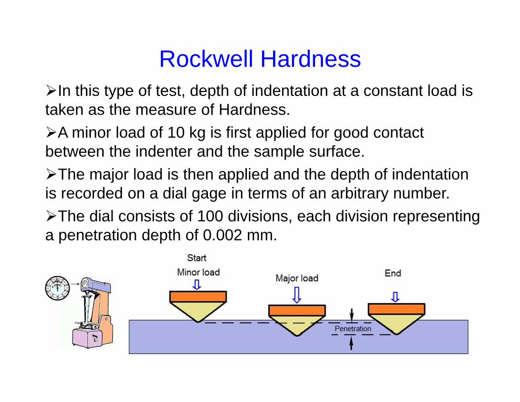
Rockwell HardnessIn this type of test, depth of indentation at a constant load is taken as the measure of Hardness. A minor load of 10 kg is first applied for good contact between the indenter and the sample surface.The major load is then applied and the depth of indentation is recorded on a dial gage in terms of an arbitrary number.The dial consists of 100 divisions, each division representing a penetration depth of 0.002 mm.
Rockwell Hardness
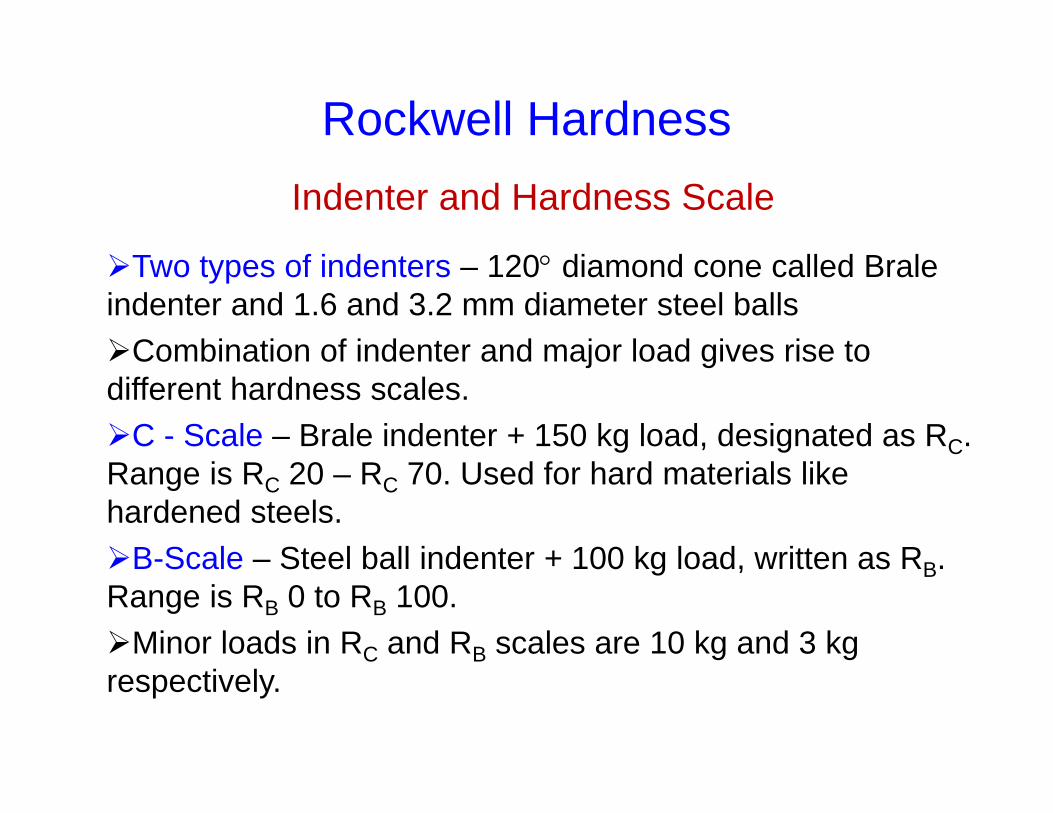
Two types of indenters – 120 diamond cone called Brale indenter and 1.6 and 3.2 mm diameter steel ballsCombination of indenter and major load gives rise to different hardness scales.C - Scale – Brale indenter + 150 kg load, designated as RC. Range is RC 20 – RC 70. Used for hard materials like hardened steels.B-Scale – Steel ball indenter + 100 kg load, written as RB. Range is RB 0 to RB 100.Minor loads in RC and RB scales are 10 kg and 3 kg respectively.
Indenter and Hardness Scale
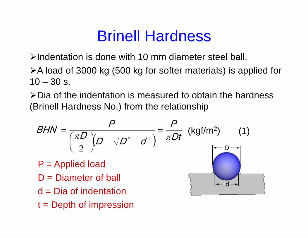
Brinell HardnessIndentation is done with 10 mm diameter steel ball.A load of 3000 kg (500 kg for softer materials) is applied for 10 – 30 s.Dia of the indentation is measured to obtain the hardness (Brinell Hardness No.) from the relationship
DtP
dDDDPBHN
22
2 D
d
P = Applied loadD = Diameter of ball d = Dia of indentationt = Depth of impression
(kgf/m2) (1)

Brinell Hardness
cos
1
22DPBHN
d = D sin
BHN varies with load. P/D2 value needs to be kept constant according to eqn. (2). P1/D1
2 = P2/D22 = P3/D3
2
(2)
D
d
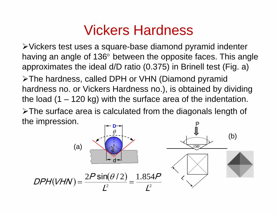
Vickers HardnessVickers test uses a square-base diamond pyramid indenter having an angle of 136 between the opposite faces. This angle approximates the ideal d/D ratio (0.375) in Brinell test (Fig. a)The hardness, called DPH or VHN (Diamond pyramid hardness no. or Vickers Hardness no.), is obtained by dividing the load (1 – 120 kg) with the surface area of the indentation.The surface area is calculated from the diagonals length of the impression.
22
854122LP
LPVHNDPH ./sin
(a)(b)
D
d

Microhardness
Sometime hardness determination is needed over a very small area.For example, hardness of carburised steel surface, coatings or individual phases or constituents of a material.The load applied is much smaller compared to macrohardness.The indentation is very small. An optical microscope is used to observe it. Sample preparation is needed.Two methods are used for microhardness testing.
Microhardness
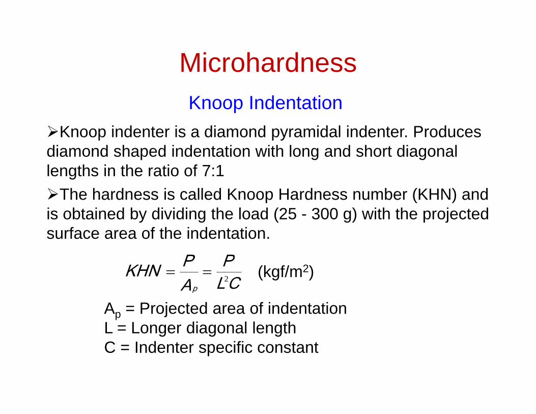
Knoop indenter is a diamond pyramidal indenter. Produces diamond shaped indentation with long and short diagonal lengths in the ratio of 7:1The hardness is called Knoop Hardness number (KHN) and is obtained by dividing the load (25 - 300 g) with the projected surface area of the indentation.
Knoop Indentation
CLP
APKHN
p2 (kgf/m2)
Ap = Projected area of indentationL = Longer diagonal lengthC = Indenter specific constant
Microhardness
This is same as Vickers hardness except that the applied load is much smaller so as to cover a small area.The applied load range is 1 – 100 g.
Vickers Microhardness
Tensile Properties
Stress and Strain
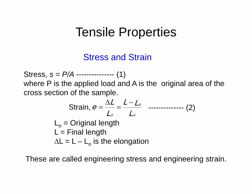
Stress, s = P/A --------------- (1) where P is the applied load and A is the original area of the cross section of the sample.
LLL
LLe
o
o
o
Strain,
Lo = Original lengthL = Final lengthL = L – Lo is the elongation
These are called engineering stress and engineering strain.
-------------- (2)

Elastic and Plastic behavior
All materials deform when subjected to an external load.Up to a certain load the material will recover its original dimensions when the load is released. This is known as elastic behavior.The load up to which the materials remains elastic is the elastic limit. The deformation or strain produced within the elastic limit is proportional to the load or stress. This is known as Hook’s Law , Stress Strain or Stress = E*Strain. E is known as the Elastic Modulus.When the load exceeds the elastic limit, the deformation produced is permanent. This is called plastic deformation. Hook’s law is no longer valid in the plastic region.
Tensile TestingLoad is applied uniaxially in a tensile testing frame and the displacement is recorded.The stress and strain are derived using equations (1) and (2) The stress is plotted against strain to generate the stress-strain curve. Different properties are calculated from this curve.
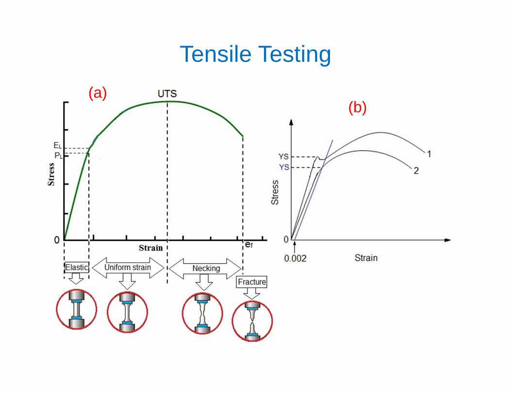
Tensile Testing(a)
(b)

Tensile PropertiesEL = Elastic limit, up to which Hook’s Law (Stress Strain) is valid. The material comes back to original shape when the load is released.Elastic limit is difficult to determine. The proportional limit, PL, the load at which the curve deviates from linearity, is taken as the elastic portion.The slope of the linear region is the Young’s Modulus or Elastic Modulus (E).Loading beyond PL produces permanent or plastic deformation. The onset point of plastic deformation is known as Yield stress (YS).In some materials like mild steel the yield point is prominent (Curve 1 in Fig. b)

Tensile PropertiesIn many other metals and alloys the yield point is not distinct (Curve 2, Fig. b). In such cases, a line parallel to the linear region is drawn at a strain = 0.002 (0.2%) and its intercept on the plastic region is taken as the yield stress (Fig. b). This is called 0.2% Proof stress. The stress at the maximum load is called ultimate tensile strength (UTS).The strain up to UTS is the uniform plastic strain. Beyond this the cross sectional area reduces and necking takes place.The fracture strain ef = (Lf - Lo)/Lo, where Lf is the length after fracture, is taken as the measure of Ductility.

Tensile PropertiesResilience:The ability of a material to absorb energy in the elastic region. This is given by the strain energy per unit volume Uo = ½ soeo (= so
2/2E) which is the area of the elastic regionToughness:Ability to absorb energy in the plastic range. This is given by the total area under the stress-strain curve.
High resilience is a property required in spring steels whereas structural steels have high toughness but lower resilience.

Ductile Vs. Brittle Fracture
The fracture strain ef = (Lf - Lo)/Lo, or reduction of area at fracture, q = (A – Ao)/Ao, is taken as the measure of Ductility.A ductile material exhibits high fracture strain, that is, it undergoes significant plastic deformation before fracture. A brittle material is the one which exhibits little or no plastic deformation before fracture.
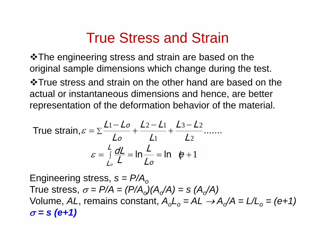
True Stress and StrainThe engineering stress and strain are based on the original sample dimensions which change during the test. True stress and strain on the other hand are based on the actual or instantaneous dimensions and hence, are better representation of the deformation behavior of the material.
.......2
23
1
121
LLL
LLL
LLLoo
True strain,
︶ln ︵ln 1 eLL
LdL
o
L
Lo
Engineering stress, s = P/AoTrue stress, = P/A = (P/Ao)(Ao/A) = s (Ao/A) Volume, AL, remains constant, AoLo = AL Ao/A = L/Lo = (e+1) = s (e+1)

True Stress-Strain Curve Since the engineering stress-strain curve is based on original area, it descends after maximum load as the load bearing ability of the sample decreases due to reduction in area.The true stress-strain curve (blue) however, continues to go up till fracture as it is based on the actual area.
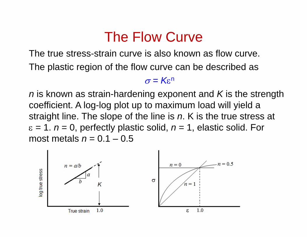
The Flow CurveThe true stress-strain curve is also known as flow curve.The plastic region of the flow curve can be described as
= Kn
n is known as strain-hardening exponent and K is the strength coefficient. A log-log plot up to maximum load will yield a straight line. The slope of the line is n. K is the true stress at = 1. n = 0, perfectly plastic solid, n = 1, elastic solid. For most metals n = 0.1 – 0.5
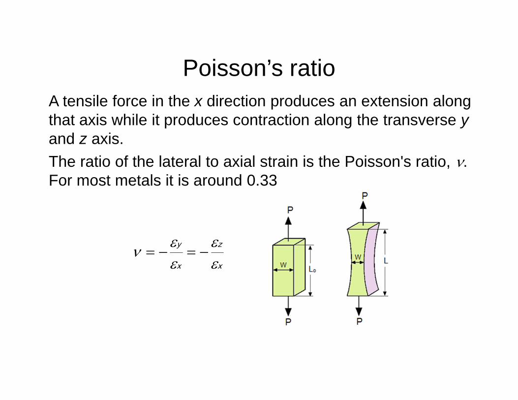
Poisson’s ratioA tensile force in the x direction produces an extension along that axis while it produces contraction along the transverse yand z axis. The ratio of the lateral to axial strain is the Poisson's ratio, . For most metals it is around 0.33
x
z
x
y

Shear Stress and Strain
The deformation in a body may also result in change in the initial angle between any two lines.The angular change is known as the shear strain, , which is produced by a shear stress, .
tanha
a
h
= G G is the shear modulus
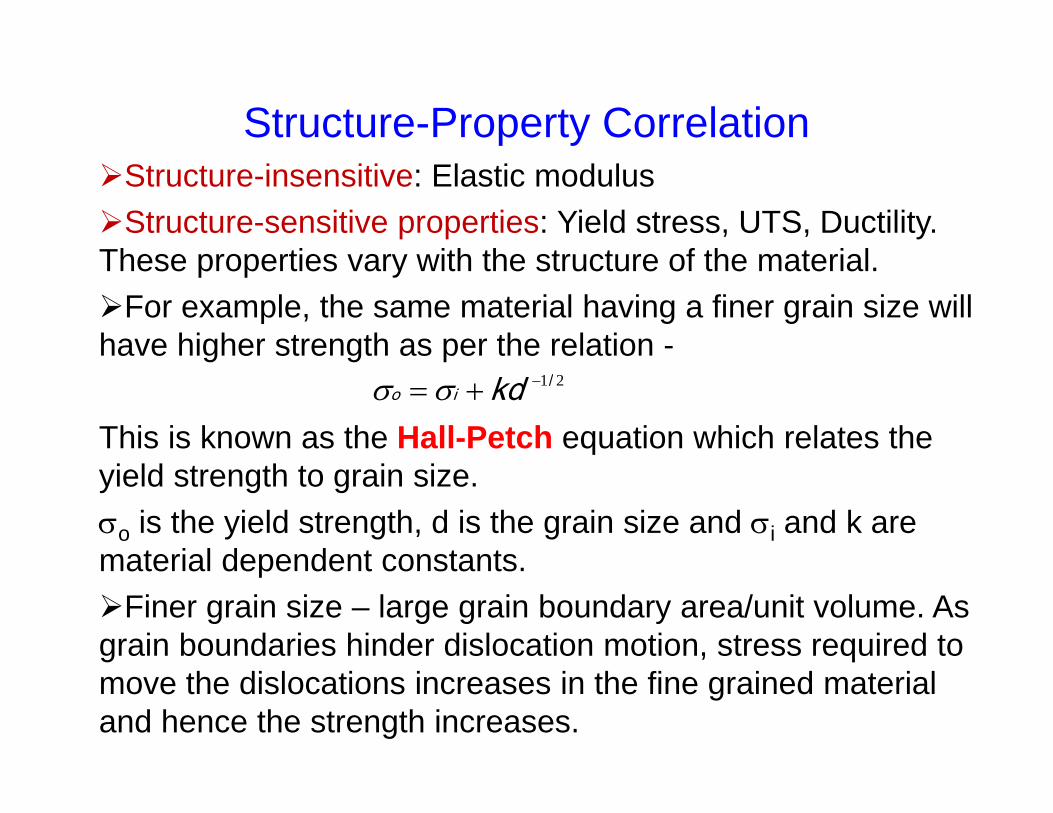
Structure-Property CorrelationStructure-insensitive: Elastic modulusStructure-sensitive properties: Yield stress, UTS, Ductility. These properties vary with the structure of the material. For example, the same material having a finer grain size will have higher strength as per the relation -
This is known as the Hall-Petch equation which relates the yield strength to grain size.o is the yield strength, d is the grain size and i and k are material dependent constants.Finer grain size – large grain boundary area/unit volume. As grain boundaries hinder dislocation motion, stress required to move the dislocations increases in the fine grained material and hence the strength increases.
21/ kdio

Mechanical Properties of some commonly used materials
Material E, GPa YS, MPa UTS, MPa %Elong. Poisson's ratio
C steel 207 220 ‐ 250 400 ‐ 500 23 0.30
Stain less steel 193 515 850 10 0.30
Alloy steels 207 860 1280 12 0.30
Al 70 34 90 40 0.33
Al alloys 72 ‐ 85 250 ‐500 300 ‐ 550 10 ‐20 0.34
Ti 103 170 240 30 0.34
Ti alloy 114 1100 1170 10 0.34
Mg 45 25 ‐ 40 50 – 60 8 – 10 0.35
Mg alloys 45 220 290 15 0.35
Ni 204 148 460 47 0.31
Ni super alloy 207 517 930 ‐ 0.21
Al2O3 380 550 ‐ 0.16
PET 2.7 ‐ 4 60 70 30‐300 0.39
References
Key words: Mechanical properties; Hardness; True stress; True strain; Strain hardening exponent; Flow curve ; Poisson’s ratio; Hall-Petch relationship
Mechanical Metallurgy, George E Dieter. McGraw Hill, Londonhttp://www.virginia.edu/bohr/mse209/chapter6.htmhttp://web.utk.edu/~prack/mse201/Chapter%206%20Mechanical%20Properties.pdfhttp://nptel.iitm.ac.in/courses/IIT-MADRAS/Design_Steel_Structures_I/1_introduction/3_properties_of_steel.pdf

ExamplesEx.1. A 15 mm long and 13 mm diameter sample shows the following behavior in a tensile test. Load at 0.2% offset – 6800 kg, maximum load – 8400 kg, fracture occurs at 7300 kg, diameter and length after fracture – 8 mm and 65 mm respectively. Find the standard mechanical properties.
Solution: Ao = (13)2/4 = 132.7 mm2, Af = (8)2/4 = 50.3 mm2
UTS = Pmax/Ao = (8400 x 9.8)/132.7 = 620 N/mm2 = 620 MPa0.2% proof stress = (6800 x 9.8)/132.7 = 502 N/mm2 = 502 MpaBreaking stress = (7300 x 9.8)/132.7 = 539 Mpa%elongation = 100*(Lf – Lo)/Lo = 100 x (65 – 50)/50 = 30%% area reduction = 100*(Af – Ao)/Lo = 100(132.7 – 50.3)/132.7 = 62%
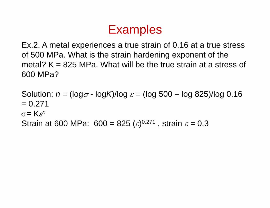
ExamplesEx.2. A metal experiences a true strain of 0.16 at a true stress of 500 MPa. What is the strain hardening exponent of the metal? K = 825 MPa. What will be the true strain at a stress of 600 MPa?
Solution: n = (log - logK)/log = (log 500 – log 825)/log 0.16 = 0.271= Kn
Strain at 600 MPa: 600 = 825 ()0.271 , strain = 0.3
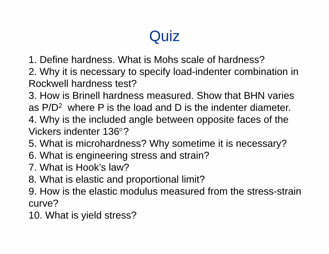
Quiz1. Define hardness. What is Mohs scale of hardness?2. Why it is necessary to specify load-indenter combination in Rockwell hardness test?3. How is Brinell hardness measured. Show that BHN varies as P/D2 where P is the load and D is the indenter diameter.4. Why is the included angle between opposite faces of the Vickers indenter 136?5. What is microhardness? Why sometime it is necessary?6. What is engineering stress and strain?7. What is Hook’s law?8. What is elastic and proportional limit?9. How is the elastic modulus measured from the stress-strain curve?10. What is yield stress?

Quiz11. What is 0.2% proof stress?12. How is the ductility measured?13. What is ductile and brittle behavior?14. What is resilience? What is toughness?15. What is true stress and strain. Deduce the relationship between true and engineering stress ad strain.16. Why does the engineering stress-strain curve peak and drop where as the true stress-strain curve keep on going up? 17. What is a flow curve?18. What is shear stress and strain19. What is Poisson's ratio?20. What are structure-sensitive and structure insensitive properties?21. What is Poisson's ratio?

Quiz22. A 15 mm long and 120 mm dia cylindrical rod is subjected to a tensile load of 35 kN. It must not experience either plastic deformation or a diameter reduction of more than 0.012 mm. Which of the listed materials is suitable for such a requirement and why? Al (E= 70 GPa, YS = 250 MPa, = 0.33), Ti (E= 105 GPa, YS = 850 MPa, = 0.36), Steel (E= 205 GPa, YS = 550 MPa, = 0.27), Mg (E= 45 GPa, YS = 170 MPa, = 0.35).
23. A metal experiences a true strain of 0.1 at a true stress of 415 MPa. What is the strain hardening exponent of the metal? K = 1035 MPa. What will be the true strain at a stress of 600 MPa?

Quiz24. The following data were obtained in a tensile test of a low-carbon steel of diameter 12 mm and gage length 50 mm.
Load, kN Elongation, mm Load, kN Elongation, mm2 0.0041 25.2 0.514 0.0082 28 1.526 0.0132 30 2.038 0.0183 34 3.05
10 0.0226 38.4 4.5712 0.0267 40 6.6014 0.0310 40.4 7.6216 0.0351 40.8 12.718 0.0391 40.2 14.720 0.0445 38.6 15.722 0.0485 36.4 17.824 0.0518 32.4 19.3
Plot Engineering and True stress-strain curve and find the tensile properties.