mechanical properties of aluminium bracket strengthening
TRANSCRIPT

MECHANICAL PROPERTIES OF ALUMINIUM
BRACKET STRENGTHENING
A. AMBROZIAK 1
The aim of the research is laboratory investigation of aluminium brackets employed to fasten lightweight curtain
walls to building facilities. Tensile loads perpendicular to end plates (vertical) were applied here. The author
focused on the solutions intended to increase the load-carrying capacity of aluminium brackets applying the plain
washer form A (DIN 125; ISO 7089), plain washer with an outer diameter about 3d (DIN 9021; ISO 7093) and
additional cover plates (straps) in the location of bolt anchoring on the base plate. The aluminium brackets were
tested on a steel base and concrete substrate. The flexibility of anchoring strongly affects the increase of the end
plate middle point displacement and movable crosshead displacement.
Keywords: aluminium bracket, cover plates, mechanical properties, EN AW-6060 T66
1. INTRODUCTION
Aluminium brackets form a group of the most popular elements applied to fasten lightweight
curtain walls to building facilities in civil engineering (e.g. in mullion-transom wall systems to
connect box-section aluminium profiles to structures, see Fig. 1). Curtain walls are complex
systems composed of separate components (see e.g. Kazmierczak [8]). One of the most important
design problems of curtain walls is a proper choice of a bracket and its fastening to a building
structure. Improper bracket design and/or its fastening may trigger problems with curtain walls (see
e.g. Tovarović et al. [9]). Moreover, inadequate support of glass façade elements eventually brings
about the extreme danger to life and property. Ambroziak et al. [1] have undertaken numerical and
analytical investigations of aluminium bracket strengthening by additional cover plates (straps) in
1 DSc., PhD., Eng., Prof. GUT, Gdansk University of Technology, Faculty of Civil and Environmental Engineering, St.
Gabriela Narutowicza 11/12, 80-233 Gdansk, Poland, e-mail: [email protected], ORCID: 0000-0002-7735-7863

the case of insufficient load-bearing capacity and stiffness due to design loads. The proposed
research addresses laboratory tests to experimentally assess the increase of bearing capacity of the
aluminium bracket applied to fasten lightweight curtain walls to building facilities.
Fig. 1. View on fixed aluminium brackets in mullion-transom wall system
Fig. 2. View and cross-section of analysed aluminium bracket
204 A. AMBROZIAK

2. MATERIALS
An investigated aluminium bracket consists of an end plate and two cantilever plates (Fig. 2). The
end plate is 180 mm wide and 140 mm high, showing various thickness: 8 mm and 5 mm (in the
middle of the end plate). The cantilever plate of 6 mm thickness is 145 mm wide and 140 mm high,
includes two normal holes of a 13 mm diameter. Two oval holes (13 mm by 30 mm, Fig. 2) in the
end plate are provided to fasten the aluminium bracket to the building structure.
Table 1. Mechanical properties of EN AW-6060 T66 according to EN 755-2 [5] properties values
Proof stress Re0.2 [MPa] 150Tensile strength Rm [MPa] 195
Elongation min. 8Elongation max. 8Brinell hardness 65
n-value in Ramberg-Osgood expression for plastic analysis 18
Table 2. Technical data of a single anchor in non-cracked normal concrete properties values
Nominal drill hole diameter d0 [mm] 12Min. member thickness hmin [mm] 120
Effective anchorage depth hef [mm] 70Installation torque Tinst [Nm] 60
Steel failure – characteristic resistance NRk,s [kN] 44.3Pullout failure – characteristic resistance in uncracked concrete C30/37
NRk,p [kN] 26.8
Displacement – factor for tensile load N� � [mm/kN] 0.06-0.14
In laboratory tests two variants of bases (steel plate and concrete foundation) were applied, see Fig.
3. In the first variant, two A4-70 stainless steel bolts M12 (diameter of 12 mm) were used to fasten
the aluminium bracket to the steel plate of 25 mm thickness. In the concrete foundation case two
bolt anchors made of A4 stainless steel were applied. The anchoring process of the aluminium
bracket on concrete consists of several actions. First of all the drill hole was made, next, the anchor
was hammered in, finally, the nut was tightened with a controlled torque equal 60Nm (Table 2).
Reinforced concrete elements were applied of strength class C30/37 (compressive strength: 30MPa
cylinder and 37 cube according to standard EN206 [7]), their dimensions are: thickness 20 cm,
width 38 cm and length 70 cm. The laboratory tests were focused on solutions to increase the load-
carrying capacity of aluminium brackets due to three types of washers applied in the location of bolt
anchoring on an end plate, see Fig. 2. The applications were tested of the A4 stainless steel flat
MECHANICAL PROPERTIES OF ALUMINIUM BRACKET STRENGTHENING 205

washer form A (DIN 125; ISO 7089), A4 stainless steel flat washer with an outer diameter about 3d
(DIN 9021; ISO 7093, called large washer) and additional aluminium cover plates (straps), see Fig.
4. The laboratory-tested concept of a strengthened end plate of the aluminium bracket by additional
cover plates (straps) can be compared with the concept of a reinforced T-stub flange with backing
plates (see e.g. Zoetemeijer [3], Nair et al. [4]). The aluminium bracket and cover plates (straps) are
made of EN AW-6060 T66 aluminium alloy. The material parameters for the EN AW-6060 T66
aluminium alloy can be found in civil engineering standards. Table 1 includes major mechanical
properties of the EN AW-6060 T66 aluminium alloy due to wall thickness from 3 to 25 mm. In the
case of concrete foundation, the M12 bolt anchors were installed in a drilled hole in a concrete
element and anchored by torque-controlled expansion. The base technical data due to torque-
controlled expansion anchor dedicated to concrete is available in Table 2.
Fig. 3. Analysed aluminium bracket with plain washers and cover plates (straps)
206 A. AMBROZIAK
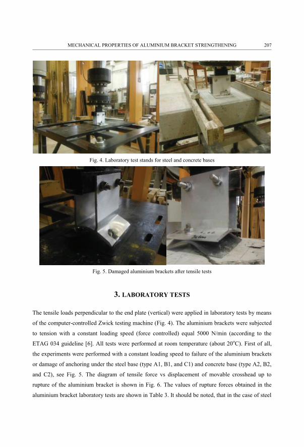
Fig. 4. Laboratory test stands for steel and concrete bases
Fig. 5. Damaged aluminium brackets after tensile tests
3. LABORATORY TESTS
The tensile loads perpendicular to the end plate (vertical) were applied in laboratory tests by means
of the computer-controlled Zwick testing machine (Fig. 4). The aluminium brackets were subjected
to tension with a constant loading speed (force controlled) equal 5000 N/min (according to the
ETAG 034 guideline [6]. All tests were performed at room temperature (about 20oC). First of all,
the experiments were performed with a constant loading speed to failure of the aluminium brackets
or damage of anchoring under the steel base (type A1, B1, and C1) and concrete base (type A2, B2,
and C2), see Fig. 5. The diagram of tensile force vs displacement of movable crosshead up to
rupture of the aluminium bracket is shown in Fig. 6. The values of rupture forces obtained in the
aluminium bracket laboratory tests are shown in Table 3. It should be noted, that in the case of steel
MECHANICAL PROPERTIES OF ALUMINIUM BRACKET STRENGTHENING 207

base the possibilities are damage of the end plate (see Fig. 5a) or failure of steel bolts. On the other
hand, in the case of concrete foundations, rupture forces are determined by the strength of bolt
anchoring (without cracks and tears of aluminium bracket), see Fig. 5b.
Fig. 6. Tensile force versus displacement up to rupture of aluminium bracket
Table 3. Rupture forces [kN] of aluminium bracket
steel base value concrete base valueA1_s1 70.3 A2_s1 53.4B1_s1 95.8 B2_s1 56.2C1_s1 81.4 C2_s1_s2mean 55.8
Fig. 7. Tensile force versus displacement – A type tests
Next, the force-controlled tests were carried out up to 60kN due to the steel base and up to 50kN
due to the concrete base. The force held every 5kN in its waiting time equal to 120s. When the force
reached the monitoring value (5kN, 10kN, etc.), displacement of the end plate (a point in Fig. 4)
208 A. AMBROZIAK

was measured. Displacement measurement of the middle point of the end plate was carried out at
the start of a specific load level. When the force reached 60kN in a steel base and 50kN in a
concrete foundation the aluminium brackets were unloaded after a specified waiting time. All C-
type specimens fulfilled the testing conditions, due to A and B types a single test leads to an end
only.
Figures 7-9 show the diagrams of tensile force vs displacement of movable crosshead due to A, B,
and C type tests. Displacements of movable crosshead (crosshead travel) under specific load are
collected in Tables 4 and 5 for steel base and concrete foundation, respectively. Additionally, the
displacement of the end plate middle point is shown in Tables 6 and 7 and in Figures 10-12.
Fig. 8. Tensile force versus displacement – B type tests
Fig. 9. Tensile force versus displacement – C type tests
MECHANICAL PROPERTIES OF ALUMINIUM BRACKET STRENGTHENING 209
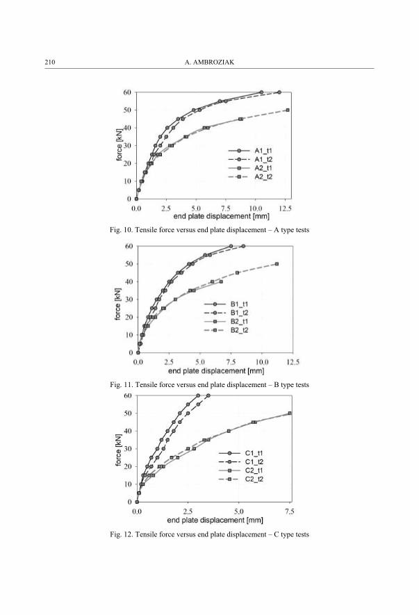
Fig. 10. Tensile force versus end plate displacement – A type tests
Fig. 11. Tensile force versus end plate displacement – B type tests
Fig. 12. Tensile force versus end plate displacement – C type tests
210 A. AMBROZIAK
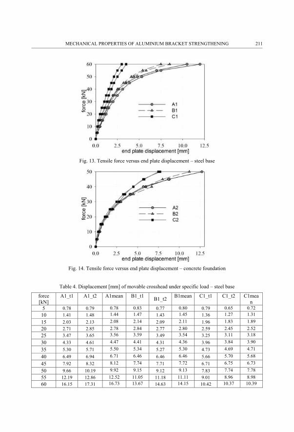
Fig. 13. Tensile force versus end plate displacement – steel base
Fig. 14. Tensile force versus end plate displacement – concrete foundation
Table 4. Displacement [mm] of movable crosshead under specific load – steel base
force [kN]
A1_t1 A1_t2 A1mean B1_t1 B1_t2 B1mean C1_t1 C1_t2 C1mean
5 0.78 0.79 0.78 0.83 0.77 0.80 0.79 0.65 0.7210 1.41 1.48 1.44 1.47 1.43 1.45 1.36 1.27 1.31
15 2.03 2.13 2.08 2.14 2.09 2.11 1.96 1.83 1.8920 2.71 2.85 2.78 2.84 2.77 2.80 2.59 2.45 2.5225 3.47 3.65 3.56 3.59 3.49 3.54 3.25 3.11 3.18
30 4.33 4.61 4.47 4.41 4.31 4.36 3.96 3.84 3.90
35 5.30 5.71 5.50 5.34 5.27 5.30 4.73 4.69 4.71
40 6.49 6.94 6.71 6.46 6.46 6.46 5.66 5.70 5.68
45 7.92 8.32 8.12 7.74 7.71 7.72 6.71 6.75 6.73
50 9.66 10.19 9.92 9.15 9.12 9.13 7.83 7.74 7.7855 12.19 12.86 12.52 11.05 11.18 11.11 9.01 8.96 8.9860 16.15 17.31 16.73 13.67 14.63 14.15 10.42 10.37 10.39
MECHANICAL PROPERTIES OF ALUMINIUM BRACKET STRENGTHENING 211

Table 5. Displacement [mm] of movable crosshead under specific load – concrete base
Force [kN]
A2_t1 A2_t2 A2mean B2_t1 B2_t2 B2mean
C2_t1 C2_t2 C2mean
5 0.71 0.64 0.67 0.59 0.58 0.58 0.89 0.74 0.81
10 1.43 1.26 1.34 1.29 1.12 1.20 1.69 1.41 1.55
15 2.02 1.98 2.00 2.09 1.92 2.00 2.45 2.07 2.26
20 2.71 2.89 2.80 2.97 2.89 2.93 3.35 3.08 3.21
25 3.65 4.15 3.90 3.93 3.96 3.94 4.31 4.28 4.29
30 4.91 5.44 5.17 5.22 5.21 5.21 5.39 5.51 5.45
35 6.47 7.06 6.76 6.93 6.73 6.83 6.65 6.84 6.74
40 8.32 9.16 8.74 9.38 8.73 9.05 8.14 8.34 8.24
45 11.46 12.13 11.79 21.0D3 11.20 - 9.80 10.16 9.98
50 19.1D1 20.8D2 - 14.63 - 11.85 12.46 12.15Rupture forces: D1=48.45kN; D2=50kN; D3=45.07kN
Table 6. Displacement [mm] of end plate middle point under specific load – steel base
force [kN]
A1_t1 A1_t2 A1mean B1_t1 B1_t2 B1mean C1_t1 C1_t2 C1mean
5 0.2 0.2 0.2 0.1 0.2 0.15 0.1 0.1 0.1
10 0.5 0.5 0.5 0.3 0.4 0.35 0.2 0.2 0.215 0.7 0.8 0.75 0.5 0.7 0.6 0.3 0.4 0.35
20 1.0 1.2 1.1 0.8 1.0 0.9 0.5 0.7 0.625 1.3 1.5 1.4 1.1 1.4 1.25 0.7 1.0 0.85
30 1.6 2.0 1.8 1.5 1.7 1.6 1.0 1.3 1.1535 2.0 2.5 2.25 2.0 2.2 2.1 1.2 1.5 1.35
40 2.6 3.1 2.85 2.5 2.7 2.6 1.5 1.8 1.6545 3.5 3.9 3.7 3.2 3.5 3.35 1.8 2.1 1.95
50 4.8 5.3 5.05 4.1 4.4 4.25 2.1 2.5 2.355 7.0 7.5 7.25 5.4 5.8 5.6 2.5 3.0 2.75
60 10.5 12.0 11.25 7.4 8.5 7.95 3.0 3.5 3.25
Table 7. Displacement [mm] of end plate middle point under specific load – concrete base
Force [kN]
A2_t1 A2_t2 A2mean B2_t1 B2_t2 B2mean
C2_t1 C2_t2 C2mean
5 0.2 0.2 0.2 0.1 0.1 0.1 0.1 0.1 0.1
10 0.5 0.4 0.45 0.4 0.3 0.35 0.3 0.3 0.3
15 0.8 0.7 0.75 0.8 0.6 0.7 0.8 0.6 0.7
20 1.3 1.2 1.25 1.4 1.2 1.3 1.3 1.1 1.2
25 1.8 2.0 1.9 2.1 2.0 2.05 2.0 1.7 1.85
30 2.8 3.0 2.9 3.0 3.0 3.0 2.8 2.5 2.65
35 4.1 4.2 4.15 4.5 4.2 4.35 3.5 3.3 3.45
40 5.7 6.0 5.85 6.7 6.0 6.35 4.5 4.5 4.5
45 8.8 8.7 8.75 -D3 8.0 - 5.8 5.7 5.75
50 -D1 12.7D2 - 11.2 - 7.5 7.7 7.6
212 A. AMBROZIAK

3. DISCUSSION AND CONCLUSIONS
The investigation is aimed at assessing mechanical properties of aluminium brackets
strengthened by washers and straps (cover plates) on steel base and concrete foundations. The paper
supplements and develops former investigations carried out by Ambroziak et al. [1], it may provide
scientists, engineers, and designers with an experimental and theoretical basis in the field of
mechanical properties of strengthened aluminium brackets. Based on the performed laboratory tests
the following conclusions may be drawn:
� Rupture forces of the aluminium bracket on a steel base (see Fig. 6 and Table 3) rise up
(36% and 15%) while applying the washer with an outer diameter about 3d (large washer)
and additional aluminium cover plates (straps). On the other hand, while an aluminium
bracket is tested on a concrete foundation (see Fig. 6 and Table 3) insignificant increase of
rupture forces (about 5%) is observed. Rupture forces are determined by means of bearing
capacity of bolt anchors. It should be noted that permissible loads for bolt anchoring are
affected by a great number of factors (see e.g. Ambroziak and Solarczyk [2]).
� The displacements of the end plate middle point of the aluminium bracket with cover plates
(C type) under tensile loads on a steel plate (see Fig. 13 and table 6) clearly exhibit the
increase in stiffness and decrease in displacements, comparing the A and B type specimens.
On the other hand, when aluminium brackets on concrete foundations were tested the
differences were apparent in the case of higher loads (see Fig. 14 and table 7). The
aluminium bracket with cover plates (C type) shows an increase in stiffness and decrease in
displacement over the tensile load of 25kN.
� The flexibility of anchoring strongly affects the increase of the end plate middle point
displacement and movable crosshead displacement (compare Figs. 7-12). It should be noted
that flexibility of anchoring on a steel base is restrained by stretching the steel bolts only
(see Fig. 5). When the torque-controlled expansion anchors are applied additional slip in the
anchoring is observed. The bolt anchor manufacturers' guidelines specify a displacement
value of bolt anchor under tensile load (see table 2, factor N� � mm/kN). The design of bolt
anchoring should be intended not only to fulfil loading conditions but also to compare their
flexibility (slip in anchoring due to loads).
� Laboratory tests on rigid metal profiles (steel plates) indicate different values of the middle
point displacement and movable crosshead displacement. The guidelines for determining the
MECHANICAL PROPERTIES OF ALUMINIUM BRACKET STRENGTHENING 213

resistance of aluminium brackets on rigid metal profile (see e.g. the ETAG 034 guideline
[6]) should be verified. The laboratory tests should be carried out on a concrete substrate
with specified anchoring systems to determine proper mechanical behaviour of aluminium
brackets.
The paper is dedicated to the engineers performing structural design of aluminium brackets to
fasten lightweight curtain walls to building facilities. It provides the information on mechanical
properties under vertical loads of aluminium brackets and the possibilities of its strengthening. The
results encourage the author to continue the research, on the basis of performing laboratory tests
with biaxial loads (vertical and horizontal), complemented by cyclic and rheological tests in order
to assess the long-time properties of aluminium brackets strengthened by additional aluminium
cover plates (straps) or stainless steel large washer.
REFERENCES
1. A. Ambroziak, M.T. Solarczyk, A. Biegus, “Numerical and analytical investigation of aluminium bracket strengthening.” Archives of Civil Engineering, 64(2): 37-54, 2018. DOI: 10.2478/ace-2018-0015
2. A. Ambroziak, M.T. Solarczyk, “Incorrect solutions in the field of anchoring in civil engineering.” Materiały Budowlane, 5: 18-19, 2017. DOI: 10.15199/33.2017.05.05
3. P. Zoetemeijer, “A design method for the tension side of statically loaded, bolted beam-to-column connections.” Heron 20(1) 1974, Delft University, Delft, Holland.
4. R.S. Nair, P.C. Birkemoe, W.H. Munse, “High Strength Bolts Subject to Tension and Prying.” Journal of the Structural Division, ASCE, 100(2): 351-372, 1974.
5. CEN (European Committee for Standardization) “Aluminium and aluminium alloys. Extruded rod/bar, tube and profiles. Mechanical properties.” EN 755-2, 2016 Brussels, Belgium.
6. EOTA (European Organisation for Technical Assessment) “Guideline for European Technical Approval of kits for external wall claddings part II: Cladding kits comprising cladding components, associated fixings, subframe and possible insulation layer.” ETAG 034, 2012, Brussels, Belgium.
7. CEN (European Committee for Standardization) “Concrete – Specification, performance, production and conformity.” EN 206+A1, 2013, Brussels, Belgium.
8. K. Kazmierczak, “Review of curtain walls, focusing on design problems and solutions.” Building Enclosure Science & Technology, Portland, April 12-14, BEST2 – Design and Rehabilitation – Session EE4-1, 1-20,2010. https://cdn.ymaws.com/www.nibs.org/resource/resmgr/BEST/BEST2_008_EE4-1.pdf
9. J. Č. Tovarović, N. Šekularac, J. Ivanović-Šekularac, “Problems Associated With Curtain Walls.” Structural Engineering International, 27(3), 413-417, 2017.
LIST OF FIGURES AND TABLES:
Fig. 1. View on fixed aluminium brackets in mullion-transom wall system
Rys. 1. Widok na zamocowanie konsoli aluminiowej w systemie słupowo-ryglowym
Fig. 2. View and cross-section of analysed aluminium bracket
Rys. 2. Widok i przekroje analizowanej konsoli aluminiowej
Fig. 3. Analysed aluminium bracket with plain washers and cover plates (straps)
Rys. 3. Analizowana konsola z testowanymi podkładkami i nakładkami (stemplami)
Fig. 4. Laboratory test stands for steel and concrete bases
214 A. AMBROZIAK

Rys. 4. Stanowisko badawcze na podłożu stalowym i betonowym
Fig. 5. Damaged aluminium brackets after tensile tests
Rys. 5. Zniszczone konsole aluminiowe po badaniach
Fig. 6. Tensile force versus displacement up to rupture of aluminium bracket
Rys. 6. Wykresy siła rozciągająca-przemieszczenie do zniszczenia konsoli aluminiowej
Fig. 7. Tensile force versus displacement – A type tests
Rys. 7. Wykresy siła rozciągająca-przemieszczenie – testy typ A
Fig. 8. Tensile force versus displacement – B type tests
Rys. 8. Wykresy siła rozciągająca-przemieszczenie – testy typ B
Fig. 9. Tensile force versus displacement – C type tests
Rys. 9. Wykresy siła rozciągająca-przemieszczenie – testy typ C
Fig. 10. Tensile force versus end plate displacement – A type tests
Rys. 10. Wykresy siła rozciągająca-przemieszczenie blachy podstawy– testy typ A
Fig. 11. Tensile force versus end plate displacement – B type tests
Rys. 11. Wykresy siła rozciągająca-przemieszczenie blachy podstawy– testy typ B
Fig. 12. Tensile force versus end plate displacement – C type tests
Rys. 12. Wykresy siła rozciągająca-przemieszczenie blachy podstawy– testy typ C
Fig. 13. Tensile force versus end plate displacement – steel base
Rys. 13. Wykresy siła rozciągająca-przemieszczenie blachy podstawy– podłoże stalowe
Fig. 14. Tensile force versus end plate displacement – concrete foundation
Rys. 14. Wykresy siła rozciągająca-przemieszczenie blachy podstawy– podłoże betonowe
Tab. 1. Mechanical properties of EN AW-6060 T66 according to EN 755-2 [5]
Tab. 1. Właściwości mechaniczne stopu EN AW-6060 T66 zgodnie z EN 755-2 [5]
Tab. 2. Technical data of a single anchor in non-cracked normal concrete
Tab. 2. Dane techniczne pojedynczego zakotwienia mechanicznego w niespękanym betonie
Tab. 3. Rupture forces [kN] of aluminium bracket
Tab. 3. Siły niszczące [kN] konsolę aluminiową
Tab. 4. Displacement [mm] of movable crosshead under specific load – steel base
Tab. 4. Przemieszczenia [mm] głowicy dla określonych obciążeń – podłoże stalowe
Tab. 5. Displacement [mm] of movable crosshead under specific load – concrete base
Tab. 5. Przemieszczenia [mm] głowicy dla określonych obciążeń – podłoże betonowe
Tab. 6. Displacement [mm] of end plate middle point under specific load – steel base
Tab. 6. Przemieszczenia [mm] blachy czołowej dla określonych obciążeń – podłoże stalowe
Tab. 7. Displacement [mm] of end plate middle point under specific load – concrete base
Tab. 7. Przemieszczenia [mm] blachy czołowej dla określonych obciążeń – podłoże betonowe
MECHANICAL PROPERTIES OF ALUMINIUM BRACKET STRENGTHENING 215

WŁAŚCIWOŚCI MECHANICZNE WZMOCNIONYCH KONSOL ALUMINIOWYCH
Keywords: konsole aluminiowe, właściwości mechaniczne, EN AW-6060 T66, wzmocnienie konsoli
STRESZCZENIE:
Przedmiotem przedstawionych w artykule badań są konsole aluminiowe, które są stosowane jako łączniki fasad
słupowo-ryglowych z konstrukcją budynku. Konsole wykonano ze stopu aluminium AW-6060 wg PN-EN 573-3:2004,
odmiana T66 wg PN-EN 515:1996. W pracy badano wpływ zastosowania w miejscu kotwieni konsol aluminiowych
zwykłej stalowej podkładki (typ A), powiększonej stalowej podkładki (typ B) oraz aluminiowych nakładek (tzw.
stempli, typ C). Konsole aluminiowe kotwiono do podłoża stalowego i betonowego wykorzystując śruby lub kotwy
mechaniczne. Zastosowanie dwóch typów podłoża, do którego kotwiono konsole aluminiowe, umożliwiło ocenę
wpływu podatności kotwienia mechanicznego na nośności i sztywności wzmacnianych konsol aluminiowych. Wyniki
badań wskazują iż zastosowanie aluminiowych nakładek, usytuowanych pod nakrętkami śrub łączących je z
konstrukcją budynku, zwiększa sztywności konsol aluminiowych. Nakładki wzmacniają lokalnie blachy czołowe
konsol. Ich zadaniem konstrukcyjnym jest m.in. zmniejszenie ramienia „zginania” c oraz zwiększenie sztywności
giętnej blachy czołowej konsoli.
Artykuł uzupełnia i rozwija badania prowadzone przez Ambroziaka i innych [1]. Wykonane i opisane badania stanowią
podstawę do szczegółowego opisania właściwości mechanicznych testowanych rozwiązań wzmacniania konsol
aluminiowych. Nośność konsoli aluminiowej zamocowanej do stalowej płyty wzrasta (od 15% do 36%) po
zastosowaniu podkładek powiększonych i dodatkowych nakładek aluminiowych. W przypadku kotwienia konsoli
aluminiowej do zbrojonego elementu betonowego obserwuje się nieznaczny wzrost nośności (około 5%). W tym
przypadku nośność konsoli aluminiowej determinowana jest nośnością zastosowanego kotwienia mechanicznego.
Przemieszczenia środkowego punktu blachy czołowej konsoli aluminiowej z nakładkami (typu C) zamocowanej do
podłoża stalowego pod obciążeniem rozciągającym wykazuje wzrost sztywności i zmniejszenie przemieszczeń w
porównaniu z typami A i B. Dla konsol aluminiowych kotwionych do podłoża betonowego efekt zwiększenia
sztywności z zastosowaniem nakładek widoczny jest w przypadku wyższych wartości obciążeń.
Podatność kotwienia silnie wpływa na zwiększenie przemieszczeń konsoli aluminiowej (w tym punktu środkowego
blachy czołowej) i utratę nośności konsoli. Podatność zamocowania konsoli do stalowej płyty ograniczona jest do
wydłużenia się stalowych śrub. W przypadku zastosowania kotew rozprężnych z kontrolowanych momentem
dokręcenia obserwuje się dodatkowy ich poślizg w zakotwieniu. Wytyczne techniczne producentów kotew określają
wartość tych przemieszczeń. Prawidłowy proces projektowania zakotwienia mechanicznego w przypadku konsol nie
powinien ograniczać się jedynie do spełnienia wymagań nośności łączników, ale także do ograniczenia ich podatności
(ograniczenia poślizgu w kotwieniu pod wpływem obciążeń). Do prawidłowej oceny nośności sztywności konsol
aluminiowych badania mechaniczne należy prowadzić na podłożu betonowym z zastosowaniem projektowanego
systemu kotwienia.
Received 31.07.2019
Revised 24.10.2019
216 A. AMBROZIAK