mechanical structure optimization of pipe inspection …article.scirea.org/pdf/46005.pdf · 58...
TRANSCRIPT
58
MECHANICAL STRUCTURE OPTIMIZATION OF
PIPE INSPECTION ROBOT FOR DOMESTIC WATER
PIPE LINE
Khairulnizam Othman1*
, M. Naim1, M. Iqbal
1, Naomi
1, N. Izlynda
1, Suhairi Ismail
1
1Department of Mechanical Engineering, Centre for Diploma Studies,
University Tun Hussein Onn Malaysia
86400, Parit Raja, Batu Pahat, Johor, Malaysia
Phone: +607453-8692; Fax: +607453-8660
*Email: [email protected]
ABSTRACT
Mechanical design pipe inspection robot with various pipe diameter adaptability and
automatic traction force installing is developed for long distance inspection of main water
pipe nondestructive evaluation and health monitoring with different diameter series. On the
basis of analyzing the mechanical actions of the adaptation to pipe diameter and traction force
installing, the related mechanical models are established, and their control system structure
and control strategy are discussed. The experimental results show that the theoretical analysis
in this research is valid and the prototype of this robot can work well in actual underground
water pipelines. As a mobile carrier for visual inspection and non-destructive testing to
monitor block, corrosion, crack, defect, and wall thickness of main water pipelines, its
inspection range extended around 1000 m wireless. Design and implementation consists in
SCIREA Journal of Mechanical Engineering
http://www.scirea.org/journal/Mechanical
October 20, 2016
Volume 1, Issue1, October 2016

59
combining the capacity of self-moving with that of self-sustaining and the property of low
weight and dimension.
Key words: Design pipe inspection; various pipe diameter; Traction force installing; Water
pipelines.
INTRODUCTION
Robotics is never end growing engineering field which improve human daily task and
increase work efficiency. These specific operations as inspection, maintenance, cleaning etc.
are expensive, thus the application of the robots appears to be one of the most attractive
solutions (Kim, Sharma, & Iyengar, 2010). The pipelines are the major tools for the
transportation of drinkable water, effluent water, fuel oils, sewage and gas. A lot of troubles
caused by piping networks aging, corrosion, cracks, and mechanical damages are possible.
Major concert on domestic water line is leak due to a damaged water pipe or pipe bursts. This
carry out responsibility for fixing it depends on which section of the pipe is damaged.
Allocation damage area takes a lot of time, need an effective seek out in finding the area of
breakdown. To understand why this might happen we need to first look at how the plumbing
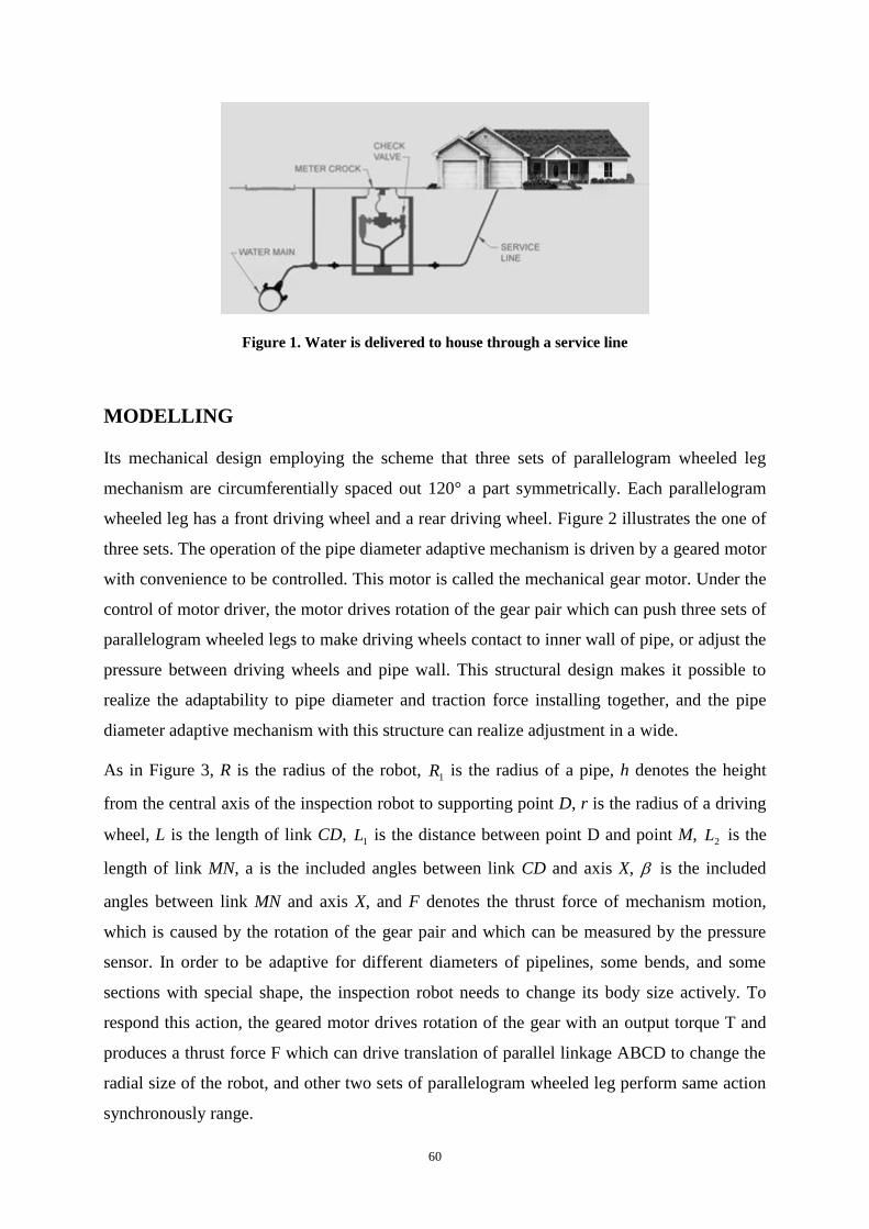
in your house connects to the water main in the street as in Figure 1.
Effectuate continuous activities for inspection, maintenance and repair are strongly demanded.
The robots with a flexible structure may boast adaptability to the environment, especially to
the pipe diameter, with enhanced dexterity, maneuverability, managing time and priorities,
capability to operate under hostile conditions (Li et al., 2007). The wheeled robots are the
simplest, most energy efficient, and have the best potential for long range. Loading the wheels
with springs, robots also offer some advantages in maneuverability with the ability to adapt to
in pipe unevenness, move vertically in pipes, and stay stable without slipping in pipes (Lee et
al., 2012; Kwon, Suh, & Yi, 2012). These types of robots also have the advantage of easier
miniaturization. The key problem in their design and implementation consists in combining
the capacity of self-moving with that of self-sustaining and the property of low weight and
dimension (Kim et al., 2009; Park, Kim, & Yang, 2009; Sadeghi & Moradi, 2008).
60
Figure 1. Water is delivered to house through a service line
MODELLING
Its mechanical design employing the scheme that three sets of parallelogram wheeled leg
mechanism are circumferentially spaced out 120° a part symmetrically. Each parallelogram
wheeled leg has a front driving wheel and a rear driving wheel. Figure 2 illustrates the one of
three sets. The operation of the pipe diameter adaptive mechanism is driven by a geared motor
with convenience to be controlled. This motor is called the mechanical gear motor. Under the
control of motor driver, the motor drives rotation of the gear pair which can push three sets of
parallelogram wheeled legs to make driving wheels contact to inner wall of pipe, or adjust the
pressure between driving wheels and pipe wall. This structural design makes it possible to
realize the adaptability to pipe diameter and traction force installing together, and the pipe
diameter adaptive mechanism with this structure can realize adjustment in a wide.
As in Figure 3, R is the radius of the robot, 1R is the radius of a pipe, h denotes the height
from the central axis of the inspection robot to supporting point D, r is the radius of a driving
wheel, L is the length of link CD, 1L is the distance between point D and point M,
2L is the
length of link MN, a is the included angles between link CD and axis X, is the included
angles between link MN and axis X, and F denotes the thrust force of mechanism motion,
which is caused by the rotation of the gear pair and which can be measured by the pressure
sensor. In order to be adaptive for different diameters of pipelines, some bends, and some
sections with special shape, the inspection robot needs to change its body size actively. To
respond this action, the geared motor drives rotation of the gear with an output torque T and
produces a thrust force F which can drive translation of parallel linkage ABCD to change the
radial size of the robot, and other two sets of parallelogram wheeled leg perform same action
synchronously range.

61
Figure 2. A various pipe diameter adaptive with wheeled leg mechanism.
Figure 3. Robot central axis forced distribution.
The structure of the robot central axis does not overlap the central axis of pipe as shown in
Figure 3, an additional torque is required to overcome the opposition caused by the transverse
friction between surface of pipe wall and the wheels supporting the gravity. This may result
over loading of the controlled motor. Therefore, we need to analyze this process, and establish
its mechanics model to guide the design.
Since the structure of the robot is symmetric, its center of gravity denoted by symbol G can be
assumed at its central axis. In Figure 3, symbol γ denotes the attitude angle of the robot which
can reflect its rotation round the central axis of a pipe, 1N and 2N respectively denote the

62
supporting force acting on the two sets of driving wheels by the gravity of the robot, θ is the
included angle between axis OZ and the line from the supporting point of a driving wheel to
the pipe center, s is the arc length of θ, z is the coordinate of G at axis OZ, and f denotes the
coefficient of transverse friction between driving wheels and pipe wall. From Figures 3 and 4,
we have geometric relationships
)sin(sin
sinsin
sinsin
coscos
sin
1
1
1
21
21
Rz
RR
Rs
LL
LLx
LhrR
(1)
where x is the coordinate of point N at axis X. Differentiating both sides of Eq. (1) yields
dRRR
Rdz
dRRR
Rds
dRhrRLLL
L
hrRLL
hrRLdx
222
1
2
222
1
1
22
1
2
2
2
1
22
1
sin
sincos
sin
sin
)()(
1)(
(2)
Ignoring frictional heating, considering a slope angle of pipe, and according to equilibrium
equation of forces and conservation of energy, we can obtain
coscos
sin
coscos
cos
coscos
222
1
121
mgdzNdsfFdx
RR
RmgmgNNN
(3)
Where N is the sum of all supporting force.
Defining

63
222
1
14
222
1
2
3
222
1
12
22
1
2
2
2
1
22
11
sin
sin
sincos
sin
sin
)()(
1)(
RR
Rk
RR
rk
RR
Rk
hrRLLL
L
hrRLL
hrRLk
N (4)
and substituting Eq. (2) into Eq. (3), we have
)(coscos
342
1
kfkkk
mgF
(5)
Then, the output torque of the geared motor can be written as
FP
T h
2 (6)
where denotes the transmission efficiency of the gear pair, hP denotes the lead of the gear.
When the motion motor of a wheeled robot can produce an enough driving force, its traction
force is determined by the adhesion force which depends on the normal pressure and adhesion
coefficient between driving wheels and pipe wall. Thus, a wheeled robot with the pipe
diameter adaptive mechanism, which can produce an additional normal pressure to change the
adhesion force between driving wheels and pipe wall, is capable of adjusting its traction force
in a certain range.
Along with the increase of inspection distance in pipeline upward, more traction force of the
robot is demanded to overcome increasing friction resistance of the gravity effect, or an
additional kinetic resistance caused by pipe slope (Kwon & Yi, 2012). However, when the
motion motor of the robot produces more driving force, the adhesion force only contributed
by robot weight may be insufficient, and its driving wheels may slip on the surface of pipe
wall. Therefore, an additional pressure enhancing adhesion force should be produced by the
pipe diameter adaptive mechanism to improve the traction capacity of the robot. This is
realized as the way that the action of the geared motor drives rotation of the gear pair with the
64
output torque T and produces the thrust force F which drives parallel linkage ABCD to press
the driving wheels against inner wall of the pipe with an additional pressure.
To realize the control of the adjustment of traction force, we should establish its mechanical
model on the basis of analyzing relationships among traction force, additional pressure, thrust
force, and output torque of the geared motor. We define the sum of all pressures applied to
driving wheels by the robot weight as total supporting force denoted by symbol N , and the
sum of pressures produced by pipe diameter adaptive mechanism actively as additional
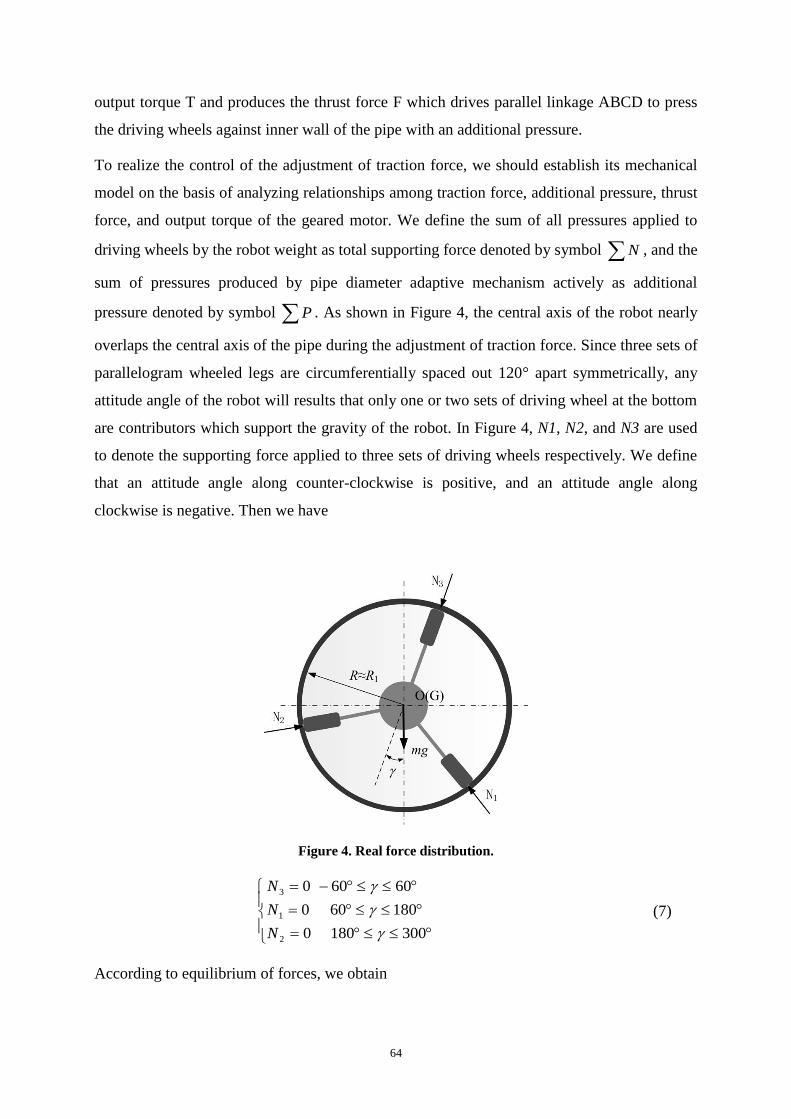
pressure denoted by symbol P . As shown in Figure 4, the central axis of the robot nearly
overlaps the central axis of the pipe during the adjustment of traction force. Since three sets of
parallelogram wheeled legs are circumferentially spaced out 120° apart symmetrically, any
attitude angle of the robot will results that only one or two sets of driving wheel at the bottom
are contributors which support the gravity of the robot. In Figure 4, N1, N2, and N3 are used
to denote the supporting force applied to three sets of driving wheels respectively. We define
that an attitude angle along counter-clockwise is positive, and an attitude angle along
clockwise is negative. Then we have
Figure 4. Real force distribution.
3001800
180600
60600
2
1
3
N
N
N
(7)
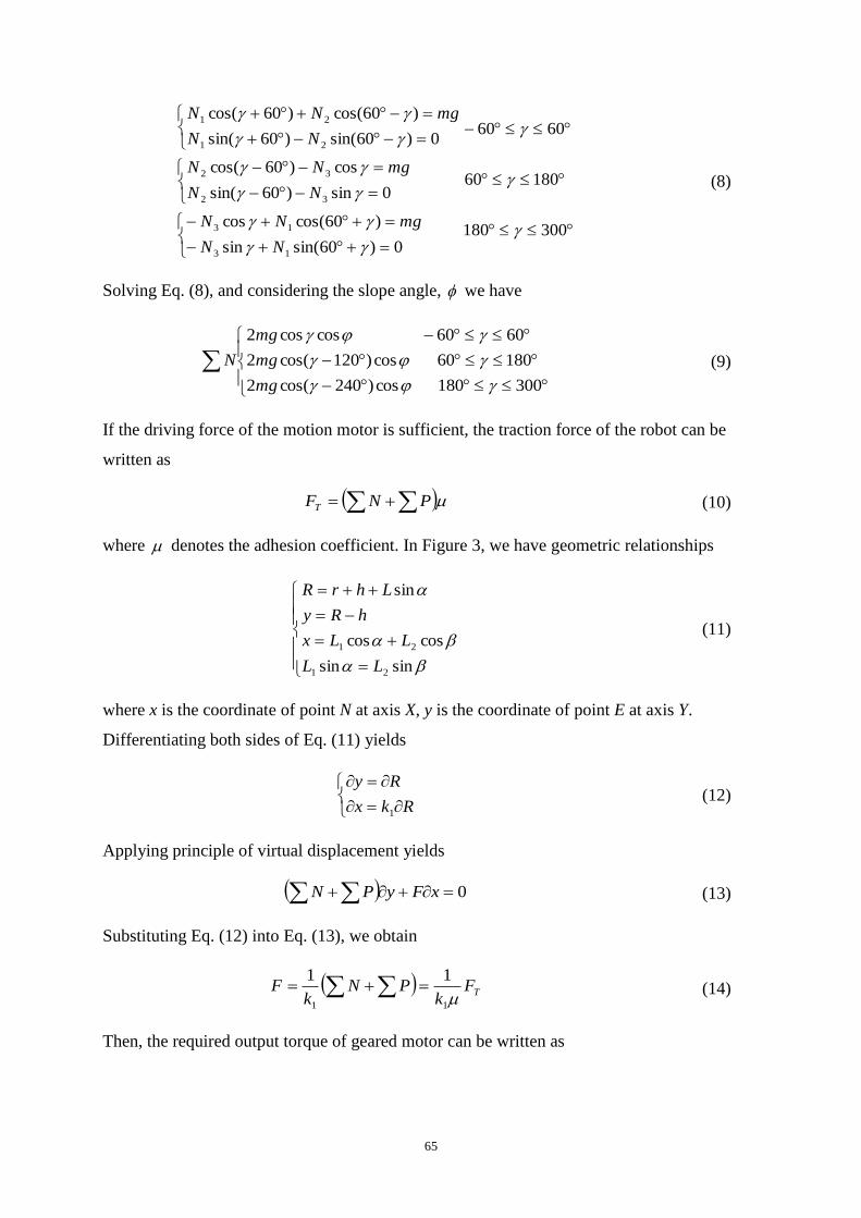
According to equilibrium of forces, we obtain
65
0)60sin(sin
)60cos(cos
0sin)60sin(
cos)60cos(
0)60sin()60sin(
)60cos()60cos(
13
13
32
32
21
21
NN
mgNN
NN
mgNN
NN
mgNN
300180
18060
6060
(8)
Solving Eq. (8), and considering the slope angle,
we have
300180cos)240cos(2
18060cos)120cos(2
6060coscos2
mg
mg
mg
N (9)
If the driving force of the motion motor is sufficient, the traction force of the robot can be
written as
PNFT (10)
where denotes the adhesion coefficient. In Figure 3, we have geometric relationships
sinsin
coscos
sin
21
21
LL
LLx
hRy
LhrR
(11)
where x is the coordinate of point N at axis X, y is the coordinate of point E at axis Y.
Differentiating both sides of Eq. (11) yields
Rkx
Ry
1
(12)
Applying principle of virtual displacement yields
0 xFyPN (13)
Substituting Eq. (12) into Eq. (13), we obtain
TFk
PNk
F11
11 (14)
Then, the required output torque of geared motor can be written as

66
Fp
T h
2 (15)
The mechanical model of the traction force employ is composed of Eqs. (9), (10), (14) and
(15) which can describe variations of the thrust force F, output torque T of the geared motor,
additional pressure RP, and traction force FT (Kim et al., 2009). When combining the virtual
force derived from a potential field which is generated at each wheel module, consider the
robot as a point of mass (Takahashi et al., 2011).
RESULTS AND DISCUSSION
From above mechanical model of dynamic adaptation to pipe diameter, it is known that both
the required thrust force F and the required output torque T change as 1R and R change in the
behaviour that the inspection robot adjusts its size to fit variation of pipe diameter, and both F
and T have different variation in the case of the pipe diameter being different as shown in
Figure 5, where D = 2R and11 2RD . The required F and T are more in pipelines with small
diameter than in pipelines with large diameter. In order to prevent the geared motor
overloading, we place a speed reducer with reduction rate of 10:1 between the geared motor
and gear, and verify the strength and rigidity of the related components bearing load.
(a) (b)

67
(c)
Figure 5. The 3D model of the pipe inspection robot (a), (b), components of robot (c)
The force that the robot mechanism exercises on the pipe walls is generated with the help of
an extensible spring. The helical spring disposed on the central axis assures the repositioning
of the structure, in the case of the pipe diameters’ variation. The components of the robot are,
(Figure 5, c): 1 - Helical spring, 2 - Translational rings, 3 - Actuator support, 4 - Motor, 5 -
Train gear, 6 – link, 7 - Central axis, 8 - Link joint, 9 -Wheel.
In the research, we proposed wheeled type in pipe robots characterized by an adaptable
structure based on linkages mechanisms. Compared with the previous research area robots,
our prototypes are characterized by a simple structure and kinematics, small number of
actuators, light weight, low power consumption. This robot has movement capacities for
inspection in 120 - 200 mm diameter pipes in horizontal or vertical configuration.
(a) (b)
Figure 6. Picture of the developed in pipe inspection robot
1
2
3
4
5
6
7
9
8

68
Elementary mechanism and the structural scheme of the robot is display in Figure 6. The
robot is powered through wires and it is controlled with the aid of a microcontroller
Microchip PIC18LF4620. The drive DC motors can be powered with the voltage between 2 –
3.5 V. The presented structure used a CCD camera for pipe inspection and sensor devices for
malfunction detecting system in pipe inspection (Jero & Ganesh, 2011).
CONCLUSION
In these research mechanical design pipe inspection robots are proposed. A very important
design goal of these robotic systems is the adaptability to the inner diameters of the pipes.
Thus, the studied pipe robots are characterized by an adaptable structure, based on linkage
mechanisms. The prototypes were designed in order to inspect pipes with variable diameters
within 120 and 200 mm which is suitable for water and gas pipeline in urban area. The
modular robotic system is development in low power consumption.
REFERENCES
[1] Jero, S. E. and Ganesh, A. B. 2011. PIC18LF4620 based customizable wireless sensor
node to detect hazardous gas pipeline leakage. Emerging Trends in Electrical and
Computer Technology IEEE Conference, 1: 563-566.
[2] Kim, D. W., Park, C. H., Kim, H. K. and Kim, S. B. 2009. Force adjustment of an active
pipe inspection robot. ICCAS-SICE IEEE Conference, 1: 3792-3797.
[3] Kim, J. H., Sharma, G. and Iyengar, S. S. 2010. Design concept and motion planning of a
single-moduled autonomous pipeline exploration robot. IECON 2010 -36th Annual
Conference on IEEE Industrial Electronics Society, 1: 1500-1505.
[4] Kwon, Y. S., Suh, J. T. and Yi, B. J. 2012. A linkage type mechanical clutch synthesis for
pipeline inspection robot. Automation Science and Engineering (CASE), 2012 IEEE
International Conference, 1: 618-623.
[5] Kwon, Y. S. and Yi, B. J. 2012. Design and Motion Planning of a Two-Module
Collaborative Indoor Pipeline Inspection Robot. Robotics, IEEE Transactions, 28(3):
681-696.
[6] Lee, D., Park, J., Hyun, D., Yook, G. and Yang, H. S. 2012. Novel mechanisms and
simple locomotion strategies for an in-pipe robot that can inspect various pipe types.
Mechanism and Machine Theory, 56: 52-68.
69
[7] Li, P., Ma, S., Li, B. and Wang, Y. 2007. Development of an adaptive mobile robot for
in-pipe inspection task. Mechatronics and Automation, 2007. ICMA 2007. International
Conference, 1: 3622-3627.
[8] Park, J., Kim, T. and Yang, H. 2009. Development of an actively adaptable in-pipe robot.
In Mechatronics, 2009. ICM 2009. IEEE International Conference, 1: 1-5.
[9] Sadeghi, M. and Moradi, A. 2008. Design and fabrication of a column-climber robot
(Koala robot). Industrial and Aerospace Engineering, 2: 220-225.
[10] Takahashi, M., Tada, Y., Suzuki, T. and Yoshida, K. 2011. Hierarchical Action Control
Technique Based on Prediction Time for Autonomous Omni-Directional Mobile Robots.
Journal of System Design and Dynamics, 5(4): 547-559.