mech/esse 2401 e g cad m c a d project
TRANSCRIPT

MECH/ESSE 2401 E NGINEERING G RAPHICS & CAD M ODELING – C OMPUTER
A IDED D ESIGN P ROJECT
Team Members: Ameer Rashid - 213766704 , Akash Oommen - 213725437 , Garen Keleshian - 213874359

Executive Summary
Presently, we have crafted a miniature hammer for a co-requisite course, MECH 2501 using the
University’s machine shop, which is situated in Bergeron. The hammer lacks flair and so, we had
been tasked to form design teams of exactly three students to develop detailed CAD models and
working drawings of a case with a locking mechanism for the hammer head using SolidWorks.
The term project was divided into five main tasks. Task 1 required us to create a solid model
(assembly) of the miniature hammer whose dimensions and geometries were to strictly follow
the engineering drawings provided by Prof. Alex Czekanski (Director of MECH 2501) by first
modeling the parts (handle, head, inserts) of the hammer using SolidWorks. In addition, we were
to create an engineering drawing of the hammer assembly using the standards learned in MECH
2401. Task 2 required each team member to prepare 10 free-hand sketches of the case (each
sketch was distinct but not necessarily practical). Thereafter, a team decision was made in order
to select four designs out of 30 possible designs taking into consideration several factors including
difficulty of modeling, fit, style, locking mechanism and hammer head dimensions and tolerances.
Then those four designs (Sketch # 10, 12, 18 and 24) were compared taking into consideration
the aforementioned criteria. Out of those four designs Sketch # 10 was chosen as a case for the
hammer head because of its relatively simple yet stylish design, easy to model locking mechanism
and close resemblance to the hammer head’s geometry. Task 3 required us to construct a solid
model (assembly) of the hammer head case using SolidWorks. In addition, we also had to create
an engineering drawing of the case assembly. To test if the case fits and its locking mechanism
works, we were to construct an assembly of the full hammer with the case applied in SolidWorks
using mates. Task 4 (optional) required us to use additive manufacturing techniques to 3-D print
the hammer head case by first preparing an .STL file(s) of the case and then using MakerBot to
print the case. Task 5 was to write a report on the chosen case design. This report will feature a
detailed table of contents, provide an in-depth discussion of the ideation process and rationale
for the design selection by comparing the selected case design to three other relatively good
designs, a thorough discussion of the final case design along with appropriate drawings and
complete step-by-step instructions of the modeling procedure using SolidWorks and a
justification for the case dimensions. The report will also feature a conclusion summarizing the
reasons Sketch # 10 was chosen amidst all others along with a restatement of the primary
objective(s) of the project and its learning outcomes. Lastly, the report will feature an appendix
which provides an in-depth overview of the role/contributions of each team member throughout
the term project, all ideation sketches completed in Task 2, all engineering drawings of individual
parts and assemblies, and any other additional information that would help improve the clarity
of this final report.

TABLE OF CONTENTS Introduction
Discussion of the Ideation Process and the Rationale for Design Selection
Discussion of the Final Design with Appropriate Drawings
Concluding Remarks
Appendices
• All engineering drawings of individual parts and assembly
• Any other additional information that would help to improve the clarity of the final
report.
• Role/contribution of each member in the term project

Introduction
This term project served two purposes, the first was to design a case for a miniature hammer
crafted in the co-requisite course MECH 2501 as it lacked flair. The second purpose was to
emphasize the importance of planning, the development of modeling strategies, the
consideration of tolerances and the spirit of teamwork. The chosen case had to meet several
criteria, three of them being that it had to tightly/closely fit the hammer head, have a functional
locking mechanism and be relative easy to model in SolidWorks. Before a final design was
selected each team member was required to prepare 10 free-hand sketches of the case (each
sketch being distinct but not necessarily practical). Thereafter, a team decision was made in order
to select four designs out of 30 possible designs taking into consideration the aforementioned
criteria and others such as style and hammer head dimensions and tolerances. These four designs
were compared and from them one was selected as the final case design. We chose Sketch # 10
because it met all the aforementioned criteria. To test if the final case design fit the hammer head
and its locking mechanism worked it was modeled and then assembled using SolidWorks and
applied to a full hammer assembly which consisted of the individual parts (handle, head and two
inserts). This report will feature a detailed table of contents, provide an in-depth discussion of
the ideation process and rationale for the design selection, a thorough discussion of the final case
design along with appropriate drawings and complete step-by-step instructions of the modeling
procedure using SolidWorks and a justification for the case dimensions and tolerance(s). The
report will also feature a conclusion summarizing the reasons Sketch # 10 was chosen amidst all
others along with a restatement of the primary objective(s) of the project and its learning
outcomes. Lastly, the report will feature an appendix which provides an in-depth overview of the
role/contributions of each team member throughout the term project, all ideation sketches
completed in Task 2, all engineering drawings of individual parts and assemblies, and any other
additional information that would help improve the clarity of this final report.

Discussion of the Ideation Process and the Rationale for Design
Selection
As stated before, the primary objective of the term project was to add flair to the miniature
hammer created in the co-requisite course MECH 2501 by designing a case for the hammer
head (not the entire hammer). Task 2 required each team member to prepare 10 free-hand
sketches of the case (each sketch being distinct but not necessarily practical). When sketching
each member knew that the case had to be one that tightly/closely fit the hammer head while
being durable and easy to model in SolidWorks. Thus, most team members used basic shapes
(rectangle, hexagon, and cylinder) as the base (portion in which the hammer head would rest)
in their sketches because initially, before adding the 15 revolved cuts to the hammer head,
it was a rectangle and even afterwards still retains those flat rectangular surfaces. Moreover,
these shapes would provide a matching fit for the hammer head thereby allowing a secure fit
and would be easiest to model in SolidWorks. As for the hammer head inserts, most sketches
accounted for those by adding circular or square extrusions on either side of the base because
the inserts themselves were circular, so using a square or cylindrical extrusion would provide
the closest and most secure fit for the inserts while being relatively easy to incorporate to the
solid model for the hammer head’s base. Many case sketches were such that they required two
halves for the case. This was to allow for ease of assembly without necessarily dissembling the
hammer (i.e. first removing the handle and then enclosing the hammer head in the case).
Furthermore, a lot of sketches used simple locking mechanisms e.g. a hinge and locks, velcro
straps (like those used to close an umbrella), push buttons, zippers and combinations of these.
After each member prepared his 10 free-hand sketches for the hammer head case, a team
decision was made in order to select four designs out of 30 possible designs taking into
consideration several factors including difficulty of modeling, fit, style, locking mechanism and
hammer head dimensions and tolerances. We chose Sketches # 10, 12, 18 and 24. Then each of
these sketches were compared (pros and cons) using the aforementioned criteria. Sketch # 10
(refer to appendices page 15) consisted of two identical pieces labeled piece 1 and piece 2
respectively. Both piece 1 and piece 2 consisted of a rectangular base with extruded half arcs in
which the hammer head plus inserts (i.e. the hammer head with the inserts screwed in) would
rest. Piece 1 had a hole for the handle while piece 2 did not. Both pieces had a wall of thickness
Z. However, on the top of the walls of piece 1, a groove pattern was made. This groove of depth
X was created as part of the locking mechanism for this design. On the top of the walls of piece
2, an extrusion of height Y was created because this extruded part would fit inside the grooves
in the walls of piece 1. Sketch # 10 utilized a tongue and joint locking mechanism. Sketch # 12
(refer to appendices page 16) consisted of a cylinder that was threaded towards the top so it
could be opened or closed with circular lid (similar to a medicine bottle). Sketch # 12 had a hole
that was cut in the bottom of the cylinder for the hammer handle. Sketch # 18 (refer to
appendices page 19) consisted of a rectangular box with a lid on top that would serve as the

locking mechanism. It also had a hole in the bottom for the handle. Sketch # 24 (refer to
appendices page 21) consisted of a double-arrow shaped base that was extruded some height
and turned on its side. It had a hole in one of its side faces to allow for the insertion of the
hammer handle. Sketch # 12 was not considered because of its locking mechanism (medicine
bottle style) which would prevent the case from sitting level with a flat surface. It would also
look strange from one end because the lock portion (i.e. the lid) would be larger than the closed
end. Sketch # 18 was not considered because its design was far too simple (shoe box). Also, its
locking mechanism was not very secure, if the hammer were held upside down the lid would fall
off. Sketch # 24 was not considered because it lacked a clear locking mechanism and the
triangular portion where the inserts would be situated would not provide a tight fit. Thus, out of
those four sketches, Sketch # 10 was chosen as a case for the hammer head because of its
relatively simple yet stylish design, easy to model locking mechanism and close resemblance to
the hammer head’s geometry.

Discussion of the Final Design with Appropriate Drawings
Sketch # 10 was chosen as a case for the hammer head because of its relatively simple yet stylish
design, easy to model locking mechanism and close resemblance to the hammer head’s
geometry. Using SolidWorks, the case was dimensioned such that the interior of the base
(rectangle) matched the maximum exterior dimension of the hammer head (45.2 mm X 20.2 mm).
This sketch was then extruded 2 mm in height to add thickness to the base. Then the base’s
exterior dimensions were chosen by drawing a rectangle around the interior base sketch which
was 2 mm greater in length and width in every direction than the length and width of its interior
sketch i.e 49.2 mm X 24.2 mm. The exterior base sketch was then extruded 2 mm in the
downward direction and 10.2 mm in the upward direction. The 2 mm extrusion in the downward
direction was to ensure that the exterior base sketch was at the same height as the interior base
sketch before being extruded a further 10.2 mm in the upward direction. As for the 10.2 mm
extrusion in the upward direction, it was to account for the maximum half way height dimension
of the actual hammer head. Moreover, by extruding the exterior base sketch, a wall of 2 mm
thickness was created around the interior base sketch of 45.2 mm X 20.2 mm. A thickness of 2
mm was chosen as it was necessary to create the locking mechanism for this design. Then a circle
of diameter 19.2 mm was drawn on one of the exterior (24.2 mm) faces of the rectangular base
and extruded 2 mm inwards and 10.2 mm outwards to create the portion of the case where the
insert would rest. Thereafter, a tangent arc of radius 11.1 mm was drawn on the bottom portion
of the circular extrusion by drawing a line of length 1.5 mm from each center-point edge of the
circular extrusion’s face and then connected by a 19.2 mm line drawn through the center of the
circular extrusions face. This arc was then extruded 2 mm outwards to account for the thickness
of the circular portion of the case where the insert would rest and 10.2 mm inwards (i.e. up to
the wall of the exterior base extrusion). Afterwards, a circle of diameter 19.2 mm was drawn
overlapping the previously extruded 19.2 mm circle. Then the extruded cut feature was used on
the overlapping circle (extruding inwards at 12.2) to remove the previously extruded 19.2 mm
circle. As a result, a half circle shape (tangent arc that was extruded 2 mm beyond the extrusion
point of the 19.2 mm diameter circle) was left. This half circle was created because the design for
this case involved two identical parts. Thus, when the two parts were joined a full circle which
would enclose the inserts was made. Now, the same procedure was applied to the other exterior
face of the base to make a portion to secure the second hammer insert. On the top face of the
walls a groove (refer to drawing 1) was made which was 2 mm deep and of varying thickness from
the center line of the walls. The thickness varied because the interior and exterior diameters of
the circular extrusions did not match with the interior and exterior lengths of the base walls upon
which they were constructed. Lastly, a circle of diameter 18.6 mm was drawn on the bottom
interior face of the rectangular base from the middle (22.6 mm) and cut using extruded cut. A
hole of 18.6 mm was created so that this portion of the case could simply slide through the
hammer handle (which has a maximum diameter of 18.5 ± 0.2 mm) without the need to
disassemble the entire hammer and then be sealed by the other identical half. Then a new part
file was made and the exact same procedures were used to construct the other identical half of
the first case piece. The only difference with the second case piece was that instead of extruded
cutting the groove pattern which was drawn on the top of the walls; it was extruded upwards by
2 mm from the face of the walls (refer to drawing 2). This was to complete the locking mechanism
for the case. The 2 mm extrusion would fit into the groove created on the previous piece thereby
locking the case. The hammer head measures 45 ± 0.2 mm along its length and 20 ± 0.1 mm
along its width and height. The half way height of the head measures 10 ± 0.2 mm. The inserts
measure 10 ± 0.2 mm (the threaded 10 mm portion is ignored here because it will fit inside the
hammer head). The major diameter of the inserts is 19 mm (ignoring the 8 mm diameter of the
threaded portion). The dimensions for the interior base and interior portion for the inserts were
all 0.2 mm greater than their actual part dimensions. This was to ensure a fairly tight/close fit,
had the interior dimensions been the same as the hammer head and insert assembly it may not
have fit/resulted in interference. The base thickness was chosen to be 2 mm to ensure the case
would be durable when printed. A tolerance of − 0.1 mm was selected for all
features/dimensions of the case as this would still allow all case feature dimensions to be greater
than the hammer head dimensions, which means the hammer head would still fit, only a little
tighter.

Hammer Head Case Engineering Drawing # 1:

Hammer Head Case Engineering Drawing # 2:

Conclusion
The primary objective of this term project was to create a case for the miniature hammer
created in the co-requisite course MECH 2501 to add some flair. The case had to tightly/closely
fit the hammer head while being durable. The ideation process required each team member to
prepare 10 free-hand sketches of the case (each sketch was distinct but not necessarily
practical). Thereafter, a team decision was made in order to select four designs out of 30
possible designs taking into consideration several factors including difficulty of modeling, fit,
style, locking mechanism and hammer head dimensions and tolerances. We chose sketches #.
These sketches were compared (pros and cons) using the aforementioned criteria. Of those
four sketches Sketch # 10 was chosen as a case for the hammer head because of its relatively
simple yet stylish design, easy to model locking mechanism and close resemblance to the
hammer head’s geometry. The case had a rectangular base to fit the hammer head because
initially, the hammer head was a rectangle before the 15° revolved cuts and even after the cuts
it still had mostly flat rectangular faces. As a result the case would tightly fit the hammer head.
Another reason this shape was chosen for the base was because of its ease to model in
SolidWorks. The insert portion of the case was simply a combination of circular and tangent arc
extrusions and cuts on each side face of the rectangular base because they would be easy to
model onto the faces and fit the exact shape of hammer head inserts. The full case consisted of
two pieces, one with a 2 mm groove atop the face of its walls (created by extruding a 2 mm
thick rectangle around the interior base) and an 18.6 mm diameter extruded cut hole trough
the bottom interior rectangular face and the other with a 2 mm extrusion atop the face of its
walls. This was to allow ease of case assembly without the need to remove the handle from the
head first. The tongue and groove joint was selected as the locking mechanism because of its
ease of modeling and assembly in SolidWorks as well as practical, real-life examples of its use.
Most case features were dimensioned such that their dimensions were 0.2 mm greater than the
dimensions of the hammer head plus insert assembly. This was to provide a secure fit for the
hammer head while remaining relatively close to the “perfect/exact” measurements for the
head and to ensure that the case would work in situations where the hammer head’s
dimensions were off. A tolerance of − 0.1 mm was selected for all features of the case as this
would still allow all case feature dimensions to be greater than the hammer head dimensions,
which means the hammer head would still fit, only a little tighter.

Appendices
All engineering drawings of individual parts and assembly


Any other additional information that would help to improve the clarity of the
final report:
Hammer Case Render:
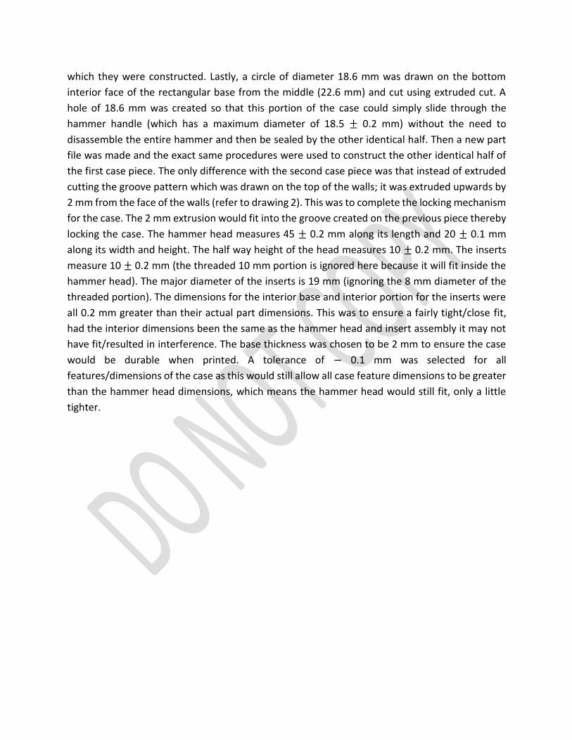
Full Hammer plus Case Assembly:
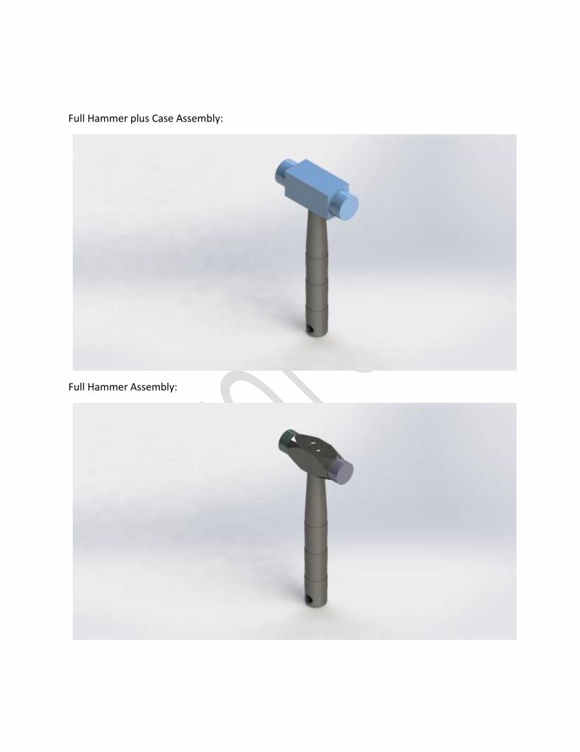
Full Hammer Assembly:

Role/contribution of each member in the term project:
Akash Oommen:
• Wrote the executive summary and the introduction
• Completed his individual 10 free-hand sketches
• Modeled the hammer head and handle
• Designed the case
• Made the full hammer assembly and the full hammer plus case assembly
• Completed the engineering drawings for the hammer components (head, handle and
inserts)
Ameer Rashid:
• Made the title page
• Completed his individual 10 free-hand sketches
• Modeled the hammer handle and both parts of the case
• Wrote the ideation processes/rationale for design selection and the first half of the
discussion for final design
• Edited/formatted the report
• Selected the colors/materials for the hammer components (head, handle and inserts)
• Prepared the final renders for the full hammer assembly, full hammer assembly plus
case and the case assembly
Garen Keleshian:
• Wrote the 2nd half of the discussion for final design and the conclusion
• Completed his individual 10 free-hand sketches
• Modeled the inserts
• Completed the engineering drawing for the hammer case