media rewind upgrade - zebra technologiesmedia rewind upgrade preparing the printer 6 33181l-001...
TRANSCRIPT

© 2006 ZIH Corp. All product names and numbers are Zebra trademarks, and Zebra and the Zebra logo are registered
trademarks of ZIH Corp. All rights reserved.
33181L-001 Rev. A10/23/2006
Printed on chlorine-free recycled paper.
Media Rewind Upgrade
Installation Instructions
Prepare for InstallationThis kit includes the parts and documentation necessary to install the media rewind option kit into the 105SL™ printers. Read these instructions thoroughly before attempting to install this kit.
Parts List
Caution • A qualified service technician must perform this installation.
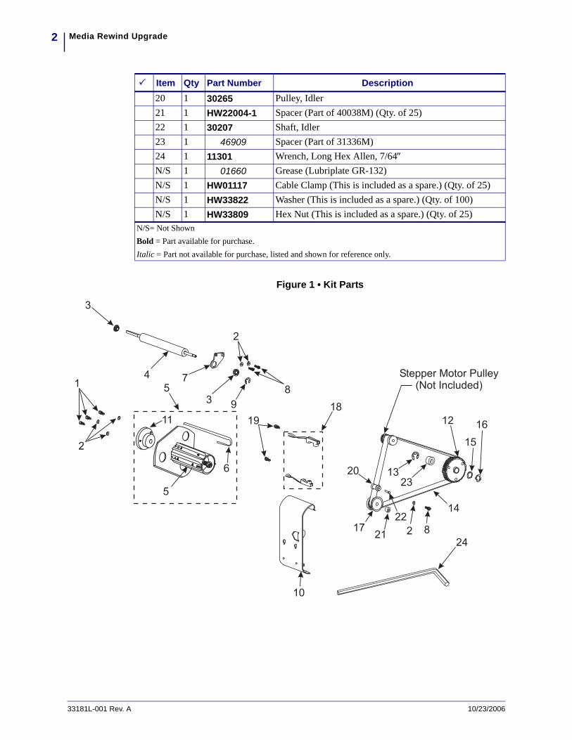
Item Qty Part Number DescriptionRef 1 G33181 Kit, Rewind Upgrade 105SL1 3 HW30393-006 Screw, 8-32 x 0.37, Socket Head Cap (Qty. of 25)2 6 HW40193 Washer, Flat 0.406 x 0.172 x 0.048 (Qty. of 25)3 2 49688 Bearing, Flanged (Part of 40038M)4 1 32416 Platen Roller5 1 32122 Media Take-Up Spindle6 1 47062-2 Hook, Rewind (Part of 32122)7 1 32347 Bracket, Platen Support 8 3 HW30392-004 Screw, 6-32 x 0.25, Socket Head Cap (Qty. of 50)9 3 HW33810 C-Ring (Two are included as a spares.) (Qty. of 100)10 1 G48383M Assembly, Std. Rewind Plate11 1 30334-7 Assembly, Bearing Housing (Part of 32122)12 1 31336M RTU/MTU Pulley Assembly13 1 HW33811 E-Ring (Qty. of 25)14 1 45189-2 Belt, Rewind Drive 15 1 HW33804 Washer, Flat 0.76 x 0.51 x 0.03 (Qty. of 25)16 1 HW30115 Washer, Wave (Qty. of 25)17 48018 Pulley, Rewind18 1 G46609-4M Assembly, Lower Take Label Sensor. (Black/Red Wires)
Assembly Upper Take Label Sensor. (Green/Yellow Wires)
19 2 HW32334 Screw, 6-32 x 0.37(Included as spares.) (Qty. of 100)N/S= Not ShownBold = Part available for purchase.Italic = Part not available for purchase, listed and shown for reference only.
Media Rewind Upgrade2
33181L-001 Rev. A 10/23/2006
Figure 1 • Kit Parts
20 1 30265 Pulley, Idler21 1 HW22004-1 Spacer (Part of 40038M) (Qty. of 25)22 1 30207 Shaft, Idler23 1 46909 Spacer (Part of 31336M)24 1 11301 Wrench, Long Hex Allen, 7/64″N/S 1 01660 Grease (Lubriplate GR-132)N/S 1 HW01117 Cable Clamp (This is included as a spare.) (Qty. of 25)N/S 1 HW33822 Washer (This is included as a spare.) (Qty. of 100)N/S 1 HW33809 Hex Nut (This is included as a spare.) (Qty. of 25)
Item Qty Part Number Description
N/S= Not ShownBold = Part available for purchase.Italic = Part not available for purchase, listed and shown for reference only.
19
82
1
2
3
10
5
6
5
11
7
2
83
4 Stepper Motor Pulley(Not Included)
17
12
13
14
15
16
21
18
22
2320
9
24

3Media Rewind Upgrade
10/23/2006 33181L-001 Rev. A
Reference Materials
Tools Required
Differences in Printer Configurations
The printer identification label on the rear of the unit identifies the configuration of the printer. The format of the Configuration Number is as follows:
10500-1XXX-XXXX
These instructions cover the two major configurations of the 105SL. The significant differences between configurations are denoted by the first digit of the second group of numbers. If that digit is a zero (0) or one (1), the 105SL has separate AC and DC power supplies. If that digit is a two (2) or three (3), the 105SL has an integrated AC/DC power supply. The main logic board is different in the two configurations.
105SL User CD
105SL User Guide
105SL Quick Reference Guide
105SL Maintenance Manual
Tools • You need these tools to complete this procedure:
Phillips Screwdriver Set
Hex Head Driver 7/64 in. Extended Reach (10 in. shaft)
Standard Hex Key (Allen Wrench) Set
Standard Nutdriver Set
11303 Spring Gauge 2200g
Antistatic Wriststrap and Mat
Needle Nose PliersLong Needle Nose Pliers
Metric/inch Ruler
Safety Goggles

Media Rewind UpgradePreparing the Printer
4
33181L-001 Rev. A 10/23/2006
Preparing the Printer
Printer Configurations 10500-0XXX-XXXX and 10500-1XXX-XXXX.
The printer must be partially disassembled to install the various parts provided in this kit. Use the following procedure to disassemble the printer.
1.
2.
3.
4. Remove the two screws securing the electronics cover. Remove the cover.
Note • Retain all parts removed during disassembly, unless otherwise directed.
Caution • Observe proper electrostatic safety precautions when handling static-sensitive components such as circuit boards and printheads.
Connect yourself to an antistatic device.
Caution • Turn off (O) the printer and disconnect it from the power source before performing the following procedure.
Turn off (O) the printer and disconnect the AC power cord and all data cables.
Caution • While performing any tasks near an open printhead, remove all rings, watches, hanging necklaces, identification badges, or other metallic objects that could touch the printhead.
Open the right side media cover and remove all media and ribbon from the printer.
Note • You can leave all wires and cables attached to the DC power supply board. With wires still attached, move the assembly aside to gain access to the area of the printer you need to install the kit parts.

5Media Rewind UpgradePreparing the Printer
10/23/2006 33181L-001 Rev. A
5. See Figure 2. Inside the electronics cabinet, remove the two nuts and one mounting screw that secure the DC power supply assembly in position.
Figure 2 • DC Power Supply Removal/Installation
6. Remove the DC power supply assembly from the printer chassis.
Note • The black heat conduction pad MUST NOT be discarded.
POWER
TAKE LABEL
ERROR
CHECK RIBBON
CANCEL
FEED
PAPER OUT
PAUSE
DATA
PREVIOUSPREVIOUS
NEXT/SAVENEXT/SAVE
SETUP/EXIT
SETUP/EXIT
DC Power Supply AssemblyHex Nut
Screw
Do Not RemoveHeat Conduction Pad

Media Rewind UpgradePreparing the Printer
6
33181L-001 Rev. A 10/23/2006
Printer Configurations 10500-2XXX-XXXX and 10500-3XXX-XXXX.
The printer must be partially disassembled to install the various parts provided in this kit. Use the following procedure to disassemble the printer.
1.
2.
3.
4. Remove the two screws securing the electronics cover. Remove the cover.
5. See Figure 3. Remove and retain the two screws securing the insulation shield to the standoffs on the power supply. Carefully unwrap the top of the shield and remove it from the power supply.
Caution • Observe proper electrostatic safety precautions when handling static-sensitive components such as circuit boards and printheads.
Connect yourself to an antistatic device.
Caution • Turn off (O) the printer and disconnect it from the power source before performing the following procedure.
Turn off (O) the printer and disconnect the AC power cord and all data cables.
Caution • While performing any tasks near an open printhead, remove all rings, watches, hanging necklaces, identification badges, or other metallic objects that could touch the printhead.
Open the right side media cover and remove all media and ribbon from the printer.
Important • Certain components located under the insulation shield can store a residual charge for as long as ten minutes after power has been removed. Use extreme care when removing the power supply. Handle the board only around the outer edges.

7Media Rewind UpgradePreparing the Printer
10/23/2006 33181L-001 Rev. A
Figure 3 • AC/DC Power Supply Removal and Installation
6. Unplug the four cable connectors attached to the AC/DC power supply board.
7. Remove and retain the two nuts and one mounting screw that secure the AC/DC power supply assembly in position.
8. Swing the assembly aside to gain access to the mainframe of the printer.
Do Not RemoveHeat Conduction Pad
InsulationShield
Standoffs
Insulation ShieldMounting Screws
AC/DCPower Supply
Hex Nut Screw
Note • You may leave the cable tie attached to the upper right-hand corner of the board.
Note • The black heat conduction pad MUST NOT be discarded.

Media Rewind UpgradeInstalling the Media Rewind Option Kit
8
33181L-001 Rev. A 10/23/2006
Installing the Media Rewind Option Kit1. See Figure 4. Remove and discard the plastic plug in the lower access hole near the
bottom of the print mechanism side plate.
2. Slide the bearing housing assembly (11) off the shaft of the backing rewind spindle assembly (5).
3. Install the bearing housing assembly on the printer main frame using three screws (1) and three flat washers (2). Do not tighten the screws at this time.
4. Place a flat washer (2) onto one of the screws (8).
5. Using the Allen wrench (24) provided with this kit, place this mounting screw through the lower access hole in the side plate and through the idler pulley mounting slot in the printer main frame.
6. On the electronics side of the printer main frame, attach the idler shaft (22) to the mounting screw.
7. Position the idler shaft in the middle of the mounting slot and tighten the mounting screw.
8. With a toothpick or small screwdriver, apply a very small amount of grease (provided in kit) to the idler shaft.Avoid getting grease anywhere except on the idler shaft.
9. See Figure 9 on page 15. Orient the idler pulley (20) as shown, and slide it onto the idler shaft.
10. Remove and discard the plastic plug from the rewind spindle mounting hole near the bottom of the side plate.
11. Insert the shaft of the rewind spindle (5) through the bearing housing assembly (11).
12. Place the wave washer (16), flat washer (15) and pulley (12) over the shaft of the rewind spindle (5).
13. Slide the spacer (23) onto the shaft of the rewind spindle.
Caution • Wear protective eyewear when installing or removing E-rings, C-clips, snap rings, springs, and mounting buttons. These are under tension and could fly off.

9Media Rewind UpgradeInstalling the Media Rewind Option Kit
10/23/2006 33181L-001 Rev. A
14.
15. Attach the platen support bracket (7) to the side plate with two flat washers (2) and two screws (8). Do not tighten the screws at this time.
16. Remove and discard the plastic plug from the rewind platen mounting hole near the bottom of the side plate.
17. Insert the long end of the platen roller (4) through the platen mounting hole.
Caution • Wear protective eyewear when installing or removing E-rings, C-clips, snap rings, springs, and mounting buttons. These are under tension and could fly off.
Press the E-ring (13) into the groove in the shaft of the rewind spindle.

Media Rewind UpgradeInstalling the Media Rewind Option Kit
10
33181L-001 Rev. A 10/23/2006
Figure 4 • Rewind Assembly Installation
LowerAccessHole
Rewind SpindleMounting Hole
1
3
2
Rewind PlatenMounting Hole
10
7
4
Stepper MotorPulley
Lower Access Hole
3
2
9
86
5
Media Take-UpPulley
15 16
19
12
Part of 18Upper Take Label Sensor
(Green/Yellow Wires)
28
Part of 18Lower Take Label Sensor
(Black/Red Wires)
21
22
17
14
2313
2019
11

11Media Rewind UpgradeInstalling the Media Rewind Option Kit
10/23/2006 33181L-001 Rev. A
18. Place one flange bearing (3) over the left end of the platen roller, flange out. Press the bearing into the mounting hole of the main frame.
19. Place the opposite end of the platen roller through the platen support bracket.
20.
21. Tighten the mounting screws that secure the platen support bracket to the side plate. The bracket may need adjustment later.
22. Slide spacer (21) onto the platen roller.
23. Slide rewind platen pulley (17) onto the platen roller and align the two set screws with the flat surfaces of the platen roller.
24. Leave approximately a 0.020 in. (0.5 mm) gap between the C-ring and platen support bracket. Tighten the two pulley set screws.
25. See Figure 5. Remove the plastic plugs from the upper and lower take-label sensor mounting holes.
26. Insert the upper take-label sensor connector and green and yellow wire cable through the upper hole in the main frame.
Figure 5 • Take-Label Sensors
Caution • Wear protective eyewear when installing or removing E-rings, C-clips, snap rings, springs, and mounting buttons. These are under tension and could fly off.
Place the remaining flange bearing (3) over the right end of the platen roller with the flange of the bearing facing the outside of the platen support bracket. Press the bearing into the mounting hole in the platen support bracket and secure with C-ring (9).
Screw
Lower Sensor
Upper Sensor

Media Rewind UpgradeInstalling the Media Rewind Option Kit
12
33181L-001 Rev. A 10/23/2006
27. Position the sensor with the window facing down. Secure the sensor to the main frame with one screw.
28. Insert the lower take-label sensor connector and black and red wire cable through the lower hole in the main frame.
29. Position the sensor with the window facing up. Secure the sensor to the main frame with one screw.
30. See Figure 6. Insert the top lip and hook plate of the rewind plate into the two mounting slots and slide the plate in as far as it can go.
Figure 6 • Rewind Plate Installation
RewindPlate
TopLip
HookPlate

13Media Rewind UpgradeInstalling the Media Rewind Option Kit
10/23/2006 33181L-001 Rev. A
31. See Figure 7. Route the sensor wires through the cable clamps and bring them to the main logic PCB. Make sure that the wires do not come in contact with any moving parts.
Figure 7 • Sensor Connections
LowerTake Label
Sensor (J15)
Printer Configurations 10500-0XXX-XXXX and 10500-1XXX-XXXX
Printer Configurations 10500-2XXX-XXXX and 10500-3XXX-XXXX
Lower
Sensor (P1)Take Label
Upper
SensorTake Label
(J16)
Upper
Sensor (P2)Take Label
S2
J7
J6 J5
J1
J1
J3
J4
J2
J8
J9
J10
J10
J11
J11
J12
J13J14J15
J16J17J18J19J20
J21
DC POWER PCB
AC POWERPCB
MAIN LOGIC PCB
MAIN LOGICPCB
PCMCIAOPTIONBOARD
AC/DCPOWER
PCB
P6
P25
P27
P8
P2P1
P3
P32P31P19
P5
P10

Media Rewind UpgradeInstalling the Media Rewind Option Kit
14
33181L-001 Rev. A 10/23/2006
32. What printer configuration do you have?
33. See Figure 8. Rotate the ribbon take-up pulley until the three holes in the pulley align with the three mounting screws that hold the ribbon take-up spindle assembly to the printer frame.
34. Extend the Allen wrench (provided in the kit) through the holes in the ribbon take-up pulley and loosen the three spindle assembly mounting screws.
35. Slide the ribbon take-up spindle assembly to the right to relieve the tension on the main drive belt.
36. Remove the main drive belt by sliding it off the ribbon take-up pulley.
Figure 8 • Main Drive Belt
If you have a printer configuration between… Then…
10500-0XXX-XXXX and 10500-1XXX-XXXX
a. Connect the upper take label sensor connector to J16 on the main logic PCB.
b. Connect the lower take label sensor connector to J15.10500-2XXX-XXXX and 10500-3XXX-XXXX
a. connect the upper take label sensor connector to P2 on the main logic PCB.
b. Connect the lower take label sensor connector to P1.
Note • In peel off mode, if the two sensors are not aligned with each other, the take-label LED illuminates, and the printer does not operate.
Main Drive Belt
StepperMotorPulley
Platen PulleyAssembly
Inside Peel/Tear-Off BarMounting Screw
Ribbon Take-UpPulley
Set Screws

15Media Rewind UpgradeInstalling the Media Rewind Option Kit
10/23/2006 33181L-001 Rev. A
37. See Figure 9. Route the rewind drive belt around the inside stepper motor pulley, rewind spindle pulley, rewind platen pulley and the idler pulley.
Figure 9 • Initial Rewind Drive Belt Tensioning
38. Slide the rewind assembly toward the rear of the printer until the belt tension is tight. Extend the wrench through the access holes in the backing take-up pulley assembly, and tighten the three screws.
39. Grasp the idler pulley and shaft assembly. Loosen the screw securing the idler pulley, and slide the assembly toward the rear of the printer until belt tension is tight. Tighten the screw to secure the idler pulley.
40. Hook a spring scale at the midpoint of the lower section of the belt and pull up. The belt should deflect 0.25 inches (6 mm) with a tension of 2000 grams (4.5 lbs.). Readjust the belt tension by changing the position of the idler pulley.
41. When adjustment is completed, reinstall the plastic plug in the lower access hole in the print mechanism side plate.
INC
HE
S1
23
IdlerPulley
StepperMotorPulley
Rewind PlatenRoller Pulley
Ruler
RewindSpindlePulley
SpringScale
RewindDriveBelt
2200
2000
1800
1600
1400
Note • The rewind assembly may reach the limit of travel before the belt is tight.

Media Rewind UpgradeInstalling the Media Rewind Option Kit
16
33181L-001 Rev. A 10/23/2006
42. See Figure 10. Install the replacement main drive belt around the stepper motor pulley, the platen pulley, and the ribbon take-up pulley.
43. Hook a 2200-gram spring scale to the belt and carefully slide the ribbon take-up spindle assembly to the left to increase belt tension.
Figure 10 • Main Drive Belt Adjustment
44. When a scale reading of 2000 grams ±250 grams (4.5 lbs. ±0.5 lbs.) creates a deflection of 1/4 inch (6 mm), tighten the three mounting screws.
45. Reinstall the DC power supply or AC/DC power supply, depending on configuration.
46. Plug in the four cable connectors to the AC/DC power supply board.
47. Reinstall the electronics cover.
48.
49. Reconnect the data cables and the power cord.
50. Reconnect the power cable to the power source. Turn on (I) the printer power.
51. Perform a PAUSE Key Self Test and observe the tracking of the liner. If the media does not track properly, proceed to Adjusting the Platen Support Bracket on page 17.
22002000180016001400
INCHES1
2
3
SpringScale
RibbonTake-upPulley
MainDrive Belt
Platen RollerPulley
StepperMotorPulley
Ruler
Access ToMountingScrews
Caution • While performing any tasks near an open printhead, remove all rings, watches, hanging necklaces, identification badges, or other metallic objects that could touch the printhead.
Reinstall the media and ribbon.

17Media Rewind UpgradeInstalling the Media Rewind Option Kit
10/23/2006 33181L-001 Rev. A
Reconfigure the Printer for Rewind Operation
1. Enter the Configuration mode by pressing Setup/Exit at the Printer Ready display.
2. Press Next/Save until you get to Print Mode.
3. Press (+) or (–) until you select REWIND.
4. Press Setup/Exit to leave the Configuration mode. Press (+) or (–) to select Permanent. Press Next/Save to accept and make permanent.
Adjusting the Platen Support Bracket
If the liner is tracking off to one side, you will need to reposition the roller adjust plate.
To position the roller adjust plate, perform the following procedure:
1. See Figure 11. Loosen, but do not remove, the two screws holding the platen support bracket to the side plate.
Figure 11 • Platen Support Bracket Adjustment
LowerRoller
Screws
Side Plate
PlatenSupportBracket

Media Rewind UpgradeInstalling the Media Rewind Option Kit
18
33181L-001 Rev. A 10/23/2006
2. Adjust the bracket position as required and tighten the screws.
3. Tighten the two screws. Check label backing tracking again.
4. Repeat the procedure until the required results are achieved.
Note • Moving the bracket toward the front of the machine moves the label backing material toward the main frame. Moving the bracket toward the rear of the machine moves the label backing away from the main frame.