medical gas color lcd touch screen area alarm medical lcd touch... · for 24/7 technical support,...
TRANSCRIPT

Medical Gas Color LCD Touch Screen Area AlarmService Manual


For 24/7 Technical Support, Call 800-448-0770 550621 (Rev. 1, 02/17) 3
PLEASE READ THIS MANUAL IN ITS ENTIRETY BEFORE PROCEEDING
HAZARD OF ELECTRICAL SHOCK OR BURN. TURN OFF POWER BEFORE WORKING ON THIS EQUIPMENT.
WARNING! RISK OF ELECTRICAL SHOCK. THE OPENING OF MORE THAN ONE DISCONNECT IS REQUIRED TO DE-ENERGIZE THE EQUIPMENT BEFORE SERVICING. REFER TO WIRING DIAGRAM.
WARNING! SOME EDGES MAY BE SHARP, HANDLE WITH CAUTION.

550621 (Rev. 1, 02/17) Ohio Medical® Medical Gas Color LCD Touch Screen Area Alarm Service Manual4
Table of Contents1.0 RESPONSIBILITIES ....................................................................................................................6
1.1 Installer Responsibilities ............................................................................................................61.2 User Responsibilities .................................................................................................................6
2.0 ALARM SYSTEM DESCRIPTION AND FUNCTION ...................................................................62.1 Description of Basic Alarm and Functions .................................................................................62.2 Description of Local/Remote Sensor Module Assemblies .........................................................72.3 Alarm Conditions and Gas Readings .........................................................................................82.4 Alarm Banners and Silencing of Alarm Conditions ....................................................................92.5 Testing the Alarm .....................................................................................................................10
3.0 INSTALLATION ..........................................................................................................................103.1 Box Assembly ..........................................................................................................................103.2 Front Panel Assembly .............................................................................................................. 113.3 Installation Instructions Prior to Drywall and Plaster ............................................................... 113.4 Box Wiring and Drywall/Plaster Preparation ............................................................................143.5 Instructions After Drywall and Plaster ......................................................................................163.6 Sensor Connections ................................................................................................................17
4.0 PROGRAMMING .......................................................................................................................194.1 Set Language, Color, and Unit of Measure .............................................................................194.2 Facility Name Set-up ...............................................................................................................204.3 Number of Zones Monitored ....................................................................................................214.4 Zone Name(s) Set-up ..............................................................................................................224.5 Date and Timer Set-up ............................................................................................................224.6 Assign Gases to Zone(s) .........................................................................................................224.7 Remote Alarm Connections .....................................................................................................244.8 Service Med Gas Screen .........................................................................................................244.9 Change Password(s) ...............................................................................................................25
5.0 QUICK TIPS ...............................................................................................................................265.1 After Starting ............................................................................................................................265.2 Silence Alarm ...........................................................................................................................26
6.0 SPECIFICATIONS ......................................................................................................................266.1 Alarm Box and Panel ...............................................................................................................266.2 Field Programmable Set-up .....................................................................................................266.3 Alarm Indicators .......................................................................................................................266.4 Digital Sensors ........................................................................................................................26

For 24/7 Technical Support, Call 800-448-0770 550621 (Rev. 1, 02/17) 5
Table of Contents (continued)
7.0 TECHNICAL INFORMATION .....................................................................................................277.1 Alarm Screen Details ...............................................................................................................277.2 Security ....................................................................................................................................277.3 Multiple Zone Set-up Options ..................................................................................................277.4 Automatic Detection of Gas Sensors and Gas Specific Set Points .........................................277.5 Sensor Set-up Self Diagnostics ...............................................................................................277.6 Construction and Connections ................................................................................................277.7 Dimensional Information ..........................................................................................................28
8.0 MAINTENANCE/SPARE PARTS ...............................................................................................298.1 Silencing Alarms for Maintenance ...........................................................................................298.2 Cleaning ..................................................................................................................................298.3 Inspection ................................................................................................................................298.4 Spare Parts / Accessories .......................................................................................................29
9.0 TROUBLESHOOTING ...............................................................................................................30
10.0 ALARM DIAGRAMS AND PART IDENTIFICATION/LOCATIONS .........................................3110.1 Alarm Major Components ......................................................................................................3110.2 Terminal Strip to Zone Locations ...........................................................................................3210.3 Wiring Diagram ......................................................................................................................33

550621 (Rev. 1, 02/17) Ohio Medical® Medical Gas Color LCD Touch Screen Area Alarm Service Manual6
1.0 Responsibilities The information contained in this Installation and Operation Maintenance Manual pertains to the Ohio Medical Color LCD Touch Screen Area Alarm System. The medical gas alarm system will operate in conformance with the descriptions outlined in this manual only when operated and serviced in compliance with the instructions contained herein.
1.1 Installer Responsibilities The alarm should be handled, installed, and tested per the recommended practices as described within this manual. Should any repair or replacement become necessary, contact Ohio Medical Customer Service (800-448-0770) for original equipment replacement parts.
1.2 User Responsibilities The alarm should be tested and examined periodically. Any parts which are found to be damaged, corroded, contaminated, etc. should be replaced. Possible replacement items are listed on page 34. Should such repair or replacement become necessary, contact Ohio Medical Customer Service (800-448-0770) for original equipment replacement parts. 2.0 Alarm System Description and Function
2.1 Description of Basic Alarm and Functions The Ohio Medical Area Alarm System is designed to continuously track pressure levels of up to 8 gases in one zone application, or up to 4 gases per zone for two zone applications. The system is comprised of pressure/vacuum transducers that monitor gas/vacuum performance and a touch screen that displays the pressure and vacuum levels. The alarm system also has trend indicators that show if gases are in a “normal,” high/low “caution” or high/low “alarm” conditions.
The unit can accommodate multiple combinations of gas and vacuum sensors. The base model holds up to 5 local sensor modules and up to 8 if an extension box is added.
The overall design of the Ohio Medical Area Alarm System complies with the National Fire Protection Association NFPA® 99 code as well as carrying UL and CSA certifications.
Note: Local Area Alarm Shown. Gases and Zone Names illustrated throughout this manual are for illustration or reference purpose only. Reference Section 10.1 for part identification.

For 24/7 Technical Support, Call 800-448-0770 550621 (Rev. 1, 02/17) 7
2.2 Description of Local/Remote Sensor Module Assemblies The overall function of a sensor module is to sense a gas’s pressure or vacuum level as it flows through the pressure/vacuum line in which the sensor is installed. The sensor will then transmit data to the alarm’s computer where conditions may be monitored via a color touch screen. Sensors are attached by Diameter Index Safety System (DISS) demand checks and are specific to the gas being monitored. Each sensor module is clearly marked with color-coded labels.
Local Sensor modules are installed within the alarm’s enclosure where they are hard piped directly into the gas line and then wired to terminal strips located within the alarm’s enclosure.
Remote Sensors are mounted outside the alarm enclosure and wiring is run from a specific sensor to the alarm. As with the local set-up, remote sensors are wired directly into the terminal strips. For remote installations where codes require electrical conduit, a sensor may be outfitted with a sensor enclosure having standard 7/8" knockouts. Remote sensor enclosures are available for purchase from Ohio Medical or an Ohio Medical Representative.
The alarm accepts information via input signals from gas specific sensors to monitor the pressure and/or vacuum readings set-up in a user’s process. The information is then transmitted to the alarm’s color LCD touch screen display where it may be read. When an alarm condition is detected, an audible alarm will sound and a gas specific visual alarm indicator located on the touch screen panel will prominently display. This gas specific alarm indicator will flash red and white on an alarm “banner” located at the top of the screen.
Remote Sensors Sensor Enclosure
Local Sensor with Pigtail Assembly Shown

550621 (Rev. 1, 02/17) Ohio Medical® Medical Gas Color LCD Touch Screen Area Alarm Service Manual8
2.3 Alarm Conditions and Gas Readings The following gas representation status screens are provided to represent all gas condition readouts possible for an Oxygen gas/sensor setup. Similar conditions displayed on the main screen for all others gas types include:
(1) NORMAL (Green): Gas is within required range (2) TREND HIGH (Yellow): Gas is +10% of field-adjustable nominal value* (3) HIGH (Red): Gas is +20% of field-adjustable nominal value* (4) MISMATCH (Red): Oxygen programmed into HMI, but a different gas sensor is connected
(5) TREND LOW (Yellow): Gas is -10% of field-adjustable nominal value*(6) LOW (Red): Gas is -20% of field-adjustable nominal value*(7) SERVICE (Green with Yellow Lettering): Gas pipeline is in Maintenance Mode (8) DISCONNECT (Red): Oxygen programmed into HMI, but has become disconnected
Service Note: “Service” indicates that the alarm for that gas has been muted and that it must be corrected to continue as normal. For safety reasons, it is required that a gas be manually “re-enabled” (within the Maintenance Screen) to continue with normal operation.
Individual gas box Each gas may be viewed inside its individual gas box. Inside of each box is: (1) an identifier for the gas being monitored, (2) the current pressure or vacuum level of the gas (Note: English or Metric units may be set), and (3) the alarm’s status associated with the gas. Alarm status can range from “Low” (indicating the pressure of a gas is at 20% below the nominal value) to “High” (indicating the pressure of a gas is at 20% above the nominal value).
(1) (4)(3)(2)* Values shown depict readings in a typical medical process adhering to NFPA 99 settings. Other readings may show if the alarm is set-up for special - non NFPA 99 applications.
(5) (8)(7)(6)* Values shown depict readings in a typical medical process adhering to NFPA 99 settings. Other readings may show if the alarm is set-up for special - non NFPA 99 applications.
1
2
3

For 24/7 Technical Support, Call 800-448-0770 550621 (Rev. 1, 02/17) 9
2.4 Alarm Banners and Silencing of Alarm Conditions When a high/low alarm condition is triggered, the audible alarm will sound and a red and white gas status “box” (within the gas window) will flash. In addition, an alarm alert banner at the top of the screen will flash in an alternating cycle with the gas status box. All audible and visual alarms will remain active until the cause of the alarm condition has been corrected. The audible alarm may be temporarily silenced at any time.
The audible alarm will sound under any of the following conditions: � When pressure or vacuum input increases/decreases from a specified setting of
a nominal set-point � When a Sensor Module’s wiring has become disconnected � When a Sensor Module’s wiring is mismatched with a wrong gas � When the “TEST” button is pressed for 5 seconds – to test the alarms
To stop the audible alarm from sounding, press the “SILENCE” button on the touch screen. The alarm will sound again after a user specified “silence duration” time has elapsed - unless the alarm condition has been corrected and cleared. Each time the “SILENCE” button is pressed, the alarm “silence duration” time will re-initiate. If a new alarm condition is detected for any gas at any time, the audible alarm will sound and the gas banner will flash at the top of the screen. For user convenience, the “SILENCE” button is located on every screen.
Example:
Note Flashing “Alarm Banner” and “LOW” gas state boxes.
“SILENCE” Button
Note: Gases and gas locations are for illustration purposes only.

550621 (Rev. 1, 02/17) Ohio Medical® Medical Gas Color LCD Touch Screen Area Alarm Service Manual10
2.5 Testing the Alarm Once gases are manually assigned or auto-assigned by the user (See Section 4.6 for more information on how to manually select and auto-assign gases), the “TEST” button may be used to check if the alarms function as intended. To test the alarms, the user must hold the “TEST” button for 5 seconds. To exit the alarm test state, the user must press the “SILENCE” button.
3.0 Installation The alarm comes fully wired, factory tested, and calibrated prior to shipment. For ease of assembly within walls, the alarm is provided in two sections; the Box Assembly and the Front Panel Assembly.
Reference Section 10.1 for major components discussed below.
3.1 Box Assembly Primary components integrated within the box assembly include: the alarm enclosure, mounting brackets and associated hardware, primary power supply, the alarm’s horn/buzzer assembly, terminal blocks and connectors, wire harnesses, and a circuit breaker module (2A) to protect the system’s electronics.
In addition, for “local” sensor installation, the appropriate quantity of “type K” copper fittings (stubs) and corresponding nuts are supplied.
The top of the box assembly has five 7/8" diameter knock-outs for installing sensors and fittings for one to five gases. Use a hammer and screwdriver to punch through the knockouts as shown below. For six to eight gas alarms, a box extension is mounted to the top of the box with an additional three 7/8" diameter knockouts. All sensors are gas specific and factory calibrated. They are shipped loose with the assembly and designed for on-site installation and user-defined setup flexibility.
“SILENCE” Button“TEST” Button
Note: If an alarm sounds via an actual alarm scenario, it may be silenced by simply pressing the “SILENCE” button.
Gas pigtail assemblies consisting of gas fittings stubs, nuts, and labels.
Box Extension

For 24/7 Technical Support, Call 800-448-0770 550621 (Rev. 1, 02/17) 11
3.2 Front Panel Assembly The front panel assembly consists of the following: the outside metal frame, a metal hinge assembly, lanyard and the Human Machine Interface (HMI) colored touch screen with I/O (input/output) logic control modules to process and communicate data. To ensure product functionality and avoid accidental damage to the screen, the front panel assembly should remain in the provided package (with screen cover) until it is ready to be installed.
3.3 Installation Instructions Prior to Drywall and Plaster It is important to mount the box assembly at the required height for its intended use between wall studs. Check with all federal, local and building codes prior to installation for acceptable stud loading, sizes, spacing, bracing, and support requirements. Adjustable wall-mounted brackets are provided to accommodate variations in wall thickness after dry walling, plastering, or other means of wall finishing. To install:
3.3.1 Remove the metal alarm box assembly from the carton.
Outside Metal Frame
HMI
I/O Module Metal Hinge
Lanyard
Alarm Box Assembly

550621 (Rev. 1, 02/17) Ohio Medical® Medical Gas Color LCD Touch Screen Area Alarm Service Manual12
3.3.2 Remove the cardboard dust cover from the metal box via the two screws. Re-insert the screws into the box; they will be used later to hold the cardboard cover in-place during drywalling/plastering, and ultimately used for the front panel hinge assembly.
3.3.3 Remove the metal wall brackets from inside of the metal alarm box by removing the two screws.
Note: For shipping purposes, the metal brackets are secured to the inside of the box via screws. Save the screws and hardware – they will be used to secure the mounting brackets to alarm box.
3.3.4 Install the brackets to the leftand right sides of the box assembly using the hardware provided.
Do not tighten hardware at this time.
Remove both Screws and Nuts
Two Screws for Front Panel Assembly

For 24/7 Technical Support, Call 800-448-0770 550621 (Rev. 1, 02/17) 13
3.3.5 Adjust the brackets so that the front edge of the box assembly is flush with the finished wall.
3.3.6 Once positioned, tighten the hardware securing the mounting brackets to the alarm box assembly and wall supports.
3.3.7 For local sensor installations, conduit type fittings with copper stubs are supplied and may be installed in any of the five knock-outs provided at the top surface of the enclosure. For alarms with six, seven, or eight gases, an extension box is required.
Note: Alarm box shown removed from wall - for illustrative purposes.
Screws to be Tightened

550621 (Rev. 1, 02/17) Ohio Medical® Medical Gas Color LCD Touch Screen Area Alarm Service Manual14
3.3.8 Once the sensors are installed, the copper pipe stubs may now be silver-brazed to the appropriate gas pipeline. Take extreme caution not to overheat the copper stubs during the brazing process by wrapping the lower part of the pipe stub in a cool, damp cloth. For remote sensor module assembly installations, the installer must braze a ¼" NPT Female port (pointing up), at a convenient and accessible location. The remote sensor module assembly can then be installed into the appropriate gas pipeline port by way of the gas-specific DISS check unit (supplied with sensor module assemblies).
3.3.9 Per NFPA 99 and/or local standards, pressure testing of all joints must be performed for leak detection. When spraying leak-testing solution in the vicinity of sensor modules, it is recommended to do so conservatively and carefully with a solution consisting of liquid dish-washing type detergent and distilled water. During the testing process, it is important to verify that each gas stub or connection is connected to the pipeline which carries the exact same gas label(s) as the sensor module.
CAUTION: For personal safety and to avoid damage to the alarm, ensure that the circuit breaker is in the “OFF” position (Protruding out - in the extended position) prior to making any electrical connection. See Photos Below.
3.3.10 Ensure that the circuit breaker is in the “OFF” position (reference photos below) before proceeding to attach the incoming power wires. Route the incoming power through the knock-out at the bottom of the enclosure with cable rated for 100 - 240 VAC, 50/60 Hz, 2A, single phase power.
Circuit Breaker Positions: The “ON” position is achieved by fully depressing the blue 2 A circuit breaker button until a distinct “click” is heard, and then releasing. The “OFF” position is achieved in a similar fashion, pressing firmly until a “click” is heard, and releasing.
3.4 Box Wiring and Drywall / Plaster Preparation 3.4.1 Strip ½" of insulation and connect the ground wire to the green ground terminal block (as shown in photo below).
“ON” Position
“OFF” Position
Ground Lead Location

For 24/7 Technical Support, Call 800-448-0770 550621 (Rev. 1, 02/17) 15
3.4.2 Strip ½" of insulation and then connect the neutral lead to the power supply terminal labeled “N.”
3.4.3 Strip the insulation and connect live lead to the circuit breaker.
Note: Reference Section 10.2 and 10.3 for General Wiring Diagrams.
3.4.4 If not already removed, Remove the two screws from the enclosure and set aside.
Note: For display purposes – product is shown removed from the wall.
3.4.5 Take the cardboard dust cover and remove the two sides at the perforations.
Neutral Lead Location
Live Lead Location
Remove the Two Screws
Perforations

550621 (Rev. 1, 02/17) Ohio Medical® Medical Gas Color LCD Touch Screen Area Alarm Service Manual16
3.4.6 Gently slide the cardboard (with the edge containing the two holes facing downward) with the “slits” between the inner and outer faces of the alarm box. If done correctly, the two holes on the bottom of the dust cover should align with the holes located on the bottom of the alarm box. Screw in the two screws to complete the process.
3.5 Instructions after Drywall and Plaster
3.5.1 Once drywalling/plastering is completed, remove the cardboard dust cover by unscrewing the two bottom screws. Set the screws aside and discard the cardboard.
3.5.2 Carefully remove the front panel assembly from the bottom of the shipping box and set it aside (with the HMI touch screen facing upwards).
3.5.3 Mount the front panel hinge assembly to the box using the two screws that held the cardboard dust cover on during drywalling/ plastering procedures.
Note: For display purposes, product is shown removed from the wall.
Two Screws
Slits

For 24/7 Technical Support, Call 800-448-0770 550621 (Rev. 1, 02/17) 17
3.5.4 To attach the restraining lanyard (plastic cable) from the panel to the box, remove the nut from the stud inside the right side of the box assembly (Note: Take care not to remove the bushing), then install the restraining lanyard over the bushing on the stud. Re-install the nut and tighten.
3.5.5 Connect the corresponding wire harnesses to their corresponding slots in the I/O module.
Note: Connectors and corresponding connections are labeled.
3.6 Sensor Connections
Note: Sensor wiring is NOT polarity-sensitive. The order of wiring for each pair of leads going to terminal connection points (inside the box) does not matter.
3.6.1 Connection of the sensor modules into their designated terminal positions is simplified by removing the 16-position male plug-connector terminal strip from the corresponding DIN rail-mounted female connector.
Note: To help remove the 16 pin male connector, start by pulling at one corner.
Nut and Bushing
Restraining Lanyard
Pull to Remove

550621 (Rev. 1, 02/17) Ohio Medical® Medical Gas Color LCD Touch Screen Area Alarm Service Manual18
3.6.2 Use a small screwdriver or the connector wiring tool provided to attach each pair of wire leads (from each sensor module) into a pair of terminal connections (on the male connector) labeled Gas1 (G1) through Gas8 (G8) in the order shown on the touch screen. (See Section 10.2)
Note: For remote applications, connection between sensors and terminals is to be made with 18-22 gauge, shielded, twisted pair wire. Wire to be supplied by the installer and may be as long as 5,000 feet (1,524 Meters). In addition, the wire must be in good repair with the insulation properly stripped at the ends to avoid shorts.
3.6.3 After wiring the remote sensors, insert the sensor wires around the ferrite approximately 2 inches from the end (As shown in previous diagram). Twist the wires slightly below the ferrite to hold in place.
3.6.4 After all connections have been made, ensure that the terminals are plugged back into their terminal counterparts (on the DIN Rail).
3.6.5 The circuit breaker may now be pressed to the “ON” position. At this point, the alarm should be considered fully energized and no additional wiring may occur or tools used in or around the electrical components. To perform additional work on the alarm, the circuit breaker must be clicked to the “OFF” position.
Connector Wiring Tool
Ferrite
Connector Wiring Tool
“ON” Position
“OFF” Position

For 24/7 Technical Support, Call 800-448-0770 550621 (Rev. 1, 02/17) 19
4.0 Programming The color LCD touch screen on the area alarm allows for easy, intuitive monitoring of hospital gases and works to notify hospital personnel of pressure or vacuum-related alarm conditions. The main display screen has the capability of showing up to eight gases (including vacuum) for a single zone alarm or up to four gases per zone for a two zone alarm. Zones names are shown at the bottom of the screen.
Note: Default “SET-UP” and “MAINTENANCE” passwords are “1111”. To change this, refer to section 4.2.9
4.1 Set Language, Color, and Unit of Measure
Note: The “LANGUAGE, COLORS, & UNITS OF MEASURE” screen is the menu that will appear to the user for first-time use or when the HMI is factory reset. If navigating from the “MEDICAL GAS STATUS” screen, follow the instructions below.
If this is a first time use or a factory reset was performed, skip to step 4.1.5.
4.1.1 To access the “LANGUAGE, COLORS, & UNITS OF MEASURE” selection screen, press the “MENU” button (on the upper left-hand corner).
Note: Gases and gas locations are for illustrative purpose only.
4.1.2 Press the “SET-UP MENU” button on the “MAIN MENU” screen.
4.1.3 Enter the default set-up password, “1111” (or updated password), and then press the enter key in the bottom-right corner of the screen.
Menu Button
Password
Enter Key

550621 (Rev. 1, 02/17) Ohio Medical® Medical Gas Color LCD Touch Screen Area Alarm Service Manual20
4.1.4 Next, push the “Settings: English/Ajustes: Español” button.
4.1.5 Once on the screen, the user can perform the following: a. Set the language displayed to either English or Spanish. b. Select gas color displays and the depiction of the gases to either NFPA (National Fire Protection Agency) or ISO (International Organization for Standardization) standards. c. Select units of pressure/vacuum. i. English units of PSI (pounds per square inch) and inches Hg (inches of mercury) are selectable as units of pressure and vacuum. ii. Metric units of kPa (kilo-Pascals) and mm Hg (millimeters of mercury) are also selectable.
Note: The user will be unable to advance to the next screen until all of the available selections are made; the text inside of each box will remain gray until an option is selected.
Note: Alarm will sound once “NEXT” is pressed because gas assignments are not yet programmed. Press “SILENCE”, this will be programmed later.
4.1.6 Once all of the language, color, and units of measure settings have been selected (none of the boxes are “grayed-out”), the user can advance to the next screen (“Facility Name Setup”) by tapping “NEXT.” To return to the “SET-UP MENU” screen (where similar selections may be made), press the “BACK” or “ESC” button.
4.2 Facility Name Set-up
4.2.1 To create a facility name, city, and country, tap the gray box next to “Name” the corresponding text.
4.2.2 Type in the desired text using the on-screen keyboard, and then tap the green box labeled as “Enter.”
Note: Up to 20 characters can be typed in for this entry. To add the city and country, press their respective “gray boxes” and follow the same procedure as entering in the facility name. All entries made will automatically save to the alarm when entered.
SettingButton

For 24/7 Technical Support, Call 800-448-0770 550621 (Rev. 1, 02/17) 21
To proceed to the next screen (“NUMBER OF ALARM ZONES”), press “NEXT.” To return to the previous menu (“SET LANGUAGE/COLOR/UNIT OF MEASURE”), tap “BACK.” To return to the “SET-UP MENU” screen, tap “ESC.”
4.3 Number of Zones Monitored
4.3.1 As noted previously, the alarm has the ability to monitor either one or two zones; a total of eight gases can be monitored using a single zone or, for a two zone set-up, up to four gases per zone. The “Set Number of Zones” screen permits the operator to decide how many zones they wish to monitor. By default, the alarm is set to monitor one zone. A second zone may be added by pressing the box labeled as “TWO ZONES.” The diagram below shows how the number of zones selected will be viewed on the “MEDICAL GAS STATUS” (home) screen.
NOTE: To proceed to the next screen (“Enter Zone Name(s)”), press “NEXT.” To return to the previous menu (“FACILITY NAME SETUP”), press “BACK.” To return to the “SET-UP MENU” screen, press “ESC.”
Facility Name

550621 (Rev. 1, 02/17) Ohio Medical® Medical Gas Color LCD Touch Screen Area Alarm Service Manual22
4.4 Zone Name(s) Set-Up This section allows the user to name the zones. These names will appear in black text on white bars located below the “MEDICAL GAS STATUS” windows. These names are entered similar to previous sections.
To proceed to the next set-up screen (“DATE & TIMER SETUP”), press “NEXT.” To return to the previous menu (“NUMBER OF ALARM ZONES”), press “BACK.” To return to the “SET- UP MENU” screen, press “ESC”.
4.5 Date and Timer Set-Up The date and time numbers must be entered sequentially (example: For English standards of expressing the date, the month, then the day, then the year must be typed in using that order). If an incorrect number is accidentally typed in, the user can utilize the left and right “arrows” on the keyboard to overwrite the entry with a new one.
The “Duration of Silence,” provided as a whole number of minutes, is the amount of time an alarm will remain quiet after the user has silenced it. Numeric values between “00” and “59” can be typed in for this field of entry. To indefinitely silence an audible alarm condition (Note: This will not override visual alarms), go into the “SERVICE MED GAS” tab under the “MAINTENANCE MENU” tab and manually mute the alarm. See section 4.8 for more details.
The LCD back-light intensity controls the brightness of the screen. Values for this entry can range from 10% up to 100%, with the former having a low-level of brightness and the latter having a high-level of brightness. The desired intensity value the user wishes to set for their HMI can either be typed in similar to the other entries or “selected” using the up and down “arrows” provided on the on-screen keyboard. Once entered, all settings will automatically be saved to the alarm.
To proceed to the next screen (“ASSIGN GAS TYPE”), press “NEXT.” To return to the previous menu “ENTER ZONE NAME(S)”, press “BACK.” To return to the “SET-UP MENU” screen, press “ESC.” 4.6 Assign Gases to Zones Here the user has two options: “Auto-Assign Gases”, or manually adjust gases.
Option 1 – Auto Assign: 1. When the “AUTO-ASSIGN CONNECTED GASES” button is tapped, the alarm’s computer automatically registers all gas sensors wired into the alarm’s terminal strip(s). Reference Sections 3.6, 10.2, and 10.3 for sensor to terminal strip wiring instructions.
2. Press “ESC” until the gas selection(s) appear(s) on the “MEDICAL GAS STATUS” screen.

For 24/7 Technical Support, Call 800-448-0770 550621 (Rev. 1, 02/17) 23
Option 2 – Manually Assign (via “AUTO ASSIGN” button): 1. Press the “NEXT” button. There are eight gas types in total to choose from: Oxygen, Vacuum, Medical Air, Nitrous Oxide, Instrument Air, Nitrogen, Carbon Dioxide, and Waste Anesthesia Gas Disposal (WAGD).
2. Here, gases can be selected by pressing the “SELECT GAS TYPE” button until the desired gas is displayed.
Note: Panel view enhanced for illustration purposes.
3. Upon selecting a gas, a default “NORMAL” pressure value will appear in the left “ALARM LIMITS” table along with pressure values for High/Low warning and alarm states. Also included in the table, adjustable “PERCENTAGES” for trending High/Low and alarm High/Low states. To adjust the normal pressure value for a gas or the aforementioned percentages, simply press any of the gray boxes containing these values. Doing so will bring the user to a familiar keyboard screen where new values can be entered. When finished, press the “RETURN” key located to the bottom right of the keyboard screen.
Note: A gray box with the text “DEFAULT LIMITS MODIFIED” will appear if any of the values in the table are changed. For user convenience, a green “RESTORE DEFAULT VALUES” button is available adjacent to the “DEFAULT LIMITS MODIFIED” box. 4. The user will be brought to the next “GAS-TO-ZONE” set-up screen. Repeat the first three steps for all remaining gas inputs.
5. Ensure intended nominal, trending High/Low, and alarm High/Low values are correct for each gas by using the arrows.

550621 (Rev. 1, 02/17) Ohio Medical® Medical Gas Color LCD Touch Screen Area Alarm Service Manual24
IMPORTANT! Normal NFPA gas values are preprogrammed into the alarm. They may only be changed for Non-NFPA applications and where governing code, building and process regulations allow. When nominal settings are chosen, High/Low alarms are automatically calculated at (+/-) 20% of nominal as well as trending alarm conditions calculated at (+/-) 10% of nominal. These percent of nominal values may also be changed for NON-NFPA applications. Specific pressure and vacuum readings will appear alongside the percentages.
Multiple Positions of the Same Gas: Each gas type may be entered more than once (for multiple zone and gas positions) for separate pipeline runs (of the same gas). It is beneficial to check the zone and position locations the gas has been assigned to. If the number of zones is incorrect, reference section 4.3 on how to change. If the position of the gas is wrong, reposition via the “ASSIGN GASES” set-up screens.
Reference section 4.3 and 10.2 for correlating single and two zone gas positions.
To return to the previous menu (“DATE & TIMER SETUP”) or to move between gas “NUMBERS,” hit the “BACK” button. After choosing all of the required gases for the user’s setup, press the “ESC” button until the “MEDICAL GAS STATUS” screen is visible.
The setup process for your Ohio Medical Gas Color LCD Touch Screen Area Alarm is now complete.
4.7 Remote Alarm Connections Dry Contacts: A set of dry contacts is provided for each gas/sensor. Each gas/sensor is capable of remotely communicating an alarm signal if an alarm condition occurs. The signal may be sent directly to the Building’s Management System (BMS). In addition, a single and shared set of dry contacts is provided to determine if any of the gases being monitored are in a High or Low alarm state. If both High and Low alarm states occur simultaneously for multiple gases, two signals may be sent (one High and one Low) to help identify that the alarm conditions have occurred on two or more gases. All remote dry contact terminal connections are clearly labeled on the alarm’s I/O module.
4.8 Service Med Gas Screen The purpose of this screen is to disable/re-enable audible alarms for the convenience of maintenance work. If the audible alarm is not disabled, the “SILENCE” button will need to be continuously pressed to silence the alarm while the pipeline is in service.
4.8.1 To access the “SERVICE MED GAS” screen, press the “MENU” button, then “MAINTENANCE MENU”,
4.8.2 Type in the default maintenance password “1111” (or updated password), and then press “SERVICE MED GAS.”
4.8.3 Listed in sequential order will be gas types that the user selected from the “ASSIGN GASES TO ZONES” (Section 4.6) set-up screens. Information also includes values of a gas’s pressure of vacuum being monitored as well as their operating statuses.

For 24/7 Technical Support, Call 800-448-0770 550621 (Rev. 1, 02/17) 25
4.8.4 To put a gas into service mode, press “MUTE.” Gas state will change to say “SERVICE,” alternating between black and yellow text with a green background. This indicates maintenance is needed or is being done for that pipeline.
4.8.5 When finished servicing, press “ENABLE.” Gas state will change from “SERVICE” to “NORMAL” if the correct parameters are met. If parameters are not met, the alarm will sound immediately to notify user of a continuing alarm condition.
4.9 Change Password(s) Note: Default “SET-UP” and “MAINTENANCE” passwords are both “1111”
4.9.1 Press the “MAINTENANCE MENU” button
4.9.2 Enter in the default maintenance password (“1111” or updated password)
4.9.3 Press “CHANGE PASSWORD”
4.9.4 To change the password, press the gray or blue box under the label and type in a new password (numerical values only). Once finished, hit the “ENTER” arrow located at the bottom right corner of the screen. The new password will be displayed in the blue box that was just pushed. It is recommended that the user records both the “SETUP” and “MAINTENANCE” passwords and stores them in a safe place in case forgotten. To navigate back to the previous menu (“MAINTENANCE MENU”), hit “ESC.”

550621 (Rev. 1, 02/17) Ohio Medical® Medical Gas Color LCD Touch Screen Area Alarm Service Manual26
5.0 Quick Tips: 5.1 After Starting: Pressing the “MENU” button will bring the user to a screen where they can choose to advance to system “SET-UP” or “MAINTENANCE.” To go to “SET-UP,” press the blue box with the name “SET-UP,” type in the default password “1111,” and press the “ENTER” button on the bottom right of the screen. To go to the “MAINTENANCE MENU” screen, tap the blue box labeled as “MAINTENANCE MENU,” type in the default password “1111,” and hit “ENTER.”
5.2 Silence Alarm: Note that a “SILENCE” button is available on many screens on the HMI - in the event that an alarm condition goes off; this adds a layer of convenience for the user and prevents unnecessary scrambling through the menus to silence the audible alarm. The user can return to the “MAIN MENU” screen by pressing the “ESC” button or by waiting a short period of time for the HMI to passively return to it.
6.0 Specifications 6.1 Alarm Box and Panel:
� Listed to UL1069 (Hospital Signaling and Nurse Call Equipment) and CSA C22.2 No. 2015-12 (Signal Equipment).
� Product complies with NFPA 99 and manufactured in an ISO 9001 and ISO 13485 environment.
� Alarm shall incorporate a Liquid Crystal Display (LCD) to continuously indicate pressure or vacuum levels.
� Alarm shall be able to restart after a power loss of 10 seconds.
6.2 Field Programmable Set-up: � Alarm shall be adjustable to feature NFPA or ISO colors as well as displaying adjustable
gas settings that include: PSI / KpA or inHg / mmHg. � Alarm shall be adjustable to display English or Spanish instructions.
6.3 Alarm Indicators: � Alarm conditions shall be identified via audible alarms and visual LED indicators. � Visual LED indicators shall be provided for each gas service: green for NORMAL, red for
HIGH and LOW alarms, and yellow for TREND HIGH or TREND LOW conditions. � Visual alarm signals shall flash even if the audible alarm is silenced and shall remain in
the alarm state until the condition that initiated the alarm is corrected. � Once corrected, the visual signal shall automatically cancel. Audible alarm shall be
heard at 90 dBA @ 3 ft. (NOTE: In the event of an alarm, the continuous audible alarm shall sound and any green NORMAL gas indicators shall change to HIGH or LOW red flashing alarm indicators).
� Audible alarm silence button shall be provided to silence the alarm. The audible alarm shall always remain in an alarm condition state and energized until the condition that initiated the alarm is corrected.
� An alarm TEST button shall be provided to test the working conditions of visual LED alarm indicators, audible warnings and gas set points.
6.4 Digital Sensors: � Each gas sensor shall be able to, at minimum, communicate a continuous digital readout
of 0-250 psi (0-1,724 kPa) for pressure and 0-30" Hg (-100-0 kPa) for vacuum. � Sensors shall have local or remote mount capabilities (NOTE: O.M. Sensors are factory
calibrated prior to shipment). � For remote mount set-ups, the sensor shall have the capability to be located up to
5,000 ft or 1,524 m from the alarm (NOTE: Twisted pair, shielded wiring to be used in application).

For 24/7 Technical Support, Call 800-448-0770 550621 (Rev. 1, 02/17) 27
7.0 Technical Information 7.1 Alarm Screen Details
� Pressure activated screen - 5.7", 320x240 pixels (QVGA), 16 bit resolution with “field adjustable” brightness for use in poor lighting.
� Field programmable setup buttons may be activated with or without medical type gloves.
7.2 Security � Security codes supplied for both setup and maintenance screens. � Product to be shipped with factory codes.
7.3 Multiple Zone Set-up Options � Up to 8 user defined gases may be set-up to represent a single zone application
and up to 4 gases per zone to represent 2 zone applications. � User defined zone names; up to 20 characters per zone.
7.4 Automatic Detection of Gas Sensors and Gas Specific Set Points � Auto verification of sensor installation locations performed by pressing the AUTO-
ASSIGN button. Sensor location(s) to be represented on the LCD screen per user set-up.
� Nominal gas set points and High/Low alarm set points are field adjustable for each gas. Gas nominal set points as well as trending alarm and alarm points default to NFPA 99 ranges/standards via a reset button.
7.5 Sensor Set-Up Self Diagnostics � Self-diagnostic error set-up messages assist with alarm/sensor installation, and
include: � DISCONNECT - HMI Readout will display DISCONNECT if a sensor was
programmed to be in a certain location on the HMI’s screen but was not connected to the terminal strip.
� MISMATCH - HMI Readout will display a MISMATCH if the HMI expects recognition of a specific gas sensor type but is sensing another.
7.6 Construction and Connections � Box/Sensor materials protect electronics from adverse conditions and electrical
interference; box constructed of 18 gauge steel. � Pipeline/Sensor connections: K copper tube with DISS check fittings, tube = 3/8"
nominal (1/2" OD). � Alarm equipped with dry contacts for connection to the Building Management
System (BMS) to indicate gas High/Low alarm conditions. � Gas sensors to include gas specific DISS check fittings.

550621 (Rev. 1, 02/17) Ohio Medical® Medical Gas Color LCD Touch Screen Area Alarm Service Manual28
12.04"(305.8mm)
12.00" (304.8mm)
NOTE: Oversize cut-out dimension for drywall no more
than 1/4" (7mm).
0.88"(23mm)
11.50"(292.1mm)
0.20" (5mm)
7.30"(185mm)
8.80" (223.5mm)1.50"
(38.1mm)
3/8" (10mm) to 1-1/4" (32mm)Wall thickness
4.00" (101.6mm)
2.63"(66.8mm) 4.11" (104.4mm)
2.45" (62.2mm) 1.75"(44.5mm)
1.00" (25.4mm)
1.75"(44.4mm)1.05"(26.7mm)
1.00"(25.4mm)
2.00"(50.8mm)
2.64"(67mm)1.05" (26.7mm)
11.10"(281.9mm)
7.7 Dimensional Information
For 24/7 Technical Support, Call 800-448-0770 550621 (Rev. 1, 02/17) 29
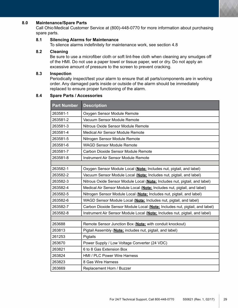
8.0 Maintenance/Spare Parts Call Ohio Medical Customer Service at (800)-448-0770 for more information about purchasing spare parts. 8.1 Silencing Alarms for Maintenance To silence alarms indefinitely for maintenance work, see section 4.8 8.2 Cleaning Be sure to use a microfiber cloth or soft lint-free cloth when cleaning any smudges off of the HMI. Do not use a paper towel or tissue paper, wet or dry. Do not apply an excessive amount of pressure to the screen to prevent cracking. 8.3 Inspection Periodically inspect/test your alarm to ensure that all parts/components are in working order. Any damaged parts inside or outside of the alarm should be immediately replaced to ensure proper functioning of the alarm.
8.4 Spare Parts / Accessories
Part Number Description
263581-1 Oxygen Sensor Module Remote263581-2 Vacuum Sensor Module Remote263581-3 Nitrous Oxide Sensor Module Remote263581-4 Medical Air Sensor Module Remote263581-5 Nitrogen Sensor Module Remote263581-6 WAGD Sensor Module Remote263581-7 Carbon Dioxide Sensor Module Remote263581-8 Instrument Air Sensor Module Remote
263582-1 Oxygen Sensor Module Local (Note: Includes nut, pigtail, and label)263582-2 Vacuum Sensor Module Local (Note: Includes nut, pigtail, and label)263582-3 Nitrous Oxide Sensor Module Local (Note: Includes nut, pigtail, and label)263582-4 Medical Air Sensor Module Local (Note: Includes nut, pigtail, and label)263582-5 Nitrogen Sensor Module Local (Note: Includes nut, pigtail, and label)263582-6 WAGD Sensor Module Local (Note: Includes nut, pigtail, and label)263582-7 Carbon Dioxide Sensor Module Local (Note: Includes nut, pigtail, and label)263582-8 Instrument Air Sensor Module Local (Note: Includes nut, pigtail, and label)
263688 Remote Sensor Junction Box (Note: with conduit knockout)263813 Pigtail Assembly (Note: includes nut, pigtail, and label)261253 Pigtails263670 Power Supply / Low Voltage Converter (24 VDC)263821 6 to 8 Gas Extension Box263824 HMI / PLC Power Wire Harness263823 8 Gas Wire Harness263669 Replacement Horn / Buzzer

550621 (Rev. 1, 02/17) Ohio Medical® Medical Gas Color LCD Touch Screen Area Alarm Service Manual30
9.0 Troubleshooting The table below lists potential problems that the user may encounter when operating the Ohio Medical Gas Color LCD Touch Screen Area Alarm along with corresponding potential causes and solutions. If none of the below solutions work, please contact Ohio Medical Customer Service at (800)-448-0770.
Issue / Problem Potential Cause Solution / Corrective Action
No Power
AC Power to the unit not available
AC Power Cord not connected
Blown Fuse at Building Panel
Check the building’s primary electrical panel to ensure circuit breaker is ON
Power Supply Module fuse in OFF position
Check that the 2A circuit breaker for the alarm’s power supply is in the ON position (clicked in)
Manual reset required If loss of power, password manual restart may be required. See Section 4.1.
No Audible AlarmConnectors on back of horn loose
With the 2A circuit breaker in OFF position, check the connectors on the back of the alarm horn (Note: Alarm horn is located in the lower right hand corner of the box)
No LED power indicator illuminated on alarm front panel
AC power is not turned on
Check AC power sourceBlown
Blown power supply fuse Replace fuse
AC power wiring is not connected
Check AC entrance wiring at power supply terminals
Faulty power supply assembly
Replace power supply

For 24/7 Technical Support, Call 800-448-0770 550621 (Rev. 1, 02/17) 31
10.0 Alarm Diagrams and Part Identification / Locations:
10.1 Alarm Major Components
Wire Harnesses
Mounting Brackets
2 Amp Circuit Breaker
16 Pin Female Connector Plug
Wire Harnesses
Adjustable Horn
Power Supply
Wall Studs
Outside Metal Frame
HMIInput / Output (I/O) Module
Metal Hinge Assembly
Restraining Lanyard (Mounts to Box Assembly)

550621 (Rev. 1, 02/17) Ohio Medical® Medical Gas Color LCD Touch Screen Area Alarm Service Manual32
10.2 Terminal Strip - To Zone Locations
10.2.1 Single Zone Terminal Strip Locations: Pressing the Auto-Configuration button on the touch-screen will automatically configure the single zone.
10.2.2 Two Zone Terminal Strip Locations: Pressing the Auto-Configuration button on the touch-screen will automatically configure the two zone.
For 24/7 Technical Support, Call 800-448-0770 550621 (Rev. 1, 02/17) 33
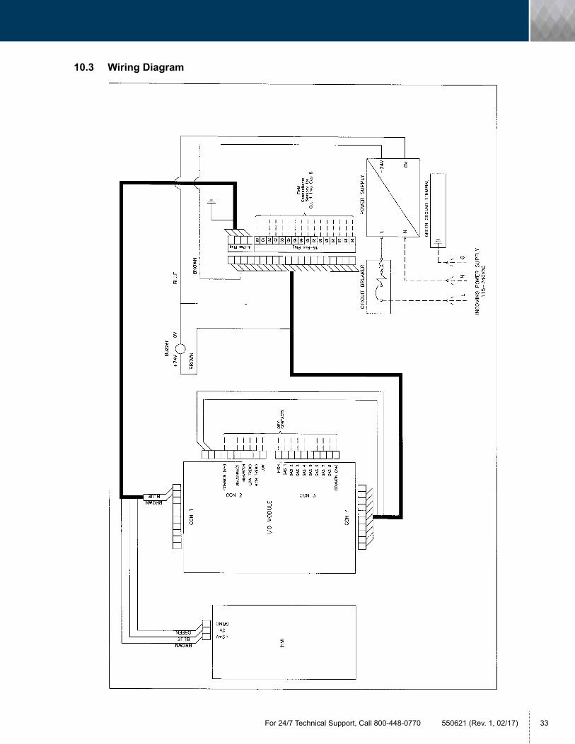
10.3 Wiring Diagram

© 2017 Ohio Medical, LLC. All rights reserved.
This document contains information that is proprietary and confidential to Ohio Medical, LLC. Use of this information is under license from Ohio Medical, LLC. Any use other than that authorized by Ohio Medical, LLC is prohibited. Ohio Medical and the Ohio Medical logo are registered trademarks of Ohio Medical, LLC. Amvex and the Amvex logo are registered trademarks of Ohio Medical, LLC. NFPA is a registered trademark of the National Fire Protection Association.
1111 Lakeside DriveGurnee, IL 60031-4099Phone: 866.549.6446Fax: 847.855.6300www.ohiomedical.com
®
550621 (Rev. 1, 02/17)