medical image inpainting with rbf interpolation...
TRANSCRIPT
(IJACSA) International Journal of Advanced Computer Science and Applications,
Vol. 7, No. 8, 2016
91 | P a g e
www.ijacsa.thesai.org
Medical Image Inpainting with RBF Interpolation
Technique
Mashail Alsalamah*, Saad Amin
Faculty of Engineering and Computing, Coventry University, Priory St, Coventry CV1 5FB, United Kingdom
Abstract—Inpainting is a method for repairing damaged
images or to remove unwanted parts of an image. While this
process has been performed by professional artists in the past,
today, the use of this technology is emerging in the medical area –
especially in the medical imaging realm. In this study, the
proposed inpainting method uses a radial basis function (RBF)
interpolation technique. We first explain radial basis functions
and then, the RBF interpolation system. This technique generally
depends on matrix processes. Thus, matrix operations are
executed after the interpolation and form a main part of the
process. This interpolation matrix has a known value used for
interpolating n values and we need to find M – 1 for the n + 1
values of the original and inserted data. Implementation of an
inpainting operation is carried out in an object-oriented
programming (OOP) language. This is where the process is
completed. The algorithm used in this study has a graphical user
interface. Further, several skin images are used for testing this
system. The obtained output represents a high level of accuracy
that can support the validity of the proposed method.
Keywords—Inpainting; interpolate; texture synthesis; exemplar
texture inpainting; Radial Basis Function
I. INTRODUCTION
One of the most interesting problems in image processing is reconstructing damaged or incomplete images as much as possible. This problem is referred to in many papers [1,2]. The main question in reconstructing damaged images is, “What value was in a corrupted position and how can this be restored?”. One of the conditions for solving this problem is to have as much information as possible from the original image. Then, appropriate existing methods can use this information and try to reconstruct the missing information [1]. The amount of information retained from the original image is very important as the quality of the result depends on it. The radial basis function (RBF) method is based on the principle of variational implicit functions and can be used for the interpolation of scattered data, see data. The possibility of missing data restoration (image inpainting) by the RBF method was mentioned in [3]. The method was used for surface retouching and marginally for image inpainting [3].
Inpainting is a method to repair damaged images or to remove unwanted parts of an image. While this process has been performed by professional artists in the past, today the use of technology is emerging in the medical imagining realm.
Several mathematical algorithms are used for inpainting, such as Laplace’s equations [4], isoline [5], texture synthesis [6] and interpolation [7]. The popular graphics program Adobe Photoshop [2] has a feature called content-aware fill in
its CS5 version. This feature performs a type of inpainting with high efficiency and low latency. Another graphics program, GMP [8] which is an open-source project, contains an an inpainting plugin called Resynthesizer [1]. This plugin uses a texture synthesis method to perform the inpainting operation.
There are other software programs available for video inpainting, these programs in general provide object removal. Adobe After Effect [2] and Apple Final Cut Pro [8] software provides such a feature. The problem with Adobe After Effects is that it is prone to unnecessary crashing, which makes it difficult to operate or deal with as it needs to be reset frequently.
The RBF interpolation-based inpainting method performs interpolation instead of texture matching, just like the texture synthesis method [9]. Therefore, the focus of this paper is to explore the effective usage of inter-polation based RBF inpainting.
The objectives of this paper are as follows: first, inpainting with an RBF interpolation method, and not pattern matching; second, rapid completion of an inpainting process. Further, the developed method should yield a satisfactory or relatively high-quality result.
Moreover, the speed factor can be changed by finding new ways to complete the same task with a quicker implementation. Quality depends on how the calculation results are used and can be improved by combining them with other information from the source image.
II. INTERPOLATION
In mathematics, interpolation is carried out to find the missing parts of a number series. This number series is either simple or complex mathematical series.
To find the missing numbers of a series, if the mathematical function is known, by setting the appropriate parameters, we can find the missing parts along with their exact values. For example, assume that function f(x) = x2 is known and some values are missing in the following series: 0, 1, 4, a, b, 25, c, 49. For x = 1, the result is 1; x = 3 would give 9. Therefore, a = 3. Similarly, by substituting x with 4 and 6, we obtain b = 16 and c = 36, and thus, the interpolation is completed.
However, sometimes, it is almost impossible to figure out the function of a number series [10].
(IJACSA) International Journal of Advanced Computer Science and Applications,
Vol. 7, No. 8, 2016
92 | P a g e
www.ijacsa.thesai.org
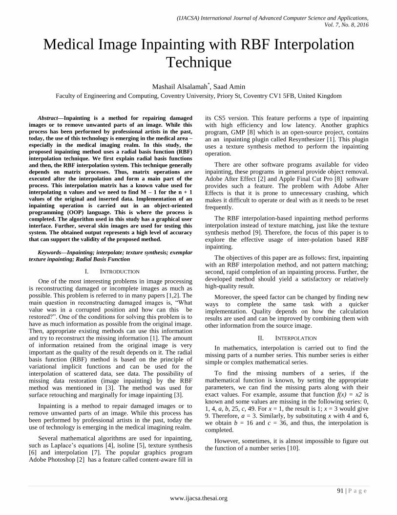
In this situation, missing values can only be found by using certain known values. The RBF interpolation method is used in such a case. RBF interpolation uses values in series and the distances between these values to create a base function structure. All missing parts can be found one by one by using the base function as in [11].
In digital imagery, each pixel is defined by a mixture of red, green, and blue colors. The RBF interpolation method is completely compatible with the RGB structure shown in [9]. Therefore, the problem with the interpolation system is that it is not perfect. It cannot ultimately find exact values; only estimated ones. Because of this reason, this method cannot yield perfect inpainting results. However, using interpolated values in a different way can enhance the quality of the results.
Fig. 1. Curve fitting
III. IMAGE INPAINTING
Inpainting is the process of reconstructing lost or deteriorated parts of images and videos. For instance, in the case of a valuable painting, this task will be carried out by a skilled image restoration artist. In the digital world, inpainting (also known as image interpolation or video interpolation) refers to the application of sophisticated algorithms to replace lost or corrupted parts of the image data (mainly small regions) or to remove small defects [11].
In Figure 2, an inpainting process is shown on an old photo. The output is very good, and almost all the lost parts are repaired.
Fig. 2. Old photo inpainting
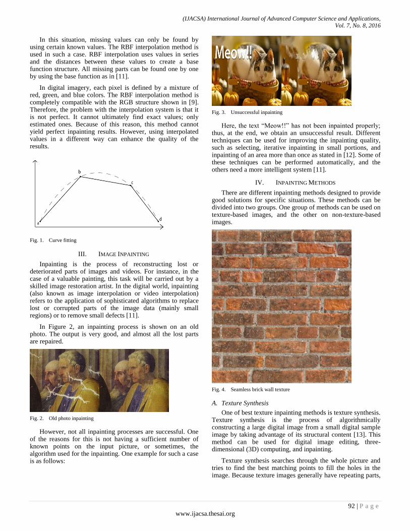
However, not all inpainting processes are successful. One of the reasons for this is not having a sufficient number of known points on the input picture, or sometimes, the algorithm used for the inpainting. One example for such a case is as follows:
Fig. 3. Unsuccessful inpainting
Here, the text “Meow!!” has not been inpainted properly; thus, at the end, we obtain an unsuccessful result. Different techniques can be used for improving the inpainting quality, such as selecting, iterative inpainting in small portions, and inpainting of an area more than once as stated in [12]. Some of these techniques can be performed automatically, and the others need a more intelligent system [11].
IV. INPAINTING METHODS
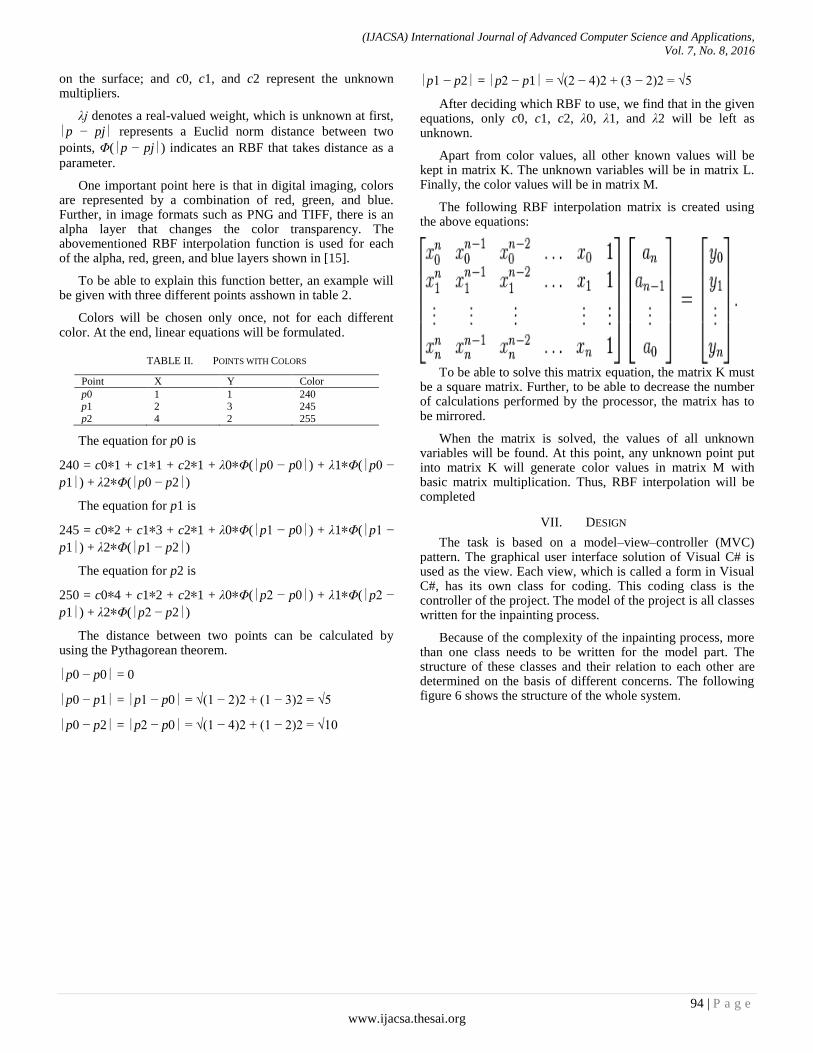
There are different inpainting methods designed to provide good solutions for specific situations. These methods can be divided into two groups. One group of methods can be used on texture-based images, and the other on non-texture-based images.
Fig. 4. Seamless brick wall texture
A. Texture Synthesis
One of best texture inpainting methods is texture synthesis. Texture synthesis is the process of algorithmically constructing a large digital image from a small digital sample image by taking advantage of its structural content [13]. This method can be used for digital image editing, three-dimensional (3D) computing, and inpainting.
Texture synthesis searches through the whole picture and tries to find the best matching points to fill the holes in the image. Because texture images generally have repeating parts,

(IJACSA) International Journal of Advanced Computer Science and Applications,
Vol. 7, No. 8, 2016
93 | P a g e
www.ijacsa.thesai.org
at the end, a seamless image is generated as demonstrated in [2].
B. Exemplar-Based Inpainting
Another method is exemplar-based inpainting. This method uses a texture synthesis algorithm and gives a higher priority to linear structures. Therefore, this is perceived that it gives better results: Linear structures are preserved, and no blurring occurs as shown in [12]. In the study, the RBF interpolation technique is used. RBF functions are also used for artificial intelligence systems as discussed in [11]. This shows that in a way this project uses an intelligent system to do inpainting. Inpainting with RBF is not used for texture-based or detailed images because of its blurry output.
The easiest way to explain interpolation is to find an unknown number in a series of numbers.
X = {1, 2, 3, a, 5, 6, b, 8, 9} In this number series, numbers are in an ascending order,
and the values of a and b are unknown. Interpolation is used for finding these unknown values by using the known numbers.
A more complicated example is to find more detailed points in a curve.
C. Convolution-based image inpainting algorithm
Convolution-based image inpainting algorithms as discussed in [5] are very fast. However, in many cases, they do not provide adequate results with respect to sharp details such as edges. In this method, the mask coefficients are calculated using the gradient of the image to be inpainted. The algorithm is fast, iterative, and simple to implement, and provides adequate results.
V. RADIAL BASIS FUNCTIONS (RBF)
An RBF is a real-valued function whose value depends only on the distance from the origin. RBFs are generally represented by the Φ (phi) symbol.
Fig. 5. Radial distances
In the above Figure 5, a center point and six other points connected to the center with a line are shown. An RBF takes the distance between any of these six points and the center and calculates a value.
Φ (distance) = Value of RBF. Distances from each point to the center are shown in table 1 below:
TABLE I. RBF POINTS AND DISTANCES
Point Distance to
center Point
Distance to
center
Point a 2 Point d 2
Point b 1 Point e 3
Point c 3 Point f 1
Irrespective of where the points are located in the space, as long as their distances to the center are equal, the results of the RBF are the same.
Thus, RBF (distance from point a to center) = RBF (distance from point d to center)
RBF (distance from point b to center) = RBF (distance from point f to center)
RBF (distance from point c to center) = RBF (distance from point e to center)
There are a number of functions that provide the attributes of an RBF.
Most simply, a linear RBF is Φ(r) = r [14]. Note: r denotes distance and thus, cannot be negative.
Another RBF is called Gaussian (GA). Its function is denoted as Φ(r) = e−(εr)2. This function is generally used in RBF networks for artificial intelligence systems. Further, this function will be implemented in this study to observe its effect on the inpainting process.
VI. RBF INTERPOLATION
RBF interpolation is matrix-based linear equation solving.
[K][L]=[M]
In this matrix equation, K denotes an n × n matrix, L represents an n × 1 matrix, and M indicates another n × 1 matrix.
The variable n denotes (number of known points + 3). The number 3 comes from (number of dimensions + 1). In this study, the considered image is two dimensional. Therefore, each point has only x and y coordinates. This implies that RBF interpolation can be applied to images that have more than two dimensions, as demonstrated in [12].
The definition of a point in RBF interpolation is given as a function as follows:
f (p) = q (p) + Σ j=0 n λ jΦ(∣p − pj∣)
This formula will be generated for each known point. In this formula, p denotes the current point in the list of known points, f(p) represents the color of point p, and q(p) denotes a
polynomial. Because this project uses 2D images, q(p) = c0∗x
+ c1∗y + c2∗1, where x and y represent the position of a point
(IJACSA) International Journal of Advanced Computer Science and Applications,
Vol. 7, No. 8, 2016
94 | P a g e
www.ijacsa.thesai.org
on the surface; and c0, c1, and c2 represent the unknown multipliers.
λj denotes a real-valued weight, which is unknown at first,
∣p − pj∣ represents a Euclid norm distance between two
points, Φ(∣p − pj∣) indicates an RBF that takes distance as a
parameter.
One important point here is that in digital imaging, colors are represented by a combination of red, green, and blue. Further, in image formats such as PNG and TIFF, there is an alpha layer that changes the color transparency. The abovementioned RBF interpolation function is used for each of the alpha, red, green, and blue layers shown in [15].
To be able to explain this function better, an example will be given with three different points asshown in table 2.
Colors will be chosen only once, not for each different color. At the end, linear equations will be formulated.
TABLE II. POINTS WITH COLORS
Point X Y Color
p0 1 1 240 p1 2 3 245
p2 4 2 255
The equation for p0 is
240 = c0∗1 + c1∗1 + c2∗1 + λ0∗Φ(∣p0 − p0∣) + λ1∗Φ(∣p0 −
p1∣) + λ2∗Φ(∣p0 − p2∣)
The equation for p1 is
245 = c0∗2 + c1∗3 + c2∗1 + λ0∗Φ(∣p1 − p0∣) + λ1∗Φ(∣p1 −
p1∣) + λ2∗Φ(∣p1 − p2∣)
The equation for p2 is
250 = c0∗4 + c1∗2 + c2∗1 + λ0∗Φ(∣p2 − p0∣) + λ1∗Φ(∣p2 −
p1∣) + λ2∗Φ(∣p2 − p2∣)
The distance between two points can be calculated by using the Pythagorean theorem.
∣p0 − p0∣ = 0
∣p0 − p1∣ = ∣p1 − p0∣ = √(1 − 2)2 + (1 − 3)2 = √5
∣p0 − p2∣ = ∣p2 − p0∣ = √(1 − 4)2 + (1 − 2)2 = √10
∣p1 − p2∣ = ∣p2 − p1∣ = √(2 − 4)2 + (3 − 2)2 = √5
After deciding which RBF to use, we find that in the given equations, only c0, c1, c2, λ0, λ1, and λ2 will be left as unknown.
Apart from color values, all other known values will be kept in matrix K. The unknown variables will be in matrix L. Finally, the color values will be in matrix M.
The following RBF interpolation matrix is created using the above equations:
To be able to solve this matrix equation, the matrix K must
be a square matrix. Further, to be able to decrease the number of calculations performed by the processor, the matrix has to be mirrored.
When the matrix is solved, the values of all unknown variables will be found. At this point, any unknown point put into matrix K will generate color values in matrix M with basic matrix multiplication. Thus, RBF interpolation will be completed
VII. DESIGN
The task is based on a model–view–controller (MVC) pattern. The graphical user interface solution of Visual C# is used as the view. Each view, which is called a form in Visual C#, has its own class for coding. This coding class is the controller of the project. The model of the project is all classes written for the inpainting process.
Because of the complexity of the inpainting process, more than one class needs to be written for the model part. The structure of these classes and their relation to each other are determined on the basis of different concerns. The following figure 6 shows the structure of the whole system.

(IJACSA) International Journal of Advanced Computer Science and Applications,
Vol. 7, No. 8, 2016
95 | P a g e
www.ijacsa.thesai.org
Fig. 6. System structure
The top part is used for presenting the view, the next row is the controller, and the rest contains the model classes. In this presentation, connections are drawn to show links between classes. These links are based on the usage of each other. Further, details increase from the top to the bottom and decrease from the bottom to the top, but in the latter case, the bindings increase as shown in [15].
In the fields of image processing and photography, a color histogram is a representation of the distribution of colors in an image. For digital images, a color histogram represents the number of pixels that have colors in each range of a fixed list of color ranges that span the image’s color space, the set of all possible colors.
The color histogram can be built for any type of color space, although the term is more often used for 3D spaces such as RGB and HSV. For monochromatic images, the term intensity histogram may be used instead. For multispectral images, where each pixel is represented by an arbitrary number of measurements (for example, beyond the three measurements in RGB), the color histogram is N-dimensional, with N being the number of measurements taken. Each measurement has its own wavelength range of the light spectrum, some of which may be outside the visible spectrum.
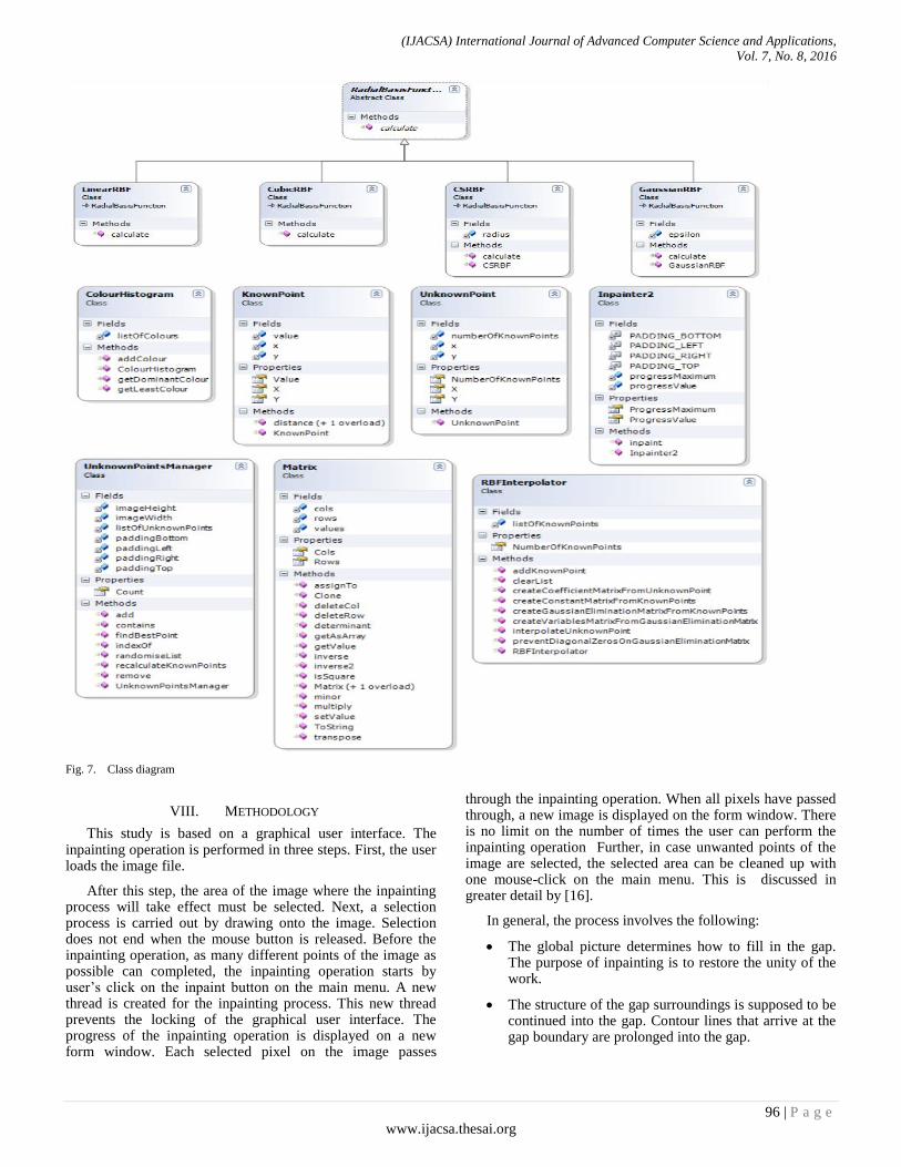
In the following Figure 7, all model classes are shown with their attributes and models. The details of each class are explained in the implementation part.
(IJACSA) International Journal of Advanced Computer Science and Applications,
Vol. 7, No. 8, 2016
96 | P a g e
www.ijacsa.thesai.org
Fig. 7. Class diagram
VIII. METHODOLOGY
This study is based on a graphical user interface. The inpainting operation is performed in three steps. First, the user loads the image file.
After this step, the area of the image where the inpainting process will take effect must be selected. Next, a selection process is carried out by drawing onto the image. Selection does not end when the mouse button is released. Before the inpainting operation, as many different points of the image as possible can completed, the inpainting operation starts by user’s click on the inpaint button on the main menu. A new thread is created for the inpainting process. This new thread prevents the locking of the graphical user interface. The progress of the inpainting operation is displayed on a new form window. Each selected pixel on the image passes
through the inpainting operation. When all pixels have passed through, a new image is displayed on the form window. There is no limit on the number of times the user can perform the inpainting operation Further, in case unwanted points of the image are selected, the selected area can be cleaned up with one mouse-click on the main menu. This is discussed in greater detail by [16].
In general, the process involves the following:
The global picture determines how to fill in the gap. The purpose of inpainting is to restore the unity of the work.
The structure of the gap surroundings is supposed to be continued into the gap. Contour lines that arrive at the gap boundary are prolonged into the gap.
(IJACSA) International Journal of Advanced Computer Science and Applications,
Vol. 7, No. 8, 2016
97 | P a g e
www.ijacsa.thesai.org
The different regions inside a gap, as defined by the contour lines, are filled with colors matching those of the gap boundary.
The small details are painted; i.e., “texture” is added.
IX. IMPLEMENTATION
In this study, we used Microsoft Visual Studio 2010. The steps for the implementation are such as starting a new project for a C# based .Net application.
A. Implementation of knownpoint class
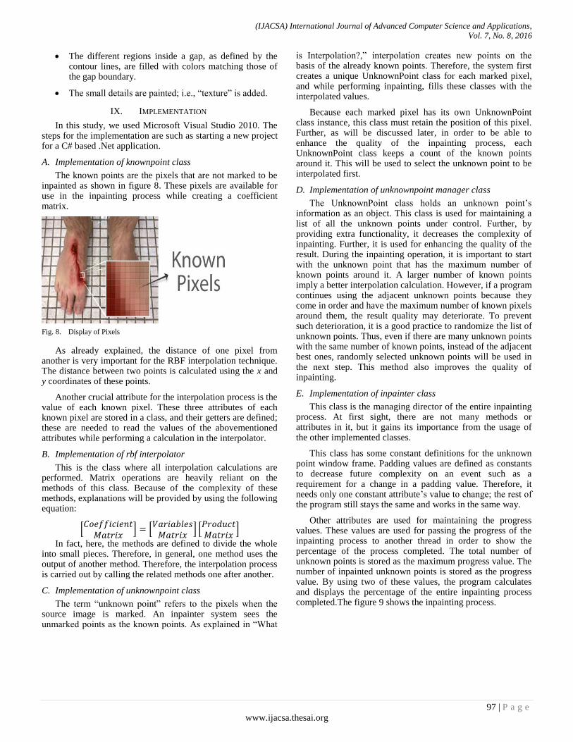
The known points are the pixels that are not marked to be inpainted as shown in figure 8. These pixels are available for use in the inpainting process while creating a coefficient matrix.
Fig. 8. Display of Pixels
As already explained, the distance of one pixel from another is very important for the RBF interpolation technique. The distance between two points is calculated using the x and y coordinates of these points.
Another crucial attribute for the interpolation process is the value of each known pixel. These three attributes of each known pixel are stored in a class, and their getters are defined; these are needed to read the values of the abovementioned attributes while performing a calculation in the interpolator.
B. Implementation of rbf interpolator
This is the class where all interpolation calculations are performed. Matrix operations are heavily reliant on the methods of this class. Because of the complexity of these methods, explanations will be provided by using the following equation:
[
] [
] [
]
In fact, here, the methods are defined to divide the whole into small pieces. Therefore, in general, one method uses the output of another method. Therefore, the interpolation process is carried out by calling the related methods one after another.
C. Implementation of unknownpoint class
The term “unknown point” refers to the pixels when the source image is marked. An inpainter system sees the unmarked points as the known points. As explained in “What
is Interpolation?,” interpolation creates new points on the basis of the already known points. Therefore, the system first creates a unique UnknownPoint class for each marked pixel, and while performing inpainting, fills these classes with the interpolated values.
Because each marked pixel has its own UnknownPoint class instance, this class must retain the position of this pixel. Further, as will be discussed later, in order to be able to enhance the quality of the inpainting process, each UnknownPoint class keeps a count of the known points around it. This will be used to select the unknown point to be interpolated first.
D. Implementation of unknownpoint manager class
The UnknownPoint class holds an unknown point’s information as an object. This class is used for maintaining a list of all the unknown points under control. Further, by providing extra functionality, it decreases the complexity of inpainting. Further, it is used for enhancing the quality of the result. During the inpainting operation, it is important to start with the unknown point that has the maximum number of known points around it. A larger number of known points imply a better interpolation calculation. However, if a program continues using the adjacent unknown points because they come in order and have the maximum number of known pixels around them, the result quality may deteriorate. To prevent such deterioration, it is a good practice to randomize the list of unknown points. Thus, even if there are many unknown points with the same number of known points, instead of the adjacent best ones, randomly selected unknown points will be used in the next step. This method also improves the quality of inpainting.
E. Implementation of inpainter class
This class is the managing director of the entire inpainting process. At first sight, there are not many methods or attributes in it, but it gains its importance from the usage of the other implemented classes.
This class has some constant definitions for the unknown point window frame. Padding values are defined as constants to decrease future complexity on an event such as a requirement for a change in a padding value. Therefore, it needs only one constant attribute’s value to change; the rest of the program still stays the same and works in the same way.
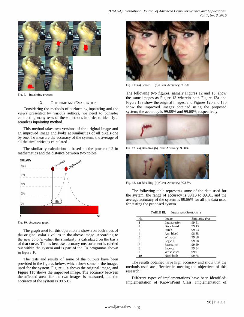
Other attributes are used for maintaining the progress values. These values are used for passing the progress of the inpainting process to another thread in order to show the percentage of the process completed. The total number of unknown points is stored as the maximum progress value. The number of inpainted unknown points is stored as the progress value. By using two of these values, the program calculates and displays the percentage of the entire inpainting process completed.The figure 9 shows the inpainting process.
(IJACSA) International Journal of Advanced Computer Science and Applications,
Vol. 7, No. 8, 2016
98 | P a g e
www.ijacsa.thesai.org
Fig. 9. Inpainting process
X. OUTCOME AND EVALUATION
Considering the methods of performing inpainting and the views presented by various authors, we need to consider conducting many tests of these methods in order to identify a seamless inpainting method.
This method takes two versions of the original image and an improved image and looks at similarities of all pixels one by one. To measure the accuracy of the system, the average of all the similarities is calculated.
The similarity calculation is based on the power of 2 in mathematics and the distance between two colors.
Fig. 10. Accuracy graph
The graph used for this operation is shown on both sides of the original color’s values in the above image. According to the new color’s value, the similarity is calculated on the basis of that curve. This is because accuracy measurement is carried out within the system and is part of the C# programas shown in figure 10.
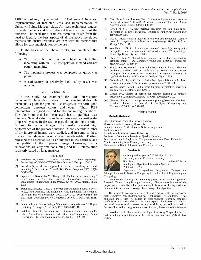
The tests and results of some of the outputs have been provided in the figures below, which show some of the images used for the system. Figure 11a shows the original image, and Figure 11b shows the improved image. The accuracy between the affected areas for the two images is measured, and the accuracy of the system is 99.59%
Fig. 11. (a) Scared (b) Clear Accuracy: 99.5%
The following two figures, namely Figures 12 and 13, show
the same images as Figure 13 wherein both Figure 12a and
Figure 13a show the original images, and Figures 12b and 13b
show the improved images obtained using the proposed
system; the accuracy is 99.88% and 99.68%, respectively.
Fig. 12. (a) Bleeding (b) Clear Accuracy: 99.8%
Fig. 13. (a) Bleeding (b) Clear Accuracy: 99.68%
The following table represents some of the data used for the system; the range of accuracy is 99.13 to 99.91, and the average accuracy of the system is 99.56% for all the data used for testing the proposed system.
TABLE III. IMAGE AND SIMILARITY
No. Image Similarity (%)
1 Leg abrasion 99.51 2 Back bleed 99.13
3 Stitch 99.63
4 Arm bleed 98.88
5 Wrist cut 99.68
6 Leg cut 99.68
7 Face stitch 99.59 8 Face cut 99.84
9 Wrist stitch 99.91
10 Neck boils 99.75
The results obtained have high accuracy and show that the methods used are effective in meeting the objectives of this research.
Different types of implementations have been identified: Implementation of KnownPoint Class, Implementation of
(IJACSA) International Journal of Advanced Computer Science and Applications,
Vol. 7, No. 8, 2016
99 | P a g e
www.ijacsa.thesai.org
RBF Interpolator, Implementation of Unknown Point class, Implementation of Inpainter Class, and Implementation of Unknown Points Manager class. All these techniques suggest disparate methods and thus, different levels of quality of the outcome. The need for a seamless technique arises from the need to identify the best aspects of all the above mentioned methods and ensure that these are used with an interface that allows for easy manipulation by the user.
On the basis of the above results, we concluded the following:
This research met the set objectives including inpainting with an RBF interpolation method and not pattern matching.
The inpainting process was completed as quickly as possible.
A satisfactory or relatively high-quality result was obtained.
XI. CONCLUSION
In this study, we examined the RBF interpolation technique for inpainting images. It has been found that this technique is good for gradient-like images. It can form good connections between colors and edges. Thus, RBF interpolation is a good method for skin inpainting operations. The algorithm that has been used has a graphical user interface. Several skin images have been used for testing the proposed system. In the testing part, the inpainting operation is used for wound images. The results revealed high performance of the proposed method. A considerable number of the improved images were studied, and in some of these images, the damage was almost unnoticeable. Further, repeating the operation led to an increase in the accuracy and the quality of the improved image. However, matrix calculations are very time consuming, and RBF interpolation is directly based on large matrices.
REFERENCES
[1] Bertalmío M, Sapiro G, Caselles, Ballester C. “Image inpainting.” Proceedings of SIGGRAPH’2000, New Orleans, 2000, pp. 417–424.
[2] Kozhekin N, et al. “An approach to surface retouching and mesh smoothing.” International Journal: The Visual Computer 2003; 19(7–8):549–564.
[3] Kojekine N, Savchenko V. “Using CSRBFs for surface retouching.” Proceedings of The 2nd IASTED International Conference Visualization, Imaging and Image Processing VIIP 2002, Malaga, Spain, 2002.
[4] Bertalmio, Marcelo, Andrea L. Bertozzi, and Guillermo Sapiro. "Navier-stokes, fluid dynamics, and image and video inpainting." In Computer Vision and Pattern Recognition, 2001. CVPR 2001. Proceedings of the 2001 IEEE Computer Society Conference on, vol. 1, pp. I-355. IEEE, 2001.
[5] Nauta, Jelle, and Sander Feringa. "Qualitative Comparison of 2D Digital Inpainting Techniques." 10th SC@ RUG 2012-2013: 18.
[6] Bertalmio, Marcelo, Luminita Vese, Guillermo Sapiro, and Stanley Osher. "Simultaneous structure and texture image inpainting." Image Processing, IEEE Transactions on 12, no. 8 (2003): 882-889.
[7] Chan, Tony F., and Jianhong Shen. "Nontexture inpainting by curvature-driven diffusions." Journal of Visual Communication and Image Representation 12, no. 4 (2001): 436-449.
[8] Powell M J D. “A new iterative algorithm for thin plate spline interpolation in two dimensions.” Annals of Numerical Mathematics 1997;4:519–527.
[9] Iske A. “Multiresolution methods in scattered data modelling.” Lecture notes in computational science and engineering. Berlin: Springer Verlag; 2004, p. 37.
[10] Wendland H. “Scattered data approximation”, Cambridge monographs on applied and computational mathematics, Vol. 17. Cambridge: Cambridge University Press; 2005.
[11] Uhlir K, Skala V. “Radial basis function use for the restoration of damaged images.” In: Computer vision and graphics, Dordrecht: Springer; 2006, p. 839–844.
[12] Shu C, Ding H, Yeo KS.” Local radial basis function-based differential quadrature method and its application to solve two-dimensional incompressible Navier–Stokes equations.” Computer Methods in Applied Mechanics and Engineering 2003;192(7):941–954.
[13] Golitschek M, Light W. “Interpolation by polynomials and radial basis functions on spheres.” Constructive Approximation 2000;17:1–18.
[14] Wright, Grady Barrett. "Radial basis function interpolation: numerical and analytical developments.” (2003).
[15] Genton MC. Classes of kernels for machine learning: A statistics perspective. J. Machine Learning Research, 2001;2:299–312.
[16] Shen M, Chen J, Li B. Image piecewise inpainting based on radial basis function. “International Journal of Intelligent Computing and Cybernetics” 2008;1(4):537–548.
AUTHOR PROFILE
Mashail Alsalamah
Current position, grades:PhD research student University studies:Coventry University
Scientific interest: Artifical Neural Network,Algorithm.
Publications <3>: Experience:a lecture at Qassim University .
Bachelor in Computer science from Qassim University.
Diploma in acadmic English and Computer science from Essex University Msc in Computing from Coventry University.
PhD student in Health Informatics at Coventry University.
Saad Amin
Current position, grades:PhD Principal Lecture University studies:Coventry University
Scientific interest:Artifical Intelligence,Algorithm,Information System.
Publications <79>:
Experience: Post-graduate Programme Manager and Principal Lecturer in Network Computing in the Faculty of Engineering and
Computing.
Involved with a European Community project at the Parallel Algorithms Research Centre, Loughborough University. The main objectives of the project were to establish a European standard platform for the exploration of biocomputational, nanotechnological and holographic algorithms.
The principal investigator of several funded projects. He has supervised eight completed PhD students and has eight current PhD students. He has published more than 70 papers in peer-reviewed journals, reputable conferences and books chapters on many aspects of this research. He has organised international conferences and workshops, as well as acted as Session Chair and on program committees for many international conferences.
Served on the IEEE Committee for Signal Processing Chapter for the UK and Ireland and Vice-Chairman of the British Computer Society/Middle East section.