medium-frequency induction melting furnace as a load on the power system
TRANSCRIPT

8/10/2019 Medium-Frequency Induction Melting Furnace as a Load on the Power System
http://slidepdf.com/reader/full/medium-frequency-induction-melting-furnace-as-a-load-on-the-power-system 1/12
IEEE TRANSACTIONS ON INDUSTRY APPLICATIONS, VOL. 48, NO. 4, JULY/AUGUST 2012 1203
Medium-Frequency Induction Melting Furnaceas a Load on the Power System
Ilker Yılmaz, Muammer Ermis, Member, IEEE , and Isık Çadırcı, Member, IEEE
Abstract—The variable-frequency operation of the coreless in-duction melting furnace (IMF) has been investigated in detailboth theoretically and experimentally. The time variations of theoperational impedance value of the IMF, owing to the time-varyingresonance frequency and crucible conditions, have been derivedfor typical melting cycles by using a variable parallel RLC modelderived from extensive field measurements. The work coil andits crucible are supplied at variable frequency from a multi-pulse rectifier and a current-fed load-resonant inverter cascade.Uncharacteristic current harmonics caused by cross-modulationphenomenon across the alternating current ac–dc–ac link havebeen derived theoretically and verified by field tests. These theo-
retical results and extensive field measurements on a sample IMFinstallation have shown the following: 1) The major power qualityproblem of an IMF as a load on the power system is the injectionof various characteristic and uncharacteristic current harmonicsto the grid; 2) line currents on the supply side are nearly balanced;3) flicker contribution is below the limits specified in the stan-dards; 4) reactive power demand is relatively low and the varia-tions in the magnitude and rate of change of active power are notdrastic; and 5) no voltage sag and swell phenomena arising fromfurnace operation occur.
Index Terms—Harmonic analysis, induction melting furnaces,power conversion harmonics, power quality.
I. INTRODUCTION
T HE induction melting furnace (IMF) offers a clean,energy-efficient, and easily controllable melting process
for both ferrous and nonferrous materials, as compared to othermeans of metal melting [1]–[4]. It has competitive installationcosts and relatively low running costs for small steel melt shops.
Manuscript received June 29, 2011; revised October 28, 2011; acceptedFebruary 17, 2012. Date of publication May 30, 2012; date of current ver-sion July 13, 2012. Paper 2011-METC-283.R1, presented at the 2011 IEEEIndustry Applications Society Annual Meeting, Orlando, FL, October 9–13,and approved for publication in the IEEE TRANSACTIONS ON INDUSTRY
APPLICATIONS by the Metals Industry Committee of the IEEE Industry
Applications Society.I. Yılmaz is with the Department of Electrical and Electronics En-
gineering, Middle East Technical University, Ankara 06531, Turkey, andalso with the Power Electronics Department, Space Technologies ResearchInstitute (UZAY), The Scientific and Technological Research Council of Turkey (TÜBITAK), Ankara 06531, Turkey (e-mail: [email protected]).
M. Ermis is with the Department of Electrical and Electronics Engineering,Middle East Technical University, Ankara 06531, Turkey (e-mail [email protected]).
I. Çadırcı was with the Power Electronics Department, Space TechnologiesResearch Institute (UZAY), The Scientific and Technological Research Councilof Turkey (TÜBITAK), Ankara 06531, Turkey. She is now with HacettepeUniversity, Ankara 06800, Turkey (e-mail: [email protected]).
Color versions of one or more of the figures in this paper are available onlineat http://ieeexplore.ieee.org.
Digital Object Identifier 10.1109/TIA.2012.2199457
Among various types of IMFs, the medium-frequency corelessIMFs have shown a growing interest in small steel melt shopsand alloy steel plants, due to their significantly reduced capitalcost for a given melting rate. This is due to the developmentof high-power-density IMF fed from solid-state inverters oper-ating at medium frequency. Also, the inherent surface stirringaction assisting with the dissolution of alloy additions or newlyadded charge materials represents an additional benefit of IMF[1], [2], [4].
Resonant load inverters have been designed to allow the
output power frequency to change during a melting cycle, inorder to maintain tuning to the natural frequency of the workcoil [1], [4], [5]. The power applied to the IMF depends only onthe limits of the inverter voltages and currents; these are chosento allow substantially constant power input to be achievedthrough the melting of a cold charge, the load conditions of which change during the total melting cycle [4]. The operatingpower and frequency of medium-frequency coreless IMF are inthe ranges of 10 kW–15 MW and 150–250 Hz, respectively, upto 40-t capacity.
Although the IMF has several advantages as described pre-viously, it constitutes one of the most problematic loads for thepower system, from the viewpoint of electric power quality. The
changing resonant frequency of the work coil during meltingperiod accentuates further the problem, due to the time-varyingnature of current harmonic orders and magnitudes injected tothe grid.
The basic characteristics of the IMF have been described,and the impact of injected interharmonics on the distributionsystem has been discussed in [6] and [7]. The utility voltagewaveform distortion arising from currents drawn by moderninduction furnaces has been described in [8]. However, thetime-varying nature of these harmonics and interharmonics interms of harmonic orders and magnitudes has not been assessedin detail in the literature.
In this paper, the variable-frequency operation of the core-less IMF has been represented by a time-varying parallelRLC circuit model, derived from field measurements takenfor typical melting cycles. The power quality parameters of the coreless medium-frequency IMF have been investigated indetail according to International Electrotechnical Commission(IEC) Standard 61000-4-30 [9], and the adverse effects of theIMF system on the utility grid have been demonstrated byactual field tests. In particular, in addition to the characteristicharmonics, the time-varying uncharacteristic harmonics causedby cross-modulation phenomenon across the alternating current(ac)–dc–ac link of the multipulse rectifier and current-fed load-resonant inverter cascade have been derived theoretically and
0093-9994/$31.00 © 2012 IEEE

8/10/2019 Medium-Frequency Induction Melting Furnace as a Load on the Power System
http://slidepdf.com/reader/full/medium-frequency-induction-melting-furnace-as-a-load-on-the-power-system 2/12
1204 IEEE TRANSACTIONS ON INDUSTRY APPLICATIONS, VOL. 48, NO. 4, JULY/AUGUST 2012
Fig. 1. Simplified power circuit diagram of a typical medium-frequency coreless IMF.
then verified by extensive field tests carried out on an actualIMF system.
II. SYSTEM DESCRIPTION
The simplified power circuit diagram of a typical medium-frequency coreless IMF is as shown in Fig. 1. The IMF issupplied at variable frequency during the melting period via aload-resonant single-phase H-bridge inverter circuit, in order tomaximize the power transferred to the work coil. In order tomaintain the resonance condition, a resonant capacitor bank isconnected across the work coil terminals.
In order to approximate the dc-link current to a level currentand, hence, the work coil current to a rectangular currentwaveform, a large dc choke is placed in the dc link. The dcchoke also serves as a current-limiting reactor against faults onthe inverter side.
The dc link is usually fed from a 12-pulse controlled rectifiercircuit in order to minimize the following: 1) reactive powerdemand of the rectifier; 2) harmonic content of the ac sourcecurrents; and 3) harmonic content of the rectifier output voltage.The line-commutated 12-pulse rectifier system is formed byusing a three-phase ∆–∆/Y transformer bank and two six-pulse bridge rectifiers connected in series. To improve theharmonic content of the supply-side current waveforms, twoof such IMF systems are operated in a coordinated manner inthe same melt shop. This will also double the steel productioncapacity of the melt shop.
The operation of the IMF system shown in Fig. 1 is de-scribed, and its effects on the utility grid are discussed in the
next sections, both theoretically and experimentally. For thispurpose, field data collected from a sample IMF system areused. The measurement points are marked by gray-coloredsymbol MP in Fig. 1.
III. VARIABLE-FREQUENCY OPERATION OF IMF
A. Field Measurements
Field data are collected on a 25-t 12-MVA IMF system forseveral melting cycles at measurement points MP1–MP4 inFig. 1, by using a custom-designed power quality measurementsystem which is programmed to collect raw data [10]. Each
voltage and current quantity is sampled at a rate of 12.8 kS/swith time synchronization. At MP1, voltage and current signals
Fig. 2. Supply voltage and current waveforms measured at MP1.
Fig. 3. DC-link voltage and ac component of dc-link current waveformsmeasured at MP2.
are taken from secondaries of conventional current and volt-age transformers. At MP2–MP4, voltage signals are taken bythe use of high-voltage active differential probes, and currentsignals are taken by the use of Rogowski coils. The meanvalue of the dc-link current is calculated from the raw data,by data processing. All collected data are then postprocessedusing a dedicated power quality software [10], according to IECStandard 61000-4-30 [9].
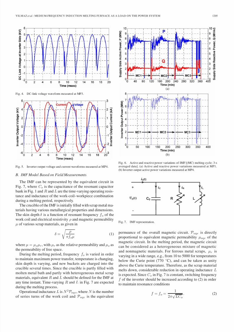
Some sample records of currents and voltages at measure-ment points MP1–MP4 are shown in Figs. 2–5, respectively.The active and reactive power variations of IMF at MP1 and
MP4 are also shown for a few typical melting cycles in Fig. 6(a)and (b), respectively.
8/10/2019 Medium-Frequency Induction Melting Furnace as a Load on the Power System
http://slidepdf.com/reader/full/medium-frequency-induction-melting-furnace-as-a-load-on-the-power-system 3/12
YILMAZ et al.: MEDIUM-FREQUENCY INDUCTION MELTING FURNACE AS A LOAD ON THE POWER SYSTEM 1205
Fig. 4. DC-link voltage waveform measured at MP3.
Fig. 5. Inverter output voltage and current waveforms measured at MP4.
B. IMF Model Based on Field Measurements
The IMF can be represented by the equivalent circuit inFig. 7, where C o is the capacitance of the resonant capacitorbank in Fig. 1 and R and L are the time-varying operating resis-tance and inductance of the work-coil–workpiece combinationduring a melting period, respectively.
The crucible of the IMF is initially filled with scrap metal ma-terials having various metallurgical properties and dimensions.The skin depth δ is a function of resonant frequency f o of thework coil and electrical resistivity ρ and magnetic permeabilityµ of various scrap materials, as given in
δ =
ρπf oµ (1)
where µ = µoµr, with µr as the relative permeability and µo asthe permeability of free space.
During the melting period, frequency f o is varied in orderto maintain maximum power transfer, temperature is changing,skin depth is varying, and new buckets are charged into thecrucible several times. Since the crucible is partly filled withmolten metal bath and partly with heterogeneous metal scrapmaterials, equivalent R and L should be defined for the IMF atany time instant. Time-varying R and L in Fig. 7 are expectedduring the melting process.
Operational inductance L is N 2P eqv, where N is the numberof series turns of the work coil and P eqv is the equivalent
Fig. 6. Active and reactive power variations of IMF [(MC) melting cycle; 3-saveraged data]. (a) Active and reactive power variations measured at MP1.(b) Inverter output active power variations measured at MP4.
Fig. 7. IMF representation.
permeance of the overall magnetic circuit. P eqv is directlyproportional to equivalent magnetic permeability µeqv of themagnetic circuit. In the melting period, the magnetic circuitcan be considered as a heterogeneous mixture of magneticand nonmagnetic materials. For ferrous metal scraps, µr isvarying in a wide range, e.g., from 10 to 5000 for temperaturesbelow the Curie point (770 ◦C), and can be taken as unityabove the Curie temperature. Therefore, as the scrap materialmelts down, considerable reduction in operating inductance Lis expected. Since C o in Fig. 7 is constant, switching frequencyf of the inverter should be increased according to (2) in orderto maintain resonance conditions
f = f o = 12π
√ LC o
. (2)

8/10/2019 Medium-Frequency Induction Melting Furnace as a Load on the Power System
http://slidepdf.com/reader/full/medium-frequency-induction-melting-furnace-as-a-load-on-the-power-system 4/12

8/10/2019 Medium-Frequency Induction Melting Furnace as a Load on the Power System
http://slidepdf.com/reader/full/medium-frequency-induction-melting-furnace-as-a-load-on-the-power-system 5/12
YILMAZ et al.: MEDIUM-FREQUENCY INDUCTION MELTING FURNACE AS A LOAD ON THE POWER SYSTEM 1207
Fig. 11. Ideal coreless medium-frequency IMF system.
TABLE ICHARACTERISTIC HARMONICS OF THE IDEAL IMF SYSTEM
output current waveform of the inverter and found to varybetween 160 and 225 Hz. The variations in f o and f againsttime are shown in Fig. 10. It is seen from Fig. 10 that there is a
very good correlation between f o and f , and f is slightly higherthan f o, as expected.
IV. EXPRESSING THE HARMONICS
CAUSED BY THE IMF SYSTEM
A. Ideal IMF System
Fig. 11 shows the block diagram representation of an idealIMF installation. An ideal system means as follows: 1) The gridis an infinite bus; 2) transformer and power semiconductors inthe 12-pulse rectifier and H-bridge inverter are ideal devices;and 3) Ldc is an infinitely large inductance.
For the ideal system as shown in Fig. 11, the followingstatements are true.
1) IMF output voltage vL(t) and iL(t) would be a pure sinewave and a pure rectangular wave at resonance frequency,respectively.
2) vdc2(t) would be the fully rectified form of vL(t).3) idc(t) would be an ideal level current.4) vdc1(t) would be a 12-pulse rectified form of the supply
voltage waveforms.5) Line current waveforms on the supply side would be a
ten-step ac waveform at supply frequency.
The characteristic harmonics of an ideal IMF system are
given in Table I. The orders of current harmonics in supplylines are (12n ± 1) with respect to supply frequency, and their
magnitudes are 1/(12n ± 1) times the fundamental component,where n = 1, 2, 3, . . .. These harmonics do not comply withcurrent distortion limits given in IEEE Standard 519-1992 [11],
for general distribution systems. These could be successfullyfiltered out by passive tuned filters if the IMF installation werean ideal one. However, in practice, the harmonic content of supply line current waveforms is much richer than that of the ideal IMF installation owing to the cross-modulation phe-nomenon across the ac–dc–ac link. The orders of current har-monics on the load-resonant inverter output are (2k + 1) withrespect to the resonance frequency f o, and their magnitudes are1/(2k + 1) times that of the fundamental resonant current,where k = 1, 2, 3, . . .. These harmonics are then reflected tothe dc link with orders 2kf o, causing a cross modulation inthe supply line current harmonics in practice. The supply linecurrent harmonics arising from cross-modulation phenomenon
interact with the passive filter characteristics, thus making theuse of passive filtering techniques impracticable [6]. Theseissues will be discussed in the next section.
B. Practical IMF System
In the analysis of a practical IMF system, the sourceimpedance and the leakage impedance of the ∆/∆−Y cou-pling transformer should be taken into account. More importantthan this, the dc-link inductance is not sufficiently large toprevent the system from cross-modulation phenomenon. Crossmodulation in HVdc and variable-frequency ac motor drives
has been described in [12]. In these applications, both thesupply-side and the load-side converters are multipulse. How-

8/10/2019 Medium-Frequency Induction Melting Furnace as a Load on the Power System
http://slidepdf.com/reader/full/medium-frequency-induction-melting-furnace-as-a-load-on-the-power-system 6/12
1208 IEEE TRANSACTIONS ON INDUSTRY APPLICATIONS, VOL. 48, NO. 4, JULY/AUGUST 2012
TABLE IIINTERHARMONICS OF A PRACTICAL IMF SYSTEM ARISING FROM CROSS MODULATION
ever, for a practical IMF system, the load-side converter isa single-phase inverter, resulting in a much higher ac ripplecomponent on the dc-link voltage, and hence on the dc-linkcurrent, thus making the situation much more drastic than theaforementioned applications.
The dc-link current idc(t) in Figs. 1 and 11 is composed of its mean value I dc and its ac component idc(t). That is,
idc(t) = I dc + idc(t). (7)
Since the dc-link voltage on the rectifier side vdc1(t) is a12-pulse rectified voltage waveform and the dc-link voltageon the inverter side vdc2(t) is a two-pulse rectified voltagewaveform as shown in Fig. 11, then idc(t) can be expressedas in (8), by using the superposition principle, as the sum of theassociated ac current components
idc(t) =N n=1
I 12n sin[12n(2πf st) + θ12n]
+K k=1
sin [2k(2πf 0t) + θ2k] (8)
where I 12n is the peak value of the current harmonic driven bythe 12nth voltage harmonic of vdc1(t), I 2k is the peak valueof the current harmonic driven by the 2kth voltage harmonicof vdc2(t), θ12n and θ2k are the phase angles of the associatedharmonic current components with respect to the reference inthe Fourier series expansion, and K and N are the integers
corresponding to half of the sampling frequency.Harmonic components of idc(t) will be reflected to boththe load side and the supply side according to the switchingfunctions of single-phase inverter and 12-pulse rectifier topolo-gies. The switching function of the load-resonant single-phaseinverter can be expressed as in
F sw(inv)(t) =N n=1
4
π(2n − 1) sin[(2n − 1)(2πf 0t)] . (9)
Load current iL(t) is therefore the product of F sw(inv) andidc(t), as given in
iL(t) = F sw(inv)(t) × [I dc + idc(t)] . (10)
I dc causes the flow of the characteristic harmonics given inTable I on the load side, while idc(t) causes the flow of theuncharacteristic harmonics given in Table II. This phenomenonis known as the “cross modulation” in the literature [12].
In a similar manner, idc(t) is multiplied by the switching
function of the 12-pulse rectifier in (11), to obtain supply-sideharmonics of the IMF system. is(t) is therefore found by using(7), (8), (11), and (12), as given in (13)
F sw(rec)(t) =
4√
3
π sin[2πf st]
+N n=1
4√
3
π(12n−1) sin [(12n−1)(2πf st)]
+N
n=1
4√
3
π(12n−1)
sin [(12n+1)(2πf st)] (11)
is(t) =F sw(rec)(t) × [I dc+idc(t)] (12)
is(t) =F sw(rec)(t) × I dc
+N n=1
F sw(rec)(t)
×I 12n sin [12n(2πf st)+ θ12n]}
+K
k=1F sw(rec)(t)
× I 2k sin [2k(2πf st)+ θ2k]} . (13)
The first term in the right-hand side of (13) includes thefundamental component and only the characteristic harmoniccomponents of the 12-pulse rectifier, as expressed in the firstcolumn of Table I. The second term is due to the 12-pulsevoltage ripple in the dc link and contributes to the fundamen-tal component and characteristic current harmonics of is(t),depending on the value of phase angle θ12n. However, for apractical system, the effects of the 12nth harmonic currentcomponents in the dc link can be neglected. This is because
the relatively small magnitude of the 12nth voltage harmonicsof the rectifier can drive a small current through the relatively
8/10/2019 Medium-Frequency Induction Melting Furnace as a Load on the Power System
http://slidepdf.com/reader/full/medium-frequency-induction-melting-furnace-as-a-load-on-the-power-system 7/12

8/10/2019 Medium-Frequency Induction Melting Furnace as a Load on the Power System
http://slidepdf.com/reader/full/medium-frequency-induction-melting-furnace-as-a-load-on-the-power-system 8/12
1210 IEEE TRANSACTIONS ON INDUSTRY APPLICATIONS, VOL. 48, NO. 4, JULY/AUGUST 2012
Fig. 13. Harmonics of inverter current iL(t).
Fig. 14. Resonance frequency component of iL(t).
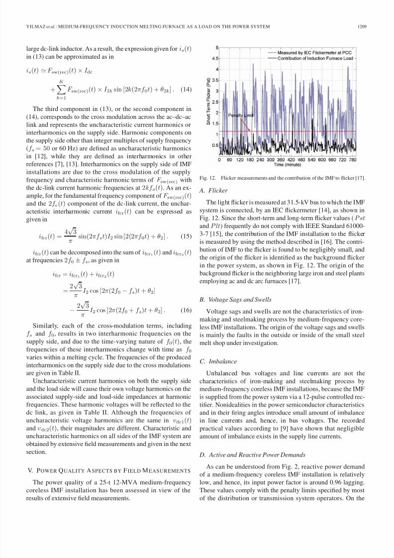
other hand, the fluctuations in the active power demand of theplant are considerable, particularly in the early phases of themelting cycle. However, their magnitudes and rate of changesare not as drastic as those of an ac arc furnace.
E. Harmonics
The raw data sampled at a rate of 12.8 kS/s/channel on thesupply side are postprocessed by fast Fourier transform (FFT)tool of the MATLAB, for ten-cycle-long windows to achieve a
5-Hz frequency resolution, as recommended in IEC 61000-4-7[13]. Consecutive FFT windows are nonoverlapping windows.However, on the load side, windows are 1 s long, thus achieving1-Hz frequency resolution. Time variations in the harmonicspectrum of the inverter output current waveform are shownin Fig. 13, for a typical melting cycle. The harmonics whichare apparent in Fig. 13 are the characteristic harmonics of theload side, as given in Table I. Uncharacteristic harmonics of theload side given in Table II do not appear in Fig. 13 since theirmagnitudes are negligibly small, as expected.
In order to make the variations in inverter switching fre-quency from 160 to 225 Hz more clear, Fig. 14 is drawn.Frequency spectra of dc-link voltage vdc1(t) and current idc(t)
are shown in Fig. 15(a) and (b), respectively, for the samemelting cycle.
Fig. 15. Harmonic spectra of dc-link quantities. (a) DC-link current idc(t).(b) DC-link voltage vdc1(t).
Uncharacteristic voltage harmonics in the dc link are verylow, while the corresponding current harmonics are negligiblysmall, so that they do not appear in Fig. 15(a).
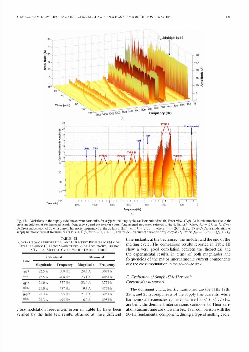
Time variations of the supply-side current harmonics andinterharmonics are shown by the frequency spectra in Fig. 16(a)and (b). Fig. 16(a) shows the magnitude variations for all har-monics and interharmonics for a typical melting cycle, whereasFig. 16(b) shows the characteristic harmonic currents (I 11, I 13,
I 23, I 25, etc.) separately from the uncharacteristic ones, due tothe cross-modulation phenomenon. Interharmonics at frequen-cies of (2f o ± f s), due to the cross modulation of the funda-mental supply frequency f s and the inverter output fundamentalfrequency referred to the dc link at 2f o, are indicated as Type Ain Fig. 16(b). The cross modulation of f s with current harmonicfrequencies at the dc link at 2kf o, with k = 2, 3, . . ., appears asinterharmonic frequencies at (2kf o ± f s), as indicated by TypeB in Fig. 16(b). The supply harmonic current frequencies due tothe 12-pulse rectifier operation, at frequencies of (12n ± 1)f s,for n = 1, 2, 3, . . ., and the current harmonic frequency at thedc link at 2f o cross modulate at frequencies of (12n ± 1)f s ±2f o, as indicated by Type C curves in Fig. 16(b).
The major interharmonic current magnitudes obtainedtheoretically in (15) and (16), at the corresponding
8/10/2019 Medium-Frequency Induction Melting Furnace as a Load on the Power System
http://slidepdf.com/reader/full/medium-frequency-induction-melting-furnace-as-a-load-on-the-power-system 9/12
YILMAZ et al.: MEDIUM-FREQUENCY INDUCTION MELTING FURNACE AS A LOAD ON THE POWER SYSTEM 1211
Fig. 16. Variations in the supply-side line current harmonics for a typical melting cycle. (a) Isometric view. (b) Front view. (Type A) Interharmonics due to thecross modulation of fundamental supply frequency f s and the inverter output fundamental frequency referred to the dc link 2f o, where f cr = 2f o ± f s. (TypeB) Cross modulation of f s with current harmonic frequencies at the dc link at 2kf o, with k = 2, 3, . . ., where f cr = 2kf o ± f s. (Type C) Cross modulation of supply harmonic current frequencies at (12n± 1)f s, for n = 1, 2, 3, . . ., and the dc-link current harmonic frequency at 2f o, where f cr = (12n± 1)f s ± 2f o.
TABLE IIICOMPARISON OF T HEORETICAL AND F IELD T EST RESULTS FOR MAJOR
INTERHARMONIC CURRENT MAGNITUDES AND FREQUENCIES DURINGA T YPICAL MELTING CYCLE W ITH 1-Hz RESOLUTION
cross-modulation frequencies given in Table II, have beenverified by the field test results obtained at three different
time instants, at the beginning, the middle, and the end of themelting cycle. The comparison results reported in Table IIIshow a very good correlation between the theoretical andthe experimental results, in terms of both magnitudes andfrequencies of the major interharmonic current componentsdue the cross modulation in the ac–dc–ac link.
F. Evaluation of Supply-Side Harmonic
Current Measurements
The dominant characteristic harmonics are the 11th, 13th,23th, and 25th components of the supply line currents, whileharmonics at frequencies 2f o ± f s, where 160 < f o < 225 Hz,are being the dominant interharmonic components. Their vari-
ations against time are shown in Fig. 17 in comparison with the50-Hz fundamental component, during a typical melting cycle.

8/10/2019 Medium-Frequency Induction Melting Furnace as a Load on the Power System
http://slidepdf.com/reader/full/medium-frequency-induction-melting-furnace-as-a-load-on-the-power-system 10/12
1212 IEEE TRANSACTIONS ON INDUSTRY APPLICATIONS, VOL. 48, NO. 4, JULY/AUGUST 2012
Fig. 17. Variations of dominant characteristic and uncharacteristic harmonicsduring a melting cycle (1-s averaged data).
Fig. 18. TDD of supply line currents versus time over a melting cycle.
Although the penalty limits for individual characteristic currentharmonic components are specified in various standards, noinformation has been found in the literature for interharmoniccomponents. It is seen from Fig. 17 that the individual char-acteristic harmonics do not comply with the limits specifiedin IEEE Standard 519-1992 [11]. The magnitudes of interhar-monics at frequencies (2f o ± 50 Hz) are higher than those of 550- and 650-Hz characteristic harmonic components andaround 10% of the fundamental component. These interhar-monic current components give rise to associated interharmonicvoltage components at the supply buses. Interharmonic voltage
distortion has to be restricted at values less than or equal to0.2% of the fundamental, in the planning phase, as recom-mended in IEC 1000-3-6 [18].
In this paper, the combined effects of interharmonic currentcomponents and characteristic harmonics will be assessed inthe sense of total demand distortion (TDD) limits specified instandards. The variations in TDD, including all harmonics, areas shown in Fig. 18, for a typical melting cycle. TDD limits forthe strongest and the weakest supply buses are also marked inthe same figure. It is seen from Fig. 18 that TDD exceeds thelimit value for most of the time, during a melting cycle, evenfor the strongest supply.
Interaction of the characteristic harmonics and interharmon-
ics in the supply line currents, arising from variable-frequencyoperation of the IMF, with the shunt passive filter banks con-
nected to the same bus is also investigated in this paper. For thispurpose, three different passive shunt harmonic filters (HFs) areconsidered as defined in the following:
1) fifth HF only;2) 11th HF + 13th HF;3) 5th HF + 7th HF + 11th HF + 13th HF.
Their characteristics are obtained by assuming that the qual-ity factor is 80 and the total installed capacity is 2 Mvar and arethen plotted in Fig. 19.
On the other hand, as can be understood from Fig. 16,frequency of the interharmonic components migrates on the fre-quency axis, as resonance frequency is increased during meltingperiod. As a consequence of this phenomenon, a considerableportion of the frequency range will be swept, as shown inFig. 19, throughout the melting cycle. As can be understoodfrom Fig. 19, at any time in a typical melting cycle, at leastone of the interharmonics will be amplified particularly by thefilters previously defined as 1) and 3). These HF combinationsdo not make any contribution to filtering action to comply withTDD limits given in IEEE Standard 519-1992 but lead to theamplification of interharmonics on the supply side. The HFtopology containing only the fifth HF will improve only theinput power factor of the steel melt shop to unity. Therefore, tomitigate the interharmonic problem, new technologies shouldbe exercised, such as active power filters and/or pulsewidthmodulation rectifiers.
VI. CONCLUSION
The medium-frequency coreless IMF supplied from a mul-tipulse rectifier and a single-phase load-resonant current-fed
inverter cascade has been investigated as a load on the powersystem. The variable-frequency operation of the IMF has beenrepresented by a variable RLC model, derived from extensivefield measurements carried out for typical melting cycles. Allpower quality parameters of the IMF system have been investi-gated according to the related standards, and it has been shownthat the major power quality problem for the utility grid is dueto the injection of time-varying interharmonic currents to thesupply.
The harmonic and interharmonic currents caused by the IMFsystem have been investigated in detail for both the ideal andthe practical systems, both theoretically and experimentally via
field tests. The frequencies and magnitudes of the uncharacter-istic harmonics and interharmonics caused by the cross modu-lation across the ac–dc–ac link have been derived theoreticallyfor a practical IMF operation. Different cross-modulation typeshave been shown to occur between harmonic frequencies of the supply current and those of inverter output current referredto the dc link, in practice. The theoretical findings have thenbeen verified by field tests, and it has been shown that the time-varying nature of the uncharacteristic harmonics and interhar-monics can be estimated quite accurately from the theoreticalderivations. The time-varying nature of the IMF resonancefrequency and, hence, the interharmonic currents caused bythe cross modulations have been illustrated by 3-D frequency
spectra in this paper. It has been shown that magnitudes andfrequencies of the supply current harmonics and interharmonics

8/10/2019 Medium-Frequency Induction Melting Furnace as a Load on the Power System
http://slidepdf.com/reader/full/medium-frequency-induction-melting-furnace-as-a-load-on-the-power-system 11/12
YILMAZ et al.: MEDIUM-FREQUENCY INDUCTION MELTING FURNACE AS A LOAD ON THE POWER SYSTEM 1213
Fig. 19. Illustration of the interaction between interharmonic current components of variable-frequency IMF installation and some typical passive shunt filtercombinations.
vary in a relatively wide range within a melting cycle and,hence, cannot be mitigated by passive filtering solutions.
APPENDIX
The inverter output power P w is considered to be equal to thepower dissipated in R, denoted by P R, by assuming lossless Land C o. The power relation for P R is found (4) and is given in(17). The rms value of the inverter voltage V w can be expressedby its harmonics V 1–V n, as given in (18). The relation betweenR and P w can then be obtained using (17) and (18), as given
in (5)P R = P R1 + P R2 + · · · + P n
= V 21
R +
V 22R
+ · · · + V 2n
R (17)
V 2w = V 21 + V 22 + · · · + V 2n . (18)
L can be calculated from KVL equations at the inverteroutput considering the fundamental components of the invertervoltage and current V w1 and I w1, respectively. L is derivedusing (19)–(21), as given in (6)
I C 1|θC =
V w1
j2πf C 0 (19)
I R1 = V w1
R (20)
I L1|θL = I w1|θw − I C 1|θC − I R1 (21)
where I w1 is the fundamental rms component of the inverteroutput current with a phase angle θw and I C 1, I L1, and I R1
are the fundamental currents through C 0, L, and R with phaseangles θC , θL, and zero, respectively.
ACKNOWLEDGMENT
The authors would like to thank Mega Metallurgy Companyfor the permission and support given to the field tests.
REFERENCES
[1] E. J. Davies and P. G. Simpson, “Induction heating for industry,” Electron.Power , vol. 25, no. 7, pp. 508–515, Jul. 1979.
[2] J. Davies and P. Simpson, Induction Heating Handbook . New York:McGraw-Hill, 1979.
[3] S. Zinn and S. L. Semiatin, Elements of Induction Heating: Design,Control and Applications. Materials Park, OH: ASM Int., 1988.
[4] C. J. Edgerley, L. Smith, and C. F. Wilford, “Electric metal melting—A review,” Power Eng. J., vol. 2, no. 2, pp. 83–92, Mar. 1988.
[5] F. P. Dawson and P. Jain, “A comparison of load commutated invertersystems for induction heating and melting applications,” IEEE Trans.Power Electron., vol. 6, no. 3, pp. 430–441, Jul. 1991.
[6] R. C. Dugan and L. E. Conrad, “Impact of induction furnace interhar-monics on distribution systems,” in Proc. IEEE Transm. Distrib. Conf.,Apr. 1999, vol. 2, pp. 791–796.
[7] R. C. Dugan, M. F. Granaghan, S. Santoso, and H. W. Beaty, ElectricalPower Systems Quality, 2nd ed. New York: McGraw-Hill, 2003.
[8] R. A. Jabbar, M. Akmal, M. A. Masood, M. Junaid, and M. F. Akram,“Voltage waveform distortion measurement caused by the current drawnby modern induction furnaces,” in Proc. Harmon. Qual. Power Conf.,2008, pp. 1–7.
[9] IEC Electromagnetic Compatibility: Testing and Measurement Techniques-Power Quality Measurement Methods, 2nd ed., IEC Std.61000-4-30, 2008.
[10] O. Salor, S. Buhan, O. Unsar, B. Boyrazo glu, E. Altıntas, T. Atalık,B. Haliloglu, T. Inan, A. Kalaycıoglu, A. Terciyanlı, A. Açık, T. Demirci,E. Özdemirci, I. Çadırcı, and M. Ermis, “Mobile monitoring system totake nationwide PQ measurements on electricity transmission systems,”
Measurement , vol. 42, no. 4, pp. 501–515, May 2009.[11] IEEE Recommended Practices and Requirements for Harmonic Control
in Electrical Power Systems, IEEE Std. 519-1992.[12] J. Arrilaga and N. R. Watson, Power System Harmonics, 2nd ed.
Hoboken, NJ: Wiley, 2003.[13] Testing and Measurement Techniques-General Guide on Harmonics and
Interharmonics Measurements and Instrumentation for Power SupplySystems and Equipment Connected Thereto, IEC Std. 61000-4-7, 2002,2.0 ed.
[14] Flickermeter—Functional and Design Specifications, IEC Std. 61000-4-15, 2003.
[15] Assessment of Emission Limits for the Connection of Fluctuating Instal-lations to MV, HV and EHV Power Systems, IEC Std. 61000-3-7, 2008,2nd ed.
[16] E. Altıntas, Ö. Salor, I. Çadırcı, and M. Ermis, “A new flicker contributiontracing method based on individual reactive current components of multi-ple EAFS at PCC,” IEEE Trans. Ind. Appl., vol. 46, no. 5, pp. 1746–1754,Sep./Oct. 2010.
[17] E. Altıntas, “Flicker source identification at a point of common couplingof the power system,” M.S. thesis, Middle East Tech. Univ., Ankara,
Turkey, May 2010.[18] Assessment of Emission Limits for Distorting Loads in MV and HV Power Systems, IEC Std. 1000-3-6, 1996.

8/10/2019 Medium-Frequency Induction Melting Furnace as a Load on the Power System
http://slidepdf.com/reader/full/medium-frequency-induction-melting-furnace-as-a-load-on-the-power-system 12/12
1214 IEEE TRANSACTIONS ON INDUSTRY APPLICATIONS, VOL. 48, NO. 4, JULY/AUGUST 2012
Ilker Yılmaz received the B.Sc. degree in electricaland electronics engineering from Middle East Tech-nical University, Ankara, Turkey, in 2008, where heis currently working toward the Ph.D. degree.
He is working on power quality improvementof induction melting furnaces. He is also currentlya Senior Researcher with the Power ElectronicsDepartment, Space Technologies Research Institute
(UZAY), The Scientific and Technological ResearchCouncil of Turkey (TUBITAK), Ankara. His areasof research include active power filters and Voltage
Source Converter-type static synchronous compensators.
Muammer Ermis (M’99) received the B.Sc., M.Sc.,and Ph.D. degrees in electrical engineering fromMiddle East Technical University (METU), Ankara,Turkey, in 1972, 1976, and 1982, respectively, andthe M.B.A. degree in production management fromAnkara Academy of Economic and Commercial Sci-ences, Ankara, in 1974.
He is currently a Professor of electrical engineer-ing in the Department of Electrical and ElectronicsEngineering, METU.
Dr. Ermis was a recipient of The Overseas Pre-mium Paper Award from the Institution of Electrical Engineers, U.K., in1992, and the 2000 Committee Prize Paper Award from the Power SystemsEngineering Committee of the IEEE Industry Applications Society. He was alsoa recipient of the 2003 IEEE Power Engineering Society Chapter OutstandingEngineer Award and the Outstanding Paper Award from the Metals IndustryCommittee of the IEEE Industry Applications Society in 2009.
Isık Çadırcı (M’98) received the B.Sc., M.Sc., andPh.D. degrees in electrical and electronics engineer-ing from Middle East Technical University, Ankara,Turkey, in 1987, 1988, and 1994, respectively.
From 2004 to 2011, she was the Head of thePower Electronics Department, Space TechnologiesResearch Institute (UZAY), The Scientific and Tech-nological Research Council of Turkey (TÜBITAK),
Ankara. She is currently a Professor of electricalengineering at Hacettepe University, Ankara. Herareas of interest include power quality, electric motor
drives, and switch-mode power supplies.Dr. Çadırcı was a recipient of the Committee Prize Paper Award from the
Power Systems Engineering Committee of the IEEE Industry ApplicationsSociety in 2000, the IEEE Industry Applications Magazine Prize Paper Award,Third Prize, in 2007, and the Outstanding Paper Award fromthe MetalsIndustryCommittee of the IEEE Industry Applications Society in 2009.