medium voltage products• iec 62271-1 for general purposes. • iec 62271-200 for the switchgear....
TRANSCRIPT

Medium Voltage ProductsMedium Voltage Products
Medium Voltage Products
UniGear ZS236 kV, 3150A, 31.5 kA Medium voltage, arc-proof, air insulated switchgear

2 2

3 3
Index
4 1. UniGear ZS26 Air-insulated8 IEC Classification10 Type-tested12 Arc-proof14 Safety16 Vacuum Circuit Breaker20 Gas Circuit Breaker22 Service Trucks24 Instrument Transformers26 Measurement sensors28 Distribution Automations40 Automatic transfer systems 42 Typical units and technical data46 2. UniGear ZS2 Double Busbar System

4 4
•Each UniGear ZS2 panel consists of a single unit which can be equipped with a circuit-breaker, withdrawable fused device, off load disconnector, as well as with all the accessories available for conventional switchgear units.
•The panel incorporates a compartment in its upper level to house the auxiliary instrumentation.
•Units can be coupled together directly with double busbar units, with the possibility for further extension on both sides of the switchgear.
•The switchgear does not require rear access for installation or maintenance.
•All the service operations are carried out from the front.
1. UniGear ZS2 Description

5 5
Applications
Utilities and Power Plants
•Powergenerationstations•Transformerstations•Mainandauxiliary
switchgear
Industry
•Pulp and Paper•Cement•Textiles•Chemicals•Food•Automotive•Petrochemical •Quarrying•Oil and gas pipelines•Metallurgy•Rolling mills•Mines
Transport
•Airports•Ports•Railways•Underground transport
Infrastructure
•Supermarkets•Shopping malls•Hospitals•Large infrastructure and
civil works

6 6
1. UniGear ZS2 Air-insulated
The functional units of the switchgear are guaranteed arcproof in accordance with the IEC 62271-200 Standards,appendix AA, class A accessibility, criteria 1 to 5. All the startup, maintenance and service operations can be carried out from the front of the unit. The switchgear and the earthing switches are operated from the front with the door closed. The switchgear can be wall-mounted. The range of apparatus available for UniGear ZS2 switchgear is the most complete on the market, including vacuum and gas circuit-breakers. All this apparatus is interchangeable inside the same switchgear unit. This makes it possible to offer a single switchgear-user interface, with the same service and maintenance procedures and operations. The switchgear can be fitted with conventional (transformers and releases) or innovative (sensors and multi-purpose unit) measurement and protection components.Apart from the traditional functional units, the UniGear ZS2switchgear is fitted with double busbar systems. The use of these units allows extremely efficient use of space.
Standards
The switchboard and main apparatus it contains complywith the following Standards:• IEC62271-1forgeneralpurposes.• IEC62271-200fortheswitchgear.• IEC62271-102fortheearthingswitch.• IEC60071-2fortheinsulationcoordination.• IEC62271-100forthecircuit-breakers.• IEC60529fordegreeofprotection.
Normal service conditions
The rated characteristics of the switchgear areguaranteed under the following ambient conditions:•Minimumambienttemperature:–5°C•Maximumambienttemperature:+40°C•Ambienthumidity:-Maximum24haverageofrelativehumidity95%RH - Maximum 24h average of water vapour pressure 2.2 kPa-Maximummonthlyaverageofrelativehumidity90%RH - Maximum monthly average of water vapour pressure 1.8 kPa• Thenormaloperationsitealtitudeisupto1000mabovesea
level. Presence of normal, non-corrosive and uncontaminated atmosphere.
As a word-leading company in research, development andinnovation, ABB is able to provide the most comprehensive and suitable range of solutions to meet the present and future needs of producers, distributors and users of electric power. Medium voltage switchgear is one of the most important links in the electric distribution chain and ABB has developed the UniGear ZS2 switchgear with the aim of satisfying all requirements. UniGear ZS2 combines consolidated solutions and innovative components, based on ABB’s leading-edge technology.UniGear ZS2 is medium voltage metal-clad switchgear with a metal enclosure, suitable for indoor installations.Metal partitions segregate the compartments from each other and the live parts are air-insulated.The switchgear is modular and this provides a coordinated approach that enables the ideal solution for each installation to be built up by placing standardised units side by side.The switchgear is simple to configure and selection of the correct apparatus and instruments for specific applications does not require dedicated solutions.
From power stations down to distribution substations, ABB provides a reliable, high quality solutions for products, systems and services.As a single source partner, ABB is the world’s largest and most complete supplier of switchgear and systems for electric power transmission and distribution applications. ABB substations, cables, transformers, control systems and switchgear enable our customers to make efficient and effective use of electric power.

7 7
The electrical characteristics of the switchboard can vary for ambient conditions other than those described in the previous section and also if a higher degree of protection is used.
Degrees of protection
The degrees of protection of the switchgear conform with IEC 60529Standards.UniGear ZS2 switchgear is normally supplied with the following standard degrees of protection:• IP4Xfortheenclosure.• IP2Xforthepartitionbetweencompartments.On request, the external housing can be supplied with a higher degree of protection; in this case please contact your ABB sales representative.
Colour of the external surfaces
RAL7035 - ligh grey (front doors).Other colours available on request.
Circuit-breaker compartment
Electrical characteristics
Rated voltage kV [kV] 36
Rated insulation voltage [kV] 36
Rated power frequency withstand voltage kV 1min 70
Rated lightning impulse withstand voltage kV 170
Rated frequency Hz 50-60
Rated short time withstand current kA 3 …31.5
Peak current kA …80
Internal arc withstand current kA 1 s …31.5
Main busbars rated current A 1250
1600
2000
2500
3150
Branch connections rated current A
1250
1600
2000
Branch connection rated current with forced ventilation with fan A 2500Branch connection rated current with forced ventilation with fans ( available only with VD4 vacuum Circuit Breaker) A 3150

8 8
1. UniGear ZS2 IEC Classification
With the release of the IEC 62271-200 standard, new definitions and classifications of Medium Voltage switchgear have been introduced.One of the most significant changes is that classification of switchgear into metal-clad, compartmented and cubicle types has been abandoned.The revision of switchgear classification rules has been based on the user’s point of view, in particular on aspects like service and maintenance of the switchgear, according tothe requirements and expectations for proper management, from installation to dismantling.In this context, Loss of Service Continuity (LSC) has been selected as a fundamental parameter for the user.
According to the IEC 62271-200, UniGear ZS2 switchgear can be defined as follows.
1. LSC-2B
The busbars, circuit-breaker and cable compartments are physically and electrically segregated.This is the category that defines the possibility of accessing the circuit-breaker compartment with the busbars and cables energized.
2. Partition Class
Switchgear providing continuous metallic partitions and shutters, intended to be earthed between opened accessible compartments and live parts of the main circuit.Metallic partitions and shutters or metallic parts of them shall be connected to the earthing point of the switchgear.
3. Interlock-controlled accessible compartment
Compartment containing high-voltage parts, intended to be opened for normal operation and/or normal maintenance, in which access is controlled by the integral design of the switchgear.
4. Tool-based accessible compartment
Compartment containing high-voltage parts, that may be opened, but not for normal operation and maintenance. Special procedures are required. Tools are necessary for opening.
Compartments
Each switchgear unit consists of three power compartments: circuit-breaker, busbars and cables.Each unit is fitted with a low voltage compartment, where all the auxiliary instruments are housed.Arc-proof switchgear is optionally provided with a duct for evacuation of the gases produced by an arc; different types of gas ducts are available.All the compartments are accessible from the front andmaintenance operations can correctly carried out with theswitchgear installed up against a wall.The compartments are segregated from each other by metallic partitions.
Main busbars
The busbar compartment contains the main busbar system connected to the upper isolating contacts of the circuit-breaker by means of branch connections.The main busbars are made of electrolytic copper. For ratings up to 2000A, the busbars are tubular bars; while for currents between 2500A and 3150A, a flat busbar is used.The busbars are covered with insulating material.There is a single busbar compartment along the whole length of the switchgear, which optionally can be dividing into compartments.
Feeder connections
The cable compartment contains the branch system for connection of the power cables to the lower contacts of the circuit-breaker.The feeder connections are made of electrolytic copper and they are round busbars for the whole range of currents.They are covered with insulating material.
Earthing switch
Each cable compartment can be fitted with an earthing switch for cable earthing.The same device can also be used to earth the busbar system (measurements and bus-tie units).The earthing switch has short-circuit making capacity.Control of the earthing switch is from the front of the switchgear with manual operation.The position of the earthing switch can be seen from the front of the switchgear by means of a mechanical coupled indicator.

99
Earthing busbar
The earthing busbar is made of electrolytic copper and it runs longitudinally throughout the switchgear, thereby guaranteeing maximum personnel and installation safety.
Insulating bushings and shutters
The insulating bushings in the circuit-breaker compartment contain the contacts for connection of the circuit-breaker with the busbar compartment and cable compartment respectively.The insulating bushings are of single-pole type and are made of epoxy resin. The shutters are metallic and are activated automatically during movement of the circuit-breaker from the racked-out position to the operation position and vice versa.
Cables
Single core cables up to a maximum of four per phase can be used depending on the rated voltage, the unit dimensions and the cable cross section (please refer to page 44).The switchgear can be wall-mounted as the cables are easily accessible from the front.
Gas exhaust duct
The gas exhaust duct is positioned above the switchgear and runs along its whole length.Each power compartment is fitted with a flap on its top surface. The pressure generated by the fault makes it open, allowing the gas to pass into the duct.Evacuation from the room of the hot gases and incandescent particles produced by the internal arc must normally be carried out. The UniGear ZS2 switchgear can be fitted with a complete range of solutions to satisfy all requirements, either in the case where evacuation is possible directly at the end of the switchgear, or when solutions from the rear are requested.Please contact your ABB sales representative for more information.
Busbar applications
Each switchgear unit can optionally be fitted with an accessory busbar application:• current or voltage transformers for busbar measurements.• top entry duct to make interconnections between different
sections of switchgear.
Single level section view

10 10
1. UniGear ZS2 Type-tested
The UniGear ZS2 switchgear has undergone all the testsrequired by the international (IEC) Standards and localStandards organizations.As indicated in these standards, the tests were carried out on the switchgear units considered most sensitive to the effects of the tests and therefore the results were extended across the whole range.Each switchgear unit is subjected to routine tests in the factory before delivery.These tests are intended to provide a functional check of the switchgear based on the specific characteristics of each installation.
IEC type tests
• Short-time and peak withstand current• Temperature rise• Internal arc capability• Dielectric test• Making and breaking capacity of circuit-breaker• Earthing switch making capacity• Mechanical operations of circuit-breaker and earthing
switch
IEC routine factory tests
Visual inspection and check
• Mechanical sequence operations• Cabling check• Electrical sequence operations• Power frequency• Measurement of the resistance of the main circuits• Secondary insulation test• IP degree (optional)
UniGear ZS2 during internal arc test
Description of IEC type tests Short-time and peak withstand current
The test shows that the main power and the earthing circuits resist the stresses caused by the passage of the short-circuit current without any damage.It should also be noted that both the earthing system of the withdrawable circuit-breaker and the earthing busbar of the switchgear are subjected to the test.The mechanical and electrical properties of the main busbar system and of the top and bottom branch connections remain unchanged even in the case of a short-circuit.
Temperature rise
The temperature rise test is carried out at the rated current value of the switchgear unit and shows that the temperature does not become excessive in any part of the switchgear unit.During the test, both the switchgear and the circuit-breaker it may be fitted with are checked.
Internal arc capability
Please refer to page 12.
Dielectric test
These tests verify that the switchgear has sufficient capability to withstand the lightning impulse and the power frequency voltage.The power frequency withstand voltage test is carried out as a type test, but it is also a routine test on every switchgear unit manufactured.

11 11
Internal arc test.
Circuit-breaker making and breaking capacity
The circuit-breaker is subjected to the rated current and short-circuit current breaking tests.Furthermore, it is also subjected to the opening and closing of capacitive and inductive loads, capacitor banks and/or cable lines.
Earthing switch making capacity
The EK6/ST earthing switch of the UniGear ZS2 switchgear can be closed under short-circuit. Although, the earthing switch is normally interlocked to avoid being operated on circuits which are still live.However, should this happen for any one of several reasons, personnel would be fully safeguarded.
Mechanical operations
The mechanical endurance tests on all the operating parts ensures the reliability of the apparatus. General experience in the electro-technical sector shows that mechanical faults are one of the most common causes of a fault in an installation.The circuit-breaker is tested by carrying out a high number of operations - higher than those which are normally carried out by installations in operation.Furthermore, the switchgear components are part of a qualitycontrol program and samples are regularly taken from the production lines and subjected to mechanical life tests to verify that the quality is identical to that of the components subjected to the type tests.

12 12
1. UniGear ZS2 Arc-proof
When developing modern medium voltage switchgear, personnel safety must necessarily take priority. This is why the UniGear ZS2 switchgear has been designed and tested to withstand an internal arc due to a short-circuit current of the same current level as the maximum short-time withstand level.The tests show that the metal housing of UniGear ZS2 switchgear is able to protect personnel near the switchgear inthe case of a fault which evolves as far as striking an internal arc.An internal arc is a highly unlikely fault, although it can theoretically be caused by various factors, such as:• Insulation defects due to quality deterioration of the
components. The reasons can be adverse environmental conditions and a highly polluted atmosphere.
• Overvoltages of atmospheric origin or generated by the operation of a component.
• Inadequate training of the personnel in charge of the installation.
• Breakage or tampering of the safety interlocks.• Overheating of the contact area, due to the presence
of corrosive agents or when the connections are not sufficiently tightened.
• Entry of small animals into the switchgear (i.e. through cable entrance).
• Material left behind inside the switchgear during maintenance operations.
The characteristics of the UniGear ZS2 switchgear notably reduce the incidence of these causes for faults, but some of them may not be eliminated completely.The energy produced by the internal arc causes the following phenomena:• Increase in the internal pressure.• Increase in temperature.• Visual and acoustic effects.• Mechanical stresses on the switchgear structure.• Melting, decomposition and evaporation of materials.
Unless suitably protected, these phenomena have very serious consequences for the personnel, such as wounding (due to the shock wave, flying parts and the doors opening) and burns (due to emission of hot gases).
The internal arc test verifies that the compartment doors remain closed and that no components are ejected from the switchgear even when subjected to very high pressures, and that no flames or incandescent gases penetrate, thereby ensuring safety of the personnel near the switchgear.
The test also ensure that no holes are produced in external
accessible parts of the housing, and finally, that all the connections to the earthing circuit remain intact, hence guaranteeing the safety of personnel who may access the switchgear after the fault.
The IEC 62271-200 Standard describes the methods to be used for carrying out the test and the criteria which the switchgear must conform to.
The UniGear ZS2 switchgear fully conforms to all the five criteria indicated by the IEC standards.
The IAC classification is proved by the test according to the following designations:• General: classification IAC (initials for Internal Arc Classified)• Accessibility: A, B or C (switchgear accessible to authorized
personnel only (A), to all (B), not accessible due to installation (C)
• F,L,R:accessfromthefront(F–Front),fromthesides(L–Lateral)andfromtherear(R–rear).
• Test values: test current in kiloamperes (kA), and duration in seconds (s).
UniGear ZS2 switchgear is classified IAC AFLR.
When the switchgear is specified and installed, some fundamental points must be taken into consideration:
• Level of the fault current (31.5 kA).• Duration of the fault (1s).• Escape routes for the hot and toxic gases produced by
combustion of materials.• Dimensions of the room, with special attention to the
height.
Please consult your ABB representatives for detailed information.
The parameters of each specific plant mean that evacuation of the hot gases and incandescent particles must be checked very carefully in order to ensure and maintain personnel safety.
Fault limiting systems
The structure of the UniGear ZS2 switchgear offers complete passive type protection against the effects of a fault due to an
13
Steel
Copper
Cables
0 100 200 500 ms
kA s
13
Steel
Copper
Cables
0 100 200 500 ms
kA s
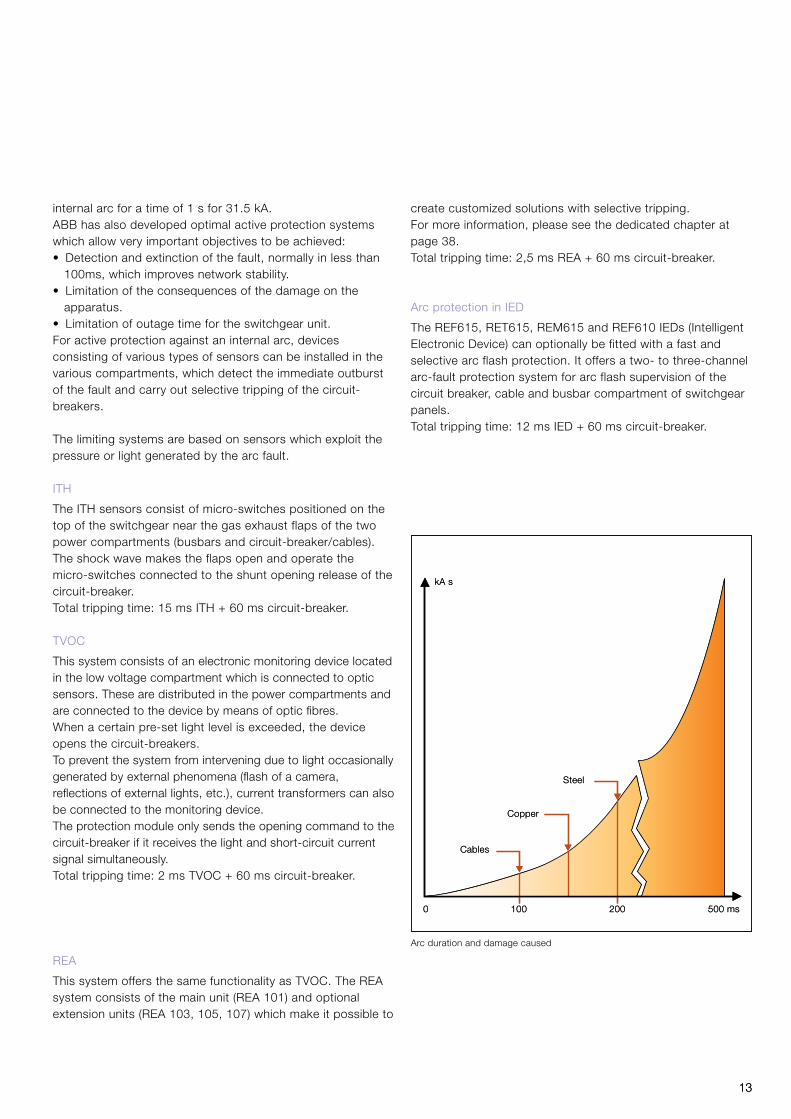
internal arc for a time of 1 s for 31.5 kA.ABB has also developed optimal active protection systemswhich allow very important objectives to be achieved:• Detection and extinction of the fault, normally in less than
100ms, which improves network stability.• Limitation of the consequences of the damage on the
apparatus.• Limitation of outage time for the switchgear unit.For active protection against an internal arc, devices consisting of various types of sensors can be installed in the various compartments, which detect the immediate outburst of the fault and carry out selective tripping of the circuit-breakers.
The limiting systems are based on sensors which exploit the pressure or light generated by the arc fault.
ITH
The ITH sensors consist of micro-switches positioned on thetop of the switchgear near the gas exhaust flaps of the twopower compartments (busbars and circuit-breaker/cables).The shock wave makes the flaps open and operate the micro-switches connected to the shunt opening release of the circuit-breaker.Totaltrippingtime:15msITH+60mscircuit-breaker.
TVOC
This system consists of an electronic monitoring device located in the low voltage compartment which is connected to optic sensors. These are distributed in the power compartments and are connected to the device by means of optic fibres.When a certain pre-set light level is exceeded, the device opens the circuit-breakers. To prevent the system from intervening due to light occasionally generated by external phenomena (flash of a camera, reflections of external lights, etc.), current transformers can also be connected to the monitoring device.The protection module only sends the opening command to the circuit-breaker if it receives the light and short-circuit current signal simultaneously.Totaltrippingtime:2msTVOC+60mscircuit-breaker.
REA
This system offers the same functionality as TVOC. The REA system consists of the main unit (REA 101) and optional extension units (REA 103, 105, 107) which make it possible to
Arc duration and damage caused
create customized solutions with selective tripping.For more information, please see the dedicated chapter at page 38.Totaltrippingtime:2,5msREA+60mscircuit-breaker.
Arc protection in IED
The REF615, RET615, REM615 and REF610 IEDs (Intelligent Electronic Device) can optionally be fitted with a fast and selective arc flash protection. It offers a two- to three-channel arc-fault protection system for arc flash supervision of the circuit breaker, cable and busbar compartment of switchgear panels. Totaltrippingtime:12msIED+60mscircuit-breaker.

14 14
Triple key lock on earthing switch
The UniGear ZS2 switchgear is fitted with all the interlocks and accessories needed to guarantee the highest level of safety and reliability for both installation and personnel.
Interlocks
The safety mechanical interlocks are standard ones [1÷4A].They are set out by the IEC standards and are thereforenecessary to guarantee the correct operation sequence.The presence of ABB safety interlocks guarantees the highest level of reliability, even in the case of an accidental error, and provide an “error-free” system of interlocks.
Keys
The use of key interlocks is very important in realising the interlocking logics between panels of the same switchgear, or of other medium, low and high voltage switchgear. The logics are realised by means of distributors or by ringing the keys.The apparatus truck [6] can be locked in the racked-out position and the relevant lock key can only be removed with the apparatus in this position.The earthing switch closing [7] and opening [8] operations can be locked by means of keys.The latter can only be removed with the earthing switch in an opposed position to the lock to be made. These locks can also be applied to the earthing switch of busbar applications.Thecircuit-breakerracking-in/outoperations[9]andearthingswitch opening/closing [10] can be prevented by means of key locks, which prevent insertion of the relevant operating levers.The key lock can also be applied to the earthing switch of busbar applications. The keys can always be removed.
Padlocks
The circuit-breaker [11] and cables [12] compartment doors can be locked in the closed position by means of padlocks. The operations for apparatus racking-in/out [13] and earthing switch opening/closing [14] can be prevented by applying the padlocks to the insertion slots of the relevant operating levers. The padlock can also be applied to the earthing switch of busbar applications.The metallic segregation shutters [15] between circuit-breaker, busbars and cables compartments can be locked by means
of two independent padlocks in both the open and closed positions.Padlocks from 4 to 8 mm diameter can be accommodated.
Locking magnets
The locking magnets enable automatic interlocking logics without human intervention.The circuit-breaker racking-in/out [16] and the earthing switch ON/OFF [17] operations can be interlocked. This magnet can also be applied to the earthing switch of busbar applications. The magnets operate with active logics and therefore the lack of auxiliary voltage leaves the interlocking system active (in safety condition).
1. UniGear ZS2 Safety

15 15
Standard safety interlocks
Type Description Condition to be fulfilled
1A Apparatus racking-in/out Apparatus in OFF position
B Apparatus closing Defined truck position
2A Apparatus racking-in Apparatus multi-contact plug plugged
B Apparatus multi-contact plug unplugging Truck in test position
3A Earthing switch closing Truck in test position
B Apparatus racking-in Earthing switch in OFF position
4A Apparatus racking-in Apparatus compartment door closed
B Apparatus compartment door opening Truck in test position
5A Feeder compartment door opening Earthing switch in OFF position
B Earthing switch opening Cable compartment door closed
Keys (on request)
6 Apparatus racking-in lock Can only be removed with the truck in the racked-out position
7 Earthing switch closing lock Can only be removed with the earthing switch open
8 Earthing switch opening lock Can only be removed with the earthing closed
9 Insertion of the apparatus raking-in/out crank lever Can always be removed
10 Insertion of the earthing switch operating lever Can always be removed
Padlocks (on request)
11 Apparatus compartment door opening
12 Cable compartment door opening
13 Insertion of the apparatus raking-in/out crank lever
14 Insertion of the earthing switch operating lever
15 Shutters opening or closing
Locking magnets (on request)
16 Apparatus racking-in/out Magnet energized
17 Earthing switch ON/OFF Magnet energized
Standard accessory devices
18 Apparatus-switchgear unit compatibility matrixThe apparatus multi-contact plug and relative switchgear unit socket are equipped with a mechanical matrix, that disables apparatus racking-in into a switchgear unit with an inappropriate rated current.
19 Circuit-breaker mechanical operating mechanism ( Open push button )
The apparatus compartment is equipped with a mechanical device, that enables circuit-breaker copening directly by means of the front operating mechanism pushbutton, keeping the door closed. The controls can be operated with the circuit-breakers in the service and racked-out position.
Optional accessory devices
20 Circuit-breaker mechanical operating mechanism ( Close push button )
The apparatus compartment is equipped with a mechanical device, that enables circuit-breaker closing directly by means of the front operating mechanism pushbuttons, keeping the door closed. The controls can be operated with the circuit-breakers in the service and racked-out position.

16 16
1. UniGear ZS2 Vacuum circuit-breaker
UniGear ZS2 switchgear can be fitted with the widest rangeof apparatus available on the market today, and of these thevacuum circuit-breaker now occupies a position of primeimportance in all sectors of primary distribution.Vacuum circuit-breakers cover the whole range of switchgear parameters and therefore the whole range of applications.In standard version circuit breakes are withsrawable cassete type.
In case of need floor truct type circuit breakers also can be provided as an option.Many years of experience gained in developing and using vacuum interrupters is today reflected in the range ofABB circuit-breakers, which stand out for their exceptionalelectrical and mechanical characteristics, extremely long life,

17 17
low maintenance, compactness and the use of highlyinnovative construction techniques.ABB develops and produces a complete range of interrupters for use in circuit-breakers and contactors and for all medium voltage applications. VD4 circuit-breaker
The VD4 medium voltage circuit-breaker interrupters use the vacuum to extinguish the electric arc and as the insulating medium.Thanks to the unequalled properties of vacuum and the breaking technique used, current interruption takes place without arc chopping and without overvoltages. Restoration of the dielectric properties following interruption is extremely rapid.The VD4 circuit-breakers are used in electrical distribution for control and protection of cables, overhead lines, transformer and distribution substations, motors, transformers, generators and capacitor banks.
Poles
The VD4 medium voltage circuit-breakers use vacuum interrupters embedded in poles ().Embedding the interrupter in the pole makes the circuit-breaker particularly sturdy and protects the interrupter itself against shocks, deposits of dust and humidity. The vacuum interrupter houses the contacts and provides the interruption chamber.
ABB circuit-breakers use the most advanced vacuum breaking techniques: with radial magnetic flow for circuit- breakers with medium-low performance and with axial magnetic flow for those with high breaking capacity. Both techniques guarantee even distribution of the arc roots over the whole surface of the contacts, allowing optimum performance at all current values.The structure of a vacuum interrupter is relatively simple. The housing is made up of a ceramic insulator closed at the ends by stainless steel covers. The contacts are made of pure copper and sintered chrome and are welded to the copper terminals. A metallic bellows allows movement of the moving contact-terminal group, at the same time guaranteeing that the vacuum is maintained in the interrupter.The interrupter components are welded in an environmentunder a very strong vacuum to guarantee a vacuum of lessthan 10 Pa in the interrupter. This means that the interrupter does not any ionisable material. In any case, on detachment of the contacts, an electric arc is generated which only consists of the melted and vaporised material of the contact. A metallic shield is integrated inside the interrupter to capture the metallic vapours given off during interruption, as well as for controlling the electric field. The particular shape of the contacts generates a magnetic field which forces the arc to rotate and to involve a much wider surface than that of a fixed contact arc.Apart from limiting the thermal stress on the contacts, thismakes contact erosion negligible and, above all, allows the interruption process to be controlled even with very high short-
VD4 circuit-breaker
18 18
circuit currents.
The electric arc remains supported by the external energy until the current passes through its natural zero.The ABB vacuum interrupters are zero current interrupters and are free of any re-striking phenomena.The rapid reduction of the current density and fast condensation of the metallic vapours, that happens at the at the instant that the current passes through zero, allow the maximum dielectric strength between the interrupter contacts to be re-established within a few milliseconds. Supervision of the vacuum level is not necessary as the circuit-breaker poles are sealed-for-life pressure systems and do not require any maintenance.
Operating mechanism
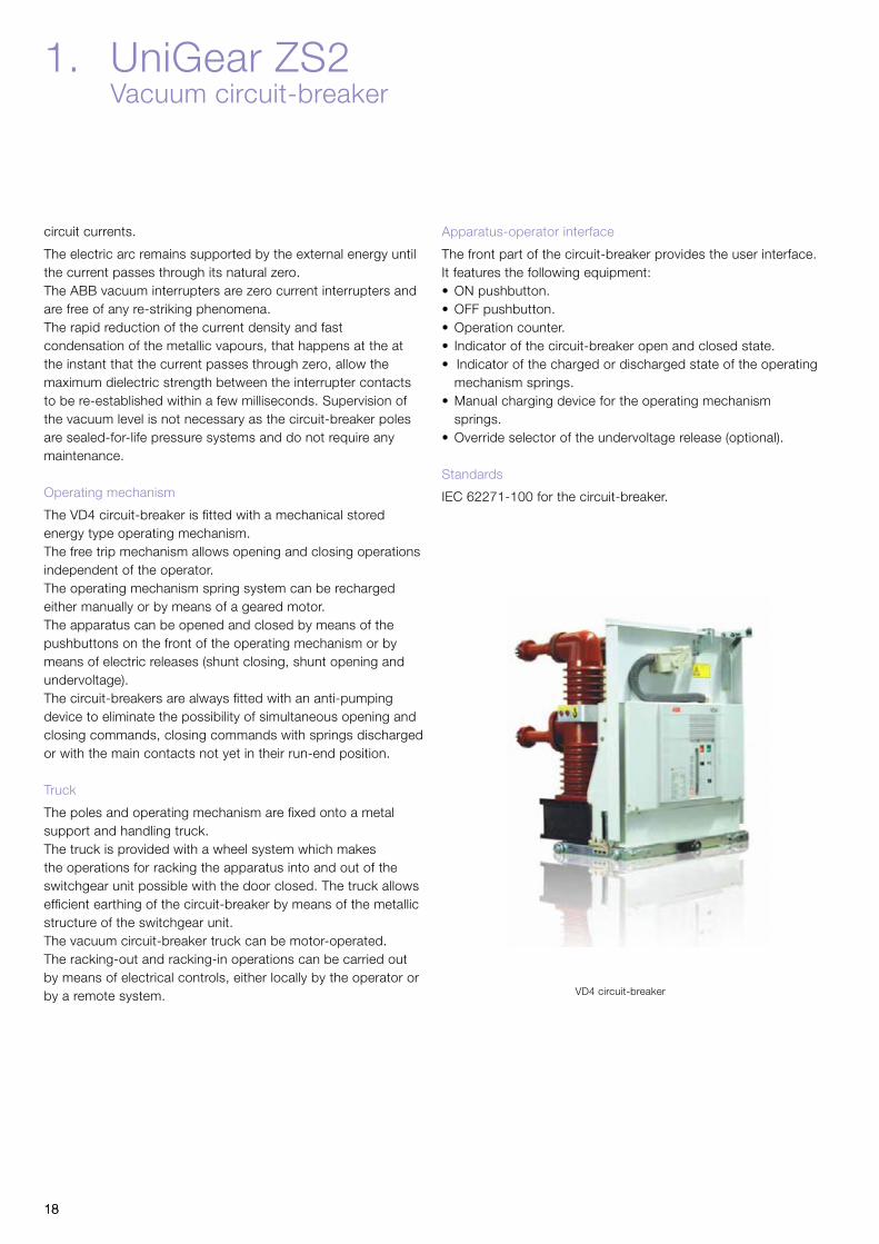
The VD4 circuit-breaker is fitted with a mechanical stored energy type operating mechanism.The free trip mechanism allows opening and closing operations independent of the operator.The operating mechanism spring system can be recharged either manually or by means of a geared motor.The apparatus can be opened and closed by means of the pushbuttons on the front of the operating mechanism or by means of electric releases (shunt closing, shunt opening and undervoltage).The circuit-breakers are always fitted with an anti-pumping device to eliminate the possibility of simultaneous opening and closing commands, closing commands with springs discharged or with the main contacts not yet in their run-end position.
Truck
The poles and operating mechanism are fixed onto a metal support and handling truck.The truck is provided with a wheel system which makes the operations for racking the apparatus into and out of the switchgear unit possible with the door closed. The truck allows efficient earthing of the circuit-breaker by means of the metallic structure of the switchgear unit.The vacuum circuit-breaker truck can be motor-operated.The racking-out and racking-in operations can be carried out by means of electrical controls, either locally by the operator or by a remote system.
Apparatus-operator interface
The front part of the circuit-breaker provides the user interface.It features the following equipment:•ONpushbutton.•OFFpushbutton.•Operationcounter.• Indicatorofthecircuit-breakeropenandclosedstate.•Indicatorofthechargedordischargedstateoftheoperating
mechanism springs.•Manualchargingdevicefortheoperatingmechanism
springs.•Overrideselectoroftheundervoltagerelease(optional).
Standards
IEC 62271-100 for the circuit-breaker.
1. UniGear ZS2 Vacuum circuit-breaker
VD4 circuit-breaker

1919
Interchangeable Vacuum circuit-breaker and SF6 circuit-breaker with UniGear ZS2.
20 20
1. UniGear ZS2 Gas circuit-breaker
HD4 circuit-breaker
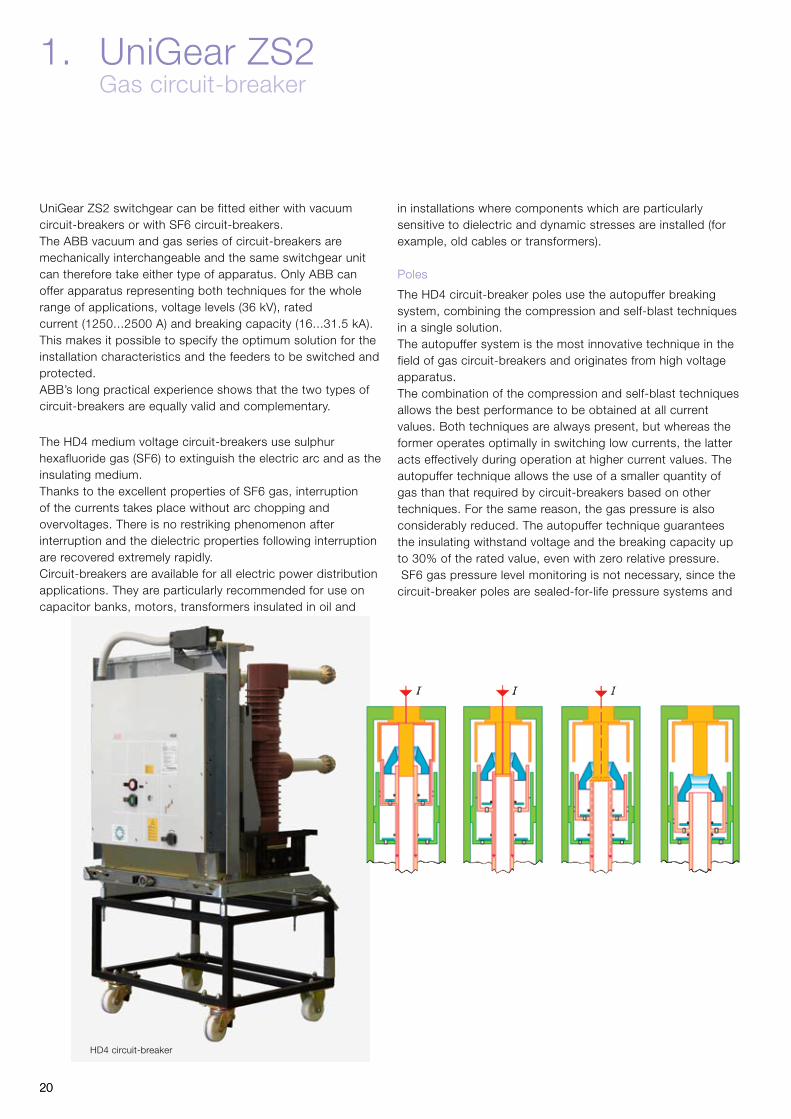
UniGear ZS2 switchgear can be fitted either with vacuumcircuit-breakers or with SF6 circuit-breakers.The ABB vacuum and gas series of circuit-breakers aremechanically interchangeable and the same switchgear unitcan therefore take either type of apparatus. Only ABB canoffer apparatus representing both techniques for the wholerange of applications, voltage levels (36 kV), ratedcurrent (1250...2500 A) and breaking capacity (16...31.5 kA). This makes it possible to specify the optimum solution for the installation characteristics and the feeders to be switched and protected. ABB’s long practical experience shows that the two types of circuit-breakers are equally valid and complementary.
The HD4 medium voltage circuit-breakers use sulphurhexafluoride gas (SF6) to extinguish the electric arc and as the insulating medium.Thanks to the excellent properties of SF6 gas, interruptionof the currents takes place without arc chopping andovervoltages. There is no restriking phenomenon afterinterruption and the dielectric properties following interruption are recovered extremely rapidly.Circuit-breakers are available for all electric power distribution applications. They are particularly recommended for use on capacitor banks, motors, transformers insulated in oil and
in installations where components which are particularly sensitive to dielectric and dynamic stresses are installed (for example, old cables or transformers).
Poles
The HD4 circuit-breaker poles use the autopuffer breakingsystem, combining the compression and self-blast techniques in a single solution.The autopuffer system is the most innovative technique in the field of gas circuit-breakers and originates from high voltage apparatus.The combination of the compression and self-blast techniques allows the best performance to be obtained at all current values. Both techniques are always present, but whereas the former operates optimally in switching low currents, the latter acts effectively during operation at higher current values. The autopuffer technique allows the use of a smaller quantity of gas than that required by circuit-breakers based on other techniques. For the same reason, the gas pressure is also considerably reduced. The autopuffer technique guarantees the insulating withstand voltage and the breaking capacity up to30%oftheratedvalue,evenwithzerorelativepressure. SF6 gas pressure level monitoring is not necessary, since the circuit-breaker poles are sealed-for-life pressure systems and

21 21
are maintenance-free. They are fitted with a pressure control device for checking that the characteristics are not altered due to transport or incorrect operations.
Operating mechanism
The HD4 circuit-breaker is fitted with a mechanical storedenergy operating mechanism. This is free-tripping and therefore allows opening and closing operations independent of the operator.The operating mechanism spring system can be rechargedeither manually or by means of a geared motor. The operating mechanism is of the same type for the whole series and has a standardised range of accessories and spare parts. All the accessory components can easily be replaced by means of plug-socket connectors.Opening and the closing of the apparatus can be carried outby pushbuttons on the front of the operating mechanism or by electric releases (shunt closing, shunt opening and undervoltage).The circuit-breakers are always fitted with an anti-pumpingdevice to eliminate the possibility of simultaneous openingand closing commands, closing commands with springsdischarged or with the main contacts not yet in their run-endposition.
Truck
The poles and operating mechanism are fixed onto a metal support and handling truck.The truck is provided with a wheel system which makes the operations for racking the apparatus out of and into the switchgear unit possible with the door closed. The truck allows effective earthing of the circuit-breaker by means of the metallic structure of the switchgear unit.
Apparatus-operator interface
The front panel of the circuit-breaker provides the user interface. It features the following equipment:•ON pushbutton.•OFF pushbutton.•Operation counter.• Indicator of the circuit-breaker open and closed state.• Indicator of the charged and discharged state of the
operating mechanism springs.•Manual charging device for the operating mechanism
springs.•Override selector of the undervoltage release (optional).•LED gas pressure indicator (optional).
Standards
IEC 62271-100 for the circuit-breaker.IEC 60376 for the SF6 gas.
HD4 circuit-breaker

22 22
1. UniGear ZS2 Service trucks
The UniGear ZS2 range is equipped with all the service trucks needed to complete the switchgear and required for service and maintenance operations.The trucks are divided into five different types:•Earthing without making capacity.•Powercable test.• Isolation without making capacity.•Fused without making capacity.
•Shutter test.
Earthing truck without making capacity
These trucks carry out the same function as the earthing switches without making capacity.They therefore have no capacity to earth live circuits in fault conditions.They are used to ensure an additional fixed earth, as is required by some installation service and maintenance procedures, as a further safety guarantee for personnel.The use of these trucks anticipates removal of the apparatusfrom the switchgear (circuit-breaker) and its replacement with the truck.This truck is available in two versions:•Earthingofthemainbusbarsystem.•Earthingofthepowercables.
The earthing truck of the main busbars, during the racking-in phase, only lifts the top shutter and earths the contacts connected to the top branch connections (and therefore to the main busbar system) by means of the switchgear structure.The earthing truck of the power cables, during the racking-in phase, only activates the bottom shutter and earths the contacts connected to the bottom branch connections (and therefore to the power cables) by means of
the switchgear structure. These trucks can also be used in the bus-tie unit. In this case, they earth one of the two sides of the main busbar system.
Power cable test truck
These trucks allow the insulation tests on the power cables to be carried out without accessing the feeder compartment or disconnecting the cables from the switchgear.The use of these trucks anticipates removal of the apparatus from the switchgear (circuit-breaker) and its replacement with the truck.The truck, during the racking-in phase, only activates the bottom shutter and, by means of the connectors it is fitted with, allows connection of the test apparatus cables.This truck can only be used in the incoming/outgoing feeders with the door open.
Isolating truck without making capacity
The isolating truck allows the top switchgear contacts to be connected directly to the bottom ones. Connection is made safe by using the poles to insulate the connection busbars from the external environment. In the incoming/outgoing feeder units it connects the main busbar system to the power cables, whereas in the bus-tie, to the two sides of the busbar system.This truck has its application in UniGear ZS2 switchgear for making incoming/outgoing feeders without a circuit-breaker in radial networks, for making cable connections between two items of switchgear placed in front of each other, in making interconnection units and in creating the bus-tie riser configuration with double insulation (in this case, both the units are made up of bus-ties, the former fitted with a circuit-breaker and the latter with an isolating truck).
Busbar earthing truck without making capacity Fused truck without making capacity

23 23
Fused truck.
Fused truck without making capacity
The fused truck can be used to protect small power transformers up to 50 kVA with 4 A fuses. It is developed to provide cost effective and technically best possible solution for small transformers. It is developed and tested according to IEC 62271 with M0 class. Fuse breaking capacity of apparatus is 40 kA.The fused truck needs to be electrically interlocked with incoming circuit breaker and downstream LV circuit breaker to protect racking in/out while the down stream circuit breaker is on and busbar is dead.
Shutter test truck
These truck allow the shutter tests on the shutter to be carried out without accessing the feeder compartment.The use of these trucks anticipates removal of the apparatus from the switchgear (circuit-breaker) and its replacement with the truck. The truck, during the racking-in phase, activates the upper and bottom shutter.This truck can be used in the incoming/outgoing feeders with the door closed.
Main busbar system earthingtruck, without making capacity.
Power cable earthing truck,without making capacity.
Cable test truck.
Isolating truck.
Fused Switch (Circuit Breaker) feeder
Fused switch (circuit breaker feeder) can be used with fuses up to 200A to protect transformers and lines. This solution gives LSC2B solution for transformers protection also with a fuse blown indication.Vacuum or SF6 circuit breaker is used to switch the line also to trip the feeder with fuse blown contact.This solution is available only with 1200 mm width cubicle.
Shutter test truck
Fused Switch (Circuit Breaker ) feeder

24 24
1. UniGear ZS2 Instrument transformers
Block type current transformers
The block type current transformers are epoxy resin insulated and used to supply the measurement devices and protection instruments. These transformers can have a wound core or a bushing bar with one or more cores, with performance and accuracy classes suitable for the installation requirements.They conform to the IEC 60044-1 Standards.Their dimensions are in accordance with the DIN 42600Narrow Type Standard, in the Medium and Long Size versions up to 3150 A,The current transformers can also be provided with acapacitive socket for connection to voltage signalling devices.The current transformers are normally fitted on the loadside of the apparatus compartment for measurement of thephase currents of the switchgear unit. Fitting on the supplyside of the apparatus compartment is also possible (busbarapplications) for measuring the busbar currents or for realising particular protection schemes.
Ring core current transformers
The toroidal transformers are of the epoxy resin insulated type and are used to supply measurement and protection devices.These transformers can feature either a closed or openablecore. They can be used both for measuring phase currents or for detecting the earth fault current.They conform with the IEC 60044-1 Standards.
1250 A
2500 A
Toroidal current transformer

25 25
Voltage transformers
The voltage transformers are of the epoxy resin insulated type and are used to supply measurement and protection devices.They are available for fixed assembly or for installation onremovable and withdrawable trucks.They conform with the IEC 60044-2 Standards.Their dimensions are in accordance with the DIN 42600Narrow type Standard.These transformers can have one or two poles, withperformance and precision classes suited to the functionalrequirements of the instruments connected to them.
When they are installed on removable or withdrawable trucks they are fitted with medium voltage protection fuses.
The withdrawable trucks also allow replacement of the fuseswith the switchgear in service. Truck racking-out with thedoor closed automatically operates closure of a metallicsegregation shutter between the live parts of the switchgearand the instrument compartment.
Fixed voltage transformers can be installed directly on themain busbar system (busbar applications).
Withdrawable type voltage transformers can be installed in to the cable compartments of incoming/outgoing feeders for power cable side voltage measuring.
Single pole VTs
Double-pole VTs Single-pole VTs with fuse -

26
Uout
Up
26
Uout
Up
1. UniGear ZS2 Measurement sensors
Sensors–Electronicinstrumenttransformers
An alternative solution for measuring currents is an electronic instrument transformer, called a “sensor” for short. This product can replace conventional instrument transformers of both block and ring core types.The characteristic feature of ABB sensors is the level ofoutput signal, which is analogue voltage signal. The output signal level depends on the principle used and can be:• In the range of mV for current sensor (typical value is 150
mV at rated 80 A primary current)
The UniGear ZS2 can be fitted with 2 sensor types:• KECA250B1–ringtypecurrentsensor.• KECAA–ringtypecurrentsensor.
Characteristics of the sensors
•Linearresponseoverthewholemeasurementfield.•Excellentfrequencyresponse.•Nohysteresisphenomenon.•Highdegreeofimmunitytoelectromagneticdisturbance.•Asingleinstrumentforprotectionandmeasurement
devices.•Cl.1overallclassofmeasurement(sensorsandmulti
purpose unit).•Anyshort-circuitsorinterruptionsofthesecondarycircuit
do not cause any damage.•Theoutputsignalremainsveryloweveninprimaryfault
situations.•Testterminalblocksarenotrequired.•Connectionbetweenthesensorandthemeasurementand
protection instrument is made with shielded cables and connectors.
Benefits provided by the sensors
• Improvementofselectivity.•Moreefficientfaultlocation.•Perfectingoffaultanalysis.•Simplificationofengineeringtasks.
KECA ring core type sensor
•Morerapidandlesscostlyswitchgearmodificationsandupgrading.
•Simpleandsafetestmaintenanceoperations.•Reductioninfaultsinthemeasurementandprotection
apparatus.•Safetyforoperatorsduetoeliminationofaccidental
opening of secondary CT’s circuits.•Optimisationofmaintenanceprogrammes.•Reductioninthenumberofspareparts.• Lowerlifecyclecost.
Current sensor
The current sensor consists of a Rogowski coil without the ferromagnetic core.The coil is formed by a uniform winding over a closed non-magnetic core of constant cross section. The induced voltage in the secondary circuit is directly proportional to the variation in the let-through current. The multi-purpose device integrates the signal to obtain the current value.They conform to the IEC 60044-8 Standards.
Rogowski coil
Uout = M dip
dt
Characteristics of the current sensors
•Nosaturationphenomenon.•Precisemeasurementofthefaultcurrents.•Thesensorwindingcanremainopenevenwiththe
switchgear in service.•Justtwocoilscovertherangefrom0to2500A.
The output signal (Uout) is a voltage (150 mV at 50Hz and 180mV at 60Hz) proportional to the variation in the current time (Ip); the current measurement is obtained by integrating the signal.

27
Circuit breaker with trolley
27
Busbar compartment
Circuit breaker compartment with shutters Cable compartment with current transformers

28 28
1. UniGear ZS2 Distribution automation
ABB protection philosophy
Having delivered protection IEDs to more than 70 countries, ABB fully understands the need for diverse protection philosophies that meet local legislation, safety requirements and engineering practice.The main purpose of an IED protection system is to recognize any abnormal power system condition, or abnormally operating system component. Based on the information gathered, the protection system will initiate corrective actions that return the system to its normal operating state.IED protection does not prevent network faults from arising, but it is activated only when something abnormal has occurred in the power system. However, careful selection ofprotection functions and methods improves the performanceand the reliability of the protection system, thus minimizingthe effects of network faults and preventing the disturbancefrom spreading to the healthy parts of the network.
Advantages of a complete protection system
Operating speed, sensitivity, selectivity and reliability of the protection system need close attention. There is a strong correlation between the operating speed of the protection system and the damage and danger caused by a network fault. Substation automation provides remote control and monitoring capabilities, which speed up the location of faults and the restoration of the power supply.Fast operation of the protection IEDs also minimizes post-fault load peaks, which together with voltage dips increase the risk of the disturbance spreading to healthy parts of the network. The sensitivity of the protection must be adequate to detect relatively high resistance earth faults and short-circuits in the most distant parts of the network. Reliable selectivity is essential in order to limit the loss of power

29
High requirement
Feed
er t
ype
IED
Fea
ture
s
Standard requirement
Infeed from both ends
Ring main feeders
Parallel feeders
Feeders with distributed genera-tion
Radial feeders with reclosers/sectionalizers
Radial feeders
Distance protection
Single line diagram HMI*
Fault locator
Power quality monitoring
Communication
Auto re-closure
Single function* Human Machine Interface
Comparison between standard and high requirement feeders
supply to as small an area as possible, and to allow the faulted part of the network to be reliably identified. Corrective actions can then be directed to the faulty part of the network, so that the supply can be restored as rapidly as possible.The protection system must have a high degree of reliability.This also means that if, for example, the CB fails to operate, the back up protection will clear the fault.Substation automation (SA) puts the operator in perfectcontrol of the substation. In addition, the SA system improves the power quality of the transmission and distribution networkunder normal operation, but especially in a situation ofdisturbance and during substation maintenance. An SA system or SCADA brings the full benefits of digital technology into protection and control of networks. The terminals are easily setup and parameterized through easy and safe ccess via the operator’s workplace.Single-function and multi-function terminals
Correct protection methods and comprehensive functionality
increase the performance of the protection system. The definition of comprehensive functionality varies with the requirements of the protected network. While single-function protection IEDs are sufficient for some network applications,more complex networks need advanced multi-functional IEDs.Single-function IEDs include a set of protection functions fora specific feeder application type. The main advantages ofthese IEDs are redundancy and price. One or more single-function IEDs provide sufficient protection in most application areas.Multi-function terminals include a large number of protectionfunctions that meet the needs of a wide range of applications. In addition, they include control, measurement, power qualitymonitoring and condition monitoring functions. The use of one single IED incorporating all these functions increases system usability, reduces costs and minimises the need for wiring in the switchgear.

30
Feeder protection
The protection applications can be roughly divided into two categories, namely standard applications utilizing basic current based protection and high requirement applications utilizing current and voltage based protection and their combinations (see table on next page).The selected protection scheme has to fulfill the application specific requirements regarding sensitivity, selectivity and operating speed. The protection requirements are mainly determined by the physical structure of the network. In most cases the above requirements can be fulfilled with non-directional/directional overcurrent IEDs. In networks with a more complex structure more advanced protection functions like distance protection or line differential protection may have to be introduced.The purpose of the over- and under-voltage protection system is to monitor the voltage level of the network. If the voltage level deviates from the target value by more than the permitted margin for a specific time period, the voltage protection system limits the duration of the abnormal condition and the stresses caused.
To prevent major outages due to frequency disturbances, the substations are usually equipped with underfrequency protection IEDs, which in turn control various load-shedding schemes.These are just a few examples of the major protection fun-ctions for feeders. More details can be found in the technical documentation produced for the ABB protection and control devices.
Applications and features
Depending on the requirements a suitable IED type can be selected and configured in such a way that an overall solution can be found for different feeder types.Generally, the required protection functionality of the above feeder types differs very much from each other depending on, for instance, the characteristics of the fault current sources and the types of more advanced functions that may be needed to fulfill the basic requirements of the protection application. In the following a few examples are given toillustrate the requirement level.
1. UniGear ZS2 Distribution automation
Typical standard feeder

31
Recommended products
ABB supplies a wide range of feeder protection and control devices and terminals to fulfill the requirements of each discrete application. For an application with standard requirements and a basic need for additional features, theREF615andREX521unitsareexcellentchoices.Forapplications with higher functionality requirements, the multifunction terminals REF 54_ should be selected. Especially for applications requiring absolutely selective feeder protection (unit type of protection), the line differential IED RED615 can be applied. This IED maintains selectivity even in cases where the fault current magnitude varies and fault current can be fed from several sources. This is usually the case in closed loop, ring type and meshed networks.
Typical high requirement feeder

32
Transformer protection
The power transformer is an important component and one of the most valuable discrete units in the power distribution network. A high availability of the power transformer is therefore of particular importance for preventing disturbances in the power distribution system.Although high-quality power transformers are highly reliable, insulation breakdown faults sometimes occur. These faults appearing as short circuits and/or earth faults generally cause severe damage to the windings and transformer core. The damage is proportional to the fault clearing time so the power transformer must be disconnected as quickly as possible. The power transformer has to be transported to a workshop for repair, which is a very time-consuming process. The operation of a power network where the power transformer is out of service is always cumbersome. Therefore, a power transformer fault often constitutes a more severe power system fault than a line fault, which usually can be rectified rather quickly. It is extremely important that fast and reliable protection IEDs are used to detect transformer faults and initiate tripping.The size, voltage level and importance of the power transformer determine the extent and choice of monitoring and protection devices to be used to limit the damage at a possible fault. When compared to the total cost of the power transformer and the costs caused by a power transformer fault, the cost of the protection system is negligible.
Applications and features
ABB divides transformer protection applications into standard transformer protection application and high requirement transformer applications.
The core functionality levels are as below:
•Standardrequirement–Suddenpressure(Buchholz)-IED
•Differentialprotection
•Overcurrentprotection
•Earthfaultprotection
•Overloadprotection
•Unbalanceprotection
•Oillevelmonitor
High requirement functionality levels are:
•Suddenpressure(Buchholz)-IED
•Differentialprotection
•Overcurrentprotection
•Restrictedearthfault(REF)protection
•Overloadprotection
32
1. UniGear ZS2 Distribution automation
Typical standard transformer protection

33
•Unbalanceprotection
•Over/Under-voltageprotection
•Over/under-frequencyprotection
•Oil-levelmonitor
Recommended products
The RET 541/543/545 Transformer Terminals are designed for comprehensive protection, control, measurement and supervision of two-winding power transformers and power generator-transformer blocks in the power distribution networks of utilities and industrial plants. It is also suitable for application where on-load tap-changer control is requiredFunctionality for standard transformer protection is provided in the REF 542plus terminal.
33
Typical high requirement transformer protection

34 34
Motor protection
Motor protection is generally expected to provide overcurrent, unbalance, earth-fault and short-circuit protection. However, the fundamental issue for motors is thermal protection, as overheating is the worst threat for the motor.Motors need to be protected not only against electrical faults but also against any improper way of running them. ABB’s solutions focus on advanced thermal protection that prevents improper use of the motors. The thermal overload protection is needed to protect the motor against both short-time and long-time overload and so it is of great importance for the performance of the motor. Overload conditions of short duration mainly occur during motor start-up.There are four crucial elements in thermal motor protection. •Thethermaloverloadprotectionisthemostimportant
protection function of the motor as it monitors the thermal load and memorizes the related events.
•Acumulativestart-uptimecountersupportingtheoverloadprotection limits the number of consecutive cold starts.
Typical standard motor protection
•Thethermalstressduringanysinglestart-upconditionis monitored by the start-up supervision function, which protects the motor against locked rotor situations and over long start-up times.
•Thefourthelementinthermalmotorprotectionisthermalprotection based on RTD (Resistance Temperature Detector) sensors. As RTD sensors directly measure the temperature of the stator winding, bearings, etc., this type of thermal protection is especially useful if the motor’s cooling system is blocked.
Improper use of running motors does not necessarily damage the equipment but shortens its lifetime. Therefore, a reliable and versatile motor protection system not only protects the motor but it also prolongs its life-cycle, which contributes to improving the return on investment of your motor drive.
Applications and features
Thanks to comprehensive communication protocols, including
1. UniGear ZS2 Distribution automation

35 35
Typical high requirement motor protection
the widely used industrial protocols such as Modbus RTU/ASCII and Profibus DP, ABB motor protection IEDs and terminals can be easily integrated into various control systems.
Recommended products
The REM 610 is designed for the protection of standard medium and large MV asynchronous motors in a wide range of motor applications. The typical size of protected motors ranges from 500 kW to 2 MW.TheREX521andREF542plusaresuitablewhenthereisaneed to have control functionality in addition to the motor protection.The REM 543/545 machine protection terminals provide high-end protection, including differential protection, for all sizes of asynchronous or synchronous motors.

36 36
1. UniGear ZS2 Distribution automation
Station Automation COM600 Series
The Station Automation COM600 Series is a dedicated system for providing inter-operability between industrial or utility substation IEDs (Intelligent Electronic Devices) and local or higher-level systems, such as local operator interfaces or higher-level Network Control Centers (NCC) or Distributed Control Systems (DCS). The series features gateway functi-onality supporting a variety of commonly used substation device communication protocols.
Products
The Station Automation COM600 Series offers web server functionality, providing a human machine interface (HMI) for local substation monitoring and control. Secure communication enables access to the substation HMI over the internet or LAN/WAN for any authorized user with a standard PC and a web browser. By connecting a laptop computer to the unit locally, an HMI for full monitoring and control functionality is obtained at the substation level. The Station Automation COM600 Series also provides gateway functions for mapping data and signals between substation and higher-level systems such as SCADA, DSC. The entire COM600 series is designed for smooth system integration and interoperability based on pre-configured solutions utilizing connectivity packages for ABB IEDs.
Advantages
Open access to real-time information.The COM600 series products incorporate OPC Server functionality, which provides one entry point to all the substation information, and the IEC 61850 support enables connectivity and seamless communication with application-specific equipment.
Full IEC 61850 compliance
The COM600 series products are fully compliant with the IEC 61850 standard for distribution automation. This means that they provide full interoperability with any IEC 61850 compliant IEDs, tools and systems, which simplifies system design and commissioning.
Fast commissioning of ABB IEDs
The commissioning of ABB IEDs is straight forward due to the support of ABB’s unique connectivity package concept, which simplifies system configuration and reduces the risk of errors in the system integration, minimizing device configuration and set-up times.
Application and features
With their compact and robust design, the COM600 series products are well adapted for harsh environments. They meet the IP4x degree of protection by enclosure and contain no moving parts subject to wear and tear. The COM600 series products are based on embedded technology for durability and maximum availability.The features and compact dimensions of the COM600 series products enable them to be easily installed in the low voltage compartment of UniGear ZS2 panels. COM600 series products are suitable for both industrial and utility applications.

37 37
Industrial Application
Utility Application

38
1. UniGear ZS2 Distribution automation
38
1. UniGear ZS2 Distribution automation
Arc protection
An electric arc short-circuit in a switchgear installation is normally caused by a foreign object entering the cubicle or a component failure. The arc causes an explosion-like heat and pressure effect, usually causing vast damage to the switchgear and injury to personnel.An adequate arc protection system protects your substation against arc faults by minimizing the burning time of the arc,thus preventing excessive heat and damage. It minimizesmaterial damage and allows power distribution to be smoothly and safely restored. The system can also bring cost benefits even before an arc fault occurs. As older switchgear is more prone to arc faults, an arc protection system will effectively extend the life of your switchgear enhancing the return on your investment. But what is even more important, this technology can help save lives.
Applications and features
Sources of arcing may be insulation faults, mal-operating devices, defective bus or cable joints, over-voltage, corrosion, pollution, moisture, ferro-resonance (instrument transformers) and even ageing due to electrical stress. Most of these arc fault sources could be prevented by sufficient maintenance.However, in spite of the precautions taken, human errors can lead to arc faults.Time is critical when it comes to detecting and minimizingthe effects of an electric arc. An arc fault lasting 500 ms may cause severe damage to the installation. If the burning time of the arc is less than 100 ms the damage is often smaller, but if the arc is extinguished in less than 35 ms its effect is almos unnoticeable.Generally applied protection IEDs are not fast enough toensure safe fault clearance times at arc faults. The operation
time of the over-current IED controlling the incoming CB may, for instance, have been delayed to hundreds of milliseconds for selectivity reasons. This delay can be avoided by installing an arc protection system. The total fault clearance time can be reduced to a maximum of 2.5 ms plus the circuit breaker’s contact travel time.Furthermore, at cable compartment faults, auto-reclosurescan be eliminated by employing arc protection.
Recommended products
The arc protection system REA 101 with its extension units REA 103, REA 105 and REA 107 is designed to be used for the protection of medium and low-voltage air-insulated switchgear. The central unit type REA 101 operates independently or together with other REA 101 units. REA is the fastest arc protection system on the market, providing tripping times down to 2.5 ms. REA is equipped with a fast integrated overcurrent-sensing element and it therefore works independently from other feeder protection units. The REF615 feeder protection IED includes an optional arc protection function for the feeder cubicle. Enhanced with an optional plug-in card, the IED offers a three-channel arc-fault protection system for supervision of the switchgear CB, cable and busbar compartment. It provides tripping times down to 10-12 ms. This fast arc-fault protection increases personnel safety, reduces material damages within the switchgear and minimizes system down-time.For a high level of switchgear arc protection we recommend a combination of REF615 and REA arc protection.
Fig. 10 Typical setup with REA 101 and subunits 103

39
REF 615 REX521 REF 54_ RET 54_ REM 54_ REM 610 REA 10_ RED 615
Application
Feeder application • •
High requirement feeder application • •
Transformer application • •
High requirement transformer application •
Motor protection (•) (•) • •
High requirement motor application •
Generator & synchronous motor •
Distance protection •
Line differential protection •
Arc protection for feeder cubicle • • •
Arc protection system •
Communication protocols
IEC 61850-8-1 • •* •* •* •* •* •
IEC 60870-5-103 • • • •
DNP 3.0 • •
SPA • • • • •
LON • • • • •*
Modbus • • • • • •
Profibus •* •* •* •* •*
Additional functionally
Fault locator •
CAN interface •
On load tap changer control •
Disturbance recording • • • • • • •
Withdrawable release mechanics • • •
Condition monitoring • • • • • •
Single line diagram HMI ** • • • •
Local control • • • • •
Remote control • • • • • •
Power quality monitoring • •
Sensor inputs • • • • •
Auto re-closure 5 shots 5 shots 5 shots 5 shots
RTD *** inputs 8 8 8 8 6
* With interface adapter** HMI - Human Machine Interface*** RTD - Resistive Temperature Detector
39
* With interface adapter** HMI - Human Machine Interface*** RTD - Resistive Temperature Detector
Selection table
“For more information on Distribution Automation please visit www.abb.com/substationautomation”.

40 40
1. UniGear ZS2 Automatic transfer systems
Single-line diagram of UniGear ZS2 switchgear with REF542plus architecture applied, suitable for carrying out automatic and manual transfer (ATS), as well as the switchgear protections and measurements
Automatic transfer systems are used to ensure maximum service continuity, supplying the power users uninterruptedly.All this is possible using various systems based on different kinds of techniques.The most common of these are outlined below, with the relevant average transfer times:•Delayed: 1500ms•Dependingontheresidualvoltage: 400-1200ms•Synchronised(ATS): 200-500ms•Highspeed(HSTS): 30-120ms
The first two systems are the simplest and can also be achieved with conventional logics and instruments. They guarantee average transfer times and can therefore be used in installations where voltage gaps are not particularly critical.Ontheotherhand,theothertwosystems(ATS–AutomaticTransferSystemandHSTS–HighSpeedTransferSystem)require microprocessor-based apparatus with high technology content.They guarantee fast transfer times and their application is in plants where the process is particularly critical, so that transfers which are not extremely fast would cause serious malfunctions or interruption of the process itself.ABB is able to offer all the transfer systems, from the simplest to the most complex.ATS
The REF542plus unit can be used in medium voltage
switchgear to manage automatic and manual transfer between two different incoming feeders.The time needed for automatic transfer carried out by means of the REF542plus unit is between 200 and 300 milliseconds (including the circuit-breaker operating times). This time can vary within the range indicated in relation to the complexity of the software transfer logics.Switchgear equipped with REF542plus, suitably programmed, are complete and efficient systems able to manage transfer between one power supply system and an alternative one, or to reconfigure the network, passing from double radial distribution to a simple system, in a fully automatic way.It is also possible to carry out the same operation manually from a remote control station, or from the front of the switchgear under user supervision.Manual transfer means making the passage parallel: by means of the synchronism control function (synchro-check –code25)implementedfromtheREF542plus,thepowersupply lines are closed simultaneously with synchronisation of the voltage vectors to then return to being disconnected when transfer has taken place. The applications described do not require additional instruments.
HSTS (High speed transfer device) - SUE 3000
Voltage decreases or complete supply interruptions represent the most important and critical problems for the quality of

41 41
energy supply today. The SUE 3000 High Speed Transfer Device guarantees an optimum safeguarding of energy supply. The device ensures the continued supply to the consumer through automatic transferring to a stand-by feeder and protects the subsidiary process from expensive stoppage time. Furthermore, through the possibility of manually-initiatedtransfers–fortargeted–clearings,forexample–theoperation of the installation is considerably simplified.
Application areas
The SUE 3000 High Speed Transfer Device can be implemented everywhere where a disturbance of the electrical supply would lead to a breakdown in production, which would impact on operating costs. Possible areas of utilization include for example:1. Auxiliary installation serving power stations2. Environmental technology installations3. Voltage supply to continuous industrial processes.
In order to realize a permanent availability, the load is supplied from at least two synchronized feeders which are independent from one another and which are equipped with High Speed Transfer Devices.
HSTS system in the configuration with three circuit-breakers with bus-tie: when the lack of voltage in one of the two power supply units is detected, the closing command of the bus-tie and the opening command for the switchgear unit without voltage are launched simultaneously.
The High Speed Transfer Device takes on the task of ensuring uninterrupted continuous operation of the connected devices in case of a power supply breakdown, taking into account different physical factors, through the most rapid possible transfer to a different feeder kept on standby.
Corresponding to its multi-faceted areas of application, theSUE 3000 is set up for different switchgear arrangements.
Permanent network comparisons
An exceptionally important characteristic, that clearly distinguishes the High Speed Transfer Device SUE 3000 from competing concepts, is that synchronicity criteria are continuously available, e.g. that they are computed online by the SUE 3000. For this reason, in case of an initiation, the appropriate transfer mode is already determined and can be immediately initiated. This means that the probability of a fast transfer is considerably enhanced. Systems which wait for the instant of initiation to start the determination of the network status are not capable, considering the physical parameters, to perform a fast transfer with minimum interruption time. Transfer modes and times
Four different transfer modes are available in detail: Fast transfer, Transfer at the 1st phase coincidence, Residual voltage transfer, Time-operated transfer. The fast transfer is the optimum transfer mode for ensuring in case of fault that only a minimum interruption of the voltage supply occurs. In case of fast transfer the total transfer time, counting from a fault in the main feeder until the standby feeder is cut in, is less than 100ms.
An example of switchgear configuration SUE 3000 High Speed Transfer Device

42
With
dra
wab
le
With
dra
wab
le
With
dra
wab
le
With
dra
wab
le
With
dra
wab
le
42
With
dra
wab
le
With
dra
wab
le
With
dra
wab
le
1. UniGear ZS2 Typical units and technical data
M - Measurements IFD - Direct incoming/outgoing feeder IFDM - Direct incoming/ outgoing feeder with measurements
IF - Incoming/outgoing feeder RM - Riser with measurementsBT - Bus-tie R - Riser
Key to components
Standard components Accessories Alternative solutions
Single-line diagram of typical units
Earthing switch postion will be between circuit breaker and current transformers for units up to 31.5 kA 1 sec due to usage of ST US 36.
For 31.5 kA 3 sec EK6 type earthing switch will be used on cable side of units as shown in above illustrations.
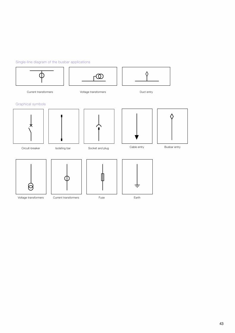
43 43
Single-line diagram of the busbar applications
Duct entry Current transformers Voltage transformers
Graphical symbols
Circuit-breaker Socket and plugIsolating bar
Fuse Voltage transformers Current transformers
Busbar entry
Earth
Cable entry

44 44
1. UniGear ZS2 Typical units and technical data
... 36 kV - ... 31.5 kA
Depth (mm) 2400 2600
Height (mm) 2310 2310
Height with gas exhaust duct (mm) 2662 2662
Width (mm) 1000 1200
Rated current (A) 1250 1600 2000 2500* 1250 1600 2000 2500* 3150*
IF Incoming/outgoing
with Fixed Voltage Transformers
with Fixed fused Voltage Transformers
with Withdrawable fused Voltage Transformers
Fused Switch (Circuit Breaker Feeder)
BT Bus-tie
R Riser
RM Riser with measurements
M Measurements
IFD Direct incoming/outgoing
IFDM Direct incoming/outgoing with measurement ( with Withdrawable fused Voltage Transformers )
Connections
Connection suitable for power cables up to 2x400mm2 per phase**
Connection suitable for power cables up to 4x630mm2 per phase**
Top busbar connection Please consult ABB for details
Top cable entry Please consult ABB for details
* Available with forced cooling fans
** In case of surge arrestor usage,connectable cable per phase should be reduced 1 for each.
In case of remowable VT usage, connectable cable per phase should be reduced 1 for each.
Colored cells indicates availability

45 45
Unit compartments1 Circuit breaker compartment2 Busbar compartment3 Cable compartment4 Low voltage compartment5 Optional Arc channel 6 Current transformers7 Voltage transformers8 Earthing switch
The completed assembly of arc vent duct for middle panel with flap channel (total height of the switchgear is 2662 mm)

46 46
Most switchgear used in installations with normal service conditions is based on single busbar systems.When compared with double busbar switchgear, single busbar switchgear is definitely easier to operate and maintain, requires less space and the total cost of the installation is lower (equipment, site procedures, maintenance, footprint etc.).The use of double busbar switchgear may be necessary when some of the following features are required:–Operationofincomingfeederswithnon-synchronised
circuit-breakers.–Loadsheddingofoutgoingfeederswithadifferentlevelof
importance during emergency conditions.–Isolationofparticularoutgoingfeedersfromthenormal
network.–Outgoingfeedersbalancingontwobusbarsystemsduring
normal service.–Flexibilityduringinspectionandmaintenanceprocedures
without load interruption.–Extensionwithoutswitchgearshutdown.The double busbar system is based on the following scheme:–Twobusbarsystems,twocircuit-breakerscompartments
with one or two circuit breakers (duplex system).
This scheme provide full busbar system redundancy (physical isolation between source busbar systems) and allow uninterrupted and reliable service conditions.
This solution has two main advantages :
–Incomingfeedersandthemostimportantoutgoingfeederscan be equipped with two circuit-breakers in order to allow apparatus redundancy .
–Circuit-breakermaintenanceandtestingwithoutfeedershutdown.
–Fewernumberofcomponentsandlessswitchingapparatus.Thanks to the numerous standard units available, the switchgear can be suitably configured to satisfy all installation
Single Busbar Section
2. UniGear ZS2 Double Busbar System Description
Earthing switch postion will be between circuit breaker and current transformers for units up to 31.5 kA 1 sec due to usage of ST US 36.
For 31.5 kA 3 sec EK6 type earthing switch will be used on cable side of units as shown in above illustrations.

47 47
requirements.Each unit can be equipped with circuit-breakers or fused disonnectors, as well as with all the accessories available for conventional switchgear units.All the significant components are identical to those used for the single level units and therefore the same service and maintenance procedures are guaranteed.The units can be arranged as required by the installation requirements, but, according to the technical literature, the switchgear must be configurable as per the following two schemes:–Singlebusbarsection.–Doublebusbarsection.
Double Busbar Section
IEC electrical characteristics
Rated voltage [kV] 36
Test voltage (50-60 Hz/1min [kV] 70
Impulse withstand voltage [kV] 170
Rated frequency [Hz] 50-60
Rated short-time withstand current [kV 3 s] up to 31.5
Peak withstand current [kA] up to 80
Internal arc withstand current [kV 1 s] up to 31.5
Rated current of the main busbars [A] up to 3150
Rated circuit-breaker thermal current * [A] up to 3150
Double busbar feeders rated current* [A] 3150
*2500A and 3150A ratings are available only with forced cooling fans.
Earthing switch postion will be between circuit breaker and current transformers for units up to 31.5 kA 1 sec due to usage of ST US 36.
For 31.5 kA 3 sec EK6 type earthing switch will be used on cable side of units as shown in above illustrations.

48
Single-line diagram of typical units
DM - Measurements DBTL - Longitudinal Bus Tie
DRL - Bus Riser Long. DRLM - Bus Riser Long. with Metering
48
2. UniGear ZS2 Double Busbar System Typical units and technical data
Single-line diagram of typical units
DIF - Incoming/Outgoing DBT - Transv. Bus Tie
Earthing switch postion will be between circuit breaker and current transformers for units up to 31.5 kA 1 sec due to usage of ST US 36.
For 31.5 kA 3 sec EK6 type earthing switch will be used on cable side of units as shown in above illustrations.

4949
(1) Two pieces units are required to complete the configuration.
* 2500A and 3150A ratings are availabe with forced cooling fans only
... 36 kV - ... 31.5 kA
Depth (mm) 3820 3820
Height (mm) 2310 2310
Height with gas exhaust duct (mm) 2662 2662
Width (mm) 1000 1200
Rated current (A) 1250 1600 2000 2500* 1250 1600 2000 2500* 3150*
DIF Incoming/outgoing feeder with measurements
DBT Bus-tie
DM Measurements
DBTL Longitudinal bus-tie (1) (1) (1) (1)
DRL Longitudinal riser (1) (1) (1) (1)
DRML Longitudinal riser with measurements (1) (1) (1) (1)

50 50
Notes

51 51
Notes

Contact us
Your sales contact: www.abb.com/contactsMore product information: www.abb.com/productguide
The data and illustrations are not binding. We reserve the right to make changes without notice in the course of technical development of the product.
Copyright 2017 ABB.All rights reserved.
1YTS
1000
01,R
ev-D
en
- Te
chni
cal c
atal
ogue
- 2
017-
07 -
(Uni
Gea
r Z
S2)
, 2
017